1
Programming & Operations Guide
Release 3.5
June 2010
Vertical Communications, Inc. reserves the right to revise this publication and to make
changes in content without notice.
© 2010 by Vertical Communications, Inc. All rights reserved.
This publication contains proprietary and confidential information of Vertical Communications, Inc. The contents of this document may not be disclosed, copied or translated by third
parties, in any form, or by any means known, or not now known or conceived, without prior
explicit written permission from Vertical Communications, Inc.
LIMIT OF LIABILITY/DISCLAIMER OF WARRANTY
Vertical Communications, Inc. makes no representation or warranties with respect to the
accuracy or completeness of the content of this publication and specifically disclaims any
implied warranty of merchantability or fitness for any particular purpose, and shall not be
liable for any loss of profit or any other commercial damage, including but not limited to,
special, incidental, or consequential.
TRADEMARKS
Vertical Communications and the Vertical Communications logo and combinations thereof
are trademarks of Vertical Communications, Inc. All other brand and product names are
used for identification only and are the property of their respective holders.
RESTRICTED RIGHTS LEGEND
Use, duplication, or disclosure of the technical data contained in this document by the Government is subject to restrictions as set forth in subdivision (c) (1) (ii) of the Rights in Technical Data and Computer Software clause at DFARS 52.227-7013 and/or in similar or
successor clauses in the FAR, or in the DOD or NASA FAR Supplement. Unpublished
rights reserved under the Copyright Laws of the United States. Contractor/manufacturer is
Vertical Communications, Inc., 10 Canal Park, Suite 602, Cambridge, MA 02141-2249.
Release 3.5
June 2010
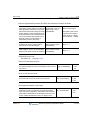
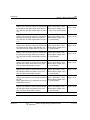
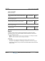
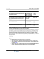
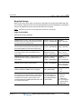
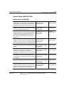
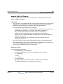
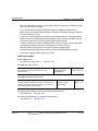
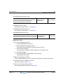
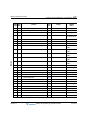
REVISION HISTORY
Release
3.5
Date
Documentation Changes
06-10 Call Screening - MB owner can listen to msg while being left in mailbox.
The following VM related features and enhancements were added:
Administrator Mailbox - allows user to perform Admin MB functions.
3.0
2.1
-C-1
C-4
E-mail Notification of VM Msgs - sends e-mail when VM msg is rec’d.
C-11
Message Cascading - allows duplicate msgs in multiple mailboxes.
C-18
Outcall Notification - set parameters to notify when call is received.
C-22
Virtual Mailboxes - allows stations to function w/o physical hardware.
C-25
Voice Mailbox COS - set different MB parameters by class of service.
C-30
11-09 A CO Line Preset Forward feature was added to allow a call to ring at
multiple stations (PGM 141, Flex 13-15).
1-43
Station Call Coverage now supports Hunt Group pilot numbers.
1-80
Flex button 4 has been added to the CCR table in PGM 228 to play a
designated VM announcement to callers when the destination is busy.
1-123
New CCR destination type has been added to PGM 228 to prompt an
Attendant to record a system greeting (locally or remote).
1-124
Use of Vertical DECT digital cordless phones is supported.
1-149
Setup and Line parameters have been added to support the T1 board.
1-226
12-08 This reformatted SBX IP Programming & Operations Guide
consolidates features, programming, and operations into 1 book.
->
Release 3.5
1-38
Announce Only Mailbox - specify caller action, no msgs taken.
-> Sections include: 1) Basic Features, A) Networking,
B) VoIP, C) Voicemail, D) Quick Ref, and E) Quick Start.
2.0
Page No.
See
Table of
Contents
No 2.0 system features have been added or removed.
07-08 A "Quick Start Topics" appendix has been added.
E-1
Use of Vertical Ranger digital cordless phones is supported
1-149
A Company Directory feature has been added to PGM 110: FLEX 3 & 4
for first/last names. A 6* station programming code is added to record
the VMIB Subscriber Name.
1-44
Also, a new CCR dial digit (12) was added, which represents a
Company Directory request.
1-124
June 2010
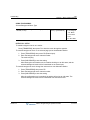
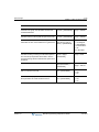
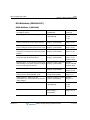
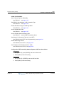
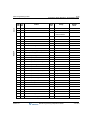
REVISION HISTORY
Release
Date
Documentation Changes
2.0 (cont) 07-08 A new CCR dial digit has been added to PGM 228 to indicate a Mailbox
Owner button.
Page No.
1-124 &
Also, 3 new destinations have been added: Busy, No Answer, and Time
Out/Error.
1-123
PGM 141 - FLEX 11 has been added to enable/disable the marking of a
CO line(s) for 911 use.
1-5
Daylight Saving Time feature has been added (PGM 178 -FLEX 3-5).
1-234
DND Forward feature has been added (PGM 113 - FLEX 19).
1-50
911 feature is added.
1-5
The Weekly Time Table (PGM 233) has been modified to add Lunch
Start and End Times.
1-14
Pre-selected Message DND feature was added (PGM 113 - FLEX 16) .
1-51
DID Call Routing and Incoming CLI feature has been added (PGM 237).
1-129
DID/DISA DND/Pre-selected Message Destination feature has been
added to PGM 167.
- This feature replaces PGM 167 -FLEX 4 features of Busy Prompt
Usage, Error Prompt Usage, DND Prompt Usage, No Answer Prompt
Usage, and Attendant Transfer Prompt Usage and moves them to
PGM 167 - FLEX 5.
1-122
- This move displaces Reroute Busy Destination, Reroute Error
Destination, and Reroute No Answer Destination from FLEX 5-7 to
FLEX 6-8.
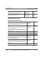
PGM 143 - FLEX 14-18 have been added:
- Screening
1.0
1-223
- Double CLI Service/Calling Party Number Service
1-145
- Deny Incoming Call
1-224
- ICLID Usage
1-130
Transit-Out Security feature is added.
A-19
PGM 324 - FLEX 9-11 have been added: Net Firewall Routing,
Authorization Code COS Use, and SMDR Dial Hidden.
A-25
01-08 Initial Release
--
NOTES --1) Manual contains information on ISDN, DCOB,
and SMS features that are not currently supported.
2) Information about DID pertains only to SIP Trunking.
Release 3.5
June 2010
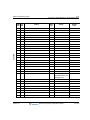
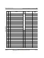
Contents
Chapter 1
Basic System Features
General Information - - - - - - - - - - - - - - - - - - - - - - - - - - - - - - - 1-1
Reference Material - - - - - - - - - - - - - - - - - - - - - - - - - - - - - 1-1
About This Guide - - - - - - - - - - - - - - - - - - - - - - - - - - - - - - 1-2
Programming Guidelines - - - - - - - - - - - - - - - - - - - - - - - - - 1-2
911 Feature - - - - - - - - - - - - - - - - - - - - - - - - - - - - - - - - - - - - - 1-5
Attendant Service - - - - - - - - - - - - - - - - - - - - - - - - - - - - - - - - - 1-6
Assigning an Attendant - - - - - - - - - - - - - - - - - - - - - - - - - - 1-6
Attendant Call & Queuing - - - - - - - - - - - - - - - - - - - - - - - - 1-7
Attendant Forward - - - - - - - - - - - - - - - - - - - - - - - - - - - - - 1-8
Attendant Intrusion - - - - - - - - - - - - - - - - - - - - - - - - - - - - - 1-8
Attendant Override - - - - - - - - - - - - - - - - - - - - - - - - - - - - - 1-9
Attendant Recall - - - - - - - - - - - - - - - - - - - - - - - - - - - - - - 1-10
LCD Date/Time Display - - - - - - - - - - - - - - - - - - - - - - - - - 1-11
Day/Night Service - - - - - - - - - - - - - - - - - - - - - - - - - - - - - 1-12
Outgoing Access - - - - - - - - - - - - - - - - - - - - - - - - - - - - - - 1-15
DSS/BLF Consoles - - - - - - - - - - - - - - - - - - - - - - - - - - - - 1-16
ICM Box Music - - - - - - - - - - - - - - - - - - - - - - - - - - - - - - - 1-17
Station Feature Cancel - - - - - - - - - - - - - - - - - - - - - - - - - 1-18
Call Control - - - - - - - - - - - - - - - - - - - - - - - - - - - - - - - - - - - - 1-18
Account Code - - - - - - - - - - - - - - - - - - - - - - - - - - - - - - - - 1-18
Authorization Code - - - - - - - - - - - - - - - - - - - - - - - - - - - - 1-20
Automatic Call Release - - - - - - - - - - - - - - - - - - - - - - - - - 1-22
Class Of Service (COS) - - - - - - - - - - - - - - - - - - - - - - - - - 1-23
System Speed Zone - - - - - - - - - - - - - - - - - - - - - - - - - - - 1-29
Walking Class of Service (Walking COS) - - - - - - - - - - - - 1-30
Call Handling - - - - - - - - - - - - - - - - - - - - - - - - - - - - - - - - - - - 1-31
Alarm - - - - - - - - - - - - - - - - - - - - - - - - - - - - - - - - - - - - - - 1-31
Release 3.5
SBX IP Programming & Operations Guide
June 2010
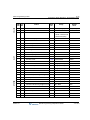
Contents
TOC-2
Automatic Incoming Fax Transfer - - - - - - - - - - - - - - - - - Automatic Privacy - - - - - - - - - - - - - - - - - - - - - - - - - - - - Barge In - - - - - - - - - - - - - - - - - - - - - - - - - - - - - - - - - - - Background Music (BGM) - - - - - - - - - - - - - - - - - - - - - - - Call Log (Models 7208D/7224D only) - - - - - - - - - - - - - - - Call Screening - - - - - - - - - - - - - - - - - - - - - - - - - - - - - - - Camp-on - - - - - - - - - - - - - - - - - - - - - - - - - - - - - - - - - - - Chime Bell - - - - - - - - - - - - - - - - - - - - - - - - - - - - - - - - - - CLI Display - SLT Feature - - - - - - - - - - - - - - - - - - - - - - - CO Line Preset Forward - - - - - - - - - - - - - - - - - - - - - - - - Company Directory - - - - - - - - - - - - - - - - - - - - - - - - - - - - Data Line Security - - - - - - - - - - - - - - - - - - - - - - - - - - - - Dialing Security - - - - - - - - - - - - - - - - - - - - - - - - - - - - - - Distinctive Ring Tone - - - - - - - - - - - - - - - - - - - - - - - - - - Do Not Disturb (DND) - - - - - - - - - - - - - - - - - - - - - - - - - - Do Not Disturb (DND) Forward to Voice Mail - - - - - - - - - Do Not Disturb (One Time DND) - - - - - - - - - - - - - - - - - - Do Not Disturb (DND) with Pre-Selected Message - - - - - Emergency Intrusion - - - - - - - - - - - - - - - - - - - - - - - - - - - Extend CO-to-CO Connection - - - - - - - - - - - - - - - - - - - - Flash - - - - - - - - - - - - - - - - - - - - - - - - - - - - - - - - - - - - - - Flex Buttons - - - - - - - - - - - - - - - - - - - - - - - - - - - - - - - - Forced Hands-Free Mode - - - - - - - - - - - - - - - - - - - - - - - Forced Trunk Disconnect - - - - - - - - - - - - - - - - - - - - - - - Headset - - - - - - - - - - - - - - - - - - - - - - - - - - - - - - - - - - - Hot Desk - - - - - - - - - - - - - - - - - - - - - - - - - - - - - - - - - - - In-Room Indication - - - - - - - - - - - - - - - - - - - - - - - - - - - - Intercom Signal Mode (HF/TN/PV) - - - - - - - - - - - - - - - - - Intercom Tenancy Group - - - - - - - - - - - - - - - - - - - - - - - Message Wait and Call Back - - - - - - - - - - - - - - - - - - - - - Message Wait Indicator LEDs - - - - - - - - - - - - - - - - - - - - Message Wait Indication (MWI) - SLT Feature - - - - - - - - Messages (Customized Display Text) - - - - - - - - - - - - - - -
Release 3.5
SBX IP Programming & Operations Guide
1-32
1-33
1-34
1-35
1-37
1-38
1-39
1-41
1-42
1-43
1-44
1-47
1-48
1-48
1-49
1-50
1-50
1-51
1-52
1-53
1-54
1-55
1-58
1-59
1-60
1-61
1-63
1-64
1-65
1-66
1-67
1-70
1-70
June 2010
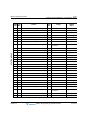
Contents
TOC-3
Mobile Extension - - - - - - - - - - - - - - - - - - - - - - - - - - - - - 1-73
Music On Hold (MOH) - - - - - - - - - - - - - - - - - - - - - - - - - - 1-76
Mute - - - - - - - - - - - - - - - - - - - - - - - - - - - - - - - - - - - - - - 1-77
On-Hook Dialing - - - - - - - - - - - - - - - - - - - - - - - - - - - - - - 1-78
Remote Mobile Extension Control - - - - - - - - - - - - - - - - - - 1-79
Station Call Coverage - - - - - - - - - - - - - - - - - - - - - - - - - - 1-80
Station Name Programming (Dial-by-Name) - - - - - - - - - - 1-81
Station Port Blocking - - - - - - - - - - - - - - - - - - - - - - - - - - - 1-83
Station User Programming - - - - - - - - - - - - - - - - - - - - - - - 1-83
Station Relocation - - - - - - - - - - - - - - - - - - - - - - - - - - - - - 1-84
Station Serial Call (Internal Calls Only) - - - - - - - - - - - - - - 1-85
Time & Date Setup (Digital network Only) - - - - - - - - - - - - 1-85
Voice Over - - - - - - - - - - - - - - - - - - - - - - - - - - - - - - - - - - 1-85
Wakeup - - - - - - - - - - - - - - - - - - - - - - - - - - - - - - - - - - - - 1-87
Conference Calls - - - - - - - - - - - - - - - - - - - - - - - - - - - - - - - - 1-89
Multi-line Conferences - - - - - - - - - - - - - - - - - - - - - - - - - - 1-89
Conference Room - - - - - - - - - - - - - - - - - - - - - - - - - - - - - 1-90
Paging Conference - - - - - - - - - - - - - - - - - - - - - - - - - - - - 1-93
SLT Conference - - - - - - - - - - - - - - - - - - - - - - - - - - - - - - 1-94
External Device Control - - - - - - - - - - - - - - - - - - - - - - - - - - - 1-94
Door Open - - - - - - - - - - - - - - - - - - - - - - - - - - - - - - - - - - 1-94
Doorboxes - - - - - - - - - - - - - - - - - - - - - - - - - - - - - - - - - - 1-95
Loud Bell - - - - - - - - - - - - - - - - - - - - - - - - - - - - - - - - - - - 1-97
Hunt Groups - - - - - - - - - - - - - - - - - - - - - - - - - - - - - - - - - - - 1-98
Circular/Terminal Hunt Groups - - - - - - - - - - - - - - - - - - - 1-101
Unified Call Distribution Groups (UCD Groups) - - - - - - - 1-103
Ring Hunt Groups - - - - - - - - - - - - - - - - - - - - - - - - - - - - 1-114
Voice Mail Hunt Groups (SLT only) - - - - - - - - - - - - - - - - 1-116
Pick-Up Groups - - - - - - - - - - - - - - - - - - - - - - - - - - - - - 1-117
Hunt Group Name Service - - - - - - - - - - - - - - - - - - - - - - 1-117
Incoming Call Pickup - - - - - - - - - - - - - - - - - - - - - - - - - - - - 1-119
CO Line Name - - - - - - - - - - - - - - - - - - - - - - - - - - - - - - 1-119
Customer Call Routing (CCR) with Voice Mail - - - - - - - - 1-119
Release 3.5
SBX IP Programming & Operations Guide
June 2010
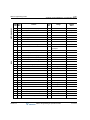
Contents
TOC-4
Direct Inward Dialing (DID) - - - - - - - - - - - - - - - - - - - - - DID Call Routing with Incoming CLI - - - - - - - - - - - - - - - DID/DISA Call Routing for Station in DND or Pre-selected
Message Mode - - - - - - - - - - - - - - - - - - - - - - - - - - - - - Direct Inward System Access (DISA) - - - - - - - - - - - - - - Preferred Line Answer (PLA) - - - - - - - - - - - - - - - - - - - - Ring Assignment - - - - - - - - - - - - - - - - - - - - - - - - - - - - Universal Night Answer (UNA) - - - - - - - - - - - - - - - - - - - IP Phone Reroute Service - - - - - - - - - - - - - - - - - - - - - - - - ISDN Service - - - - - - - - - - - - - - - - - - - - - - - - - - - - - - - - - Calling Line Identification Presentation (CLI) - - - - - - - - - Calling Party Number (CPN) Service - - - - - - - - - - - - - - Linked Stations - - - - - - - - - - - - - - - - - - - - - - - - - - - - - - - - Executive/Secretary Pairs - - - - - - - - - - - - - - - - - - - - - - Linked-Pair Stations - - - - - - - - - - - - - - - - - - - - - - - - - - Outgoing Call Access - - - - - - - - - - - - - - - - - - - - - - - - - - - - Basic Access - - - - - - - - - - - - - - - - - - - - - - - - - - - - - - - Call Time Restriction - - - - - - - - - - - - - - - - - - - - - - - - - CO Line Queuing - - - - - - - - - - - - - - - - - - - - - - - - - - - - CO Step Call - SLT Phones Only - - - - - - - - - - - - - - - - - Emergency Call Service - - - - - - - - - - - - - - - - - - - - - - - Hot Line & Warm Line - - - - - - - - - - - - - - - - - - - - - - - - - Least Cost Routing (LCR) - - - - - - - - - - - - - - - - - - - - - - Memory Dialing - - - - - - - - - - - - - - - - - - - - - - - - - - - - - Private Line (Digital Phones only) - - - - - - - - - - - - - - - - Paging - - - - - - - - - - - - - - - - - - - - - - - - - - - - - - - - - - - - - - Internal, External, All-Call, and Meet-Me Page - - - - - - - Pre-recorded (VMIB) Message - - - - - - - - - - - - - - - - - - SOS Paging (Digital Phones only) - - - - - - - - - - - - - - - - Push-to-Talk (PTT) - (Nomad IP Phones only) - - - - - - - Rerouting - - - - - - - - - - - - - - - - - - - - - - - - - - - - - - - - - - - - Call Forward - - - - - - - - - - - - - - - - - - - - - - - - - - - - - - - Call Transfer - - - - - - - - - - - - - - - - - - - - - - - - - - - - - - - -
Release 3.5
SBX IP Programming & Operations Guide
1-125
1-128
1-130
1-131
1-134
1-135
1-136
1-137
1-137
1-138
1-145
1-146
1-146
1-148
1-149
1-149
1-152
1-153
1-154
1-154
1-154
1-156
1-164
1-173
1-173
1-173
1-176
1-177
1-178
1-178
1-178
1-184
June 2010
Contents
TOC-5
Holding and Parking - - - - - - - - - - - - - - - - - - - - - - - - - - 1-187
Pick-Up - - - - - - - - - - - - - - - - - - - - - - - - - - - - - - - - - - - 1-191
Software Upgrade - - - - - - - - - - - - - - - - - - - - - - - - - - - - - - 1-194
LAN Connection - - - - - - - - - - - - - - - - - - - - - - - - - - - - - 1-194
Modem Connection - - - - - - - - - - - - - - - - - - - - - - - - - - - 1-196
Serial (COM port) - - - - - - - - - - - - - - - - - - - - - - - - - - - - 1-198
Station Message Detail Recording (SMDR) - - - - - - - - - - - - 1-200
Print-out - Lost Call - - - - - - - - - - - - - - - - - - - - - - - - - - - 1-203
Supplementary Service - - - - - - - - - - - - - - - - - - - - - - - - - - - 1-206
Message Wait Notification to Mobile Extension (SIP Trunks only)
1-206
Traffic Analysis - - - - - - - - - - - - - - - - - - - - - - - - - - - - - - - - 1-206
Attendant Reports - - - - - - - - - - - - - - - - - - - - - - - - - - - - 1-208
Call Reports - - - - - - - - - - - - - - - - - - - - - - - - - - - - - - - - 1-209
CO Reports - - - - - - - - - - - - - - - - - - - - - - - - - - - - - - - - 1-211
Hardware (H/W) Unit Reports - - - - - - - - - - - - - - - - - - - - 1-212
Other Programming Tables - - - - - - - - - - - - - - - - - - - - - - - - 1-214
Station Attributes 1 (PGM 111) - - - - - - - - - - - - - - - - - - - 1-214
Station Attributes 2 (PGM 112) - - - - - - - - - - - - - - - - - - - 1-215
Station Attributes 3 (PGM 113) - - - - - - - - - - - - - - - - - - - 1-216
Station Attributes 4 (PGM 114) - - - - - - - - - - - - - - - - - - - 1-217
SMDR Account Group (PGM 124) - - - - - - - - - - - - - - - - 1-218
Copy DSS Button (PGM 125) - - - - - - - - - - - - - - - - - - - - 1-219
Station IP List (PGM 126) - - - - - - - - - - - - - - - - - - - - - - 1-219
Display Station Number By COS / By CO Group (PGM 130-131)
1-220
CO Line (PGM 140-146) - - - - - - - - - - - - - - - - - - - - - - - 1-220
Slot Base Program (PGM 155) - - - - - - - - - - - - - - - - - - - 1-225
System Data (PGM 160-184) - - - - - - - - - - - - - - - - - - - - 1-226
System Timers (PGM 180-184) - - - - - - - - - - - - - - - - - - 1-235
DCOB Attribute (PGM 186-187) - - - - - - - - - - - - - - - - - - 1-238
ISDN System Base Program - - - - - - - - - - - - - - - - - - - - 1-240
Tables - - - - - - - - - - - - - - - - - - - - - - - - - - - - - - - - - - - - 1-241
Nation Specific (PGM 401-424) - - - - - - - - - - - - - - - - - - 1-242
Release 3.5
SBX IP Programming & Operations Guide
June 2010
Contents
TOC-6
Initialization (PGM 450) - - - - - - - - - - - - - - - - - - - - - - - - - 1-247
Print Prot Database (PGM 451) - - - - - - - - - - - - - - - - - - - 1-248
Appendix A
Networking Services
Internet Protocol (H.450) - - - - - - - - - - - - - - - - - - - - - - - - - - - A-1
Networking Basics - - - - - - - - - - - - - - - - - - - - - - - - - - - - - A-1
Display Messages (Absent Text Message) - - - - - - - - - - - - A-2
Attendant Call Service (CAS) - - - - - - - - - - - - - - - - - - - - - A-2
Busy Lamp Field (BLF) - - - - - - - - - - - - - - - - - - - - - - - - - - A-3
Call Completion - - - - - - - - - - - - - - - - - - - - - - - - - - - - - - - A-4
Call Offer - - - - - - - - - - - - - - - - - - - - - - - - - - - - - - - - - - - - A-5
Centralized SMDR for Network (Transit) Calls - - - - - - - - - - A-6
Centralized Voice Mail System (VMS) - - - - - - - - - - - - - - - A-7
CO Ring Assignment - - - - - - - - - - - - - - - - - - - - - - - - - - - A-7
CO Transit - In - - - - - - - - - - - - - - - - - - - - - - - - - - - - - - - - A-8
CO Transit - Out - - - - - - - - - - - - - - - - - - - - - - - - - - - - - - - A-9
Do-Not-Disturb (DND) with Network Calls - - - - - - - - - - - - A-10
Identification Service - - - - - - - - - - - - - - - - - - - - - - - - - - A-11
Network Message Waiting Indicator (MWI) - - - - - - - - - - - A-11
Network Call (Net Call) - - - - - - - - - - - - - - - - - - - - - - - - - A-13
Network (Net) Call Forward - - - - - - - - - - - - - - - - - - - - - - A-14
Network Follow-Me Forward - - - - - - - - - - - - - - - - - - - - - A-15
Network Conference - - - - - - - - - - - - - - - - - - - - - - - - - - - A-16
Network Firewall Routing - - - - - - - - - - - - - - - - - - - - - - - A-17
Network (Net) Transfer - - - - - - - - - - - - - - - - - - - - - - - - - A-17
Security of Transit-Out Code with registered IP - - - - - - - - A-18
VOIP Networking - - - - - - - - - - - - - - - - - - - - - - - - - - - - - A-19
Networking Programming Tables - - - - - - - - - - - - - - - - - - - - A-22
Networking Basic Attributes (PGM 320) - - - - - - - - - - - - - A-22
Networking Supplementary Attributes (PGM 321) - - - - - - A-23
Networking CO Line Attributes (PGM 322) - - - - - - - - - - - A-24
Networking Routing Table (PGM 324) - - - - - - - - - - - - - - A-24
Release 3.5
SBX IP Programming & Operations Guide
June 2010
Contents
Appendix B
TOC-7
VoIP Service
Call By IP Address - - - - - - - - - - - - - - - - - - - - - - - - - - - - - - - - B-1
Call by Routing Table - - - - - - - - - - - - - - - - - - - - - - - - - - - - - - B-3
Early H.245 - - - - - - - - - - - - - - - - - - - - - - - - - - - - - - - - - - - - - B-4
H.245 Tunneling - - - - - - - - - - - - - - - - - - - - - - - - - - - - - - - - - - B-5
Normal/Fast mode for H.323 - - - - - - - - - - - - - - - - - - - - - - - - - B-5
TOS for H.323 - - - - - - - - - - - - - - - - - - - - - - - - - - - - - - - - - - - B-6
Other VOIB Programming Codes - - - - - - - - - - - - - - - - - - - - - - B-8
VOIP IP Setting (340) - - - - - - - - - - - - - - - - - - - - - - - - - - - B-8
Gatekeeper Setting (PGM 341) - - - - - - - - - - - - - - - - - - - B-10
RSG/IP Phone Programming (PGM 380-397) - - - - - - - - - B-11
SIP Programming (PGM 500-501) - - - - - - - - - - - - - - - - - - - - B-15
SIP Attributes I (PGM 500) - - - - - - - - - - - - - - - - - - - - - - - B-15
SIP Attributes II (PGM 501) - - - - - - - - - - - - - - - - - - - - - - B-16
Appendix C
Voicemail Service
Administrator Mailbox - - - - - - - - - - - - - - - - - - - - - - - - - - - - - - C-1
Using Admin Mailbox Options - - - - - - - - - - - - - - - - - - - - - C-1
Announce Only Mailbox - - - - - - - - - - - - - - - - - - - - - - - - - - - - C-4
Announcements - - - - - - - - - - - - - - - - - - - - - - - - - - - - - - - - - - C-5
Record System Greetings - - - - - - - - - - - - - - - - - - - - - - - - C-5
Record User VM Greetings - - - - - - - - - - - - - - - - - - - - - - - C-7
Calls to Voicemail - - - - - - - - - - - - - - - - - - - - - - - - - - - - - - - - C-10
DID Call to a Station Voice Mailbox - - - - - - - - - - - - - - - - C-10
Direct Transfer to VMIB - - - - - - - - - - - - - - - - - - - - - - - - - C-11
E-Mail Notification of VM Messages - - - - - - - - - - - - - - - - C-11
No Answer Call (Forward) to VMIB - - - - - - - - - - - - - - - - - C-13
Remote Control - - - - - - - - - - - - - - - - - - - - - - - - - - - - - - C-14
Return Call Using CLI (8224D phones only) - - - - - - - - - - C-16
Mailbox Buttons - - - - - - - - - - - - - - - - - - - - - - - - - - - - - - - - - C-16
Setting Up a Mailbox Button - - - - - - - - - - - - - - - - - - - - - - C-16
Messages - - - - - - - - - - - - - - - - - - - - - - - - - - - - - - - - - - - - - C-18
Release 3.5
SBX IP Programming & Operations Guide
June 2010
Contents
TOC-8
Copy Messages to Another Mailbox (Cascading) - - - - - Forward Messages to Another Mailbox - - - - - - - - - - - - - Forward Messages to AA & Rerouting to Another Station Reply to Messages - - - - - - - - - - - - - - - - - - - - - - - - - - - Transfer Messages - - - - - - - - - - - - - - - - - - - - - - - - - - - Outcall Notification - - - - - - - - - - - - - - - - - - - - - - - - - - - - - - Two-way Record - - - - - - - - - - - - - - - - - - - - - - - - - - - - - - - Recording via SMDI - - - - - - - - - - - - - - - - - - - - - - - - - - Recording via VMIB - - - - - - - - - - - - - - - - - - - - - - - - - - Virtual Mailboxes - - - - - - - - - - - - - - - - - - - - - - - - - - - - - - - Voice Mailbox COS - - - - - - - - - - - - - - - - - - - - - - - - - - - - - Voice Mail Dialing Table - - - - - - - - - - - - - - - - - - - - - - - - - - -
C-18
C-19
C-20
C-20
C-21
C-22
C-23
C-23
C-25
C-25
C-30
C-31
Appendix D Quick Reference - Programming Tables
Admin Programming Codes - - - - - - - - - - - - - - - - - - - - - - - - - D-2
Pre-Programmed System Values - - - - - - - - - - - - - - - - - - - D-2
Feature Default Values - - - - - - - - - - - - - - - - - - - - - - - - - - D-6
Attendant Programming Codes - - - - - - - - - - - - - - - - - - - - - - D-44
Fixed Station Programming Codes - - - - - - - - - - - - - - - - - - - D-45
Flexible Button Programming Codes - - - - - - - - - - - - - - - - - - D-46
Flexible Numbering Plan - - - - - - - - - - - - - - - - - - - - - - - - - - D-47
Station User Programming Codes - - - - - - - - - - - - - - - - - - - - D-48
Character Entry Chart - - - - - - - - - - - - - - - - - - - - - - - - - - - - D-50
Appendix E
Quick Start Topics
Setting Up Voice Mail - - - - - - - - - - - - - - - - - - - - - - - - - - - - - Record a Voice Mail Greeting For Station 101 - - - - - - - - - Using The Phone to Set Password And Forward Settings Overriding the Forward Set by ADMIN PROGRAMMING - Using the Online Admin Tool to Make Password & Forward
Settings - - - - - - - - - - - - - - - - - - - - - - - - - - - - - - - - - - - - Program Station Forwarding - - - - - - - - - - - - - - - - - - - - - -
Release 3.5
SBX IP Programming & Operations Guide
E-1
E-1
E-2
E-3
E-4
E-5
June 2010
Contents
TOC-9
General Information about Voice Mail - - - - - - - - - - - - - - - - E-6
Turn On Voice Mail Notification to a Cell Phone - - - - - - - - - - - E-7
Using the Phone to Associate CO Ringing to a Hunt Group - - - E-7
Creating A Ring Group - - - - - - - - - - - - - - - - - - - - - - - - - - E-7
Set the Ring Group Attributes - - - - - - - - - - - - - - - - - - - - - - E-8
Program CO 01-02 To Ring The Hunt Group Days - - - - - - - E-8
Change the Forwarding on Hunt Group 620 to VMB 107 - - E-8
Using PCAdmin to Associate CO Ringing to a Hunt Group - E-9
CO Ringing Hunt Group Overflow Example - - - - - - - - - - - E-14
Auto Attendant Customer Call Routing Setup (Example) - - - - E-18
Programming Via Phone - - - - - - - - - - - - - - - - - - - - - - - - E-18
Programming Via PCAdmin - - - - - - - - - - - - - - - - - - - - - - E-19
Instructions for Recording Greetings and Prompts - - - - - - E-20
Networking Two SBX IP Systems - - - - - - - - - - - - - - - - - - - - E-21
System A Programming - - - - - - - - - - - - - - - - - - - - - - - - - E-22
System B Programming - - - - - - - - - - - - - - - - - - - - - - - - - E-33
To Draw Dial tone Across the Net - - - - - - - - - - - - - - - - - - E-45
Remote IP Phone Setup - - - - - - - - - - - - - - - - - - - - - - - - - - - E-50
IP Addressing - - - - - - - - - - - - - - - - - - - - - - - - - - - - - - - - E-50
Configuring IP Phone Settings - - - - - - - - - - - - - - - - - - - - E-57
Programming VOIP card settings from a digital keyset - - - E-59
Index
Release 3.5
SBX IP Programming & Operations Guide
June 2010
THIS P A GE INTENTIONALLY LEF T B LANK
Release 3.5
June 2010
Chapter 1
Basic System Features
General Information
Reference Material
A variety of documents support the SBX IP system. All SBX documents are on a single CD that
ships with each system. These files are available in PDF format and can also be downloaded
from the Vertical website at: http://Vconnect.vertical.com.
System Documentation
Release 1.0 and 2.0
SBX IP Installation Guide - detailed information for hardware installation
SBX IP Features & Operation Guide - description & operating instructions for features
SBX IP Programming Guide - system programming information
Release 3.0 or higher
SBX IP Installation Guide
SBX IP Prog & Opns Guide - replaces Feature/Description Guide & Programming Guide
End User Documents
SBX IP Phone User Guide
SBX 8-button Phone QRC
SBX 24-button Phone QRC
SBX Voice Mail In-skin QRC
Associated Windows-based Applications
PC Admin - the primary tool for programming and administering SBX IP systems
PC Admin Offline Editor - offline version database editing tool
Speed Editor - a tool for managing system speed dials
ez Phone - a CTI application for SBX phone users
Nomad SP Soft Phone - PC-version of the IP remote phone
Release 3.5
SBX IP Programming & Operations Guide
June 2010
General Information
1-2
Chapter 1: Basic System Features
About This Guide
This manual is designed to provide information regarding SBX IP 320 general system feature
operation. In most cases, each feature described will contain three sections in the following
order:
•
CONDITIONS: explains any requirements or constraints of the feature related to its
configuration.
•
ADMIN PROGRAMMING: provides information about configuring the feature using a
digital phone.
•
OPERATION / SETUP: describes how to use and/or set up the feature using a digital
phone.
Programming Guidelines
The SBX IP System can be programmed to meet each customer's individual needs. The
elements of Basic Admin Pre-programming are covered in the SBX IP Installation Guide, and
can help to ensure you are prepared for Admin Programming of your SBX IP System.
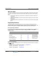
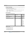
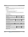
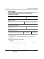
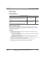
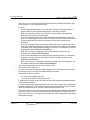
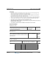
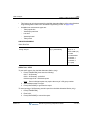
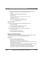
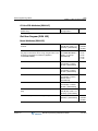
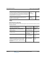
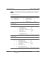
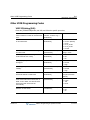
Pre-Programming (Installation)
Pre-programming for the following should have been done immediately following Installation of
the SBX IP System. For details, refer to Chapter 6 "Starting the SBX IP" in the SBX IP
Installation Guide.
Feature
PGM Code
Install Guide (page #)
Default System (Reset)
450
6-5
Site Name
100
6-6
Board Assignment
101
6-8
Numbering Plan Type
104
6-10
System IP Settings
108
6-14
If you have the 3.0
Install Guide "open",
you can use the blue
hyperlinks to "jump"
to these locations ...
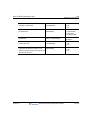
PC Admin Programming
You must use the PC Admin application to set the following IP parameters which are located in
the VoIP appendix:
PGM 386 - IP Phone Attributes (MAC address) … see page B-13
PGM 500 - SIP Attributes I … see page B-15
PGM 501 - SIP Attributes II … see page B-16
Release 3.5
SBX IP Programming & Operations Guide
June 2010
General Information
1-3
Chapter 1: Basic System Features
Programming Using the Keyset
All programming is done at one station (Station 100, Station Port #00, by default) using the
4024-00 Digital Key Telephone (DKT).
Additional programming stations may be assigned, but only one DKT can be active in the
programming mode at any one time.
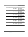
Admin (DKTU only) -- if value is set to
ON, the assigned station users can
program the Admin Database.
PGM 113 + FLEX 1 + 0
(Disable) + [HOLD/SAVE]
VALUES -0 = Disable (default)
1 = Enable
(Default = Enable for Admin
Station at station port 1 only)
Programming Mode -- when in programming mode, Station 100 does not operate as a
normal telephone, but instead works as a programming instrument with all of the buttons
redefined. The keys of the dial pad are used to enter the various data fields to enter
numerical information.
Flexible Buttons -- the 24 buttons located on the right side of the phone are used to
indicate a specific data field and to enter information.
Soft Buttons -- the 3 functional soft buttons are used to go BACK to a previous menu, to
DELETE data, or to SAVE data input.
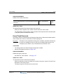
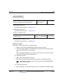
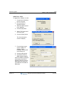
Entering Programming Mode
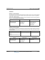
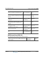
To assign an Admin Password:
Admin Password -- an Admin password can be
assigned for entering Admin Programming
mode, as a security measure. To delete the
Admin password, press the [SPEED] button.
PGM 162 + Password (4
digits - *, #, 0-9) +
[HOLD/SAVE]
VALUES -Default = not assigned
# = ignore received digit
* = bypass the digit
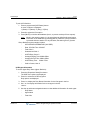
To enter programming mode:
1. Lift the Handset or press the speaker button on the Admin station.
2. Press the [TRANS/PGM] button and dial * #.
A confirmation tone will sound.
3. Enter the Admin password, if a password has been set; a confirmation tone sounds
indicating that the Station is in Admin Programming mode.
Release 3.5
SBX IP Programming & Operations Guide
June 2010
General Information
1-4
Chapter 1: Basic System Features
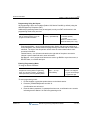
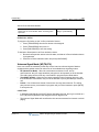
By default, there is no password.
AD MIN P ROGRAM START
BACK
DE LET E
SAVE
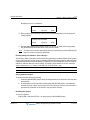
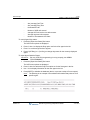
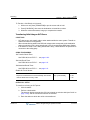
4. Each program is accessed by pressing the [TRANS/PGM] button The following will
initially display:
ENTER PGM NUMBER
BACK
DE LET E
SAVE
5. Dial the desired three-digit program number. If an error is made while entering data,
the [TRANS/PGM] button will return to the previous status.
NOTE:
To return to the previous state while in Admin Programming, press the [BACK] soft
button to clear the temporary data fields.
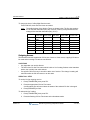
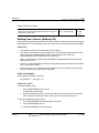
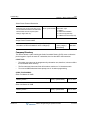
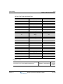
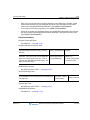
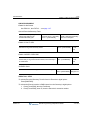
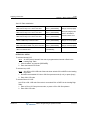
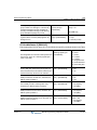
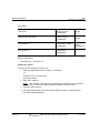
Entering Ranges for Stations, COs, & Groups
The following Table is frequently used in Admin Programming procedures. When entering each
range, refer to the table, as the range is not always mentioned in the procedures. When entering
a programming area that involves stations or CO lines, you are prompted to enter the range of
stations or CO lines that you want to modify. To modify a single station or CO line, enter the
same number twice, e.g., 100100 = Sta 100 only, 01-01 CO line 1 only.
STATION RANGE
CO RANGE
CO LINE GROUP RANGE
100-131
01-12
01-24
Saving System Changes
To accept changes while programming:
1. Press the [HOLD/SAVE] button when all changes have been entered to store the data
permanently.
2. A confirmation tone sounds when pressing the [HOLD/SAVE] button, if all data was
entered correctly. If there were any errors in the entering of data, an error tone will be
presented and data will not be stored in the permanent memory.
Resetting the System
To reset the System:
Enter [PGM] + 450 then [FLEX] + 15 and press the [HOLD/SAVE] button.
Release 3.5
SBX IP Programming & Operations Guide
June 2010
911 Feature
1-5
Chapter 1: Basic System Features
911 Feature
The 911 feature was designed to give users one-button access to this emergency number. Any
phone can be programmed with a Flex button designated specifically for 911 calls. When using
this button, and all lines are busy, an active call is dropped so the 911 call can be placed.
IMPORTANT:
A 911 button can be configured so that an access code (such as 9) is not required
before the 911 is dialed.
Also, any station user who programs a flex button for 911 ALERT will be notified whenever an
internal station places a 911 call. The system can store the last sixteen 911 calls placed, as well
as associated call information (e.g., time/date of call, and station no. where call was placed).
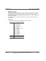
The initial 911 Alert indications include:
•
Audible ringing tone
•
Green flashing 911 ALERT flex button LED
•
Automatic LCD display of 911 call information
CONDITIONS
•
Based on the trunk access code assigned by the System Administrator, a station user can
place an emergency call in one of two ways:
•
-
if the trunk access code is 9 by default, a station must dial 9 + 911.
-
if the trunk access code is other than 9, a station can dial 911.
If all trunks are busy, the system will drop an in-progress trunk, wait 1.5 seconds, and then
dial the 911 call.
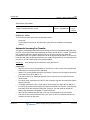
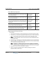
ADMIN PROGRAMMING
E911 Usage -- if value is set to ON, the
PGM 141 + FLEX 11 +
designated CO Line is active for E911 use. (Value)
VALUES -0 = Off
1 = On
Default: CO Line 01 is set to ON;
all other CO Lines are set to OFF.
OPERATION / SETUP
To place an emergency call:
Dial 9 + 911, or, 911 (see CONDITIONS).
To assign a 911 feature button for Alert:
1. Press [TRANS/PGM], then press the Flex button to be assigned.
2. Press [TRANS/PGM], then enter 7#; press [HOLD/SAVE] to store the setting.
Release 3.5
SBX IP Programming & Operations Guide
June 2010
Attendant Service
1-6
Chapter 1: Basic System Features
Attendant Service
An Attendant can be configured to control the incoming calls by answering and transferring
calls, etc. There are two types of Attendants available for configuration within the system. One
Attendant can change simple settings of the whole system; the other provides programming for
intercom tenancy groups (LCD date/time format, etc.):
Main Attendant -- a maximum of five stations can be defined as Main Attendants. These
Attendants control and effect the whole system. The "first" main Attendant is called the
"System" Attendant.
System Attendant -- the System Attendant differs from the Main Attendant in regard to call
handling and system management priority. The System Attendant has more priority than
the Main Attendant(s); the System Attendant default is: Station 100.
NOTE:
The System Attendant can be changed, but it cannot be removed. To change the
System Attendant, enter PGM 164 + FLEX 1 + Sta No. + [HOLD/SAVE].
Intercom Tenancy Group Attendant -- each intercom tenancy group can have its own
Attendant. The Intercom Tenancy Group Attendant controls stations belonging to a
specific intercom tenancy group. Intercom Tenancy Group Attendants affect only the
intercom tenancy group to which they belong.
NOTE:
Generally, the Attendant of a station is the Intercom Tenancy Group Attendant to
which the station belongs. However, if an Intercom Tenancy Group Attendant of a
station doesn't exist, the Main Attendant will provide the station with Atd services.
Assigning an Attendant
CONDITIONS
•
An IP phone cannot be assigned as an Attendant.
ADMIN PROGRAMMING
Assign a Main Attendant
Main Attendants Assignment -- Main Attendants
generally serve as call handlers. NOTE: To delete a
Main Attendant, press the FLEX button, and select
Attendant to delete; then press [SPEED] button.
PGM 164 + FLEX 2 +
VALUES -Sta No. + [HOLD/SAVE] Default = not assigned
Range = FLEX 2- 5
Assign an Intercom Tenancy Group Attendant
ICM Tenancy Group Attendant Assign -- each Intercom
Tenancy group may have one attendant. Day / Night Mode
for Intercom Tenancy Groups is set by the Intercom
Tenancy Group Attendant.
Release 3.5
PGM 120 + FLEX 1 +
VALUES -ICM Tenancy Group Atd
Sta No.
(Attendant) + [HOLD/SAVE]
SBX IP Programming & Operations Guide
June 2010
Attendant Service
1-7
Chapter 1: Basic System Features
Attendant Call & Queuing
CONDITIONS
•
If an Attendant calls another busy Attendant, the calling Attendant will hear a busy tone,
and can then Camp-On to the called (but busy) Attendant.
•
If an Attendant activates unconditional Call Forward, the calls to that Attendant will follow
the configured call forward process.
•
If a user dials 0 (zero), it will ring the Assigned Attendant station of the intercom tenancy
group to which the station belongs. If there is no station configured as an Assigned
Attendant, the call will ring the Main Attendant station.
•
Call to any Attendant will be queued, if the Attendant is busy. Then, ring-back tone or MOH
will be provided to the calling party (see page 1-74).
ADMIN PROGRAMMING
Assign a Main Attendant
Use PGM 164 … see page 1-6
Set the MOH Type
Use PGM 171 + FLEX 2 … see page 1-74
Assign the Intercom Group Attendant
Use PGM 120 + FLEX 1 … see page 1-6
Set Attendant Call Queuing (Ring Back Tone/Music On Hold) RBT/MOH
Attendant Call Queuing Ring Back Tone -- if value is set to RBT, ring
back tone is provided to the Station when the Station calls a busy
Attendant; otherwise, the hold tone or VMIB-MOH is provided (PGM
171 - FLEX 2).
PGM 160 + FLEX 1
+ 0 (MOH) +
[HOLD/SAVE]
VALUES -0 = MOH
1 = RBT
OPERATION / SETUP
To call an Attendant:
1. Go off-hook.
2. Press 0 (zero).
-orDial the station number of the Attendant.
Release 3.5
SBX IP Programming & Operations Guide
June 2010
Attendant Service
1-8
Chapter 1: Basic System Features
Attendant Forward
The Attendant can forward (Unconditional Call Forward) a call to another station. The
Forwarded-to station will temporarily substitute for the Attendant while the Attendant is in the
forwarded state.
CONDITIONS
•
If the Attendant assigns Unconditional Call Forward to a Single Line Telephone (SLT) or
Wireless Handset Telephone Unit (WHTU), the Forwarded-to station only serves incoming
calls as an Attendant call or Attendant recall.
•
Attendant features cannot be activated when forward is set to an SLT or WHTU.
OPERATION / SETUP
To activate Attendant Forward:
1. Go off-hook.
2. Press [DND/FWD].
3. Press 1 (for Unconditional Call Forward).
4. Dial the station number.
5. Hang up the handset.
To deactivate Attendant Forward:
In an idle state, press [DND/FWD].
-orIn an off-hook state, press [DND/FWD], then #.
Attendant Intrusion
When an Attendant has an urgent message for a station already on a call on a CO line, the
Attendant can break-into the call to deliver the message to the designated station and the
distant party.
IMPORTANT:
An ATD INTRUSION flex button must be programmed before this operation can
be performed. See "Flex Buttons" on page 1-53.
CONDITIONS
•
To use this feature, the Auto Privacy should be set to OFF, and Override Privilege of the
Attendant should be ENABLED - see ADMIN PROGRAMMING.
•
Also see "Emergency Intrusion" on page 1-50 and "Forced Trunk Disconnect" on
page 1-57.
Release 3.5
SBX IP Programming & Operations Guide
June 2010
Attendant Service
1-9
Chapter 1: Basic System Features
ADMIN PROGRAMMING
Set Auto Privacy
PGM 161 + FLEX 5 … see page 1-34.
Set Privacy Warning Tone
PGM 161 + FLEX 6 … see page 1-34.
Set Override Privilege
PGM 113 + FLEX 4 … see page 1-34.
OPERATION / SETUP
To intrude on a CO call:
1. At the busy tone, press the programmed {ATD INTRUSION} button.
2. After the intrusion tone, converse with the station and/or the CO party.
To assign an {ATD INTRUSION} Flex button:
1. Press [TRANS/PGM], then press the Flex button to be assigned
2. Press [TRANS/PGM], then enter 86.
3. Press [HOLD/SAVE] to store the setting.
Attendant Override
A station in Do Not Disturb (DND) mode generally cannot receive incoming calls - see
"Attendant Intrusion" on page 1-8 and "Barge In" on page 1-34.
The Attendant, however, can temporarily invalidate a station’s DND mode in order to call (and
transfer calls) to that station. In addition, the Camp-On feature can be used to override DND.
CONDITIONS
•
The Attendant can only override a station’s DND mode (to transfer a CO call) if the station
has a CO or LOOP button (refer to the SBX IP 320 Programming Manual for more
information about CO and LOOP buttons.
•
If target station has no CO or CO button, CO call will be recalled to Attendant immediately.
Release 3.5
SBX IP Programming & Operations Guide
June 2010
Attendant Service
1-10
Chapter 1: Basic System Features
OPERATION / SETUP
To override a DND state at a station:
When a DND tone is heard, press *, or the last digit of the dialed station number.
-orPress the programmed Camp-On Flex button. (See "Camp-on" on page 1-38.)
The DND warning tone will be changed to the Intercom ring-back tone at the
Attendant Station. The Attendant can then call a station in the DND state.
To assign the {Camp-On} Flex button:
1. Press [TRANS/PGM], then press the Flex button to be assigned.
2. Press [TRANS/PGM], then enter 85; press [HOLD/SAVE] to store the setting.
Attendant Recall
If the recalled CO call (in the transfer or hold state) is unanswered by the destination station,
the CO call will be directed to the Attendant. The Attendant will receive the Recall ring as per
the setting of the Attendant Recall Timer.
CONDITIONS
•
If the Attendant doesn't answer the CO call for a time equal to the Attendant Recall Timer,
the CO call will be disconnected.
•
If an Attendant for an Intercom Tenancy Group is not assigned, the CO call is recalled to
the System Attendant.
•
When a call in Exclusive Hold is recalled to the Attendant, the call is placed on System
Hold. (See "Hold" on page 1-184.)
•
A Private CO line will not be recalled to the Attendant.
ADMIN PROGRAMMING
Set Attendant Recall Timer
Attendant Recall Timer -- if a recalled call arrives at the
Attendant station, and the Attendant does not answer within
the designated time, the system will disconnect the call.
PGM 180 + FLEX 1 +
01 (2 digits) +
[HOLD/SAVE]
VALUES -Range = 00-60
minutes
Set Hold Recall Timer
I-Hold Recall Timer -- when a recalled call is not answered,
it will recall to the Attendant after the designated time
expires.
Release 3.5
PGM 180 + FLEX 5 +
030 (3 digits) +
[HOLD/SAVE]
SBX IP Programming & Operations Guide
VALUES -Range = 000-300
seconds
June 2010
Attendant Service
1-11
Chapter 1: Basic System Features
LCD Date/Time Display
The Attendant can change the LCD Date/Time display format for stations in the system. There
are two date and two time format options:
•
Date Format Options: MM-DD-YY or DD-MM-YY
Example:
•
May 31, 2008 in MM-DD-YY format is 05-31-08, for DD-MM-YY format is 31-05-08.
Time Format Options: 12H or 24H
Example:
8:30 P.M. in 12-hour format is 08:30 PM, in 24-hour format it is 20:30.
ADMIN PROGRAMMING
Set LCD Time/Date/Language Display Mode
LCD Time Display Mode -- two LCD Time formats
are available: ordinary (12-hour), and military
(24-hour) mode.
PGM 169 + FLEX 1 + 1 (12H) +
[HOLD/SAVE]
VALUES -0 = 24-Hour Mode
1 = 12-Hour Mode
LCD Date Display Mode -- two LCD date formats
are available: Day/Month/Year or
Month/Day/Year mode.
PGM 169 + FLEX 2 + 1
(MMDDYY) + [HOLD/SAVE]
VALUES -0 = DDMMYY
1 = MMDDYY
LCD Language Display Mode -- a choice of 16
LCD language formats can be selected.
PGM 169 + FLEX 3 + VALUE
VALUES -(Range 00-15) + [HOLD/SAVE] 00 = English
01 = Italian
02 = Finnish
03 = Dutch
04 = Swedish
05 = Danish
06 = Norwegian
07 = Hebrew
08 = Germany
09 = French
10 = Portuguese
11 = Spanish
12 = Korean
13 = Estonia
14 = Russian
15 = Turkish
OPERATION / SETUP
To toggle between the Date formats:
Press [TRANS/PGM], then 044.
To toggle between the Time formats:
Press [TRANS/PGM], then 045.
Release 3.5
SBX IP Programming & Operations Guide
June 2010
Attendant Service
1-12
Chapter 1: Basic System Features
Day/Night Service
CO call destinations can be changed according to the time of day. This means that if a call
comes in at 8:00am, it might go to a live Operator, while if it comes in at 8:00pm it might go to
the group or person covering evening calls. In addition, calls coming in during non-business
hours, weekend, or holidays, can be sent to the Auto Attendant, etc.
There are six ring modes: Day / Night / Weekend / On-Demand / Automatic Ring / Lunch
NOTE:
According to ATD ring mode setting, Lunch Mode can be applied in DISA service, Ring Assigned
incoming call, DID service (see ADMIN PROGRAMMING).
CONDITIONS
•
The destination of a CO call can be set differently for each ring mode.
•
Only an Attendant can change the ring mode. However, a user can use ADMIN
PROGRAMMING to set the destination of CO call.
•
Any attendant can change the Ring Mode of an Intercom Tenancy Group. However, when
an Attendant of an Intercom Tenancy Group changes the ring mode, only the ring mode of
the Intercom Tenancy Group to which the Attendant belongs is changed. If a Main
Attendant changes the ring mode, the ring mode of the entire system will be changed.
•
The Automatic Ring mode can be set as Day mode, Night mode, Weekend mode
according to the Weekly Time Table (see above).
•
The On-Demand mode is used to supply a different destination of CO call, except Day
mode, Night mode, or Weekend mode. In addition, it is not available for us as the
Automatic Ring mode.
•
When the ring mode is set to Automatic Ring mode by the Main Attendant, the ring mode
of the system will follow the first table entry (entry number: 00) of the Weekly Time Table.
•
If the system ring mode is changed from the Night/Weekend/On-Demand/Auto Ring mode
to Day mode, the Ring mode of all Intercom Tenancy Groups will change to the previous
ring mode.
•
There is no default assigned to the Lunch Mode.
•
In PGM 144, Weekend mode, Lunch mode, or On-Demand mode, if a station is assigned
as the Ring destination, the only available Ring Delay Count is 0.
IMPORTANT:
Release 3.5
There cannot be two modes in Weekly Time Table set for the same time (for
example, Day Start Time and Lunch Start Time are the same). If this occurs, the
modes set cannot work properly.
SBX IP Programming & Operations Guide
June 2010
Attendant Service
1-13
Chapter 1: Basic System Features
ADMIN PROGRAMMING
Set the DISA Attribute
Use PGM 140 … see page 1-128
Set CO Line Ring Assignment
When CO Service Type (PGM 140) is set to Normal, incoming CO calls are routed
according to the destination assignment. The destination can be a station, Hunt Group,
VMIB announcement, Net-Station, or VM station number. The Ring Assignment is applied
separately to the Day/Night/Weekend/Lunch/On-Demand Ring Mode using FLEX 1-5.
Ring Assignment -- used to set the Ring
Assignment to a Station, Hunt Group, VMIB
Announce, Net-Station, or Auto Fwd to VM.
- To assign a call to a station, the delay value
must be entered. If delay value is set, the call
will begin to ring after delay time has expired.
- To receive incoming calls instantly, delay
value should be set to 0. (Attendant Station
100 is assigned with delay of 0.)
- To delete a programmed CO ring
assignment, press the [SPEED] button instead
of entering a delay value.
PGM 144 + FLEX
1-5 + Destination
Type (1-5) + number
or range (based on
destination type) +
[HOLD/SAVE].
CO Ring Assignment Display -- used to check
ring assignment destination of a CO line for
each Day/Night Ring Mode.
- If CO Calls are assigned to the station during
Day or Night Mode, the delay value can be
viewed (ex., value 100(1) means station 100
will receive a ring with a delay value of 1).
PGM 145 + FLEX 1
VALUES -FLEX 1 = Day
FLEX 2 = Night
FLEX 3 = Weekend
FLEX 4 = Lunch
FLEX 5 = On-demand
Destination Type:
1 = Station Range + Delay (0-9)
2 = Hunt Group (620-629)
3 = VMIB (VMID MSG # 00-70)
4 = Net-Sta #
5 = Auto Fwd to VM (VM Sta #)
VALUES -FLEX 1 = Day
FLEX 2 = Night
FLEX 3 = Weekend
FLEX 4 = Lunch
FLEX 5 = On-demand
Access Flexible DID Table
Use PGM 231 … see page 1-125.
Access Weekly Time Table
The Weekly Time Table can manage ring mode changes automatically. The use of the WEEKLY
TIME TABLE is executed by the System Attendant and each Intercom Tenancy Group
Attendant. The first table is for the System Attendant, and the others are for the Intercom
Tenancy Group Attendant.The table consists of 7 days - Monday, Tuesday, Wednesday,
Thursday, Friday, Saturday, & Sunday. On each day, the time zone of DAY/NIGHT/WEEKEND
mode can be programmed.
Release 3.5
SBX IP Programming & Operations Guide
June 2010
Attendant Service
1-14
Chapter 1: Basic System Features
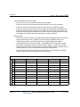
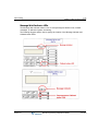
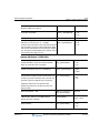
For example, the office work starts at 9:00 a.m. and finishes at 5:00 p.m.during week days. The
weekend starts at 5:00 p.m. from Friday to Sunday. In this case, the WEEKLY TIME TABLE can
be set as shown:
SAMPLE WEEKLY TIME TABLE
WEEKLY TBL: MON
D:09:00 N:17:00 W:
WEEKLY TBL: TUE
D:09:00 N:17:00 W:
WEEKLY TBL: WED
D:09:00 N:17:00 W:
WEEKLY TBL: FRI
D:09:00 N: W:17:00
WEEKLY TBL: SAT
D: N: W:00:00
WEEKLY TBL: SUN
D: N: W:00:00
Weekly Time Table -- this table is
executed by the System
Attendant and each Intercom
Tenancy Group Attendant.
Time zone of
DAY/NIGHT/WEEKEND for 7
days is programmed.
PGM 233 + VALUE (Weekly
Time table, Range = 0-5) +
FLEX 1 (Day Mode, Range =
FLEX 1 - FLEX 7) + FLEX 1
(Day Start, Night Start,
Weekend Start, Lunch Start,
Lunch End, Range = FLEX
1-FLEX 5) + Enter Time
(HH/MM) + [HOLD/SAVE]
WEEKLY TBL: THU
D:09:00 N:17:00 W:
VALUES -- Weekly Time Table (0-5)
- FLEX 1 (Day Mode F1-7)
F1 Monday
F2 Tuesday
F3 Wednesday
F4 Thursday
F5 Friday
F6 Saturday
F7 Sunday
- FLEX 1 (Start/End Time - HH/MM)
F1 - Day Start
F2 - Night Start
F3 - Weekend Start
F4 - Lunch Start
F5 - Lunch End
OPERATION / SETUP
To change the Day/Night Service mode:
1. Press [TRANS/PGM], then press 074] and select a ring mode (1-6).
2. Press [HOLD/SAVE] to activate ring mode.
NOTE:
Release 3.5
Time can be set for each mode automatically using the Weekly Time Table.
SBX IP Programming & Operations Guide
June 2010
Attendant Service
1-15
Chapter 1: Basic System Features
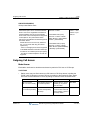
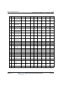
To change the time of a Day/Night Service mode:
Press PGM 233, then enter the times as needed.
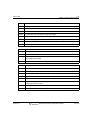
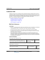
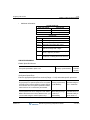
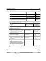
NOTE:
The default values of the Weekly Times are shown below. The first time settings
are for the Main Attendant (entry 00). Intercom Tenancy Group Attendants time
settings follow the Main Attendant (entry 01-15).
DATE
DAY
START TIME
LUNCH
START TIME
LUNCH
END TIME
NIGHT
START TIME
WEEKEND
START TIME
Mon
09:00
-:-
-:-
18:00
-:-
Tues
09:00
-:-
-:-
18:00
-:-
Wed
09:00
-:-
-:-
18:00
-:-
Thurs
09:00
-:-
-:-
18:00
-:-
Fri
09:00
-:-
-:-
-:-
18:00
Sat
-:-
-:-
-:-
-:-
00:00
Sun
-:-
-:-
-:-
-:-
00:00
Outgoing Access
The Attendant can take a particular CO line out of service. If this occurs, outgoing CO cannot
be made while incoming CO calls are not affected.
CONDITIONS
•
Any Attendant can use this feature.
•
The LED of the CO line Flex button which is with an "out" setting, flashes at the Attendant
station, but is solidly lit at other stations.
•
If a specific CO line is busy, it can still be taken out of service. The change in setting will
take effect after the CO line returns to an idle state.
OPERATION / SETUP
To set the CO line outgoing service:
1. Press [TRANS/PGM], then press 073.
2. Press the appropriate CO line Flex button.
A confirmation tone will sound when the status of the selected CO line is changed.
3. Press [SPEAKER] to finish.
To release the"out" setting:
1. Press [TRANS/PGM], then press 073.
2. Press the flashing CO line Flex button at the Attendant station.
Release 3.5
SBX IP Programming & Operations Guide
June 2010
Attendant Service
1-16
Chapter 1: Basic System Features
DSS/BLF Consoles
Attendant stations and other digital phones may be equipped with DSS/BLF consoles which
provide additional buttons for additional operation. The consoles are arranged as flexible
mapped units. They are initially assigned with programming as one of 3 maps. All buttons of all
maps are programmable.
The DSS/BLF consoles each require a separate line connection to the KSU, and take up a
station number.
CONDITIONS
•
There is no limit to the number of DSS/BLF consoles in a system.
•
The default value for DSS/BLF is as follows:
Release 3.5
Map 1
Flex 1 - Intrusion
Flex 2 - All Call Page
Flex 3 - Call Park 01
Flex 4 - Station Group 1
Flex 5 - Camp-on
Flex 6 - Internal All Call Page
Flex 7 - no default
Flex 8 - no default
Flex 9 - no default
Flex 10 - no default
Flex 11 - no default
Flex 12 - no default
Stations 100-135
Map 2
Stations 136-147
Map 3
Empty
SBX IP Programming & Operations Guide
June 2010
Attendant Service
1-17
Chapter 1: Basic System Features
ADMIN PROGRAMMING
Set Station ID Assignment
Station ID Assignment -- Station ID can be changed
to the desired value which is different from the
default value (e.g., normal DKTU /normal SLT).
PGM 110 + FLEX 1 +
(Station ID value) +
[HOLD/SAVE]
This identifies the type of telephone (digital, SLT
Doorbox/ICM Box) attached to the system.
VALUES -01 = DKTU
05 = ICM BOX
06 = Reserved
07 = SLT (DTMF)
08 = SLT (PULSE)
09 = Reserved
10 = Reserved
11 = Reserved
12 = SLT - CID (FSK)
13 = SLT - CID (DTMF)
14 = IP Phone
Set DSS/BLF ID Assignment
DSS -- one station can have up to 3 sequentially
numbered multiple DSS maps.
PGM 110 + FLEX 2 + (Station
ID value) + FLEX 2 + Station
Number + [HOLD/SAVE]
VALUES -02 = DSS MAP 1
03 = DSS MAP 2
04 = DSS MAP 3
ICM Box Music
An Attendant can select the music channel source that provides music to the intercom Box /
Doorbox.
NOTE:
Also see "Background Music (BGM)" on page 1-35, and "Music On Hold (MOH)" on page 1-74.
ADMIN PROGRAMMING
Enable Intercom Box Music Channel
ICM Box / Doorbox Music Channel -- establishes
which music channel will supply music to
Doorbox(es).
Release 3.5
PGM 171 + FLEX 3 + 0
(VALUE) + [HOLD/SAVE]
SBX IP Programming & Operations Guide
VALUES -0 = not assigned
1 = Int. Music
2 = External Music
3 = n/a
4-8 = SLT MOH
June 2010
Call Control
1-18
Chapter 1: Basic System Features
OPERATION / SETUP
To select the music source from an Attendant Station:
1. Press [TRANS/PGM], then press 075.
2. Enter the music source/channel (00-12):
Channel 00: No music
Channel 01: Internal music
Channel 02: External music
Channel 03: VMIB BGM
Channel 04-08: SLT MOH
NOTE:
As it is selected, the music source will be heard. However, if the music channel
has no music source, no music will be heard.
3. Press [HOLD/SAVE] to store the setting.
Station Feature Cancel
The Attendants can cancel features such as DND, Call Forward and pre-selected messages at
other stations.
OPERATION / SETUP
To disable active features for a station from an Attendant Station:
1. Press [TRANS/PGM], press 071.
2. Enter the appropriate station range.
3. Press [HOLD/SAVE] to store the setting.
Call Control
Account Code
Account codes are used to identify outgoing (external) calls for accounting and billing purposes.
A separate account code can be assigned to each station (up to 12 digits: 0 to 11) so that a
company can identify and bill (where applicable) calls made from each station.
IMPORTANT:
Release 3.5
An ACCOUNT CODE flex button must be programmed before certain aspects of
this operation can be performed (see below).
SBX IP Programming & Operations Guide
June 2010
Call Control
1-19
Chapter 1: Basic System Features
CONDITIONS
•
Each station can be assigned its own account code.
•
While entering the account code, the current call is put on hold.
•
The user may enter the account code before or after a call conversation is established.
ADMIN PROGRAMMING
Set the SMDR Account Enter Code
Use PGM 106, then Flex 7. For more details, refer to the SBX IP Installation Manual.
OPERATION / SETUP
To assign an ACCOUNT CODE flex button:
1. Press [TRANS/PGM].
2. Press the Flex button you want to assign as an ACCOUNT CODE button.
3. Press [TRANS/PGM], then press 80.
4. Press [HOLD/SAVE] to store the setting.
To enter an account code before accessing a CO line:
1. Press the programmed ACCOUNT CODE flex button.
2. Enter the account code (max of 12 digits), or press * button.
3. Intercom dial tone should be heard and a CO line is secured to make a call.
To enter an account code during a conversation:
1. While on a CO line call, press the ACCOUNT CODE flex button.
The other party will be put on hold.
2. Enter the account code (max of 12 digits).
3. Press the ACCOUNT CODE flex button.
You will be reconnected to the other party.
To enter an account code during a conversation (w/o using the ACCOUNT CODE flex button):
1. While on a CO line call, press [TRANS/PGM], then 550.
The other party will be put on hold.
2. Enter the account code (maximum 12 digits), or press * button.
You will be reconnected to the other party.
Release 3.5
SBX IP Programming & Operations Guide
June 2010
Call Control
1-20
Chapter 1: Basic System Features
Authorization Code
Authorization codes can be assigned to stations to give the users the ability to make calls on
restricted phone lines (overriding access restrictions). When a station is programmed to require
an Authorization Code, the assigned code must be entered in order to access a CO line.
CONDITIONS
•
To prevent restricted, unauthorized phone calls from being made, personal authorization
codes should be kept secure by the System Attendant and individual station users.
•
An authorization code must contain 3 to 11 digits.
•
Each station must have a different authorization code. An authorization code cannot be
assigned to more than one station.
•
Up to 200 authorization codes can be programmed on the system.
•
If Loop LCR ACNT is set on a station, the authorization code is required each time the
station dials the Loop LCR CO Access code.
•
An authorization code can be used for SMDR, DISA account codes.
•
A long beep after a number is dialed indicates the need to enter an authorization code.
•
Authorization codes are also used for mailbox passwords. Remote access of a mailbox
requires that a authorization code be programmed.
ADMIN PROGRAMMING
Access Authorization Code Table
Authorization code table entries consist of each station password and extra account
codes. The table entry from 001 to the maximum capacity of station numbers are saved
along with the password of each station. CO Line Groups can be marked to deny access
until a matched authorization code is entered. In this case, a DND warning tone is
provided when the CO Line Group access code is dialed.
There can be no duplicate entries. By default, Authorization Codes are not assigned. In an
SBX IP system, the total number of Authorization Codes is 200 entries.
Authorization code length can be programmed as 5 digits or variable length (3-11digits). If
5-digit authorization code usage is programmed, the authorization code works as 5-digit
length in admin program or features.
Release 3.5
SBX IP Programming & Operations Guide
June 2010
Call Control
1-21
Chapter 1: Basic System Features
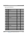
Enter the appropriate Bin number (001-200), then follow the procedure as shown:
Authorization Code Table -- if the dialed
Authorization code is verified, a CO dial tone
will be presented. Otherwise, an error tone
will be heard and access to the group will be
denied. Stations or Admin programming can
enter authorization codes. The Administrator
can see and change station passwords-no
duplicate entries. The total number of
Authorization Codes is 200 entries.
PGM 227 + FLEX 1 +
Authorization Code (3-11
digits; Range = 0-9) +
[HOLD/SAVE]
VALUES -Default = Not Assigned
Day COS of Authorization Code -- Day COS
of stations can only be viewed; COS for
extra entries can also be assigned.
PGM 227 + FLEX 2 +
Class of Service Value +
[HOLD/SAVE]
VALUES -Range = 1-9
Night COS of Authorization Code -- Night
PGM 227 + FLEX 3 +
COS of stations can only be viewed; Night
Class of Service Value +
COS for extra entries can also be assigned. [HOLD/SAVE]
VALUES -Range = 1-9
Authorization codes can be
programmed as 5 digits or
flexible length (3-11 digits);
refer to PGM 161 - FLEX21
Set DISA Account Code
Use PGM 141 … see page 1-130.
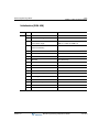
Access CO Line Group Account
CO Line Group Account -- if this value is set to ON, the CO Line
user will be prompted to enter an authorization code to access
this CO Line.
PGM 141 + FLEX 9 + 0
(Off) + [HOLD/SAVE]
VALUES -0 = Off
1 - On
Set Loop LCR Account Code
Loop LCR Account Code -- if value is set to ON, the Station
User must enter an Account Code to use Loop LCR.
PGM 111 + FLEX 16 + 0
(Off) + [HOLD/SAVE]
VALUES -0 = Off
1 = On
Set 5 Digit Authorization Code Usage
5 Digits Authorization Code Usage -- if value is set to ON,
Authorization code is programmed as 5 digits fixed length.
Under this mode, 5 digits of the authorization code should be
entered when related features are activated. If this value is set
to OFF, Variable Authorization code (3-11 digits) is used.
Release 3.5
PGM 161 + FLEX 21 + 0
(Off) + [HOLD/SAVE]
SBX IP Programming & Operations Guide
VALUES -0 = Off
1 = On
June 2010
Call Control
1-22
Chapter 1: Basic System Features
Enable Station Account
Forced Station Account Code -- if this value is set to ON, a
password is needed to access an outgoing CO line.
PGM 112 + FLEX 20 + 0
(Off) + [HOLD/SAVE]
VALUES -0 = Off
1 = On
OPERATION / SETUP
To access a CO line using an authorization code:
1. When a long warning tone sounds after dialing, enter the designated authorization
code.
2. Press # to complete the entry.
NOTE:
If a five digit authorization code type (see ADMIN PROGRAMMING), you do
not need to press #. If the code entered is valid/correct, the CO line will be
connected. Otherwise, an error tone will be presented.
To register the authorization code on a station:
1. Press [TRANS/PGM], then 31.
2. Enter the authorization code, then press #.
NOTE:
If a five digit authorization code type (see ADMIN PROGRAMMING), you do
not need to press #.
3. Press [HOLD/SAVE] to store the changes.
To change the authorization code at a station:
1. Press [TRANS/PGM], then 32.
2. Enter the current authorization code.
3. Enter in the new authorization code.
4. Press [HOLD/SAVE] to store the change.
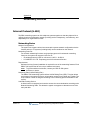
Automatic Call Release
When a station does not complete a connection on an outgoing CO line, or receives no answer
on an intercom call, the system will disconnect the call based on assigned Auto Release Timer.
CONDITIONS
•
If a user station is in speaker mode, the Station returns to idle, otherwise the station will
receive an error tone if using the handset.
•
An Intercom call in Hands-Free mode is answered, Station Auto Release will not be
activated.
Release 3.5
SBX IP Programming & Operations Guide
June 2010
Call Control
1-23
Chapter 1: Basic System Features
•
When the Automatic Release time is set to 0, the feature is not activated.
•
If a call is dialed without lifting the handset, and the Auto Release timer expires, the call
will be canceled. In addition, the station will automatically return to an idle state.
•
If a call is dialed using the handset, and the Auto Release timer expires, the call will be
canceled. An error tone will sound.
ADMIN PROGRAMMING
Set Automatic CO Release Timer
Automatic CO Release Timer -- Uncompleted CO line
calls will automatically be released when the timer
expires.
PGM 180 + FLEX 14
VALUES -+ 030 (seconds, 3
Range = 020-300
digits) + [HOLD/SAVE]
Set Station Auto Release Timer
Station Auto Release Timer -- If a station user hears a
ring back tone and no action is taken within the
designated time, the station will be released.
PGM 182 + FLEX 5 +
060 Value (1 sec, 3
digits) + [HOLD/SAVE]
VALUES -Range = 020-300
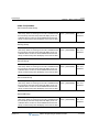
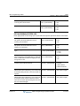
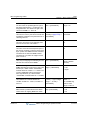
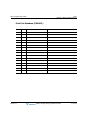
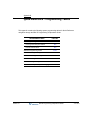
Class Of Service (COS)
Each station and CO line may be assigned different classes to either allow or restrict call
service. The level of COS assignments are programmed at each station and each CO line.
CONDITIONS
COS Rules
•
In STA COS 7, no dialing is allowed on CO lines.
•
In CO COS 5, STA COS 1-6 is ignored, and there is no restriction on access to CO lines.
•
CO COS 4, STA COS 1-6 are ignored, and long distance calls are not allowed; max. 8
digits may be dialed.
•
CO COS 1 is restricted by the STA COS.
•
CO COS 2 and STA COS 2/4 are restricted by Exception Table A.
•
There is no restriction in STA COS 1/3.
•
In STA COS 5, long distance calls are not allowed; max. 8 digits can be dialed.
Release 3.5
SBX IP Programming & Operations Guide
June 2010
Call Control
1-24
Chapter 1: Basic System Features
CO lines Allow/Deny Restriction Rules
•
If there are no entries, no restriction is provided by the table.
•
If there are entries in the Deny table, then the restriction is on a Deny Only basis.
•
If there are entries in the Allow table, then the restriction is on an Allow Only basis.
•
If there are entries in both the Allow and Deny Tables, the Allow Table is searched first. If a
dialed number matches an entry in the Allow Table, the call is allowed. If a match is not
found, then the Deny Table is searched. If a match is found in the Deny Table, the number
is restricted. If no match is found in either table, the number is allowed.
General Rules
•
PBX Access Codes: There are five (2-digit) PBX access codes that allow you to enter the
system and access a CO line via PBX. A CO line marked as a PBX line will not be
controlled by any station or CO line COS until a recognized PBX code is dialed.
•
Canned Restrictions: Canned, Restricted 1: Long distance call is not allowed. Canned,
Restricted 2: Long distance call is not allowed. Max. 8 digits (*, 0, # can not be dialed).
•
Exception Tables A and B: These are the two exception tables for COS. Each table has 20
"allow" codes and 10 "deny" codes. Each code may have eight entries.
•
CO Call Toll Checks: If an incoming CO Call Toll Check is set, the COS rule is applied
when the station dials after answering an incoming CO call.
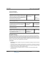
CO LINE COS
1
S
T
A
T
I
O
N
2
3
4
5
1
Unrestricted
Unrestricted
Unrestricted
Canned Restricted 2 Unrestricted
2
Table A
Table A
Unrestricted
Canned Restricted 2 Unrestricted
3
Table B
Unrestricted
Table B
Canned Restricted 2 Unrestricted
4
Table A, B
Table A
Table B
Canned Restricted 2 Unrestricted
5
Canned Restricted 1 Canned Restricted 1 Canned Restricted 1 Canned Restricted 2 Unrestricted
6
Canned Restricted 2 Canned Restricted 2 Canned Restricted 2 Canned Restricted 2 Unrestricted
7
Intercom Only
C 8 Table C
O 9 Table D
S
10 Table C, D
11 Table A, B, C, D
Release 3.5
Intercom Only
Intercom Only
Intercom Only
Table C
Unrestricted
Canned Restricted 2 Unrestricted
Table D
Unrestricted
Canned Restricted 2 Unrestricted
Table C, D
Unrestricted
Canned Restricted 2 Unrestricted
Table A, B, C, D
Unrestricted
Canned Restricted 2 Unrestricted
SBX IP Programming & Operations Guide
Intercom Only
June 2010
Call Control
1-25
Chapter 1: Basic System Features
COS 1
There is no restriction to dial.
COS 2
Monitored by Exception Table A
COS 3
Monitored by Exception Table B
COS 4
Monitored by Exception Table A & B
COS 5
Long distance call is not allowed; longer than 8 digits
COS 6
Long distance call is not allowed; max. 8 digits may be dialed
COS 7
Only intercom, paging and emergency calls are allowed; no dialing allowed on CO lines
COS 8
Monitored by Exception Table C
COS 9
Monitored by Exception Table C
COS 1
There is no restriction. Monitored by STA COS.
COS 2
Monitored by Exception Table A & STA COS 2/4.
COS 3
Monitored by Exception Table B & STA COS 2/4
COS 4
Long distance call is not allowed for all STA COS;
max. 8 digits may be dialed
COS 5
Overrides STA COS 2, 3, 4, 5, 6, no COS restriction
COS 1
There is no restriction to dial
COS 2
Monitored by Exception Table A
COS 3
Monitored by Exception Table B
COS 4
Monitored by Exception Table A & B
COS 5
Long distance call is not allowed; longer than 8 digits
COS 6
Long distance call is not allowed; only max. 8 digits may be dialed
COS 7
Only intercom, paging and emergency call are allowed;
no dialing allowed on CO lines
COS 8
The assignments in the Exception Table C are monitored for allow and deny numbers
COS 9
The assignments in the Exception Table D are monitored for allow and deny numbers
Release 3.5
SBX IP Programming & Operations Guide
June 2010
Call Control
1-26
Chapter 1: Basic System Features
ADMIN PROGRAMMING
Set Station COS
Enter the appropriate station range, then follow the procedure as shown:
Station COS -- each station is assigned a Class Of
Service (COS) that determines the station toll
restriction for day and night operation (refer to Table).
On a particular call, the CO COS is combined with
Station COS to determine the restriction. COS for all
stations at day and night operation are 1 by default.
The weekend COS is the same as night COS.
STA COS
Release 3.5
PGM 116 + FLEX 1 (Day) +
1 (sta COS range = 1-11) +
[HOLD/SAVE]
VALUES -FLEX 1 = Day
FLEX 2 = Night
PGM 116 + FLEX 2 (Night)
+ 1 (sta COS range = 1-11)
+ [HOLD/SAVE]
DESCRIPTION
1
No restrictions are placed at the station for dialing.
2
Assignments in Exception Table A are monitored for Allow and Deny numbers.
3
Assignments in Exception Table B are monitored for Allow and Deny numbers.
4
Assignments in Exception Tables A & B are monitored for Allow and Deny numbers.
5
Leading digit dialed cannot be a long distance code. The dialed digits can be longer than 7
digits. There is no restriction for the number in the Canned Toll Table.
6
Leading digits cannot be a long distance code. Only eight digits maximum can be dialed.
(There is no restriction for the number in the Canned Toll Table.)
7
Intercom and paging calls are allowed. No dialing is allowed on CO lines. ICM boxes are
assigned with this COS.
8
Assignments in Exception Table C are monitored for allow and deny numbers.
9
Assignments in Exception Table D are monitored for allow and deny numbers.
10
Assignments in Exception Tables C & D are monitored for allow and deny numbers.
11
Assignments in Exception Tables A, B, C, & D are monitored for allow and deny numbers.
SBX IP Programming & Operations Guide
June 2010
Call Control
1-27
Chapter 1: Basic System Features
Set CO Line COS
CO COS -- COS is assigned to each CO
line.
PGM 141 + FLEX 2 + 1
(COS) + [HOLD/SAVE]
VALUES -1 = No restriction
2 = Exception Table A governs
3 = Exception Table B governs
4 = Restricts Long Distance Code
5 = Overrides Station COS 2-6
Set CO-to-CO COS
Day COS -- Class-of-Service of Day Mode
PGM 166 + FLEX 1 + 07 VALUES -(VALUE) + [HOLD/SAVE] 01-11
Night/Weekend COS -- Class-of-Service of Night/Weekend
Mode
PGM 166 + FLEX 2 + 07 VALUES -(VALUE) + [HOLD/SAVE] 01-11
Access Toll Exception Table
The Allow/Deny Tables are organized into 2 sets of tables to support 2 different toll plans at one
installed site. Each allow/deny table may contain up to 30 number strings. All bins of allow and
deny tables have no entries by default. Each number string can contain up to 14 entries
including any number 0-9, *, #, "Don't care."
The following rules should be remembered when setting up the Allow/Deny Tables:
•
If the tables have no entries, no restriction is applied.
•
If entries are made in the allow table and only there, then only those numbers are allowed.
•
If entries are made in the deny table and only there, then only those numbers are denied.
•
If there are entries in both tables, the allow table is searched at first and if number is found,
it is allowed. If not found, the deny table is searched and if number is found, it is denied. If
it is not found in either table, it is allowed.
RULE
ENTRY
ALLOW
Release 3.5
CONDITIONS & RESULT
DENY
ALLOW TABLE
DENY TABLE
1
Not Exist
Not Exist
No Restriction
No Restriction
2
Exist
Not Exist
Found - allowed
Not found - denied
--
3
Not Exist
Exist
--
Found - denied
Not found - allowed
4
Exist
Exist
Found - allowed
Not found - check deny table
Found - denied
Not found - allowed
SBX IP Programming & Operations Guide
June 2010
Call Control
1-28
Chapter 1: Basic System Features
Allow Table A - -used to check whether the dialed
digits by COS 2 and COS 4 station is matched with
the allowed toll pass digits. NOTE: Allow table A is
only used when the COS of dialed station is COS 2
or 4.
PGM 224 + FLEX 1 + VALUE
(refer to Allow Table) + Allow
Number (max 14 digits; 0-9, #,
*, Don't Care) + [HOLD/SAVE]
VALUES -Range = 01-30
Deny Table A -- used to check whether the dialed
digits by COS 2 and COS 4 station is matched with
the denied toll pass digits. NOTE: Deny table A is
only used when the COS of dialed station is COS 2
or 4.
PGM 224 + FLEX 2 + VALUE
(refer to Deny Table) + Deny
Number (Max 14 Digits; 0-9, #,
*) + [HOLD/SAVE]
VALUES -Range = 01-30
Allow Table B -- used to check whether the dialed
digits by COS 3 and COS 4 station is matched with
the allowed toll pass. NOTE: Allow table B is only
used when the COS of dialed station is COS 3 or 4.
PGM 224 + FLEX 3 + VALUE
(refer to Allow Table) + Allow
Number (Max 14 Digits; 0-9, #,
*) + [HOLD/SAVE]
VALUES -Range = 01-30
Deny Table B -- used to check whether the dialed
digits by COS 3 and COS 4 station is matched with
the denied toll pass digits. NOTE: Deny table B is
only used when the COS of dialed station is COS 3
or 4.
PGM 224 + FLEX 4 + VALUE
(refer to Deny Table) + Deny
Number (Max 14 Digits; 0-9, #,
*) + [HOLD/SAVE]
VALUES -Range = 01-30
Allow Table C -- used to check whether the dialed
digits by COS 8 station is matched with the allowed
toll pass digits. NOTE: Allow table A is only used
when the COS of dialed station is COS 8.
PGM 224 + FLEX 5 + VALUE
(refer to Allow Table) + Allow
Number (Max 14 Digits; 0-9, #,
*) + [HOLD/SAVE]
VALUES -Range = 01-50
Deny Table C -- used to check whether the dialed
digits by COS 8 station is matched with the denied
toll pass digits. NOTE: Deny table A is only used
when the COS of dialed station is COS 8.
PGM 224 + FLEX 6 + VALUE
(refer to Deny Table) + Deny
Number (Max 14 Digits; 0-9, #,
*) + [HOLD/SAVE]
VALUES -Range = 01-50
Allow Table D -- used to check whether the dialed
digits by COS 9 Station is matched with the allowed
toll pass.
NOTE: Allow table B is only used when the COS of
dialed station is COS 9.
PGM 224 + FLEX 7 + VALUE
(refer to Allow Table) + Allow
Number (Max 14 Digits; 0-9, #,
*) + [HOLD/SAVE]
VALUES -Range = 01-50
Deny Table D -- used to check whether the dialed
digits by COS 9 Station is matched with the denied
toll pass digits. NOTE: Deny table B is only used
when the COS of dialed station is COS 9.
PGM 224 + FLEX 8 + VALUE
(refer to Deny Table) + Deny
Number (Max 14 Digits; 0-9, #,
*) + [HOLD/SAVE]
VALUES -Range = 01-50
If programming FLEX 1-4, you must re-enter PGM 224 to gain access to programming of FLEX 5-8 and vice versa.
Release 3.5
SBX IP Programming & Operations Guide
June 2010
Call Control
1-29
Chapter 1: Basic System Features
Access Canned Toll Tables
In addition to the basic toll restrictions, stations within COS 5 or 6 are subject to dial restrictions
based on the Canned Allow and Deny Tables. This program permits entries in the Canned Toll
Tables. Both the Allow and Deny table have 20 bins up to 14 digits.
VALID DATA
FUNCTION
LCD DISPLAY
0-9, *, #
Number
as dialed
[DND/FWD]
Don’t Care
"D"
Allow Table -- used to check, whether the dialed
digits by COS 5 and COS 6 station is matched with
the allowed toll pass digits. NOTE: Allow table of
canned toll is only used when the COS of dialed
station is COS 5 or 6.
PGM 225 + FLEX 1 + VALUE
(refer to Allow Table) + Allow
Number (Max 14 Digits; 0-9, #, *)
+ [HOLD/SAVE]
VALUES -Range = 01-20
Deny Table -- used to check whether the dialed
digits by COS 5 and COS 6 station is matched with
the denied toll pass digits. NOTE: Deny table of
canned toll is only used when the COS of dialed
station is COS 5 or 6.
PGM 225 + FLEX 2 + VALUE
(refer to Deny Table) + Deny
Number (Max 14 Digits; 0-9, #, *)
+ [HOLD/SAVE]
VALUES -Range = 01-20
Enable Incoming Toll Check
Incoming Toll Check -- if this value is set to ON, the system
checks for tolls applied to incoming CO calls.
PGM 161 + FLEX 16 + 0
(OFF) + [HOLD/SAVE]
VALUES -0 = Off
1 = On
System Speed Zone
System Speed Zones consist of Speed bins & stations. Toll checks based on COS can be
applied to zones. Up to 10 speed number zones can be defined. Only stations allocated to
zones can access these bins. Speed bins not allocated to zones can be accessed by all stations
and no toll checks are applied.
ADMIN PROGRAMMING
Enable Speed Dial Access
Use PGM 112, then FLEX 9 … see page 1-168.
Assign System Speed Zone
Use PGM 232 … see page 1-168.
Release 3.5
SBX IP Programming & Operations Guide
June 2010
Call Control
1-30
Chapter 1: Basic System Features
Enable CO Dial Tone Detect
CO Dial-Tone Detect -- when speed dial is activated, if this
value is set to ON, the system will detect a dial tone using CPT
instead of the pause timer.
PGM 160 + FLEX 6 + 0
(OFF) + [HOLD/SAVE]
VALUES -0 = OFF
1 = ON
Walking Class of Service (Walking COS)
This feature allows temporary override of the toll restriction to allow toll call from previously toll
restricted phones. The authorization code can be used as a verified account code for SMDR.
CONDITIONS
•
This feature can be used on both digital and SLT phones.
•
This feature is available on a per-use basis only. The original programmed station COS
will be used when activating Walking COS, disconnecting a call, or pressing
[TRANS/PGM] to hold the call (and seize another line).
•
When a wrong number is dialed, press [FLASH] to dial again without having to access
another idle CO line.
•
The fee for a call with Walking COS will be charged according to the station authorization
code, not the actual station.
•
When a user tries to use Walking COS at a station set to COS 7 (with temporary COS),
the call will follow the original COS of the station.
ADMIN PROGRAMMING
Access the Authorization Code Table
Use PGM 227 … see page 1-20.
OPERATION / SETUP
To activate Walking COS:
1. Press [TRANS/PGM], then press 23.
A confirmation tone sounds.
2. Enter the authorization code; the intercom dial tone sounds and the used extension
COS is temporarily changed. (Note: A CO call can only be placed one time.)
To program a Walking COS flex button:
1. Press [TRANS/PGM], then the applicable Flex button.
2. Press [TRANS/PGM], then 23.
3. Press [HOLD/SAVE] to store the setting.
Release 3.5
SBX IP Programming & Operations Guide
June 2010
Call Handling
1-31
Chapter 1: Basic System Features
Call Handling
Alarm
This feature allows you to set up an external contact to create an internal alarm. When the
contact is established and programmed, an alarm tone (single tone repeated per 1-min. interval
or a continuous tone) can be sent to designated stations within the system.
CONDITIONS
•
An external contact should be connected to the alarm input.
•
The alarm contacts should be dry (no voltage/current source connected).
•
Single Line Telephones (SLTs) cannot receive alarm signals.
•
An Alarm Reset can be programmed on a Flex button.
ADMIN PROGRAMMING
Enable Alarm
Alarm Enable -- if value is set to ON, Alarm is available.
PGM 163 + FLEX 1 + 0
(Off) + [HOLD/SAVE]
VALUES -0 = Off
1 = On
PGM 163 + FLEX 2 + 1
(Close) + [HOLD/SAVE]
VALUES -0 = Open
1 = Close
Set Alarm Contact Type
Alarm Contact Type -- if value is set to OPEN, when alarm
relay is open, then alarm ring is provided.
Select Alarm Mode
Alarm Mode -- if value is set to DOOR BELL, alarm signal is
provided only one time. If value is set to ALARM, alarm
signal is provided continuously depending on Alarm Signal
Mode (Flex 4).
Release 3.5
PGM 163 + FLEX 3 + 1
(Alarm) + [HOLD/SAVE]
SBX IP Programming & Operations Guide
VALUES -0 = Door Bell
1 = Alarm
June 2010
Call Handling
1-32
Chapter 1: Basic System Features
Select Alarm Signal Mode
Alarm Signal Mode -- if value is set to REPEAT, the Alarm
Signal is repeated until Alarm is reset.
PGM 163 + FLEX 4 + 1
VALUES (Repeat) + [HOLD/SAVE] 0 = Once
1 = Repeat
OPERATION / SETUP
To terminate the alarm signal from an Attendant Station:
Press 565.
A confirmation tone sounds, and the alarm signal will be terminated at all assigned
stations.
Automatic Incoming Fax Transfer
The system automatically determines if an incoming call from the designated analog CO line is
for a fax or for a speech terminal by detecting the tone of the call (that is, 1100Hz, 0.5s ON/3s
OFF repeated). When the system detects a fax tone from the incoming line within the
predetermined time, the system transfers the call to the appropriate fax station. If the fax tone
is not detected within the predetermined time, the system interprets this as a normal phone call
(no fax), so the call is transferred to the specified station.
IMPORTANT:
Only analog lines are enabled for using this feature.
CONDITIONS
•
Only one CO line can be designated as a fax CO line. If a fax CO line is not programmed,
Automatic Fax Transfer cannot be activated.
•
Station 17 is pre-programed station for fax transfers. Therefore, the fax machine should be
connected to the port for Station 17.
•
If the fax CO line is not answered within the fax CO call time, the incoming call will be
disconnected.
•
An outside caller connected to the fax CO line will hear a ring back tone when the system
detects a fax tone.
•
To transfer calls from the fax to a fax station, do not assign CO ring to the fax Station 17.
•
If a CO line is programmed for DISA, as well as for Automatic Fax Transfer, incoming calls
from that CO line are served as DISA calls. Therefore, if a user wants to call the fax
station, they will need to call Station 17 via the DISA call.
•
When the fax machine goes idle after a fax call, the associated CO line is released.
•
If the fax CO line is disconnected during a fax call, the CO line is released, and the fax
machine returns to an idle state.
Release 3.5
SBX IP Programming & Operations Guide
June 2010
Call Handling
1-33
Chapter 1: Basic System Features
ADMIN PROGRAMMING
Set Auto Fax Transfer CO
Auto Fax Transfer CO -- if an Auto FAX CO line is
programmed, the system answers and detects the FAX
calling tone (1100Hz, 0.5sec ON/3sec OFF repeat tone)
from an incoming analog CO line. The system will route
this call to the last SLT port on basic MBU when tone is
detected within the programmed time.
PGM 161 + FLEX 17 +
Value (CO Line number)
+ [HOLD/SAVE]
VALUES -Range = 01-36
(avail for
Analog CO line)
Set Fax Tone Detect Timer
Fax Tone Detect Timer -- designates the amount of
time allowed to detect a FAX tone from the FAX CO
line before the call is routed to the ring assigned
Station for FAX CO line
PGM 182 + FLEX 13 + 05
seconds (2 digits) +
[HOLD/SAVE]
VALUES -Range = 01-10 secs
(5 sec is suggested)
Set Fax CO Call Timer
Fax CO Call Timer -- designates the amount of time
allowed to connect a call when a FAX tone is detected
from a FAX CO line; the call will attempt to be routed
to the appropriate FAX station.
Enter Bin number (01-10),
then PGM 182 + FLEX 14
+ 1 minute (1 digit) +
[HOLD/SAVE]
VALUES -Range = 1-5 mins
Automatic Privacy
By default, all conversations (on CO lines, the intercom, and conferences) are protected by
privacy (Automatic privacy). This prevents one station from accessing a line to listen in on a
conversation. However, this feature can be disabled by the station user as needed (via the HTP
feature). To allow a user to have the ability to enable or disable Automatic Privacy, the System
Attendant must make such a configuration in the system.
CONDITIONS
•
If Automatic Privacy is enabled, a busy tone is heard when an attempt is made to access a
busy CO line.
•
If Automatic Privacy is disabled, intruding station is connected to conversation in progress.
•
When Automatic Privacy is disabled, privacy is still active for Intercom & Conference calls.
•
A station can only override a privacy-disabled station.
•
The station with Privacy disabled will hear an "intrustion" tone when another station
accesses the line.
Release 3.5
SBX IP Programming & Operations Guide
June 2010
Call Handling
1-34
Chapter 1: Basic System Features
ADMIN PROGRAMMING
Enable Auto Privacy
Auto Privacy -- if value is set to ON, a call is protected from
override regardless of Station Override Privilege (PGM 113 FLEX 4).
PGM 161 + FLEX 5 + 1
(On) + [HOLD/SAVE]
VALUES -0 = Off
1 = On
PGM 161 + FLEX 6 + 1
(On) + [HOLD/SAVE]
VALUES -0 = Off
1 = On
Set Privacy Warning Tone
Privacy Warning Tone -- if value is set to ON, a privacy
warning tone will be heard when a call is overridden.
Enable Override Privilege
Override Privilege -- if value is set to ON, the station user can
override a CO Call.
PGM 113 + FLEX 4 + 0
VALUES -(Disable) + [HOLD/SAVE] 0 = Disable
1 = Enable
Barge In
The Barge In feature permits one station (with authorization) to intrude into existing
outside/internal calls on other stations. Barging In actually establishes a conference call.
There are two Barging In modes:
•
Monitor - allows one station to listen to (but not participate in) an existing conversation.
•
Speech - allows one station to join an existing conversation.
CONDITIONS
•
This feature is only supported for digital phones that have (three) soft buttons.
•
This feature is only available for a called party in "talk state" on a CO Line or intercom.
•
An Emergency Supervisor is only connected to an Attendant Station when the Executive
Station is called.
Release 3.5
SBX IP Programming & Operations Guide
June 2010
Call Handling
1-35
Chapter 1: Basic System Features
ADMIN PROGRAMMING
Enable Barge In mode
Barge In Mode -- if in monitor mode, a barge in station
can only hear the current conversation. If in speech
mode, a barge in station can converse.
PGM 113 + FLEX 13 + 0
(Value) + [HOLD/SAVE]
VALUES -0 = Disable
1 = Monitor mode
2 = Speech mode
OPERATION / SETUP
To use the Monitor mode:
When you receive the busy tone at a station, press the "MONITOR" soft button.
(Those already participating in the conversation hear a warning tone, and you can listen
into the conversation.)
To use the Speech mode:
While you are listening to the existing conversation, press the "JOIN" soft button.
(Those already participating in the conversation hear a warning tone, and you can
participate in the conversation.)
To cancel the Monitor or Speech mode:
Press the "DROP" soft button or hang up.
Background Music (BGM)
A station user can listen to Background Music (BGM) through the speaker while the handset is
on-hook, and the line is in an idle state.
- Music can be enabled on an external page port from the Attendant Station.
- Background music can be transmitted through the intercom box at an Attendant Station.
CONDITIONS
•
•
•
•
•
•
•
Release 3.5
Music from the source is heard over the station speaker and will be shut-off automatically
when a call or paging announcement is received, or when the station is taken off-hook.
When lifting handset or pressing [SPEAKER] at a station, music is automatically shut-off.
When external music is assigned, the music source should be connected to the MBU.
The same music source can be used with MOH (see 1-74).
Press the volume buttons to adjust the volume while the background music is heard.
Press the [DND/FWD] to block BGM to block an intercom box / Doorbox.
Also see ICM Box Music on page 1-17, and Music On Hold (MOH) on page 1-74.
SBX IP Programming & Operations Guide
June 2010
Call Handling
1-36
Chapter 1: Basic System Features
ADMIN PROGRAMMING
Choose Background Music Type
BGM Type -- This is Background Music type (internal,
external, or SLT).
PGM 171 + FLEX 1 + 1
(Value) + [HOLD/SAVE]
VALUES -0 = not assigned
1 = Int. Music
2 = Ext. Music
3 = n/a
4-8 = SLT MOH
OPERATION / SETUP
To enable background music at a station:
Press [TRANS/PGM], then press 73 to hear the music through the speaker.
To transmit background music on an external page port at the Attendant Station:
1. Press [TRANS/PGM], then press 076 (External port).
2. Enter the background music channel number.
The music will play.
3. Press [HOLD/SAVE] to store the setting.
After hearing the confirmation tone, the station should go to an idle state, and the
selected background music will be transmitted on an external port.
To transmit background music through the intercom box at an Attendant Station:
1. Press [TRANS/PGM], then press 075.
2. Enter the background music channel number.
3. Press [HOLD/SAVE] to store the setting.
After the confirmation tone is sounded, the station will go into an idle state. The
selected background music will be transmitted over the intercom box.
Release 3.5
SBX IP Programming & Operations Guide
June 2010
Call Handling
1-37
Chapter 1: Basic System Features
Call Log (Models 7208D/7224D only)
The Call Log feature enables the station user to view a log of the last (15 to 50) incoming,
outgoing, and lost calls. The user can scroll through the list of numbers stored, select the
appropriate number, and activate a redial to that number.
The log includes the dialed number (CLI), the time, the date, and Station/System Speed name
of the call (if applicable). It is stored on the MBU, so it is retained even if the station is unplugged
or replaced.
IMPORTANT:
This feature is only available if a flex button has been programmed.
CONDITIONS
•
To use this feature, a flex button must be programmed for the call log.
•
A user can program the Call Log List number (in the range of 15 to 50 - per station).
•
When the Call Log List number is programmed, the All Call Log database will be
initialized.
•
The maximum Call Log List items allowed per system is 500.
•
The system assigns the Call Log list in order from the first available port.
•
CLI MSG-Wait must be enabled in order to use the Lost Call Log.
ADMIN PROGRAMMING
Set Call Log List Number
Call Log List Number -- sets the number of Call Log
Lists per Station.
PGM 160 + FLEX 19 + Value VALUES -(10, 2 digits) + [HOLD/SAVE] Range = 10-50
Enable CLI Message Wait
Use PGM 114, then FLEX 4 … see page 1-136.
OPERATION / SETUP
To program a Call Log flex button:
1. Press [TRANS/PGM], then press the flex button to be assigned for the Call Log
feature.
2. Enter the Call Log code, then press [TRANS/PGM].
3. Press 57.
4. Press [HOLD/SAVE] to store the setting.
Release 3.5
SBX IP Programming & Operations Guide
June 2010
Call Handling
1-38
Chapter 1: Basic System Features
To use the Call Log feature:
1. Press the programmed {CALL LOG} button.
2. Use the up/down navigation buttons to scroll through the numbers to locate received
calls, dialed calls, and lost calls, as needed.
3. When the CLI of the appropriate number is displayed, press OK button.
The system will establish a call to that number.
4. Select the Lost Call Menu to view CLI MSG-Wait numbers.
A number in the Lost Call list can be answered, deleted, or saved by pressing the
Select soft button.
Call Screening
When a call is sent to a voice mailbox, the station associated with that mailbox can press a
pre-programmed button to listen to the caller leaving the voice mail message. If the mailbox
owner decides to speak with the caller, the owner can press the pre-programmed button to be
connected to the caller.
Notification Methods
Two methods of notification are available: Ring Mode or Speaker Mode. The pre-programmed
button type (Ring Mode or Spkr Mode) defines the operation mode.
EX. -- Station A user places their phone in the answering machine mode by pressing the
flexible button programmed on the telephone. The button light is solid red. When an
incoming CO call rings at a station and forwards (except busy type) to the station's voice
mailbox, the following will occur:
- In RING MODE, the preprogrammed answering machine flexible button flashes red
while the caller is in the owner's mailbox. The mailbox owner presses the
pre-programmed flashing button and the audio is broadcast over the speaker of the
keyset. The mute key is enabled on the keyset at this point. The LED light is solid
green.
-
In SPKR MODE, the voice mail message is broadcast over the speaker. The mute key
is enabled on the keyset and the LED light is solid green.
CONDITIONS
•
The user must have a digital Keyset.
•
Keyset users must pre-program a CALL SCREENING flexible button.
•
An idle station can press the flexible button to go to the inactive mode. The LED
extinguishes and No Answer calls are presented to the station.
•
When button is programmed at the station, it is in the inactive mode (LED extinguishes).
Release 3.5
SBX IP Programming & Operations Guide
June 2010
Call Handling
1-39
Chapter 1: Basic System Features
•
When the owner presses the pre-programmed button to be connected to the caller, the
voice message will not be saved.
•
This is available for No Answer forward type.
ADMIN PROGRAMMING
Enable VMIB Access
Use (PGM 113), then FLEX 2 … see page C-21.
Assign Flex Button/Station Programming Button
Use PGM 115 … see page 1-55.
OPERATION / SETUP
To set the Operation Mode:
1. Press [TRANS/PGM]
2. Press the desired flexible button for programming.
3. Dial [XXX] + [0] to select the ring mode or dial [XXX] + [1] to select the speaker mode.
A confirmation tone sounds.
Camp-on
Camp-On allows you to set your phone to automatically call back a station that is busy. The
camp-on tone sounds at the busy station and the [HOLD/SAVE] LED flashes to notify the user
of the waiting call.
NOTE:
An SLT user can notify a busy station of a CO or intercom call waiting.
CONDITIONS
•
Camp-on is not applied to a station which is in DND mode, on a conference call, or placing
a page.
•
The Attendant can override a station using the Camp-On feature.
•
If the Stop Camp-on Tone is enabled, the Camp-On tone will not sound.
ADMIN PROGRAMMING
Enable Stop Camp-on Tone
Stop Camp-on Tone -- if value is set to ON, Camp on Tone is
not heard.
Release 3.5
PGM 112 + FLEX 15 + 0 VALUES -(Disable) + [HOLD/SAVE] 0 = Disable
1 = Enable
SBX IP Programming & Operations Guide
June 2010
Call Handling
1-40
Chapter 1: Basic System Features
Enable Voice-Over (including SLT)
Voice Over -- if value is set to ON, the busy Station can talk
alternately between two calling or called parties.
PGM 113 + FLEX 6 + 0
VALUES -(Disable) + [HOLD/SAVE] 0 = Disable
1 = Enable
OPERATION / SETUP
To activate Camp-on when an Intercom busy tone is heard:
Press * or the last digit of the busy station.
-orPress the busy DSS flex button.
-orPress the flex button assigned as {Camp-On}.
To answer a Camp-on call when receiving the Intercom busy tone:
1. When Camp-on tone sounds, press [HOLD/SAVE].
The active CO line is placed on Exclusive Hold (see "Hold" on page 1-184), and the
camped-on call is connected.
2. Press [HOLD/SAVE] to toggle between parties.
To activate Camp-On on an SLT when receiving a busy tone:
1. Go Off-hook, then press *, or enter last digit of the dialed station number.
2. When answered, announce the call for a supervised transfer
-orWhen answered, hang up without announcing the call for a blind transfer.
To answer Camp-On on an SLT:
1. When Camp-on tone sounds, perform a hook-flash, then enter 560.
The SLT station will connect to the camped-on call.
2. Perform a hook-flash, then press 56 again, to connect to the original station call.
To assign the {Camp-On} button as a flex button:
1. Press [TRANS/PGM], then press the flex button to be assigned to {Camp-On}.
2. Press [TRANS/ PGM], then press 85.
3. Press [HOLD/SAVE] to save the setting.
Release 3.5
SBX IP Programming & Operations Guide
June 2010
Call Handling
1-41
Chapter 1: Basic System Features
Chime Bell
A flex button can be set up to activate a time chime bell from one station to another. When the
"Chime Bell Activate" (master) station presses the Chime Bell flex button, the "Chime Bell
Receive" (slave) station sounds the "chime".
CONDITIONS
•
The chime stops when the Chime Bell Timer expires.
•
A response cannot be made to a Chime Bell.
•
If the "Chime Bell Receive" station is busy or off-hook, a "mute" ring sounds instead.
•
The master station and slave station should both be phones (vs. DSS Console, etc.).
ADMIN PROGRAMMING
Set Up Chime Bell Station Pair
Chime Bell Station Pair -- the first station is a Chime Bell
Activate Station, and the second station is a Chime Bell
Receiver Station.
PGM 184 + FLEX 1 + Bin
number (Value) + Station
Pair + [HOLD/SAVE]
VALUES -Range = 01-14
PGM 184 + FLEX 2 + Bin number
(Value, 2 digits) + Relay number
(1-4, 1 digit) + [HOLD/SAVE]
VALUES -Range = 01-14
Set Chime Bell Relay
Chime Bell Relay -- if the Chime Bell Relay is
assigned, the external relay makes the signal at
the same time like a Loud Bell Control.
Set Chime Bell Timer
Bell Timer -- the Chime Bell Receiver Station
PGM 184 + FLEX 3 + 02 (Value,
receives Chime bell ring until this timer expires. 2 digits) + [HOLD/SAVE]
VALUES -Range = 01-20 secs
Set Chime Bell Frequency
Bell Frequency -- the Chime Bell Frequency can be
adjusted by this feature.
PGM 184 + FLEX 4 +
FLEX 1-FLEX 2 + Value
(2 digits) + [HOLD/SAVE]
VALUES -Range = 01-20
OPERATION / SETUP
To program a flex button as the "Chime Bell button":
Release 3.5
SBX IP Programming & Operations Guide
June 2010
Call Handling
1-42
Chapter 1: Basic System Features
1. Press [TRANS/PGM] and the flex button to be assigned.
2. Press [TRANS/PGM], then *9.
3. Press [HOLD/SAVE] to save the setting.
To activate the Chime Bell:
Press the Chime Bell button at the Chime Bell Activate station.
CLI Display - SLT Feature
The SBX IP System supports the following CLI protocol specifications:
•
Bellcore GR-30-CORE & SR-TSV-002476 & ETSI ETS 300 659, ETSI ETS 300 778
•
Denmark, TDK-TS 900 216
•
Sweden, Telecom specification 8211-A112, Standard SS 63 63 25
•
India DTMF, TEC Standard No. S/ASF-01/02
•
Brazil DTMF, 220-250-713 (STANDARD) Issue 01, November 1993
CONDITIONS
•
For a CLI display on a single line telephone (SLT), a Ring Phase more than 4 seconds is
recommended.
•
If the ring phase is less than 4 seconds, some of the SLTs will not receive CLI display
signal.
ADMIN PROGRAMMING
Set CO CID ATTR (Attribute)
CID Mode Select -- the User can select the CID
type.
PGM 147 + FLEX 1 + 0
(Value) + [HOLD/SAVE]
VALUES -0 = Disable
1 = FSK mode
2 = DTMF CID
3 = Russia CID
4 = Russia CID (Auto)
CID Name Display -- the Analog CO Line CLI
carries the caller's telephone number and name.
PGM 147 + FLEX 2 + 0
(Value) + [HOLD/SAVE]
VALUES -0 = Telephone No.
1 = Name & Tel No.
Release 3.5
SBX IP Programming & Operations Guide
June 2010
Call Handling
1-43
Chapter 1: Basic System Features
Set/Change Ring Phase
SLT Ring Phase Timer -- designates the ring phase or
cadence (ex., 5 sec: 1 Sec On / 4 secs Off).
PGM 182 + FLEX 4 + 5
Value (10 msec, 1 digit) +
[HOLD/SAVE]
VALUES -Range = 2-5
OPERATION / SETUP
When an incoming CO call is received at a CO line board, the CID signal is automatically
detected by the DSP MBU, then CLI information is distributed to the designated station.
CO Line Preset Forward
This feature allows a CO line call to ring at multiple stations and forward to a pre-determined
destination. The destination can be a Station (EKT-SLT), Voice Mailbox, VMIB prompt, UCD
group, or Hunt group. Each CO line has a Preset Forward Timer. Each CO line also has a VMID
field to allow sending of specific VM digits when a CO line forwards to a VM group.
CONDITIONS
•
CO Preset Forward applies to analog loop start CO lines only.
•
CO Line Preset Forward will not occur if initial call rings to a group (e.g., UCD, external VM
group, or Hunt group).
•
When a CO line is set to Preset Forward, a station will not ring if the station is assigned to
a Hunt group.
•
CO Line Preset Forward feature overrides All Call forwarding feature (station forwarding
and Station Preset Call Forwarding).
ADMIN PROGRAMMING
Set Preset Forward Timer
Preset Forward Timer -- designates the amount of time PGM 141 + FLEX 13 + VALUES -allowed before a call is forwarded to a preset destination. Value + [HOLD/SAVE] Range = 00-99 secs
If timer is set to 0, Preset Forward is not available.
Release 3.5
SBX IP Programming & Operations Guide
June 2010
Call Handling
1-44
Chapter 1: Basic System Features
Select Preset Forward Destination
Preset Forward Destination -- if the
destination type is set to this value, a CO
line call will be forwarded to the destination
selected after the timer expires (when
setting is higher than "0").
PGM 141 + FLEX 14 +
Value + [HOLD/SAVE]
VALUES -Destination Type:
1 = Station
2 = StationVoice Mailbox
3 = Hunt Group (620-629)
4 = VMIB Announcement (01-70)
Assign Preset Forward VMID
Preset Forward VMID -- this field allows specific VM digits to be
sent when a CO line forwards a call to a VM group.
PGM 141 + FLEX 15
+ Value (4 digits) +
[HOLD/SAVE]
VALUES -0000-9999
Company Directory
This feature allows a caller reaching the Caller Controlled Routing (CCR) menu to utilize the
phone keypad to "spell" the name of a subscriber, then be directed to their extension.
CONDITIONS
•
The station user name can be programmed by the station user, therefore, it does not affect
the searchable name directory.
•
The first name and last name fields will contain a maximum of 12 characters each.
•
To record a VMIB Subscriber Name prompt, use 6* in station programming.
ADMIN PROGRAMMING
Enter First Names in VMIB
Company Directory First Name -- used with the Company
Directory feature.
PGM 110 + FLEX 3 + (First
Name) + [HOLD/SAVE]
VALUES -max. 12 chars.
PGM 110 + FLEX 4 + (Last
Name) + [HOLD/SAVE
VALUES -max. 12 chars.
Enter Last Names in VMIB
Company Directory Last Name -- used with the Company
Directory feature.
Release 3.5
SBX IP Programming & Operations Guide
June 2010
Call Handling
1-45
Chapter 1: Basic System Features
Setup Company Directory
Company Directory Request-- if the CCR destination type is set
to this value, the call will be routed to the company directory.
Release 3.5
PGM 228, CCR
option 12
SBX IP Programming & Operations Guide
VALUES -Default = Off
June 2010
Call Handling
1-46
Chapter 1: Basic System Features
Company Directory Flow Diagram
CCR prompt
Return to
to CCR
prompt
Assigned
in
PGM 228
Return to
to CCR
prompt
Caller presses digit
assigned to Company
Directory
VMIB plays: "Press 1 to search by first
name. Press 2 to search by last name."
Timeout
VMIB plays: "Enter the first three letters
of the persons first name"
1 is pressed
Caller DTMF
input
Timeout
2 is pressed
Check input
against
PGM 110
VMIB plays: "Enter the first three letters
of the persons last name."
No
Match
found?
Timeout
VMIB plays: "No match was
found for your entry."
Yes
Single match
or multiple?
Multiple
Single
Subscriber
name
PGM 6*
VMIB plays: "Transferring
to the mailbox for
[subscriber name]."
Send caller to
extension.
Release 3.5
VMIB plays: "For [subscriber X], press 1.
For [subscriber Y] press 2."
Incorrect
Entry
Caller DTMF
input
Timeout
Send caller to
extension.
SBX IP Programming & Operations Guide
June 2010
Call Handling
1-47
Chapter 1: Basic System Features
OPERATION / SETUP
When an outside caller presses the programmed CCR digit, the system will prompt the caller
"Press 1 to search by first name", "Press 2 to search by last name". Once a 1 or 2 is pressed,
the caller will be prompted to "Enter the first 3 characters of the persons first/last name".
Once the three characters have been entered, the system will check the entered characters for
a match to the names programmed in the system (see ADMIN PROGRAMMING).
If a match is found, the system will play "transferring to [programmed name]" and transfer the
call to the station.
If more than one match is found, the system will prompt the caller:
•
"for [subscriber X], press 1"
•
"for [subscriber Y], press 2"
When the caller enters the appropriate digit, the system will route the caller to that associated
station.
Data Line Security
Once Data Line Security is enabled on a station, communication between the station and
another party is protected from interfering signals such as overrides and Camp-Ons to the
station.
NOTE:
This feature should primarily be used for modems and fax stations.
CONDITIONS
•
If an SLT station (for Data, Fax, Modem) had data line security enabled, then makes an
external call (via ISDN line), the "3.1KHz Setup" message will be sent to an ISDN CO line
instead of the speech setup message.
•
If a busy station with data line security enabled receives an incoming CO call, the call is
disconnected regardless of the DID/DISA destination setting.
ADMIN PROGRAMMING
Enable Data Line Security
Data Line Security -- if value is set to ON, Override and
Camp-on from other stations are prohibited when this station
is busy.
Release 3.5
PGM 111 + FLEX 4 + 1
(On) + [HOLD/SAVE]
SBX IP Programming & Operations Guide
VALUES -0 = Off
1 = On
June 2010
Call Handling
1-48
Chapter 1: Basic System Features
Dialing Security
This feature allows you to program a speed dial number that prevent the calling number from
being displayed on the LCD of the phone being dialed.
CONDITIONS
•
Dialed phone numbers using a Dialing Security number are included in SMDR
information.
•
This feature applies to transferred, recalled, and re-dialed CO calls.
OPERATION / SETUP
To program a speed dial number with security dialing:
NOTE:
Speed dial starting with * is operated with dialing security.
1. Press [TRANS/PGM], then press [SPEED].
2. Enter a speed dial bin number, then press *.
3. Enter the speed number.
4. Press [HOLD/SAVE] to store the speed dial entry.
To activate a speed dial with security dialing:
Press [SPEED], then enter the Speed Dial bin number that was programmed with dialing
security (see above).
Distinctive Ring Tone
The Ring Tone signal used to notify stations of incoming calls can be set to provide distinctive
ringing on a per CO line basis. A distinctive ring tone can be programmed for each CO line that
is used to ring each station.
ADMIN PROGRAMMING
Set CO Distinct Ring
CO Distinct Ring -- if this value is not set to 0, the designated
ring tone is heard at the Station when it receives an incoming
CO call, so that the user can distinguish incoming CO calls
and ICM calls with the different ring tones.
PGM 142 + FLEX 5 + 0
(Value) + [HOLD/SAVE]
VALUES -Range 0-4
PGM 422
Set Ring Frequency
Use PGM 422 … see Nation Specific settings on page 1-243.
Release 3.5
SBX IP Programming & Operations Guide
June 2010
Call Handling
1-49
Chapter 1: Basic System Features
Do Not Disturb (DND)
Do Not Disturb (DND) prevents your phone from ringing (from incoming CO, intercom,
transferred calls and paging announcements). However, callbacks from calls left on Hold, Park,
and Camp-On will still ring the DND enabled phone. Stations in DND can continue to make
normal outgoing calls.
NOTE:
By default, DND is available at all stations.
CONDITIONS
•
Do Not Disturb can be enabled/disabled while during a call interrupting the conversation.
However, if One-time DND is enabled, the DND mode will be deactivated when the call is
ended.
•
If DND is enabled while a phone is ringing, the call is transferred to the stations pre-set
Forward destination, unless the user of the called station is member of a Hunt Group. If a
call comes in to a DND enabled station within a Hunt Group, the call will continue to ring
the other phones in the hunt group.
•
Pressing the [DND/FWD] during call forward or while a pre-selected message is active,
will not activate DND. Instead, call forward or the pre-selected message is released.
•
An Attendant can override a station in DND mode by using Attendant Intrusion (see 1-8) or
Camp-on (see 1-38).
•
An Attendant may cancel DND for one or all stations.
•
Also see:
-
"Do Not Disturb (DND) Forward to Voice Mail" on page 1-48
-
"Do Not Disturb (One Time DND)" on page 1-48
-
"Do Not Disturb (DND) with Pre-Selected Message" on page 1-49
-
"Do Not Disturb (DND) with Network Calls" on page A-10.
ADMIN PROGRAMMING
Enable/Disable Do-Not-Disturb
DND -- if this value is set to ON, it allows the station to use
DND. The station user presses the DND button on the phone
to turn DND on/off.
PGM 111 + FLEX 3 + 0
(Off) + [HOLD/SAVE
VALUES -0 = Off
1 = On
OPERATION / SETUP
To activate/deactivate DND on a digital phone:
Press [DND/FWD].
Release 3.5
SBX IP Programming & Operations Guide
June 2010
Call Handling
1-50
Chapter 1: Basic System Features
Do Not Disturb (DND) Forward to Voice Mail
This feature modifies the operation of calls presented to a station in the DND condition (see
1-47) by allowing calls coming into a station with DND enable to be forwarded to voice mail.
CONDITIONS
•
When the DND forward destination is enabled, a greeting must be recorded. Otherwise,
the system will not forward calls to the associated voice mailbox. Calls forwarded to a
voice mailbox with no greeting recorded will be forwarded to the Attendant.
•
When DND forward is enabled, incoming CO calls should not be dropped.
•
The default forward setting is "enabled".
•
Also see "Do Not Disturb (One Time DND)" on page 1-48, and "Do Not Disturb (DND) with
Pre-Selected Message" on page 1-49.
ADMIN PROGRAMMING
Enable/Disable DND Forward to Voice Mail
DND Forward to Voice Mail -- when an internal or external
call is presented to a station in DND, the system will check
a programmable parameter and then send the call to the
appropriate destination.
PGM 113 + FLEX 19 + 1
(On) + [HOLD/SAVE]
VALUES -0 = Off
1 = On (default)
OPERATION / SETUP
When an internal or external call is presented to a station in DND, the system will check
the pre-programmed destination (see ADMIN PROGRAMMING), then send the call to that
destination.
Do Not Disturb (One Time DND)
This feature allows a station user to turn off muted ringing that can occur when the user is
on a call (either external or internal). During the call, the user can temporarily activate the
DND mode, preventing any chance of muted ringing. When the user ends the call (by
hanging up or pressing [SPEAKER], the DND setting is deactivated.
CONDITIONS
•
When the call ends and the station becomes idle, the DND setting is deactivated.
•
Also see "Do Not Disturb (DND) Forward to Voice Mail" on page 1-48, and "Do Not Disturb
(DND) with Pre-Selected Message" on page 1-49.
Release 3.5
SBX IP Programming & Operations Guide
June 2010
Call Handling
1-51
Chapter 1: Basic System Features
ADMIN PROGRAMMING
Enable One-Time Do-Not-Disturb
Use PGM 111, then FLEX 3 … see page 1-47.
OPERATION / SETUP
To activate One-time DND on a digital phone:
While on a call, press [DND/FWD]. The [DND/FWD] LED lights.
Do Not Disturb (DND) with Pre-Selected Message
A station can be programmed with a pre-selected message that will show up on the calling
party’s display.
CONDITIONS
•
When [P-MSG DND] Admin is enabled for a station:
•
Both internal and external calls are handled as if the station is in DND.
•
When in DND mode, the called station does NOT receive any rings for incoming calls. An
internal caller hears a busy tone, and the pre-selected message appears on the caller’s
display.
•
A external caller will hear a busy tone and see a busy message on their display (if
available).
•
When [P-MSG DND] is disabled, the station being called receives an incoming call ring.
The caller hears ring-back tone.
•
For DISA CO calls, an external user will hear a "Do not disturb" voice message telling
him/her to try again later.
•
This feature cannot be used when the CO direct Ring Assign feature to station is enabled.
ADMIN PROGRAMMING
Enable P-MSG DND
P-MSG DND -- if this value is set to ON, it allows the station to
use the preselected message feature.The station user must then
turn the feature on/or at the station.
PGM 113 + FLEX 16 +
0 (Off) + [HOLD/SAVE]
VALUES -0 = Off
1 = On
Disable Ring Assign
Use PGM 144 … see page 1-13.
Release 3.5
SBX IP Programming & Operations Guide
June 2010
Call Handling
1-52
Chapter 1: Basic System Features
Emergency Intrusion
If a station with this feature enabled calls a busy station, the caller can use this intrusion method
to break into the called station’s conversation.
CONDITIONS
•
An Emergency Intrusion call is only possible when the feature has been enabled on the
calling station (see ADMIN PROGRAMMING).
•
If the busy station is on a CO line call, the call is disconnected when Emergency Intrusion
is made.
•
The busy station is connected to the Emergency supervisor after a short beep tone
indication.
•
An Emergency Intrusion can not be used on a station that is:
•
-
in the DND mode
-
an Attendant station
-
a Network DSS
An Emergency Intrusion is connected to:
•
-
the Master station of a "linked pair" if both the Master and Slave are busy (see "Linked
Pair Stations" on page 1-145).
-
the Secretary Station instead of Executive station.
Also see " Attendant Intrusion" on page 1-8 and "Forced Trunk Disconnect" on page 1-57.
ADMIN PROGRAMMING
Enable a Station as an Emergency Supervisor
Emergency Supervisor -- if value is set to ON, this station can
make an emergency intrusion to another station.
PGM 112 + FLEX 24 + 0
(Off) + [HOLD/SAVE]
VALUES 0 = Off
1 = On
OPERATION / SETUP
To activate Emergency Intrusion:
At a busy tone, enter the appropriate Emergency Intrusion code, then press # to
immediately connect user of the called station.
Release 3.5
SBX IP Programming & Operations Guide
June 2010
Call Handling
1-53
Chapter 1: Basic System Features
Extend CO-to-CO Connection
When a call is made between two analog CO lines using DISA or off-net call forward, the call
duration is limited by the Unsupervised Conference Timer. After the Unsupervised Conference
Timer expires, the system drops the call. The Extend CO-to-CO Connection can be used to
extend the unsupervised conference time.
CONDITIONS
•
If this feature is activated, the DTMF receiver device is assigned to caller-side CO lines.
•
At least one IDLE DTMF device must exist.
•
This feature is only available on analog CO-to-CO calls using DISA or off-net call forward.
•
When the CO-to-CO feature is activated, the two analog CO lines involved in the
conversation will hear a warning tone 15 seconds before the unsupervised conference
timer expires and the call is disconnected.
ADMIN PROGRAMMING
Enable Unsupervised Conference Timer Extend
CO - CO Unsupervised Conference Timer Extend -- if value is
set to ON, the conference call user can extend the Unsupervised
Conference Timer by dialing the UC Timer Extend Code.
PGM 160 + FLEX 18 + VALUES -0 (Off) + [HOLD/SAVE] 0 = Off
1 = On
Set Unsupervised Conference Timer Extend Code
Unsupervised Conf Timr Extend Code -- if value is PGM 109 + FLEX 6
set to ON, the conference member can extend the
Unsupervised Conference Time by dialing the
Uunsupervised Conference TIMER EXTEND Code.
VALUES -Set 1, 2, 6, 7, and 8 = ##
Set 3, 4, and 5 = *##
Set Unsupervised Conference Timer
Use PGM 182, then FLEX 6 … see page 1-87.
OPERATION / SETUP
To extend call duration:
•
The unsupervised conference timer extension code number, and the extension time digit
(1-9) must be entered using Admin Programming.
•
Once that information is entered, the system will re-assign the unsupervised conference
timer to equal the multiple of the entered digits (EX - if the unsupervised conference timer
is set to 10 mins, and the multiple digit is 3, then the timer will be extended to 30 mins).
Release 3.5
SBX IP Programming & Operations Guide
June 2010
Call Handling
1-54
Chapter 1: Basic System Features
Flash
There are two Flash types available on the SBX IP:
•
CO Flash - Provides station users with the ability to terminate or transfer an outside call or
transfer a call without hanging up. The flash type and duration of each CO line are
assigned by the system.
•
Flash on ICM Call - This feature enables station users to utilize the [FLASH] button for
disconnecting pages and intercom calls.
CONDITIONS
•
The Flash command is not activated on ISDN CO lines.
•
A [FLASH] softkey button is located on each 24-button digital phone.
•
A station that is not permitted to access CO line cannot initiate a flash.
•
During a flash, the LED of the CO line will flash.
•
Also, refer to the SBX IP Installation Manual.
ADMIN PROGRAMMING
Set Flash Command to CO Line Code
Use PGM 106, then FLEX 8 … for details, see the SBX IP Installation manual.
Set Flash Type
Flash Type Analog CO Lines -- designates the type of Flash
that is used.
PGM 141 + FLEX 7 + 0
(Loop) + [HOLD/SAVE
VALUES -0 = Loop
1 = Ground
Set CO Flash Timer
CO Flash Timer -- designates the length of time limit
for CO Flash. CO Flashing is available within this
timer; otherwise, the CO Line is released.
PGM 142 + FLEX 12 + 050 VALUES -(100 msec) + [HOLD/SAVE] Range = 000-300
Set SLT Hook-switch Bounce Timer
SLT Hook Switch Bounce Timer (SLT only) -- designates
the length of time needed to detect a valid on- or off-hook
state.
Release 3.5
PGM 182 + FLEX 1 + 01
Value (100 msec, 2 digits)
+ [HOLD/SAVE]
SBX IP Programming & Operations Guide
VALUES -Range = 01-25
June 2010
Call Handling
1-55
Chapter 1: Basic System Features
Set SLT Maximum Hook-switch Flash Timer
SLT Maximum Hook Flash Timer (SLT only) -designates how long the User needs to press the hook
switch to register a FLASH (Timed-Break Recall).
PGM 182 + FLEX 2 + 050
Value (10 msec, 3 digits)
+ [HOLD/SAVE]
VALUES -Range = 001-250
PGM 182 + FLEX 3 + 020
Value (10 msec, 3 digits)
+ [HOLD/SAVE]
VALUES -Range = 000-250
Set SLT Minimum Hook-switch Flash Timer
SLT Minimum Hook Flash Timer (SLT only) -- used to
designate the minimum time for the system to register
a hook flash.
OPERATION / SETUP
To perform a Flash from a digital phone while on a CO line call:
Press the [FLASH] softkey button.
To generate a flash from an SLT while on a CO line call:
Press the hook-switch lightly, then enter 551.
Flex Buttons
Flex (flexible) buttons are customizable buttons used for a variety of functions. They are
programmable via either Admin or station programming. Flex button can be programmed for
the following functions:
•
CO Line - Automatically accesses the assigned line.+
•
DSS/BLF - Automatically indicates assigned stations and provides BLF for off-hook and
DND. +
•
Flexible Numbering Plan Code - Any feature with a dialing code (Paging, Account code,
Call Park, etc.) can be assigned to a flex button.+
•
Speed Dial - Automatically dials Speed Dial Numbers (that is, System, Station, Saved
Number Redial, Last Number Redial).+
•
Group Access - Hunt Group pilot number.+
•
Pool Group Access - Because some or all outside lines can be grouped, this flex button
allows access to the highest numbered unused CO line in a group.+
•
Loop - Used to answer a transferred call on a line for which a user does not have a button
already assigned.+
•
Station Assignment - Allows assignment of stations, and complete flexibility within the
system numbering plan. A station can be assigned a 3-digit number from 100 to 399.
Release 3.5
SBX IP Programming & Operations Guide
June 2010
Call Handling
1-56
Chapter 1: Basic System Features
•
4/8 button - Feature code assign.
•
Telephone Number - Automatically dials an outside phone number (7208D/7224D digital
phones only)
CONDITIONS
•
A flex button that is not assigned as a CO line button is considered a "feature" button, and
is programmable at each user station.
•
When CO Line Programming (see ADMIN PROGRAMMING) is enabled, the flex button
that is assigned as a CO line button can be programmed.
+This
flex button can be programmed at a user station.
ADMIN PROGRAMMING
Assign Flex Buttons
Enter the appropriate station range.
Flex Button Assignment -- each flexible button of a
station can be assigned as desired (refer to Table).
PGM 115 + 1 + FLEX 1 + 03
VALUES -(Type No., Range = 01-11) + 02 1 = F01-F24
(Group Number) + [HOLD/SAVE] 2 = F25-F48
BUTTON TYPE FOR FLEXIBLE BUTTON ASSIGNMENT
NO.
1
Release 3.5
TYPE
RANGE
User Key
User can program by button programming procedure. (empty)
2
{CO xx} Button
CO Line 01-12
3
{CO Grp xx}
CO Line Group 01-24
4
{LOOP}
--
5
{STAxxx}
Station No.100-131
6
STA PGM Button
11-99
7
{STA SPDxx}
Station Speed Bin00-99
8
{SYS SPDxxxx}
System Speed Bin 2000-2499
9
Flex Num
Num Plan Code (Admin 106 & 107)
10
Net DSS Button
When using Networking feature
11
MSN Button
MSN Number - n/a
SBX IP Programming & Operations Guide
June 2010
Call Handling
1-57
Chapter 1: Basic System Features
DEFAULT BUTTON CONFIGURATION
FLEX
24-BUTTON DIGITAL)
8-BUTTON (DIGITAL)
1
{CO 1}
{DND}
2
{CO 2}
{Call Back}
3
{CO 3}
{CO1}
4
{CO 4}
{CO2}
5
{CO 5}
{CO3}
6
{CO 7}
{CO4}
7
{LOOP}
{LOOP}
8
empty
{POOL 01}
9
empty
n/a
10
empty
n/a
11
empty
n/a
12
empty
n/a
13
station 100
n/a
14
station 101
n/a
15
station 102
n/a
16
station 103
n/a
17
station 104
n/a
18
station 105
n/a
19
station 106
n/a
20
station 107
n/a
21
station 108
n/a
22
station 109
n/a
23
station 110
n/a
24
station 111
n/a
Program CO Line
CO PGM -- if value is set to ON, the station user can program
a CO button to one of the available flexible buttons.
Release 3.5
PGM 112 + FLEX 6 + 0
VALUES -(Disable) + [HOLD/SAVE] 0 = Disable
1 = Enable
SBX IP Programming & Operations Guide
June 2010
Call Handling
1-58
Chapter 1: Basic System Features
OPERATION / SETUP
Refer to the ADMIN PROGRAMMING
To assign a flex button at a user station:
1. Press [TRANS/PGM], then press the Flex button to be assigned.
2. Press [TRANS/PGM], then enter the Feature Code.
3. Press [HOLD/SAVE] to store changes.
To assign a CO or DSS button (direct) button:
1. Press [TRANS/PGM], then press the Flex button to be assigned.
2. Enter the appropriate Code.
3. Press [HOLD/SAVE] to store the setting.
To assign a Telephone Number (7208D/7224D digital phone only):
1. Press [TRANS/PGM], then press the Flex button to be assigned.
2. Press the [TEL NUM] soft button.
3. Enter the appropriate telephone number.
4. Press [HOLD/SAVE] to store the setting.
Forced Hands-Free Mode
A caller using a digital phone can temporarily change the answering mode of the called party
digital phone (that is from tone mode to hands free mode).
CONDITIONS
•
If the digital phone is changed to Hands-Free mode, the connection tone will be provided,
and the voice path is connected.
•
The answer mode of a called station cannot be changed if:
-
the called station’s digital phone is set to a linked-pair station.
-
the called station’s phone is set as a Mobile-Ext.
•
If the calling station’s digital phone is set as a linked-pair station, the calling station’s digital
phone CAN use the forced hands free mode.
•
Only the calling station’s digital phone must have Forced Hands-Free Mode enabled in
order to use this feature.
•
After connection, any Hands-Free mode related features are not available (ex. CallBack).
Release 3.5
SBX IP Programming & Operations Guide
June 2010
Call Handling
1-59
Chapter 1: Basic System Features
ADMIN PROGRAMMING
Enable Forced Hands-Free Mode
Forced Hands Free -- if this value is set to ON, the station can
force the called party station to use the hands-free mode when
it is ringing.
PGM 111 + FLEX 19 + 0
(Off) + [HOLD/SAVE]
VALUES -0 = Off
1 = On
OPERATION / SETUP
To activate forced hands free mode during a tone mode call:
When you hear a ring back tone, enter the forced hands free code number.
The called station will stop ringing, and the speaker and microphone will be activated (that
is, they will operate in Hands-Free mode).
Forced Trunk Disconnect
This feature allows an authorized user (Emergency Supervisor) to disconnect another station’s
active outside call in order to use that line to make outgoing call.
IMPORTANT:
This feature is only available for analog lines. In addition, this feature should only
be used in an emergency when no other line is available. Because this is an
"emergency only" feature, only an authorized user should/can use it.
CONDITIONS
•
The calling station must have Emergency Supervisor enabled.
•
Also see "Emergency Intrusion" on page 1-50.
ADMIN PROGRAMMING
Enable Emergency Supervisor
Use PGM 112, then FLEX 24 … see page 1-57.
OPERATION / SETUP
To activate the Forced Trunk Disconnect feature:
When you attempt to access an outside line, but hear a busy tone, enter the "Forced Trunk
Disconnect" code, then press #.
The busy line goes to idle and you hear a dial tone.
Release 3.5
SBX IP Programming & Operations Guide
June 2010
Call Handling
1-60
Chapter 1: Basic System Features
Headset
An industry-standard headset can be connected to a station (instead of using the handset or
speaker).
CONDITIONS
•
The intercom signaling mode (HF/TN/PV - [TRANS/PGM] + 1 + 2) can be set in Headset
and speaker mode.
•
In Headset mode, the User can select an incoming ring mode to hear ringing with the
speaker, headset, or both by Admin programming.
•
The station will receive paging with the station speaker.
•
To answer an intercom call in Tone mode, the User should press [SPEAKER].
•
When an intercom call is received in Privacy mode, the station will be muted automatically.
User should press [MUTE] to answer the intercom call.
ADMIN PROGRAMMING
Set Headset Ring Mode
Speaker Ring -- determines if an incoming call will ring
to the speaker, the handset, or both.
PGM 111 + FLEX 10 + 1
(Speaker) + [HOLD/SAVE]
VALUES -1 = Speaker (S)
2 = Headset (H)
3 = Both (B)
Change between Speaker/Headset
Speakerphone -- if value is set to ON, the speakerphone can
be used.
PGM 111 + FLEX 11 + 0
(Off) + [HOLD/SAVE]
VALUES -0 = Off
1 = On
OPERATION / SETUP
To change the station from Speaker Mode or Headset:
1. Press [TRANS/PGM], then enter 76 (current answer mode will appear on the display).
2. Press 1 (Speaker mode) or 0 (Headset mode).
To change the Headset Ring mode:
1. Press [TRANS/PGM], then enter 75 (current answer mode will appear on the display).
2. Press one of the following:
1 = Speaker ring only
2 = Headset only
Release 3.5
3 = Both
SBX IP Programming & Operations Guide
June 2010
Call Handling
1-61
Chapter 1: Basic System Features
Hot Desk
Allows users to share a 24-button digital phone with others while maintaining their own settings
and log in information. The station used for Hot Desk purposes may also be referred to as a
"Dummy Station". For example, a Hot Desk can be used in a call center or marketing
department where people on different shifts share a working place with one another.
IMPORTANT:
Available for digital and IP phones only.
CONDITIONS
•
Each user must log out when they are no longer using the station so that it will be available
to users who share the station.
•
A dummy station will display "DUMMY STATION (xxx)" (where xxx = the physical station
number).
•
A dummy station only allows login operation; all other operations are not allowed.
•
Logout operation is only allowed for dummy stations where a user has logged-in.
•
Total number of users is limited by the system station capacity. The total number of Hot
Desk users cannot be greater than the total number of stations. Furthermore, the number
of Hot Desk users must be one station less than the number of installed stations (for
example, if there are 12 stations installed, there can only be 11 Hot Desk users).
•
Each Hot Desk user must have his/her own password.
•
Saved database information for each user includes:
-
Station Number
-
Station Attributes
-
CO Routing (Ring Assign, DID routing)
-
Hunt Group Membership
-
Voice Mail
•
If a user attempts to log in at another station without logging out of another Hot Desk
station, the previously used station automatically returns to the "dummy state".
•
The Hot Desk automatically logs off if there is no activity at the digital phone within the
Auto Log Out Timer (see ADMIN PROGRAMMING).
•
The button map of the Hot Desk will not be changed even when a user logs on to a
different type of digital phone. However, it is recommended that the same type of digital
phone is used for the Hot Desk station.
•
Only 24-button digital phones can be used as dummy stations.
•
A modem should not be associated with a dummy station.
•
If a system reset occurs, any users currently logged in will be automatically logged out.
Release 3.5
SBX IP Programming & Operations Guide
June 2010
Call Handling
1-62
Chapter 1: Basic System Features
ADMIN PROGRAMMING
In this area of programming you can change Hot Desk Agent Number and Auto Logout Timer.
The View Agent Range only displays the assigned range of station numbers
Enable/Disable a Dummy Station
Dummy Station -- if value is set to ON, this Station can be used
as a dummy station and a hot-desk agent can login at that
location.
PGM 112 + FLEX 23 + 0
(Off) + [HOLD/SAVE]
VALUES -0 = Off
1 = On
Set Number of Agents
Hot Desk Agent No. -- this assigns Hot Desk Agent
numbers.
PGM 250+ FLEX 1 +
Value + [HOLD/SAVE]
VALUES -000 - End Station
Assign Station Number of Agents
View Agent Range -- displays the assigned range of Hot Desk
Agent numbers.
PGM 250 + FLEX 2
VALUES --
Set Agent Auto Logout Timer
Auto Logout Timer -- assigns the time for automatic
logout for the assigned Hot Desk Agent numbers.
PGM 250 + FLEX 3 +
Value + [HOLD/SAVE]
VALUES -Range = 00-24 hour
Access Station Attributes
Use PGM 111 to 124 … see Quick Reference chapter on page D-6 thru page D-10.
OPERATION / SETUP
To activate Hot Desk operation at a dummy station:
1. Go off-hook.
2. Enter the authorization code, then press #.
3. The station restores the designated user's database (station number, COS, ring
assign, etc.), and is ready to receive incoming calls.
Release 3.5
SBX IP Programming & Operations Guide
June 2010
Call Handling
1-63
Chapter 1: Basic System Features
To logout of the Hot Desk:
1. Press [PGM].
2. Enter the appropriate user logout code, or press the programmed [Agent Logout] flex
button.
3. Select the call forward type (refer to values) using the volume up/down buttons.
Off-net speed 000
Mobile extension
VMIB
VM group
4. Press [HOLD/SAVE] to save the current settings.
The User database is saved, and the station returns to the "dummy state".
In-Room Indication
CONDITIONS
•
A maximum of ten groups can be programmed with this feature. Each group can have a
maximum of twenty members plus the supervisor (for a total of twenty-one).
•
The Supervisor station must be idle in order for the In-Room Indication flex button to
be used.
•
If a station that is not a Supervisor station presses the In-Room Indication button, an error
tone is sounded.
•
If [HOLD/SAVE] is not pressed within 5 seconds after the In-Room Indication button is
pressed, the station returns to the idle state.
ADMIN PROGRAMMING
Enable Station as In-Room Indication Supervisor
In-room Indication Supervisor -- a supervisor can press an
In-room Indication button and the [HOLD/SAVE] button at idle
state. This causes the LED of In-Room Indication buttons of
all members to be turned ON.
- 10 bins can be programmed; each bin can have up to 20
members, excluding the Supervisor.
Release 3.5
Enter bin number (01-10), VALUES -then follow this procedure: On/Off
PGM 183 + FLEX 1 +
Station Number +
[HOLD/SAVE]
SBX IP Programming & Operations Guide
June 2010
Call Handling
1-64
Chapter 1: Basic System Features
Add In-Room Indication Member
In-room Indication Member -- each member can see the
status of the In-room Indication button according to the
supervisor.
PGM 183 + FLEX 2 + Station
Range + [HOLD/SAVE]
VALUES --
OPERATION / SETUP
To program a flex button as the "In-Room Indication" button:
1. Press [TRANS/PGM], then the flex button to be assigned.
2. Press [TRANS/PGM], then press *8.
3. Press [HOLD/SAVE] to store the setting.
To Activate or Deactivate the In-Room Indication button:
1. Be sure that Supervisor station is the idle state, and that an In-Room Indication button
is programmed.
2. Press the In-Room Indication button and press [HOLD/SAVE].
Intercom Signal Mode (HF/TN/PV)
Users can control the method by which they receive intercom calls and signals. Stations
equipped with a speaker mode can select one of the available three signaling modes:
•
HF (Hands-Free Mode) - When the user hears three bursts of tone, and an
announcement. they can reply handsfree (using the mic and speaker) or lift the handset.
The calling party can then hear any conversation in progress at the called station.
•
Tone Mode (default) - When the user hears repeated bursts of intercom ring tone, and
the HOLD button slow flashes, they can lift the handset or press [SPEAKER] to answer a
call.
•
Private - You will hear three bursts of tone and a one-way announcement. The calling
party cannot hear any conversation in progress until you lift the handset or press [MUTE]
to accept the call.
CONDITIONS
•
In Message Wait/ICM Queuing/Call Transfer/ Attendant Override, the ring is received as a
tone (TN) mode regardless of the assigned Intercom Signal mode.
•
The Intercom Signal Mode will not affect the voice announcements from internal or all-call
paging.
Release 3.5
SBX IP Programming & Operations Guide
June 2010
Call Handling
1-65
Chapter 1: Basic System Features
OPERATION / SETUP
To assign the Intercom Signal mode:
1. Press [TRANS/PGM], then press 12.
The confirmation tone sounds.
2. Enter the signal mode type (1 = HF, 2 =TN, 3 = PV).
3. Press [HOLD/SAVE] to store the setting.
A confirmation tone is sounded.
Intercom Tenancy Group
A station can be assigned to any one of the Intercom Tenancy Groups. Each Intercom Tenancy
Group can be operated independently, and stations in the group can be assigned an individual
CO Group. A maximum of five Intercom Tenancy Groups can be assigned.
Each group can be assigned by the Attendant, and can be programmed to allow or deny calls
to other groups. Stations in a Group are allowed access to other stations based on the allowed
access of the calling Group.
When a call to another intercom Tenancy Group is allowed, CO line or station calls, as well as
pick-up and transfer features are activated.
CONDITIONS
•
When a call to another Intercom Tenancy Group is denied, call Pick-Up cannot be
activated.
•
Stations cannot have the same station numbers, regardless of whether or not they belong
to different Intercom Tenancy Groups.
•
Any station in the system can be the Attendant of an Intercom Tenancy Group. It is not
affected by Intercom Tenancy Group access.
•
When the Attendant of an Intercom Tenancy Group sets the Day/Night/Weekend mode, it
affects their assigned Intercom Tenancy Group only.
ADMIN PROGRAMMING
Set Intercom Group Number
ICM Group (Intercom Tenancy Group) -- selects the intercom
Tenancy Group (1-5), to which this station belongs.
Release 3.5
PGM 111 + FLEX 13 + 02
(Group Number) +
[HOLD/SAVE]
SBX IP Programming & Operations Guide
VALUES -Range 1-5
June 2010
Call Handling
1-66
Chapter 1: Basic System Features
Create Intercom Tenancy Group
ICM Tenancy Group Access -- each
group can be programmed to allow
or deny calls to other groups.
PGM 120 + FLEX 2 + FLEX
1-5 (toggle for ICM Tenancy
Group 1-5 + [HOLD/SAVE]
VALUES -Sub-FLEX 1-5 = each lit button
indicates that the ICM Tenancy
Group has access to other groups.
Message Wait and Call Back
Message Wait - A station Message Wait request is defined as the Message Wait Indicator
(MWI) request left by another station without a voice message. The notified station user can
then respond to that request (for example, a message left at the station). When responding to
the station, the notified user can answer messages left on the station in sequential order.
Call Back - The Callback button can be used when calling a busy or unanswered station. Once
that station becomes idle, the station that left the call back request will be signaled.
CONDITIONS
•
A station with a message waiting can receive periodic audible reminders of a message
waiting. This tone is only sent over the speaker of an idle station.
•
A station can leave only one callback or message at a called station. If a new message is
left, it will override any previous message.
•
A maximum of five stations can leave messages at a single station at a time. When a
station attempts to leave a message at a station which has already five messages (and
none of those was left by the currently calling station), an error tone sound.
NOTE:
•
When voice mail access is enabled at a station, after recording a voice mail
message, the messages changes to a normal message. In this case, an error tone
will not sound.
Message Wait information is saved even during a power failure.
•
When dialing a station number instead of pressing the [CALLBK] button to answer a
Message Wait, the message wait will be canceled at the calling station.
•
The Message Wait reminder tone is programmable from 00 to 60 minutes (00 =no tone).
•
SLT phones must have a Message Wait LED in order for message waits to be sent and
received. However, Message Wait LEDs for voice mail notification are not supported.
•
Each station may have up to eight hundred Message Waits.
•
A Message Wait reminder tone will sound until all the messages are retrieved.
•
Also see:
-
Release 3.5
"Message Wait Indicator LEDs" on page 1-65.
"Message Wait Indicator (MWI) - SLT Feature" on page 1-68.
"CLI Message Wait" on page 1-138
SBX IP Programming & Operations Guide
June 2010
Call Handling
1-67
Chapter 1: Basic System Features
Message Wait Indicator LEDs
The Message Wait Indicator allows a user to clearly distinguish whether new, unheard
messages, or callback requests, are waiting.
The following diagrams will be used to specify the location of the Message Indicator and
Callback button LEDs:
Release 3.5
SBX IP Programming & Operations Guide
June 2010
Call Handling
1-68
Chapter 1: Basic System Features
CONDITIONS
•
A new message or a voice mail from an external source is recognized in the user’s
mailbox as a message that has not yet been heard.
•
A saved message is defined as a message in the mailbox to which the user has listened,
but has not deleted or moved.
•
Also see:
-
"Message Wait Indicator LEDs" on page 1-64.
-
"Message Wait Indicator (MWI) - SLT Feature" on page 1-68.
-
"CLI Message Wait" on page 1-138
Ringing vs. Idle MWI LED States for IP and Digital Phones
•
Ringing state: The Message Indicator LED flashes at the rate of 1 flash per 500 ms when
a new call is received. It continues flashing until the call is answered, forwarded, or
abandoned. This occurs regardless of whether or not the mailbox has a message, or
whether or not a Call Back request is active on the station.
•
Idle State with new messages: When a new message is in the voice mailbox or external
VM, the Message Indicator LED and the Callback button (if programmed) flash at the rate
of 1 flash per 1000 ms.
•
Message Wait LEDs for voice mail notification are not supported.
•
Idle State with message wait request and no new voice message: When a station
Message Wait request is active on a station, and there is no new or external voice mail
messages, the Message Indicator LED is extinguished. The Callback button (if
programmed) flashes at the rate of 1 flash per 1000 ms.
•
Idle State with no callback request and no new message: When no station message wait
request is active on the station and no new message is in the VMIB or external VM, the
Message Indicator LED, and the Callback button (if programmed) are extinguished.
Mailbox Buttons
Release 3.5
•
In the idle state, on any IP (including SoftPhone) or digital phone, when there is an
un-played (new) message in the assigned mailbox, all pre-programmed flex buttons
assigned as mailbox buttons flash red at the rate of 1 flash per 1000 ms.
•
When there is no new, unheard message in the assigned mailbox, the assigned
mailbox button is extinguished.
•
Also see "Mailbox Buttons" on page C-18.
SBX IP Programming & Operations Guide
June 2010
Call Handling
1-69
Chapter 1: Basic System Features
OPERATION / SETUP
To leave a message wait at an idle station that does not answer or is in DND mode:
Press [CALLBK].
A confirmation tone sounds, and the [CALLBK] LED at the receiving station flashes.
To answer a message wait:
Press the flashing [CALLBK] button.
The station that left the message receives an intercom ring.
To leave a call back at a busy station:
1. Press [CALLBK]. A confirmation tone sounds.
2. Go on-hook.
When the receiving station hangs up from the current call, the station that left the
message receives an intercom ring.
3. When the intercom call is answered, the callback request will be removed.
To leave a Message Wait at an SLT:
1. Perform a hook-flash, then press 556. A confirmation tone sounds
2. Go on-hook.
To answer the message wait:
1. Lift the handset. An indication tone sounds.
2. Press 557.
The station that left the message receives an intercom ring.
NOTE:
If a voice message is recorded on a pulse-type SLT (PGM 110), the recorded message will be
played by dialing the message wait retrieval code (557). The played message will be
automatically deleted after being played.
When more than one message is recorded, after the first message, a warning tone sounds
to indicate that there are remaining messages. To retrieve another message, press 557
again. The Call Back will ring in Tone mode regardless of Intercom Signaling Mode (see
1-62).
To set a Call Back on a busy SLT:
1. When a busy tone is heard, perform a hook-flash, then press 556.
2. Confirmation tone sounds.
3. Go on-hook.
When the SLT returns to an idle state, the intercom ring is received.
Release 3.5
SBX IP Programming & Operations Guide
June 2010
Call Handling
1-70
Chapter 1: Basic System Features
Message Wait Indication (MWI) - SLT Feature
If an SLT station receives a message from another user, the SLT LED flashes.
CONDITIONS
•
When lifting the handset, the user will hear a DND warning tone that indicates a message
is waiting.
•
When a message waiting indication prompt is recorded for system greeting 097, a voice
announcement is played instead of the DND warning tone.
•
Also see:
-
"Message Wait and Call Back" on page 1-64.
-
"Message Wait Indicator LEDs" on page 1-65.
-
"CLI Message Wait" on page 1-138
ADMIN PROGRAMMING
Set Station ID Assignment
Use PGM 110, then FLEX 1 … see page 1-17.
Messages (Customized Display Text)
A user can select and/or create a message on their display that will appear on the display of
any other station (within the system) that calls the user’s station. These messages will alert the
caller as to the user’s status.
There are three categories of messages available to the user of any station within the system:
•
Default Pre-Selected (Pre-Programmed) Messages (options 01-10) - see next page
These are messages that are already included in the system as it arrives to a site from
Vertical. They are available to all stations within the system. Some of the existing
messages require not only selection, but may require further input such as a time and/or
date, alternate phone number, etc.
•
Customizable, Pre-Selected Messages (Options 11-20 - see 1-70)
These messages are those that the System Attendant can create and change as needed
(using the Character Entry Chart shown on page D-50). Like the default messages, they
are available to all stations within the system.
•
Customized Station Messages (Option 00 - see 1-70)
These are messages that can be created by the user of each station (using the Character
Entry Chart shown on page D-50). Any message created by a station user is only
available on that specific station. Station messages are NOT available system-wide as the
other two message categories are.
Release 3.5
SBX IP Programming & Operations Guide
June 2010
Call Handling
1-71
Chapter 1: Basic System Features
CONDITIONS
•
If a station assigns call forward while a pre-selected message is activated, the
pre-selected message is canceled automatically).
•
Users can leave a message at a digital phone or SLT. When leaving a message at an SLT,
a DND warning tone will sound when the handset is lifted as a reminder of the message
waiting.
•
When a pre-selected message is selected in a digital phone, the [DND/FWD] will flash.
ADMIN PROGRAMMING
Enable at Station Level
Use PGM 113, then FLEX 16 … see page 1-49
OPERATION / SETUP
Enabling Messages
To enable/activate a Default Pre-Selected (Pre-Programmed) Message for a station:
1. From the designated station, press [TRANS/PGM], then 51.
2. Enter the 2-digit message code (01-10):
01= LUNCH, RETURN AT HH:MM
02 = ON VACATION /RETURN AT DATE MM:DD
03 = OUT OF OFFICE/RETURN TIME HH:MM
04 = OUT OF OFFICE/RETURN AT DATE MM:DD
05 = OUT OF OFFICE/RETURN UNKNOWN
06 = CALL: (Telephone No: Up to 17 digits)
07 = IN OFFICE: STA XXXX
08 = IN A MEETING/RETURN TIME HH:MM
09 = AT HOME
10 = AT BRANCH OFFICE
NOTE:
Some of these messages require additional input after selection (for example,
if you choose message 03, you need to enter a return time).
-or3. Select System Customized Pre-Programmed Messages (options 11-20 - 1-70)
-or4. Select User Customized Station Messages (options 00 - see 1-70)
5. Press [HOLD/SAVE] to enable and store the setting.
The [DND/FWD] LED will flash to indicate that the message is enabled.
Release 3.5
SBX IP Programming & Operations Guide
June 2010
Call Handling
1-72
Chapter 1: Basic System Features
To disable a Default Pre-Selected (Pre-Programmed) Message for a station:
From the designated station, press the flashing [DND/FWD] LED.
System Customized Pre-Programmed Messages
These messages can be created for use system-wide and can only be set up by the System
Administrator.
To create a Customizable Pre-Selected (Pre-Programmed) Message for the system:
1. From the System Attendant Station, press [TRANS/PGM], then press 053.
2. Enter the message number (11-20).
3. Enter the message, up to 24 characters (using the Character Entry Chart shown on
page D-50).
4. Press [HOLD/SAVE] to store the message.
A confirmation tone sounds.
Hint: See previous page for information on enabling these messages.
User Customized Station Messages
These custom messages can be created by any station user (at their own station only).
To create a Custom Message for a station:
1. Press [TRANS/PGM], then 52.
2. Enter the message, up to 24 characters (see the Character Entry Chart on
page D-50).
3. Press [HOLD/SAVE] to store the message.
Hint: See previous page for information on enabling these messages.
To delete a Custom Message from a station:
1. Press [TRANS/PGM], then 52.
2. Press [HOLD/SAVE] to delete the customized message.
Release 3.5
SBX IP Programming & Operations Guide
June 2010
Call Handling
1-73
Chapter 1: Basic System Features
Mobile Extension
This feature allows user to utilize a mobile phone as an extension of the SBX IP system for
receiving and making calls.
NOTE:
This feature is available on PRI, T1 a nd SIP trunks only.
CONDITIONS
•
If the user station is busy, forwarded, or in the DND state, calls will not be routed to the
mobile extension.
•
When making an external call from a mobile extension, the CLI number of the station itself
is sent (not the mobile phone number). However, the mobile extension cannot use the
transfer feature.
•
After the No-Answer Timer expires, calls are routed to the DID No Answer Destination.
The no answer timer of the system is shorter than for the GSM (Global System for Mobile
communication).
•
This feature applies to ISDN DID Lines, ICM calls, and transferred calls only.
•
The Message Wait / Call Back feature is not supported on mobile extensions.
•
When on a mobile extension conversation through the system, the DTMF (dual tone
multi-frequency) receiver is dedicated to the mobile extension.
•
If a mobile user attempts to seize a CO line, dial a Hunt Group another destination except
an extension, an error tone sounds.
•
If the "Transfer recall" timer expires, calls are not routed back to the extension associated
with mobile extension.
•
An outgoing call from a mobile extension is restricted by the internal station's COS.
•
A mobile extension can receive the Calling Party number or his own extension CLI
number as CLI (see ADMIN PROGRAMMING).
•
To use the "Transferring call / outgoing call from mobile extension" feature, the CO line
connected with the mobile extension should be set to a DID line.
•
When a mobile extension calls its own DID number within the system to make a CO call,
the system checks the CLI of the mobile extension number. If the CLI matches the "Mobile
Extension Number" or "Mobile CLI" registered to that extension, the system provides CO
dial tone. It then allows the user to make a CO outgoing call through the system.
•
If the extension is a member of a Hunt Group (except Ring Hunt Group), a call is routed to
the mobile extension.
•
To use the mobile extension as member of Hunt group, appropriate programming must be
performed (see ADMIN PROGRAMMING).
•
A mobile extension can transfer a call to another station's mobile extension.
Release 3.5
SBX IP Programming & Operations Guide
June 2010
Call Handling
•
1-74
Chapter 1: Basic System Features
When handling an incoming call through DID, ICM or Transferring call:
•
-
A call to a station which has the preprogrammed mobile extension is routed to both
the station and associated mobile extension.
-
When an incoming call is answered at a station or at a mobile extension, the phone
that is not answered in the associated pair will stop ringing.
-
If a mobile extension is answered, the associated station goes into Mobile-Ext In Use
State and displays the following: IN USE AT MOBILE EXT.
-
Under the Mobile-Ext In Use State, the station cannot be used for dialing.
-
If another station tries to call a station that is in the Mobile-Ext In Use State, the caller
hears a busy tone. In this case, Call Waiting is not supported. However, the caller can
leave a Message Wait at the extension (see 1-64).
Also see "Remote Mobile Extension Control" on page 1-77.
ADMIN PROGRAMMING
Register a Mobile Extension
Activate Mobile Extension -- used to enable mobile
extensions.
PGM 236 + FLEX 1 + 0
(Off) + [HOLD/SAVE]
VALUES -0 = Off
1 = On
Set or verify CLI Transit
Use PGM 143, then FLEX 7, then ORI / CFW … see page 1-142.
Program or verify a Hunt Member
Mobile Extension Hunt Call -- if set to ON and a station is a
member of Hunt group, then the Hunt call is served to its
Mobile extension also.
PGM 236 + FLEX 5 + 0
(Off) + [HOLD/SAVE]
VALUES -0 = Off
1 = On
OPERATION / SETUP
To register a mobile extension number to a digital phone:
1. Press [TRANS/PGM], then 33.
2. Enter the mobile phone number that is being registered.
3. Press [HOLD/SAVE] to complete the registration.
Release 3.5
SBX IP Programming & Operations Guide
June 2010
Call Handling
1-75
Chapter 1: Basic System Features
To activate (deactivate) a mobile extension:
1. Press [TRANS/PGM], then 34.
2. Press 1 (activate) or 0 (deactivate).
3. Press [HOLD/SAVE] to store the setting.
To register the mobile extension CLI number on a digital phone:
1. Press [TRANS/PGM], then 35.
2. Enter the mobile CLI number.
3. Press [HOLD/SAVE] to complete the registration.
To assign a Mobile Extension Activation flex button:
1. Press [TRANS/PGM], then the flex button to be assigned.
2. Press [TRANS/PGM], enter 34.
3. Press [HOLD/SAVE] to store the setting.
To use the mobile extension as a Hunt group member:
1. Press [TRANS/PGM], then 36.
2. Press 1 (activate) or 0 (deactivate).
3. Press [HOLD/SAVE] to store the setting.
To transfer a call from a mobile extension:
NOTE:
Mobile Extension can transfer a call to another station or the target station’s
associated mobile extension.
1. While on a call on a mobile extension, press *.
The mobile extension user hears the internal dial tone, while the party being transferred
hears music on hold (if available).
2. Dial the target station number, then disconnect the mobile extension from the call.
The mobile extension user can make this a blind or supervised transfer; the call will be
transferred once the mobile phone disconnects from the call.
Hint: If a supervised transfer is attempted, but the target extension does not answer, the
mobile extension user can press # to reconnect to the transferred party
To make outgoing calls from the mobile extension:
1. From the mobile extension, dial the system’s DID number.
The internal dial tone sounds.
2. Proceed to make the call (internal or external) using CLI number of associated station.
Release 3.5
SBX IP Programming & Operations Guide
June 2010
Call Handling
1-76
Chapter 1: Basic System Features
Music On Hold (MOH)
When a CO call is placed on hold, and this feature is programmed and enabled, the external
party will hear music. MOH is supplied through various music sources. Music can be played to
any party on hold. The following music sources are available:
Internal Music
External Music
SLT MOH
CONDITIONS
•
Only one MOH channel can be used.
•
SLT ports connected with MOHU can provide MOH channels.
•
Also see "ICM Box Music" on page 1-17, and "Background Music" on page 1-35.
ADMIN PROGRAMMING
Set CO Line MOH
CO Line MOH -- designates MOH on the CO
Line (refer to VALUES).
PGM 142 + FLEX 6 + 1 (Internal
Music) + [HOLD/SAVE]
VALUES -0 = not assigned
1 = Internal Music
2 = External Music
3 = Reserved
4-8 = SLT MOH 1-5
9 = Hold Tone
PGM 171 + FLEX 2 + (VALUE) +
[HOLD/SAVE]
VALUES -0 = not assigned
1 = Internal Music
2 = External Music
3 = Reserved
4-8 = SLT MOH 1-5
9 = Hold Tone
Set MOH Type
MOH Type -- when MOH Type is assigned,
the external party of a CO line call placed in
the hold state (System, exclusive, transfer,
conference, etc.), should hear music.
Release 3.5
SBX IP Programming & Operations Guide
June 2010
Call Handling
1-77
Chapter 1: Basic System Features
Set Internal MOH Type
Int MOH Type -- system provides 13
PGM 171 + FLEX 8 + Value
kinds of Internal Music on Hold types. (00) + [HOLD/SAVE]
(This is used as an internal music
source.)
VALUES -00 = Romance
01 = Turkish March
02 = Greensleeves2
03 = Fur Elise
04 = Carmen Toreador Song
05 = Waltz Of The Flowers
06 = Pavane
07 = Sichilland
08 = Mozart Piano Sonata
09 = Song Of Spring
10 = La Campanella
11 = Overture No.2 Badinerie
12 = Blue Danube
OPERATION / SETUP
The following values are associated with MOH:
0 = Not assigned
1 = Internal Music
2 = External Music
3 = Reserved
9 = Hold Tone
Mute
When a station user is on a call, the Mute feature can be enabled to prevent the distant party
from hearing anything on the station user’s end of the conversation. This function will mute the
handset, speaker, or headset.
For example, if a user is on a conference call, and doesn’t want any noise from his/her office to
interrupt or disturb others on the call, Mute can be used to keep all noise from the user’s end
of the conference from being heard by anyone else on the call.
CONDITIONS
•
Mute is released when changing from the speaker mode to the handset.
•
Mute stays unchanged when another DSS button is pressed.
Release 3.5
SBX IP Programming & Operations Guide
June 2010
Call Handling
1-78
Chapter 1: Basic System Features
OPERATION / SETUP
To enable/disable Mute:
While on a call, press [MUTE].
When enabled, [MUTE] LED will illuminate, and the connected party will not be able to
hear sound from the muted station.
When disabled, the LED of the [MUTE] extinguishes, and audio from the muted station is
restored.
On-Hook Dialing
The speaker and microphone can be used to make a call without lifting the handset.
CONDITIONS
•
On-hook dialing is not available on all phones. This feature must be enabled through
ADMIN PROGRAMMING.
ADMIN PROGRAMMING
Enable Auto Speaker
Auto Speaker Select -- if value is set to ON, the station user
can access a CO line or make a DSS call by pressing the
appropriate {CO} or {DSS} button without lifting handset or
pressing the [SPEAKER] button.
PGM 111 + FLEX 1 +
Value (0 Off) +
[HOLD/SAVE]
VALUES -0 = Off
1 = On
OPERATION / SETUP
To use On-hook dialing:
1. Verify that the Auto Speaker Selection is ON.
2. Assign a CO line/Intercom/Speed Dial to a flex button.
3. Press the assigned flex button to dial the call.
Release 3.5
SBX IP Programming & Operations Guide
June 2010
Call Handling
1-79
Chapter 1: Basic System Features
Remote Mobile Extension Control
A Mobile Extension user can change their mobile extension settings remotely. This feature can
only be used when SIP trunks have been configured.
NOTE:
Also see "Mobile Extension" on page 1-71.
ADMIN PROGRAMMING
Access the Flexible Numbering Table C
Use PGM 109, then Flex 7 (for Remote MEX Control) … see Quick Reference on page D-3.
OPERATION / SETUP
1. Dial mobile extension’s system DID number system.
An internal dial tone sounds.
2. Go to "the remote control" with remote MEX control code (see ADMIN
PROGRAMMING).
A confirmation tone sounds.
3. Select the appropriate menu (1-6).
A dial tone sounds.
Remote Control Menu
1: Activate Mobile extension
2: Deactivate Mobile extension
3: Fwd to DVU
4: Cancel Fwd to DVU
5: Activate UCD DND (Agent login)
6: Deactivate UCD DND (Agent log out)
Release 3.5
SBX IP Programming & Operations Guide
June 2010
Call Handling
1-80
Chapter 1: Basic System Features
Station Call Coverage
This feature permits a user (who is covering another station user) to receive and answer calls
directed from a "covered" station.
CONDITIONS
•
A flex button must be assigned at the covering station for calls to be handled for the
covered station.
•
A station can have multiple Call Coverage buttons, each covering a different station.
Multiple stations can have a Call Coverage button for a covered station.
•
When a covered station rings, the {CALL COVERAGE} button LED (at the covering
station) will flash. In addition, the covering station may receive a ring (immediate or
delayed) for the call.
•
When a coverage station answers a call for a covered station, any related rings at other
stations are stopped. Once answered, the LED of any {CALL COVERAGE} buttons for the
covered station at other covering stations are extinguished.
•
The station user assigns the call coverage button at their station via the flex button
programming sequence.
•
This type of button can be set up on both phones and DSS consoles.
•
A station user can cover an SLT extension. However, the reverse is not true, an SLT
terminal cannot perform the Call Coverage function.
•
If the covering station is in DND, no audible ring will be heard.
OPERATION / SETUP
To assign Call-Coverage button to a flex button at a covering station:
1. Press [TRANS/PGM], then the flex button to be assigned.
2. Press [TRANS/PGM], then 46.
3. Enter station number or Hunt Group pilot number (620-629) to cover.
4. Press [HOLD/SAVE] to store the setting.
To enable/disable Call-Coverage at a covering station:
1. Press [TRANS/PGM], then 45.
2. Press 1 to access the Call Coverage Mode.
3. Press 1 (activate) or 0 (disable).
4. Press [HOLD/SAVE] to store the setting.
Release 3.5
SBX IP Programming & Operations Guide
June 2010
Call Handling
1-81
Chapter 1: Basic System Features
To set the Call-Coverage Delay Ring Cycle at a covering station:
1. Press [TRANS/PGM], then 45.
2. Press 2 to access Call Coverage Delay Ring Cycle.
3. Enter the delay ring cycle (0-9) to be used.
4. Press [HOLD/SAVE] to store the setting.
To answer calls for a covered station at a covering station:
When a call comes into the covered station:
-
The covering station receives audible and visual indications after a programmable
delay (see settings above) when there is a ring on the originating station.
-
The ring tone is the normal internal or external ring tone cadence.
-
The oldest Call Coverage button on any covering stations flashes faster than the
others. Any newer calls flash the same as any other incoming call.
Press the flashing Call Coverage flex button at the covering station.
-orPress the ON/OFF button (if available).
-orLift the handset.
Station Name Programming (Dial-by-Name)
Each station may be assigned a name that other stations can use for easy dialing of calls to the
named station (similar to the way System and Station Speed Dial function).
CONDITIONS
•
Each station may be assigned System and Station speed dial numbers of up to
12 characters.
•
The system will allow station users to dial station numbers by entering a name that has
been programmed for the station (via intercom). When the names are programmed in the
digital phone display, the user may select a Station or Speed dial number by the name.
•
Dial-by-name is only available on digital phones with a display.
•
Names MUST be registered in order to be accessed by the Dial-by-name feature.
•
The speed dial without a registered name will not be appear in the Dial-By-Name list.
•
For SLTs and digital phones with no display, only the station name can be entered.
Release 3.5
SBX IP Programming & Operations Guide
June 2010
Call Handling
1-82
Chapter 1: Basic System Features
OPERATION / SETUP
To register a station name:
1. Press [TRANS/PGM], then 74.
2. Enter the Name (up to 12 characters - using the Character Entry Chart shown on
page D-50).
3. Press [HOLD/SAVE] to store the name.
To access Dial-by-Name:
1. Press [SPEED] twice.
2. Press one of the following.
1 = Intercom
2 = Station Speed Dial
3 = System Speed Dial
A confirmation tone sounds and the names stored in the speed bin are displayed in
alphabetical order.
Hint: Use the procedures shown below to scroll through the list of displayed names.
To scroll through the names stored in the speed dial bin
(available for digital phones with displays only):
Once the names appear on the display (see previous procedure for accessing the
Dial-by-Name feature):
1. Use the up and down navigation buttons to locate the appropriate name.
Hint: You can also use the keypad to enter a letter/character to display any names
associated with that letter/character, then If two names are displayed:
-
the cursor points to the first name in the LCD.
-
you can enter the next character/letter of the name of the person you want to
dial to narrow down the selection(s).
NOTE: To delete the last letter of input, press [CALLBK].
2. When the appropriate name is displayed, use the up and down navigation buttons
move the cursor to the name of the person you want to dial.
3. Press [HOLD/SAVE] to make a call.
Release 3.5
SBX IP Programming & Operations Guide
June 2010
Call Handling
1-83
Chapter 1: Basic System Features
To register the name of an SLT:
1. Lift the handset, then enter 563.
A confirmation tone sounds.
2. Enter 74.
3. Enter the name (up to 12 characters - using the Character Entry Chart on page D-50)
4. Perform a hook-flash to save the name.
Station Port Blocking
A station port can be blocked from receiving or making calls.
CONDITIONS
•
Attendant and/or ADMIN PROGRAMMING stations cannot be blocked with this feature.
•
A port blocked station cannot be set as part of a linked pair.
•
If Station A (110) and B (111) are a linked pair, and these stations are set to port block, the
two stations are simultaneously blocked. However, if the linked pair relationship is
canceled, these two stations remain blocked.
ADMIN PROGRAMMING
Set Station Port Block
Station Port Block -- if value is set to ON, the station is
blocked and is out of service
PGM 113 + FLEX 15 + Value
(0 Off) + [HOLD/SAVE]
VALUES -0 = Off
1 = On
Station User Programming
The system supports multiple hierarchical menus based on station programming. Users and
Attendants can program stations by selecting the appropriate menus, sub-menus, and
programming options. (See Station User Programming Table on page D-48.).
CONDITIONS
•
After the programming of a feature or function is completed, the previous menu list
appears.
•
Pressing a flex button while the User Programming Main Menu is displayed, will activate
the Flex Button Programming Mode.
Release 3.5
SBX IP Programming & Operations Guide
June 2010
Call Handling
1-84
Chapter 1: Basic System Features
ADMIN PROGRAMMING
Refer to the Station Programming.
OPERATION / SETUP
To enter the programming mode:
1. Press [TRANS/PGM].
The User Programming Main Menu appears.
2. Use the up and down navigation buttons to view other options in each menu.
3. Enter the number of the menu item you want to access.
Hint: Press [TRANS/PGM] to return the Main Menu.
Station Relocation
The Station Relocation Feature allows users to maintain all of their station information (including
station number, button mapping, speed dial, and class of service) if they move their station to a
new location. Once a user unplugs his/her station, then plugs it in at a new location, the
previously mention attributes can be restored for the new station location.
IMPORTANT:
Digital phones must be relocated to another digital port. Digital phones cannot be
relocated to an SLT port.
CONDITIONS
•
All port information for the a station will be retained so that it may be copied or relocated to
another port.
•
If a station type different from the one previously used at a location is plugged,
preprogrammed {DSS} buttons are not guaranteed to retain their settings.
OPERATION / SETUP
To store (back up) the station attributes to a temporary buffer (in preparation for relocation):
1. Press [TRANS], then * 1 (for station back up).
2. Unplug the station.
To retrieve stored station attributes once a station has been relocated:
1. Plug the phone in at another properly wired jack.
2. Press [TRANS], then * 2 (for station retrieve).
The station is relocated in the system, and all station attributes are copied to the
current station location.
Release 3.5
SBX IP Programming & Operations Guide
June 2010
Call Handling
1-85
Chapter 1: Basic System Features
Station Serial Call (Internal Calls Only)
Using DSS flex buttons, users can place consecutive intercom calls without returning the line
to an idle state (no need to hang-up) between calls.
OPERATION / SETUP
To use serial calling:
Press the appropriate DSS flex button.
The current call is disconnected, then a new call is established.
Time & Date Setup (Digital network Only)
In an outgoing call, the ISDN network sends the appropriate time and date with the "connect
message" to the called party’s display when the call is answered.
CONDITIONS
•
This feature may also be set at the Attendant Station.
•
Time & Date can be set to a default value or changed based on seasonal time changes.
OPERATION / SETUP
To set the time & date feature for a digital network:
1. Press [TRANS/PGM], then 046
2. Press 1 (Yes).
3. Press [HOLD/SAVE] to save the setting.
Voice Over
This feature allows a user (on a current call) to accept and hear an "announcement" from
another station that has camped-on to their station. The user can converse with the camped-on
station without the distant party hearing it. The called user can also toggle between the
camped-on station and the distant party. However, the camped-on station and the distant party
cannot speak to each other.
For example, a user has asked a co-worker to find some information that they need to provide
to a current caller. Once the co-worker has found the information he can camp-on (notify) the
busy station. At that point, the user can accept the Voice Over, and speak to the co-worker
without the distant party hearing their exchange of information. The user can then switch back
and forth between the co-worker and the distant party to gather and deliver information.
NOTE:
Release 3.5
This is not related to Conference Calling. Only the user can hear either of the other
two parties. The camped-on station and the distant party cannot hear or speak to each other.
SBX IP Programming & Operations Guide
June 2010
Call Handling
1-86
Chapter 1: Basic System Features
CONDITIONS
•
The busy station hears a warning tone over the current voice path indicating another
station is camped-on.
•
Placing a station in DND disables the Voice Over function. However, an Attendant can
make a Voice Over at the station in DND mode.
•
During the Voice Over, the [HOLD/SAVE] LED flashes at 60 ipm at the busy station.
•
After voice over is activated, both calls will be dropped if the busy station that receives the
calls hangs up. If either of the callers hangs up, the [HOLD/SAVE] LED extinguishes and
the remaining call will be connected in the normal talking state following the presentation
of a confirmation tone.
•
When toggling between the camped-on and distant parties, the holding party will hear
MOH, if available.
•
The recall timer is not activated during Voice Over.
•
Every time the busy station toggles between the callers, a confirmation tone sounds.
•
If the busy station is using the handset, Voice Over will be activated via the handset. If the
busy station is using the speaker, Voice Over will be activated using the speaker.
•
Voice Over must be enabled at station in order for it to receive Voice Over
announcements. In addition, Caller Voice Over must be enabled for a station to send a
Voice Over Announcement - see ADMIN PROGRAMMING.
ADMIN PROGRAMMING
Enable Voice Over
Voice Over -- if value is set to ON, the busy Station can talk
alternately between two calling or called parties.
PGM 113 + FLEX 6 +
Value (0 Disable) +
[HOLD/SAVE]
VALUES -0 = Disable
1 = Enable
PGM 111 + FLEX 22 + 0
(OFF) + [HOLD/SAVE]
VALUES -0 = Off
1 = On
Enable Caller Voice Over
Caller Voice Over -- if value is set to ON, the station can make
a Voice-Over to a busy station.
Release 3.5
SBX IP Programming & Operations Guide
June 2010
Call Handling
1-87
Chapter 1: Basic System Features
OPERATION / SETUP
To accept Voice Over when a Camp-On warning tone is heard by a busy station:
1. Press the flashing [HOLD/SAVE] button.
The current caller is placed in a hold state and will hear MOH (if available). The busy
station is connected to the camped-on station.
2. Press [HOLD/SAVE] to toggle between the two parties (that is the camped-on, and
distant parties).
A confirmation tone will sound each time the user toggles between parties.
NOTE:
The Voice Over is only ended when the camped-on party hangs up, or the user
hangs up to end the call.
Wakeup
Each Attendant or station user can set an alarm as a wake-up call or reminder. This feature can
be programmed to activate one time or programmed to repeat daily.
CONDITIONS
•
If the user goes off-hook during the alarm, a special dial tone sounds.
•
If a wake-up alarm is set at a user station, an asterisk (*) appears at the left of the currently
displayed time.
•
When voice mail is used, a voice message for the wake-up time is played three times,
then MOH is presented.
•
A Wake Up alert is canceled (for this occurrence only) if there is no response after three
rings.
•
A Wake Up Fail Timer can be set to notify an Attendant station when a Wake Up alert
goes unanswered (after it alerts three times). The following Wake Up Fail Ring Timers
can be set:
-
0 = prevents a Wake Up Fail Ring from ending automatically.
-
1 to 98 = Wake Up Fail Ring will automatically end after the set Wake Up Fail Ring
Timer expires
-
99 = prevents the Wake Up Fail Ring from being sent to the Attendant Station.
ADMIN PROGRAMMING
Set Wake-up Fail Ring Timer
Wake-up Fail Ring Timer -- designates the amount of time
a Wake-up Fail Ring will ring at the System Attendant
Station.
Release 3.5
PGM 182 + FLEX 7 +
Value (20 secs, 2 digits) +
[HOLD/SAVE]
SBX IP Programming & Operations Guide
VALUES -Range = 00-99
June 2010
Call Handling
1-88
Chapter 1: Basic System Features
OPERATION / SETUP
To register a wake-up time alarm from the Attendant Station:
1. Press [TRANS/PGM], then 042.
2. Enter the station range (or station number) to be alerted.
NOTE:
If a single station is to receive the alarm, press * instead of a second
station number.
3. Enter the appropriate time the alert should display (using the 24-hour mode: 2-digit
hour and 2-digit).
NOTE:
Also refer to “LCD Date/Time Display” on page 1-11 for more information about
time formats.
4. Press # to set a one-time only alarm.
-orGo to step 5 to set the alarm for a daily alert.
5. Press [HOLD/SAVE] to store the setting.
To cancel a wake-up alarm from the Attendant Station:
1. Press [TRANS/PGM], then 043.
2. Enter the station range (or station number) for cancellation of the alarm alert.
NOTE:
If an alarm alert is to be cancelled for only a single station, press * instead of a
second station number.
3. Press [HOLD/SAVE] to complete the cancellation.
To set wake-up time alarm at a user station:
1. Press [TRANS/PGM], then 41.
2. Enter the appropriate time the alert should display (using the 24-hour mode: 2-digit
hour and 2-digit)
NOTE:
Also refer to “LCD Date/Time Display” on page 1-11 for more information about
time formats.
3. Press # to set a one-time only alarm.
-orGo to step 5 to set the alarm for a daily alert.
4. Press [HOLD/SAVE] to store the setting.
To cancel a wake-up time from a station:
1. Press [TRANS/PGM], then 42.
2. Press [HOLD/SAVE] to complete the cancellation.
Release 3.5
SBX IP Programming & Operations Guide
June 2010
Conference Calls
1-89
Chapter 1: Basic System Features
Conference Calls
A station user can set up a conference call including both intercom stations and CO Lines. A
"conference initiator" uses the Conference feature to add conference members one-by-one to
a single conference call. As they are added to the conference, users can immediately speak to
each other - even while members are continuing to be added to the session.
There are four Conference features available:
“Multi-line Conferences” on page 1-87
“Conference Room” on page 1-88
“Paging Conference” on page 1-91
“SLT Conference” on page 1-92
Multi-line Conferences
CONDITIONS
•
A max. of 15 participants (from either intercom/CO lines) can be included in a conference.
•
The first participant call in a conference can be either incoming or outgoing,
•
As many as fourteen CO lines can be used to converse with one intercom station.
•
An Unsupervised Conference is one that continues even though the conference initiator
(supervisor) exits the conference.
•
If no internal station is included as a participant in an Unsupervised Conference, the
conference is limited by the Unsupervised Conference timer. The default timer setting is
ten minutes. However, the Unsupervised Conference timer will be reset if an internal party
re-enters/joins the conference.
ADMIN PROGRAMMING
Set Unsupervised Conference Timer
Unsupervised Conference Timer -- designates the
amount of the time an unsupervised conference can
continue after the initiator of the conference has exited.
PGM 182 + FLEX 6 +
Value (10 mins, 2 digits) +
[HOLD/SAVE]
VALUES -Range = 00-99
Enable Multi-line Conference
Multi-line Conference -- if value is set to ON, conference with
multiple CO lines is available.
Release 3.5
PGM 160 + FLEX 9 + 1
(On) + [HOLD/SAVE]
SBX IP Programming & Operations Guide
VALUES -0 = Off
1 = On
June 2010
Conference Calls
1-90
Chapter 1: Basic System Features
OPERATION / SETUP
To establish a Conference call and add participants:
1. While on a call, press [CONF].
The existing call will be put on HOLD and the intercom dial tone will be heard.
2. Dial the number of the next participant.
3. When the call is answered, press [CONF] to add that participant to the conference.
Hint: If the participant’s number is busy or isn’t answered, press [CONF] to reconnect
to the conference. The next participant can be dialed, as needed.
4. Repeat steps 1-3, until all parties are added to the conference.
5. When all parties have been added, press [CONF] again to connect to the conference.
The Conference Initiator can make an Unsupervised Conference:
During an established conference, press the [CONF].
The initiator is disconnected from the call and the [CONF] LED flashes on the initiating
station; the conference and its participants remain connected.
The Conference Initiator can rejoin Conference:
Press the flashing [CONF] to rejoin the call.
Conference Room
This feature allows both internal users or CO callers to join a conference without the need for
a conference initiator (see "Multi-line Conferences" on page 1-87). This conference feature
uses special codes that allow participants to call and join on their own. Each conference "room"
has its own code (similar to using a room number).
When a user enters a conference room, members that have previously entered receive a
warning tone. This warning tone is provided to all members. When a user goes out of the
conference currently in the room. The warning tone is an optional feature which can be
deactivated (see ADMIN PROGRAMMING for this feature).
In addition, each Conference Room can be assigned to a DSS flex button on any station. This
Conference Room button flashes (or is steady) depending upon the number of participants in
the room.
Release 3.5
SBX IP Programming & Operations Guide
June 2010
Conference Calls
1-91
Chapter 1: Basic System Features
CONDITIONS
•
DID/DISA and transferred CO calls can join a conference room. However, in the case of
an analog line, a valid loop timer must be set (see ADMIN PROGRAMMING for this
feature) before DISA and transferred CO calls on that line can join a conference room.
•
This feature terminates when the deactivation code is dialed or the "Forced Delete PGM"
code is used by the Attendant.
•
The maximum number of conference rooms is 9. Each conference room can have a
maximum of 15 members.
•
A password option can be assigned and set.
•
A password is not required when deleting a conference room.
•
For CO line participants, only an ISDN line can enter a conference room. A caller using a
Loop Start T1 trunk will not be permitted to enter a conference room.
•
If the System Attendant station has a conference room button, its LED can be used to
check the status of conference room. If the LED is:
-
ON (steady) - The conference room is activated, but no members have joined.
-
OFF - The conference room is deactivated.
-
Flashing at 60 ipm - 1 to 3 participants are currently in the room.
-
Flashing 120 ipm - 4 to 6 participants are currently in the room.
-
Flashing 240 ipm - 7 or more participants are currently in the room.
NOTE:
If the Attendant Station does not have such a button, see “To check Conference
Room status from an Attendant Station” on page 1-90.
ADMIN PROGRAMMING
Enable/Disable Conference Warning Tone
Conference Warning Tone -- if value is set to ON, other
members will hear a warning tone when a new member enters
a conference.
PGM 160 + FLEX 11 + 1
(On) + [HOLD/SAVE]
VALUES -0 = Off
1 = On
Set Open Loop Timer
Use PGM 142, then FLEX 13 … see page 1-182.
Release 3.5
SBX IP Programming & Operations Guide
June 2010
Conference Calls
1-92
Chapter 1: Basic System Features
OPERATION / SETUP
To activate the conference room feature:
1. Press [TRANS/PGM], then 43.
2. Designate the Conference Room Number (1-9).
3. Enter the 5-digit password, as needed (optional).
-and/orPress [HOLD/SAVE] to save the setting.
To deactivate a conference room:
1. Press [TRANS/PGM], then 44.
2. Enter the number of the conference room to be deactivated (1-9).
3. Press [HOLD/SAVE] to complete the setting.
To join a conference room from an internal station:
1. Dial the activated conference room number (571-579).
2. Enter the 5-digit password for entering conference room, if required.
To Transfer CO Call to conference room from an Attendant Station:
1. Press [TRANS/PGM], then dial the activated Conference Room Number (571-579).
2. Enter the 5-digit password for entering conference room, if required.
To check Conference Room status from an Attendant Station:
1. Press [TRANS/PGM], then 047.
2. Enter the number of the conference room number to be checked (1-9).
Attendant LCD displays the number of members currently in the conference room.
To delete room from an Attendant Station:
1. Press [TRANS/PGM], then 048.
2. Enter the number of the room to be deleted (1-9).
3. Press [HOLD/SAVE] to delete the designated room.
Release 3.5
SBX IP Programming & Operations Guide
June 2010
Conference Calls
1-93
Chapter 1: Basic System Features
Paging Conference
If a zone page is being initiated, a second user can page simultaneously with the first page
initiator.
CONDITIONS
•
The Page Timer is not applied to Paging Conference Group.
•
If there is a second page initiator, the "Meet Me Page" feature cannot be used.
•
If the first initiator goes on-hook, the conference group paging connection is released.
•
A second initiator is sent a page regardless of his/her page access privileges.
ADMIN PROGRAMMING
Enable/Disable the Paging Warning Tone
Page Warning Tone -- if value is set to ON, a page warning
tone will be heard when paging starts.
PGM 161 + FLEX 4 + 1
(On) + [HOLD/SAVE]
VALUES -0 = Off
1 = On
Enable Paging Access
Use PGM 111, then FLEX 8 … see page 1-172.
Use Conference Page Zone
Conference Page Zone -- each station can be assigned to
five different conference page zones 06 - 10. All stations
are assigned to None by default.
PGM 119 + FLEX 1- 5
(Zone 06-10, toggle) +
[HOLD/SAVE]
VALUES -Default = none
Set SLT Conference Page Join Code
Use PGM 109, then FLEX 5. For more details, refer to the SBX IP Installation Guide.
OPERATION / SETUP
To join a Conference Page from a digital phone:
Lift the handset, then press [CONF].
To join a Conference Page from an SLT:
1. Lift the handset, then perform a hook-flash.
2. Dial 58.
Release 3.5
SBX IP Programming & Operations Guide
June 2010
External Device Control
1-94
Chapter 1: Basic System Features
SLT Conference
A single line telephone (SLT) user can be used to initiate a three-way conference with any
combination of CO line or internal users, as well as incoming or outgoing.
An SLT user can toggle between two calls, while maintaining private conversations with each
of the other two parties.
OPERATION / SETUP
To set up a conference from an SLT phone:
1. While on a call, perform a hook-flash.
2. An intercom dial tone sounds, the current call is placed on Exclusive Hold (see "Hold"
on page 1-184), and the recall timer is activated.
3. Place the second call.
4. Perform a hook-flash to reconnect to the first call.
5. Within the next two seconds, perform a hook-flash again to join all three participants
(including the initiator), and establish the conference.
External Device Control
Door Open
A maximum of four relays can be used for the Door Open feature.
ADMIN PROGRAMMING
Set External Control Contact
First Contact
PGM 168 + FLEX 1 + VALUE (1-3) + [HOLD/SAVE]
Second Contact
PGM 168 + FLEX 2 + VALUE (1-3) + [HOLD/SAVE]
Third Contact
PGM 168 + FLEX 3 + VALUE (1-3) + [HOLD/SAVE]
Fourth Contact
PGM 168 + FLEX 4 + VALUE (1-3) + [HOLD/SAVE]
VALUES -1: LBC (STA #)
2: Door
3: Ext. 1
Set Door Open Timer
Door Open Timer -- designates the length of
time needed to execute the door open relay.
Release 3.5
PGM 181 + FLEX 5 + 20 Value (100
msec, 2 digits) + [HOLD/SAVE]
SBX IP Programming & Operations Guide
VALUES -Range = 05-99
June 2010
External Device Control
1-95
Chapter 1: Basic System Features
OPERATION / SETUP
To use the Door Open feature:
Enter the Door Open code.
-orPress the programmed {DOOR OPEN} button.
To assign a {DOOR OPEN} flex button:
1. Press [TRANS/PGM], then press the flex button to be assigned.
2. Enter one of the following sequences:
#*1 = 1st Door Open
#*2 = 2nd Door Open
#*3 = 3rd Door Open
#*4 = 4th Door Open
3. Press [HOLD/SAVE] to store the setting.
Doorboxes
A convenient intercom Doorbox can be connected to the system. The intercom Doorbox can be
used to receive page announcements and intercom calls. The Doorbox can also signal
assigned stations in the system. Any combination of digital phones or Doorboxes can be
arranged in the system.
CONDITIONS
•
The Doorbox cannot:
-
participate in a conference call.
-
receive a CO call.
•
A Doorbox can be a member of a page zone group.
•
To receive a Doorbox call on an SLT, the Doorbox Signaling value must be set to ON (see
ADMIN PROGRAMMING for this feature).
•
SLTs and cordless phones can only receive one call from the Doorbox.
•
Also see "ICM Box Music" on page 1-17.
Release 3.5
SBX IP Programming & Operations Guide
June 2010
External Device Control
1-96
Chapter 1: Basic System Features
ADMIN PROGRAMMING
Set Doorbox/ICM Box Signaling
Intercom Box Signaling -- if value is set to ON, the station can
receive an intercom box signal.
PGM 111 + FLEX 6 + 1
(On) + [HOLD/SAVE]
VALUES -0 = Off
1 = On
Assign Station ID
Use PGM 110 … see page 1-17.
Set ICM Box Music Channel
ICM Box / Doorbox Music Channel -- establishes
PGM 171 + FLEX 3 + 0
which music channel will supply music to Doorbox(es) (Value) + [HOLD/SAVE]
VALUES -0 = not assigned
1 = Int. Music
2 = External Music
3 = n/a
4-8 = SLT MOH
Set ICM Box Timer
ICM Box Timer -- designates the ringing time of the
intercom (ICM) box at a Station, when the ICM box user
presses the [CALL] button.
PGM 181 + FLEX 6 +
Value (30 secs, 2 digits) +
[HOLD/SAVE]
VALUES -Range 00-60
OPERATION / SETUP
To call a Doorbox:
1. Go off-hook.
2. Dial the station number of the Doorbox, or press the {Doorbox] flex button.
3. Wait for the warning tone, then announce the call.
To place a call from a Doorbox to an assigned station:
Press [CALL].
To answer an intercom call at a digital phone station assigned for Doorbox signals:
Press the {Doorbox] flex button.
To answer an intercom call at an SLT station assigned for Doorbox signals:
Go off-hook.
Release 3.5
SBX IP Programming & Operations Guide
June 2010
External Device Control
1-97
Chapter 1: Basic System Features
To place the Doorbox in DND mode:
Press [DND].
Loud Bell
The Loud Bell Control (LBC) contacts are activated when the assigned station receives ringing
from an incoming or transferred call.
CONDITIONS
•
Two LBC contacts can be assigned individually to a single station.
NOTE:
•
Although the contacts may be assigned to the same station, only the first contact
will be activated for intercom calls.
The LBC 1 can be programmed as an external night ring contact as well as a LBC contact.
•
In Night Mode, LBC 1 follows the UNA ring assignment, and ignores the station ring.
•
An external ringing device should be attached to the contacts.
ADMIN PROGRAMMING
Enable External Night Ring
External Night Ring -- if value is set to ON, when an incoming
CO call is received and UNA service is activated, the call will
be sent to LBC1.
PGM 160 + FLEX 7 + 0
(Off) + [HOLD/SAVE]
VALUES -0 = Off
1 = On
Enable Universal Night Answer
Use PGM 141, then FLEX 8 … see page 1-133.
Enable External Control Contacts
Loud Bell Control (LBC) -- if an External Control Contact is
assigned to LBC, it is activated. During night mode, LBC1
may be programmed to provide external night ringing. In
this case LBC1 does not follow the associated Station ring.
PGM 168 + FLEX 1
(Range: FLEX 1-FLEX 4)
+ 1 + Station Number +
[HOLD/SAVE]
Door Open -- the External Control Contact can be used
when programmed to open a door.
PGM 168 + FLEX 1 + 2 +
[HOLD/SAVE]
External Relay -- the External Control Contact can be for
an External Relay.
PGM 168 + FLEX 1 + 3 +
[HOLD/SAVE]
Release 3.5
SBX IP Programming & Operations Guide
VALUES -1 = LBC (Sta #)
2 = Door
3 = Ext. 1
June 2010
Hunt Groups
1-98
Chapter 1: Basic System Features
Hunt Groups
Stations can be organized into Hunt Groups that allow incoming calls to be routed to an idle
station within the group. This reduces the chance a caller will reach a busy station. In addition,
special voice mail announcements can be set up to play for calls waiting to be answered in a
Hunt group.
CONDITIONS
Special Hunt Group Feature Conditions
•
Overflow Timer - When the Overflow Timer expires, and a call is unanswered, the call will
be diverted to a pre-defined overflow destination. The overflow destination can be an
individual station, a Group, voice mail announcement, or a system speed dial bin number.
-
The Overflow Timer begins after the announcement is played.
-
If a call is not answered when the Overflow Timer expires, it will be sent to the
overflow destination while the voice mail announcement is being played.
-
If overflow destination is not assigned, calls will be dropped when overflow timer
expires.
•
Wrap Up Timer - This feature can be used to delay new calls to a member of the Hunt
Group that has just become idle. This delay gives the group member a set amount of time
between answering calls (to make notes, take a short break, etc.) After the wrap-up timer
expires, the member station returns to an idle state that tells the system it is ready to
receive calls.
•
Music Source - The system supports up to eight different music sources for Hunt Groups
(not including the ring back tone). When a call goes to queue (on hold), the caller hears
music from the pre-assigned music source.
•
Multiple Member Assignment - An individual station can be a member of one or more
Hunt Groups (of the same type).
General Conditions
•
Twenty-six stations can be assigned to a Hunt Group, and there can be a total of ten
Hunt Groups.
•
A Hunt Group may be assigned as one of the following five types:
Release 3.5
-
Circular - see "Circular Hunt Groups" on page 1-99
-
Terminal - see "Terminal Hunt Groups" on page 1-99
-
UCD - see "Unified Call Distribution Groups (UCD Groups)" on page 1-101
-
Ring - see "Ring Hunt Groups" on page 1-112
-
Only the 1st announcement may be used for a guaranteed announcement.
SBX IP Programming & Operations Guide
June 2010
Hunt Groups
1-99
Chapter 1: Basic System Features
-
A station in DND/Call Forward state cannot receive Group calls.
-
Transferred calls to a Hunt group do not ring back to the transferring station.
-
Ring/Hunt group names are not supported for external voice mail groups.
Unanswered Calls
•
When a call rings into a Hunt Group, it rings until it is answered. If it is not answered, the
first pre-set voice mail announcement is played. If the call is still not answered by the time
the first Announcement Timer expires (the default setting is 0), a second announcement
can be set up to be played. In addition, a voice mail announcement may be set up to
repeat until the call is answered or until the caller hangs up.
-
•
If an Announcement Timer is set and no voice mail number is assigned, the
announcement will be ignored.
If there is no available member in a Group because every member sets DND, UCD DND,
or call forward, all new calls to the Group (and all queued calls) can be rerouted to another
destination:
-
Assigned Overflow destination - this can be a station, another hunt group, or a speed
bin number (see ADMIN PROGRAMMING for this feature).
-
Assigned Alternative destination - if the group is an UCD group - see "Unified Call
Distribution Groups (UCD Groups)" on page 1-101.
•
If a call goes unanswered and has been cycled through all stations as programmed for a
particular Hunt Group, it can be programmed to then be sent to voice mail, to an over flow
destination, or be dropped.
•
If an unanswered call routes to a pre-defined overflow (destination):
-
Station, and the incoming call remains unanswered, it can be programmed to go to
voice mail, or it can be dropped.
-
Hunt Group, and the incoming call remains unanswered, it can be programmed to go
to cycle through the various stations in the group, and/or sent to voice mail, or the call
can be set to be dropped.
-
Speed Dial Bin (usually a mobile/cell phone) and the incoming call remains
unanswered, it transfer into that destination’s voice mail, if available.
•
Incoming CO calls will be dropped when the number of queued calls exceeds the
pre-defined maximum for an UCD group - see "Unified Call Distribution Groups (UCD
Groups)" on page 1-101.
•
The Pick-up Hunt Group is reserved for intercom calls only.
•
Group pick-up won’t work with a Hunt Group pilot number. If the action is attempted, an
error tone will sound.
Release 3.5
SBX IP Programming & Operations Guide
June 2010
Hunt Groups
1-100
Chapter 1: Basic System Features
ADMIN PROGRAMMING
Assign Hunt Groups
Enter the appropriate Hunt Group number (620-629) and follow the specific procedure:
Group Type -- assigns the Hunt Group type: Circular /
Terminal / UCD / Ring / VM / Pick-up / Networking VM.
(Note: Use BACK softkey to go back to main entry)
PGM 190 + FLEX 1 + 0
Group Type (refer to
VALUES) +
[HOLD/SAVE]
VALUES 0 = not assigned
1 = Circular
2 = Terminal
3 = UCD
4 = Ring
5 = VM
6 = Pick up
7 = Networking VM
Pick-up Attribute -- assigns pick-up attributes for the Hunt
Group. All types of Hunt Groups can be assigned the
optional pick-up attribute, except for pick-up hunt group.
PGM 190 + FLEX 2 + 0
(OFF) + [HOLD/SAVE]
VALUES 0 = OFF
1 = ON
Member Assignment -- the member assignment process
can be executed in two ways: Assigning individually by
pressing the Flexible Button and the desired user to
assign and then enter the station number. The other way
is to successively assign, by entering the first station
number and then the last station number.
NOTE: When there are too many stations to see, you can
scroll data using the volume up/down keys.
PGM 190 + FLEX 3 +
Station NUMBER +
[HOLD/SAVE]
Set Hunt Group Attribute
Use PGM 191:
-Circular/Terminal Groups on page 1-99
-UCD Groups on page 1-105
-Ring Groups on page 1-112
-Voice Mail Groups on page 1-114
-Pick-Up Group on page 1-115
Release 3.5
SBX IP Programming & Operations Guide
June 2010
Hunt Groups
1-101
Chapter 1: Basic System Features
Circular/Terminal Hunt Groups
Circular Hunt Groups
An incoming call is routed to the first idle station in the group (versus the first "designated"
station as in a Terminal Hunt Group, and if the station is unavailable or does not answer the call,
the call is routed to the next station in the group. The call will continue to route to each station
until it is answered or the last station in the group is tried. If the call goes unanswered and is
routed to the last station in the group, the call will remain at the last station in the group, or it will
be sent to the assigned overflow station or group.
If a Hunt Group has a designated "pilot number" (also known as a Hunt group number), only
calls that go to the pilot number will "hunt" (when unanswered) for an available station.
Terminal Hunt Groups
In coming calls will go to the station that is designated as the "first" station in the group (rather
than the first idle station as a Circular Hunt Group does - see above). If unanswered or
unavailable, the call proceeds to the next listed station in the group. The call will continue to be
rerouted until reaching the last station in the group where the call will remain or can be sent to
an overflow station/group. A terminal Hunt group can be assigned with a pilot number (Hunt
group number) and only calls to the pilot number will hunt.
ADMIN PROGRAMMING
Set Circular/Terminal Hunt Group Attributes
CIRCULAR/TERMINAL GROUP ATTRIBUTES
VMIB Announce 1 Timer -- if the call is not answered
during the timer, the System will play the voice mail
announcement that is programmed.
PGM 191 + FLEX 1 + 015
seconds + [HOLD/SAVE]
VALUES -Range = 000-999
VMIB Announce 2 Timer -- the second voice mail
announcement will be played if call continues to wait
beyond the expiration of 2nd announcement timer.
PGM 191 + FLEX 2 + 000
seconds + [HOLD/SAVE]
VALUES -Range = 000-999
VMIB Announce 1 Location -- used to play the voice
mail announcement, when the VMIB announce 1
timer expires.
PGM 191 + FLEX 3 + 00
VMIB Announcement
Number + [HOLD/SAVE]
VALUES -Range = 00-70
(00 = not assigned)
VMIB Announce 2 Location -- used to play the voice
mail announcement, when the VMIB announce 2
timer expires.
PGM 191 + FLEX 4 + 00
VMIB Announcement
Number + [HOLD/SAVE]
VALUES -Range = 00-70
(00 = not assigned)
VMIB Announce 2 Repeat Timer -- used to repeat the
VMIB announce 2 when the timer expires.
PGM 191 + FLEX 5 + 000
seconds + [HOLD/SAVE]
VALUES -Range = 000-999
(00 = not assigned)
Release 3.5
SBX IP Programming & Operations Guide
June 2010
Hunt Groups
1-102
Chapter 1: Basic System Features
CIRCULAR/TERMINAL GROUP ATTRIBUTES
VMIB Announce 2 Repeat Enable/Disable -- used to
enable or disable the VMIB Announce 2 Repeat.
PGM 191 + FLEX 6 + 1
(On) + [HOLD/SAVE]
VALUES -0 = Off
1 = On
Overflow Destination -- calls to a station in the group
will continue to route until answered or each station in
the group has been tried. The call will remain at the
last station in the group or will be passed to the
overflow station/group/ VMIB/System Speed bin, after
the overflow timer expires.
PGM 191 + FLEX 7 +
Value (Destination Type
1-4) + Value (Sta/Hunt
Group/VMIB/Speed Bin)
+ [HOLD/SAVE]
VALUES -1 = Station #
2 = Hunt #
3 = VMIB 00-70
(00 = not assigned)
4 = System Speed
# (2000-2499)
Overflow Timer -- if timer expires after a call is
received in the group, the call will be routed to the
overflow destination.
PGM 191 + FLEX 8 + 180
seconds + [HOLD/SAVE]
VALUES -Range = 000-600
Wrap-up Timer -- is used to delay new calls to a
PGM 191 + FLEX 9 + 002
member of the Hunt Group that has just become idle. seconds + [HOLD/SAVE]
VALUES -Range = 000-999
No Answer Timer -- in circular/terminal Hunt Group, if
the incoming call is not answered during the allowed
time, the call will be routed to the next idle station in
the group.
VALUES -Range = 00-99
PGM 191 + FLEX 10 + 15
Seconds (Value) +
[HOLD/SAVE]
Pilot Hunt -- if value is set to ON, calls to the each
PGM 191 + FLEX 11 + 1
Hunt Group member will be processed as a call to
(On) + [HOLD/SAVE]
Hunt Group. A circular/terminal hunt group can be
assigned with a pilot number so that only calls to the
pilot number will be treated as calls to the Hunt Group.
VALUES -0 = Off
1 = On
Alt If No Member -- if a member is not on duty,
intercom calls will be dropped and CO incoming calls
will be routed to the designated overflow destination,
or will ring at the assigned Station if the overflow
destination is not assigned.
PGM 191 + FLEX 12 + 0
(Off) + [HOLD/SAVE]
VALUES -0 = Off
1 = On
Music Source -- if a music source is assigned, user
will be able to hear music instead of a ring back tone
PGM 191 + FLEX 13 + 0
Music Source (refer to
Values) + [HOLD/SAVE]
VALUES -0 = not assigned
1 = Internal Music
2 = External Music
3 = n/a
4-8 = SLT MOH
Release 3.5
SBX IP Programming & Operations Guide
June 2010
Hunt Groups
1-103
Chapter 1: Basic System Features
CIRCULAR/TERMINAL GROUP ATTRIBUTES
Alt Destination -- if no members are on duty or all
members are busy, incoming CO calls will be routed
to an alternate destination.
PGM 191 + FLEX 14 +
Value (Destination Type)
+ Station or Hunt Group
Number + [HOLD/SAVE]
VALUES -1 = Sta #
2 = Hunt #
Max Queue Count -- if no members are on duty or all
members are busy, incoming CO calls will be queued.
The Hunt Group Supervisor will be able to see the
queued incoming call count until the max queue count
is attained.
PGM 191 + FLEX 15 + 99
(Value, 2 digits) +
[HOLD/SAVE]
VALUES -Range = 00-99
Hunt Member Forward -- OFF is receive Hunt Call,
ON is not receive Hunt Call.
PGM 191 + FLEX 16 + 1
(On) + [HOLD/SAVE]
VALUES -0 = Off
1 = On
Queue Count Display -- if value is set to ON, a Hunt
Group member can check the Queue Count.
PGM 191 + FLEX 17 + 1
(On) + [HOLD/SAVE]
VALUES -0 = Off
1 = On
Unified Call Distribution Groups (UCD Groups)
Calls are sent to a group when the designated pilot number (Hunt group Number) is dialed or
when specific CO lines have been programmed to send calls directly to the group. Incoming
calls from either source are first routed to the station in the group that has been idle for the
longest time. If all stations in the group are busy when a call is received, the call may be
programmed to be routed to an alternate location, or to wait (queue) for the next available
station in the group. If queued, and based on programming, the queued call may be routed to
an overflow station.
CONDITIONS
Agents
•
Release 3.5
The following features are available to agents in an UCD group:
-
Agent Login/Logout - a UCD agent can be assigned to more than one UCD group.
-
Agent On/Off Duty - an agent can set their status for On/Off duty (see OPERATION /
SETUP on 1-108).
-
Alternate UCD Group - an alternate UCD group can be programmed so that if stations
are busy, the system will check the alternate group for an available station.
SBX IP Programming & Operations Guide
June 2010
Hunt Groups
1-104
Chapter 1: Basic System Features
Supervisor
•
Supervisor Login/Logout - Each UCD group can be assigned a separate supervisor.
•
There are three special features available to a supervisor:
-
Supervisor Monitor - This allows an UCD supervisor to monitor an agent's call in
progress, or to provide assistance. When used, a supervisor may intrude into an
agent's call in "listen only" mode or in a conference mode (with 2-way audio). A
warning tone can be enabled or disabled.
-
Reroute Queued Call - The supervisor can reroute a queued call to another
destination.
-
Database Assignment - The supervisor can change the overflow destination, overflow
time, and wrap-up time.
Reports
•
Reports are based on the supervisor's request for the UCD group, including the following
group statistics:
-
Total calls
-
Number of unanswered calls
-
Average and the longest queued calls
-
Number and total time when all agents are busy
-
Average ringing time before answer
-
Average service time after answer
•
The user can print an RS-232C statistics report in order to periodically review the same
group status as seen by the UCD supervisor.
•
If UCD Print Enable is set to ON, the statistic report is printed periodically (see ADMIN
PROGRAMMING on 1-103).
Voice Mail Announcements
•
Announcements can be assigned to provide different messages to each UCD group.
•
Announcements can be programmed to play for incoming calls to a group where all
stations are busy.
•
First, second, and guaranteed announcements can be assigned.
•
A guaranteed announcement can be used by assigning a value of 0 seconds to the first
announcement.
General
•
Release 3.5
The supervisor should assign an {UCD} flex button (see OPERATION / SETUP on 1-108).
SBX IP Programming & Operations Guide
June 2010
Hunt Groups
1-105
Chapter 1: Basic System Features
•
Agents can use Hot Desk to login and logout (see "Hot Desk on page 1-59).
•
A UCD Supervisor can activate two-way recording when monitoring an agent's
conversation.
•
Queue Information of Queuing Call count automatically appears on the supervisor’s
station display, as well as on the agents’ displays.
•
An overflow station may be assigned to route queued callers to a designated station after
a specified time. The overflow station does not have to be a member of the UCD group.
The overflow station can be forwarded.
•
The DSS LED of the {UCD Group} will flash faster as the number of queued calls
increases:
-
Off = 0 callers in queue
-
60 ipm = 1to 3 callers
-
120 ipm = 4 to 6 callers
-
240 ipm = 7 or more callers
ADMIN PROGRAMMING
Assign Hunt Group
Use PGM 190 … see 1-98.
Set UCD Hunt Group Attributes
Use PGM 191 … see page 1-105.
Enable UCD Print (print UCD statistics periodically)
UCD Call Distribution Print Enable -- if value is set to ON, UCD
printing is available.
NOTE: If this option is enabled, the ON-Demand print format
is not used. Instead, the Periodic format is printed.
Release 3.5
PGM 161 + FLEX 9 + 0
(Off) + [HOLD/SAVE]
SBX IP Programming & Operations Guide
VALUES -0 = Off
1 = On
June 2010
Hunt Groups
1-106
Chapter 1: Basic System Features
UCD Group Report
~
1
=
2
=
3
=
4
=
5
=
6
FIELDS
=
7
=
8
=
9
=
0
cr
lf
DESCRIPTION
~ (tilde)
Means start of UCD statistics and is always located at first column
= (equal)
Delimiter between each meaningful data
1
UCD Group number
2
Total call counter
3
Unanswered call counter
4
All busy counter
5
Average ringing time (in sec)
6
Average call service time (in sec)
7
Total busy time (in sec)
8
Number of current queued calls
9
Longest queued time
0
Average queued time
cr
Carriage Return (0x0D)
lf
Line Feed (0x0A)
UCD Agent Report
~
1
=
2
=
3
=
FIELD
~ (tilde)
= (equal)
Release 3.5
4
=
5
cr
lf
DESCRIPTION
Means start of UCD statistics and is always located at first column
Delimiter between each meaningful data
1
Each Agent number
2
Total call counter
3
Unanswered call counter
4
Average ringing time (in sec)
5
Average service time (in sec)
cr
Carriage Return (0x0D)
lf
Line Feed (0x0A)
SBX IP Programming & Operations Guide
June 2010
Hunt Groups
1-107
Chapter 1: Basic System Features
Set UCD Print Timer
UCD (ACD) Print Timer -- UCD/ACD database can
be printed per the desired time interval (10 sec or 1
hour base).
PGM 161 + FLEX 10 + 001
(3 digits) + [HOLD/SAVE]
VALUES -Range = 001-225
PGM 161 - FLEX 14
Clear UCD Database (After Print)
UCD (ACD) Clear Database after Print -- if value is set to ON,
the UCD (ACD) database is re-initialized after printing.
PGM 161 + FLEX 11 + 0
(Off) + [HOLD/SAVE]
VALUES -0 = Off
1 = On
UCD Programming Codes
UCD GROUP ATTRIBUTES
VMIB Announce 1 Timer -- if the call is not answered
during the timer, the System will play the voice mail
announcement that is programmed.
PGM 191 + FLEX 1 + 015
seconds + [HOLD/SAVE]
VALUES -Range = 000-999
VMIB Announce 2 Timer -- the second voice mail
announcement will be played if call continues to wait
beyond the expiration of 2nd announcement timer.
PGM 191 + FLEX 2 + 000
seconds + [HOLD/SAVE]
VALUES -Range = 000-999
VMIB Announce 1 Location -- used to play the voice
mail announcement, when the VMIB announce 1
timer expires.
PGM 191 + FLEX 3 + 00
VMIB Announcement
Number + [HOLD/SAVE]
VALUES -Range = 00-70
(00 = not assigned)
VMIB Announce 2 Location -- used to play the voice
mail announcement, when the VMIB announce 2
timer expires.
PGM 191 + FLEX 4 + 00
VMIB Announcement
Number + [HOLD/SAVE]
VALUES -Range = 00-70
(00 = not assigned)
VMIB Announce 2 Repeat Timer -- used to repeat the
VMIB announce 2 when the timer expires.
PGM 191 + FLEX 5 + 000
seconds + [HOLD/SAVE]
VALUES -Range = 000-999
(00 = not assigned)
VMIB Announce 2 Repeat Enable/Disable -- used to
enable or disable the VMIB Announce 2 Repeat.
PGM 191 + FLEX 6 + 0
(Off) + [HOLD/SAVE]
VALUES -0 = Off
1 = On
Release 3.5
SBX IP Programming & Operations Guide
June 2010
Hunt Groups
1-108
Chapter 1: Basic System Features
UCD GROUP ATTRIBUTES
Overflow Destination -- calls to a station in the group
will continue to route until answered or each station in
the group has been tried. The call will remain at the
last station in the group or will be passed to the
overflow station/group/ VMIB/System Speed bin, after
the overflow timer expires.
PGM 191 + FLEX 7 +
Value (Destination Type
1-4) + Value (Sta/Hunt
Group/VMIB/Speed Bin)
+ [HOLD/SAVE]
VALUES -1 = Station #
2 = Hunt #
3 = VMIB 00-70
(00 = not assigned)
4 = System Speed
# (2000-2499)
Overflow Timer -- if timer expires after a call is
received in the group, the call will be routed to the
overflow destination.
PGM 191 + FLEX 8 + 180
seconds + [HOLD/SAVE]
VALUES -Range = 000-600
Wrap-up Timer -- is used to delay new calls to a
PGM 191 + FLEX 9 + 002
member of the Hunt Group that has just become idle. seconds + [HOLD/SAVE]
VALUES -Range = 000-999
Alt If No Member -- if a member is not on duty,
intercom calls will be dropped and CO incoming calls
will be routed to the designated overflow destination,
or will ring at the assigned Station if the overflow
destination is not assigned.
PGM 191 + FLEX 10 + 0
(Off) + [HOLD/SAVE]
VALUES -0 = Off
1 = On
Music Source -- if a music source is assigned, user
will be able to hear music instead of a ring back tone
PGM 191 + FLEX 11 + 0
Music Source (refer to
Values) + [HOLD/SAVE]
VALUES -0 = not assigned
1 = Internal Music
2 = External Music
3 = n/a
4-8 = SLT MOH
UCD Warning Tone -- a UCD supervisor can monitor
agent conversations. A warning tone can be provided
to the agent and connected party when the supervisor
activates the monitor feature.
PGM 191 + FLEX 12 + 1
(On) + [HOLD/SAVE]
VALUES -0 = Off
1 = On
Alt Destination -- if no members are on duty or all
members are busy, incoming CO calls will be routed
to an alternate destination.
PGM 191 + FLEX 13 +
Value (Destination Type)
+ Station or Hunt Group
Number + [HOLD/SAVE]
VALUES -1 = STA #
2 = Hunt #
Release 3.5
SBX IP Programming & Operations Guide
June 2010
Hunt Groups
1-109
Chapter 1: Basic System Features
UCD GROUP ATTRIBUTES
Supervisor Timer -- when a call is received in the
Group, and no Stations are available, the call will be
queued. If the total queued call count is more than the
supervisor call count (ACD queued call Admin
program value is set to ON), and the queued time is
longer than this timer, then the counts of queued calls
will be displayed on the Supervisor's LCD.
PGM 191 + FLEX 14 +
030 seconds +
[HOLD/SAVE]
VALUES -Range = 000-999
Supervisor Call Count -- if the number of queued calls
is more than Supervisor Call Count, the supervisor
timer will be started.
PGM 191 + FLEX 15 + 00
seconds + [HOLD/SAVE]
VALUES -Range = 00-99
ACD Queued Call -- if value is set to ON, the count of
queued calls can be displayed on the Supervisor
Station LCD.
PGM 191 + FLEX 16 + 1
(On) + [HOLD/SAVE]
VALUES -0 = Off
1 = On
Max Queue Count -- if no members are on duty or all
members are busy, incoming CO calls will be queued.
The Hunt Group Supervisor will be able to see the
queued incoming call count until the max queue count
is attained.
PGM 191 + FLEX 17 + 99
(Value, 2 digits) +
[HOLD/SAVE]
VALUES -Range = 00-99
Supervisor -- used to set the Supervisor station
number.
PGM 191 + FLEX 18 +
Value (Sta Number) +
[HOLD/SAVE]
VALUES -Range = 100-131
UCD Hunt Stations’ Priority -- used to set the UCD
group member's priority. The value of 0 is the highest
priority, and the value of 9 is the lowest priority. If the
station has high priority, it takes more priority to
receive the incoming call.
PGM 191 + FLEX 19 + 0
Value (1 digit) +
[HOLD/SAVE]
VALUES -Range = 0-9
Hunt Member Forward -- OFF is receive Hunt Call,
ON is not receive Hunt Call.
PGM 191 + FLEX 20 + 0
(Off) + [HOLD/SAVE]
VALUES -0 = Off
1 = On
UCD DND Timer -- if timer is set to 00, it will not be
activated. If this timer is set to 10, after 10 sec ringing
UCD member is automatically UCD DND state.
PGM 191 + FLEX 21 + 00
Value + [HOLD/SAVE]
VALUES -Range = 00-60
Queued Tone --
PGM 191 + FLEX 22 +
Value + [HOLD/SAVE]
VALUES -0 = Off
1 = On
Release 3.5
SBX IP Programming & Operations Guide
June 2010
Hunt Groups
1-110
Chapter 1: Basic System Features
OPERATION / SETUP
To program a flex button for {UCD Status}:
1. From a Supervisor phone, press [TRANS/PGM], then the flex button to be assigned.
2. Press [TRANS/PGM], then 8*.
3. Enter UCD Group No to be associated with the assigned flex button.
4. Press [HOLD/SAVE] to store the setting.
To program a flex button for {UCD DND}:
1. From a UCD member Agent phone, press [TRANS/PGM], then the flex button to be
assigned.
2. Enter the group number.
To enable/disable UCD-DND for an UCD agent station:
A {UCD DND} flex button must be programmed for this feature.
Press the {UCD-DND} flex button to toggle this setting on and off.
The {UCD-DND} LED lights when the setting is enabled.
IMPORTANT:
Supervisor Functions
To re-route queued calls with answer by the supervisor:
IMPORTANT:
A {UCD Group} flex button must be programmed for this feature.
1. Press the flashing {UCD Group} button.
The first queued incoming CO call is routed to the supervisor.
2. Lift the handset to answer the call.
To re-route queued calls without answering:
This function follows the normal operation for the DSS button feature assigned to "station
group". The DSS LED of the {UCD Group} button flashes when there are queued calls.
IMPORTANT:
An {UCD Group} flex button must be programmed for this feature.
1. When the {UCD Group} button flashes, enter 564 (that is, the "No Answer" code).
2. Enter the destination station or press the {DSS} soft button (if available and
appropriate) to which the first queued call should be rerouted.
To monitor an agent's conversation from the UCD supervisor station:
IMPORTANT:
A {UCD Group} flex button must be programmed for this feature.
1. Dial the busy agent station.
2. At the busy tone, press the {UCD Status} flex button.
Monitoring begins (the supervisor can hear, but not speak to the agent).
Release 3.5
SBX IP Programming & Operations Guide
June 2010
Hunt Groups
1-111
Chapter 1: Basic System Features
To Record an agent's conversation from the UCD supervisor station:
IMPORTANT:
A [Two Way Recording] button must be programmed for this feature.
1. Dial the busy agent station.
2. At the busy tone, press the {UCD Status} flex button.
Monitoring begins (the supervisor can hear, but not speak to the agent).
3. Press [Two Way Recording].
This begins recording of the agent’s conversation. When recording ends, it is stored
as a message in the supervisor’s voice mailbox.
UCD Group Database and Routing Information
To run the UCD Statistics Report:
1. Press the [Supervisor Status] flex button.
The Status & Control Menu is displayed.
2. Press 1 to view UCD call statistics for the group. The statistics will appear as follows:
-
UCD Group
-
Total Calls
-
Average Call Time
-
Average Ring Time
-
Busy Count and Time
-
Number of calls in queue
-
Average and Longest Queued Time
-
Unanswered Call Count
To Access the UCD Routing Database:
1. Press the [Supervisor Status] flex button.
The UCD Menu options are displayed.
2. Press 2 to select the UCD Database option.
3. Use the navigation up and down buttons to make a selection from the database items:
UCD Database
Overflow Destination- station/group
Overflow Time- xxx seconds
Wrap-Up Time- xxx seconds
4. Enter the appropriate data, as needed.
5. Press [HOLD/SAVE] to store the changes.
Release 3.5
SBX IP Programming & Operations Guide
June 2010
Hunt Groups
1-112
Chapter 1: Basic System Features
To print UCD Statistics:
1. Press a programmed {UCD Status} button:
A menu of options is displayed:
1 (Status) / 2 (Dbase) / 3 (Duty) / # (Print)
2. Press # to select the Print option.
3. Press [MUTE] to initialize the database (that is, to prevent overlap of future reports).
NOTE:
While in the reporting status (1), the supervisor can initialize all stored report
information in the database by pressing [MUTE]. When the {UCD} soft button
is pressed while the station is in any sub-state, the station goes to (2) state.
Group Statistics report example includes:
-
UCD GROUP INFORMATION (*620 GRP)-
-
Date: 07/15/08 Time: 05:40:07
-
Total Calls: 2
-
Unanswered Calls: 2
-
All STA Busy Count: 2
-
Average Ringing Time: 00Min 00Sec
-
Average Service Time: 00Min 00Sec
-
All STA Busy Time:
-
Calls in Queue, Now: 0
01Min 17Sec
UCD Agent Information
To access Agent Duty Status (Agent Statistics):
1. Press the [Supervisor Status] flex button.
The UCD menu options are displayed.
2. Press 3 to select the UCD Duty option.
Duty options are displayed.
3. Press 1 to display the Duty Status information for the first agent in the list.
4. Use * or # to display information for the next agent in the list.
-and/or5. Use the up and down navigation buttons to view additional information for each agent:
Release 3.5
-
Duty Status
-
Agent Name
-
Total Calls
SBX IP Programming & Operations Guide
June 2010
Hunt Groups
1-113
Chapter 1: Basic System Features
-
Ave (average) Call Time
-
Ave (average) Ring Time
-
Unanswered Calls
-
Number of UCD calls served
-
Average UCD call service time after answer.
-
Average ring time before answer
-
Number of unanswered UCD Calls
To control Agent Duty status:
1. Press the [Supervisor Status] flex button.
The UCD menu options are displayed.
2. Press 3, then 2 to display the Duty option set for the first agent in the list.
3. Press * to scroll through the list of agents.
4. Press 0 (Off Duty) or 1 (On Duty) to change duty status for the currently displayed
agent.
To output Agent Statistics Report:
IMPORTANT:
Be sure UCD Print programming is set up properly (see ADMIN
PROGRAMMING).
1. Press the [Supervisor Status] flex button.
The UCD menu options are displayed.
2. Press 3, then # to select the Duty Print option set for the first agent in the list.
3. Use * or # to display information for the next agent in the list.
4. Press [MUTE] to initialize the database (that is, to prevent overlap of future reports).
NOTE:
Release 3.5
The following is an example of the statistical information that prints out for a
specific agent.
SBX IP Programming & Operations Guide
June 2010
Hunt Groups
1-114
Chapter 1: Basic System Features
Ring Hunt Groups
When a call comes into a group, it rings at all of the stations in the group simultaneously until
one of stations answers the call. If an overflow destination has been designated, unanswered
calls can be programmed to be routed to that station or hunt group.
NOTE:
Ring/Hunt group name is not supported for external voice mail groups
ADMIN PROGRAMMING
Set Ring Hunt Group Attributes
RING HUNT GROUP ATTRIBUTES
VMIB Announce 1 Timer -- if the call is not answered
during the timer, the System will play the voice mail
announcement that is programmed.
PGM 191 + FLEX 1 + 015
seconds + [HOLD/SAVE]
VALUES -Range = 000-999
VMIB Announce 2 Timer -- the second voice mail
announcement will be played if call continues to wait
beyond the expiration of 2nd announcement timer.
PGM 191 + FLEX 2 + 000
seconds + [HOLD/SAVE]
VALUES -Range = 000-999
VMIB Announce 1 Location -- used to play the voice
mail announcement, when the VMIB announce 1
timer expires.
PGM 191 + FLEX 3 + 00
VMIB Announcement
Number + [HOLD/SAVE]
VALUES -Range = 00-70
(00 = not assigned)
VMIB Announce 2 Location -- used to play the voice
mail announcement, when the VMIB announce 2
timer expires.
PGM 191 + FLEX 4 + 00
VMIB Announcement
Number + [HOLD/SAVE]
VALUES -Range = 00-70
(00 = not assigned)
VMIB Announce 2 Repeat Timer -- used to repeat the
VMIB announce 2 when the timer expires.
PGM 191 + FLEX 5 + 000
seconds + [HOLD/SAVE]
VALUES -Range = 000-999
(00 = not assigned)
VMIB Announce 2 Repeat Enable/Disable -- used to
enable or disable the VMIB Announce 2 Repeat.
PGM 191 + FLEX 6 + 0
(Off) + [HOLD/SAVE]
VALUES -0 = Off
1 = On
Overflow Destination -- calls to a station in the group
will continue to route until answered or each station in
the group has been tried. The call will remain at the
last station in the group or will be passed to the
overflow station/group/ VMIB/System Speed bin, after
the overflow timer expires.
PGM 191 + FLEX 7 +
Value (Destination Type
1-4) + Value (Sta/Hunt
Group/VMIB/Speed Bin)
+ [HOLD/SAVE]
VALUES -1 = Station #
2 = Hunt #
3 = VMIB 00-70
(00 = not assigned)
4 = System Speed
# (2000-2499)
Release 3.5
SBX IP Programming & Operations Guide
June 2010
Hunt Groups
1-115
Chapter 1: Basic System Features
RING HUNT GROUP ATTRIBUTES
Overflow Timer -- if timer expires after a call is
received in the group, the call will be routed to the
overflow destination.
PGM 191 + FLEX 8 + 180
seconds + [HOLD/SAVE]
VALUES -Range = 000-600
Wrap-up Timer -- is used to delay new calls to a
PGM 191 + FLEX 9 + 002
member of the Hunt Group that has just become idle. seconds + [HOLD/SAVE]
VALUES -Range = 000-999
Music Source -- if a music source is assigned, user
will be able to hear music instead of a ring back tone
PGM 191 + FLEX 10 + 0
Music Source (refer to
Values) + [HOLD/SAVE]
VALUES -0 = not assigned
1 = Internal Music
2 = External Music
3 = n/a
4-8 = SLT MOH
Max Queue Count -- if no members are on duty or all
members are busy, incoming CO calls will be queued.
The Hunt Group Supervisor will be able to see the
queued incoming call count until the max queue count
is attained.
PGM 191 + FLEX 11 + 99
(Value, 2 digits) +
[HOLD/SAVE]
VALUES -Range = 00-99
VMIB Supervisor --
PGM 191 + FLEX 12 +
Value (Sta Number) +
[HOLD/SAVE]
VALUES -Range = 100-131
Hunt Member Forward -- OFF is receive Hunt Call,
ON is not receive Hunt Call.
PGM 191 + FLEX 13 + 1
(On) + [HOLD/SAVE]
VALUES -0 = Off
1 = On
Queue Count Display -- if value is set to ON, a Hunt
Group member can check the Queue Count.
PGM 191 + FLEX 14 + 1
(On) + [HOLD/SAVE]
VALUES -0 = Off
1 = On
Release 3.5
SBX IP Programming & Operations Guide
June 2010
Hunt Groups
1-116
Chapter 1: Basic System Features
Voice Mail Hunt Groups (SLT only)
A Voice Mail Hunt Group must be assigned to analog lines only. When a call comes into a Voice
Mail group, the caller hears a list of choices. At that point, the call will be handled according to
the programmed options/destinations.
NOTE:
Ring/Hunt Group Name is not supported for external voice mail groups.
ADMIN PROGRAMMING
Set Voice Mail Hunt Group Attributes
VOICE MAIL GROUP ATTRIBUTES
Wrap-up Timer -- is used to delay new calls to a
PGM 191 + FLEX 1 + 002
member of the Hunt Group that has just become idle. seconds + [HOLD/SAVE]
VALUES -Range = 000-999
Put Mail Index -- one of the voice mail dialing tables. PGM 191 + FLEX 2 + 1
Value + [HOLD/SAVE]
VALUES -Range = 1-4
Get Mail Index -- one of the voice mail dialing tables. PGM 191 + FLEX 3 + 2
Value + [HOLD/SAVE]
VALUES -Range = 1-4
Hunt Type -- used to set the hunt type for voice mail
members.
PGM 191 + FLEX 4 + 2
(Terminal) + [HOLD/SAVE]
VALUES -1 = Circ
2 = Term
SMDI Port -- N/A
The Simplified Message Desk Interface (SMDI)
dictates the distribution of VM information
PGM 191 + FLEX 5 + SMDI
Port + [HOLD/SAVE]]
VALUES -Range = 01-11
Overflow Timer -- if timer expires after a call is
received in the group, the call will be routed to the
overflow destination.
PGM 191 + FLEX 6 + 180
seconds + [HOLD/SAVE]
VALUES -Range = 000-600
Overflow Destination -- calls to a station in the group
will continue to route until answered or each station
in the group has been tried. The call will remain at the
last station in the group or will be passed to the
overflow station/group/ VMIB/System Speed bin,
after the overflow timer expires.
PGM 191 + FLEX 8 + Value
(Destination Type 1-4) +
Value (Sta/Hunt
Group/VMIB/Speed Bin) +
[HOLD/SAVE]
VALUES -1 = Station #
2 = Hunt #
3 = VMIB 00-70
(00 = not assigned)
4 = System Speed
# (2000-2499)
Release 3.5
SBX IP Programming & Operations Guide
June 2010
Hunt Groups
1-117
Chapter 1: Basic System Features
Pick-Up Groups
ADMIN PROGRAMMING
Set Pick-Up Group Attributes
PICK-UP GROUP ATTRIBUTES
Auto Pick-up -- if value is set to ON, and there is ringing at a
hunt member, another hunt member can pickup the call
automatically by pressing the [SPEAKER] button or going
off-hook.
PGM 191 + FLEX 1 + 0
(Off) + [HOLD/SAVE]
VALUES -0 = Off
1 = On
All Ring -- if value is set to ON, and a hunt group member
receives an intercom call, then all hunt group member stations
will ring.
NOTE: Auto Pickup Admin program must be set to ON.
PGM 191 + FLEX 2 + 0
(Off) + [HOLD/SAVE]
VALUES -0 = Off
1 = On
Hunt Group Name Service
The name of the Hunt Group can be programmed to be displayed upon calls coming into
Circular/Terminal, UCD, and Ring Hunt Group types (see "General Conditions" on page 1-96
and ADMIN PROGRAMMING).
CONDITIONS
•
•
When a Group Name has been programmed, the following conditions exist when the
specified call type is answered:
-
Answered incoming CO Calls -the group name appears on the first line of the display
(instead of "LINE RINGING").
-
Answered incoming ICM Calls - the group name appears on the third line of the
display (instead of "HUNT CALL").
The maximum length of a Hunt Group Name is 12 characters. Displayed group names are
truncated if they exceed the length of the LCD field/line.
•
If a group name is not assigned, the group number will be displayed instead.
•
Ring/Hunt group name not supported for external voice mail groups
Release 3.5
SBX IP Programming & Operations Guide
June 2010
Hunt Groups
1-118
Chapter 1: Basic System Features
ADMIN PROGRAMMING
Set Circular/Terminal Group
Hunt Group Name Assign -- used to establish a name for the
Hunt Group. When an incoming CO line call is established with
the Hunt Group, the Hunt Group name will display on the 1st
LCD field. When an intercom call is established with the Hunt
Group, the Hunt Group name will display on the 3rd LCD field.
PGM 191 + FLEX 18 +
Value + [HOLD/SAVE]
VALUES -max. of 12
characters
PGM 191 + FLEX 15 +
Value + [HOLD/SAVE]
VALUES -max. of 12
characters
PGM 191 + FLEX 23 +
Value + [HOLD/SAVE]
VALUES -max. of 12
characters
PGM 191 + FLEX 7 +
Value + [HOLD/SAVE]
VALUES -max. of 12
characters
PGM 191 + FLEX 1 +
Value + [HOLD/SAVE]
VALUES -max. of 12
characters
Set Ring Group
Hunt Group Name Assign -- used to establish a name for the
Hunt Group. When an incoming CO line call is established with
the Hunt Group, the Hunt Group name will display on the 1st
LCD field. When an intercom call is established with the Hunt
Group, the Hunt Group name will display on the 3rd LCD field.
Set UCD Group
Hunt Group Name Assign -- used to establish a name for the
Hunt Group. When an incoming CO line call is established with
the Hunt Group, the Hunt Group name will display on the 1st
LCD field. When an intercom call is established with the Hunt
Group, the Hunt Group name will display on the 3rd LCD field.
Set Voicemail Group
Hunt Group Name Assign -- used to establish a name for the
Hunt Group. When an incoming CO line call is established with
the Hunt Group, the Hunt Group name will display on the 1st
LCD field. When an intercom call is established with the Hunt
Group, the Hunt Group name will display on the 3rd LCD field.
Set NetVM Group
Hunt Group Name Assign -- used to establish a name for the
Hunt Group. When an incoming CO line call is established with
the Hunt Group, the Hunt Group name will display on the 1st
LCD field. When an intercom call is established with the Hunt
Group, the Hunt Group name will display on the 3rd LCD field.
Release 3.5
SBX IP Programming & Operations Guide
June 2010
Incoming Call Pickup
1-119
Chapter 1: Basic System Features
Incoming Call Pickup
CO Line Name
This feature provides the ability to identify each CO line by giving it a "name".When a CO line
is assigned a name, the name will appear on station displays when the CO line is accessed.
CONDITIONS
•
SMDR reports will not use the CO line name. Instead, it uses the associated CO line
number.
•
Each CO Line name can contain up to 12 characters.
•
If the CO Line Name Display disabled, the CO Line name will not be displayed.
ADMIN PROGRAMMING
Enable/Disable CO Line Name Display
CO Line Name Display -- if value is set to ON and the CO line
name is assigned, the name displays on the station LCD when
the station receives an incoming CO call through the CO Line.
PGM 142 + FLEX 1 + 1
(On) + [HOLD/SAVE]
VALUES -0 = Off
1 = On
PGM 142 + FLEX 2 + CO Line
Name (see Keyset Map on
page D-50) + [HOLD/SAVE]
VALUES -max. of 12
characters
Assign CO Line Name
CO Line Name Assign -- designates the name of the CO
line.
Customer Call Routing (CCR) with Voice Mail
Using Direct Inward Dialing and Direct Inward System Access (DID/DISA), Customer Call
Routing (CCR) is feature allows a caller to reach a destination within the system by pressing
only one digit. When voice mail is set up for CCR, callers will hear the voice mail announcement
that gives them a choice of destinations (that is, the caller may select a destination based on
the information presented in the announcement).
CONDITIONS
•
To use this feature for DID, voice mail should be assigned for Flexible DID Destination
(see ADMIN PROGRAMMING).
•
The CCR feature is only supported for DID and DISA.
Release 3.5
SBX IP Programming & Operations Guide
June 2010
Incoming Call Pickup
1-120
Chapter 1: Basic System Features
•
A user also may access the appropriate destination directly by dialing the station, Hunt
Group number, or voice mail announcement.
•
If a caller:
•
-
enters a digit associated with a voice mail announcement, the announcement is
played. When the user presses the digit again, call routing is initiated.
-
dials a full destination number, the call will be directly routed to the appropriate
destination by the system numbering plan.
-
enters one digit then pauses, the system will compare the dialed digit to the CCR
Table. If a matching digit is found on the CCR Table, and the bin number is the same
as the programmed voice mail announcement, the call will be routed to that
destination.
-
enters an invalid digit, they can attempt to redial up the correct number(s) a total of
three times. When the DISA Retry Counter is exceeded, the call will be routed to the
recall destination or disconnected following an error tone. The DISA Retry Counter is
programmable (see ADMIN PROGRAMMING).
-
dials, and is routed to, a destination that is busy, the call is rerouted to busy
destination (see ADMIN PROGRAMMING).
-
does not dial a destination before the DISA retry count has expired, or if the dialed
destination is invalid, the call is rerouted to the Time Out /Error destination (see
ADMIN PROGRAMMING).
-
dials, and is routed to, a destination that does not answer, the call is rerouted to the
No-Answer destination (see ADMIN PROGRAMMING).
Voice mail announcements 01-70 may be used for CCR.
•
The maximum CCR depth is 10.
•
An external caller can dial alternate digits during the voice mail announcement or within
the Inter-digit Time (5 sec) after the announcement has ended.
•
During CCR, a caller can press:
-
# to return to the beginning of CCR.
-
* to return to the previous action within CCR.
•
If VMIB Drop is selected in the CCR Table, the call will be dropped immediately after the
voice mail announcement.
•
If a call is routed through System Speed Dial, the call will be routed to the corresponding
Speed Dial destination. If a CO Call is assigned a System Speed Dial number, it will be
routed in the same way as an "Incoming CO Off-net Call Forward" call.
•
The current CCR voice mail announcement (current depth) will be repeated until the DISA
"retry count" expires unless the caller presses digit, the destination is determined to be
busy, or an error occurs. The CCR announcement retry count is determined by each CCR
announcement depth.
Release 3.5
SBX IP Programming & Operations Guide
June 2010
Incoming Call Pickup
1-121
Chapter 1: Basic System Features
•
Each voice mail announcement must be assigned a value within the CCR table. Of the
system announcement (01) isn't assigned any value in the CCR table, the call will be
routed to the designated DID/DISA destination. See ADMIN PROGRAMMING.
•
To set up the voice mail prompt option, see ADMIN PROGRAMMING.
•
If there is no answer at a destination station and the DID/DISA No-Answer timer expires,
the call is routed to the designated No-Answer destination, and ignores the retry count
(see ADMIN PROGRAMMING).
ADMIN PROGRAMMING
Program Flexible DID Table
Use PGM 231 … see page 1-125.
Program DID Digit Conversion Table
DID Digit Receive No. -- value is used to count
received DID digit numbers for routing incoming
DID calls.
PGM 146 + FLEX 5 + 3
(Value) + [HOLD/SAVE]
VALUES -2-4 digits
DID Digit Mask -- when DID Conversion Type
(PGM 143 - FLEX 4) is set to 0, the received DID
digits are converted by this value. (Ex., '1234' is
received when DID Digit Mask is set as '#8**,' the
digit is converted as '834').
PGM 146 + FLEX 6 +
Value (4 digits, Range =
0-9)+ [HOLD/SAVE]
VALUES -Default = #***
# = ignore received digit
* = bypass the digit
Set DISA Retry Counter
Use PGM 160, then FLEX 4 … see page 1-130.
Set CCR Inter-digit Timer
CCR Inter-digit Timer -- used for the CCR inter-digit timer
in the DISA/DID CO line. In DID type 2, it is used for the DID
inter-digit timer.
PGM 180 + FLEX 15 +
030 (100ms, 3 digits)
+ [HOLD/SAVE]
VALUES -Range = 000-255
Set Inter-digit Timer
Use PGM 181, then FLEX 8 … see page 1-147.
Set DID/DISA Destination
Use PGM 167 … see page 1-124.
Release 3.5
SBX IP Programming & Operations Guide
June 2010
Incoming Call Pickup
1-122
Chapter 1: Basic System Features
Enable VMIB Prompt Usage option
VMIB Busy Prompt Usage -- if value is set to ON, the Busy
announcement will be presented to the caller before the call is
routed to Busy Destination.
PGM 167 + FLEX 5 +
FLEX 1 + 1 (On) +
[HOLD/SAVE]
VALUES -0 = Off
1 = On
VMIB Error Prompt Usage -- if value is set to ON, an Error
announcement will be presented to the caller before the call is
routed to the Error Destination.
PGM 167 + FLEX 5 +
FLEX 2 + 1 (On) +
[HOLD/SAVE]
VALUES -0 = Off
1 = On
VMIB DND Prompt Usage -- if value is set to ON, a Busy
announcement will be presented to the caller before the call is
routed to the Busy Destination when the original destination is
in DND mode.
PGM 167 + FLEX 5 +
FLEX 3 + 1 (On) +
[HOLD/SAVE]
VALUES -0 = Off
1 = On
VMIB No Answer Prompt Usage -- if value is set to ON, the No
Answer announcement will be presented to the caller before
the call is routed to the No Answer Destination.
PGM 167 + Flex 5 + FLEX
4 + 1 (On) +
[HOLD/SAVE]
VALUES -0 = Off
1 = On
VMIB Attendant Transfer Prompt Usage -- if value is set to
ON, the Attendant Transfer announcement will be presented
to the caller before the call is routed to the Attendant.
PGM 167 + FLEX 5 +
FLEX 5 + 1 (On) +
[HOLD/SAVE]
VALUES -0 = Off
1 = On
Program Custom Call Routing (CCR) Table
Use PGM 228.
1. Associate the CCR Table 01 with the appropriate voice mail announcement number.
2. Press [FLEX 1] to associate the appropriate department (such as Sales Department).
NOTE:
The flex button number should be the same as the dialing digit number.
3. Press 02 to select Destination Type as Hunt Group, then enter the appropriate Hunt
Group Number (620).
4. Press [FLEX 2] to associate the next appropriate department (such as Tech Support).
5. Press 03 (VMIB) or 04 (VMIB Drop) to set the associated voice mail destination type,
then enter the Announcement Number (02).
NOTE:
If VMIB type 2 (VMIB) is selected, the call will be routed to the associated
department (e.g., Tech Supp). However, if type 3 (VMIB Drop) is selected, the
call will be dropped immediately after the voice mail announcement is played.
6. Press [FLEX 10] to set it for the Attendant or Operator.
7. Press 1 to select the destination type as a station by dialing, then enter the
appropriate station number (101).
Release 3.5
SBX IP Programming & Operations Guide
June 2010
Incoming Call Pickup
1-123
Chapter 1: Basic System Features
Set Flexible DID Table
Use PGM 231 … see page 1-125.
Set Destination Type
Use PGM 228, enter the appropriate ranges, then follow the specific procedure as listed:
-
CCR Table Number (Range = 01-70)
-
Bin Number (Range = FLEX 1-FLEX 13)
-
Destination Type (Range = 01-14)
Unassigned Destinations --
PGM 228 + FLEX 1-10 VALUES --
Busy Destination -- if the caller
dialed a busy number, the call will
be routed to the Busy Destination
(Tone / Attendant / Hunt / VMIB).
PGM 228 + FLEX 11 +
FLEX 2 Value +
[HOLD/SAVE]
VALUES -FLEX 1 = Tone
FLEX 2 = Attendant (Ring Assign)
FLEX 3 = Forward to Hunt Group
FLEX 4 = VMIB Announce (001-070 Adm)
Error/Time Out Destination -- if
the caller dialed an invalid
number, the call will be routed to
the Error Destination (Tone /
Attendant / Hunt / VMIB).
PGM 228 + FLEX 12 +
FLEX 2 Value +
[HOLD/SAVE]
VALUES -FLEX 1 = Tone
FLEX 2 = Attendant (Ring Assign)
FLEX 3 = Forward to Hunt Group
FLEX 4 = VMIB Announce (001-070 Adm)
No Answer Destination -- if the
destination does not answer, the
call will be routed to the No
Answer Destination (Tone /
Attendant / Hunt / VMIB).
PGM 228 + FLEX 13 +
FLEX 2 Value +
[HOLD/SAVE]
VALUES -FLEX 1 = Tone
FLEX 2 = Attendant (Ring Assign)
FLEX 3 = Forward to Hunt Group
FLEX 4 = VMIB Announce (001-070 Adm)
CCR DESTINATION DIGIT / TYPE
Release 3.5
VALUE
01) Station -- if the CCR destination type is the Station, the call will ring at the
designated Station.
Sta #
02) Hunt Group -- if the CCR destination type is the Hunt Group, the call will
ring at the designated member Station in the group.
Hunt #
03) VMIB Announce -- if the CCR destination type is the VMIB, the designated
VMIB announcement will be played to the caller.
Announce #
04) VMIB Announce and Drop -- if the CCR destination type is the VMIB DROP,
the designated VMIB announcement will be played to the caller and the call will
be disconnected after the VMIB announcement.
Announce #
05) System Speed -- if the CCR destination type is the System Speed, the call
is routed to the system speed telephone number.
2000-2499
SBX IP Programming & Operations Guide
June 2010
Incoming Call Pickup
1-124
Chapter 1: Basic System Features
CCR DESTINATION DIGIT / TYPE
VALUE
06) Internal Page -- if the CCR destination type is the Internal Page, the call can
page to the designated internal page zones.
01-10
07) External Page -- if the CCR destination type is the External Page, the call
can page to the designated external page zones.
1
08) All Call Page -- if the CCR destination type is the All Call Page, the call can
page to all page zones.
1: INT All Page 2: All
Page
09) Net Number -- If the CCR destination type is set to this value, the call will
be routed to the network.
Net Number
10) Conference Room -- if the CCR destination type is set to this value, the call
will be routed to the Conference room.
1-9
11) Station Voice Mailbox -- if the CCR destination type is set to this value, the
call will be routed to the station mailbox.
STA #
12) Company Directory Request -- if the CCR destination type is set to this
value, the call will be routed to the company directory.
Off (default)
13) Mailbox Owner -- if the CCR destination type is set to this value, the call will
be routed to the mailbox owner.
Flex 01-13
(unassigned)
14) Record System Prompt -- if the CCR destination type is set to this value,
the caller will be prompted to enter a system greeting number and password.
001-070 via Admin
01-70 via Remote
Program DISA and CCR, CO Service Type, and Set VM Message number
DISA CCR (use PGM 140)
1. Be sure CO Service Type is set to Normal.
2. Press [FLEX 1].
3. Be sure the DISA Service is set to ON.
4. Press [FLEX 2].
5. Set VMIB Message Number to 01 PGM 140, then press [FLEX 2].
DID CCR
1. Be sure CO Service Type is set to DID/MSN.
2. Press [FLEX 1].
3. Use at (PGM 146) to be sure the DID Digit Receive Number is set to 3.
4. Use PGM 143 to set DID Conversion Type as 2 (using Flexible DID Table).
5. Press [FLEX 4].
6. Set the Destination Type as 3 (VMIB).
7. Use PGM 231 to select Announcement Number 01 for the Flexible DID Table.
Release 3.5
SBX IP Programming & Operations Guide
June 2010
Incoming Call Pickup
1-125
Chapter 1: Basic System Features
Direct Inward Dialing (DID)
This feature allows incoming CO calls to access a specific destination. This feature enables a
caller to have direct access to specific station, Hunt group - bypassing any attendant.
There are 3 types of DID dialing that can be set (see ADMIN PROGRAMMING):
•
0 - sets a series of digits for the caller to dial, then converts them using the Conv Type.
•
1 - uses incoming DID digits as the destination number, so no conversion is needed.
•
2 - uses the Flexible DID table to convert the digits from the Conversion Type 1.
CONDITIONS
•
When a DID call is received at a busy station, the call is automatically handled according
to the DID/DISA Answer Timer.
•
The DID Destination can be a station, Hunt group, voice mail announcement, "Drop after"
voice mail announcement, System Speed, Internal Page, or Page (Internal/External/All
Call Page).
•
If the call is not answered or the number dialed is invalid, the call is routed using the
DID/DISA Destination.
•
DID calls to a busy station can be forwarded to another station - see “Call Forward” on
page 1-175.
ADMIN PROGRAMMING
Set DID Conversion Type
DID Conversion Type -- when CO Service Type is set
to ISDN DID/MSN (PGM 140), the value is used to
designate the DID digit conversion type.
- If conv type is set to 0, incoming digits are converted
as set in PGM 146.
- If conv type is set to 1, no digit conversion exists. If
the caller dials a valid Station number, the Station will
receive the call.
- If conv type is set to 2, it refers to the Flexible DID
Table (PGM 231).
PGM 143 + FLEX 4 +
0 (Conversion Type)
+ [HOLD/SAVE]
VALUES -0 = Convert digits by
DID Digit Conversion
1 = No digit conversion
2 = Convert digits by
Flex DID Table
Set DID Digit Conversion Mask
Use PGM 146, then FLEX 6 … see page 1-119.
Release 3.5
SBX IP Programming & Operations Guide
June 2010
Incoming Call Pickup
1-126
Chapter 1: Basic System Features
Select Automatic Speaker
Auto Speaker Select -- If this value is set to ON, the station
user can access a CO line or make a DSS call by pressing the
appropriate {CO} or {DSS} button without lifting handset or
pressing the [SPEAKER] button.
PGM 111 + FLEX 1 + 0
(Off) + [HOLD/SAVE]
VALUES -0 = Off
1 = On
Set DID/DISA Destination
Busy Destination -- when there is a DID/DISA
incoming call, if the caller dialed a busy
destination, the call will be routed to the Busy
Destination (Tone/Attendant/Hunt).
PGM 167 + FLEX 1 +
FLEX 1 + [HOLD/SAVE]
VALUES -FLEX 1 = Tone
FLEX 2 = Atd (Ring Assign)
FLEX 3 = Fwd to Hunt Grp
Error Destination -- when there is a DID/DISA
incoming call, if the caller dialed an invalid
number, the call will be routed to the Error
Destination (Tone/Attendant/Hunt).
PGM 167 + FLEX 2 +
FLEX 1 + [HOLD/SAVE]
VALUES -FLEX 1 = Tone
FLEX 2 = Atd (Ring Assign)
FLEX 3 = Fwd to Hunt Grp
No Answer Destination -- when there is a
DID/DISA incoming call, if the destination
does not answer, the call will be routed to the
No Answer Destination
(Tone/Attendant/Hunt).
PGM 167 + FLEX 3 +
FLEX 1 + [HOLD/SAVE]
VALUES -FLEX 1 = Tone
FLEX 2 = Atd (Ring Assign)
FLEX 3 = Fwd to Hunt Grp
DND Destination -- when there is a DID/DISA
incoming call, and the station is in DND or in
Pre-Selected MSG SET state, the calling
station will hear a busy tone or will be routed
to an Attendant or Hunt Group.
PGM 167 + FLEX 4 +
Value + [HOLD/SAVE]
VALUES -FLEX 1 = Tone
FLEX 2 = Atd (Ring Assign)
FLEX 3 = Fwd to Hunt Grp
Enable DID Call Wait
DID Call Wait -- if this value is set to ON, another DID call
could be received at the busy station.
PGM 114 + FLEX 17 + 0
(Off) + [HOLD/SAVE]
VALUES -0 = Off
1 = On
PGM 114 + FLEX 16 + 0
(Off) + [HOLD/SAVE]
VALUES -0 = Off
1 = On
Enable DID Restriction
DID Restriction -- if this value is set to ON, the station is
restricted from receiving DID incoming calls.
Release 3.5
SBX IP Programming & Operations Guide
June 2010
Incoming Call Pickup
1-127
Chapter 1: Basic System Features
Flexible DID Table
A maximum of 1000 Flexible DID Table entries can be programmed, each has five attributes.
1. Press [TRANS/PGM] button and dial 231.
2. Press FLEX 1 (enter Value, FLEX 1 = Input, FLEX 2 = Initial, FLEX 3 = Delete).
3. Enter DID Conv Table number (Range = 000-999) and follow specific procedure:
DID Name -- used to save the
name of incoming DID calls, and
display incoming DID call
information at the Station LCD.
PGM 231 + FLEX 1 + DID
Conv Table (Value) + FLEX 1
+ Name (see Keyset Map on
D-50) + [HOLD/SAVE]
VALUES -Range = 000-999
Day Destination -- used to set
destination when routing DID
calls during the day ring mode.
PGM 231 + FLEX 2 +
Destination Type (Range =
01-11) + [HOLD/SAVE]
VALUES -Destination Type
1 = Station #
2 = Hunt #
3 = VMIB 00-70 (00, not assigned)
4 = VMIB 01-70 Drop (not assigned)
5 = Speed Bin (2000-2499)
6 = Internal Page (1-5)
7 = External Page
8 = All Page (1-2, INT / ALL)
9 = Net Number (Network Sta #)
10 = Conference Room (1-9)
11 = Station Voice Mailbox (Sta #)
Night Destination -- used to set PGM 231 + FLEX 3 +
the destination, when routing
Destination Type (Range =
DID calls during night ring mode. 01-11) + [HOLD/SAVE
VALUES -refer to VALUES in Day Destination
Weekend Destination -- used to PGM 231 + FLEX 4 +
set destination when routing DID Destination Type (Range =
calls during weekend ring mode. 01-11) + [HOLD/SAVE]
VALUES -refer to VALUES in Day Destination
Release 3.5
SBX IP Programming & Operations Guide
June 2010
Incoming Call Pickup
1-128
Chapter 1: Basic System Features
Lunch Destination -- used to set
destination when routing DID
calls during lunch ring mode.
PGM 231 + FLEX 5 +
Destination Type (Range =
01-11) + [HOLD/SAVE]
VALUES -refer to VALUES in Day Destination
Reroute Destination -- used to
set 2nd destination, when routed
DID call destination is busy.
PGM 231 + FLEX 6 +
Destination Type (1-7) +
[HOLD/SAVE]
VALUES -1 = Station #
2 = Hunt #
3 = VMIB 00-70 (00 not assigned)
4 = VMIB 01-70 Drop (not assigned)
5 = Speed Bin (2000-2499)
6 = Net Number (Network Sta #)
7 = Station Voice Mailbox (Sta #)
OPERATION / SETUP
To make a DID call by DID Digit Conversion:
1. Set the DID Digit Receive Number (for this example, set it to 3).
2. Set the DID Conversion Type to 0, then press enter digits to be used:
# = ignore the number
0 to 9 = the number will be converted to this digit
* = is a "wildcard": the number in this location doesn’t matter
EXAMPLE:
If you enter #1**, the first number will be ignored, the second number will be
converted to a 1, and the third and fourth digits won’t matter. So, a number
entered as 1600 will be converted to 1100.
To make a DID call using the Flexible DID Table:
1. Set the DID Digit Receive Number (the number of digits the system will recognize).
2. Set the DID Conversion Type to 2.
3. Program Flexible DID Table as appropriate.
DID Call Routing with Incoming CLI
An incoming DID destination can be associated with the incoming CLI. If a CLI number is
registered and assigned a destination within the Incoming CLI Destination Table, all DID calls
with this CLI will be routed to the corresponding destination.
CONDITIONS
•
This feature is supported only when the CO type is set as DID.
•
This feature is executed first, when system receives a DID call with CLI.
Release 3.5
SBX IP Programming & Operations Guide
June 2010
Incoming Call Pickup
1-129
Chapter 1: Basic System Features
•
The ICLID Table (Incoming CLI Destination Table) has two fields, one is the CLID field,
and the other is the Destination Index field. The Destination Index field represents an
index number within the DID Conversion Table (PGM 231).
•
If the CLI from an external call matches the number in the CLID field, the call is then cued
to reference the Destination Index field. It will then reference the registered destination of
the index from the DID Conv Table.
•
The ICLID Table is an auto-sorted table. Therefore, when the CLI and Conv Table index
number are entered, they are saved and automatically sorted.
•
If a saved CLI number is the same as that in another field's CLI, the system changes
corresponding the Conv Table index field.
•
If a CLI field is erased, the Conv-Table index will also be erased.
•
The ICLID Table can be initialized (see ADMIN PROGRAMMING).
•
If the ICLID Usage option of a CO line is disabled, the CO line will not be checked against
ICLID tables. Only a CO line with the ICLID Usage option enabled, can be associated with
the ICLID feature.
•
An asterisk (*) can be used as a "wildcard" digit in the CLI field. If a wildcard is associated,
only registered numbers before the wildcard (*) will be compared to the received CLI
number. If all numbers before the wildcard match, the corresponding call will be handled
via the ICLID feature.
•
A call can be rerouted to a destination according to the incoming CLI:
-
This call will be analyzed with ICLID Table.
-
If the CLI of this call matches a registered CLI field, then the system references the
DID Conv Table with the saved index.
-
This call will be delivered to the specific destination designated by the ICLID Index
Table.
ADMIN PROGRAMMING
Set Incoming CLI and Index Tables
CLI Number -- user can register CLI number.
PGM 237 + FLEX 1 + enter CLI
number + [HOLD/SAVE]
VALUES --
Conversion Table Index -- user can assign Index
Table number.
PGM 237 + FLEX 2 + Value (Index
Table Number) + [HOLD/SAVE]
VALUES -001-100
Release 3.5
SBX IP Programming & Operations Guide
June 2010
Incoming Call Pickup
1-130
Chapter 1: Basic System Features
Apply ICLID Features
ICLID Table Usage -- if value is set to ON, ICLID service is
available. An incoming call is routed to the programmed
destination by CLI information. Destination can be
programmed in PGM 237 (Incoming CLI Destination Table)
PGM 143 + FLEX 18 + 0
(Off) + [HOLD/SAVE]
VALUES -0 = Off
1 = On
Access the DID Conv Table
Use PGM 231 … see page 1-119.
Initialize the ICLID Table
Tables Initialization -- LCR TABLE
INITIALIZATION (PGM 223)
By using PGM 223, the tables
which are related to LCR feature
can be initialized.
PGM 450 + FLEX 11
Also used for: PGM 227 - 229 and
PGM 232 - 237
DID/DISA Call Routing for Station in DND or Pre-selected Message
Mode
A DID/DISA call can be routed (forwarded) to a specific destination when a called station is in
DND or in Pre-selected message mode.
There are three destinations available for re-routing the call:
•
Tone - caller will hear a busy tone.
•
Attendant - caller will be routed to the attendant
•
Hunt Group - call will be routed to a designated hunt group
CONDITIONS
•
The flow is the same for DID/DISA as the other destinations set for DID call routing (see
1-123).
•
If [P-MSG DND] Admin is enabled, rerouted flow is the same as Busy. However, if [P-MSG
DND] Admin is disabled, the route operation doesn't work even though the station is
Pre-Selected MSG state.
•
If calls routed to a hunt group, hunt group rules will be applied - see 1-96.
ADMIN PROGRAMMING
Reroute Calls for Tone
Use PGM 167, FLEX 4, then FLEX 1 … see page 1-124.
Release 3.5
SBX IP Programming & Operations Guide
June 2010
Incoming Call Pickup
1-131
Chapter 1: Basic System Features
Reroute Calls to Attendant
Use PGM 167, FLEX 4, then FLEX 2 … see page 1-124.
Reroute Calls to Designated Hunt Group
Use PGM 167, FLEX 4, then FLEX 3 … see page 1-124.
Direct Inward System Access (DISA)
Like DID, the DISA feature allows incoming CO calls to access a specific destination, bypassing
the Attendant station. However, unlike DID, there is no digit conversion in DISA.
Instead of digit conversion, upon detection of an incoming call on a CO Line, the system plays
the pre-recorded voice mail announcement or sounds a dial tone. The caller can then dial
additional digits to access the appropriate destination (station, hunt group, etc.).
Release 3.5
SBX IP Programming & Operations Guide
June 2010
Incoming Call Pickup
1-132
Chapter 1: Basic System Features
CONDITIONS
•
You can use a voice mail announcement instead of the intercom dial tone on a DISA line.
•
When the DISA Authorization Code is enabled:
•
-
for a DISA Line, a DND warning tone (or voice mail) announcement is sounded,
guiding the user to enter the DISA Authorization Code, the dial tone then should be
heard.
-
the Authorization Code should be entered to access an outgoing CO Line.
When the DISA Authorization Code is matched with the:
-
Authorization Code of the station, the user can access the CO Line depending on STA
COS & CO COS.
-
Authorization Code of system, it is determined by CO to CO COS and CO COS.
•
When the DISA Authorization Code is disabled, permission is determined by CO to CO
COS & CO COS.
•
Each DISA Line may be assigned as full-time DISA or Night Mode Only.
-
•
A DISA assigned for Night Mode operates as a normal CO Line during Day mode.
Use # when saving the voice mail announcement number to have the CO Line drop after
the announcement is played.
ADMIN PROGRAMMING
Assign a CO Line Range to a DISA Line
DISA Service
(Sub Attributes - Normal CO)
PGM 140 + FLEX 2 (VALUE 1) +
FLEX 1 + VALUE 2
VALUE 1:
Flex 1 = Day
Flex 2 = Night
Flex 3 = Weekend
Flex 4 = On-Demand
VALUE 2:
1 = On
0 = Off
DISA VMIB Announcement
(Sub Attributes - Normal CO)
PGM 140 + FLEX 2 (VALUE 1) +
FLEX 2 + VALUE 2 (00-70)
VALUE 1:
Flex 1 = Day
Flex 2 = Night
Flex 3 = Weekend
Flex 4 = On-Demand
VALUE 2:
VMIB Message Number
00-70 (00:not assigned)
Release 3.5
SBX IP Programming & Operations Guide
June 2010
Incoming Call Pickup
1-133
Chapter 1: Basic System Features
1. Press PGM140 and enter CO range.
2. Press Flex 2 (Sub Attributes).
3. Select Flex 1 - Flex 4 (Day, Night, Week-end, On-Demand).
4. Press Flex 1 for DISA Service and select 0 for Off or 1 for Off.
5. Press Hold/Save.
6. Press Flex 2 for VMIB Announcement.
7. Enter 00-70 for the VMIB Greeting Assignment.
8. Press Hold/Save to store the setting.
Assign DISA Account Code
DISA Account Code -- if value is set to ON, when the incoming CO
caller tries to access another CO Line by dialing a CO line access
code, the caller will be prompted to enter an authorization code.
This only applies when the CO Service type is DISA.
PGM 141 + FLEX 3 +
Value (On) +
[HOLD/SAVE]
VALUES -0 = Off
1 = On
Set DISA Retry Counter
DISA Retry Counter -- when the DISA user fails to connect
with a station or access a feature, the DISA user can retry
other calls or features within the amount of times set on the
retry counter. If the DISA user cannot make a connection
within the designated counter amount, the call will be routed
according to the DID/DISA destination (PGM 167).
PGM 160 + FLEX 4 + 3
(Retry Counter) +
[HOLD/SAVE]
VALUES -0-9
PGM 114 + FLEX 10 + 0
(Off) + [HOLD/SAVE]
VALUES -0 = Off
1 = On
Assign CO-to-CO COS
Use PGM 166 … see page 1-27.
Access Weekly Time Table
Use PGM 233 … see page 1-14.
Set DISA Restriction
DISA Restriction -- if value is set to ON, the station is restricted
to receive the DISA incoming call.
Release 3.5
SBX IP Programming & Operations Guide
June 2010
Incoming Call Pickup
1-134
Chapter 1: Basic System Features
OPERATION / SETUP
To use DISA Line Assignment:
1. Select the DISA Line you want to use.
2. When the tone or announcement sounds, dial appropriate station/ hunt group number.
3. After a connection with the system is made, dial the CO Access Code (see 1-146) to
call outside of the system (that is, by securing a CO Line).
Preferred Line Answer (PLA)
This feature allows you to determine the order that calls will be answered if/when there are
several CO Line calls (transferred, recalled, queued, or normal incoming call) coming into the
system all at one time.
CONDITIONS
•
The default setting for answer order is: 1st) Transferred Call, 2nd) Recalled Call, 3rd)
Normal Incoming Call, and 4th) CO Line Queued Call.
•
The Automatic Speaker Select feature should be enabled (see ADMIN PROGRAMMING).
ADMIN PROGRAMMING
Change Preferred Line Answer
Priority Line Answer (PLA) -- if value is set to ON, the
station user can answer calls according to designated
priority.
PGM 112 + FLEX 7 +
VALUE (Enable) +
[HOLD/SAVE]
VALUES -0 = Disable
1 = Enable
(PGM 173, to set PLA)
Set PLA Priority
PLA Priority Setting -- PLA priority is set exclusively for call
handling in relation to Transferred Calls, Recalled Calls,
Incoming Calls, and Queued Calls.
PGM 173 + FLEX 1, 2, 3,
or 4 + [HOLD/SAVE] -FLEX 1 + 1
FLEX 2 + 2
FLEX 3 + 3
FLEX 4 + 4
VALUES -1-4
Defaults:
F1: XFER
F2: REC
F3: INC
F4: QUE
Select Automatic Speaker
Use PGM 111, then FLEX 1 … see page 1-124.
Release 3.5
SBX IP Programming & Operations Guide
June 2010
Incoming Call Pickup
1-135
Chapter 1: Basic System Features
OPERATION / SETUP
If there are multiple CO Calls ringing at a station and the call is answered at one of the stations,
the call with the highest priority will automatically be answered first.
Ring Assignment
When a destination (station, hunt group, or voice mail announcement) with a designated Ring
Assignment receives incoming CO line calls while on a call, a muted ring sounds to signal the
user that a call is coming in.
CONDITIONS
•
Any CO Line Ring Assignment can be programmed for multiple stations or all stations.
•
And each ring to a station can be set for a delayed.
•
The ring assignment is individually applied to ring modes (that is, Day, Night, Weekend, or
On-demand) see ADMIN PROGRAMMING.
•
Every CO Line must be assigned to an Attendant Station by default.
•
Digital phone must have a CO or LOOP button in order to receive CO line calls.
ADMIN PROGRAMMING
Set CO Service Type
Normal CO -- used for Analog Lines or DISA
Service.
PGM 140 + FLEX 1 + 1 + [HOLD/SAVE]
VALUES --
Reserved
PGM 140 + FLEX 1 + 2
(reserved)
ISDN DID / MSN -- used for VOIP Lines.
PGM 140 + FLEX 1 + 3 + [HOLD/SAVE]
VALUES --
Reserved
PGM 140 + FLEX 1 + 4
(reserved)
DCO DID -- used for E1 Lines.
PGM 140 + FLEX 1 + 5 + [HOLD/SAVE]
Set CO Ring Assignment
Use PGM 144 … see page 1-13.
Access Weekly Time Table
Use PGM 233. … see page 1-14
Assign Hunt Group
Use PGM 190 … see page 1-98.
Release 3.5
SBX IP Programming & Operations Guide
June 2010
Incoming Call Pickup
1-136
Chapter 1: Basic System Features
Universal Night Answer (UNA)
Universal Night Answer (UNA) allows any user, regardless of the pick-up group, to pick up
incoming CO Calls when the Night Mode enabled.
If there's incoming CO Calls during Night Mode, Station B can pick up the call even though
Station A and B do not belong to a pick up group.
CONDITIONS
•
UNA feature is activated when the Ring Mode is set to "Night" - see 1-132.
•
If the Night Answer Code is dialed from a station when there is no incoming CO call, an
error tone sounds.
•
The connected CO Line may be transferred or disconnected the same way Day Mode call
handling is performed.
•
If External Night Ringing is enabled, the call is routed to External Page by LBC1.
ADMIN PROGRAMMING
Enable Universal Night Answer
Universal Night Answer (UNA) -- if feature is set to ON,
Universal Night Answer service is applied to this CO Line.
PGM 141 + FLEX 8 + 0
(Off) + [HOLD/SAVE]
VALUES -0 = Off
1 = On
Enable External Night Ring
Use PGM 160, then FLEX 7 … see page 1-95.
OPERATION / SETUP
To pick-up a call in Night Mode:
1. Go off-hook.
2. The intercom dial tone sounds.
3. Dial 569 (the Universal Night Answer code) to connect to the call.
Release 3.5
SBX IP Programming & Operations Guide
June 2010
IP Phone Reroute Service
1-137
Chapter 1: Basic System Features
IP Phone Reroute Service
SBX IP provides rerouting when IP phones (IP hard-phone and Nomad SP) are not available
for any reason (such as the line being disconnected). When this occurs, the call is re-routed to
voice mail or to a mobile extension.
CONDITIONS
•
This feature is only available for IP phones.
•
A Hunt group cannot be used as a re-routed destination.
ADMIN PROGRAMMING
Set Auto Forward to VMIB
Use PGM 113, then FLEX 2 and FLEX 14 … see page C-11 and page C-15.
Set the Forward to VMIB Timer
Use PGM 181, then FLEX 20 … see page C-15.
Reroute to a Mobile Extension
Use PGM 236 … see page 1-238.
ISDN Service
•
The SBX IP system does not support BRI (Basic Rate Interface). Instead, the BRI
provides two bearer channels and one data channel (2B+D); but Calling Line ID
functionality, the same admin fields are used for ISDN.
•
Calling Number and Called Number functions are supported. Calling Number services will
be routed in the same way as Automatic Number Identification (ANI) calls using the DID
route table.
•
The rules and conditions of ANI are the same, and still apply to Calling Number service on
ISDN lines.
•
Called Number services will be routed using the DID route table.
•
Release 3.5
The rules and conditions of DID apply to ISDN Called Number service on ISDN lines.
-
The Bearer channels (B channels) transport voice information to and from the Central
Office.
-
The Data channel (D channel) controls all signaling information for the bearer
channels.
SBX IP Programming & Operations Guide
June 2010
ISDN Service
1-138
Chapter 1: Basic System Features
Calling Line Identification Presentation (CLI)
The phone number of the caller is the CLI. It may also be referred to as Caller ID. Both incoming
and outgoing CO calls can be enabled to provide call information.
Incoming CLI Service
When a call comes into an SBX IP 320 station, the phone number of the caller appears on the
station display.
CONDITIONS
•
CLIP Display must be enabled before the incoming number can be displayed.
•
If the CLI Name Display is enabled, and an incoming number matches data in the
programmed station speed dial, the incoming number is replaced with the stored station
speed dial data.
•
If CLI Print is enabled, the incoming CLI can be printed to an RS-232C port.
•
If a value is entered for the MY AREA CODE feature, and this value matches the start
digits of the incoming CLI, then the matched digits are automatically removed.
•
If a value is entered for the MY AREA PREFIX CODE, it can be used in conjunction with
the "MY AREA CODE" feature.
•
If the CLI MESSAGE WAIT is enabled, the unanswered CLI data is stored in the station’s
memory.
•
Up to 12 digits can be displayed on SBX digital phones.
•
Any stored CLI messages are not erased if the system is powered down for any reason
(such as a power outage).
•
CLI information is only available for digital and SLT phones that have a display.
ADMIN PROGRAMMING
Enable CLIP LCD Display
Calling Line Identification Presentation (CLIP) LCD Display -- PGM 114 + FLEX 1 + 1
if value is set to ON, the CLI is displayed on the station's LCD. (On) + [HOLD/SAVE]
VALUES -0 = Off
1 = On
Enable CLI Name Display
CLI Name Display -- if this field is ON, the system checks
whether the received CLI matches with the speed dial data. If
it matches, the speed dial name is displayed.
Release 3.5
PGM 114 + FLEX 11 + 0
(Off)+ [HOLD/SAVE]
SBX IP Programming & Operations Guide
VALUES -0 = Off
1 = On
June 2010
ISDN Service
1-139
Chapter 1: Basic System Features
Enable CLI Message Wait
CLI MSG Wait -- if value is set to ON, the station can receive CLI
messages from an incoming CO call, when the station doesn't
answer.
PGM 114 + FLEX 4 + 0
(Off) + [HOLD/SAVE]
VALUES -0 = Off
1 = On
Set My Area Code
My Area Code -- this value is used to set your area code.
The combination of this value and PGM 200 - FLEX 10 is
compared with the received CLI, and the received CO call can
be judged the local call or the long distance call.
This value is also used for outgoing CLI data, when a station
makes an outgoing CO call.
PGM 200 + FLEX 9 +
Value + [HOLD/SAVE]
VALUES --max. 6 digits
Set My Area Prefix Code
My Area Prefix Code -- this value is used to set your area prefix
code. (Normally zero value)
The combination of this value and PGM 200 - FLEX 9 is
compared with the received CLI, and the received CO call can
be judged the local call or the long distance call.
This value is also used for outgoing CLI data, when a station
makes an outgoing CO call.
PGM 200 + FLEX 10 +
Value + [HOLD/SAVE]
VALUES -max. 4 digits
Outgoing CLI Service
When enabled, this feature sends calling information to any destination an SBX station dials.
NOTE:
Whether or not the information is then displayed on the destination phone depends upon whether
or not that phone has incoming CLI capability.
CONDITIONS
•
When the Call Type is set to NATIONAL, the outgoing CLI is generated as a National
Number.
•
When a value is entered for the ISDN CLI of a station, the value entered is used as the CLI
suffix when the outgoing CLI is generated.
•
When a value is entered in the MY AREA CODE field, the entered value is used as the
CLI prefix when the outgoing CLI is generate.
Release 3.5
SBX IP Programming & Operations Guide
June 2010
ISDN Service
1-140
Chapter 1: Basic System Features
•
If a value is entered for the My Area Prefix Code, it can be used in conjunction with the
"MY AREA CODE" feature.
•
When a value is entered in the CLIP/COLP Table, and the CLIP Table Index is set as the
front entry number, it is used as the middle portion of CLI when the outgoing CLI is
generated.
•
If the CLI Restriction is enabled, CLI transmission is restricted.
•
Any stored CLI messages are not erased if the system is powered down for any reason
(such as a power outage).
ADMIN PROGRAMMING
Access CLIP/COLP Table
COLP Table -- the COLP table is used for
outgoing CLI.
PGM 201 + COLP Table Bin Number
(Range = 00-49) + Value 2 (up to 10
digits) + [HOLD/SAVE]
VALUES -PGM 143 FLEX 1 and 2
Access CLIP/COLP Table Index
COLP Table Index -- if value is set to 50, the CLI of this CO
Line refers to PGM 114 - FLEX 5. If this value is set to 00-49,
the CLI of this CO Line refers to the COLP Table (PGM 201).
PGM 143 + FLEX 1 +
Value (00) +
[HOLD/SAVE]
VALUES -Range = 00-50
CLIP Table Index -- if value is set to 50, the CLI of this CO Line
refers to PGM 114 - FLEX 5. If this value is set to 00-49, the
CLI of this CO Line refers to the COLP Table (PGM 201).
PGM 143 + FLEX 2 +
Value (00) +
[HOLD/SAVE]
VALUES -Range = 00-50
Set Call Type
Call Type -- used to set the call type of ISDN CO line CLI.
PGM 143 + FLEX 3
+ 2 (National) +
[HOLD/SAVE]
VALUES -0 = Unknown
1 = International
2 = National
3 = Not used
4 = Subscriber
Enable ISDN CLI of STATION
ISDN CLI STA -- used as outgoing CLI when
PGM 114 + FLEX 12 + VALUES -outgoing CLI is active and CLI type is EXT (station). Value + [HOLD/SAVE] Default = Logical Sta No.
Release 3.5
SBX IP Programming & Operations Guide
June 2010
ISDN Service
1-141
Chapter 1: Basic System Features
Enable ISDN CLI Restriction
ISDN CLI Restriction -- if value is set to ON, the CLI
information is restricted by PX.
PGM 114 + FLEX 14 + 0
(Off) + [HOLD/SAVE]
VALUES -0 = Off
1 = On
Set My Area Code
Use PGM 200, then FLEX 9 … see page 1-136.
Set My Area Prefix Code
PGM 200, then FLEX 10 … see page 1-136.
CLI Message Wait
When a call comes into the system through an ISDN DID line, the CLI of the incoming call is
displayed on the target station. If the caller disconnects before an Attendant or the target station
answers, the CLI is stored in the CO Message Wait queue of the target station.
CONDITIONS
IMPORTANT:
DID/MSN must be set as the CO service type.
•
The total number of CLI Message Wait instances at one time on a single system is 500.
•
CLI Message Wait information is only available for digital and SLT phones with a display.
•
Any stored CLI Message Wait instances are not erased if the system is powered down for
any reason (such as a power outage).
•
If an incoming call is routed to a Ring Group, the CLI Message Wait pertains only to the
first member of the Ring Group (see 1-112).
•
When the call is routed to a member of a UCD/ Circular/ Terminal station group, the CLI
Message Wait is provided to the first ringing station only (see 1-96).
•
If the caller disconnects the call:
-
during a voice announcement, Message Wait information is not stored.
-
while a station is ringing (after the voice mail announcement), the Message Wait
information will be stored at the first ringing station.
•
CLI Message Wait follows the rule of the "Message Wait" feature: when a call comes in for
Station A, the Message Wait information will be stored at Station A, even if the call is
forwarded to another station.
•
If there is no remaining Message Wait buffer, the following warning message prints out via
RS-232C: "WARNING: CLI MESSAGE WAITING BUFFER FULL".
Release 3.5
SBX IP Programming & Operations Guide
June 2010
ISDN Service
1-142
Chapter 1: Basic System Features
•
If the CLI Number is programmed in the SPEED BIN No. Table with the "Name", and the
CLI Name Display feature is enabled, then the name will be displayed on the target
station. In addition, the user can press [CALLBK] to toggle between CLI number and
name.
•
A user can use the "all CLI delete" feature to delete all CLI messages from his station
unless there is a voice mail message attached to one of them. The priority of Message
Wait deletion is: VMIB Message Wait, then CLI Message Wait, then VM Group Message
Wait
•
If duplicate CLI message waits are left at a station (that is, repeated calls from the same
caller), the CLI duplicate counter will appear with the Message Wait, with the time of the
last message left the CLI message with the CLI duplicated counter (max 15) and the last
call received.
•
If CLI Print is enabled, the incoming CLI can be printed to an RS-232C port.
•
Also see:
-
Message Wait and Call Back on page 1-64
-
Message Wait Indicator LEDs on page 1-65
-
Message Wait Indication (MWI) - SLT Feature on page 1-68.
-
Network Message Waiting Indicator (MWI) on page A-11.
OPERATION / SETUP
To retrieve a CLI Message Wait:
1. Press [CALLBK].
The message contents (CLI number, date and time, the calling count from the same
caller) appears on the display. The DATE appears according to the format set in
ADMIN PROGRAMMING (for example, MM/DD or DD/MM). TIME is always displayed
in 24-hour format.
0 3 4 3 45 0 7 90 2
D AT E TIM E CNTxx
2. Use the Volume up/down buttons to display the previous/next message.
To delete the current CLI Message, and display the next one:
Press [CONF].
To delete all CLI messages:
1. Press [CALLBK].
2. Press [DND] and [HOLD].
Release 3.5
SBX IP Programming & Operations Guide
June 2010
ISDN Service
1-143
Chapter 1: Basic System Features
To initiate a call back:
1. Press [HOLD].
2. The system will secure an available CO line in the first accessible CO group and dial
the number.
To delete all CLI messages. at an Attendant station:
1. Press [TRANS/PGM], then enter 055.
2. Enter the station range, and press [HOLD].
To program the CLI as a SPEED BIN number:
1. When the Message Wait with the number you want to save as a SPEED BIN appears,
press [SPEED].
The display message changes to the station speed dial program.
ENTER SPEED BIN NO(001)
CLI MSG USED
2. Press a station speed bin number.
-orPress [HOLD/SAVE] to store the speed dial number.
CLI MESSAGE WAIT FEATURE SUMMARY
BUTTONS
CLI ACTIONS
[VOL UP/DOWN]
See next CLI message
[HOLD]
Make a recall according to CLI message
[CALLBK]
Toggle CLI message and SPEED Name
[SPEED] + Bin # + [CONF]
Store CLI message in SPEED dial bin
[CONF]
Delete current CLI message
[DND]
Delete all CLI messages
At ATD STA: [TRANS/PGM]+055 Delete all CLI messages at ATD station
ADMIN PROGRAMMING
Set Call Type
Use PGM 143, then FLEX 3 … see page 1-137.
Release 3.5
SBX IP Programming & Operations Guide
June 2010
ISDN Service
1-144
Chapter 1: Basic System Features
CLI Transit
There are two types of CLI Transit: Original and Forward.
CONDITIONS
•
Outgoing CLI is selected according to the CLI Transit Option setting and authorization
code.
•
Outgoing Call through DISA Line
When the system receives an incoming DISA call with CLI, and then an Outgoing call is
made, the outgoing CLI is selected depending on the situation:
Type of CLI
for DISA call
•
DISA Account
Type of entered
password
CFW
ON
Personal Password
CLI of station that password is attached to
CFW
ON
System Password
CLI of Attendant
CFW
OFF
Without Authorization CLI of Attendant
ORI
It does not matter does not matter
Original CLI of external caller (if received)
ORI
It does not matter does not matter
Original CLI of external caller (if received)
ORI
It does not matter does not matter
Original CLI of external caller (if received)
Walking COS
Dialed Password
CLI provided to PSTN
System password
CLI of Attendant
Personal password
CLI of station which password is attached to
•
DID Destination is assigned to a SPEED Bin
•
Incoming CO Off-Network CFWD.
Type of CLI
Release 3.5
CLI provided to PSTN
CLI provided to PSTN
CFW
CLI of Attendant
ORI
Original CLI of external caller (if it is received)
SBX IP Programming & Operations Guide
June 2010
ISDN Service
1-145
Chapter 1: Basic System Features
ADMIN PROGRAMMING
Enable CLI Transit Option
CLI Transit -- if value is set to ORI, the caller’s
CLI will be sent for CLI; otherwise, the call
forwarding station’s CLI is sent.
PGM 143 + FLEX 7 + 0
(CFW) + [HOLD/SAVE]
VALUES -0 = CFW, send CLI as call
forwarding station's CLI
1 = ORI, send CLI as
original caller's CLI
Enable CO Account feature
Use PGM 141, then Btn 9 … see page 1-21.
Enable Forced Station Account feature
Use PGM 112, then Btn 20 … see page 1-22.
Enable LCR Password feature
Use PGM 221, then Btn 6 … see page 1-157.
Calling Party Number (CPN) Service
In the case where the Calling Party Number (CPN) information for an ISDN incoming call has
two elements, the SBX IP 320 provides an option that allows either of these elements to be
displayed. Usually one element is the actual CPN, while the other element may be the transit
CPN of the network.
CONDITIONS
•
If the CPN value is set to 1, the Real CPN is displayed.
•
If the CPN value is set to 0, the Transit Point CPN is displayed.
ADMIN PROGRAMMING
Select CPN Value
Double CLI Service (Calling Party Number Service) -- if value
is 1, the real CPN is displayed. If this value is 0, Transit Point
CPN is displayed.
Release 3.5
PGM 143 + FLEX 15 + 1
(ORI) + [HOLD/SAVE]
SBX IP Programming & Operations Guide
VALUES -0 = Transit
1 = ORI
June 2010
Linked Stations
1-146
Chapter 1: Basic System Features
Linked Stations
Executive/Secretary Pairs
Stations within the system can be designated in pairs with one station assigned as "Executive",
and the other as "Secretary". The purpose of this pairing is so that when the Executive station
is busy or in DND, intercom and transferred calls can be automatically routed to the designated
Secretary.
CONDITIONS
•
The maximum number of Executive/Secretary pairs is six.
•
One Executive station can be associated with multiple Secretary stations within the
maximum pairs (six). In addition, one Secretary station can be assigned to multiple
Executive stations within the maximum pairs (six).
•
It is possible to link (in a "chain") assigned Executive/Secretary pairs with other pairs
(within he maximum (six). This means that a Secretary can be the Executive station to
another Executive/Secretary pair. If a Secretary station has its own designated Secretary
station, and the associated Executive and the original Secretary station are both busy,
calls are automatically forwarded to the second Secretary within the chain.
NOTE:
Executive-Secretary (chains as described above) cannot be set up as a loop chain.
•
If multiple Secretary stations are assigned to an Executive station, and the first Secretary
station in the group is busy, calls are automatically forwarded to the next designated
Secretary.
•
If an Executive has multiple secretaries, a Secretary can forward a call to another
Secretary. The Secretary cannot forward a call to the Executive.
•
When the Executive station is busy or in DND, the designated Secretary station receives
the CO call ring. However, when the Executive station is idle, the Executive station receive
the CO call ring.
•
When both Executive and Secretary are busy, Camp-On (see 1-38) or transferred calls, as
well as messages, remain at the Secretary station. If the Secretary is part of a chain, the
calls (as mentioned) will remain at the last designated Secretary within the chain.
•
When the Executive station is in DND:
•
Release 3.5
-
the Secretary station can use the Camp-On (see 1-38) feature to send the call to the
Executive station.
-
the Secretary can use Camp-On (see 1-38) or transfer a call to another extension.
If an Executive forwards calls to a non-Secretary station, calls to the Executive station will
be routed to the designated forward-to station.
SBX IP Programming & Operations Guide
June 2010
Linked Stations
1-147
Chapter 1: Basic System Features
ADMIN PROGRAMMING
Enable Do Not Disturb
Use PGM 111, then FLEX 3 … see page 1-47.
Access Executive/Secretary Table
Executive/Secretary Assignment -assigns two stations as an
Executive/Secretary pair.
PGM 229 + FLEX 1 +
Executive sta no. + Secretary
sta no. + [HOLD/SAVE].
VALUES -Default = Executive /Secretary
pairs are not assigned
Enable CO Call To SEC
CO Call to Secretary -- enables/disables CO calls for the
Executive to ring at the Secretary station.
PGM 229 + FLEX 2 +
Value + [HOLD/SAVE]
VALUES -0 = Off
1 On
Enable Call EXEC If SEC DND
Call Executive if Secretary is in DND -- enables/disables calls for
the Secretary to ring at the Executive station, if the Secretary is
in a DND state.
PGM 229 + FLEX 3 +
Value + [HOLD/SAVE]
VALUES -0 = Off
1 On
Set EXEC Grade
Executive Grade -- allows assignment of the Executive’s grade. PGM 229 + FLEX 4 +
Value + [HOLD/SAVE]
VALUES -Range 01-12
OPERATION / SETUP
To activate Executive/Secretary Transfer from the Executive's digital phone:
Press [DND/FWD].
To activate the Executive station’s DND feature from the Secretary’s digital phone:
1. Press [Trans/PGM], then the Flex Button.
2. Press [Trans/PGM], enter 55, then the Executive’s extension number.
Release 3.5
SBX IP Programming & Operations Guide
June 2010
Linked Stations
1-148
Chapter 1: Basic System Features
Linked-Pair Stations
Two stations can be linked together for use by a single user. By linking a digital phone with
another station, the user can use them alternatively.
CONDITIONS
•
The system will support 13 linked station pairs.
•
A station can be only linked with one other station.
•
For purposes of assigning features and the intercom station number, one station in a
Linked-Pair is designated as a "Master" station, the other is the "Slave" station.
•
The number used for stations in a Linked-Pair is the station number of the "Master" as
assigned in ADMIN PROGRAMMING.
•
The attributes of the second station (Slave) follow the attribute settings of the Master
station (for example, settings for Day/Night COS, CO Warning Tone, CO Auto Hold, CO
Call Drop, and Alarm).
•
If both stations in a Linked-Pair are idle both linked stations ring when a CO call is
received. However, if only one station in a Linked-Pair is busy when a CO call is received,
the caller will hear a busy tone.
•
Any time one of the stations in a Linked-Pair receives calls (including intercom, CO,
DISA/DID, recall ring, or transfer), both stations ring.
•
If one station in linked pair is in DND, call forward, or a pre-selected message display
state, the other station in the pair automatically assumes the same state. Conversely, it is
also true that if such a mode/state is cancelled/removed at one station in a linked pair, the
cancellation/removal is automatically applied to other station in the pair.
•
If one station in linked pair is busy:
-
"IN USE AT LINK STA" is displayed on the other station in the pair.
-
the other station in the pair does not ring for incoming calls.
•
Linked-Pairs are automatically set to Tone mode regardless of the current intercom
Answer mode setting of either station in the pair.
•
One station in a Linked-Pair can call the other station by dialing the intercom number
(which is the same for both stations when linked).
•
Both CO and intercom calls can be transferred between Linked-Pairs.
•
The following cannot be included in a Linked-Pair.
Release 3.5
-
Doorboxes, DSS/BLFs, or ISDN phones
-
Attendant stations
-
Port blocked station
SBX IP Programming & Operations Guide
June 2010
Outgoing Call Access
1-149
Chapter 1: Basic System Features
ADMIN PROGRAMMING
Set Up Linked Station Pairs
Linked Station Pairs -- review of the programmed
linked station pairs can be accessed at flexible
button 1 sub-menu. Registration and delete of
the linked Station pairs can be set at flexible
button 2 sub-menu. If linked pairs are assigned to
a wired (DKT or SLT) and wireless station
(WHTU), the wired Station should be assigned as
the master Station.
NOTE: When there are too many stations to
see, you can scroll data using the Volume
up/down key.
- A max. of 4 Ranger phones can be supported
on the BKSU & EKSU combination boards (for
a maximum of 8 cordless phones per system).
- The DECT Cordless Telephone can also be
supported.
Review Linked Station Pairs:
PGM 179 + FLEX 1
Linked Station Pair (View):
PGM 179 + FLEX 2 + Master
Station Number + Slave Station
Number + [HOLD/SAVE]
VALUES -FLEX 1 = View
FLEX 2 = Input
100-131
Linked Station Pair (Inutput):
PGM 179 + FLEX 2 + Master
Station Number (PGM NUMBER)
+ [SPEED] + [HOLD/SAVE]
Outgoing Call Access
Basic Access
Each station is allowed or denied access based on particular CO Lines or CO Groups.
CONDITIONS
•
Station users may use flex buttons as a CO button or CO Group button, including the
{POOL} and CO buttons to access CO lines. According to the Numbering Plan, station
users can access individual CO Lines by dialing CO Access Codes as shown below:
FEATURE
Idle Line Access
(88 + CO Line number)
DESCRIPTION
Automatically selects the
line number specified
CO Group Access
Selects an idle CO Line
(8 + CO Group number) from the corresponding
CO Group.
Release 3.5
OPERATION METHOD
ACCESS CODES
Dial the idle Line Access
Number (9), or press a
CO Line button.
8801-8816
Dial the CO Group
Access number and a CO
Group number, or press a
CO Group button.
801-808
SBX IP Programming & Operations Guide
June 2010
Outgoing Call Access
IMPORTANT:
1-150
Chapter 1: Basic System Features
Unused CO Lines must be assigned to unused CO Group 9 to prevent being
accessed by a station.
•
A digital phone’s CO Line, POOL button, or LOOP button must be in an idle state in order
to access an incoming/outgoing CO Line.
•
When Override 1st CO Line Group is enabled, and there is no available CO Line by dialing
the CO Line group access code (9 or 0), the system searches for the next available CO
Group until a CO Line is detected.
•
While an error tone sounds when a station is not permitted to access a CO Line, such a
station can still receive transferred CO Line calls.
•
The CO Line choice (Round-robin or Last Choice) must be set in ADMIN
PROGRAMMING).
•
If the CO Line is BRI (see "ISDN Service" on page 1-134), when a user tries to access B1
the system changes the CO Line to B2 (if there is a B2 CO or CO button).
•
The first CO Line group (00) is the directed line group, and can be used with the CO line
(Private Line) button.
ADMIN PROGRAMMING
Set CO Line Choice
CO Line Choice -- when securing a CO Line in a CO line
group, if the value is set to LAST CHOICE, the last
available CO line will be seized; otherwise, CO lines are
secured in line availability order.
PGM 160 + FLEX 3 + 1
(Last) + [HOLD/SAVE]
VALUES -0 = Avail Line Order
1 = Last Choice
Set Inter-digit Timer
Inter-digit Timer -- designates the maximum time
between digits, before an error tone is provided.
PGM 181 + FLEX 8 + 05 seconds
(2 digits) + [HOLD/SAVE]
VALUES -Range = 01-20
Enable CO Line Group Access
CO Line Group -- stations can be assigned to access
any of 24 CO line groups in the SBX IP.
Release 3.5
PGM 117 + Value
VALUES -(Toggle) + [HOLD/SAVE] Range = FLEX 01-24
SBX IP Programming & Operations Guide
June 2010
Outgoing Call Access
1-151
Chapter 1: Basic System Features
Set CO Line Group
CO Line Group -- each CO Line must be a member
of a CO Line Group; Groups may be assigned
according to the CO type and Class-Of-Service.
PGM 141 + FLEX 1 +
01 (CO Line Group) +
[HOLD/SAVE]
VALUES -00-25
Group 00 = private group
Group 25 = not used group
Enable Override 1st CO Line Group
Override 1st CO Line Group -- if value is set to ON, when there
is no available CO Line in the first CO Line Group, the system
can access the next accessible CO Line Group.
PGM 161 + FLEX 3 + 1
(On) + [HOLD/SAVE]
VALUES -0 = Off
1 = On
OPERATION / SETUP
General Access
Enter one of the following:
•
9 to access the first idle line in their CO group.
•
8801 to access CO Line 001 if it is idle.
•
801 to access the first idle CO Line in CO Group 1.
To access a CO Line from a digital phone:
1. Go off-hook.
2. Press the appropriate CO Line, {POOL} button, or CO button.
-orEnter the individual CO Line Access Code, CO Group Access Code, or the first CO
Line Access Code from the accessible group.
To access a CO Line from an SLT:
1. Lift the handset.
2. Enter the individual CO Line, CO Group Access Code, or the first CO Line Access
Code from the accessible group.
To access a CO Line Group:
1. Lift the handset.
2. Press 8 for the CO Group.
3. Enter the CO Group number.
To assign the CO button:
Release 3.5
SBX IP Programming & Operations Guide
June 2010
Outgoing Call Access
1-152
Chapter 1: Basic System Features
1. Press [TRANS/PGM], then a Flex button.
2. Press [TRANS/PGM], then ??.
3. Press [HOLD/SAVE] to store the setting.
Call Time Restriction
The Call Time Restriction feature is used to restrict the call time of outgoing CO calls. A User
can set the Call Cut Off timer so that the call will automatically be disconnected when the set
time expires.
CONDITIONS
•
All parties on a time restricted call hear a warning tone 15 seconds before the call is
disconnected.
•
This feature can be assigned on a station-by-station basis.
•
Time restrictions can be applied to outgoing CO calls only.
•
When the Call Time Restriction is set for a particular station, that time remains in effect:
-
for calls on hold, as well as any calls that station transfers to any other station in the
system.
-
even if the station participates in a conference that includes an outgoing CO line.
ADMIN PROGRAMMING
Set CO Call Time Restriction
CO Call Time Restriction -- if flag is set to ON, an outgoing CO
call may be disconnected when Call Cut -Off Timer (PGM 113 FLEX 12) expires.
PGM 112 + FLEX 3 + 0
(Off) + [HOLD/SAVE]
VALUES -0 = Off
1 = On
Set Call Cut-Off Timer
Call Cut Off Timer -- outgoing CO call time is restricted with
this timer. A call is released automatically after this time. If
this timer is set to 0, a call is not released automatically.
Release 3.5
PGM 113 + FLEX 12 + 00
(Value) + [HOLD/SAVE]
SBX IP Programming & Operations Guide
VALUES -00-99 (mins)
June 2010
Outgoing Call Access
1-153
Chapter 1: Basic System Features
CO Line Queuing
If a user hears a busy tone when trying to access a CO Line (indicating there are no available
CO lines), the user can request a call back (queue call). When this done, the station is notified
when a CO line becomes available.
CONDITIONS
•
Multiple Callback requests (queues) may be placed for a CO Line.
•
When a queued CO Line becomes available (idle), the station that has been queued the
longest receives the call back first. This priority process continues until all queued stations
have been notified as the CO line becomes available.
•
If the waiting station is busy and the queued CO Line is available, the available CO Line
will be directed to the next idle queued idle.
•
If the waiting station is idle, the queued CO Line will give a call back signal to the station
for 15 seconds. If the signal is unanswered, the queue is canceled and the next station in
the queue receives the call back.
•
A station can only queue for a single CO Line at a time. If the station makes another queue
request for a CO Line, the previous queue request is canceled, and the newer one is
activated. This also means that the user loses their place in the queue priority (see above
notes).
ADMIN PROGRAMMING
Enable CO Line Queuing
CO Line Queuing -- when a station user receives a busy signal
during an attempt to access a CO line, the user may request
a call back (queued call) when the CO line is available. If this
value is set to ON, the Station User will receive a call back
from the CO line when one is available.
PGM 112 + FLEX 5 + 1
(Enable) + [HOLD/SAVE]
VALUES -0 = Disable
1 = Enable
OPERATION / SETUP
To activate CO Line Queuing when a busy tone sounds:
1. Lift the handset.
Hint: If an SLT phone is being used, perform a hook-switch then follow steps below.
2. Enter 556, or press [CALL BK].
A confirmation tone sounds, replace the handset.
3. When the call back ring sounds to indicate an available CO line, lift the handset.
The CO dial tone sounds.
Release 3.5
SBX IP Programming & Operations Guide
June 2010
Outgoing Call Access
1-154
Chapter 1: Basic System Features
CO Step Call - SLT Phones Only
The feature allows a station with a COS (Class of Service) that restricts dialing to be able to dial
Emergency numbers that are programmed into the Emergency Service Call Table. Without the
table entries, the station cannot make Emergency calls. .
OPERATION / SETUP
To use CO Step Call when trying to access a busy CO line:
Press [SPEED], then enter the last digit of the previously called number.
The previous call is terminated and a new call is established.
Emergency Call Service
An Emergency Service Code can be used regardless of lower station COS.
CONDITIONS
•
An emergency call can be dialed by pressing an available CO Line at the station that is
assigned to COS 7.
•
If the dialed number for the Emergency Service Code is the same as a station number or
LCR Table number (see 1-153), the call is still processed as an Emergency Call. The
priority of the dialed number sent to external CO Line is: Emergency Call Code, then LCR
Table, then Station Number.
ADMIN PROGRAMMING
Enable Emergency Service Call
Emergency Service Call -- a maximum of 10 emergency
codes can be programmed. All stations, regardless of
COS, can dial the emergency codes in this table
PGM 226 + Bin Number
(Range = 1-10) + Value (max.
14 digits) + [HOLD/SAVE]
VALUES -0-9,#,*
Hot Line & Warm Line
If a user has stored a destination phone number, then the user can instantly make an outgoing
call by lifting the handset, or by pressing the [ICM].
A Hot Line can be activated immediately when a station is in the off-hook state. A Warm Line
can be activated after the Warm Line Timer has expired.
Release 3.5
SBX IP Programming & Operations Guide
June 2010
Outgoing Call Access
1-155
Chapter 1: Basic System Features
CONDITIONS
•
A Hot Line or Warm Line destination can be either a CO Line or CO Line Group. This
function can be setup on a flex button or at another station.
•
If a user dials another number prior to the Warm Line Timer expiration, the call will be
processed as a normal call, not as a Warm Line call.
•
If there is no flex button at a station, the number is processed as a Speed Dial Number.
•
The set value of the Warm Line Timer must be less than that of the Dial Tone Timer.
•
A flex button may be assigned as an Idle Line Selection button.
•
When lifting the handset or pressing the [SPEAKER], the system behaves as it would if a
predefined button was pressed.
•
It is possible to activate the Hot Line/Warm Line feature for an SLT station.
ADMIN PROGRAMMING
Set Warm Line Timer
Warm Line Timer -- designates the amount of time before
a warm line state exists on an idle line after lifting handset
or pressing the [SPEAKER] button.
PGM 182 + FLEX 8 + 05
Seconds (2 digits) +
[HOLD/SAVE]
VALUES -Range = 01-20
Enable Warm Line
Warm Line -- if value is set to HOT, the station user can use
Hot Line. Otherwise, in the Warm Line state, the Warm Line
Timer will start when the user lifts the handset or presses the
[SPEAKER] button.
PGM 113 + FLEX 7 + 0
(Warm) + [HOLD/SAVE]
VALUES -0 = Warm
1 = Hot
PGM 122
Set Idle Line Selection
Idle Line -- designates Hot Line or Warm
Line.
ITEM
1 - Flex
2 - CO Line
3 - CO Line Group
4 - Station
Release 3.5
PGM 122 + 1 (ITEM, refer to Table) + RANGE
(1-4 digits, refer to table) + [HOLD/SAVE]
RANGE
01-44
01-12
01-24
100-131
VALUES -see table
FUNCTION
To activate a feature on a flexible button.
To secure a CO Line.
To secure a CO Line Group.
To call another station
SBX IP Programming & Operations Guide
June 2010
Outgoing Call Access
1-156
Chapter 1: Basic System Features
OPERATION / SETUP
To activate a Hot Line at a station where a Hot Line is assigned:
Lift the handset at a station to activate the feature.
To activate a Warm Line at a station where a Warm Line is assigned:
Lift the handset at a station.
The assigned Warm Line feature is activated if no dialing has been done while the
Warm Line Timer is running.
Least Cost Routing (LCR)
When an outgoing CO call is made, the LCR feature automatically selects the least expensive
method (route/carrier) to make the call. This eliminates the need for a user to know and enter
the access code of the least expensive carrier.
CONDITIONS
•
When a user selects a CO Line and dials a destination number, the system checks the
LCR programming and sends the call according to the least cost route according to the
ADMIN program.
•
There are three ways to activate LCR:
-
Internal LCR - If the dialed digits match an internal LCR code (contained in the LCR
table), the system secures a CO Line from the programmed CO Group, then sends
the modified digits according to LCR programming.
-
Loop LCR - When dialing the first accessible CO Group Code (9 or 0), or when
pressing the Loop button, then entering digits that match a COL LCR code, the
system seizes the CO line from the designated CO group. At that point, the dialed
digits the digits are converted by according to the LCR Table, and are sent.
-
Direct CO LCR - After dialing a CO Line or CO group code (9 or 0, depending on the
country from which you are calling), or after pressing a CO Line or CO group button,
LCR can be activated. If the dialed digits match a COL LCR code, the system seizes
the CO line from the designated CO group. At that point, the dialed digits the digits are
converted by according to the LCR Table, and are sent.
•
There are 6 LCR modes.
•
LCR Access Mode 00 (M00) disables LCR calls.
•
Leading digits can be duplicated, since FLEX 2 and the DMT index make each entry
unique.
•
The Leading Digit table is sorted by leading digits if FLEX 2 is set to LDT (INT, COL,
BOTH), and DMT index is selected.
Release 3.5
SBX IP Programming & Operations Guide
June 2010
Outgoing Call Access
1-157
Chapter 1: Basic System Features
•
Internal LCR is applied if the dialed digits are matched with one of leading digits, and
FLEX 2 is set to INT or BOTH.
•
Loop LCR is applied if the dialed digits match one of the leading digits, and if FLEX 2 is set
to COL or BOTH.
•
Direct CO LCR is applied if the dialed digits match one of the leading digits, and if FLEX 2
is set to COL or BOTH. In addition, the secured CO Line must belong to the CO Group
programmed in DMT.
•
To use Loop LCR and Direct CO LCR differently with the same leading digits, there should
be a leading digit entry for loop LCR before the leading digits for direct CO LCR. It is
possible to set up for direct CO LCR if the DMT index for loop LCR is set to a smaller
value than the DMT index.
•
When direct CO LCR is applied to an ISDN CO, an ISDN Information message is sent to
the network when a user dials a digit. The message contains the called party IE, and
includes the numbering plan and numbering type. This information prevents the network
from disconnecting the line.
•
For direct CO LCR, leading digits must be programmed in consideration with the dial tone
timing provided by the network.
•
Direct CO LCR does not use an alternative DMT index when a CO Line is already
accessed.
•
LCR always takes higher priority than the Flexible Numbering Plan Table.
•
LCR can be used in the following instances:
-
dialing after accessing a CO Line by dialing a CO Line access code (0 or 0) only
dialing after accessing a CO Line by pressing the CO button
dialing without accessing a CO Line
Speed Dialing
Off-net Call Forward
Redial (if the previous call used LCR)
ACNR (if the call used LCR to activating ACNR)
•
Any leading digit string at the LDT table can be a sub-string of another leading digit string
(such as 012 and 0123).
•
Capacity for the LCR Table is as follows: three day zones and three time zones
•
Additional maximum numbers:
Release 3.5
-
dialed code bins: 250 bins
-
modification code bins: 100 bins
-
dialed digits: 12 digits
-
added digits: 25 digits
-
alternative DMT index: 1 ea
SBX IP Programming & Operations Guide
June 2010
Outgoing Call Access
1-158
Chapter 1: Basic System Features
ADMIN PROGRAMMING
Set LCR Attributes
Release 3.5
LCR Access Mode -- used to select
the LCR access mode.
PGM 220 + FLEX 1 +
Value (Range = 1-6) +
[HOLD/SAVE]
VALUES -1 = M00 (Disable LCR, default)
2 = M01 (Only Loop LCR)
3 = M02 (Internal and Loop LCR)
4 = M11 (Loop and Direct CO LCR)
5 = M12 (Internal, Loop and Direct
CO LCR)
6 = M13 (Internal, Loop, Direct CO
and Direct Loop LCR)
Day Zone -- used to set up the LCR
setting; each day can be grouped
into up to 3 zones.
PGM 220 + FLEX 2 +
Value1 + Value2 +
[HOLD/SAVE]
VALUES -Value1:
FLEX 1 = Monday
FLEX 2 = Tuesday
FLEX 3 = Wednesday
FLEX 4 = Thursday
FLEX 5 = Friday
FLEX 6 = Saturday
FLEX 7 = Sunday
Value 2 = Zone 1-3 (1 digit)
Time Zone 1 of Day Zone 1 -- each
time of Day Zone 1 can use a
different LCR setting; each time of
Day Zone 1 can be grouped up to 3
zones. The time not belonging to any
zone will be considered as Zone 1.
PGM 220 + FLEX 3 +
FLEX 1 (Time Zone 1) +
Value 2 + [HOLD/SAVE
VALUES -FLEX 1 = Time Zone 1
FLEX 2 = Time Zone 2
FLEX 3 = Time Zone 3
Value 2 = Time: HH-HH (4 digits)
Time Zone 2 of Day Zone 1 -- each
time of Day Zone 2 can use different
LCR setting; each time of Day Zone
2 can be grouped up to 3 zones. The
time not belonging to any zone will
be considered as Zone 1.
PGM 220 + FLEX 3 +
FLEX 2 (Time Zone 2) +
Value 2 + [HOLD/SAVE]
VALUES -FLEX 1 = Time Zone 1
FLEX 2 = Time Zone 2
FLEX 3 = Time Zone 3
Value 2 = Time: HH-HH (4 digits)
Time Zone 3 of Day Zone 1 -- each
time of Day Zone 3 can use different
LCR setting; each time of Day Zone1
can be grouped up to 3 zones. The
time not belonging to any zone will
be considered as Zone 1.
PGM 220 + FLEX 3 +
FLEX 3 (Time Zone 3) +
Value 2 + [HOLD/SAVE]
VALUES -FLEX 1 = Time Zone 1
FLEX 2 = Time Zone 2
FLEX 3 = Time Zone 3
Value 2 = Time: HH-HH (4 digits)
SBX IP Programming & Operations Guide
June 2010
Outgoing Call Access
Release 3.5
1-159
Chapter 1: Basic System Features
Time Zone 1 of Day Zone 2
PGM 220 + FLEX 4 (Day
Zone 2) + FLEX 1 (Time
Zone 1) + Value 2 +
[HOLD/SAVE]
VALUES -FLEX 1 = Time Zone 1
FLEX 2 = Time Zone 2
FLEX 3 = Time Zone 3
Value 2 = Time: HH-HH (4 digits)
Time Zone 2 of Day Zone 2
PGM 220 + FLEX 4 +
FLEX 2 (Time Zone 2) +
Value 2 + [HOLD/SAVE]
VALUES -FLEX 1 = Time Zone 1
FLEX 2 = Time Zone 2
FLEX 3 = Time Zone 3
Value 2 = Time: HH-HH (4 digits)
Time Zone 3 of Day Zone 2
PGM 220 + FLEX 4 +
FLEX 3 (Time Zone 3) +
Value 2 + [HOLD/SAVE]
VALUES -FLEX 1 = Time Zone 1
FLEX 2 = Time Zone 2
FLEX 3 = Time Zone 3
Value 2 = Time: HH-HH (4 digits)
Time Zone 1 of Day Zone 3
PGM 220 + FLEX 5 +
FLEX 1 (Time Zone 1) +
Value 2 + [HOLD/SAVE]
VALUES -FLEX 1 = Time Zone 1
FLEX 2 = Time Zone 2
FLEX 3 = Time Zone 3
Value 2 = Time: HH-HH (4 digits)
Time Zone 2 of Day Zone 3
PGM 220 + FLEX 5 (Day
Zone 3) + FLEX 2 (Time
Zone 2) + Value 2 +
[HOLD/SAVE]
VALUES -FLEX 1 = Time Zone 1
FLEX 2 = Time Zone 2
FLEX 3 = Time Zone 3
Value 2 = Time: HH-HH (4 digits)
Time Zone 3 of Day Zone 3
PGM 220 + FLEX 5 +
FLEX 3 (Time Zone 3) +
Value 2 + [HOLD/SAVE]
VALUES -FLEX 1 = Time Zone 1
FLEX 2 = Time Zone 2
FLEX 3 = Time Zone 3
Value 2 = Time: HH-HH (4 digits)
SBX IP Programming & Operations Guide
June 2010
Outgoing Call Access
1-160
Chapter 1: Basic System Features
Access Leading Digit Table
•
A maximum of 250 LDT entries can be programmed. Each LDT entry has six
sub-attributes: LCR type, LCR code, DMT index for Day Zone 1/2/3, and Check
Password.
•
DMT Index -- Meaning of 6 digits: each pair (2 digits) is the index to the DMT for the
each time Zone 1/2/3. (The [SPEED] button is used to validate the remaining index).
•
Enter the appropriate VALUE (LDT Table, Range = 000-249) and follow the specific
procedure as listed in the Table.
LCR Type -- used to select the LCR Type.
PGM 221 + FLEX 1 + 3
Value (LCR Type) +
[HOLD/SAVE]
DEFAULT = Both
VALUES -1 = INT (checks entry
only for internal dialing)
2 = COL (checks entry
only after dialing CO
Access Code)
3 = BOTH (checks entry
for both INT and COL)
LCR Code -- if digits dialed by the user are equal
to determined value, the digits will be converted
and a CO line will be secured according to DMT.
PGM 221 + FLEX 2 +
Value (2 digits; 0-9, #,
*) + [HOLD/SAVE]
VALUES -max. 12 digits
DMT Index for DAY Zone 1 -- used to set the table
index DMT of Day Zone 1. Because Day Zone 1
has three different time zones, all three table
indices of each time must be selected.
PGM 221 + FLEX 3 +
Value (DMT Index, 6
digits) + [HOLD/SAVE]
VALUES -Range = 00-99
DMT Index for DAY Zone 2 -- used to set the table
index DMT of Day Zone 2. Because Day Zone 2
has three different time zones, all three table
indices of each time must be selected.
PGM 221 + FLEX 4 +
VALUE (DMT Index, 6
digits) + [HOLD/SAVE]
VALUES -Range = 00-99
DMT Index for DAY Zone 3 -- used to set the table
index DMT (PGM 222) of Day Zone 3. Because
Day Zone 3 has three different time zones, all
table indices of each time must be selected.
PGM 221 + FLEX 5 +
Value (DMT Index, 6
digits) + [HOLD/SAVE]
VALUES -Range = 00-99
Check Password -- if value is set to ON, the SBX
IP system will request the User account code
when dialed digits match the LCR code.
PGM 221 + FLEX 6 + 0
(Off) + [HOLD/SAVE]
VALUES -0 = Off (default)
1 = On
Release 3.5
SBX IP Programming & Operations Guide
June 2010
Outgoing Call Access
1-161
Chapter 1: Basic System Features
Access Digit Modification Table
•
The Digit Modification Table (DMT) is used to convert the dialed digit and seize the
outgoing CO line. In the SBX IP system, a maximum of 100 DMT entries can be
programmed.
•
Enter the appropriate VALUE (DMT Table, Range = 00-99) and follow the specific
procedure as listed in the Table
Added Digit Stream -- this value is used to add digit
stream for user dialed digits (refer to Add Position PGM 222, FLEX4).
PGM 222 + FLEX 1 +
Value (20 digits, 0-9,*,#) +
[HOLD/SAVE]
VALUES -[CALLBK] = Pause
[DND/FOR] = Dial
tone detection instead
of pause enter
[FLASH] = Station
Number Billing code
Removal Position -- used to set the removal
position for user dialed digits. Some digits will be
removed from the designated position up to this
amount.
PGM 222 + FLEX 2 + 01
Value (2 digits) +
[HOLD/SAVE]
VALUES -Range = 01-12
Removal Position -- used to set the number of
removal digits.
PGM 222 + FLEX 3 + 01
Value (2 digits) +
[HOLD/SAVE]
VALUES -Range = 01-12
Add Position -- used to set the add position for user
dialed digits. Some digits are added from the
designated position with Add Digit Stream.
PGM 222 + FLEX 4 + 01
Value (2 digits) +
[HOLD/SAVE]
VALUES -Range = 01-13
CO Line Group -- used when LCR calls secure the
outgoing CO line. The idle CO line within CO Line
Group of the determined value is seized for LCR
calls.
PGM 222 + FLEX 5 + 01
Value (2 digits) +
[HOLD/SAVE]
VALUES -Range = 01-24
Alternative DMT Index -- used when LCR calls are
unable to seize an idle CO line within PGM 222 FLEX 5, the LCR call will seize an idle CO within
CO Line Group of this value DMT index.
PGM 222 + FLEX 6 +
Value (2 digits) +
[HOLD/SAVE]
VALUES -Range = 00-99
Release 3.5
SBX IP Programming & Operations Guide
June 2010
Outgoing Call Access
1-162
Chapter 1: Basic System Features
Set LCR Table Initialization
DMT of Day Zone 1 -- this changes the index of
DMT value for day zone 1 to the new value.
PGM 223 + FLEX 1 +
Value + [HOLD/SAVE]
DMT of Day Zone 2 -- this changes the index of
DMT value for day zone 2 to the new value.
PGM 223 + FLEX 2 +
Value + [HOLD/SAVE]
DMT of Day Zone 3 -- this changes the index of
DMT value for day zone 3 to the new value.
PGM 223 + FLEX 3 +
Value + [HOLD/SAVE]
CO Line Group -- this changes all CO Line Group
values of DMT entry to the new value.
PGM 223 + FLEX 4 +
Value + [HOLD/SAVE]
VALUES -Range = 01-24 (2 digits)
ALT DMT Index -- this changes the all Alternative PGM 223 + FLEX 5 +
DMT Index values of DMT entry to the new value. Value + [HOLD/SAVE]
VALUES -Range = 00-99 (2 digits)
Initialize All LCR -- this initializes all LCR Admin
data to the default value.
VALUES --
PGM 223 + FLEX 6 +
[HOLD/SAVE]
VALUES -Range = 00-99 (6 digits)
Each pair (2 digits) is the
index to the DMT for
each time Zone 1/2/3.
OPERATION / SETUP
To activate Internal LCR:
NOTE:
An LCR Code is internal if the code is programmed as Internal or Both in the
Leading Digit Table.
1. Lift the handset, or press the [SPEAKER].
2. Enter the internal LCR Code.
To activate Loop LCR:
NOTE:
An LCR is a COL LCR code if the code is set as both COL or BOTH in the Leading
Digit Table.
1. Dial the first accessible CO Line or CO Group access code (0 or 9), or press [Loop].
2. Enter COL LCR code
To activate Direct CO LCR:
An LCR is a COL LCR code if the code is set as both COL or BOTH in the Leading Digit
Table.
1. Enter a CO or CO Group Access code, or press a CO or CO Group button.
2. Enter COL LCR code.
Release 3.5
SBX IP Programming & Operations Guide
June 2010
Outgoing Call Access
1-163
Chapter 1: Basic System Features
EXAMPLES
Example 1: Add Prefix Digit
The long distance call access code starts with 0 (for example, 02, 031, 051). If a less expensive
carrier exists, the user can access it with the carrier access code 082, then the long distance
access code - without using 0.
Of course, the System Administrator wants to use this cost effective carrier for all long distance
calls (e.g., dial 0314502628, 082314504628).
PGM 220
LCR MODE
MO1, M02, M11, M12
(Loop LCR enabled)
PGM 221 (LDT)
Bin 000
LCR TYPE: COL
LCR CODE: 0
DMT: 00 00 00
PGM 222 (DMT)
Bin 00
Remove Position: 01
Remove Number: 01
Add Position: 01
Add Digit: 082
Example 2: Select CO group
In this example, the system is connected to two carriers (Carrier A and Carrier B). Carrier B is
used for international calls (with the international call access code of 001), and Carrier A is used
for all other calls.
PGM 141
PGM 117
Set CO Lines from carrier "A" to CO
group 1.
Set CO Lines from carrier "B" to CO
group 2.
PGM 220
LCR MODE
MO1, M02, M11, M12
(Loop LCR enabled)
Release 3.5
PGM 161-3
Enable access CO group 01, 02 Override 1st CO Group: OFF
PGM 221 (LDT)
Bin 000
LCR TYPE: COL
LCR CODE: 001
DMT: 00 00 00
PGM 222 (DMT)
Bin 00
CO Group: 02
SBX IP Programming & Operations Guide
June 2010
Outgoing Call Access
1-164
Chapter 1: Basic System Features
Example 3: Make another CO Access Code:
In this example, the system has both VOIP CO lines and normal CO Lines. The System
Administrator wants to access VOIP CO using code 7, and access normal CO Lines using code
9 (as the default CO Access Code).
PGM 106
Remove/change numbering plan which starts with "7".
PGM 141
PGM 117
Set normal CO Lines to CO group 1 Enable access CO group 01, 02
Set VOIP CO Lines to CO group 2
PGM 220
LCR MODE
M02, M12, M13
(Internal LCR enabled)
PGM 161-3
Override 1st CO Group: OFF
PGM 221 (LDT)
Bin 000
LCR TYPE: INT
LCR CODE: 7
DMT: 00 00 00
PGM 222 (DMT)
Bin 00
Remove Position: 01
Remove Number: 01
CO Group: 02
Example 4:Password for specific dial number:
The international access code is 001. The System Administrator requires the system password
in order for international calls to be dialed.
PGM 220
LCR MODE
M12, M13
(LOOP/CO LCR enabled)
PGM 221 (LDT)
Bin 000
LCR TYPE: COL
LCR CODE: 001
DMT: 00 00 00
Check Password: On
PGM 222 (DMT)m
Bin 00
CO Group: 01
Memory Dialing
Auto Call Number Redial (ACNR)
The Auto Call Number Redial allows a busy or unanswered destination to be redialed a specific
number of times.The system will retries the number based on the ACNR counter, and includes
appropriate pauses in between each dialing attempt.
CONDITIONS
•
Release 3.5
The default setting is 3 (that is the system will redial a specific number three times before
it stops trying).
SBX IP Programming & Operations Guide
June 2010
Outgoing Call Access
•
1-165
Chapter 1: Basic System Features
To use this feature on a digital phone, the phone must have a labeled [REDIAL] button or
a programmed {Redial} flex key.
To use this feature on analog CO Lines, Call Progress Tone Detection Units (CPTU) must
be applied.
When a predefined CO Line is busy in ACNR mode, an available CO Line within the same
group is used.
•
•
ADMIN PROGRAMMING
Set ACNR Pause Timer
ACNR Pause Timer -- when the ANCR Pause Timer
expires, ACNR is activated.
PGM 180 + FLEX 10 +
030 Seconds (3 digits)
+ [HOLD/SAVE]
VALUES -Range = 005-300
PGM 180 + FLEX 8 +
030 Seconds (3 digits)
+ [HOLD/SAVE]
VALUES -Range = 000-300
Set ACNR Delay Timer
ACNR Delay Timer -- designates the time delay when
there is no available CO Line in the group.
Enable ACNR Tone Detect Timer (analog CO lines only)
ACNR No Tone Detect Timer -- when a call to a busy
station is made, the CPTU attempts to detect the valid
tone type until ACNR Tone Detect Timer expires.
PGM 180 + FLEX 13 +
030 Seconds (3 digits)
+ [HOLD/SAVE]
VALUES -Range = 001-300
PGM 180 + FLEX 9 +
30 Seconds (2 digits) +
[HOLD/SAVE]
VALUES -Range = 00-50
PGM 180 + FLEX 11 +
03 Value (2 digits) +
[HOLD/SAVE]
VALUES -Range = 01-30
Set ACNR No Answer Timer
ACNR No Answer Timer -- the system detects a CO ring
back tone the CO. If the call is not answered, the system
will disconnect the call.
Set ACNR Retry Counter
ACNR Retry Timer -- ACNR is executed up to this value.
After the timer expires, ACNR is canceled.
Set ACNR Tone Cadence
Use PGM 423 … see page 1-243.
Release 3.5
SBX IP Programming & Operations Guide
June 2010
Outgoing Call Access
1-166
Chapter 1: Basic System Features
OPERATION / SETUP
To program a {Redial} flex button on a digital phone:
1. Press [TRANS/PGM], then the designated flex button (24 or 8 button only).
2. Press [TRANS/PGM], then 97.
3. Press {HOLD/SAVE] to store the setting.
To use ACNR while receiving a busy/no answer indication on a CO Line:
1. Press [REDIAL], then disconnect.
2. The system automatically retries the call as per the ACNR retry counter.
3. When the called party answers, lift handset, or press [MUTE].
To cancel ACNR:
Press the flashing [REDIAL], lift handset, or press [MUTE] (while a CO Line is accessed).
Last Number Redialing (Digital and SLT Phones only)
The last dialed number on a CO Line can be stored (up to 32 digits) in the station's Last Number
Redial buffer. The user may then redial the last number on the system.
CONDITIONS
•
Digital phones with a display can access a directory showing the ten last numbers dialed.
•
When the used CO Line is busy, an idle CO Line in the group is accessed, and the last
dialed number is dialed.
•
Duplicated phone numbers are included in the last dialed number directory.
•
Last Number Redial overrides Auto-redial.
ADMIN PROGRAMMING
Enable Speed Dial Access
Speed Dial Access -- if value is set to ON, the station user can
use system speed dial to place a call.
PGM 112 + FLEX 9 + 1
(Enable) + [HOLD/SAVE]
VALUES -0 = Disable
1 = Enable
Enable CO Dial Tone Detect
Use PGM 160, then FLEX 6 … see page 1-30.
Release 3.5
SBX IP Programming & Operations Guide
June 2010
Outgoing Call Access
1-167
Chapter 1: Basic System Features
OPERATION / SETUP
To use Last Number Redial at a digital phone:
1. Go off-hook.
2. Press [REDIAL].
-or1. Press [SPEED], then *.
2. Press [HOLD/SAVE] to dial the associated number.
To use a recently dialed number in the Last Number Directory (a digital phone w/display):
1. Press the display scroll buttons to find the phone number to be dialed.
2. When the number to be dialed appears, press [HOLD/SAVE] to dial the number.
To use Last Number Redial on an SLT phone:
1. Go off-hook.
2. Enter 552, or press [REDIAL].
Save Number Re-dealing (Digital Phones only)
Any dialed number can be saved temporarily and used at any time. This number is saved until
a new number is stored.
CONDITIONS
•
When the used CO Line is busy, an idle CO Line in the group is accessed, and the saved
number is dialed.
•
Saved numbers are saved even if the system is powered down (e.g., a power outage).
OPERATION / SETUP
To save a number in the Save Number Redial buffer:
1. Press [SPEED] twice, while on a conversation with an external party.
2. Replace the handset or go on-hook.
To dial a number from the Save Number Redial buffer:
1. Go off-hook.
2. Press [SPEED].
3. Press # button.
To erase the save number redial bin:
4. Access a CO line, dial a number, then press [SPEED] twice.
Release 3.5
SBX IP Programming & Operations Guide
June 2010
Outgoing Call Access
1-168
Chapter 1: Basic System Features
Station Speed Dialing (Digital and SLT Phones only)
Each station can store up to one hundred frequently dialed numbers to be used for speed
dialing.
CONDITIONS
•
Up to 100 frequently used station numbers can be stored to Station Speed Bins (000-099).
Station numbers can consist of up to 24 digits including pauses, Flash commands,
pulse-to-tone switchover, and no-display characters (pause is automatically inserted after
a flash).
•
A CPTU must be installed for dial tone detection (refer to the SBX Installation Guide).
•
When storing Station Speed Dial numbers in a digital phone:
-
the [DND/FWD] button can be used as Dial Tone Detect, if the CO Dial Tone Detect
feature is enabled, and stored as the first or second digit. In addition, the accessed
CO Line must be after the PBX mode.
-
the FLASH button functions as Flash to PX (or PBX), if the accessed CO Line is
analog. If the accessed CO Line is ISDN line, and is stored as the first digit, FLASH
sends the remaining digits with envelope information in keypad facility IE, rather than
in the Calling Party Number IE.
•
Station Speed Dial numbers are saved (in data protect mode) even if the system is
powered down (for example, during a power outage).
•
There can be a maximum of twenty-four digits in a station Speed Dial number (including
special digits and function codes).
•
An error tone sounds when an empty station Speed dial bin is dialed.
•
If you select a CO Line before dialing a Speed Dial bin number, the selected CO Line
overrides the CO Line programmed for the Speed Dial bin number.
•
A station name (max. 12 characters) can be stored, and will be displayed instead of the
user’s station number. Since the name is programmed in Speed Dial bin 000, this bin
cannot be used as a Station Speed Dial bin.
OPERATION / SETUP
To store Station Speed Dial numbers from a digital phone:
1. Press [TRANS/PGM], then press [SPEED].
2. Enter the Station Speed Dial bin (000-099) to be dialed.
3. Press the CO Line or Group button, if applicable.
Release 3.5
SBX IP Programming & Operations Guide
June 2010
Outgoing Call Access
1-169
Chapter 1: Basic System Features
4. Dial the appropriate telephone number, and include any of the following as needed:
[CALLBK] = inserts a pause.
button = if stored as the first digit, its function is to Display Security. Otherwise, its
function is to change to Pulse (for DTMF Switchover).
[DND/FWD] = for Dial Tone Detect or Pause (see CONDITIONS)
[FLASH] = inserts a Flash into the speed number (see CONDITIONS).
5. Press [HOLD/SAVE] to complete the entry.
Hint: At this point, the "Character Entry Chart" on page D-50 can be used to enter a
name (max. 12 characters) as needed.
6. Press [HOLD/SAVE] to store the setting (including a name if used), and complete the
dialing sequence. To store continuously, repeat this procedure from Step 3.
To delete a Station Speed Dial bin from a digital phone:
1. Press [TRANS/PGM], then press [SPEED].
2. Enter the Station Speed Dial bin (000-099) to be deleted.
3. Press [HOLD/SAVE] to delete the designated bin.
To make a call using Station Speed Dial from a digital phone:
1. Go off-hook.
2. Press [SPEED], then enter the Station Speed Dial bin (000-099).
To display and dial a Speed Dial bin by scrolling (digital phones with displays only):
1. Press [TRANS/PGM], then press [SPEED].
2. Enter the Station Speed Dial bin (000-099).
3. Use the display scroll buttons to display the next/previous Speed Dial number.
To store Station Speed Dial numbers from an SLT phone:
1. Go off-hook.
2. Enter 555 (the Speed Dial program code).
3. Dial the Station Speed Dial bin number (000-099).
4. Dial the appropriate phone number (up to 24 digits).
5. Perform a hook-switch to store the number.
To make a call using Station Speed Dial from an SLT phone:
1. Go off-hook.
2. Enter 558 (the Speed Dial access code).
3. Dial the Station Speed Dial bin number (000-099).
Release 3.5
SBX IP Programming & Operations Guide
June 2010
Outgoing Call Access
1-170
Chapter 1: Basic System Features
To clear Station Speed Dial numbers from an SLT phone:
1. Go off-hook.
2. Enter 555 (the Speed Dial program code).
3. Dial the Station Speed Dial bin number (000-099).
4. Perform a hook-switch to dial the number.
System Speed Dialing
The System Speed Dial bins are programmed by the System Attendant only. These numbers
are available for easy access by all stations within the system.
CONDITIONS
•
The maximum System Speed Dial capacity is 500.
•
When storing System Speed Dial numbers from an Attendant Station (digital phone):
•
-
the [DND/FWD] button can be used as Dial Tone Detect, if the CO Dial Tone Detect
feature is enabled, and stored as the first or second digit. In addition, the accessed
CO Line must be after the PBX mode.
-
the FLASH button functions as Flash to PX (or PBX), if the accessed CO Line is
analog. If the accessed CO Line is ISDN line, and is stored as the first digit, FLASH
sends the remaining digits with envelope information in keypad facility IE, rather than
in the Calling Party Number IE.
The CPTU must be installed dial tone detection (refer to the SBX Installation Guide).
•
System Speed Dial is restricted by station COS (see 1-23).
•
There can be a maximum of 24 digits in a System Speed Dial number including other
applicable digits and special function codes.
•
If you dial an empty system speed bin, an error tone will sound.
•
If you select a CO Line before dialing a System Speed Dial bin number, the selected CO
overrides the CO Line programmed for the System Speed Dial bin number.
•
If all CO Lines in the group are busy, a busy tone sounds when an attempt is made to
access a System Speed Dial number.
•
System Speed Dial numbers are saved even if the system is powered down (for example,
during a power outage).
Release 3.5
SBX IP Programming & Operations Guide
June 2010
Outgoing Call Access
•
1-171
Chapter 1: Basic System Features
Additional information:
SYSTEM SPEED DIAL
SPEED DIAL RANGE
DESCRIPTION
2000-2199
Unrestricted
2200-2499
Restricted by Station COS
SYSTEM COS
COS 1
Unrestricted
COS 2
Monitored by Exception Table A
COS 3
Monitored by Exception Table B
COS 4
Monitored by Exception Table A & B
COS 5
Long distance calls are not allowed; the dialed
digits can be longer than 7 digits.
COS 6
Long distance calls are not allowed; only a
max of 7 digits may be dialed.
COS 7
Only intercom, paging, and emergency calls
are allowed; no dialing allowed on CO Lines.
ADMIN PROGRAMMING
Enable Speed Dial Access
Speed Dial Access -- if value is set to ON, the station user can
use system speed dial to place a call.
PGM 112 + FLEX 9 + 1
(Enable) + [HOLD/SAVE]
VALUES -0 = Disable
1 = Enable
Set System Speed Zone
Enter the appropriate Speed Zone number (Range = 01-10) and select specific procedure:
Speed Bin Range in Zone -- a system speed zone can
be grouped up to 10 system speed zones. The system
speed bin section between 2000 and 2199 is defined
as the toll free zone; the System speed dial numbers
within this zone are not checked by the toll table.
PGM 232 + FLEX 1 +
Value (sys speed zone)
+ [HOLD/SAVE]
VALUES -Speed Bin Range for
Zone = 2200-2499
Station Range to Access Zone -- the accessibility of
system speed zones can be assigned to each station.
NOTE: When there are too many Stations to see, you
can scroll data using the volume up/down keys.
PGM 232 + FLEX 2 +
Station Range (Range
= 100-131) +
[HOLD/SAVE]
If a range is not
entered & saved, use
the BACK softkey to
access FLEX 3-4.
Release 3.5
SBX IP Programming & Operations Guide
June 2010
Outgoing Call Access
1-172
Chapter 1: Basic System Features
Toll Check -- if value is set to ON, the speed dial of this
zone is checked by the toll table.
PGM 232 + FLEX 3 + 0
(Value) +
[HOLD/SAVE]
VALUES -0 =Off
1 = On
Authorization Check -- if value is set to ON, the station
user must enter the authorization code to use the
speed dial of each system speed zone.
PGM 232 + FLEX 4 + 0
(Value) +
[HOLD/SAVE]
VALUES -0 =Off
1 = On
Enable CO Dial Tone Detect
Use PGM 160, then FLEX 6 … see page 1-30.
OPERATION / SETUP
To store a number in a System Speed Dial from the System Attendant:
To store Station Speed Dial numbers from a digital phone:
1. Press [TRANS/PGM], then press [SPEED].
2. Enter the System Speed Dial bin to be dialed (see Additional Information in (see
CONDITIONS).
3. Press the CO Line or Group button, if applicable.
4. Dial the appropriate telephone number, and include any of the following as needed:
•
[CALLBK] = inserts a pause.
•
button = if stored as the first digit, its function is Display Security. Otherwise, its
function is to change to Pulse (for DTMF Switchover).
•
[DND/FWD] = for Dial Tone Detect or Pause (see CONDITIONS).
•
[FLASH] = inserts a Flash into the speed number (see CONDITIONS).
5. Press [HOLD/SAVE] to complete the entry.
Hint: At this point, the "Character Entry Chart" on page D-50 can be used to enter a
name (max. 12 characters) as needed.
6. Press [HOLD/SAVE] to store the setting (including the name if used), and complete
the dialing sequence.
To store continuously, repeat this procedure from Step 3.
To make a call using System Speed Dial from a digital phone:
1. Go off-hook.
2. Press [SPEED], then enter the Station Speed Dial bin (2000-2499).
Release 3.5
SBX IP Programming & Operations Guide
June 2010
Paging
1-173
Chapter 1: Basic System Features
To make a call using System Speed Dial from an SLT phone:
1. Go off-hook.
2. Enter 558 (the Speed Dial access code).
3. Dial the System Speed Dial bin number.
Private Line (Digital Phones only)
CO Lines in the system can be assigned for exclusive use by one or more digital phone users.
CONDITIONS
•
Private lines are assigned to CO Line Group 00.
•
A Flexible CO button is required on the digital phone with the assigned private line.
NOTE:
•
Loop and Pool buttons cannot be used.
Private lines function as any other CO Line, except that access is limited to designated
stations only.
•
The Pickup feature (see 1-188) is not available for stations with private lines.
ADMIN PROGRAMMING
Set CO Line Group
Use PGM 141, then FLEX 1 … see 1-148.
Paging
Internal, External, All-Call, and Meet-Me Page
Stations can be authorized (designated) for internal and external zone paging functionality.
However, all stations can answer a Meet-Me Page announcement regardless of assigned
permissions for internal and external paging.
CONDITIONS
•
Stations can be assigned to specific zones for receipt of specific pages (for example, a
zone may consist of members in Shipping Department so that all members of that zone
receive pages specific to shipping issues/calls, etc.).
•
A page warning tone, can be enabled to sound to page zone(s) prior to page being made.
•
Individual pages are time limited. If the page time expires, the paging user is
disconnected, and the page zone(s) returns to idle.
•
Station in DND or that are busy cannot receive pages.
Release 3.5
SBX IP Programming & Operations Guide
June 2010
Paging
1-174
Chapter 1: Basic System Features
•
When paging is used in the system, another page is not allowed at the same time.
•
The handset should be used to make a page. On stations with a display, "LIFT HANDSET
TO PAGE" appears if a page is attempted without lifting the handset.
•
A Flex button can be programmed for Paging.
•
If an intercom call is made to a station making a page, a busy tone sounds to the caller.
•
If a CO line call is received at a station making a page, the paging station receives an
off-hook ring.
•
External paging:
-
•
•
There is only one external paging zone available.
External paging requires an externally-provided amplifier and paging system.
External paging units can be associated to relay contact.
When external paging is required, appropriate external equipment should be attached
to the proper external page connections on the MBU.
Internal paging:
-
There are ten internal paging zones available.
-
A station can be in any or all zones, or in no zone at all.
-
Stations not assigned to a page group can still make page announcements (if enabled
in station programming).
-
While stations can be assigned to a page group in order to receive pages
announcements, those stations may not make page announcements.
Meet-Me paging
-
A user can respond to a Meet-Me page from any station in the system to be
connected to the paging party for a private conversation.
-
The user has a limited time period within which to respond to the Meet-Me.
-
A station may respond to a meet me page regardless of assignment to a Pick-up
Group or Paging Zone, and despite whether or not the station has authorization to
make a page.
-
A Meet-Me page cannot be answered via a CO line. Only an intercom line can be
used. If a user tries to answer a Meet-Me page request from CO line, an error tone
sounds (and on phones with a display an error message appears).
•
Access codes are as follows:
501-510 = Internal Page Zones (506-510 = Conference page zones)
543 = Internal All Call Page
544 = Meet Me Page
545 = External Page Zone
549 = All Call Page (Internal & External)
•
Also see "Pre-recorded (VMIB) Message on page 1-173.
Release 3.5
SBX IP Programming & Operations Guide
June 2010
Paging
1-175
Chapter 1: Basic System Features
ADMIN PROGRAMMING
Set Paging Timeout Timer
Paging Timeout Timer -- designates the maximum time for a
page. The system will automatically disconnect the page
when the timer expires.
PGM 181 + FLEX 10 +
015 seconds (3 digits)
+ [HOLD/SAVE]
VALUES -Range = 000-25
Enable Page Warning Tone
Page Warning Tone -- if value is set to ON, a page warning
tone will be heard when paging starts.
PGM 161 + FLEX 4 + 1
(On) + [HOLD/SAVE]
VALUES -0 = Off
1 = On
PGM 111 + FLEX 8 + 0
(Off) + [HOLD/SAVE]
VALUES -0 = Off
1 = On
Enable Page Access
Page Access -- if value is set to ON, the station can page
another Station.
Set Internal Page Zones
Internal Page Zone -- each station can be assigned to
internal page zone. SBX IP supports 10 internal paging
zones. All stations are assigned to Internal Page Zone 1 by
default.
PGM 118 + FLEX 1-5
(Zone 01-05, toggle)
+ [HOLD/SAVE]
VALUES -Default = Zone 01
Set External Control Contact
Use PGM 168 … see page 1-92.
OPERATION / SETUP
To initialize a page:
1. Lift the handset.
2. Dial the appropriate paging code.
3. After the page warning tone sounds (if applicable), make the announcement.
4. Replace the handset.
Release 3.5
SBX IP Programming & Operations Guide
June 2010
Paging
1-176
Chapter 1: Basic System Features
To assign Meet-me Page at a Flex button:
1. Press [TRANS/PGM], then press the Flex button to be assigned.
2. Enter 544, then press [HOLD/SAVE] to store the setting.
To respond a Meet-me Page:
1. Lift the handset.
2. Enter 544 (the Meet-me Page code).
NOTE:
For a Nomad IP, enter 544, then press [Send].
3. Press [HOLD/SAVE] to connect to the paging party.
Pre-recorded (VMIB) Message
You can record a VMIB message for paging.
CONDITIONS
•
The handset must be lifted to both record and send a VMIB message for paging.
•
If a recorded message is stored, it will be sent over the paging system. However, if no
message is stored, the user's "live" page can be made.
ADMIN PROGRAMMING
Set Paging Timeout Timer
Paging Timeout Timer -- designates the maximum time
for a page. The system will automatically disconnect the
page when the timer expires.
PGM 181 + FLEX 10 +
015 seconds (3 digits) +
[HOLD/SAVE]
VALUES -Range = 000-255
OPERATION / SETUP
To record a VMIB paging message:
1. Press [TRANS/PGM], then enter 65.
The announcement "Press # button to record" plays. Or, if there is already a stored
message, the recorded message plays.
2. Press # button to start recording (a new message and/or overwrite existing message).
The announcement "Record your message" and the confirmation tone sounds.
3. Record the message for use when paging.
4. Press [HOLD/SAVE] or [SPEAKER] to store the message.
A confirmation tone sounds.
Release 3.5
SBX IP Programming & Operations Guide
June 2010
Paging
1-177
Chapter 1: Basic System Features
To delete a recorded paging message:
1. Press [TRANS/PGM], then enter 65.
The existing recorded message plays.
2. Press [SPEED] while the recorded message is playing to deleted it.
A confirmation tone sounds.
-or1. Press [TRANS/PGM].
2. Enter 67 to delete the message.
A confirmation tone sounds.
To send a VMIB message as a page:
Lift the handset, then enter the designated page code (5xx).
The recorded VMIB message is played through the paging system.
SOS Paging (Digital Phones only)
The system allows the recording of multiple VMIB messages for pre-recorded paging. In the
case of an emergency, a recorded VMIB message can be sent to any or all paging zone.
CONDITIONS
•
A Flex button must be assigned on a digital phone.
•
This feature is only available using the (above mentioned) Flex button when the phone is
in an idle state.
•
The VMIB message for SOS Paging must be recorded only at an Attendant station.
•
Paging zones include internal, external, and all-call paging area.
•
VMIB SOS paging is not restricted by the VMIB Paging timer. VMIB SOS paging can
continued whether or not the Paging Timeout timer expires.
OPERATION / SETUP
To assign VMIB SOS Paging at a Flex button:
1. Press [TRANS/PGM], then press the Flex button to be assigned.
2. Enter the designated paging code (5xx), then the message number (001-070).
3. Press [HOLD/SAVE].
To use VMIB SOS paging:
Press the assigned VMIB SOS Paging Flex button.
Release 3.5
SBX IP Programming & Operations Guide
June 2010
Rerouting
1-178
Chapter 1: Basic System Features
Push-to-Talk (PTT) - (Nomad IP Phones only)
Using the PTT button of the Nomad IP, the user can talk to members of an internal page zone.
CONDITIONS
•
PTT follows the feature operation of internal call page, except the Page Timer isn't
applied.
•
The range of internal page zone for PTT follows the internal page zone of each system
except conference page zone.
OPERATION / SETUP
To register internal page zone for PTT:
1. Press [TRANS/PGM], then 1#.
2. Enter the internal page zone for PTT.
If want to remove the assigned page zone, press 0 (zero).
3. Press [HOLD/SAVE].
To use PTT on the Nomad IP phone:
Press the PTT button of the Nomad IP, then talk to members of the designated internal
page zone assigned.
Paging ends when the PTT button is released.
Rerouting
Call Forward
A station user can forward calls to any station, Station Group, or VMIB in the system. There are
several types of Call Forwarding features:
Release 3.5
-
Unconditional - forwards calls to another destination no matter what the status of the
called station is (for example, on or off hook, busy, DND, no answer, etc.).
-
Busy - forwards calls when the called station is busy (off hook/DND)
-
No Answer - forwards calls when there is no answer at the called station (within the
preset time - see ADMIN PROGRAMMING).
-
Busy/No Answer - forwards calls when the called station is busy (off hook/DND) or
when there is no answer (within the preset time - see ADMIN PROGRAMMING).
-
Follow-me - Forward - specify an extension to which you want all your calls
automatically forwarded.
SBX IP Programming & Operations Guide
June 2010
Rerouting
1-179
Chapter 1: Basic System Features
NOTE:
All of the Forwarding features described above can be used to forward to phone numbers both
inside and outside (off-network) the SBX IP 320 system. When a call comes into a forwarded
station, the system automatically seizes an outgoing CO Line, then dials the telephone number
entered by the user.
CONDITIONS
•
The Call Forward feature must be enabled for each station (see ADMIN
PROGRAMMING).
•
A time limit can be set for No Answer Forward features: if the called station does not
answer within the time set, the call will be forwarded (see ADMIN PROGRAMMING).
Call Forward, Station Off-net with Tel Num (Unconditional, No answer)
•
While the number to which calls will be forwarded is automatically assigned to a station
speed bin, it cannot be erased or edited using the normal speed bin programming.
Instead, the speed bin to which the forwarding number is assigned is automatically
deleted when the forward setting is deactivated/cancelled.
Call Forward, Incoming CO Off-net (ATD only)
•
The system will automatically disconnect the call after the Unsupervised Conference
Timer has expired.
FIELD
ACCESS CODE
CO Group Access
801-824
Individual CO Access
88XX
Retrieve Held CO Line 8*
•
If there is no CO Line available, Off-net Call Forward is not activated.
•
This feature is supported for DID lines.
•
Any toll restrictions are based on the COS of the outgoing CO Line.
Call Forward, Follow Me
•
While Follow-Me Call Forward can be activated from any Station within the system with
Call Forward access, it MUST be programmed from the station to which calls are to be
forwarded.
•
A password must be entered at the station from which calls are to be forwarded.
•
An Authorization code must be registered to use Follow-me Call Forward.
NOTE:
Release 3.5
Also see "SLT Phone Call Forward" on page 1-179 and "Preset Call Forward" on page 1-180.
SBX IP Programming & Operations Guide
June 2010
Rerouting
1-180
Chapter 1: Basic System Features
ADMIN PROGRAMMING
Enable Allow Off-Network Call Forward
Off-net Call Forward -- if value is set to ENABLE, off-net call
forward can be used
PGM 111 + FLEX 18 + 0
(Enable) + [HOLD/SAVE]
VALUES -0 = Enable
1 = Disable
PGM 111 + FLEX 2 + 0
(Off) + [HOLD/SAVE]
VALUES -0 = Off
1 = On
Access Authorization Code Table
Use PGM 227 … see page 1-20.
Enable Call Forward
Call Forward -- if value is set to ON, an incoming call can be
forwarded to another destination.
Set Call Forward No Answer Timer
Call Forward No Answer Timer -- if a value is set for no
answer call forward, when the station does not answer,
the call will be routed to the assigned forward destination
following expiration of this timer.
PGM 181 + FLEX 1 +
015 seconds (3 digits)
+ [HOLD/SAVE]
VALUES -Range = 000-255
Set Off-net Call Mode
Off-net Call Mode -- if value is set to EXT, the
station user can only forward CO calls to off-net
(ex., mobile phone). Otherwise both CO and
ICM calls can be forwarded to Off-net.
PGM 112 + FLEX 12 + 0
(ALL) + [HOLD/SAVE]
VALUES 1 = EXT (only external
Off-net Call Fwd is allowed
0 = ALL (internal & external
Off-net Call Fwd is allowed)
Set Unsupervised Conference Timer
Use PGM 182, then FLEX 6 … see page 1-87.
Release 3.5
SBX IP Programming & Operations Guide
June 2010
Rerouting
1-181
Chapter 1: Basic System Features
OPERATION / SETUP
To assign a Call Forward to a Flex button:
1. Press [TRANS/PGM], then press the Flex button to be assigned.
2. Press [DND].
3. Press one of the following to assign the associated Call Forward type:
1 = Call Forward, Unconditional
2 = Call Forward, Busy
3 = Call Forward, No Answer
4 = Call Forward, Busy/No Answer
5 = Unconditional Station Off-Network Call Forward (see CONDITIONS)
6 = No Answer Station Off-Network Call Forward (see CONDITIONS)
7 = Incoming CO Off-Network Call Forward (see CONDITIONS)
8 = Unconditional Station Off-Network Call Forward with Tel Number
9 = No Answer Station Off-Network Call Forward with Tel Number
0 = Follow Me Call forward (see CONDITIONS)
4. Dial the number of the destination to which calls will be forwarded.
5. Press [HOLD/SAVE] to store the setting.
To activate Call Forward:
1. Go off-hook.
2. Press [DND/FWD].
3. Press the appropriate Forward flex button for the forward type to be activated, if
available. Then, hang up.
-orPress one of the following to assign the associated the Call Forward type:
1 = Call Forward, Unconditional
2 = Call Forward, Busy
3 = Call Forward, No Answer
4 = Call Forward, Busy/No Answer
5 = Unconditional Station Off-Network Call Forward (see CONDITIONS)
6 = No Answer Station Off-Network Call Forward (see CONDITIONS)
7 = Incoming CO Off-Network Call Forward (see CONDITIONS)
8 = Unconditional Station Off-Network Call Forward with Tel Number
9 = No Answer Station Off-Network Call Forward with Tel Number
0 = Follow Me Call forward (see CONDITIONS)
Release 3.5
SBX IP Programming & Operations Guide
June 2010
Rerouting
1-182
Chapter 1: Basic System Features
4. Seize a CO Line (may be required for off-network forwards).
-and/orEnter the station, hunt group, or VMIB to which calls will be forwarded.
5. Go on-hook.
To deactivate Call Forward:
1. Go off-hook.
2. Press [DND/FWD], then # (the Call Forward cancel code).
SLT Phone Call Forward
Calls to an SLT phone can be forwarded to other stations, CO Lines, or the system VMIB.
CONDITIONS
•
Call forward remains in effect until it is deactivated.
•
A call cannot be forwarded to any station in DND mode. If an attempt is made to forward to
such a station, an error tone will sound.
•
A call forwarding station cannot leave a VMIB message.
•
Calls to a dial pulse SLT phone cannot be forwarded to VMIB.
ADMIN PROGRAMMING
Enable Call Forward
Use PGM 111, then FLEX 2 … see page 1-177.
Enable VMIB Access
Use PGM 113, then FLEX 2 … see page C-11.
OPERATION / SETUP
To activate call forward from an SLT phone:
1. Lift the handset, then enter 554 (the Call Forward code).
2. Dial the call forward type. (For details, see "To active Call Forward" on page 1-178,
and also review CONDITIONS above for restrictions).
3. Dial the number to which calls are to be forwarded.
-orPress # to forward calls to the system VMIB.
4. Go on-hook.
Release 3.5
SBX IP Programming & Operations Guide
June 2010
Rerouting
1-183
Chapter 1: Basic System Features
To deactivate call forward from an SLT phone:
1. Lift the handset.
2. Enter 554 (the Call Forward code), then the number to which calls were forwarded.
-orDial 559.
A confirmation tone sounds.
3. Go on-hook.
Preset Call Forward
Call forward can be set for a station via ADMIN PROGRAMMING. These calls can be forwarded
to another station or hunt group within the system. The forwarding effect is essentially the same
as any other Call Forward No Answer setting: when a station receives an incoming CO call, and
does not answer within the preset time.
CONDITIONS
•
The Preset Call Forward loop feature is not supported.
•
When a call comes into the forwarded station, ringing stops when the forward is initiated.
However, the CO LED flashes continuously.
•
The station to which calls are forwarded must have a CO line button or CO button.
ADMIN PROGRAMMING
Enable Preset Call Forward
Call Forward Preset -- if the station does not answer
the incoming CO call within the Preset Call Forward
timer, then the call is forwarded to a preset
destination. No station is assigned by default.
Forward to Station:
PGM 121 + 1 (Station) +
Station Number +
[HOLD/SAVE]
Forward to Hunt Group:
PGM 121 + 2 (Hunt
Group) + Hunt Group
Number + [HOLD/SAVE]
VALUES -Default = None
1 = Station
2 = Hunt Group
PGM 181 - FLEX 12
Set Preset Call Forward Timer
Preset Call Forward Timer -- after timer expires, incoming
calls will be forwarded to a predetermined station.
Release 3.5
PGM 181 + FLEX 12 +
10 seconds (2 digits) +
[HOLD/SAVE]
SBX IP Programming & Operations Guide
VALUES -Range = 00-99
June 2010
Rerouting
1-184
Chapter 1: Basic System Features
Call Transfer
Calls can be transferred to another station or CO Line.
Calls can be transferred by either the screened or unscreened method, or be directly transfer
red to a voice mailbox:
•
Screened Transfers: Allows the user to announce a call to the destination station before
completing the transfer.
•
Unscreend Transfer: Allows the user to complete a transfer without announcing the party
to the destination station.
•
Also see "Transferring Calls Using an SLT Phone" on page 1-183.
CONDITIONS
Transfer a Call to an External Number (CO Line - Digital Phones Only)
•
During a blind transfer, if an external ISDN destination does not answer within the
designated Transfer Hold Recall time:
1. the transferring station receives a ring back, then 2. If the transferring station does not answer, the Attendant station receives a ring back
for the amount of time set for Attendant Recall timer.
3. If none of the stations answer within the allotted times, the call will be dropped.
•
Detect Loop Lost or Disconnection must be available for detection by CO lines.
•
If the transferred CO Line does not have answer information (analog CO), and the
transferred call is not answered, the call does not ring back to the transferring phone; the
call is disconnected after the Unsupervised Conference timer expires.
•
If the transferred line is an ISDN CO call, the CO Line receives a ringback (reminder) if the
Transfer Hold Recall time expires. The line is then released.
•
During a screened transfer, pressing the original incoming CO Line button while making a
transfer to an external number completely disconnects the call (incoming and outgoing).
Call Transfer a Call to Another Station
Transferred calls are shown via the Exclusive Hold (see "Hold" on page 1-184) flashing
indication at the transferred-to destination digital phone.
If the receiving station does not answer the call in the Transfer Recall time:
1. the transferring station receives a ringback, then 2. If the transferring station does not answer, the Attendant station receives a ring back
for the amount of time set for Attendant Recall timer.
3. If none of the stations answer within the allotted times, the call will be dropped.
Release 3.5
SBX IP Programming & Operations Guide
June 2010
Rerouting
1-185
Chapter 1: Basic System Features
ADMIN PROGRAMMING
Set Transfer Recall Timer
Transfer Recall Timer -- designates the amount of time a
transferred call will ring at a transferred-to Station, and
how long it will recall at the transferring Station.
PGM 180 + FLEX 7 +
030 seconds (3 digits) +
[HOLD/SAVE]
VALUES -Range = 000-300
Set Hold Recall Timer Use
Use PGM 180, then FLEX 5 … see page 1-10
Set Attendant Recall Timer
Use PGM 180, then FLEX 1 … see page 1-10
Set Open Loop Detect Timer
Open Loop Detect Timer -- designates the time limit
for CO Open Loop.
PGM 142 + FLEX 13 + 0
VALUES -(100 msec) + [HOLD/SAVE] Range = 00-20
Set Unsupervised Conference Timer
Use PGM 182, then FLEX 6 … see page 1-51
OPERATION / SETUP
To transfer a call to another station or outside number:
1. While on a call, press [TRANS/PGM] to put the current call on hold.
2. If the call is being transferred to another station (internal), enter the station or hunt
group to which the call is to be transferred.
-orIf the call is being transferred to an outside number, seize a CO line, then enter the
number to which the call is to be transferred.
For a Screened Transfer:
3. Wait for the destination phone to answer.
4. Make an announcement about the call, then hang up to complete the transfer.
NOTE:
If the destination phone is busy or doesn’t answer, press [TRANS/PGM] to
reconnect to the caller.
-orFor an Unscreened Transfer:
5. Wait for destination to ring, then hang up before it is answered to complete transfer.
Release 3.5
SBX IP Programming & Operations Guide
June 2010
Rerouting
1-186
Chapter 1: Basic System Features
To Transfer a Call Directly to Voicemail:
1. While on a call, press [TRANS/PGM] to put the current call on hold.
2. Press [CALLBACK], then enter the destination voicemail box number.
3. When the voicemail answers, hang up to complete the transfer.
Transferring Calls Using an SLT Phone
CONDITIONS
•
SLT phones can only transfer calls to other stations within the same system. Transfer to
external numbers is not supported.
When the transferring station has DSS with a button that corresponds to the destination
station (to which the call is being transferred), LED of corresponding DSS button flashes.
If the station to which a call is being transferred is busy, a hook-flash can be performed to
reconnect to the calling party.
•
•
ADMIN PROGRAMMING
Set Transfer Recall Timer
Use PGM 180, then FLEX 7 … see page 1-182.
Set Hold Recall Timer
Use PGM 180, then FLEX 5 … see page 1-10.
Set Attendant Recall Timer
Use PGM 180, then FLEX 1 … see page 1-10.
Enable No Touch Answer
No Touch Answer -- if value is set to ON, the station can
respond to a transferred CO call automatically when station
mode is Hands-free or Privacy mode.
PGM 111 + FLEX 7 + 0
(Off) + [HOLD/SAVE]
VALUES -0 = Off
1 = On
OPERATION / SETUP
To transfer a call using an SLT phone:
1. Lift the handset.
2. Perform a hook-switch.
The intercom dial tone sounds, the CO Line is placed on exclusive hold (see "Hold" on
page 1-184), and the Transfer Recall timer is activated.
3. Enter the station to which the call is to be transferred.
Release 3.5
SBX IP Programming & Operations Guide
June 2010
Rerouting
1-187
Chapter 1: Basic System Features
To Make a Screened Transfer:
1. Wait for the destination phone to answer.
2. Make an announcement about the call, then hang up to complete the transfer.
NOTE:
If the destination phone is busy or doesn’t answer, perform a hook-switch to
reconnect to the caller.
-orTo Make an Unscreened Transfer:
Wait for the destination to ring, then hang up before it is answered to complete the
transfer.
NOTE:
A hook-switch can be performed at any time to reconnect to the caller.
Holding and Parking
Hold
Calls can be placed on hold at any station. The result of the Hold condition can be set up in
ADMIN PROGRAMMING.
There are three types of Hold that can be used.
•
System Hold - allows any station to retrieve a held call.
•
Exclusive Hold - allows only the station at which the call was placed on hold to retrieve it.
•
Automatic Hold - allows a user with a DSS button assigned to another station to be on a
CO call, then easily make an intercom call by pressing that DSS button. In this case, the
CO Call is automatically placed on hold while the user is on the call with the other station.
CONDITIONS
•
When a CO Line placed on Exclusive Hold the CO line LED flashes at the station that
placed it on hold, and the corresponding CO line LED on the other stations is lit (steady).
•
The LED that corresponds to a CO Line placed on System Hold flashes at all stations.
•
When Exclusive Hold is set at a station, the Exclusive Hold Recall Timer is initiated. When
the Exclusive Hold Recall Timer expires, the "holding" station receives a ringback that
lasts for the duration of the I-Hold Recall Timer - see ADMIN PROGRAMMING.
•
When System Hold is set at a station, the System Hold Recall Timer is initiated. When the
System Hold Recall Timer expires, the original "holding" station receives a ringback that
lasts for the duration of the I-Hold Recall Timer - see ADMIN PROGRAMMING.
•
When the I-Hold Recall Timer expires, the Attendant receives a ringback that lasts for the
duration of the Attendant Recall Timer - see ADMIN PROGRAMMING. If the call remains
unanswered when the Attendant Recall time expires, it is disconnected.
Release 3.5
SBX IP Programming & Operations Guide
June 2010
Rerouting
1-188
Chapter 1: Basic System Features
•
Hold Preference - If System Hold is set as the preferred Hold, [HOLD] is pressed once for
System Hold, and twice for Exclusive Hold. The reverse is also true, if Exclusive Hold is
set as the preferred Hold, [HOLD] is pressed once for Exclusive Hold, and twice for
System Hold.
ADMIN PROGRAMMING
Set Hold Preference - allows user to toggle between Hold types (System or Exclusive)
Hold Preference -- there are two types of Hold: System Hold
and Exclusive Hold. If a call is held in System Hold, any
station can retrieve the call; in Exclusive Hold, only the
holding station can retrieve the call.
PGM 160 + FLEX 8 + 1
VALUES -(System) + [HOLD/SAVE] 0 = Exclusive
1 = System
Set Attendant Recall Timer
Use PGM 180, then FLEX 1 … see page 1-87
Set Exclusive Hold Recall Timer
Exclusive Hold Recall Timer -- designates the amount of
time before a call placed on System Hold will recall at the
station that placed the call on hold.
PGM 180 + FLEX 4 +
060 seconds (3 digits)
+ [HOLD/SAVE]
VALUES -Range = 000-300
PGM 180 + FLEX 6 +
030 seconds (3 digits)
+ [HOLD/SAVE]
VALUES -Range = 000-300
Set Hold Recall Timer
Use PGM 180, then FLEX 5 … see page 1-10
Set System Hold Recall Timer
Sys Hold Recall Timer -- designates the amount of time
before a call placed on System Hold will recall the station
placing the hold.
Set Transfer Recall Timer
Use PGM 180, then FLEX 7 … see page 1-182.
Enable Automatic Hold
Automatic Hold -- while seizing a CO line, the station user
secures another CO line by pressing the {CO} button. If this value
is set to ON, the previously seized CO line will automatically be
placed on Hold. For Attendant, default value is ON.
Release 3.5
PGM 112 + FLEX 2 + 1
(On) + [HOLD/SAVE]
SBX IP Programming & Operations Guide
VALUES -0 = Off
1 = On
June 2010
Rerouting
1-189
Chapter 1: Basic System Features
OPERATION / SETUP
IMPORTANT:
The method use for placing a call on either Hold type is based on the setting in
Hold Preference - see CONDITIONS and ADMIN PROGRAMMING.
To place a CO Line on Hold from a digital phone:
Press [HOLD/SAVE] once or twice for System/Exclusive Hold (depending upon the setting
in Hold Preference).
To place a CO Line on Hold from an SLT phone:
Perform a hook-flash, then enter 560 to put a call on System or Exclusive hold (depending
upon the setting in Hold Preference).
To retrieve a held call from the digital phone that placed the hold:
1. Lift the handset.
2. Press the CO button.
-orPress 8 # and the CO Line number.
To retrieve a held call from the SLT phone that placed the hold:
Lift the handset, then press 8*.
To use Automatic Hold while on a CO Line call:
1. Press a CO button.
2. When the new CO Line is connected, the previous CO Call is placed the Admin
Programmed preferred Hold state.
Park
A User can park an ICM or CO call in a "virtual" location. In this way, the appropriate user can
(be paged and) pick up (unpark) the call by dialing the designated location number.
CONDITIONS
•
To receive a parked call, the station MUST have CO button.
•
If a CO call remains unanswered for the duration of the Call Park Recall time:
1. the station that parked the call receives a ringback, then 2. If the call remains unanswered, the Attendant station receives a ring back for the
amount of time set for Attendant Recall timer.
3. If none of the stations answer within the allotted times, the call will be
dropped.Attendant stations do not receive ringback for unanswered intercom calls.
Release 3.5
SBX IP Programming & Operations Guide
June 2010
Rerouting
1-190
Chapter 1: Basic System Features
ADMIN PROGRAMMING
Call Park Recall Timer
Call Park Recall Timer -- designates the amount of time
before a call placed in a call park location will recall at the
station that placed the call on park.
PGM 180 + FLEX 2 +
120 seconds (3 digits)
+ [HOLD/SAVE]
VALUES -Range = 000-600
OPERATION / SETUP
To park a call:
1. Press [TRANS/PGM].
2. Enter the parking location 601-608, then go on -hook.
3. Page the user (if appropriate) with the location of the parked call for retrieval.
To retrieve the parked call from a digital phone:
1. Go off-hook.
2. Enter the location of the parked call.
Park and Page
This feature allows a caller to page a user when the caller reaches the user’s voice mail. This
process places the call in a System Park Zone, then have the user paged.
CONDITIONS
•
The target mailbox must have the COS associated with this feature enabled.
•
This feature is only supported for CO callers.
•
The call is sent to the operator:
-
If the call remains unanswered in the park location for the duration of the Call Park
Recall timer, the call transfers to the operator.
-
After one attempt
•
This setting must be made for each station through ADMIN PROGRAMMING. The default
setting is for this feature to be disabled for each station.
•
PGM 6* must be used to record the user’s name at each station with this feature enabled.
•
PGM 6, then 1 must be used to record the user’s greeting (including paging instructions shown below) at each station with this feature enabled.
The system places the caller into a parking zone (beginning at the first available zone),
then accesses the All-Call page. A pre-recorded broadcast sounds through the paging
system: "Call for [user] in location XXX".The system then goes on-hook.
Release 3.5
SBX IP Programming & Operations Guide
June 2010
Rerouting
1-191
Chapter 1: Basic System Features
ADMIN PROGRAMMING
Enable Park and Page
Park and Page -- this feature allows a caller reaching a
mailbox to select an option to be placed into a system park
zone and have the mailbox user paged.The mailbox must
have a COS with this feature enabled.
PGM 113 + FLEX 17 + 0
(Off) + [HOLD/SAVE]
VALUES -0 = Off
1 = On
OPERATION / SETUP
When the caller hears the mailbox greeting with page instructions, the caller must press 8
to page the user (see CONDITIONS).
Pick-Up
A station user can pick up a call that is ringing at another station.
There are two types of Call Pick Up features:
•
Directed Call Pick-up - allows a user to pick up a call ringing at another station within the
associated Intercom Tenancy Group by dialing the pick up code.
•
Group Call Pick-up - allows a user to pick up a call ringing at another station in the same
pick-up Group.
Directed Call Pick Up
CONDITIONS
•
A CO line, {POOL} or CO button is required to pick up a CO Line call.
•
When several calls are queued at a station or hunt group, the pick-up depends on the
Pick-up Priority set in ADMIN PROGRAMMING.
•
Queued callback and private line calls cannot be picked up.
•
An intercom call cannot be picked up at a station in Hold or Park mode.
•
When the same types of CO lines are queued, the CO line that has been queued the
longest is picked up first.
•
This feature is only allowed within the Intercom Tenancy Group to which both the ringing
and answering station belong. A station cannot pick up any call ringing at a station that
belongs to "denied" Intercom Tenancy Group set in ADMIN PROGRAMMING.
•
This feature can be used to answer intercom calls to a Doorbox (see 1-93).
Release 3.5
SBX IP Programming & Operations Guide
June 2010
Rerouting
1-192
Chapter 1: Basic System Features
ADMIN PROGRAMMING
Enable Direct Call Pick up Code
Use PGM 107, then FLEX 6. Refer to the SBX IP Installation Guide.
PLA Priority Setting - Pick-up Priority
Use PGM 173 … see page 1-131.
Set Intercom Tenancy Group
Use PGM 120 … see 1-64.
OPERATION / SETUP
To assign Direct Call Pick-up Flex button:
1. Press [TRANS/PGM], then the Flex button to be assigned.
2. Press 7, the press [HOLD/SAVE] to store the setting.
To pick up a call ringing at another station:
1. Go off-hook, then press 7 (the Direct Call Pick-Up code).
-orPress the programmed {Direct Call Pick-up} Flex button (if available).
2. Dial the station number of the ringing station.
Group Call Pick Up
CONDITIONS
•
Intercom calls, incoming CO Lines, recalling CO Lines and transferred CO Lines can be all
supported for Group Pick Up. An intercom call cannot be picked up at a station in Hold or
Park mode.
•
A CO line, CO or {POOL} button is required to pick-up a CO Line call.
•
Queued callback and private line calls cannot be picked up.
•
This feature can be used to answer intercom calls to a Doorbox (see 1-93).
•
When several calls are queued at a station or Hunt Group, the pick-up order depends on
Pick-up Priority set in ADMIN PROGRAMMING.
•
When the same types of CO lines are queued, the CO line that has been queued the
longest is picked up first.
•
This feature is only allowed within the Intercom Tenancy Group to which both the ringing
and answering station belong. A station cannot pick up any call ringing at a station that
belongs to "denied" Intercom Tenancy Group set in ADMIN PROGRAMMING.
Release 3.5
SBX IP Programming & Operations Guide
June 2010
Rerouting
1-193
Chapter 1: Basic System Features
ADMIN PROGRAMMING
Pick-up Attribute
Use PGM 190, then FLEX 2 … see page 1-98.
Pick-up Group Attributes
Use PGM 191 … see page 1-115.
PLA Priority Setting - Pick-up Priority
Use PGM 173 … see page 1-131.
OPERATION / SETUP
To answer a call ringing at a station in the same Pick-up group:
1. Go off-hook.
2. Dial the Group Pick-up code 566.
To assign a {GROUP CALL PICK-UP} button at a flex button:
1. Press [TRANS/PGM].
2. Press the Flex button to be assigned.
3. Enter 566.
4. Press [HOLD/SAVE].
Release 3.5
SBX IP Programming & Operations Guide
June 2010
Software Upgrade
1-194
Chapter 1: Basic System Features
Software Upgrade
The SBX IP MBU software can be upgraded via PC using the SBX IP upgrade program. Using
the SBX IP upgrade program requires that the PC and SBX IP system be connected through a
Serial, LAN, or MODEM interface. Once connected, the software upgrade file is sent from the
computer to the system and the MBU software is automatically upgraded.
IMPORTANT:
Refer to the SBX IP Installation Guide for more information about connecting the
SBX IP to a computer.
LAN Connection
The MBU software can be upgraded through a LAN interface using the ipLDK upgrade program
stored within a remote computer.
CONDITIONS
•
If the connection is lost during the upgrading process, the number can be redialed. If the
line was safely disconnected, it will be connected immediately.
•
While in the upgrading process, none of the features within the system are available.
•
If the MBU software upgrade is interrupted (stops) without being completed, retry the
upgrade from the beginning.
•
Valid ROM files must be used or the MBU software upgrade cannot be performed: the
process will not even initiate.
ADMIN PROGRAMMING.
Make IP Setting for MBU
Use PGM 108 … refer to "Chapter 6" in the SBX IP Installation Guide for additional details
about Admin Programming.
Release 3.5
SBX IP Programming & Operations Guide
June 2010
Software Upgrade
1-195
Chapter 1: Basic System Features
OPERATION / SETUP
To upgrade the software via LAN:
1. Connect the LAN cable to
the PC LAN-card.
2. Run the ipLDK PC
Upgrade program.
3. Select the ipLDK system
to be upgraded.
4. Click the [OK] button.
5. Select "TCP Connection"
as the port type.
6. Click the [Select] button.
The User Information
screen will display
7. From the User screen,
enter the SBX IP IP
Address, Admin
Password, and the path
of the Binary File.
8. Click the [Next] button.
9. Click Start to start the
MBU software upgrade.
When the ROM file is finished
downloading, the SBX IP
System erases the previous
ROM data, then places the
new ROM file in the SBX IP
ROM area.
Release 3.5
SBX IP Programming & Operations Guide
June 2010
Software Upgrade
1-196
Chapter 1: Basic System Features
Modem Connection
The MBU software can be upgraded via Modem interface using the ipLDK upgrade program
stored within a remote computer.
CONDITIONS
•
If the connection is lost during the upgrading process, the number can be redialed. If the
line was safely disconnected, it will be connected immediately.
•
While in the upgrading process, none of the features within the system are available.
•
If the MBU software upgrade is interrupted (stops) without being completed, retry the
upgrade from the beginning.
•
Valid ROM files must be used or the MBU software upgrade cannot be performed: the
process will not even initiate.
ADMIN PROGRAMMING
Set Modem Assignment - ASC Device
STA No. -- sets the Modem-associated
station to be used. Incoming CO calls will be
connected to the Modem device if the
Station receives a call.
PGM 170 + FLEX 1 + Station
Number + [HOLD/SAVE]
VALUES -Default = last station (131)
CO No. -- if a CO Line is associated with the
Modem, all incoming CO calls through the
line will be connected via the Modem. The
Modem associated to the CO Line cannot
be used for outgoing CO calls.
PGM 170 + FLEX 2 + CO
Number + [HOLD/SAVE]
VALUES -01-12 (Analog CO line)
Release 3.5
SBX IP Programming & Operations Guide
June 2010
Software Upgrade
1-197
Chapter 1: Basic System Features
OPERATION / SETUP
To upgrade the Modem software:
1. Access the ipLDK PC Upgrade
program.
2. Select the ipLDK system to be
upgraded.
3. Click the [OK] button.
4. Choose "Modem Connection"
as the port type.
5. Click the [Select] button.
The User Information screen
will display
6. From the User screen, enter
the SBX IP Dial No., Admin
Password, and the path of the
Binary File.
7. Click the [Next] button.
8. When the Modem
Configuration dialog box
displays, select the
appropriate modem type.
9. Click Start to start the MBU
software upgrade.
When the ROM file is finished
downloading, the SBX IP
System erases the previous ROM data, then places the new ROM file in the SBX IP
ROM area.
Release 3.5
SBX IP Programming & Operations Guide
June 2010
Software Upgrade
1-198
Chapter 1: Basic System Features
Serial (COM port)
The MBU software can be upgraded via through an RS-232C serial interface using the ipLDK
upgrade program stored within a remote computer.
CONDITIONS
•
The Serial port MUST be connected to COM port 2 in the MBU.
•
While in the upgrade process, other features do not work in the system.
•
When the SBX IP MBU software upgrade is finished without completing, you can retry to
upgrade by doing the whole process again.
•
If the ROM files you want to send are invalid, the MBU s/w upgrade will not be started.
ADMIN PROGRAMMING
Set RS-232C Port
RS-232C Port Setting -- used to designate port
settings and assign: Baud Rate, CTS/RTS,
P-Break, and LPP.
COM1
VALUES -PGM 174 + FLEX 1 + FLEX 1 + 6
COM1-COM2
(19200, Baud rate) + [HOLD/SAVE] (Flex 1-4)
COM2 (MODU Port)
FLEX 1-FLEX 4
PGM 174 + FLEX 2 + FLEX 1 + 6
(refer to Table)
(19200, Baud rate) + [HOLD/SAVE]
FLEX
Release 3.5
SETTING
VALUE
DEFAULT
1
BAUD RATE
19200
0: n/a
1: n/a
2: 1200 Baud
3: 2400 Baud
4: 4800 Baud
5: 9600 Baud
6: 19200 Baud
7: 38400 Baud
2
CTS/RTS
On/Off
3
P-BREAK
On/Off
Off
4
LPP
001-199
060
Off
SBX IP Programming & Operations Guide
June 2010
Software Upgrade
1-199
Chapter 1: Basic System Features
OPERATION / SETUP
To upgrade the SERIAL (COM port):
1. Connect the RS-232C cable
between the SBX IP system
and the PC.
2. Run the ipLDK PC Upgrade
program.
3. Select the ipLDK system to
be upgraded.
4. Click the [OK] button.
5. Select "Serial Connection"
as the port type.
6. Click the [Select] button.
The User Information
screen will display
7. From the User screen, enter
the Serial Port Number,
Admin Password, and
select the serial port Baud
Rate.
8. Click the [Next] button.
9. Click Start to start the MBU
software upgrade.
When the ROM file is finished
downloading, the SBX IP
System erases the previous
ROM data, then places the new
ROM file in the SBX IP ROM
area.
Release 3.5
SBX IP Programming & Operations Guide
June 2010
Station Message Detail Recording (SMDR)
1-200
Chapter 1: Basic System Features
Station Message Detail Recording (SMDR)
The SBX IP System SMDR (station message detail recording) provides detailed information
about both incoming calls and outgoing calls. In this feature, it is programmable to record all
calls or just outgoing long distance calls. SMDR information includes outgoing CO Line, dialed
number, time, date, station that answer the call, and duration of call. Authorization codes may
also be entered and recorded.
CONDITIONS
•
There is an assignable SMDR record option set in ADMIN PROGRAMMING.
•
If SMDR - LONG DISTANCE ONLY is selected, only outgoing toll calls are printed.
•
If SMDR - ALL CALL is selected, incoming and outgoing local and long distance calls are
printed.
•
Calls will be logged as long distance if a user dials any number:
•
-
with the first and second digits matching a programmed with a long distance code the
call will be logged as a long distance call.
-
containing more than the maximum local call digit count value. The maximum local
call digit count default is 7 digits, but it can be changed in ADMIN PROGRAMMING.
The SMDR output contains the following fields
-
5-digit station call originator (terminating for incoming)
-
3-digit used CO line
-
8-digit call duration (HH:MM:SS)
-
8-digit year, month, and day (YY/MM/DD)
-
5-digit time of day call originator
-
1-digit call identification digit-first digit in digit dial
-
18-digit collected dial digit
-
2-digit account group number
-
5-digit pulse metering count
-
10-digit call cost
-
12-digit account code
•
When the SMDR storage pools are nearly full, the system displays a "Buffer full" warning
at the Attendant station. The display indicates the number of SMDR records remaining.
•
SMDR account groups can be used to group stations for specific billing purposes.
•
The "SLT DTMF RLS TMR" setting must be adjusted to a reasonable value to make sure
that all digits dialed by SLT stations are printed.
•
ICM SMDR is not supported for Lost Calls.
Release 3.5
SBX IP Programming & Operations Guide
June 2010
Station Message Detail Recording (SMDR)
1-201
Chapter 1: Basic System Features
•
Only Calling Party numbers [NO] are displayed in the [STA] field.
•
Only the number of the station number that receives an intercom call is displayed in the
DIALED field.
•
The ICM SMDR record format is same as the existing SMDR record format.
•
The ICM HUNT Call SMDR record is same as ICM Call.
•
The following features can be included in the SMDR:
-
Paging calls: the paging station number appears in the STA field, and station number
that is paged appears in the [DIALED] field.
-
ICM Conference Room calls: the station numbers that enter the Conference Room
appear in STA field, while the Conference room number appears in the [DIALED] field
(for example [Conf Rm 1]).
-
Conference feature: the station that initiates the conference appears in the STA field,
while the Conference members appear in the [DIALED] field.
-
ICM activity: the ICM SMDR SAVE option must be enabled, and for printout purposes,
the ICM SMDR PRINT option must be enabled in ADMIN PROGRAMMING.
•
An SMDR can be printed from a station in Hands free or Private mode.
•
The ICM call Parking feature is printed as two records; the station that receives and parks
the call, then the station that retrieves the call. Park Ringback is printed as another record.
The SMDR will only include the timing of both of these activities, but will not include the
calculated SMDR time.
ADMIN PROGRAMMING
Set SMDR Attributes
SMDR Save Enable -- if value is set to ON, a maximum of
1000 SMDR data entries can be recorded in the system
memory.
PGM 177 + FLEX 1 + 0
(Off) + [HOLD/SAVE
VALUES -0 = Off
1 = On
SMDR Print Enable -- if value is set to ON, SDMR data can be
printed in real time through the serial/MODEM/LAN port.
PGM 177 + FLEX 2 + 0
(Off) + [HOLD/SAVE]
VALUES -0 = Off
1 = On
Enable SMDR Record
Long Distance/All Call Recorded (SMDR Recording Call Type) -if value is set to LD, only long distance outgoing CO calls will be
recorded in the SMDR. If value is set to ALL, all outgoing CO calls
will be recorded by the SMDR. A long distance call is defined as
a call that satisfies the condition of FLEX 4, or FLEX 14.
Release 3.5
PGM 177 + FLEX 3 + 1
(LD) + [HOLD/SAVE]
SBX IP Programming & Operations Guide
VALUES -0 = All Call
1 = LD
June 2010
Station Message Detail Recording (SMDR)
1-202
Chapter 1: Basic System Features
Enable ICM SMDR SAVE
ICM SMDR Save -- if value is set to ON, ICM call data is stored
in Off-line SMDR.
PGM 177 + FLEX 17 + 0
(Off) + [HOLD/SAVE]
VALUES -0 = Off
1 = On
PGM 177 + FLEX 18 + 0
(Off) + [HOLD/SAVE]
VALUES -0 = Off
1 = On
Enable ICM SMDR PRINT
ICM SMDR Print -- if value is set to ON, ICM call data is printed
in On-line SMDR.
Set SLT DTMF RLS Timer
SLT DTMF Release Time -- when SLT makes an outgoing
call, the DTMF receiver will be released after the timer
expires.
PGM 181 + FLEX 13 +
Value (00 secs, 2 digits) +
[HOLD/SAVE]
VALUES -Range = 00-60
(seconds)
Access SMDR Local Code Table
Local Code Table -- a local call is defined as the
telephone number satisfies the condition of PGM
204. If telephone numbers match this table, the
SMDR is printed as a local call. A maximum of 16
SMDR local codes are available. The SMDR long
distance code can be up to a 5-digit number.
Release 3.5
PGM 204 + bin number
(01-16) + local code
(max. 5 digits)
SBX IP Programming & Operations Guide
VALUES -Default: SMDR long
distance code = none
June 2010
Station Message Detail Recording (SMDR)
1-203
Chapter 1: Basic System Features
OPERATION / SETUP
To print the SMDR:
1. Activate the PC utility program on a networked PC.
2. Connect the serial port of MBU to the serial port of the PC with the RS-232C cable.
At the Attendant Station:
3. Press [TRANS/PGM], then enter 0111 (for Station Base) or 0113 (for Group Base).
4. Enter the station or group range.
The SMDR prints via the connected computer.
To delete an SMDR:
Press [TRANS/PGM], then enter 0112 (for Station Base) or 0114 (for Group Base).
To abort SMDR printing:
Press [TRANS/PGM], then enter 0116.
Print-out - Lost Call
A Lost Call in the SBX IP 320 is defined as one that the caller terminates (hangs up) before the
call is answered.
CONDITIONS
•
This print out is only possible if:
-
the system is connected to a computer via an RS-232C serial connection.
-
each lost call is automatically sent to a computer (via the serial connection) as each
lost call occurs.
-
SMDR record/SMDR field is enabled in ADMIN PROGRAMMING.
•
Lost Call details are not saved.
•
To activate the SMDR record, the SMDR field must be set in ADMIN PROGRAMMING.
Release 3.5
SBX IP Programming & Operations Guide
June 2010
Station Message Detail Recording (SMDR)
•
Release 3.5
1-204
Chapter 1: Basic System Features
The format of an individual lost call record is shown below, and includes results for various
types of lost calls:
-
H = represents an answered incoming call transferred to another station, that was
disconnected by the caller before the transferred-to station answered. It can also
represent a held call that was disconnected by the caller.
-
R = represents a Direct call (DID) to a station, that was disconnected by the caller
before the station answered. It can also represent a DID call to station (A), that was
automatically forwarded to another station (B), because the DID station (A) did not
answer, but was disconnected by the caller before station (B) answered.
SBX IP Programming & Operations Guide
June 2010
Station Message Detail Recording (SMDR)
1-205
Chapter 1: Basic System Features
ADMIN PROGRAMMING
Enable SMDR Print
SMDR Print Enable -- If this value is set to ON, SDMR data
can be printed in real time through the serial/MODEM/LAN
port.
PGM 177 + FLEX 2 + 0
(Off) + [HOLD/SAVE]
VALUES -0 = Off
1 = On
PGM 177 + FLEX 3 +
Value (1 LD) +
[HOLD/SAVE
VALUES 0 = All Call
1 = LD
PGM 177 + FLEX 6 + 0
(Off) + [HOLD/SAVE]
VALUES -0 = Off
1 = On
Enable Long Distance/ All Call Recorded
Long Distance/All Call Recorded (SMDR Record Call Type) -if value is set to LD, only long distance outgoing CO calls will
be recorded in the SMDR. If this value is set to ALL, all
outgoing CO calls will be recorded by the SMDR.
A long distance call is defined as a call that satisfies the
condition of FLEX 4, or FLEX 14.
Enable Print Lost Call
Print Lost Call -- if value is set to ON, lost calls are printed.
Lost calls are defined as calls that are unanswered.
OPERATION / SETUP
To print the lost call count of record from the Attendant station:
Press [TRANS/PGM], then enter 0117.
The printout of the record is sent to the computer connected to the SBX IP 320.
To clear the lost call count of records from the Attendant station:
Press [TRANS/PGM], then enter 0118.
The lost call count time is restarted.
Release 3.5
SBX IP Programming & Operations Guide
June 2010
Supplementary Service
1-206
Chapter 1: Basic System Features
Supplementary Service
Message Wait Notification to Mobile Extension (SIP Trunks only)
When a voice mail message is left at a station, the system can be set up to send notification to
a mobile phone.
CONDITIONS
•
This setting is dependent upon the SMS setting in ADMIN PROGRAMMING.
(SMS is not supported at this time.)
ADMIN PROGRAMMING
Enable Mobile Extension Use
Use PGM 236 … see 1-238.
OPERATION / SETUP
To activate/deactivate message wait notification to a mobile phone:
1. Press [PGM], then enter 37.
2. Press 1 to enable, or 0 to disable.
3. Press [HOLD] to store the setting.
Traffic Analysis
The system can monitor and print various system activities at the request of the main Attendant.
The information can be used to:
•
•
•
•
Monitor and evaluate system performance
Observe current usage and take any necessary corrective actions
Anticipate possible CO line issues
Determine the need for system updates and upgrades
CONDITIONS
•
The traffic data is sent to a computer via an RS-232C serial port or a LAN (refer to the
SBX IP 320 Installation Guide).
•
The system supports the following traffic reports.
Release 3.5
-
Attendant Traffic Report - see 1-205
-
Call Summary and Hourly Reports - see 1-206
-
CO line Traffic Summary and Hourly Reports - see 1-208
-
H/W Unit Usage Summary Report - see 1-209
SBX IP Programming & Operations Guide
June 2010
Traffic Analysis
1-207
Chapter 1: Basic System Features
•
This feature can only be accessed from the Main Attendant Station (refer to the Attendant
Programming Menu Table in the "Attendant Programming Codes" on page D-44).
•
Available time measurement types are:
-
Today's peak time
-
Yesterday's peak time
-
Last hour
-
Yesterday's total
-
Today's total
ADMIN PROGRAMMING
Select Print Port
Traffic -- Traffic analysis data can be printed
through this port.
PGM 175 + FLEX 3 + Value
(01) + [HOLD/SAVE]
VALUES -Range: 01-11
Default: COM1 (01)
01: COM1
02: COM2-MODU
03: TELNET 1
04: TELNET 2
05: TELNET 3
06-11: (n/a)
OPERATION / SETUP
To print traffic reports from the Main Attendant Station (only):
1. Press [TRANS/PGM], then enter the following:
0121 = All Summary
0122 = All Summary - periodical
0124 through 0129 = individual reports
NOTE:
Some individual reports may require the entry of a CO group number.
2. Select Measurement Time type.
3. Press [HOLD/SAVE] to generate the report.
To cancel printing of All Summary periodic report from the Main Attendant Station (only):
1. Press [TRANS/PGM].
2. Enter 0123.
3. Press [HOLD/SAVE] to cancel the report.
Release 3.5
SBX IP Programming & Operations Guide
June 2010
Traffic Analysis
1-208
Chapter 1: Basic System Features
Attendant Reports
The SBX IP system provides a detailed report of Attendant Resources.
CONDITIONS
•
•
Release 3.5
This report includes the following fields/information.
-
Analysis Start Hour - the time at which recording of data began
-
Attendant Number - the station number of an Attendant.
-
Total Calls - the number of total incoming calls received at an Attendant station (not
including CO ring group calls and Hold ringback).
-
Calls Answered - the number of calls answered by all active Attendants during the
specified time period.
-
Calls Abandoned - the number of calls that rang at an Attendant station, but were
dropped before being answered at that station.
-
Calls Held-Abandoned - the number of calls dropped while on Hold (including any
Held calls that timed out, then rang back to the station).
-
Calls Held - the number of calls answered and placed on Hold at an Attendant station.
-
Time Available - the time duration (in minutes) for which an Attendant station was
available, but yet did not answer calls.
-
Time Talk - the total time an Attendant station was active on a CO line. This time count
does not start until a call is answered. The duration of time between the termination of
a call and the answering of a new call is not counted as Time Available or Time Talk see Speed of Answer below).
-
Time Held - the total amount of time calls were placed on hold at an Attendant station.
-
Time No Answer - the average amount of time that calls remained in the queue and/or
rang at an Attendant station before the caller hung up.
-
Speed of Answer - the average elapsed time between one call being terminated and a
new call answered at an Attendant station.
-
Type - type of Attendant (that is, System, Main, Intercom Tenancy Group).
This report includes statistical information for the following time periods:
-
Last Hour
-
Today’s peak time
-
Yesterday's peak time
-
Yesterday's total
-
Today's total
SBX IP Programming & Operations Guide
June 2010
Traffic Analysis
•
1-209
Chapter 1: Basic System Features
The following is an example of an Attendant Traffic Report - Yesterday’s Total
OPERATION / SETUP
To print the Attendant Traffic Report at the main Attendant station:
1. Press [TRANS/PGM].
2. Dial 0124.
3. Select Measurement Time type.
4. Press [HOLD/SAVE] to generate the report.
Call Reports
There are two Call Reports available for analysis of system call status.
•
Call Summary Report - Monitors all daily call traffic
•
Call Hourly Report - Provides a list of calls for the past 24 hour period for analysis of
possible call overload
CONDITIONS
•
Release 3.5
The Call Summary report includes call status information for the following time periods:
SBX IP Programming & Operations Guide
June 2010
Traffic Analysis
•
•
1-210
Chapter 1: Basic System Features
-
Last hour
-
Today’s peak time
-
Yesterday's peak time
-
Yesterday's total
-
Today's total
The Call Hourly report includes the following fields/information:
-
Analysis Start Hour - the time at which recording of data began
-
Number of Calls Completed - the total number of calls completed or answered during
the designated hour
The following is an example of a Call Summary Report
OPERATION / SETUP
To print the Call Summary Report from the Main Attendant station:
1. Press [TRANS/PGM], then enter one of the following:
0125 = Call Summary Report
0126 = Call Hourly Report
2. Press [HOLD/SAVE] to generate the report.
Release 3.5
SBX IP Programming & Operations Guide
June 2010
Traffic Analysis
1-211
Chapter 1: Basic System Features
CO Reports
There are two CO Reports available for analysis of CO line group status:
•
CO Traffic Summary Report - provides statistics for the status of a designated CO group.
•
Call Hourly Report - Provides a information regarding hourly CO traffic patterns for the
past 24 hour period
CONDITIONS
•
The CO Traffic Summary report includes the following information:
-
Peak Hour for All CO Groups - provides the time period (in hours) that has the largest
total usage for all CO groups for a specific day
-
Group Number - identifies each CO group associated with the displayed data. Group
numbers are displayed in numeric (ascending) order
-
Number of CO - the number of CO lines in a particular group
-
Analysis Start Hour - the time at which recording of data began
-
Total Usage - Total usage for all CO lines in a particular CO group (including the total
time that the CO lines are busy during the measurement period.
NOTE:
-
•
-
Incoming Attempt - the number of attempted incoming calls for a particular CO group
-
Outgoing Attempt - the number of outgoing call attempt in the CO group.
-
Group Overflow - the number of calls for a particular CO group that were not
completed (not including calls denied because of an authorization issue)
-
Percentage All CO Busy - the percentage of time that all CO lines in the CO group are
simultaneously in use during the specified time period.
-
Percentage Fail to Attempt Outgoing - the percentage of outgoing calls that were not
completed by the CO group (not including calls denied because of an authorization
issue, or unanswered calls)
The CO Traffic Summary report includes statistical information for the following time
periods:
-
Release 3.5
Total usage counts each time a CO line is seized for use by both incoming and
outgoing calls.
Total Attempt - the number of attempted incoming and outgoing calls for a particular
CO group
Last Hour
-
Today’s peak time
-
Yesterday's peak time
-
Yesterday's total
-
Today's total
SBX IP Programming & Operations Guide
June 2010
Traffic Analysis
•
1-212
Chapter 1: Basic System Features
The following is an example of a CO Group Summary Report - Yesterday’s total:
OPERATION / SETUP
To print the CO Traffic Summary Report from the Main Attendant station:
1. Press [TRANS/PGM].
2. Enter 0128, then select the Measurement Time type.
3. Press [HOLD/SAVE] to generate the report.
To print the CO Traffic Hourly Report from the Main Attendant station:
1. Press [TRANS/PGM].
2. Enter 0129, then the CO group number.
3. Press [HOLD/SAVE] to generate the report.
Hardware (H/W) Unit Reports
This report provides statistics for analysis regarding the usage and availability of various
system HW resources (such as DTMF Receiver, VMIB, and CPTU).
CONDITIONS
•
Release 3.5
This report includes the following information:
-
Type - the type of H/W unit being measured.
-
Number of Unit - the total number of installed H/W units
-
Analysis Start Hour - the time at which recording of data began or the hour with the
highest Peak Req. measurement
-
Total Requests - The total number of call processing requests (system-wide) during
the designated time period (hour) involving DTMF, CPTU, and VMIB.
-
Total Demand - The total number of denied requests (system-wide) during the
designated time period (hour) because there were no H/W unit available.
SBX IP Programming & Operations Guide
June 2010
Traffic Analysis
•
•
1-213
Chapter 1: Basic System Features
This report includes statistical information for the following time periods:
-
Last Hour
-
Today’s peak time
-
Yesterday's peak time
-
Yesterday's total
-
Today's total
The following is an example of a H/W Unit Usage Summary Report - Yesterday’s total:
OPERATION / SETUP
To print the H/W Unit Usage Summary Report at the Main Attendant station:
1. Press [TRANS/PGM].
2. Enter 0127, then select the Measurement Time type.
3. Press [HOLD/SAVE] to generate the report.
Release 3.5
SBX IP Programming & Operations Guide
June 2010
Other Programming Tables
1-214
Chapter 1: Basic System Features
Other Programming Tables
Station Attributes 1 (PGM 111)
Enter appropriate station range and follow specific procedure:
Howling Tone (SLT) -- if value is set to ON, the
system gives a howling (loud error) tone when the
phone is in the off-hook state without action for an
extended period of time.
PGM 111 + FLEX 5 + 0 (Off)
+ [HOLD/SAVE]
VALUES -0 = Off
1 = On
Ring Type -- if value is not 0 (OFF), the selected ring
type is heard at the called party station of an
intercom call.
PGM 111 + FLEX 9 + 1 (Ring
Type) + [HOLD/SAVE]
Values 0 = OFF
1 = Ring Type
2 = Ring Type
3 = Ring Type
4 = Ring Type
VMIB Slot -- slot number of VMIB to be used.
n/a
VALUES -Only one slot used
Error Tone for Telephone Answering Device (TAD) -if value is set to ON, and a TAD is used on the SLT
port, when the caller hangs up, a busy tone will be
provided to the TAD instead of an error tone.
PGM 111 + FLEX 14 + 1
(On) + [HOLD/SAVE]
VALUES -0 = Off
1 = On
SLT Flash Drop -- if value is set to ON, a CO Call
can be dropped by pressing the [FLASH] button or
Hook Flashing.
PGM 111 + FLEX 15 + 0
(Disable) + [HOLD/SAVE]
VALUES -0 = Disable
1 = Flash Drop
2 = Flash Ignore
3 = Hold Release
SIP User ID Table Index -- User ID table index for
SIP outgoing call's caller ID information.
If 00, then the SBX IP makes caller ID based on
station number.
If 01-32, then programmed ID in user ID table (SIP
Attributes 2 at PGM 501) is used.
PGM 111 + FLEX 23 + Value
+ [HOLD/SAVE]
VALUES -00-32
Listen Redial DTMF -- if value is set to ON, DTMF
tone is heard by the station user while redialing.
PGM 111 + FLEX 24 + 1
(On) + [HOLD/SAVE]
VALUES -0 = Off
1 = On
Release 3.5
SBX IP Programming & Operations Guide
June 2010
Other Programming Tables
1-215
Chapter 1: Basic System Features
Station Attributes 2 (PGM 112)
Enter appropriate station range and follow specific procedure:
CO Warning Tone -- used to restrict outgoing call time.
If this value is set to ON, the station user will receive a
warning tone during a CO call after the timer expires
PGM 112 + FLEX 1 + 0
(Off) + [HOLD/SAVE]
VALUES -0 = Off
1 = On
PGM 180 - FLEX
22
Individual CO Line Access -- if value is set to ON, the
Station User can access an individual CO line by
dialing the individual CO access code.
PGM 112 + FLEX 4 + 1
VALUES -(Enable) + [HOLD/SAVE] 0 = Disable
1 = Enable
PGM 107 - FLEX 8
Prepaid Call -- if value is set to ON, the station user can
use the Prepaid Call feature.
PGM 112 + FLEX 8 + 0
(Off) + [HOLD/SAVE]
VALUES -0 = Off
1 = On
Fax Mode -- if value is set to ON, a single ring is
provided and Attendant recall is not operated.
PGM 112 + FLEX 11 + 0
(Off) + [HOLD/SAVE]
VALUES -0 = Off
1 = On
UCD Group Service -- used when a station receives a
DID/DISA call. If value is set to ON, the UCD Group the
station belongs to will receive the incoming call. If this
value is set to OFF, the station receives the incoming
call directly whether the station is busy or not.
PGM 112 + FLEX 13 + 0
(Off) + [HOLD/SAVE]
VALUES -0 = Off
1 = On
Ring Group Service -- used when a station in a Ring
Group receives a DID/DISA call. If value is set to ON,
the Ring Group the station belongs to will receive the
incoming call. If this value is set to OFF, the station
receives the incoming call directly.
PGM 112 + FLEX 14 + 0
(Off) + [HOLD/SAVE]
VALUES -0 = Off
1 = On
Line Length (SAF only) -- N/A
This feature is used to distinguish the line length when
the distance between the stations and the station
boards is too variable.
PGM 112 + FLEX 16 + 0
(Short) + [HOLD/SAVE]
VALUES -0 = Short: 0 km
1 = Long: 0-3 km
2 = Far: 3-7.5 km
Message Scroll Speed (Korea only) -- N/A
The scroll speed of SMS or broadcasting notice
message.
PGM 112 + FLEX 17 + 3
(Value) + [HOLD/SAVE]
VALUES -0 = Fastest
1-6 = Slower by no.
7 = Slowest
Release 3.5
SBX IP Programming & Operations Guide
June 2010
Other Programming Tables
1-216
Chapter 1: Basic System Features
Block Back Call for SLT -- if value is set to ON, SLT
recalling is blocked after pressing the [FLASH] button.
PGM 112 + FLEX 18 + 0
(OFF) + [HOLD/SAVE]
VALUES -0 = Off
1 = On
I-Time RST (Incoming CO call time restriction) -- if
value is set to ON, the conversation time of an
incoming CO call is limited. After CO Call Restriction
Timer expires, the call is forced to disconnect.
PGM 112 + FLEX 19 + 0
(OFF) + [HOLD/SAVE]
VALUES -0 = Off
1 = On
Reserved
PGM 112 + FLEX 21
-
Door Open -- if value is set to ON, the programmed
station can open a designated door by dialing the
assigned Door Open Code.
PGM 112 + FLEX 22 + 1 VALUES -(Enable) + [HOLD/SAVE] 0 = Disable
1 = Enable
Station Attributes 3 (PGM 113)
Enter appropriate station range and follow specific procedure:
Group Listening -- if value is set to ON, the station user can
use group listening, while on a handset call by pressing the
[SPEAKER] button; other people in the vicinity will be able
to hear the conversation through the speaker.
NOTE: Only the voice of the user on the handset will project
their voice to the user on the other end of the call.
PGM 113 + FLEX 3 + 0
VALUES -(Disable) + [HOLD/SAVE] 0 = Disable
1 = Enable
SMDR Hidden Dialed Digits -- if value is set to ON, the
dialed number of a CO Call will on appear on the SMDR
record.
PGM 113 + FLEX 5 + 0
VALUES -(Disable) + [HOLD/SAVE] 0 = Disable
1 = Enable
Alarm Attribute -- if value is set to ON, the station will be able
to receive alarm signals.
PGM 113 + FLEX 10 + 0
(Off) + [HOLD/SAVE]
VALUES -0 = Off
1 = On
Mute Ring Service -- if value is set to ON, the station can get
muted ring.
PGM 113 + FLEX 11 + 1
(On) + [HOLD/SAVE]
VALUES -0 = Off
1 = On
Call Coverage -- the user can enable or disable the Call
Coverage function by pressing TRANS/PGM + 451.
PGM 113 + FLEX 18 + 0
(Off) + [HOLD/SAVE]
VALUES -0 = Off
1 = On
Back Light -- a value of OFF means that the Back Light is
never illuminated. A value of BUSY means that the Back
Light is illuminated when the phone is off hook. A value of
ON means that the Back Light is always illuminated.
PGM 113 + FLEX 20 + 0
(Off) + [HOLD/SAVE]
VALUES -0 = Off
1 = Busy
2 = On
Release 3.5
SBX IP Programming & Operations Guide
June 2010
Other Programming Tables
1-217
Chapter 1: Basic System Features
Station Attributes 4 (PGM 114)
Enter appropriate station range and follow specific procedure:
Connected Line Identification Presentation (COLP)
LCD Display -- if value is set to ON, the connected
party CLI is displayed on the station’s LCD.
PGM 114 + FLEX 2 + 0
(Off) + [HOLD/SAVE]
VALUES -0 = Off
1 = On
CLI / Redirect Display (RED) -- if value is set to
RED, the redirected CLI is displayed. Otherwise,
the original CLI is displayed when using
networking.
PGM 114 + FLEX 3 + 0
(CLI) + [HOLD/SAVE]
VALUES -0 = CLI
1 = RED
EXT or CO ATD -- if value is set to ATD, CO ATD
code is used for outgoing CLI information.
Otherwise, the station number is used as CLI
information.
PGM 114 + FLEX 5 + 0
(EXT) + [HOLD/SAVE]
VALUES -0 = EXT
1 = ATD (PGM 200)
Keypad Facility -- if value is set to KEYPAD, ISDN
Station sends digits in the Keypad Facility after a
call is connected. Otherwise DTMF is used.
PGM 114 + FLEX 6 + 0 VALUES -(DTMF) + [HOLD/SAVE] 0 = DTMF
1 = Keypad
Long/Short -- if value is set to LONG, the ISDN
Station acts in the LONG passive mode.
PGM 114 + FLEX 7 + 0
(Short) + [HOLD/SAVE]
VALUES -0 = Short
1 = Long
CPN Type -- designates the Called Party Number
(CPN) type. If value is set to 0, all SO stations of the
S port will be ringing.
PGM 114 + FLEX 8 + 0
(Do not send CPN to
S0) + [HOLD/SAVE]
VALUES -0 = Do not send CPN to
S0.
1 = Send Station
number as CPN
2 = Bypass CPN from
the Network.
SO Sub Address -- indicates how the sub-address
is used in the SETUP message. If value is set to 0,
the station sub-address not used. If set to 1, the
sub-address is filled in the CPN field of the SETUP
message. Otherwise, the sub-address is filled in
the CPSN (Called Party Sub-address Number)
field of the SETUP message.
PGM 114 + FLEX 9 + 0
(Station sub-address
not used) +
[HOLD/SAVE]
VALUES -0 = Station sub-address
not used.
1 = Station sub-address
IN CPN
2 = Station sub-address
IN CPSN
Progress Indication -- if value is set to ON, the
Progress Indicator shows non-ISDN devices.
PGM 114 + FLEX 13 + 0
(Off)+ [HOLD/SAVE]
VALUES -0 = Off
1 = On
Release 3.5
SBX IP Programming & Operations Guide
June 2010
Other Programming Tables
1-218
Chapter 1: Basic System Features
ISDN COLR -- if value is set to ON, the connected
party's CLI information is restricted by the PX.
PGM 114 + FLEX 15 + 0
(Off) + [HOLD/SAVE]
VALUES -0 = Off
1 = On
CLI Type -- designates CLI type: Station CLI Long
(max. 12), or Short for a station with a normal CLI
(max. 4).
PGM 114 + FLEX 18 + 0
(Short) + [HOLD/SAVE]
VALUES -0 = Short
1 = Long
Long Station CLI -- if outgoing CLI is activated and
CLI type is EXT (Station), this value is used as the
outgoing CLI.
PGM 114 + FLEX 19 +
Value (max. 12 digits) +
[HOLD/SAVE]
VALUES -Range=0-9
MSN Wait -- N/A
If this value is set to ON, a busy station can receive
a call waiting signal when another MSN call is
received.
PGM 114 + FLEX 20
VALUES -0 = Off
1 = On
Long CLI1 -- if CLI type of outgoing CO line is set
to 1, Long CLI 1 is sent.
- See PGM 143 - F12 (CLI Type)
PGM 114 + FLEX 21+
Value (max. 16 digits) +
[HOLD/SAVE]
VALUES -Range = 0-9
Long CLI2 -- if CLI type of an outgoing CO line is
set to 2, Long CLI 2 is sent.
PGM 114 + FLEX 22 +
Value (max. 16 digits) +
[HOLD/SAVE]
VALUES -Range = 0-9
Collect Call Blocking -- blocks collect calls if set to
ON.
PGM 114 + FLEX 23 + 1
(On) + [HOLD/SAVE]
VALUES -0 = Off
1 = On
SMDR Account Group (PGM 124)
Enter appropriate station range and follow specific procedure:
SMDR Account Group -- stations can be assigned as a
member of a call account group on SMDR. A station belongs
to only one group.
Release 3.5
PGM 124 + 01 (Account
Group, 00-23) +
[HOLD/SAVE]
SBX IP Programming & Operations Guide
00 = not
assigned
June 2010
Other Programming Tables
1-219
Chapter 1: Basic System Features
Copy DSS Button (PGM 125)
Enter appropriate station range and follow specific procedure:
Copy DSS Button -- the assigned DSS button can be copied
to another station or ICM group.
Copy DSS to Station:
+ FLEX 1 + Station
Number + [HOLD/SAVE]
VALUES -Delete=
[CONF]
Button
Copy DSS to ICM Group:
+ FLEX 2 + ICM Group
(Range=1-5) +
[HOLD/SAVE]
Station IP List (PGM 126)
In this program mode, an IP Address can be programmed for each station. This IP Address is
used to service first CTI through LAN.
1. Press the [TRANS/PGM] button and dial 126.
2. Enter bin number for station number (01-48).
3. Enter IP Address (12 Digits). Periods are inserted automatically after the first 3 digits
are entered and after the next 3 digits until the entire address is entered.
Release 3.5
SBX IP Programming & Operations Guide
June 2010
Other Programming Tables
1-220
Chapter 1: Basic System Features
Display Station Number By COS / By CO Group (PGM 130-131)
Display Station Number by COS -- display Station
Number by COS.
Show Station by assigned
Day COS:
PGM 130 + FLEX 1 + 1
(COS, Range=1-9)
Show Station by assigned
Night COS:
PGM 130 + FLEX 2 + 1
(COS, Range=1-9)
Display Station Number by CO Access Group -station numbers that access certain CO Line Groups
could be checked. The LCD shows stations that are
assigned to access CO Line Group 1.
PGM 131 + 01 (CO Line
Group, Range = 01-24)
VALUES -FLEX 1 = DAY
FLEX 2 = Night
NAVIGATION -Next page: Volume
Up/Down Key
NAVIGATION -Next page: Volume
Up/Down Key
CO Line (PGM 140-146)
CO Service Type (PGM 140)
Reserved -- N/A
PGM 140 + FLEX 1 + 2 +
[HOLD/SAVE]
VALUES --
Reserved -- N/A
PGM 140 + FLEX 1 + 4 +
[HOLD/SAVE]
VALUES --
CO Line Attributes 1 (PGM 141)
Enter appropriate CO line range (01-12) and follow the specific procedure shown in the Table.
CO Line Assign -- designates the CO Line
type.
PGM 141 + FLEX 4 + 0
(Pol) + [HOLD/SAVE]
VALUES -0 = Loop Start (Loop)
1 = Polarity Reverse (Pol)
CO Line Type -- designates the CO Line type.
PGM 141 + FLEX 5 + 0
(CO) + [HOLD/SAVE]
VALUES -0 = CO
1 = PBX
CO Line Signal Type -- designates the CO Line
signaling type.
PGM 141 + FLEX 6 + 1
(DTMF) + [HOLD/SAVE]
VALUES -0 = PULSE
1 = DTMF
Release 3.5
SBX IP Programming & Operations Guide
June 2010
Other Programming Tables
1-221
Chapter 1: Basic System Features
Tenancy Group -- designates the ICM Tenancy
group number a CO belongs to. If value is set,
separate Day/Night ring mode is applied to
incoming CO Calls according to ICM Tenancy
group Attendant Day/Night ring mode.
PGM 141 + FLEX 10 + 0
(Tenancy Group) +
[HOLD/SAVE]
CO Start Signal -- designates a loop closure or
a ground as the "connect" (start) signal on an
analog CO Line.
PGM 141 + FLEX 12 + 0
(Loop) + [HOLD/SAVE]
VALUES -Range = 0-5
(see PGM 120)
VALUES -0 = Loop
1 = Ground (not US)
CO Line Attributes 2 (PGM 142)
Enter appropriate CO line range (01-12) and follow the specific procedure shown in the Table
Metering Unit -- N/A
PGM 142 + FLEX 3 +
Metering Signal type +
[HOLD/SAVE]
VALUES -00 = None
01 = 50 Hz
02 = 12 KHz
03 = 16 KHz
04 = Sing Polar Rev
05 = Plural Polar Rev
06 = No Polarity Rev
Line Drop using CPT (Call Progress Tone) -- if value
is set to ON, CPT checks the incoming CO Line
when answered and if CPT detects a dial tone, the
system should drop the line for toll restriction.
PGM 142 + FLEX 4 + 0
(Off) + [HOLD/SAVE]
VALUES -0 = Off
1 = On
PABX CO Dial Tone -- if value is set to YES, PX or
PABX provides the CO Dial Tone; otherwise, the
SBX IP system provides it.
PGM 142 + FLEX 7 + 0
(No) + [HOLD/SAVE]
VALUES -0 = No
1 = Yes
PABX CO Ring Back Tone -- if value is set to YES,
PX or PABX provides a CO Ring Back Tone;
otherwise, the SBX IP system provides it.
PGM 142 + FLEX 8 + 0
(No) + [HOLD/SAVE]
VALUES -0 = No (System)
1 = Yes (PBX)
PABX CO Error Tone -- if value is set to YES, PX or
PABX provides a CO Error Tone; otherwise, the
SBX IP system provides it.
PGM 142 + FLEX 9 + 0
(no) + [HOLD/SAVE]
VALUES -0 = No (System)
1 = Yes (PBX)
PABX CO Busy Tone -- if value is set to YES, PX or
PABX provides the CO Busy Tone; otherwise, the
SBX IP system provides it.
PGM 142 + FLEX 10 + 0
(NO) + [HOLD/SAVE]
VALUES -Default = NO
0 = No (System)
1 = Yes (PBX)
This designates the unit used to detect pulses from
the CO Line. There are 7 metering signal types
(refer to VALUES).
Release 3.5
SBX IP Programming & Operations Guide
June 2010
Other Programming Tables
1-222
Chapter 1: Basic System Features
PABX CO Announce Tone -- if value is set to YES,
PX or PABX provides the CO Announce Tone;
otherwise, the SBX IP system provides it.
PGM 142 + FLEX 11 + 0
(NO) + [HOLD/SAVE]
Line Length -- N/A
This is used to determine the line length when the
CO Line length is too variable (SAF only).
PGM 142 + FLEX 14 + 0 VALUES -(SHORT) + [HOLD/SAVE] 0 = Short
1 = Long
DISA Answer Timer -- the system answers a DISA
call after this time.
PGM 142 + FLEX 15 + 5
(1 digit) + [HOLD/SAVE
VALUES -Range = 1-9
DISA Delay Timer (CIS only) -- N/A
After this timer, the DTMF Receiver is attached after
the DISA line is answered.
PGM 142 + FLEX 16 + 2
(1 digit) + [HOLD/SAVE]
VALUES -Range = 1-9
SMDR Print -- if value is set to ON, SMDR record is
printed.
PGM 142 - FLEX 17
VALUES -0 = No
1 = Yes
PGM 142 - FLEX 18
Busy/Error CPT Detect -- if value is set ON, a CO
call is dropped when a CPT is detected from the
CO. This applies to CO-to-CO call as well as a
normal incoming or outgoing call. To detect a tone
from the CO line, a CPT detection board is required.
VALUES -0 = Off
1 = On
LD Delay Count (CIS Only) -- after sending Long
Distance Code, the Pause Time will be added
automatically.
VALUES -0-5
PGM 142 + FLEX 19 + 0
(VALUE)
VALUES -0 = No (System)
1 = Yes (PBX)
ISDN CO Line Attributes (PGM 143)
Enter appropriate CO line range (01-12) and follow the specific procedure shown in the Table
COLP Table Index -- if value is set to 50, the CLI
of this CO Line refers to PGM 114 - FLEX 5. If
value is set to 00-49, the CLI of this CO Line
refers to COLP Table (PGM 201).
PGM 143 + FLEX 1 + 00 +
[HOLD/SAVE]
VALUES -Range = 00-50
DID Remove Number -- if value is not 0, and the
CO Line is a DID Line, the system will discard
the incoming DID digits up to the amount of this
value (ex., if value is set to 02 and the outside
caller dials '01245,' the first two digits are
removed).
PGM 143 + FLEX 5 + 00
(Remove Number) +
[HOLD/SAVE]
VALUES -Range = 00-99
Release 3.5
SBX IP Programming & Operations Guide
June 2010
Other Programming Tables
1-223
Chapter 1: Basic System Features
ISDN Enblock Send -- if value is set to ON,
Enblock Sending Mode is applied to outgoing
CO calls.
It is also applied to VOIP CO lines.
PGM 143 + FLEX 6 + 0
(OFF) + [HOLD/SAVE]
VALUES -0 = Off, Overlap Sending
Mode
1 = On, Enblock
Sending Mode
Numbering Plan ID -- used for the Numbering
Plan ID of ISDN calls and the calling party
number (refer to VALUES).
PGM 143 + FLEX 8 +
FLEX1 (FLEX 1=Calling,
FLEX 2=Called) + 0
(unknown) +
[HOLD/SAVE]
VALUES 0 = unknown
1 = ISDN / Telephony
2 = not used
3 = DATA
4 = TELEX
5 = NOT USED
6 = National Std
7 = Private
ISDN Call Deflection / Rerouting -- if value is set
to ENABLE, the ISDN call deflection or rerouting
service is available.
PGM 143 + FLEX 9 + 0
(No Call Deflection) +
[HOLD/SAVE]
VALUES -0 = Disable
1 = Enable
ISDN 1 Digit Remove --
PGM 143 + FLEX 10 + 0
(OFF) + [HOLD/SAVE]
VALUE 0 = Off
1 = On
ISDN Call Proc. Inband Msg (Italy only) -- N/A
If value is set to ON, Inband info in call
proceeding is available.
PGM 143 + FLEX 11 + 0
(OFF) + [HOLD/SAVE]
VALUE 0 = Off
1 = On
CLI Type -- if value is set to 0, the CLI is Normal
(refer to PGM 200/PGM 114).
If value is set to 1 or 2, the CLI is Long CLI
(Station Long CLI 1 or 2).
PGM 143 + FLEX 12 + 0
(Normal) + [HOLD/SAVE]
VALUES -0 = Normal
1 = Long CLI 1
2 = Long CLI 2
Reserved
PGM 143 + FLEX 13
-
Screening -- this function is related to ISDN
ETSI SPEC. When ISDN outgoing call is
established, ISDN Setup message has a CLI
field with a SCREENING INDICATOR element.
PGM 143 + FLEX 14 + 0
(VALUE) + [HOLD/SAVE]
VALUES 0 = User provided, No S
1 = User provided, Pass
2 = User provided, Fail
3 = Network provided
Prefix Table Index -- N/A
Dialing Service by prefix code.
PGM 143 + FLEX 16
(Ukraine - not used)
Release 3.5
SBX IP Programming & Operations Guide
June 2010
Other Programming Tables
1-224
Chapter 1: Basic System Features
Deny Incoming Call -- if value is set to ON, the
incoming call is disconnected.
PGM 143 + FLEX 17 + 0
(OFF) + [HOLD/SAVE]
VALUES -0 = Off
1 = On
Drop If No CLI --
PGM 143 + FLEX 19 + 0
(OFF) + [HOLD/SAVE]
VALUES -0 = Off
1 = On
CO Line Attributes 3 (PGM 146)
Enter appropriate CO line range (01-12) and follow the specific procedure shown in the Table
Incoming Prefix Code Insertion -- if value is set to
ON, prefix code will be attached in front of
incoming CLI information
PGM 146 + FLEX 1 + 0
(OFF) + [HOLD/SAVE]
VALUES -0 = Off
1 = On
Outgoing Prefix Code Insertion -- if value is set to
ON, prefix code will be attached in front of
outgoing CLI information.
PGM 146 + FLEX 2 + 1
(ON) + [HOLD/SAVE]
VALUES -0 = Off
1 = On
ISDN Line Type -- used to set the ISDN CODEC
Type.
PGM 146 + FLEX 3 + 1
(μ-Law) + [HOLD/SAVE]
VALUES -0 = A-Law
1 = μ-Law
Calling Sub-address -- if value is set to ON, calling
party sub-address of the ISDN station is attached
when an ISDN station makes an outgoing CO call
through this CO line.
PGM 146 + FLEX 4 + 1
(ON) + [HOLD/SAVE]
VALUES -0 = Off
1 = On
Collect Call Blocking -- if feature is set to 1 or 2,
incoming collect calls are blocked.
PGM 146 + FLEX 7 + 0
VALUES -(VALUE) + [HOLD/SAVE] 0 = Disable
1 = With Indicator
2 = Without Indicator
Collect Call Answer Timer -- in case of "WITHOUT
INDICATOR" collect call blocking, an incoming call
is answered during this time. Then the CO loop is
opened.
PGM 146 + FLEX 8 + 010 VALUES -(VALUE) + [HOLD/SAVE] 1-250 (100ms 3 digits)
Collect Call Idle Timer -- case of "WITHOUT
INDICATOR" collect call blocking, an incoming call
is answered during "Collect Call Answer Timer".
Then the CO loop is opened during this time and
the CO is answered again.
PGM 146 + FLEX 9 + 020 VALUES -(VALUE) + [HOLD/SAVE] 1-250 (100ms 3 digits)
Release 3.5
SBX IP Programming & Operations Guide
June 2010
Other Programming Tables
1-225
Chapter 1: Basic System Features
CO Line CID Attributes (PGM 147)
Russia CID -- N/A
(Russia only)
PGM 147 + FLEX 3
through FLEX 9
VALUES --
Slot Base Program (PGM 155)
Board Attributes (PGM 155)
R2 CRC Check -- if value is set to Enable, the R2 CRC is
checked.
PGM 155 + Slot Number VALUES -of E1IB (06) + FLEX 1 + 0 0 = Disable
(VALUE) + [HOLD/SAVE] 1 = Enable
Distance Coefficient Setting -- when the switch for selection
long loop on the board is set to "Long", the gain value is set
according to the Distance Coefficient. (Applied to
LCOB/SLIB/HYBRID.)
PGM 155 + Slot Number
of LCOB/SLIB/HYBRID +
FLEX 2 + 0 (0 Km) +
[HOLD/SAVE]
VALUES -0 = 0 Km
1 = 3 Km
2 = 5 Km
3 = 7 Km
DCO IP Address -- IP Address of E1IB.
PGM 155 + Slot Number
of E1IB (06) + FLEX 3 +
IP addr + [HOLD/SAVE]
--
DCO Gateway IP Address -- Gateway IP Address of E1IB.
PGM 155 + Slot Number
of E1IB (06) + FLEX 4 +
IP addr + [HOLD/SAVE]
--
DCO Subnet Mask -- Subnet Mask of E1IB.
PGM 155 + Slot Number
of E1IB (06) + FLEX 5 +
Subnet mask +
[HOLD/SAVE]
--
DCO Server IP -- Server IP Address of E1IB.
PGM 155 + Slot Number
of E1IB (06) + FLEX 6 +
IP addr + [HOLD/SAVE]
--
DCO Master Clock -- set this board as a Master party or Slave
party.
PGM 155 + Slot Number
of E1IB (06) + FLEX 7 + 0
(SLAVE) + [HOLD/SAVE]
--
PLL SSCG (N/A) -- for hardware engineering tests.
PGM 155 + FLEX 8 + 0
VALUES -(Disable) + [HOLD/SAVE] 0 = Disable
1 = Enable
Release 3.5
SBX IP Programming & Operations Guide
June 2010
Other Programming Tables
1-226
Chapter 1: Basic System Features
T1 Setup Mode -- sets ESF or D4 Frame parameters for T1.
ESF: Using Data Link Message
D4 Frame: Using In-band Control Protocol
PGM 155 + FLEX 9 + 0
(D4) + [HOLD/SAVE]
VALUES -0 = D4
1 = ESF
T1 Line Mode -- select T1 line mode (AMI/B8ZS).
PGM 155 + FLEX 10 + 0
(B8ZS) + [HOLD/SAVE]
VALUES -0 = B8ZS
1 = AMI
System Data (PGM 160-184)
System Attributes 1 (PGM 160)
Camp RBT/MOH -- Music on hold (MOH) or Ring Back
Tone (RBT) is heard during the camp-on state.
PGM 160 + FLEX 2 + 0
(MOH) + [HOLD/SAVE]
VALUES -0 = MOH
1 = RBT
ICM Continuous Dial-Tone -- sets whether ICM dial
tone is continuous.
PGM 160 + FLEX 5 + 1
(Continuous) +
[HOLD/SAVE]
VALUES -0 = Non-continuous
1 = Continuous
Print LCR Converted Digit -- if value is set to ON,
LCR-converted digits are displayed on the LCD with
SMDR data; otherwise, the originally-dialed digits are
shown.
PGM 160 + FLEX 10 + 0
(OFF) + [HOLD/SAVE]
VALUES -0 = Off
1 = On
Off-net Prompt Usage -- if value is set to ON, the off-net
VMIB announcement (prompt) will be heard when a
call is Off-net call forwarded; this only applies to calls
transferred within the system.
PGM 160 + FLEX 12 + 1
(ON) + [HOLD/SAVE]
VALUES -0 = Off
1 = On
Off-net DTMF Tone -- if value is set to ON, the DTMF
dial tone will be heard by the outside caller when the
call is Off-net call forwarded; this only applies to calls
transferred within the system.
PGM 160 + FLEX 13 + 1
(ON) + [HOLD/SAVE]
VALUES -0 = Off
1 = On
Voice Path Connect -- if value is set to IMM
(immediate), voice path is connected immediately for
CO outgoing calls; otherwise, calls are connected after
dialing digits.
PGM 160 + FLEX 14 + 0
(DGT) + [HOLD/SAVE]
VALUES -0 = DGT
1 = IMM
Transfer Tone -- while a call is transferred to a
destination station, if this value is set to RBT,
transferred Station will hear a ring back tone;
otherwise, music on hold will be heard.
PGM 160 + FLEX 15 + 0
(RBT) + [HOLD/SAVE]
VALUES -0 = RBT
1 = MOH
Release 3.5
SBX IP Programming & Operations Guide
June 2010
Other Programming Tables
1-227
Chapter 1: Basic System Features
CO to CO Transfer CPT Detection -- (not used)
Moved to PGM 142 - FLEX 18
PGM 160 + FLEX 16
VALUES --
ACD Package Usage -- if value is set to ON, ACD
information is printable.
PGM 160 + FLEX 17 + 0
(OFF) + [HOLD/SAVE]
VALUES -0 = Off
1 = On
Reserved
PGM 160 + FLEX 20
VALUES --
SIP Pound Usage -- if value is set to ON, when using a
SIP trunk, a user can use ‘#’ or ‘*’ as digits.
If value is set to OFF when a user uses a SIP trunk and
the user dials '#", then the system sends all the digits
that the user dialed before '#' to the SIP trunk network.
The '#' symbol is not transmitted to the network. A user
can not use '#' as a digit, only 0~9, *.
PGM 160 + FLEX 21 + 0
(Off) + [HOLD/SAVE]
VALUES -0 = Off
1 = On
System Attributes 2 (PGM 161)
PX Time/Day/Month -- if value is set to ON, the
system time/date is set by the network time/date.
Note: You must have an IP connection.
PGM 161 + FLEX 1 + 0
(Off) + [HOLD/SAVE]
VALUES -0 = Off
1 = On
Off-Hook Ring Type -- the off-hook ring type in the
system can be set to mute or a one burst ring.
PGM 161 + FLEX 2 + 1
(Mute) + [HOLD/SAVE]
VALUES -0 =Burst
1 = Mute
Single Ring for CO Call -- if value is set to YES, a
CO call ring is a single ring and an ICM call ring is a
double ring. If value is set to NO, then a CO call ring
is double ring and an ICM call ring is single ring.
PGM 161 + FLEX 7 + 0
(No) + [HOLD/SAVE]
VALUES -0 =No
1= Yes
WTU Auto Release -- N/A
PGM 161 + FLEX 8 + 0
(Off) + [HOLD/SAVE]
Reserved
VMIB Prompt Gain -- this value is the gain of the
VMIB Prompt. Whenever the VMIB prompt is
played, this value is applied.
PGM 161 + FLEX 12 + 08
+ [HOLD/SAVE]
VALUES -Range = 00-31
CLI Information at VM SMDI (Simplified Message
Desk Interface) --
PGM 161 + FLEX 13 + 0
(Off) + [HOLD/SAVE]
VALUES -0 = Off
1 = On
Single ring cadence is 1sec ON/ 4sec OFF.
Double ring cadence is 0.4s ON/ 0.2s OFF/ 0.4s
ON/ 4sec OFF.
Release 3.5
SBX IP Programming & Operations Guide
June 2010
Other Programming Tables
1-228
Chapter 1: Basic System Features
ACD Print Timer Unit -- value determines the unit of
ACD print timer.
PGM 161 + FLEX 14 + 0
(Sec) + [HOLD/SAVE]
Set VM SMDI Type -- value sets the VM SMDI type. PGM 161 + FLEX 15 + 0
(Type I) + [HOLD/SAVE]
VALUES -0 = Sec
1 = Hour
Range: 1 hr-10sec
(PGM 161 - FLEX 10)
VALUES -0 = Type I
1= Type II
NO DSS Indication -- if value is set to ENABLE, the
LED indication of the {CO} or {DSS} button is
blocked (ex., LED does not flash even if there is an
incoming call to the assigned CO Line or Station).
This feature does not apply for direct calls such as
DID/DISA.
PGM 161 + FLEX 18 + 0 VALUES -(Disable) + [HOLD/SAVE] 0 = Disable
1 = Enable
UK Billing Mode -- N/A
If value is set to ON, the UK Billing Mode is applied.
(UK Only)
PGM 161 + FLEX 19 + 0
(Off) + [HOLD/SAVE]
VALUES -0 = Off
1 = On
COS 7 When Authorization Fails -- if value is set to
ON, the Station COS will temporarily be changed to
7 when an invalid authorization code is entered at
the Station. COS can be recovered by activating
COS RESTORE.
If not assigned, the day & night COS in PGM 116 will
be changed to 7 when an invalid authorization code
is entered at the station. To recover COS, day &
night COS should be reassigned.
PGM 161 + FLEX 20 + 0
(Off) + [HOLD/SAVE]
VALUES -0 = Off
1 = On
LCR Dial Tone Detect -- if value is set to ON, the
SBX IP system first checks if the CO provides dial
tone in case if analog CO is seized for LCR dialing.
If there's no dial tone, the call is rerouted to the
Alternate DMT Index.
If LCR type is set to M13, the LCR dial tone detect
option is not applied.
PGM 161 + FLEX 22 + 0
(Off) + [HOLD/SAVE]
VALUES -0 = Off
1 = On
Release 3.5
SBX IP Programming & Operations Guide
June 2010
Other Programming Tables
1-229
Chapter 1: Basic System Features
DID/DISA Destination (PGM 167)
Reroute Busy Destination -- when a DID/DISA call is
rerouted by the no answer forward/CCR and if the
rerouted destination is busy, calls will follow the Reroute
Busy Destination.
PGM 167 + FLEX 6 +
FLEX 1 (VALUES) + 0
(Off) + [HOLD/SAVE]
FLEX 1 = Tone
FLEX 2 = ATD
FLEX 3 = Hunt
(Not supported
at E1 CO line.)
Reroute Error Destination -- when a DID/DISA call is
rerouted by the no answer forward/CCR state and if the
rerouted destination returns an error, calls will follow the
Reroute Error Destination.
PGM 167 + FLEX 7 +
FLEX 1 + 0 (Off) +
[HOLD/SAVE]
FLEX 1 = Tone
FLEX 2 = ATD
FLEX 3 = Hunt
(Not supported
at E1 CO line.)
Reroute No Answer Destination -- if No Answer
Destination is busy, the call will be rerouted to Reroute No
Answer Destination (Tone / Attendant / Hunt).
PGM 167 + FLEX 8 +
FLEX 1 + 0 (Off) +
[HOLD/SAVE]
FLEX 1 = Tone
FLEX 2 = ATD
FLEX 3 = Hunt
(Not supported
at E1 CO line.)
Music Assignment (PGM 171)
BGM Type -- Background Music type.
PGM 171 + FLEX 1 + 1
VALUES -(VALUE) + [HOLD/SAVE] 0 = not assigned
1 = Int. Music
2 = External Music
3 = n/a
4-8 = SLT MOH 1-5
Assign SLT MOH -- to assign an SLT Music On Hold,
set the value and match the SLT station number for
the SLT port.
PGM 171 + FLEX 4 +
FLEX (Range: FLEX 1-5)
+ SLT Station Number +
[HOLD/SAVE]
Dial Tone Source -- to assign an external dial tone,
set the SLT station number of the SLT port.
PGM 171 + FLEX 5 + SLT
MOH (Range 0-5) +
[HOLD/SAVE]
Release 3.5
VALUES -FLEX 1= SLT MOH 1
FLEX 2= SLT MOH 2
FLEX 3= SLT MOH 3
FLEX 4= SLT MOH 4
FLEX 5= SLT MOH 5
VALUES -1 = SLT MOH 1
2 = SLT MOH 2
3 = SLT MOH 3
0 = Not Assigned (default) 4 = SLT MOH 4
5 = SLT MOH 5
SBX IP Programming & Operations Guide
June 2010
Other Programming Tables
1-230
Chapter 1: Basic System Features
ICM Ring Back Tone (RBT) -- to assign an external
ICM ring back tone, set the SLT Station number of
the SLT port.
PGM 171 + FLEX 6 + SLT
MOH (Range 0-5) +
[HOLD/SAVE]
VALUES -1 = SLT MOH 1
2 = SLT MOH 2
3 = SLT MOH 3
0 = Not Assigned (default) 4 = SLT MOH 4
5 = SLT MOH 5
CO Ring Back Tone (RBT) -- to assign external DID
ring back tone, set the SLT station number of the
SLT port.
PGM 171 + FLEX 7 + SLT
MOH (Range 0-5) +
[HOLD/SAVE]
VALUES -1 = SLT MOH 1
2 = SLT MOH 2
3 = SLT MOH 3
0 = Not Assigned (default) 4 = SLT MOH 4
5 = SLT MOH 5
PBX Access Code (PGM 172)
PBX Access Code -- a maximum 4 PABX Access
Codes can be assigned. A PABX Access Code is
a 1 or 2-digit number.
PGM 172 + FLEX 1
(FLEX 1-4) + 9 (1 or 2
digits) + [HOLD/SAVE]
VALUES -Default = not assigned
Range = *,#,1-99
Print Port Selection (PGM 175)
Off-line SMDR / Statistics Print -- off-line SMDR data can
be printed through this port.
PGM 175 + FLEX 1 + 01
(Value)+ [HOLD/SAVE]
VALUES -Range = 01-11
Admin Data -- when PGM 451 is used, the Admin data
can be printed through this port.
PGM 175 + FLEX 2 + 01
(Value) + [HOLD/SAVE]
VALUES -Range = 01-11
SMDI Print -- SMDI data can be printed through this port. PGM 175 + FLEX 4 + 01
(Value) + [HOLD/SAVE]
VALUES -Range = 01-11
Call Information -- call information data can be printed
through this port.
PGM 175 + FLEX 5 + 01
(Value) + [HOLD/SAVE]
VALUES -Range = 01-11
Info / On-line SMDR -- on-line SMDR data can be printed
through this port.
PGM 175 + FLEX 6 + 01
(Value) + [HOLD/SAVE]
VALUES -Range = 01-11
Trace -- trace data can be printed through this port.
PGM 175 + FLEX 7 + 01
(Value) + [HOLD/SAVE]
VALUES -Range = 01-11
Debug -- debug data can be printed through this port.
PGM 175 + FLEX 8 + 01
(Value) + [HOLD/SAVE]
VALUES -Range = 01-11
Release 3.5
SBX IP Programming & Operations Guide
June 2010
Other Programming Tables
1-231
Chapter 1: Basic System Features
PC Admin -- PC Admin can be connected through this
port.
PGM 175 + FLEX 9 + Auto
Select + [HOLD/SAVE]
VALUES -port number
PC Attendant -- PC Admin can be connected through this
port.
PGM 175 + FLEX 10 + 08
(Value) + [HOLD/SAVE]
VALUES -Range = 01-11
CTI -- CTI can be connected through this port.
PGM 175 + FLEX 11 + 09
(Value) + [HOLD/SAVE]
VALUES -Range = 01-11
Remote Diagnostic -- N/A
PGM 175 + FLEX 12
Remote Diagnostic data can be printed through this port.
VALUES -port number
Pulse Dial Ratio (PGM 176)
Pulse Dial Ratio -- Pulse dial speed ratio is set only
for 10 PPS.
PGM 176 + FLEX 1 + 1
(Value) + [HOLD/SAVE]
VALUES -0 = 10 PPS 60/40%
1 = 10 PPS 66/33%
SMDR Attributes (PGM 177)
SMDR Long Distance Call Digit Counter -outgoing calls are measured to see if the digit
counters are exceeded. If so, the call is
considered a long distance call.
PGM 177 + FLEX 4 + 07
Value + [HOLD/SAVE]
VALUES -FLEX 4 or FLEX 14
Range = 07-15
Print Incoming Call -- if value is set to ON, all
incoming calls can be printed.
PGM 177 + FLEX 5 + 0 (Off)
+ [HOLD/SAVE]
VALUES -0 = Off
1 = On
Print Lost Call -- if value is set to ON, lost calls
are printed. Lost calls are defined as calls that
are unanswered.
PGM 177 + FLEX 6 + 0 (Off)
+ [HOLD/SAVE]
VALUES -0 = Off
1 = On
Records in Detail -- if value is set to ON, not only
total calls, total metering count, and total cost for
individual station, but also the detailed call
records are saved up to a maximum of 5000. If
value is set to OFF, only total calls, metering
count, and cost for individual station information
will be recorded.
PGM 177 + FLEX 7 + 1 (On)
+ [HOLD/SAVE]
VALUES -0 = Off
1 = On
Release 3.5
SBX IP Programming & Operations Guide
June 2010
Other Programming Tables
1-232
Chapter 1: Basic System Features
SMDR Dial Digit Hidden -- if value is set to a
non-zero value, the printed digits from right or
left will be replaced with a '*' symbol up to the
designated value. The direction of right or left
can be set at PGM 177 - FLEX 13.
PGM 177 + FLEX 8 + 0
Value + [HOLD/SAVE]
VALUES -Range = 0-9
SMDR Currency Unit -- for easy identification of
call costs, the currency unit can be entered with
3 alphabetic characters to be printed in front of
call charge amount.
PGM 177 + FLEX 9 + Value
(see Map on page D-50) +
[HOLD/SAVE]
VALUES -3 characters
SMDR Cost Per Unit Pulse -- N/A
This is the call cost per a cost metering pulse
which is sent from the Central Office.
PGM 177 + FLEX 10
VALUES -n/a
SMDR Fraction -- N/A
This value means the decimal position point of
the cost per unit pulse. In case the cost is 10.25
$ per a pulse, then 'SMDR Cost Per Unit Pulse'
should be set as 1025 and 'SMDR Fraction'
should be set '2' for there are 2 digits uner the
point of 10.25 $.
PGM 177 + FLEX 11
VALUES -n/a
SMDR Start Timer -- if value is set to a non-zero
value, only the outgoing CO call lasting for more
than this time value is served SDMR.
PGM 177 + FLEX 12 + 000
Value + [HOLD/SAVE]
VALUES -Range = 000-250
(seconds)
SMDR Hidden Digit -- if value is set to RIGHT,
PGM 177 + FLEX 13 + 1
SDMR digit hiding is executed in the right-to-left (Right) + [HOLD/SAVE]
direction (ex., dialed number "1234567890",
would be shown as "12345*****". If value is set
to LEFT, SDMR digit hiding is executed to
left-to-right direction, (ex., dialed number
"1234567890", would be shown as "*****67890".
VALUES -0 = Left
1 = Right
SMDR Long Distance Codes -- a long distance
call is defined as a call that satisfies the
condition of PGM 177 - FLEX 4, or PGM 177 FLEX 14.
PGM 177 + FLEX 14 + FLEX
1 (Value) + 1 (Up to 2 digits,
Range = *, #, 0-99) +
[HOLD/SAVE]
VALUES -Default = 0
max. 5 SMDR long
distance codes
Range = FLEX 1-5
MSN Print on SMDR -- if value is set to ON, the
MSN number is printed instead of the Station
number when an outgoing MSN call is made.
PGM 177 + FLEX 15 + 0
(Off) + [HOLD/SAVE]
VALUES -0 = Off
1 = On
Release 3.5
SBX IP Programming & Operations Guide
June 2010
Other Programming Tables
1-233
Chapter 1: Basic System Features
Print Caller Number -- if value is set to ON, the
caller number is printed when receiving an
incoming SMDR call.
PGM 177 + FLEX 16 + 0
(Off) + [HOLD/SAVE]
VALUES -0 = Off
1 = On
SMDR Interface Service -- N/A
This is for specific application program for
SMDR data. If this is ON, SMDR data is saved
and sent when there is 'SMDR data request'
from application software. In this case normal
Off-line SMDR data cannot be saved nor
printed. It means that if this admin is ON, then
Offline SMDR function can not be used.
PGM 177 + FLEX 19
n/a
I-SMDR Connection Type -- determines port to
be used for printer when SMDR interface
service is set. SMDR Interface is served through
LAN or SIO.
PGM 177 + FLEX 20 + 0
(SIO) + [HOLD/SAVE]
VALUES -0 = SIO
1 = LAN
I-SMDR Author Index -- this program
determines the port type to be used for SMDR
interface service. SMDR Interface is served
through LAN or SIO.
PGM 177 + FLEX 21 + 0
(Off) + [HOLD/SAVE]
VALUES -0 = Off
1 = On
Release 3.5
SBX IP Programming & Operations Guide
June 2010
Other Programming Tables
1-234
Chapter 1: Basic System Features
System Time/Date Setting (PGM 178)
System Time -- sets the System time; Hour/Min in
sequence (ex., for 11:30, enter 1130).
PGM 178 + FLEX 1 +
Value (4 digits) +
[HOLD/SAVE]
VALUES -hhmm
System Date -- sets the System date; Month/Day/Year
in sequence (ex., for January 27, 2009, enter 012709).
PGM 178 + FLEX 2 +
Value + [HOLD/SAVE]
VALUES -mmddyy
Daylight Saving Time (DST) Usage -- enables or
disables the ability to automatically adjust the KSU for
Daylight Saving Time.
PGM 178 + FLEX 3 + 0
(Off) + [HOLD/SAVE]
VALUES -0 = Off
1 = On
Daylight Saving Time (DST) Start -- sets the start
month/week/day/& start time for Daylight Saving Time.
PGM 178 + FLEX 4 +
VALUES -VALUE + [HOLD/SAVE] FLEX 1 = DST start
month (00-12)
FLEX 2 = DST start
week (00-06)
FLEX 3 = DST start
day (00-07)
FLEX 4 = DST start
hour (00-24)
Daylight Saving Time (DST) End -- sets the end
month/week/day/& start time for Daylight Saving Time.
PGM 178 + FLEX 5 +
VALUES -VALUE + [HOLD/SAVE] FLEX 1 = DST start
month (00-12)
FLEX 2 = DST start
week (00-06)
FLEX 3 = DST start
day (00-07)
FLEX 4 = DST start
hour (00-24)
Release 3.5
SBX IP Programming & Operations Guide
June 2010
Other Programming Tables
1-235
Chapter 1: Basic System Features
System Timers (PGM 180-184)
System Timers 1(PGM 180)
Camp On Recall Timer -- when a call is transferred
PGM 180 + FLEX 3 + 030
using Camp-On to a busy station, if the transferred-to Seconds (3 digits) +
station does not answer the call, it will recall to the
[HOLD/SAVE]
transferring station after the designated time expires.
VALUES -Range = 000-200
ACNR No Tone Retry Timer -- determines the number
of attempts to secure a CO line for ACNR. If a CO line
is not seized, ACNR will be canceled.
PGM 180 + FLEX 12 + 1
Value (1 digit) +
[HOLD/SAVE]
VALUES -Range = 1-9
CO Call Drop Warning Timer -- on prepaid CO calls,
the system will give a warning tone that designates
that the prepaid amount has been used. After the
timer expires, the call will be disconnected. This is
also used for call drop warning in Unsupervised
Conferences.
PGM 180 + FLEX 16 + 10
sec (2 digits) +
[HOLD/SAVE]
VALUES -Range = 00-99
CO Call Restriction Timer -- N/A
If value is set to 0, the time of outgoing CO calls is not
restricted. If value is set to a non-zero value, outgoing
CO calls are disconnected after the designated time.
PGM 180 + FLEX 17 +
minutes (2 digits) +
[HOLD/SAVE]
VALUES -Range = 00-99
CO Dial Delay Timer -- used to prevent illegal dialing
in case of slow response from the Central Office Line
or PBX.
PGM 180 + FLEX 18 + 01
Value (100 msec, 2 digits) +
[HOLD/SAVE]
VALUES -Range = 00-99
CO Release Guard Timer - designates the amount of
time before a CO line can be re-seized, after a CO call
disconnects; controls the time necessary to
guarantee an idle loop state when a line is released.
PGM 180 + FLEX 19 + 020
Value (100 msec, 3 digits) +
[HOLD/SAVE]
VALUES -Range = 001-150
CO Ring Off Timer -- used to designate the time
interval between incoming ringing signals so that
active ringing can be retained in the system until the
timer expires.
PGM 180 + FLEX 20 + 060
Value (100 msec, 3 digits) +
[HOLD/SAVE]
VALUES -Range = 001-150
CO Ring On Timer -- controls the time necessary to
detect an incoming CO call ringing into the system.
PGM 180 + FLEX 21 + 2
VALUE (100 msec, 1 digit) +
[HOLD/SAVE]
VALUES -Range = 1-9
CO Warning Tone Timer -- N/A
(For Korea only) This sets the amount of time before
receiving a warning tone as a reminder of the elapsed
call time on an outgoing CO line conversation.
PGM 180 + FLEX 22 + 180
Seconds (3 digits) +
[HOLD/SAVE]
VALUES -Range = 060-900
Release 3.5
SBX IP Programming & Operations Guide
June 2010
Other Programming Tables
1-236
Chapter 1: Basic System Features
VM Outbound Retry Count -- if value is set to 0, no
retries will be made after the initial attempt when a
new message is received.
PGM 180 + FLEX 23 + 2
(Value) + [HOLD/SAVE]
VALUES -Range = 0-9
2nd Call Alert Timer --
PGM 180 + FLEX 24 + Value
(secs) + [HOLD/SAVE]
VALUES -Range = 000-255
System Timers 2 (PGM 181)
DID/DISA No Answer Timer -- used for DID or DISA call
routing. If the station doesn't answer a DID/DISA call
within the time allowed, the call will be routed to the
assigned PGM 167 - FLEX 3 value.
PGM 181 + FLEX 2 + 25
seconds (2 digits) +
[HOLD/SAVE]
VALUES -Range = 00-99
ICM Dial Tone Timer -- designates the time when an
off-hook station will play the intercom dial tone before an
error tone is provided.
PGM 181 + FLEX 7 + 10
Seconds (2 digits) +
[HOLD/SAVE]
VALUES -Range = 01-20
MSG Wait Reminder Tone Timer -- designates the amount
of time between repeated message waiting reminder
tones to the station.
PGM 181 + FLEX 9 + 00
Seconds (2 digits) +
[HOLD/SAVE]
VALUES -Range = 00-60
Pause Timer -- used for speed dial or Last Number Redial;
the SBX IP system sends the dialed digits to the outgoing
CO line, after the designated time.
PGM 181 + FLEX 11 + 3
Seconds (1 digit) +
[HOLD/SAVE]
VALUES -Range = 1-9
3 Soft Auto Release Timer (3 soft key DKTU only) -- while
in the 3 soft button menu, if no digits are pressed within the
designated time, the DKTU will return to an idle state.
PGM 181 + FLEX 14 + 05
Seconds (2 digits) +
[HOLD/SAVE]
VALUES -Range = 01-30
VM Pause Timer -- this is the amount of time a voice mail
port will remain idle before taking another call.
PGM 181 + FLEX 15 + 30
Value (100 msec, 2 digits)
+ [HOLD/SAVE
VALUES -Range = 01-99
Transit Connect Timer -- designates the amount of time
before the master system sends a connect message to the
slave system when using a pulse analog trunk.
PGM 181 + FLEX 16 + 04
Value (2 digits) +
[HOLD/SAVE]
VALUES -Range = 01-30
Release 3.5
SBX IP Programming & Operations Guide
June 2010
Other Programming Tables
1-237
Chapter 1: Basic System Features
LCO Connect Timer (CIS only) -- N/A
To check LCO status after LCO is connected, the system
assigns CPT periodically with this timer. To activate, CO CO XFER CPT detect should be set to ON (PGM 160 FLEX 16).
PGM 181 + FLEX 18 + 00
Seconds (2 digits) +
[HOLD/SAVE]
VALUES -Range = 00-30
LCO CPT Detect Timer -- N/A
To check LCO status after LCO is connected, the system
assigns CPT periodically with this timer. To activate, CO CO XFER CPT detect should be set to ON (PGM 160 FLEX 16).
PGM 181 + FLEX 19 + 05
Seconds (2 digits) +
[HOLD/SAVE]
VALUES -Range = 00-20
System Timers 3 (PGM 182)
Wink Timer (future feature) -- designates the amount PGM 182 + FLEX 9 + 010
of time needed to acknowledge a signal on a DID line. Value (10 msec, 3 digits)
+ [HOLD/SAVE]
VALUES -Range = 010-200
Enblock Digit Timer -- designates the amount of time
allowed before enblock dialing is activated when the
user is making an enblock dialing mode call.
PGM 182 + FLEX 10 + 05
Value (10 sec, 2 digits) +
[HOLD/SAVE]
VALUES -Range = 01-20
CCR Time Out Timer -- N/A
> CCR Time Out can be controlled via the InterDigit
Timer in PGM 181 Button 8. Note: This timer must be
longer than the CCR InterDigit Timer. Changing the
InterDigit Timer will impact other functions.
PGM 182 + FLEX 11 +
015 Seconds (2 digits) +
[HOLD/SAVE]
VALUES -Range = 000-300
DID Inter-digit Timer -- designates the amount of time
before call routing of DID type 2 is executed.
PGM 182 + FLEX 12 + 05
Seconds (2 digits) +
[HOLD/SAVE]
VALUES -Range = 01-20
Release 3.5
SBX IP Programming & Operations Guide
June 2010
Other Programming Tables
1-238
Chapter 1: Basic System Features
DCOB Attribute (PGM 186-187)
DCOB Attribute 1 (PGM 186)
DCO CO Type -- N/A
see PGM 187 (Flex4)
PGM 186 + FLEX 1 + Value +
[HOLD/SAVE]
VALUES -(reserved)
Metering Type -- use call metering signal.
PGM 186 + FLEX 2 + 0 Value
+ [HOLD/SAVE]
VALUES -0 = Off
1 = On
R2 OUT Manage Timer -- in R2-DCO signaling,
maximum wait time for forward signal from PX.
PGM 186 + FLEX 3 + 14 secs
(2 digits) + [HOLD/SAVE]
VALUES -Range = 01-50
R2 IN Manage Timer -- in R2 signaling, maximum PGM 186 + FLEX 4 + 14 secs
time for waiting for forward signal from PX (1 sec). (2 digits) + [HOLD/SAVE]
VALUES -Range = 01-50
R2 Disappear Timer -- based on compelled
signaling, it is a waiting timer until the R2 signal is
stopped.
PGM 186 + FLEX 5 + 14 secs
(2 digits) + [HOLD/SAVE]
VALUES -Range = 01-50
R2 Pulse Timer -- in R2 signaling, time duration to
send pulse typed R2 signal (20 msec).
PGM 186 + FLEX 6 + 07 Time
(2 digits) + [HOLD/SAVE]
VALUES -Range = 01-30
(20 msec base)
R2 Ready Timer -- in the case of an incoming call,
after R2 Ready Timer expires, the seize ack signal
is sent if a seize signal is received.
PGM 186 + FLEX 7 + 007 Time
(3 digits) + [HOLD/SAVE]
VALUES -Range = 000-500
(20 msec base)
Dial Tone Delay Timer -- not used
PGM 186 + FLEX 8 + 20 Time
(2 digits) + [HOLD/SAVE]
VALUES -Range = 01-30
Line Status -- based on the R2 specifications, this
value is sent if a called destination is idle.
PGM 186 + FLEX 9 + 6 Value
(1 digit)+ [HOLD/SAVE]
VALUES -Range = 1-9
Calling Category -- based on the R2
specifications, this value is sent if a PX asks the
calling category.
PGM 186 + FLEX 10 + 1 Value
(1 digit) + [HOLD/SAVE]
VALUES -Range = 1-9
ANI Request -- request the CID to the called party. PGM 186 + FLEX 11 + 0 Value
+ [HOLD/SAVE]
VALUES -0 = Off
1 = On
CLI Digit Number -- not used
VALUES -Range = 01-10
Release 3.5
PGM 186 + FLEX 12 + 04
Value (2 digits) +
[HOLD/SAVE]
SBX IP Programming & Operations Guide
June 2010
Other Programming Tables
1-239
Chapter 1: Basic System Features
R2 OUT Digit Timer -- if outgoing dial is not
performed within timer setting, the R2 outgoing
call is failed.
PGM 186 + FLEX 13 + 05
Value (2 digits) +
[HOLD/SAVE]
VALUES -Range = 01-50
R2 Error Prompt Usage -- if an R2 outgoing call is
made and the ERROR signal is received (usually
there's an error in the traffic etc.), the caller hears
the error announcement to call again. If there's no
available VMIB, the system error tone is heard.
PGM 186 + FLEX 14 + 0 Value
+ [HOLD/SAVE]
VALUES -0 = Off
1 = On
R2 Busy Prompt Usage -- if an R2 outgoing call is
made and the BUSY signal is received (the
destination is busy), the caller hears the busy
announcement. If there's no available VMIB, the
system busy tone is heard.
PGM 186 + FLEX 15 + 0 Value
+ [HOLD/SAVE]
VALUES -0 = Off
1 = On
R2 Announce Prompt Usage -- if an R2 outgoing
call is made and the ANNOUNCE signal is
received (if the destination number is invalid etc.),
the caller hears the error announcement to call
again. If there's no available VMIB, the system
error tone is heard.
PGM 186 + FLEX 16 + 0 Value
+ [HOLD/SAVE]
VALUES -0 = Off
1 = On
DCO Gain -- this gain is used to generate R2MFC
tone via voice path.
PGM 186 + FLEX 17 + 32
Value + [HOLD/SAVE]
VALUES -01-63
DCOB Attribute 2 (PGM 187)
Incoming Digit Type -- select the incoming digit
information signaling type of DCO.
PGM 187 + FLEX 1 + CO
Line Range + 2 (1 digit) +
[HOLD/SAVE]
VALUES -0 = Pulse
1 = DTMF
2 = R2MFC
Outgoing Digit Type -- select the outgoing digit information
signaling type of DCO.
PGM 187 + FLEX 2 + CO
Line Range + 2 (1 digit) +
[HOLD/SAVE]
VALUES -0 = Pulse
1 = DTMF
2 = R2MFC
No Of CLI Digits --
PGM 187 + FLEX 3 + CO
Line Range + 10 Value (2
digits) + [HOLD/SAVE]
VALUES -Range = 01-15
Release 3.5
SBX IP Programming & Operations Guide
June 2010
Other Programming Tables
1-240
Chapter 1: Basic System Features
DCOB Type -- N/A
Select the DCO CO line service type. According to the
country, DCO CO service type is different.
PGM 187 + FLEX 4 + 2
Value (1 digit) +
[HOLD/SAVE]
0 = Cyprus
1 = Italy
2 = Korea
Send S-Block Command -- if value is set to ON, the DCO
line send S-Block command to PX.
PGM 187 + FLEX 5 + 0
Value (1 digit) +
[HOLD/SAVE]
VALUES -0 = Off
1 = On
ISDN System Base Program
System ISDN Attributes (PGM 200)
Advice of Charge -- N/A
The AOC is the call cost information service that is provided by
public ISDN. According to the country, the standard of AOC type is
different. This value is used to set the AOC type.
PGM 200 + FLEX 1
+ VALUE +
[HOLD/SAVE]
VALUES -0-6
CO ATD Code -- used when ISDN DID call incoming and outgoing
case.
If the received DID digit is matched this value, then the call is
routed to attendant station.
If PGM 114 - FLEX 5 is set to CO ATD, and the station is making
an outgoing CO call, then this value is used as the outgoing
station's CLI data.
PGM 200 + FLEX 2
+ Value +
[HOLD/SAVE]
VALUES -max 2 digits
Reserved
PGM 200 + FLEX 3
Reserved
Reserved
PGM 200 + FLEX 4
Reserved
Reserved
PGM 200 + FLEX 5
Reserved
CLI Print -- N/A
This value is used to execute the CLI print about the incoming CO
call. If this value is set to ON, the CLI of the incoming CO call will
be sent to serial/MODEM/LAN port.
PGM 200 + FLEX 6
+ Value +
[HOLD/SAVE]
VALUES --
International Access Code -- N/A
This value is used to modify the received CLI of the international
incoming CO call. If this value is set, and if station receives the
international incoming CO call, then this value is inserted in front
of the CLI.
PGM 200 + FLEX 7
+ Value +
[HOLD/SAVE]
VALUES --
Reserved
PGM 200 + FLEX 8
Reserved
Release 3.5
SBX IP Programming & Operations Guide
June 2010
Other Programming Tables
1-241
Chapter 1: Basic System Features
Maintain DID Name -- N/A
This value is used at the CLI display of an incoming DID CO call.
If the incoming DID call has CLI, it is displayed on the station LCD
only during ringing time. If this value is set to ON, CLI display is
maintained when the call is answered.
PGM 200 + FLEX 11
+ Value +
[HOLD/SAVE]
VALUES --
PC Application Destination Station -- N/A
This value is used the valid destination station about PC
application connection request.
PGM 200 + FLEX 12
+ Value +
[HOLD/SAVE]
VALUES --
Tables
Mobile Extension (PGM 236)
Enter bin number which matches with station physical number and follow the specific procedure
as listed in the Table:
Assign CO Group -- used to assign the CO group when
a call routes to a mobile extension.
PGM 236 + FLEX 2 + CO
Group + [HOLD/SAVE]
VALUES -group number
Assign Telephone Number -- used to enter the
telephone number of a mobile extension when this
feature is activated.
PGM 236 + FLEX 3 +
Mobile Number (up to 24
digits) + [HOLD/SAVE]
VALUES -telephone number
Assign CLI Number -- used to enter the CLI number of
a mobile extension
PGM 236 + FLEX 4 + CLI
number (up to 16 digits) +
[HOLD/SAVE]
VALUES -CLI number
Voice Message Notification to Mobile (future feature) -- PGM 236 + FLEX 6 + 0
(Off) + [HOLD/SAVE]
VALUES -0 = Off
1 = On
PGM 236 + FLEX 7 + 0
(Off) + [HOLD/SAVE]
VALUES -0 = Off
1 = On
Usage -- if feature is set to ON and if there is a voice
message left for the station, the system sends SMS
notification to its Mobile Extension. (Only possible
when PSTN SMS is supported -- SMS is not supported
at this time.
Release 3.5
SBX IP Programming & Operations Guide
June 2010
Other Programming Tables
1-242
Chapter 1: Basic System Features
Nation Specific (PGM 401-424)
Release 3.5
PGM
FLEX
FEATURE
401
-
SLIB RX Gain
-
1
-
2
-
RANGE
DEFAULT
-
-
SLIB/DKT
00-63
32
SLIB/SLT
00-63
32
3
-
-
-
-
4
-
-
-
-
5
SLIB/ACOB
00-63
32
-
6
-
-
-
-
7
SLIB/DCOB
00-63
44
-
8
SLIB/VMIB
00-63
40
-
9
SLIB/DTMF
00-63
28
-
10
SLIB/TONE
00-63
28
-
11
SLIB/MUSIC 1
00-63
40
-
12
SLIB/MUSIC 2
00-63
40
-
13
-
-
-
404
-
ACOB RX Gain
-
-
-
1
ACOB/DKT
00-63
35
-
2
ACOB/SLT
00-63
32
-
3
DTI-SPK
00-63
-
-
4
-
-
-
-
5
ACOB/ACOB
00-63
26
-
6
-
-
-
-
7
ACOB/DCOB
00-63
38
-
8
ACOB/VMIB
00-63
37
-
9
ACOB/DTMF
00-63
36
-
10
ACOB/TONE
00-63
37
-
11
ACOB/MUSIC 1
00-63
37
-
12
ACOB/MUSIC 2
00-63
37
-
13
-
-
-
-
14
ACOB/MODEM
00-63
37
SBX IP Programming & Operations Guide
June 2010
Other Programming Tables
Release 3.5
1-243
Chapter 1: Basic System Features
PGM
FLEX
FEATURE
406
-
DCOB RX Gain
-
1
-
2
-
RANGE
DEFAULT
-
-
DCOB/DKT
00-63
26
DCOB/SLT
00-63
26
3
-
-
-
-
4
-
-
-
-
5
DCOB/ACOB
00-63
15
-
6
-
-
-
-
7
DCOB/DCOB
00-63
32
-
8
DCOB/VMIB
00-63
32
-
9
DCOB/DTMF
00-63
32
-
10
DCOB/TONE
00-63
32
-
11
DCOB/MUSIC 1
00-63
32
-
12
DCOB/MUSIC 2
00-63
32
-
13
-
-
-
DCOB/MODEM
00-63
37
-
-
-
14
407
-
VMIB RX Gain
-
1
VMIB/DTIB
00-63
21
-
2
VMIB/SLIB
00-63
21
-
3
-
-
-
-
4
-
-
-
-
5
VMIB/ACOB
00-63
23
-
6
-
-
-
-
7
VMIB/DCOB
00-63
32
-
8
VMIB/MUSIC 1
00-63
32
-
9
VMIB/MUSIC 2
00-63
32
408
-
DTMF RC Gain
-
-
-
1
DTMF/SLIB
00-63
32
-
2
-
-
-
-
3
DTMF/ACO
00-63
32
-
4
-
-
-
-
5
DTMF RC/DCOB
00-63
32
SBX IP Programming & Operations Guide
June 2010
Other Programming Tables
Release 3.5
PGM
FLEX
409
-
1-244
Chapter 1: Basic System Features
FEATURE
EXT PAGE Gain
RANGE
-
DEFAULT
-
-
1
EXT PAGE/DKT
00-63
26
-
2
EXT PAGE/SLT
00-63
26
-
3
-
-
-
-
4
-
-
-
-
5
EXT PAGE/ACOB
00-63
28
-
6
-
-
-
-
7
EXT PAGE/DCOB
00-63
37
-
8
EXT PAGE/VMIB
00-63
37
-
9
EXT PAGE/MUSIC 1
00-63
37
-
10
EXT PAGE/MUSIC 2
00-63
37
-
11
-
-
-
410
-
-
-
-
1
CPT/ACOB
00-63
32
-
2
-
-
-
-
3
CPT/DCOB
00-63
32
411
-
MODEM Gain
-
-
-
1
MODEM/ACOB
00-63
20
-
2
-
-
-
-
3
MODEM/DCOB
00-63
24
412
-
-
-
-
1
Short ACO
00-63
32
Long ACO
00-63
32
-
-
CPT Gain
Short SLIB Gain (SAF only)
-
2
413
-
-
1
Short ACO
00-63
32
-
2
Long ACO
00-63
32
Long SLIB Gain (SAF only)
414
-
-
-
-
1
Far SLIB Gain (SAF only)
Short ACO
00-63
32
-
2
Long ACO
00-63
32
415
-
-
-
-
1
00-63
32
Short ACO Gain (SAF only)
Short SLIB
SBX IP Programming & Operations Guide
June 2010
Other Programming Tables
Release 3.5
PGM
FLEX
-
2
1-245
Chapter 1: Basic System Features
FEATURE
RANGE
Long SLIB
00-63
DEFAULT
32
-
3
Far SLIB
00-63
32
-
4
DTIB
00-63
26
416
-
-
-
-
1
Short SLIB
00-63
32
-
2
Long SLIB
00-63
32
-
3
Far SLIB
00-63
32
-
4
DTIB
00-63
32
417
-
-
-
-
1
<- ACO SMS (n/a)
00-63
24
Long ACO Gain (SAF only)
MBU DSP RX Gain
-
2
<- DCO SMS (n/a)
00-63
38
-
3
<- SLT SMS (n/a)
00-63
17
-
4
<- ACO DTMF CID
00-63
38
-
5
<- ACO FSK CID
00-63
38
00-63
38
-
-
-
6
<- ACO R CID
418
-
MBU FSK TX Gain
-
1
> ACO SMS (n/a)
00-63
32
-
2
-> DCO SMS (n/a)
00-63
38
-
3
-> SLT SMS (n/a)
00-63
32
-
4
-> ACO FSK CID
00-63
32
420
-
-
-
-
1
Dial Tone
4 digits
0350 Hz, 0425 Hz
-
2
Ring Back Tone
4 digits
0440 Hz, 0425 Hz
-
3
Busy Tone
4 digits
0480 Hz, 0620 Hz
-
4
Error Tone
4 digits
0480 Hz, 0620 Hz
-
5
Dummy Dial Tone
4 digits
0350 Hz, 0440 Hz
System Tone Frequency
421
-
-
-
-
1
Differential Ring Frequency
Ring 1
4 digits
1000 Hz, 1020 Hz
-
2
Ring 2
4 digits
0890 Hz, 0910 Hz
-
3
Ring 3
4 digits
1260 Hz, 1280 Hz
-
4
Ring 4
4 digits
0800 Hz, 0820 Hz
SBX IP Programming & Operations Guide
June 2010
Other Programming Tables
Release 3.5
PGM
FLEX
422
-
1-246
Chapter 1: Basic System Features
FEATURE
Distinct Ring Frequency
RANGE
DEFAULT
20 msec base
-
-
1
Ring 1
4 digits
0480 Hz, 0000 Hz
-
2
Ring 2
4 digits
0400 Hz, 0000 Hz
-
3
Ring 3
4 digits
0620 Hz, 0000 Hz
-
4
Ring 4
4 digits
0770 Hz, 0000 Hz
423
-
-
-
-
-
1: Ring-Back Tone
0-255
100, 200
-
-
2: Busy Tone
0-255
025, 025
-
-
3: Error Tone
0-255
012, 012
-
-
4: S-Dial Tone
0-255
150, 000
ACNR
424
-
n/a
n/a
-
1
DTIB ACO RX Gain (SAF only)
Short ACO
00-63
37
-
2
Long ACO
00-63
42
SBX IP Programming & Operations Guide
June 2010
Other Programming Tables
1-247
Chapter 1: Basic System Features
Initialization (PGM 450)
PGM
FLEX
450
-
Initialization
-
1
Flexible Numbering Plan Initialization
PGM 105 - PGM 107
2
Station Database Initialization
(enter station range)
PGM 110 - PGM 114, PGM 116 - PGM 119,
PGM 121 - PGM 124, PGM 179
3
CO Line Database Initialization
(enter CO numbers)
PGM 140 - PGM 144
4
System Feature Database Initialization PGM 108, PGM 160 - PGM 177
5
Station Group Database Initialization
PGM 190, PGM 191
6
ISDN Tables Database Initialization
PGM 201, PGM 202, PGM 230, PGM 231
7
Reserved
None (Reserved)
8
System Timer Database Initialization
PGM 180 - PGM 182
9
Toll Table Database Initialization
PGM 224, PGM 225
10
LCR Database Initialization
PGM 220 - PGM 222
11
Other Tables Initialization
PGM 227 - PGM 229, PGM 232 - PGM 237
12
Flexible Button Program Initialization
PGM 115
13
Networking Database Initialization
PGM 320 - PGM 324
14
All Database Initialization
All of the Above
15
System Reset By Software
-
16
DID Reroute Table
Reroute DEST of PGM 231
17
Board Data
PGM 155, PGM 340, PGM 341
Release 3.5
FEATURE
ASSOCIATED WITH …
SBX IP Programming & Operations Guide
June 2010
Other Programming Tables
1-248
Chapter 1: Basic System Features
Print Prot Database (PGM 451)
Release 3.5
PGM
FLEX
451
-
FEATURE
Print Prot Data
RANGE
-
1
Flexible Numbering Plan Print
-
2
Station Database Print
STN_R
3
CO Line Database Print
CO_R
4
System Feature Database Print
-
5
Station Group Database Print
-
6
ISDN Tables Database Print
-
7
System Timer Database Print
-
8
Toll Table Database Print
-
9
LCR Database Print
-
10
Other Tables Print
-
11
Nation Specific Database Print
-
12
Flexible Button Program Print
STN_R
13
All Database Print
-
14
Networking Database Print
-
15
Quit Print
-
SBX IP Programming & Operations Guide
June 2010
Appendix A
Networking Services
Internet Protocol (H.450)
The SBX networking system can link telephone systems together so that they behave like a
unified, singular communication network: providing service transparency, cost-efficiency, and
adaptability to an organization's needs.
Networking Basics
Network Configurations
The system can support various interconnected corporate network configurations via the
Internet and up to 72 systems (including itself) can be combined on the network.
Networking Protocols
For the basic networking functions and proprietary protocol for advanced networking
functions, the system can support H.450 over IP.
• IP standard protocol H.323 for call control, H.450.1 - H.450.12
•
LG-NORTEL CO. LTD. Proprietary protocol for advanced function
Requirements
Software lock key (license) installation is required for use of the networking features. Each
SBX IP 320 system has its own unique software lock-button.
NOTE:
To get the software lock-button, contact your SBX IP 320 system
distributor or dealer.
Numbering Plan (Unified Dialing Plan)
The SBX IP 320 networking system utilizes Unified Dialing Plan (UDP). This plan allows
each station in the system to have a unique station number from 2 digits up to 7 digits. The
unique station number is assigned according to the numbering plan of each SBX IP 320
system.
Automatic Routing Service
A dialed number is analyzed and routed to access the correct destination according to the
Network Numbering Table. This allows the system to supports an alternative route if the
main path fails.
Release 3.5
SBX IP Programming & Operations Guide
June 2010
Internet Protocol (H.450)
A-2
Appendix A: Networking Services
Display Messages (Absent Text Message)
This feature is available within the networking connection environment - see "Custom Display
Text Message (Absent Text Messages)" on page 1-70.
This means that if a station user enables the Absent Text Message feature at his/her station, an
incoming call to this station (even one from another networking system) will receive the
designated text message (displayed on the calling station LCD).
CONDITIONS
•
A text message will be displayed on the LCD of the networked calling station, while the
called station receives the ring signal.
OPERATION / SETUP
Operation of the feature is automatic when a call is received from a station within, or from,
another networked system.
Attendant Call Service (CAS)
An Attendant call from a station on a networked system can be routed to the Centralized
Attendant (CA) of the Call Attendant Service (CAS) master system. This call will be queued if
all centralized Attendants are busy.
CONDITIONS
•
Intercom calls are routed to network Attendant if system Attendant is in ATD_DND mode.
•
CO calls can be routed to network Attendant only if the DID/DISA destination is
designated as ATD, and the ring is not assigned to a station.
ADMIN PROGRAMMING
Enable/Disable Networking CAS
Use PGM 320 … see page A-22.
Assign Flex Button/Station Programming Button
Use PGM 115 … see page 1-55.
Set Attendant Assignment
Use PGM 164 … see page 1-6.
Set DID/DISA Destination
Use PGM 167 … see page 1-126.
Release 3.5
SBX IP Programming & Operations Guide
June 2010
Internet Protocol (H.450)
A-3
Appendix A: Networking Services
Set CO Ring Assignment
Use PGM 144 … see page 1-13.
OPERATION / SETUP
To route a call to the network Attendant - as a System Attendant
1. Assign Network DSS to any Attendant (other than the System Attendant).
2. Press [ATD DND].
3. Dial the Attendant code from any station in the system.
The call is routed to the network Attendant, ring back tone sounds at the calling station,
and the [NET DSS] LED lights.
Busy Lamp Field (BLF)
A station on a networked system can be used to program the appearance of a Busy Lamp Field
(BLF) status on other stations. The BLF button can be used to make a network call to another
networked station.
CONDITIONS
•
The BLF manager software:
-
can be installed on one system for use throughout the whole networked system.
-
periodically receives station status information from whole system. It also sends a
broadcast message to the whole system when the status changes.
NOTE:
The UDP port is used to send status information. The TCP port will be used to
send other information.
If the BLF manager does not exist, BLF services can only be activated between two
systems.
HINT:
•
For more information about the BLF Manager Software, please refer to
Chapter 6 of the SBX IP 320 Installation Guide.
The number of network DSS stations is restricted according to the capability of each
system.
•
When a flex button on a station is assigned as a NET DSS button for another station, the
system serves as local BLF to indicate the status of the station.
•
CO BLF is not supported. In addition, the ringing signal does not update the status of that
Station - ICM / CO / Transfer / CO Recall ring.
•
When a station is in DND mode, the [NET DSS] LED flashes.
IMPORTANT:
Release 3.5
The address of the BLF Manager should be registered on each system.
SBX IP Programming & Operations Guide
June 2010
Internet Protocol (H.450)
A-4
Appendix A: Networking Services
ADMIN PROGRAMMING
Set Networking Supplementary Attributes
Use PGM 321 … see page A-23.
Assign TCP Port
Use PGM 321, then FLEX 2 … see page A-23.
Assign UDP Port
Use PGM 321, then FLEX 3 … see page A-23.
Assign BLF Manager IP Address
Use PGM 321, then FLEX 4 … see page A-23.
Set Duration of BLF Status
Use PGM 321, then FLEX 5 … see page A-23.
Call Completion
Call Completion is the same as CallBack (see page 1-66), except that it is conducted within a
networking connection environment, and is used at H.450 protocol standard specification.
There are two types of call completion:
•
Completion of Calls to Busy Subscribers (CCBS) - When calling a busy station (busy tone
sounds after dialing) within another system, the caller can be notified when that busy
station becomes idle. Upon this notification to the caller, the call can be re-dialed.
•
Completion of Calls on No Reply (CCNR) - After calling a station within another system
and getting no answer, the caller can be notified when the target station user becomes
available. Upon this notification to the caller, the call can be re-dialed.
CONDITIONS
•
A new Call Back request left at a station will cancel any previous callback messages.
•
A voice message cannot be left even when VMIB is installed in a local system.
•
When the caller does not answer the call back ring within the set network timer, the call will
be dropped.
•
There are two CCBS modes-Connection Mode and Disconnection Mode - see Admin
Programming.
ADMIN PROGRAMMING
Set CCBS modes-Connection Mode and Disconnection Mode
Use PGM 320 … see page A-23.
Release 3.5
SBX IP Programming & Operations Guide
June 2010
Internet Protocol (H.450)
A-5
Appendix A: Networking Services
OPERATION / SETUP
To use CCBS
1. Dial a busy station another networking system.
2. Press [CALLBK].
A confirmation tone sounds, and the call will be disconnected.
When the busy called station returns to Idle, the caller receives a call-back ring.
3. Answer the call-back ring to automatically redial the station that was busy.
Call Offer
Call Offer is the same as Camp-On (see page 1-39), except that the Call Offer is used in a
networking connection environment at the H.450 protocol standard specification.
When call to a busy station (located on another networking system) is dialed, the caller can
enable the Call Offer feature. Call Offer sends a tone to the busy station (through the receiver
or on speaker), and the [HOLD/SAVE] LED flashes to let the station user know that a call is
waiting.
CONDITIONS
•
•
Call Offer
-
can only be applied to a station that is in talk status.
-
cannot be used during a conference or page.
The SBX IP 320 System does not support the path reservation mode of a standard QSIG
specification.
ADMIN PROGRAMMING
Set Networking Basic Attribute
Use PGM 320 … see page A-22.
OPERATION / SETUP
To set Call Offer
1. Dial a busy station another networking system.
2. Press * (the Camp-On code), then wait for the busy station to respond.
The busy station receives an off-hook muted ring and the [HOLD/SAVE] LED flashes,
while the Calling station receives a ring-back tone instead of a busy-tone.
To answer a Call Offer
When the off-hook muted ring sounds, press the flashing CO line button.
The muted ring is changed to normal CO ring when the user goes on-hook to take the call.
Release 3.5
SBX IP Programming & Operations Guide
June 2010
Internet Protocol (H.450)
A-6
Appendix A: Networking Services
Centralized SMDR for Network (Transit) Calls
The Station Message Detail Recording (SMDR) utility will provide details on both incoming and
outgoing
CONDITIONS
•
The SMDR call reports from the master system include the station number from the
networked systems (NET-Number) on CO Transit-In and CO Transit-Out calls.
•
The NET-Number are automatically included in the Centralized SMDR output for CO
Transit-In and CO Transit-Out calls.
•
Up to 4 digits can be displayed in the station column.
•
SMDR reports only applies to ISDN CO lines on the Master system.
EXAMPLE:
Below is an example of an SMDR Printout from the master system:
Lines 0026 & 0027 show results for a CO Transit-Out call from Station 200
on the networked system. ISDN Line 001 and VOIP Line 011 were used
between systems.
Lines 0028 & 0029 show results for an incoming CO Transit-In call to Station 200 on
the networked systems. ISDN Line 006 was used for the incoming call and VOIP Line
011 was used between systems. The NET-Number (200) is displayed as the Outgoing
Number from the master system to the networked systems.
Release 3.5
SBX IP Programming & Operations Guide
June 2010
Internet Protocol (H.450)
A-7
Appendix A: Networking Services
Centralized Voice Mail System (VMS)
An external Voice mail system can be used within a networked SBX IP 320 system.
CONDITIONS
•
When a centralized VMS is assigned in a networked system, the number of the
centralized VMS should be the same as the representative number of mail access created
in the master system.
•
The Numbering Plan (including the representative number of mail access assigned in
master system) should be included in the Numbering Plan of QSIG group in networked
system.
ADMIN PROGRAMMING
Set the Network Destination MBU IP
Use PGM 324 … see page A-25
Assign Station Group - Centralized VMS Assignment
Use PGM 190 … see page 1-100.
CO Ring Assignment
A user can assign a CO Ring to one of the networked stations.
CONDITIONS
•
This feature is based on the network feature.
•
Only one Network-station can be assigned by Network-Destination (see Admin
Programming).
•
Network-station type (4) must be assigned to a Network-station number.
•
Incoming calls to the CO line specified will be routed to the assigned network user.
•
Release 3.5
Additional call handling rules are as follows:
-
if the ring assignment is set to Network-station, the system will search for an idle
network CO line.
-
if the network CO line is idle, the incoming call will be connected to the assigned
Network-Destination-station.
-
if the network CO line is busy, the call will be routed to the Error-Destination specified
(see Admin Programming).
SBX IP Programming & Operations Guide
June 2010
Internet Protocol (H.450)
A-8
Appendix A: Networking Services
ADMIN PROGRAMMING
Add a Network Station for Assign Destination
Use PGM 144 … see page 1-13.
Set Error Destination
Use PGM167, then FLEX 2 … see page 1-126.
CO Transit - In
This feature automatically re-routes incoming DID/MSN calls from another networked system.
CONDITIONS
•
When an outside caller makes a DID call to Station 202, and the DID call request arrives at
the master system, the networking system of Station 202 is not connected to the PSTN
directly. However, it can be connected to the PSTN through another networked system
(master system).
•
When a call comes in, the master system checks the received DID call destination. If the
DID destination matches a station within the system, the DID call is routed to the station.
However, if there is no match to the DID destination, the master system searches the
network numbering plan table for possible matches in another networked system. If a
match is found in another networked system, the master system transfers the received
DID call request to the appropriate network networking system.
•
When the CO Transit-In DID call rings a Station 202, the caller is then connected when
Station 202 answers.
•
There are no timers affiliated with CO Transit-In operation.
•
A busy tone sounds to the caller if a networking path is not available during transit.
•
When an incoming call is received from the PABX, the call is automatically routed, and a
network CO line is secured according to the DID conversion.
•
Incoming calls ring with CLI at the dialed station, and a ring-back tone sounds to the caller.
ADMIN PROGRAMMING
Access the Networking Routing Table - Numbering Plan
Use PGM 324 … see page A-24.
Set the DID Conversion Type
Use PGM 143. … see page 1-125
Access the Flexible DID Table - Assign Slave Extension
Use PGM 231 … see page 1-127.
Release 3.5
SBX IP Programming & Operations Guide
June 2010
Internet Protocol (H.450)
A-9
Appendix A: Networking Services
CO Transit - Out
The CO Transit-Out increases efficiency of CO lines, and reduces call costs by routing outgoing
CO calls to the nearest appropriate point within a networked system.
CONDITIONS
IMPORTANT:
The system requires sufficient digit translation and string analysis options to
enable the switch to route the call correctly.
•
To use CO Transit-Out, the networked system user must dial the CO transit-out code; the
CO Transit-Out service is not activated by pressing a CO Line button.
•
Station 202 of the slave system dials the CO Transit-Out code, that is registered in the
network numbering plan table. The CO Transit-Out code allows a station from the slave
system to seize the PSTN CO line of the master system.
•
The slave system seizes a CO line that is preprogrammed for transmitting the CO
Transit-Out code to the master system. The dialed code is transmitted to the master
system.
•
The master system uses the CO Transit-Out code to seize a CO line that is
preprogrammed to serve the request. After seizing the PSTN CO line, the master system
sends the digit information to the PSTN that is dialed from the station of the slave system.
•
Calls are only connected when the called party answers.
•
Toll restrictions can be applied to the station COS of the networked system.
•
On the master system, the Attendant must have CO access authority to make a public
connection.
•
For CO Transit-Out, any code from the NET Routing Table can be used (see Admin
Programming).
NOTE:
•
If there is a conflict between NET Routing Table and the System Numbering Plan,
the System Numbering Plan will have the highest priority.
If the CO Transit-Out code is programmed into the network Numbering Plan Table, then
the Type value of this entry must be set to PSTN (see Admin Programming).
•
If the networked system isn't directly connected to the master system, the CO Transit-Out
code can be transparently transmitted through the other networked systems setting the
network Routing Table - Numbering Plan (see Admin Programming).
•
At the master system, the PSTN CO lines must be set (see Admin Programming).
ADMIN PROGRAMMING
Set PSTN CO Lines
Use PGM 322 … see page A-24.
Release 3.5
SBX IP Programming & Operations Guide
June 2010
Internet Protocol (H.450)
A-10
Appendix A: Networking Services
Set Networking CO Line Type
Use PGM 322, then FLEX 4 … see page A-24.
Access Network Routing Table - Numbering Plan
Use PGM 324 … see page A-24.
OPERATION / SETUP
When a CO Transit-Out is Activated
1. When a CO Transit-Out code is entered for a station on another networked system,
the networked system secures a CO line that is preprogrammed for transmitting the
CO Transit-Out codes to the master system.
2. The master system secures a CO line that is preprogrammed to receive the CO
Transit-Out codes.
3. After seizing a PSTN CO line, the master system sends the digit information which
places a call.
4. The called station rings, and the call is connected when it is answered.
Do-Not-Disturb (DND) with Network Calls
Do Not Disturb (DND) prevents network calls from ringing at the designated station (also see
page 1-49 for more information about DND).
CONDITIONS
•
If the BLF feature (see page A-3) has been activated on the station using DND, the [NET
DSS] LED flashes when DND is enabled.
ADMIN PROGRAMMING
Set DND Attribute
Use PGM 111 … see page 1-49.
OPERATION / SETUP
To activate DND mode:
1. Press [DND] at the station.
2. When a call is received at the station, the Caller will hear a busy tone; the station in
DND mode will not receive any notification of the call.
Release 3.5
SBX IP Programming & Operations Guide
June 2010
Internet Protocol (H.450)
A-11
Appendix A: Networking Services
Identification Service
Between networking systems, a station name can be transmitted to (and displayed on)
destination stations via the Identification Service feature.
There are two types of Identification Services available:
•
Calling Name Identification Presentation (CNIP) - the name of a station is transmitted
to/displayed on the destination when an outgoing call to a station in another network is
made.
•
Connected Name Identification Presentation (CONP) - the name of a destination station in
another network is transmitted to/displayed on the calling station when an incoming call is
answered.
EXAMPLE:
If Station 4150 in Quebec, calls Station 1245 (that is networked to the Quebec
location via SBX IP 320) in Texas, each station can see the station name of the other
if the Identification Service is set up to allow for the transmission of the information.
ADMIN PROGRAMMING
Enable Networking CNIP and CONP Enable
Use PGM 320 … see page A-22.
OPERATION / SETUP
CNIP and CONP operation is executed whenever the station of networking system makes
a call and it answers the incoming call.
Also see page 1-81 for information about Programming a Station Name.
Network Message Waiting Indicator (MWI)
A station can leave a MWI message when a station in another networked system does not
answer. The MWI LED flashes on the called station to signify that a message has been left.
CONDITIONS
•
The MWI feature is available on stations with a display.
•
When the System makes a Call Back according to MWI data, the CO line is automatically
selected within the network CO group.
•
The Message Waiting Indication (MWI) is the same service as the CLI Message Wait
feature (see page 1-141).
•
Also see:
-
Release 3.5
"Message Wait and Call Back" on page 1-66.
"Message Wait Indicator LEDs" on page 1-67.
"Message Wait Indicator (MWI) - SLT Feature" on page 1-70.
SBX IP Programming & Operations Guide
June 2010
Internet Protocol (H.450)
A-12
Appendix A: Networking Services
ADMIN PROGRAMMING
Enable CLI Message Wait
Use PGM 114 … see page 1-139.
Set Networking Basic Attribute
Use PGM 320 … see page A-22.
Set Networking CO Line Attribute
Use PGM 322 … see page A-24.
Access Networking Routing Table - Numbering Plan
Use PGM 324 … see page A-24.
OPERATION / SETUP
To Retrieve/Delete MWI messages:
1. When the MWI LED is flashing, press [CALLBK].
The caller’s CLI number, date and time the message was left, as well as the number of
calls from the same CLI (call count) are displayed.
2. Use the volume up/down button to display the previous/next MWI information.
-and/orPress [CONF] to delete the current message and display the next message, if
applicable.
A confirmation tone sounds.
To place a Call Back from a MWI:
Once you retrieve a message using the steps shown above, press [HOLD/SAVE].
The system uses the MWI data to return a call back to the station that left the message.
Release 3.5
SBX IP Programming & Operations Guide
June 2010
Internet Protocol (H.450)
A-13
Appendix A: Networking Services
Network Call (Net Call)
This feature allows a user to make a call to a station in another networked system by dialing a
station number in the same way that an intercom call is placed to a station within the same
system. In addition, all telephony features available for intercom calls (such as e.g., call
transfer, hold, conference) are available for Net Calls.
CONDITIONS
•
•
•
•
•
To make a Network Call, the caller dials the destination station number without first having
to access a CO line.
When a caller makes a Network Call, the system automatically accesses an idle CO line to
send the Network Call request to the destination station. If there is no available idle CO
line, the user hears an error tone.
A received Network Call rings in the Terminal Answer Mode, regardless of the Intercom
answer mode setting (Hands-free/Terminal/Privacy).
When the system detects a fatal error from the network, the system will send the digit
stream to the network using the alternate speed dial bin. In this case, the Call is not a
networking Call.
The Network Call is also applied to the CO Call Restriction Timer (PGM 180 - FLEX 17).
ADMIN PROGRAMMING
Set Networking Basic Attributes
Use PGM 320 … see page A-22.
Set Networking CO Line Attributes
Use PGM 322 … see page A-24.
Access Networking Routing Table - Numbering Plan
Use PGM 324 … see page A-24.
OPERATION / SETUP
To make a Net Call:
Lift the handset or press [SPEAKER], then dial the station number on another networked
system.
-orPress [NET DSS], if available. The station uses the Network Routing table to automatically
accesses a network CO Line and send a digit stream to the networked system.
The called system receives the digit stream sent by the calling system, and uses the
Network Routing Table to analyze the stream to determine the right destination station.
Release 3.5
SBX IP Programming & Operations Guide
June 2010
Internet Protocol (H.450)
A-14
Appendix A: Networking Services
Network (Net) Call Forward
A station user can forward Network Calls over the network to any networked station, hunt
Group, or VMIB in the System.
CONDITIONS
•
There are two kinds of standard Net Call Forward signaling methods in the H.450 protocol
specification: Join and Rerouting. The main difference is how the connecting path is
controlled among the forwarding, forwarded, and forward-target stations
•
There are several types of Network Call Forwarding:
-
Unconditional - forwards calls to another destination no matter what the status of the
called station is (for example, on or off hook, busy, DND, no answer, etc.).
-
Busy - forwards calls when the called station is busy (off hook/DND)
-
No Answer - forwards calls when there is no answer at the called station.
-
Busy/No Answer - forwards calls when the called station is busy (off hook/DND) or
when there is no answer.
-
Follow-me - Forward - specify an extension to which you want all your calls
automatically forwarded.
•
When Call Forward is enabled, the [DND/FWD] LED flashes on the forwarding station.
•
The forwarding system does not check the status of the Forwarded-to station (DND, Call
Forward, or no setting) when Network Call Forward is enabled.
•
Only one Call Forwarding type can be set at one time.
OPERATION / SETUP
To activate Network Call Forward
1. Press [SPEAKER], then [DND/FWD].
2. Press one of the following to select the corresponding call forward type:
1 = unconditional.
2 = busy
3 = no answer
4 = busy/no answer
3. Enter the number of the "forward to" station on another networked system.
The [DND/FWD] flashes, and a confirmation tone sounds.
Release 3.5
SBX IP Programming & Operations Guide
June 2010
Internet Protocol (H.450)
A-15
Appendix A: Networking Services
Network Follow-Me Forward
A User from one system can activate a Follow-Me-Forward from a station on another system
within the network. Once activated, all calls to the Forwarded station will be forwarded to the
designated station over the network. The forward can only be cancelled from the Forwarded
station.
CONDITIONS
•
An Authorization code must be registered to use Follow-Me Call Forward.
•
Remote deactivation is not supported.
•
The confirmation tone will be provided even though Follow-Me Forward may not be
allowed by the other system.
•
Network Follow-Me Forward is available within a VoIP networking environment only.
•
Among networked systems, the same Authorization code mode
(5 Digit /Variable Authorization code Usage) should be programmed.
ADMIN PROGRAMMING
Set Call Forward Attribute
Use PGM 111 … see page 1-182.
Access the Authorization Code Table
Use PGM 227 … see page 1-20
Set Networking Basic Attribute
Use PGM 320 … see page A-22.
Set Networking Supplementary Attributes - Transfer Mode
Use PGM 321 … see page A-23.
Set Networking CO Line Attribute
Use PGM 322 … see page A-24.
Access Networking Routing Table - Numbering Plan
Use PGM 324 … see page A-24.
Release 3.5
SBX IP Programming & Operations Guide
June 2010
Internet Protocol (H.450)
A-16
Appendix A: Networking Services
OPERATION / SETUP
To activate Network Call Forward- Follow-Me
1. From the station that the calls will be forwarded to, press [SPEAKER] + [DND/FWD].
2. Dial the Follow-Me-Forward code (0) + the station number that is to be
Call-Forwarded from another system.
3. Dial the Authorization Code + the # button; the [DND/FWD] will flash at the Forwarding
station and a confirmation tone will be provided.
4. All calls to the Forwarding station will be routed to the Forwarded station.
To deactivate Network Call Forward - Follow-Me
At the User's own station, press the flashing [DND/FWD].
The [DND/FWD] will extinguish, and the Network Call Forward-Follow Me will be
cancelled.
Network Conference
Network Conference is generally the same as the regular Conference feature (see page 1-89),
with the additional specification that a networked station can be assigned as a conference
member.
A call to a station on one node is able to conference in a party on any other networked node.
Up to 3 stations of the network can be members of a conference.
CONDITIONS
•
An IP phone cannot be the master station in the Network Conference.
•
If an IP phone sends a Network Conference Invite Setup message to a Non-IP phone, the
message will be rejected.
•
When a Non-IP phone sends a Network Conference invite to an IP phone, the IP phone
receives the normal Setup message in stead of the Invite Setup message.
•
Also see "Multi-line Conferences" on page 1-89.
ADMIN PROGRAMMING
Set Networking Basic Attribute
Use PGM 320 … see page A-22.
Access Networking Routing Table - Numbering Plan
Use PGM 324 … see page A-24.
Release 3.5
SBX IP Programming & Operations Guide
June 2010
Internet Protocol (H.450)
A-17
Appendix A: Networking Services
Network Firewall Routing
SBX IP 320 supports networking of systems that are utilizing a static/1-to-1 NAT translation.
CONDITIONS
•
This feature can be programmed with each Net Numbering Plan table.
•
The VOIBE must be version 2.1Ck or later.
•
If the networked systems use:
-
the same network, then Firewall Routing should be disabled. When this is the case,
the Local IP address is used by networking feature.
-
different networks, then Firewall Routing should be enabled. When this is the case,
the Firewall IP address is used by the networking feature.
ADMIN PROGRAMMING
Set Firewall Routing
Use PGM 324, FLEX 9 … see page A-25.
Network (Net) Transfer
The Net Transfer is the same as transferring a call (screened or unscreened) within the same
system (see "Call Transfer" on page 1-184).
CONDITIONS
•
•
There are two Net Transfer signaling methods:
-
Join - an additional connecting path is needed to transfer the call to another station.
-
Routing - the old connecting path of transferring station will be cleared, therefore a
new connecting path is used to transfer the call.
If both transfer signalling methods are supported by the system, the appropriate mode can
be set in Admin Programming).
If both transferred stations and target stations exist within the same system, the
networking CO line used for the transferring voice path is not needed (that is, the transfer
call is processed as an intercom call).
•
After the transferred is made, and the transferring station disconnects, the transferred call
doesn’t recall to the transferring station.
•
If a Net Transfer is attempted when all CO lines are in use, an error tone sounds.
•
If a call is transferred to a busy station, a busy tone sounds.
Release 3.5
SBX IP Programming & Operations Guide
June 2010
Internet Protocol (H.450)
A-18
Appendix A: Networking Services
ADMIN PROGRAMMING
Set Networking Basic Attributes
Use PGM 320 … see page A-22.
Set Networking Supplementary Attributes - Transfer Mode
Use PGM 321 … see page A-23.
Set Networking CO Line Attributes
Use PGM 322 … see page A-24.
Access Networking Routing Table - Numbering Plan
Use PGM 324 … see page A-24.
OPERATION / SETUP
See "Call Transfer" on page 1-184.
Security of Transit-Out Code with registered IP
If Transit-out Security feature is enabled, the received IP (in all received setup packets for the
Transit-Out feature (see page A-9) is checked with the registered IP. If the IP is verified, the
Transit-Out feature is initiated. However, if the IP is not validated, the call is automatically
disconnected.
CONDITIONS
•
Once Transit-Out Security, IP numbers must be set at CPN Info in Network Number Table
(see Admin Programming).
•
The verification that occurs with Transit-out Security is a comparison between the
received IP in setup packet and registered IP. The system compares the received IP
number with all registered CPN Info IP at the NET Number table. Transit-Out Security is
only used on a VOIP CO line; the setup packet for Transit-Out arrives from a VOIP line.
•
If a received IP does not match with any registered IP in the Network Number Table, the
call is disconnected.
ADMIN PROGRAMMING
Access NET Number Table
Use PGM324 … see page A-24.
Release 3.5
SBX IP Programming & Operations Guide
June 2010
Internet Protocol (H.450)
A-19
Appendix A: Networking Services
Enable Transit-Out Security
Transit-Out Security -- if transit-out security option is PGM 161 + FLEX 23 + 0
set, the system searches for registered IP in the Net (Off) + [HOLD/SAVE]
Number tables.
If received IP does not match any registered IP in
the Net Number Table, this call will be disconnected.
VALUES -0 = Off
1 = On
VOIP Networking
Two SBX IP 320 Systems can be connected through the VOIB. The networking CO line
connects the networking systems, and is used for both the network signaling message and
voice path.
CONDITIONS
•
To use the networking CO line, the service type must be set to DID/MSN (see Admin
Programming).
•
To receive the net call digit information correctly, the appropriate DID conversion type
must be set.
•
Information for up to four VOIP CPNs can be entered. The reason for multiple VOIP CPNs
is to assign a different IP address for each VOIB (that is when the destination networking
system utilizes multiple VOIBs).
•
The networking feature must be enabled on each system (see Admin Programming
below). However, if the networking lock-button is not installed, this feature cannot be
enabled.
•
To satisfy the UDP condition, the Flexible Station Numbering Plan must be programmed
on each system. The station number ranges are 100 to 199 for System A, and 200 to 299
for System B (see Admin Programming).
IMPORTANT:
Release 3.5
Any changes to station numbers must not conflict with the flexible numbering plan
code on each system. For example, if System A uses 2 as its Pick-Up code in its
flexible numbering plan, then station numbers in that system cannot begin with the
digit 2.
SBX IP Programming & Operations Guide
June 2010
Internet Protocol (H.450)
A-20
Appendix A: Networking Services
ADMIN PROGRAMMING
Set CO Service Type (to ISDN DID)
Use PGM 140 … see page 1-135.
Set ISDN CO Line Attributes - DID Conversion Type
Use PGM 143 … see page 1-125.
Enable DID Receive Digit and DID Digit Mask
Use PGM 146 … see page 1-121.
Access Flexible DID Table
Use PGM 231 … see page 1-127.
Access Flexible Station Numbering Plan
Use PGM 105 … see the SBX IP Installation Guide.
Set Network CO Group and Type (to 01 and NET)
Use PGM 322, then FLEX 1 and 4 (respectively), see page A-24.
Enable Networking Feature
Use PGM 320, then FLEX 1, see page A-22.
Set IP Address of Destination System's VOIB
Use PGM 324, then FLEX 4, see page A-25.
Configure the VOIP networking between Systems A & B as shown below:
At System A:
1. Use (PGM 105), press [SPEED], and enter 100 and 199.
2. Press [HOLD] to store the setting.
At System B:
1. Use (PGM 105) + [SPEED], and enter 200 and 299.
2. Press [HOLD] to store the setting.
Release 3.5
SBX IP Programming & Operations Guide
June 2010
Internet Protocol (H.450)
A-21
Appendix A: Networking Services
EXAMPLE:
In the following example, DID TYPE 1 is appropriate for the set up. To configure the
net CO line connection, the net CO group and type must be set to '01' and 'NET'.
For Both Systems A & B
PGM
RANGE
FLEX
FEATURE
VALUE
140
VOIB CO range
--
CO Service Type
DID/MSN (3)
143
VOIB CO range
4
DID Conversion Type
1
322
VOIB CO range
1
Network CO Group
01
4
Network CO Type
NET (1)
For System A only
PGM
BIN
324
FLEX
FEATURE
VALUE
-
1
System usage
NET (0)
00
2
Numbering plan code
1#**
-
3
Numbering Plan Co Group
00
-
4
VOIP Called Party Information 1/2/3/4 0.0.0.0
-
1
System Usage
NET (0)
01
2
Numbering Plan Code
2**
-
3
Numbering Plan Co Group
01
-
4
VOIP CPN Information 1/2/3/4 (note)
VOIB IP Address of system B
For System B only
Release 3.5
PGM
BIN
FLEX
324
-
1
FEATURE
VALUE
System Usage
NET (0)
00
2
Numbering Plan Code
2#**
-
3
Numbering Plan CO Group
00
-
4
VoIP Called Party Information 1/2/3/4
0.0.0.0
-
1
System Usage
NET (0)
01
2
Numbering Plan Code
1**
-
3
Numbering Plan CO Group
01
-
4
VOIP CPN Information 1/2/3/4 (note)
VOIB IP Address of system A
SBX IP Programming & Operations Guide
June 2010
Networking Programming Tables
A-22
Appendix A: Networking Services
Networking Programming Tables
Networking Basic Attributes (PGM 320)
Press the [TRANS/PGM] button, dial 320 and follow the specific procedure:
FEATURE / DESCRIPTION
PROCEDURE
Networking Enable -- used to enable the networking PGM 320 + FLEX 1 + 0
feature. To set this Admin value to ON, the
(Value) + [HOLD/SAVE]
networking software lock-key must be installed when
a Station user enters the software lock-key check
dialing command ([TRANS/PGM] + 78).
DEFAULT / VALUES
VALUES -0 = Off
1 = On
Networking Retry Count -- used to retry the
PGM 320 + FLEX 2 + 00 VALUES -connection when a System error is detected during (2-digit Retry Count
Range = 00-99
network connection signaling. This value is only used number) + [HOLD/SAVE]
when the networking feature is executed through the
public switching network. This value is not used at
the networking feature between direct connected
SBX IP 320 systems.
Networking CNIP Enable -- name of calling station is PGM 320 + FLEX 3 + 1
(Value) + [HOLD/SAVE]
sent to the called system between SBX IP 320
systems. CNIP is displayed on called party station
LCD according to Admin programming. If the CNIP
and CLI are received together, CNIP is prior to CLI.
VALUES -0 = Off
1 = On
Networking CONP Enable -- name of the answered PGM 320 + FLEX 4 + 0
station is sent to the calling system between SBX IP (Value) + [HOLD/SAVE]
320 systems. CONP is displayed on the calling party
station LCD according to Admin programming.
VALUES -0 = Off
1 = On
Networking Signal Method -- select the information
element type for networking supplementary service
message. FACILITY/USER-TO-USER information
element can be used for networking supplementary
service message.
PGM 320 + FLEX 5 + FAC VALUES -(Value) + [HOLD/SAVE] 0 = UUS
1 = FAC
Networking CAS Enable -- enable Centralized
PGM 320 + FLEX 6 + OFF VALUES -attendant in master system, CAS should be disabled. (Value) + [HOLD/SAVE] 0 = Off
1 = On
Release 3.5
SBX IP Programming & Operations Guide
June 2010
Networking Programming Tables
A-23
Appendix A: Networking Services
FEATURE / DESCRIPTION
Networking VPN Enable (Reserved)
PROCEDURE
DEFAULT / VALUES
PGM 320 + FLEX 7 + OFF VALUES -(Value) + [HOLD/SAVE] 0 = Off
1 = On
Networking Call Completion Retain Mode -- used to PGM 320 + FLEX 8 + OFF VALUES -set the networking supplementary signaling type of (Value) + [HOLD/SAVE] 0 = Off
the call completion. If this value is set to ON, the
1 = On
signaling of call completion retain mode is executed.
Networking Supplementary Attributes (PGM 321)
Press the [TRANS/PGM] button, dial 321, and follow the specific procedure:
FEATURE / DESCRIPTION
PROCEDURE
DEFAULT / VALUES
Networking Transfer Mode -- used to select the
signaling type for networking transfer mode.
PGM 321 + FLEX 1 + 1
(Value) + [HOLD/SAVE]
VALUES -0 = Join
1 = Reroute
TCP Port -- used to set the TCP port for BLF
messaging.
PGM 321 + FLEX 2 + Value
(4 digits) + [HOLD/SAVE]
VALUES -Range = 0000-9999
Default = 9000
UDP Port -- used to set the UDP port for BLF
messaging.
PGM 321 + FLEX 3 + Value
(4 digits) + [HOLD/SAVE]
VALUES -Range = 0000-9999
Default = 9001
BLF Manager IP Address -- used to set the IP
Address for the BLF manager.
PGM 321 + FLEX 4 + BLF
Manager IP Address +
[HOLD/SAVE]
VALUES -12 digits
Duration of BLF Status -- used to set the
duration of BLF status messaging.
PGM 321 + FLEX 5 + 02
(secs - 2 digits) +
[HOLD/SAVE]
VALUES -Range = 01-20
Multicast IP Address -- used to set the multicast
IP address for BLF service.
PGM 321 + FLEX 6 +
Multicast IP Address +
[HOLD/SAVE]
VALUES -12 digits
Net Transfer Fault Recall Timer -- used to
designate the amount of time for the Network
Transfer Fault Recall timer.
PGM 321 + FLEX 7 + 010
(secs - 3 digits) +
[HOLD/SAVE]
VALUES -Range = 001-300
VOIP Call Reroute CO Group -- used to set the
CO group of gatekeeper.
PGM 321 + FLEX 8 + 00
(Group No. - 2 digit) +
[HOLD/SAVE]
VALUES -Range = 00-24
Release 3.5
SBX IP Programming & Operations Guide
June 2010
Networking Programming Tables
A-24
Appendix A: Networking Services
Networking CO Line Attributes (PGM 322)
1. Press the [TRANS/PGM] button and dial 322.
2. Enter the CO Line Range and follow the specific procedure:
FEATURE / DESCRIPTION
PROCEDURE
DEFAULT / VALUES
Networking CO Line Group -- used to select the
CO Line Group for networking calls.
PGM 322 + FLEX 1 + 00
(Net CO Line Group) +
[HOLD/SAVE]
VALUES -Range = 00-24
VOIP Mode -- allows the choice of using H.323
or SIP at each VOIP CO line.
PGM 322 + FLEX 2 + 0
(Value) + [HOLD/SAVE]
VALUES -0 = H.323
1 = SIP
Usage Gatekeeper -- used to check the usage
of the gatekeeper
PGM 322 + FLEX 3 + 0 (Off)
+ [HOLD/SAVE]
VALUES -0 = On
1 = Off
Networking CO Line Type -- used to select the
type of system that is connected through the
networking CO line.
PGM 322 + FLEX 4 + 0
(PSTN) + [HOLD/SAVE]
VALUES -0 = PSTN
1 = NET
DTMF Mode -- determines the DTMF Mode at
each VOIP CO line.
PGM 322 + FLEX 5 + 2
(Value) + [HOLD/SAVE]
VALUES -2 = Inband DTMF
3 = RFC2833 DTMF
4 = Outband DTMF
Networking Routing Table (PGM 324)
1. Press the [TRANS/PGM] button and dial 324.
2. Dial Net Numbering Plan Table index (00-71) and follow the specific procedure:
FEATURE / DESCRIPTION
PROCEDURE
DEFAULT / VALUES
System Usage -- used to set the networking
connection type of the selected table entries.
PGM 324 + FLEX 1 + 0
(Value) + [HOLD/SAVE]
VALUES -0 = NET
1 = PSTN
Net Numbering Plan Code -- used to set the
networking number code of the selected table
entries.
PGM 324+ FLEX 2 +
Numbering Plan Code (max.
16 digits - refer to VALUES) +
[HOLD/SAVE]
VALUES -* = digits 0-9 can be
entered.
# = follows digits to
signify an int sta no
Release 3.5
SBX IP Programming & Operations Guide
June 2010
Networking Programming Tables
A-25
Appendix A: Networking Services
FEATURE / DESCRIPTION
PROCEDURE
DEFAULT / VALUES
Net Number Plan CO Line Group -- used to
select the CO line group for routing networking
calls.
PGM 324 + FLEX 3 + Net CO VALUES -Line Group + [HOLD/SAVE] Range = 00-24
CPN IP Information -- the IP address for VoIP
(CPN info 1-CPN info 4). If the destination
system has several IP addresses and all
channels of the 1st address is busy, then the
system tries to connect to the 2nd address.
PGM 324 + FLEX 4 + FLEX 1
(refer to VALUES) + IP
Address (12 digits) +
[HOLD/SAVE]
Alternate Speed Dial Bin -- alternate number
used when the networking path experiences
fatal problems.
PGM 324 + FLEX 5 + Speed VALUES -Bin Number + [HOLD/SAVE] Range = 2000-2499
Destination MPB IP -- designates the IP
Address of the system used to support DECT
mobility service.
PGM 324 + FLEX 6 + IP
Address + [HOLD/SAVE]
VALUES -FLEX 1 = 1ST IP addr
FLEX 2 = 2ND IP addr
FLEX 3 = 3RD IP addr
FLEX 4 = 4TH IP addr
VALUES -12 digits
Digit Repeat -- when value is set to YES, the
PGM 324 + FLEX 7 + 0
PSTN is not connected with the PSTN line
(Value) + [HOLD/SAVE]
directly, but is connected by another networking
system.
VALUES -0 = No
1 = Yes
CO ATD Code CLI -- used to determine whether PGM 324 + FLEX 8 + 0
the CLI number is sent to the PX.
(Value) + [HOLD/SAVE]
VALUES -0 = Off
1 = On
Firewall Routing -- If networking system uses
the same network, set Firewall Routing to NO
(Off) and local IP address will be used for the
networking feature.
If the networking system uses a different
network, set Firewall Routing to YES (On) and
the Firewall IP address will be used for the
networking feature.
VALUES -0 = No
1 = Yes
PGM 324 + FLEX 9 + 0
(Value) + [HOLD/SAVE]
Authorization Code COS Use -- if value is set to PGM 324 + FLEX 10 + 0
(Value) + [HOLD/SAVE]
YES, the COS of Transit-out call will be
determined based on the password that the user
dialed. The COS of the password in the
AUTHORIZATION CODE TABLE (PGM 227) is
used.
VALUES -0 = No
1 = Yes
SMDR Dial Hidden -- If value is set to ENABLE, PGM 324 + FLEX 11 + 0
(Value) + [HOLD/SAVE]
Dialed number of CO Call is not showed on
SMDR record.
VALUES -0 = No
1 = Yes
Release 3.5
SBX IP Programming & Operations Guide
June 2010
THIS PAGE INTENTIONALLY LEFT BLANK.
Release 3.5
June 2010
Appendix B
VoIP Service
This chapter describes the feature settings and protocols needed to configure the SBX IP
system so it will work with the VoIP Service:
VOIP IP Setting - PGM 340
Call by IP Address
Call by Routing Table
Early H.245
H.245 Tunneling
Normal/Fast mode for H.323
TOS for H.323
Related VoIP Programming Tables:
Gatekeeper Setting - PGM 341
RSG/IP Phone Programming - PGM 380-397
SIP Programming - PGM 500- 501
Call By IP Address
This feature allows a user to make calls using IP numbers or by directly dialing IP numbers.
CONDITIONS
•
When programming Speed Dial for Direct Call, # must not be used (for example to assign
the number 156*147*3*139 to Speed Dial, enter 156*147*3*139, and not
156*147*3*139#).
•
Access is denied to incoming DISA calls, if the seized line used by the Co access Code is
a VOIB line.
ADMIN PROGRAMMING
Set CO Line Service Type
Use PGM 140 … see page 1-135.
Release 3.5
SBX IP Programming & Operations Guide
June 2010
Call By IP Address
B-2
Appendix B: VoIP Service
Set VOIB IP
IP Address (Skip:#) -- used to set the IP address of the
VOIP board.
PGM 340 + FLEX 1 + IP
Address (VALUE) +
[HOLD/SAVE]
VALUES -12 digits
Gateway Address (Skip:#) -- used to set the gateway
address of the VOIP board.
PGM 340 + FLEX 2 + IP
Address (Value) +
[HOLD/SAVE]
VALUES -12 digits
Subnet Mask (Skip:#) -- used to set the subnet mask of
the VOIP board.
PGM 340 + FLEX 3 +
Subnet Mask (12 digits) +
[HOLD/SAVE]
VALUES -Default =
255.255.255.0
DNS Address (Skip:#) -- used to set the DNS address of
the VOIP board.
PGM 340 + FLEX 4 +
DNS Address +
[HOLD/SAVE]
12 digits
Set Ring Assignment
Use PGM 144 … see page 1-13.
OPERATION / SETUP
To make use an IP address to make a call:
1. Press the appropriate CO line, {POOL}, or CO button.
-orDial the CO line, or Group code.
A dial tone sounds.
2. Enter the IP address.
NOTE:
Use * instead of the dots in the IP address (for example, if the IP Address is
156.147.3.201, the following would be entered: 156*147*3*201)
3. Press # to place the call.
4. If the entered destination is a user within the SBX IP system, ringing follows the
pre-defined Ring Assignment.
Release 3.5
SBX IP Programming & Operations Guide
June 2010
Call by Routing Table
B-3
Appendix B: VoIP Service
Call by Routing Table
This feature uses station numbers that are programmed in the Network Routing Table - see
ADMIN PROGRAMMING.
CONDITIONS
•
For calls accessing the Network Table, VOIB calls follow the ISDN DID call procedure
(that is DID Conversion Type, Digit Conversion Table, Flexible DID Table, etc.) - see
page 1-125.
•
VOIP CO calls do not follow the assigned Ring Assignment even if DID/DISA destinations
are forwarded to the Attendant. The call is directly transferred to the Attendant.
•
If the Network Routing Table has more than one table entry that uses same routing
number but a different destination, the call is routed to the default destination of the
Network Routing Table.
•
To transfer incoming calls to another system via VOIB, the user must wait for the ringback
tone before hanging up.
•
DSS, HUNT, VMIB, VMIB # and System Speed can be used as destinations in the Flexible
DID Table - see ADMIN PROGRAMMING.
•
CLIP and COLP are not applied to VOIP CO Calls.
•
CO Line Service Type must be set to ISDN DID/MSN - see ADMIN PROGRAMMING.
ADMIN PROGRAMMING
Set CO Line Service Type
Use PGM 140 … see page 1-135.
Set VOIB IP
Use PGM 340 … see page B-2
Set DID Conversion Type
Use PGM 143, then FLEX 4 … see page 1-125.
Access Flexible DID Table (used in case of DID Conversion Type 2)
Use PGM 231 … see page 1-127.
Set Networking CO Group
Use PGM 322, then FLEX 1 … see page A-24.
Release 3.5
SBX IP Programming & Operations Guide
June 2010
Early H.245
B-4
Appendix B: VoIP Service
Access Networking Routing Table
Use PGM 324 … see page A-24.
Set DID/DISA Destination
Use PGM 167 … see page 1-126.
OPERATION / SETUP
To use the Call by Routing Table:
Dial the station number (included in the range from start to end as set up in network
Routing Table).
•
The system selects a VOIP CO line within the CO Group as assigned in the Network
Routing Table.
•
The user hears a Ring Back Tone.
•
In case of an invalid entry, busy or no answer, the call goes to the designated
DID/DISA destination - see ADMIN PROGRAMMING.
Early H.245
The Early H.245 option allows the H245 channel to be setup earlier, and hence speeds up the
call setup. When Early H245 is enabled, the H245 channel address is included in the Setup
message. This speeds up the call process since the H245 channel negotiations can proceed
parallel to H225.
ADMIN PROGRAMMING
Enable Early H.245
Early H.245 -- selects Early H.245 Mode.
Release 3.5
PGM 340 + FLEX 19 + 0
(Off) + [HOLD/SAVE]
SBX IP Programming & Operations Guide
VALUES -0 = Off
1 = On
June 2010
H.245 Tunneling
B-5
Appendix B: VoIP Service
H.245 Tunneling
This allows entities in the signalling path (such as gatekeepers) to perform functions (such as
divert on no-reply or other advanced call control) that result in a Q.931 call state at one endpoint
that differs from the actual call state at another endpoint.
Such intermediate entities ensure that H.245 messages (encapsulated in Q.931 messages) are
forwarded to the other endpoint. Furthermore, such messages are forwarded even if the Q.931
message in which the H.245 message is encapsulated might be consumed (and not forwarded
to) the other endpoint.
This is accomplished by transferring the encapsulated H.245 message into a FACILITY
message, with the h323-message-body set as "empty". For example, if a gatekeeper has
already sent a CONNECT message to a calling endpoint, then later receives a CONNECT
message from a called endpoint that contains an encapsulated H.245 message, it will forward
the H.245 message using a FACILITY message.
ADMIN PROGRAMMING
Enable H.245 Tunneling
H.245 Tunneling -- selects H.245 Tunneling.
PGM 340 + FLEX 20 + 0
(Off) + [HOLD/SAVE]
VALUES -0 = Off
1 = On
Normal/Fast mode for H.323
H.323 endpoints may establish media channels in a call by using either the procedures defined
in Recommendation H.245, or the "Fast Connect" procedure described as follows:
The Fast Connect procedure allows the endpoints to establish a basic point-to-point call with as
few as one round-trip message exchange. This enables immediate media stream delivery upon
call connection.
The calling endpoint initiates the Fast Connect procedure by sending a SETUP message
containing the fastStart element to the called endpoint. The fastStart element consists of a
sequence of OpenLogicalChannel structures describing media channels. The calling endpoint
sends and receives these media channels (including all of the parameters necessary) to
immediately open and begin transferring media on the channels.
Release 3.5
SBX IP Programming & Operations Guide
June 2010
TOS for H.323
B-6
Appendix B: VoIP Service
ADMIN PROGRAMMING
Enable Normal/Fast Mode
H.323 (Fast) Mode -- selects H.323 Mode.
PGM 340+ FLEX 18 + 1
(Value) + [HOLD/SAVE]
VALUES -0 = Normal
1 = Fast
TOS for H.323
In the IP Datagram, 8 bits are reserved for the Service type. These bits can be further broken
into five sub-fields as shown below.
0
2
3
4
5
6
PRECEDENCE
1
D
T
R
UNUSED
7
The three precedence bits specify the datagram precedence varying from 0 to 7. This allows
the senders to indicate the importance of each datagram.
The TOS provides a mechanism that can allow control information precedence over data. The
other 3 bits represent the following:
•
D - requests low delay
•
T - requests high throughput
•
R - requests high reliability
The precedence bits (0,1,2) are significant in having an effect on load. So, they are varied to try
to monitor the changes in the RTT (Round Trip Time) for varying loads.
At low loads, the traffic is not significant enough for the TOS to have any effect on the ping as
the packets will get through anyway. Similarly at high loads, the TOS will not have an effect on
the ping statistics, but instead in cases where there's too much traffic, there is a significant
amount of packet loss, and round trip times are elongated regardless of the precedence set.
Somewhere in between these two extremes a window is expected in which the TOS actually
has an effect on the RTT/packet loss (that is, high RTT/Packet loss at TOS=0, and low
RTT/Packet loss at TOS=224).
Release 3.5
SBX IP Programming & Operations Guide
June 2010
TOS for H.323
B-7
Appendix B: VoIP Service
Executing "ping2" for different TOS with no load.
The modified NIKHEF ping code is run from nereus.slac.stanford.edutonocdev1-qos.es.net
with TOS: 0, 32, 64, 96, 128, 160, 192, 224 & No TOS specification. The code is run for 10,000
packets of each TOS. The TOS numbers represent the precedence bits as follows.
PRECEDENCE
BITS (0,1,2)
TOS
0
00
00
1
001
32
2
010
64
3
011
96
4
100
128
5
101
160
6
110
192
7
111
224
Precedence 0 (TOS 0) is NORMAL PRECEDENCE (low precedence), while precedence 7
(TOS 224) is referred to as network control (High precedence).
Since there is no load on the line, the TOS is expected to have no effect on the ping statistics.
Therefore, the obtained results are similar to the predicted results.
ADMIN PROGRAMMING
Set Precedence Value
TOS Precedence -- sets TOS Precedence.
Release 3.5
PGM 340 + FLEX 21 + 0
(Value) + [HOLD/SAVE]
SBX IP Programming & Operations Guide
VALUES -0-7
June 2010
Other VOIB Programming Codes
B-8
Appendix B: VoIP Service
Other VOIB Programming Codes
VOIP IP Setting (340)
Press the [TRANS/PGM] button, dial 340, and follow the specific procedure:
Trace Password -- used to set the password PGM 340 + FLEX 5 + Value (10 -which is needed to contact the VOIP board for characters, numbers only) +
trace.
[HOLD/SAVE]
Default Codec -- used to set the default codec PGM 340 + FLEX 6 + Value +
for the VOIP board.
[HOLD/SAVE]
VALUES -0 = G.723.1 (Default)
1 = G.729
2 = G.711_ALAW
3 = G.711_ULAW
4 = G.729A
Default Gain -- used to set the default gain of PGM 340 + FLEX 7 + 31 (Value) VALUES -the VOIP board.
+ [HOLD/SAVE]
Range = 01-62
No Delay (TOS) -- used to designate if the
VOIP board will have a delay.
PGM 340 + FLEX 8 + 0 (Value) + VALUES -[HOLD/SAVE]
0 = Off
1 = On
Throughput (TOS) -- used to set VOIP board PGM 340 + FLEX 9 + 0 (Value) + VALUES -throughput.
[HOLD/SAVE]
0 = Normal
1 = High
Reliability (TOS) -- used to set VOIP board
reliability.
PGM 340 + FLEX 10 + 0 (Value) VALUES -+ [HOLD/SAVE]
0 = Normal
1 = High
Firewall IP Address -- used to set the NAT
Firewall IP address of VOIP board
PGM 340 + FLEX 11 + Value +
[HOLD/SAVE]
VOIB Mode -- used to select whether the
mode of the VOIP board is H.323, SIP, or
DUAL. If set to DUAL, the selected VOIP
board serves both H.323 and SIP
automatically.
PGM 340 + FLEX 12 + 0 (Value) VALUES -+ [HOLD/SAVE]
0 = H.323
1 = SIP
2 = DUAL
VALUES -12 digits (Firewall IP
address)
Silence Detection -- used to select the Silence PGM 340 + FLEX 13 + 0 (Value) VALUES -Detection of VOIP board.
+ HOLD/SAVE]
0 = Off
1 = On
Release 3.5
SBX IP Programming & Operations Guide
June 2010
Other VOIB Programming Codes
B-9
Appendix B: VoIP Service
Echo Canceler -- used to select the Echo
Canceller of VOIP board.
PGM 340 + FLEX 14 + 1 (Value) VALUES -+ [HOLD/SAVE]
0 = Off
1 = On
DTMF Mode -- used to set the DTMF mode of PGM 340 + FLEX 15 + Value +
the VOIP board.
[HOLD/SAVE]
VALUES -2 = Inband DTMF
3 = RFC 2833
4 = Outband DTMF
Jitter Buffer -- used to set the Jitter buffer of
VOIP board.
VALUES -050-300 ms
PGM 340 + FLEX 16 + 150
(Value ) + [HOLD/SAVE]
Voice Monitor -- used to set the Voice Monitor PGM 340 + FLEX 17 + 0 (Value) VALUES -of the VOIP board
+ [HOLD/SAVE]
0 = Off
1 = On
Fax Mode -- If value is set to ON, a single ring PGM 340 + FLEX 22 + 0 (Off) +
[HOLD/SAVE]
is provided and Attendant recall is not in
operation. (The fax feature is not supported on
SIP trunks at this time.)
Release 3.5
SBX IP Programming & Operations Guide
VALUES -0 = Off
1 = On
June 2010
Other VOIB Programming Codes
B-10
Appendix B: VoIP Service
Gatekeeper Setting (PGM 341)
Press the [TRANS/PGM] button, dial 341, and follow the specific procedure:
Gatekeeper Usage -- used to select
Gatekeeper for use or not.
PGM 341 + FLEX 1 + 0 (Off) VALUES -+ [HOLD/SAVE]
0 = Off
1 = On
Gatekeeper Call Mode -- used to set the Call PGM 341 + FLEX 2 + 1
Mode.
(Value) + [HOLD/SAVE]
VALUES -0 = Direct
1 = Gatekeeper Reroute
Gatekeeper Open H.245 -- used to open the PGM 341 + FLEX 3 + 0 (Off) VALUES -H245 port or not.
+ [HOLD/SAVE]
0 = Off
1 = On
Gatekeeper H.245 Tunneling
PGM 341 + FLEX 4 + 0 (Off) VALUES -+ [HOLD/SAVE]
0 = Off
1 = On
Gatekeeper Pre-granted ARQ
PGM 341 + FLEX 5 + 0 (Off) VALUES -+ [HOLD/SAVE]
0 = Off
1 = On
Gatekeeper Out of Band Flash
PGM 341 + FLEX 6 + 0 (Off) VALUES -+ [HOLD/SAVE]
0 = Off
1 = On
Gatekeeper Time to Live -- used to set the
interval of RRQ message.
PGM 341 + FLEX 7 + 030
(Value) + [HOLD/SAVE]
VALUES -000-250 (sec)
Gatekeeper Address -- used to set the
PGM 341 + FLEX 8 + Value + VALUES -Gatekeeper IP address to register (Skip: #). [HOLD/SAVE]
12-digit IP Address
Gatekeeper Find Address -- (Skip: #)
PGM 341 + FLEX 9 + Value + VALUES -[HOLD/SAVE]
12-digit IP Address
Gatekeeper Find Port
PGM 341 + FLEX 10 + 1718 VALUES -(Value) + [HOLD/SAVE]
4-digit Port Number
Gatekeeper RAS Signal Port -- used to set
the Gatekeeper RAS signal port.
PGM 341 + FLEX 11 + 1719 VALUES -(Value) + [HOLD/SAVE]
4-digit Port Number
Gatekeeper Signal Port -- used to set the
Gatekeeper call signal port.
PGM 341 + FLEX 12 + 1720 VALUES -(Value) + [HOLD/SAVE]
4-digit Port Number
VoIB Gatekeeper ID -- used to set a unique PGM 341 + FLEX 13 + Value VALUES -Gatekeeper's ID.
+ [HOLD/SAVE]
Up to 23 characters
Release 3.5
SBX IP Programming & Operations Guide
June 2010
Other VOIB Programming Codes
B-11
Appendix B: VoIP Service
VoIB H.323 ID -- used to set a unique VOIB's PGM 341 + FLEX 14 + Value VALUES -ID.
+ [HOLD/SAVE]
Up to 23 characters
VoIB E164 Address -- used to set the station PGM 341 + FLEX 15 + Value VALUES -number.
+ [HOLD/SAVE]
Up to 23 characters
VoIB Terminal Alias -- Reserved
PGM 341 + FLEX 16 + Value VALUES -+ [HOLD/SAVE]
20 digits
RSG/IP Phone Programming (PGM 380-397)
VOIB Slot Assignment, RSG/IP Phone (PGM 380)
The VOIB slot and VOIB channel for the RSG/IP Phone can be assigned. The RSG is serviced
through the VOIB, so the VOIB for the RSG must be assigned.
Press the [TRANS/PGM] button, dial 380, and follow the specific procedure:
VOIB Slot For RSP/IP Phone -- designates
PGM 380 + FLEX 1 + 10 +
the VOIB slot assignment for RSG/IP phone. [HOLD/SAVE]
VOIB Channel For RSG/IP Phone -designates the VOIB Channel number used
for the RSP/IP phone.
PGM 380 + FLEX 2 + Channel
Range + [HOLD/SAVE]
(must be slot 10)
Channel Range = 0-8
RSG/IP Phone Port Number Assignment (PGM 381)
Press the [TRANS/PGM] button, dial 381, and follow the specific procedure:
RSG Number -- N/A
Number of RSG to register.
Use PGM 382 Flex 2, number of IP phones.
PGM 381 + FLEX 1
n/a
IP Phone Number -- the IP Phone number to
be serviced by the system (up to 16 IP phones
can be registered on the system).
PGM 381 + FLEX 2 + IP
Phone Number +
[HOLD/SAVE]
Range = 00-16
Release 3.5
SBX IP Programming & Operations Guide
June 2010
Other VOIB Programming Codes
B-12
Appendix B: VoIP Service
RSG/IP Attributes (PGM 382)
Press the [TRANS/PGM] button, dial 382, and follow the specific procedure:
Transfer Mode -- determines Transfer mode
(IP address or MAC address) when using
RSG/IP phone; when using RSG/IP phone,
messages are sent to various devices using
an IP Address.
Casting Mode -- determines Casting mode
(Uni-cast or Multi-cast) when using RSG/IP
phone.
PGM 382 + FLEX 1 +
Value + HOLD/SAVE]
VALUES -0 = IP (Default)
1 = MAC
PGM 382 + FLEX 2 +
Value + [HOLD/SAVE]
VALUES -0 = UNI (Default)
1 = MULTI
VALUES -0 = Off (Remote - Default)
RSGM/IP Phone
1 = On (SBX tone source)
VALUES -0 = Off
1 = On (Default)
Tone Source -- determines source for System
tones when using RSG/IP phone.
PGM 382 + FLEX 3 +
Value + [HOLD/SAVE]
Peer to Peer -- if value is set to ON, IP phone
to IP phone is connected directly. This means
that no VOIB channel is used for IP phone to
IP phone call case.
Codec Type -- determines Codec Type used
with RSG/IP phone.
PGM 382 + FLEX 4 +
Value + [HOLD/SAVE]
First Access RSG CO -- if set to ON, the
Station can access a CO line using the RSG
and dialing the CO Line access code in the 1st
available CO group (ex., 9).
Ring Without CO Ring Assign -- designates
the RSG Stations that will receive incoming
CO rings, even when CO ring is not assigned.
Release 3.5
PGM 382 + FLEX 5 +
Value + [HOLD/SAVE]
PGM 382 + FLEX 6 +
Value + [HOLD/SAVE]
PGM 382 + FLEX 7 +
Value + [HOLD/SAVE]
VALUES -0 = G.711_ALAW (Default)
1 = G.711_ULAW
2 = G.723.1
3 = G.729
4 = G.729A
VALUES -0 = Off
1 = On (Default)
VALUES -0 = Off
1 = On (Default)
SBX IP Programming & Operations Guide
June 2010
Other VOIB Programming Codes
B-13
Appendix B: VoIP Service
IP Phone Attributes (PGM 386)
It is recommended that you use PC Admin to enter the MAC Address,
1. Press the [TRANS/PGM] button and dial 386.
2. Enter the appropriate Bin number (range = 01-16) and follow the specific procedure:
Set MAC Address -- is used to register an IP Phone
to the system, by entering its MAC Address (refer to
Button Table).
PGM 386 + Bin number
(01-16) + FLEX 1 + MAC
Address + [HOLD/SAVE]
Default =
00-00-00-00-00-00
IP Address Display -- displays the IP Address of the
IP phone.
PGM 386+ FLEX 2
--
Port View -- displays the Station Number of IP
phone.
PGM 386 + FLEX 3
--
Port Number View -- displays the Port Number of IP
phone.
PGM 386 + FLEX 4
--
NAT IP Address Display -- displays the NAT IP
Address of IP phone.
PGM 386 + FLEX 5
--
NAT Port Number -- displays the NAT Port Numbers
being used.
PGM 386 + FLEX 6
--
STUN Enabled -- if an IP Phone is connected to the
SBX IP system, this feature shows if the IP station
uses NAT or PAT (Display Only); None, PAT, NAT or
NAT/PAT
PGM 386 + FLEX 7
--
CTI IP Address -- CTI IP Address to support first
party CTI.
PGM 386 + FLEX 8 +
Value + [HOLD/SAVE]
VALUES -12-digit IP Address
IPSEC -- when value is set to ON, the VOIB uses
IPSEC.
PGM 386 + FLEX 9 +
Value + [HOLD/SAVE]
VALUES -0 = Off (Default)
1 = On
Outside NAT Firewall -- parameter used for deciding
RTP relay or not.
PGM 386 + FLEX 10 +
Value + [HOLD/SAVE]
VALUES -0 = Off
1 = On
User ID -- Nomad IP & Nomad SP can be registered PGM 386 + FLEX 11 +
to the system by entering this User ID / Password. Value + [HOLD/SAVE]
This allows the user to register easily by using same
ID / Password even if their MAC address is changed.
VALUES -max 12 characters
User Password -- Nomad IP & Nomad SP can be
registered to the system by entering this User ID /
Password. This allows the user to register easily by
using same ID / Password even if their MAC address
is changed.
VALUES -max 12 characters
Release 3.5
PGM 386 + FLEX 12 +
Value + [HOLD/SAVE]
SBX IP Programming & Operations Guide
June 2010
Other VOIB Programming Codes
B-14
Appendix B: VoIP Service
RSG/IP Phone RX Gain Control (PGM 396)
RX gain tables for IP phone:
RSG_IP PHONE RX from DKTU
PGM 396 + FLEX 1
RSG_IP PHONE RX from SLT
PGM 396 + FLEX 2
IP PHONE RX from CTR SLT
PGM 396 + FLEX 3
IP PHONE RX from WKT
PGM 396 + FLEX 4
RSG_IP PHONE RX from ACO
PGM 396 + FLEX 5
IP PHONE RX from CTR ACO
PGM 396 + FLEX 6
RSG_IP PHONE RX from DCO
PGM 396 + FLEX 7
RSG_IP PHONE RX from VMIB
PGM 396 + FLEX 8
RSG_IP PHONE RX from DTMF
PGM 396 + FLEX 9
RSG_IP PHONE RX from TONE
PGM 396 + FLEX 10
RSG_IP PHONE RX from MUSIC 1
PGM 396 + FLEX 11
RSG_IP PHONE RX from MUSIC 2
PGM 396 + FLEX 12
IP PHONE RX from R_DKT
PGM 396 + FLEX 13
IP PHONE RX from R_SLT
PGM 396 + FLEX 14
IP PHONE RX from R_LCO
PGM 396 + FLEX 15
RSG_IP PHONE RX from IP Phone
PGM 396 + FLEX 16
VALUES -Range = 00-63
RSG IP Phone TX Gain Control (PGM 397)
TX gain tables for IP phone:
RSG_IP PHONE RX from DKTU
PGM 397 + FLEX 1
RSG_IP PHONE RX from SLT
PGM 397 + FLEX 2
IP PHONE TX to CTR_SLT
PGM 397 + FLEX 3
IP PHONE TX to WKT
PGM 397 + FLEX 4
IP PHONE TX to ACO
PGM 397 + FLEX 5
IP PHONE TX to CTR_ACO
PGM 397 + FLEX 6
RSG_IP PHONE RX from DCO
PGM 397 + FLEX 7
RSG_IP PHONE RX from DVU
PGM 397 + FLEX 8
Release 3.5
SBX IP Programming & Operations Guide
VALUES -Range = 00-63
June 2010
SIP Programming (PGM 500-501)
B-15
Appendix B: VoIP Service
SIP Programming (PGM 500-501)
SIP Attributes I (PGM 500)
The SIP Attribute 1 Program is used to set Proxy Server and DNS settings for the VOIB.
IMPORTANT:
--> This programming can only be done by using PC Admin.
Proxy Server Address -- SIP proxy server address.
max. 32 digits character string (e.g. abcd@efg)
Proxy Server Port -- SIP proxy port number.
0000-9999
Proxy Registration Timer -- SIP proxy server
registration timer.
0-65535 sec
Use Outbound Proxy -- usage of SIP outbound proxy.
Off / On
Primary DNS Address -- IP address of primary DNS to
find SIP proxy.
max. 32 digits character string of IP address
(e.g. xxx.xxx.xxx.xxx)
Secondary DNS Address -- IP address of secondary
DNS to find SIP proxy.
max. 32 digits character string of IP address
(e.g. xxx.xxx.xxx.xxx)
Domain -- SIP user domain name. When a user makes
a SIP outgoing call, this domain name is added to
dialed digit. (ex. <dialed digit>@domain.name.com).
VALUE: max. 32 digits character string (e.g.
domain.name.com)
Connection Mode -- used to transport protocol of SIP.
TCP / UDP
100Rel Support -- if this feature is set to ON, the
system supports 100Rel.
Off / On
Use R-port Method -- if feature is set to ON, the R-port
is supported.
Off / On
Use Single Codec Only -- if feature is set to ON, only a
single codec is supported.
Off / On
Remote Party ID -- used to support "Remote Party ID"
for CID.
Off / On
181 Message -- if feature is set to ON, the 181
message is supported.
Off / On
IP Centrex -- if feature is set to ON, IP centrex service
is supported.
Off / On
Release 3.5
SBX IP Programming & Operations Guide
June 2010
SIP Attributes II (PGM 501)
The SIP Attributes 2 Program is used to set the SIP User table. The maximum table bin number
is 32.
IMPORTANT:
--> This programming can only be done by using PC Admin.
User ID -- used to set the SIP User ID which is used in the
"From" Header (ex: [email protected]
max. 64 digits of character string
Authentication User Name -- used to set the SIP
Authentication User Name if authentication is used.
max. 64 digits of character string
Authentication User Password -- used to set the SIP
Authentication User Password if authentication is used
max. 64 digits of character string
Contact Number -- used by the VOIB "Contact" header using
this field and VOIB IP address. Usually set the station number
or DID number to route this SIP UID.
max. 12 digits of character string
User ID Registration -- used to determine registration of this
SIP UID.
Provision / Register
User ID Usage -- allows you to choose whether or not to use
User ID.
On / Off
Associated Station -- used to support a SIP supplement
service for the Broad Works soft switch only:
- Click to dial
- Click to answer
- Voice Mail notify
station number
Release 3.5
June 2010
Appendix C
Voicemail Service
Administrator Mailbox
This feature provides a mailbox that allows a user to perform common administrative tasks
associated with voice mailboxes using telephone commands. The administrator mailbox can
also be used to record a broadcast message that is delivered to all mailboxes in the system.
Using Admin Mailbox Options
When a user enters a voice mailbox, they will hear the following prompts:
•
Press 1 to listen to your messages.
•
Press 2 to record your greeting.
•
Press 3 to send a message.
•
Press 4 for personal options.
•
Press 9 to access administrative options.
If Admin Rights are enabled, the user will also hear these admin options after pressing 9:
- To add a mailbox, press 1.
- To delete a mailbox, press 2.
- To reset a mailbox password, press 3.
- To record a mailbox greeting, press 4.
- To record a broadcast message, press 5.
- To record a mailbox name, press 6.
- Press * to go back one level.
•
Press # to access another mailbox.
CONDITIONS
•
There are no limits on the number of mailboxes that can be marked as administrators.
•
Only 1 mailbox can be active in the administration area at a time.
ADMIN PROGRAMMING
Enable VMIB Access
Use PGM 113, then FLEX 2 … see page C-10
Release 3.5
SBX IP Programming & Operations Guide
June 2010
Administrator Mailbox
C-2
Appendix C: Voicemail Service
Enable Admin Rights
Admin Rights-- if value is set to ON, a mailbox user will be
PGM 127 + FLEX 1 + 1
granted access to the administrator menu [9] in their mailbox. (Enable) + [HOLD/SAVE]
VALUES -0 = Disable
1 = Enable
Set COS (1-5)
COS (1-5) -- assigns one of the five COS settings to the
mailbox. The default is COS 1.
PGM 127 + FLEX 2 + 1
(COS) + [HOLD/SAVE]
VALUES -1-5
OPERATION / SETUP
Once the System Administrator assigns Admin Rights to a station user in PGM 127, the user
can perform the following administrative funtions for all active mailboxes in the system.
To Add a Mailbox:
1. Log in to Voicemail and press 9 to access Administrator functions.
2. Dial 1 to select "Add a mailbox".
3. At the prompt, enter the mailbox number you wish to add.
4. Then enter the desired COS number (1-5) at the prompt.
5. When you hear the next prompt, press 1 to confirm or # to cancel and go back to the
administrator main menu.
To Delete a Mailbox:
NOTE:
When a mailbox is deleted the following will also be removed: user greeting, all
voice messages, page message, and the user name.
1. Log in to Voicemail and press 9 to access Administrator functions.
2. Dial 2 to select "Delete mailbox ".
3. At the prompt, enter the mailbox number you wish to remove from the system.
4. Press 1 to confirm, or # to cancel and go back to the administration main menu.
To Reset a Mailbox Password:
1. Log in to Voicemail and press 9 to access Administrator functions.
2. Dial 3 to select "Reset mailbox password".
3. Enter desired mailbox number (the password will reset to match the mailbox number).
4. Press 1 to confirm the mailbox number, or # to cancel and go back to the
administration main menu.
Release 3.5
SBX IP Programming & Operations Guide
June 2010
Administrator Mailbox
C-3
Appendix C: Voicemail Service
To Record a Mailbox Greeting:
1. Log in to Voicemail and press 9 to access Administrator functions.
2. Dial 4 to select "Record mailbox greeting".
3. Enter the desired mailbox number.
4. At the prompt, select one of the following actions:
•
to listen press 1.
•
to record press 2.
•
to delete press 3.
•
to cancel and go back to the administration main menu, press #.
To Record a Broadcast Message:
Once the message is recorded and sent, it is placed in all active mailboxes in the system.
1. Log in to Voicemail and press 9 to access Administrator functions.
2. Dial 5 to select "Record a broadcast message".
3. Enter the desired broadcast message number (01-10) and you will hear the following
options:
•
Press 1 to listen (to current active messages).
•
Press 2 to record (broadcast message and send to all active mailboxes).
•
Press 3 to delete (activated/distributed message).
•
Press 4 to send (a broadcast message).
•
Press # to cancel and go back to the administrator main menu.
To Record a Mailbox Name:
1. Log in to Voicemail and press 9 to access Administrator functions.
2. Dial 6 to select "Record mailbox name".
3. Enter the desired mailbox number.
4. At the prompt, select one of the following actions:
Release 3.5
•
to listen press 1. If a name has been recorded.)
•
to record press 2.
•
to delete press 3.
•
to cancel and go back to the administrator main menu press #.
SBX IP Programming & Operations Guide
June 2010
Announce Only Mailbox
C-4
Appendix C: Voicemail Service
Announce Only Mailbox
This feature provides a method to mark a mailbox as an "announce" type. When a caller enters
the mailbox, a customized greeting plays and then returns the caller to the previous menu or
teminates the call, whichever is programmed.
CONDITIONS
•
The Announcement Only option must be set in Admin Programming.
•
There is no limit to the number of mailboxes that can be marked as "announcement only".
•
An Announce Only mailbox does not accept voice messages.
ADMIN PROGRAMMING
Enable VMIB Access
Use PGM 113, then FLEX 2 … see page C-10
Enable Announce Only Mailbox
Announce Only Mailbox -- if value is set to ON, the
station user can designate which mailboxes will be
Annouce Only.
PGM 127 + FLEX 3 + 1
(Enable) + [HOLD/SAVE]
VALUES -0 = Disable
1 = Enable
Set Announce Only Action
Announce Only Action -- this value allows the station
user to designate the action a caller will receive when
entering their Announce Only mailbox.
Release 3.5
PGM 127 + FLEX 4 + 1 VALUES -(Value) + [HOLD/SAVE] 0 = Hang-up
1 = Previous Menu
SBX IP Programming & Operations Guide
June 2010
Announcements
C-5
Appendix C: Voicemail Service
Announcements
Record System Greetings
Although the SBX IP 320 provides a series of default pre-recorded greetings and prompts (in
the VMIB), these recordings can be customized and re-recorded for use throughout the system.
IMPORTANT:
The VMIB MUST BE INSTALLED in order for system greetings and prompts to
be recorded. An error tone sounds if an attempt is made to record system
greetings and prompts in a system without a VMIB.
CONDITIONS
•
Default Prompts for date and time are contained in VMIB to be used for date and time
stamping. These prompts allow envelope information to be stored with any voice mail
messages received by a user.
•
There are 70 default system greeting messages (001-070). There are 30 fixed system
greeting messages (71-100).
NO.
071
072
073
074
075
076
077
078
079
080
081
082
083
084
085
FIXED SYSTEM MESSAGES
reserved
reserved
Invalid Number Prompt
Time Out Prompt
Retry Prompt
Transfer to Attendant Prompt
reserved
Leave Message Prompt
Record Start Prompt
Authorization Code Prompt
Busy Prompt
Reserved (office version)
Wakeup Prompt (hotel version)
Station Off-net Forward Prompt
DND Prompt
No Answer Prompt
NO.
FIXED SYSTEM MESSAGES
086
087
088
089
090
091
092
093
094
095
096
097
reserved
reserved
Remote VMIB Control Main Menu Prompt
Remote VMIB Sub-menu for digit 1 in Main Menu
reserved
reserved
reserved
Remote VMIB Sub-menu for digit 2 in Main Menu
Remote VMIB Sub-menu for digit 3 in Main Menu
Remote VMIB Sub-menu for digit * in Main Menu
Leave Message after Tone Prompt
Message Waiting Indication Prompt
098
099
100
Default User Greeting Prompt
---
•
Although the default recorded greetings and prompts can be changed, the numbering of
system greetings and prompts cannot.
•
System greetings and prompts can only be recorded at a System Attendant station.
•
There is no time limit for recorded system greetings and prompts from the System
Attendant station.
Release 3.5
SBX IP Programming & Operations Guide
June 2010
Announcements
C-6
Appendix C: Voicemail Service
•
When the Attendant accesses a specific greeting/prompt number, any existing recording
stored for that number is played.
•
To record or delete a message at Attendant station, all VMIB ports MUST be idle.
•
When a call is transferred to the Attendant, a "Transfer to Attendant" prompt is played for
the caller followed by a tone.
•
If there is no recorded greeting or prompt, an pre-programmed tone is sounded instead.
•
While a maximum of eight hundred user messages can be stored in the VMIB, only one
hundred messages can be used for system greetings and prompts.
•
If system memory fills up while a greeting/prompt is being recorded, only the segment of
the greeting/prompt recorded prior to the depletion of memory is saved.
•
Different system greetings can be recorded for different system groups.
•
Recorded system greetings and prompts are saved at all VMIBs within the system.
•
The system supports system prompts (072-100).
ADMIN PROGRAMMING
Enable VMIB Access
Use (PGM 113), then FLEX 2 … see page C-10.
Set VMIB User Record Timer
VMIB User Record Timer -- designates the maximum
time a station user can record their voice mail
announcement.
PGM 181 + FLEX 3 + 020
Seconds (3 digits) +
[HOLD/SAVE]
VALUES -Range = 010-255
Set VMIB Valid User Message Timer
VMIB Valid User Message -- a value of 1-9 designates the
minimum time that a station user must record their voice
mail announcement. If value is set to 0, the voice mail
announcement cannot be recorded.
PGM 181 + FLEX 4 + 4
Seconds (1 digit) +
[HOLD/SAVE]
VALUES -Range = 1-9
Set Station Group Assignment (for external analog voicemail only)
Use (PGM 190) … see page 1-100.
Set Station Group Attributes (for external voicemail only)
Use (PGM 191) … see page 1-116.
Release 3.5
SBX IP Programming & Operations Guide
June 2010
Announcements
C-7
Appendix C: Voicemail Service
OPERATION / SETUP
To record system greetings from the System Attendant station:
1. Press [TRANS/PGM], then enter 06.
2. Enter the message number (001-070).
If a recording exists at that message number, it will be played. Otherwise, a prompt is
played: "Press the # button to record".
3. Press # to start recording.
The "Record your message" is played followed by a confirmation tone.
4. Record the message.
-orPress * to record from an external music port on the MBU.
5. Press [HOLD/SAVE] or [SPEAKER] to finish recording.
A confirmation tone sounds.
To delete system greetings using the System Attendant station:
1. Press [TRANS/PGM], then enter 06.
2. Enter the number of the message you want to delete (001-070).
If a recording exists at that message number, it will be played.
3. While the message is playing, press [SPEED] to delete it.
Record User VM Greetings
If access to the VMIB is enabled, a station user can record a user greeting that will be played
to callers that reach the user’s voice mailbox. The user can also forward calls to the VMIB port.
CONDITIONS
•
Release 3.5
There is no time limit for recording a user greeting at a station. However -
When a caller leaves a voice message, the recording time is controlled by the Valid
User Message Timer (preventing messages from being too short) and the VMIB User
Record Timer (preventing messages from being too long) - see ADMIN
PROGRAMMING.
-
When the caller’s recorded message is shorter than the Valid User Message time, the
message is not saved. Conversely, if the User Record Timer expires, a confirmation
tone is heard, and only the portion of the message recorded prior to the tone is saved.
SBX IP Programming & Operations Guide
June 2010
Announcements
C-8
Appendix C: Voicemail Service
•
If the station has several voice mail messages waiting to be retrieved, the first message to
be played is the message with an associated station number. The priority of message
retrieval is: Message wait with station number, then VMIB Message wait, then CLI
Message wait, then VM group Message wait.
•
When calling another station, if a station user presses [CALLBK] before the user greeting
is played a message wait with only station number is saved at the called station - see
"Message Wait and Call Back" on page 1-66.
•
If all the VMIB ports are busy, a ring-back tone sounds instead of the user greeting, and
the VMIB Station Forward Timer is re-started.
•
Individual user greetings and VMIB Message Waits are not affected by system reset or
power failure.
•
While retrieving messages, the user can rewind messages as per the setting of the
Rewind Message Timer - - see ADMIN PROGRAMMING.
ADMIN PROGRAMMING
Set VMIB Message Type
VMIB Message Type -- FIFO/LIFO plays the first recorded
VMIB message, or the latest message, respectively.
PGM 111 + FLEX 17 + 0
(LIFO) + [HOLD/SAVE]
VALUES -0 = LIFO
1 = FIFO
PGM 113 + FLEX 8 + 0
(Off) + [HOLD/SAVE]
VALUES -0 = Off
1 = On
PGM 113 + FLEX 9 + 1
(On) + [HOLD/SAVE]
VALUES -0 = Off
1 = On
Enable VMIB Access
Use PGM 113, then FLEX 2 … see page C-10
Enable VMIB MSG Retrieve Password
VMIB MSG Retrieve Password -- if value is set to ON, the
station user must enter a password to retrieve voice mail
messages.
Set VMIB MSG Retrieve Date/Time
VMIB MSG Retrieve Date/Time -- if value is set to ON, date
and time will be heard when voice mail messages are
retrieved.
Release 3.5
SBX IP Programming & Operations Guide
June 2010
Announcements
C-9
Appendix C: Voicemail Service
Set VMIB Forward No Answer Timer
Call Forward No Answer Timer -- if a value is set for no
answer call forward, when the station does not answer,
the call will be routed to the assigned forward
destination following expiration of this timer.
PGM 181 + FLEX 1 + 015
Seconds (3 digits) +
[HOLD/SAVE]
VALUES -Range = 000-255
Set VMIB User Record Timer
Use (PGM 181), then FLEX 3 … see page C-6.
Set VMIB Valid User Message Timer
Use (PGM 181), then FLEX 4 … see page C-6.
Set VMIB Rewind Message Timer
VMIB Message Rewind Timer -- designates the amount of
time the system will wait for the station user to press the
[REWIND] button while listening to voice mail messages.
PGM 181 + FLEX 17 + 05
seconds (2 digits) +
[HOLD/SAVE]
VALUES -Range = 01-99
OPERATION / SETUP
To record a user greeting at a station:
1. Press [TRANS/PGM], then enter 61.
2. Enter the appropriate message number.
The following prompt is played: "Press the # button to record".
3. Press # to start recording.
The "Record your message" is played followed by a confirmation tone.
4. Record the message.
5. Press [HOLD/SAVE] or [SPEAKER] to finish recording.
A confirmation tone sounds.
To delete a user greeting at a station:
Press [TRANS/PGM], then enter 66 to delete the message, and cancel Call Forward.
To activate call forward to VMIB from a station:
See "Call Forward" on page 1-178
To leave a voice message wait at a station:
See "Message Wait and Call Back" on page 1-66
Release 3.5
SBX IP Programming & Operations Guide
June 2010
Calls to Voicemail
C-10
Appendix C: Voicemail Service
To append an existing VMIB message (7224D only):
1. While listening to a message, press the [ADD] soft button.
2. Record the appended message.
3. Press [HOLD/SAVE] to save the recording.
To rewind the current message:
Press the [REWIND] soft button to rewind the current message as per the setting of the
Rewind Message Timer - see ADMIN PROGRAMMING.
Calls to Voicemail
DID Call to a Station Voice Mailbox
DID capability can be programmed for station voice mailboxes within the SBX IP 320 system.
CONDITIONS
•
Once the destination of the Flexible Conversion DID table is programmed for a station 's
VMIB, DID Calls are routed to the station's VMIB allowing the caller to leave a message.
•
A maximum of 1000 Flexible DID Table entries can be programmed.
•
Each Flexible DID Table entry has five attributes
-
DID Name
Day Destination
Night Destination
Weekend Destination
Reroute Destination
•
If the Day/Night/Weekend DID destination is busy, calls are rerouted to the designated
Reroute Destination designated in the DID Destination Table - see ADMIN
PROGRAMMING.
•
The VMIB Access option must be enabled - see ADMIN PROGRAMMING.
ADMIN PROGRAMMING
Enable VMIB Access
VMIB Access -- if value is set to ON, the station user can use
the voice mail.
PGM 113 + FLEX 2 + 1
(Enable) + [HOLD/SAVE]
VALUES -0 = Disable
1 = Enable
Set Flexible Conversion DID Destination
Use PGM 231 … see page 1-127.
Release 3.5
SBX IP Programming & Operations Guide
June 2010
Calls to Voicemail
C-11
Appendix C: Voicemail Service
Direct Transfer to VMIB
A station can be set up to transfer CO/ICM calls directly into a station's voice mailbox.
CONDITIONS
•
Direct transfer to a network voice mailbox is not supported.
•
VMIB Access option must be enabled - see ADMIN PROGRAMMING.
ADMIN PROGRAMMING
Enable VMIB Access
Use PGM 113, then FLEX 2 … see page C-10
OPERATION / SETUP
To transfer the current call directly to a station’s voice mailbox:
1. Press [TRANS], then [CALL BK].
2. Dial a destination station number, or press the DSS button for the appropriate station
(if available).
HINT:
Also see "Mailbox Buttons".
3. Hang up to complete.
The caller hears the recorded greeting, then the recording tone; a message can then
be recorded.
E-Mail Notification of VM Messages
This feature allows a mailbox owner to receive an e-mail notification when a new message is
received in their voice mailbox. E-mail Notification must be turned ON/OFF in Admin
Programming on a per station basis.
The e-mail message consists of the following items:
-
Release 3.5
SBX IP system Voice Mail notification Mailbox xxx (system name, type of message,
and mailbox number)
-
Time (time message was left)
-
Length (size of message in MM:SS format)
-
CallerID (internal or external number)
SBX IP Programming & Operations Guide
June 2010
Calls to Voicemail
C-12
Appendix C: Voicemail Service
EXAMPLE:
E-mail Message
CONDITIONS
•
E-mail notification is in addition to the message light and any outbound notification that are
enabled.
ADMIN PROGRAMMING
E-mail Notification
E-mail Notification -- if value is set to ON, the station user
will be notified when voicemail messages are received.
PGM 127 + FLEX 12 +
1 (On) + [HOLD/SAVE]
VALUES -0 = Off
1 = On
Voicemail Password
Voicemail User Password -- password of e-mail server
IP address.
PGM 127 + FLEX 13 +
VALUES -VALUES + [HOLD/SAVE] max 11 digits
E-mail Server IP
SMTP Server IP -- IP address of e-mail server.
Release 3.5
PGM 127 + FLEX 14 +
VALUES (e-mail server IP
address) + [HOLD/SAVE]
SBX IP Programming & Operations Guide
VALUES -ex. -- xxx.xx.xx.xx
June 2010
Calls to Voicemail
C-13
Appendix C: Voicemail Service
E-mail Address
E-mail Address -- your e-mail address.
PGM 127 + FLEX 15 +
VALUES -VALUES + [HOLD/SAVE] max 50 characters
E-mail User ID
SMTP User ID -- user ID of e-mail server IP address.
PGM 127 + FLEX 16 +
VALUES -VALUES + [HOLD/SAVE] max 24 characters
E-mail User Password
SMTP Password -- user password of e-mail server IP
address.
PGM 127 + FLEX 17 +
VALUES -VALUES + [HOLD/SAVE] max 24 characters
OPERATION / SETUP
To Turn On E-mail Notification:
Once turned ON in Admin Programming, press [TRANS/PGM] + 6 + 0 to enable feature.
No Answer Call (Forward) to VMIB
If an incoming CO or ICM Call to a station goes unanswered (within the predefined NO ANS TO
VMIB time limit), the calls can be automatically forwarded/transferred to the station's voice
mailbox.
CONDITIONS
•
•
Release 3.5
The NO ANS TO VMIB timer is not applied when:
-
a station is specifically set to forward calls to another station, hunt group, VMIB - "Call
Forward" on page 1-178.
-
a call comes into a hunt group since hunt groups use a call flow rules/settings - see
"Hunt Groups" on page 1-98.
The No Answer to VMIB Timer, VMIB Access, and Auto Forward to VMIB options must be
enabled - see ADMIN PROGRAMMING.
SBX IP Programming & Operations Guide
June 2010
Calls to Voicemail
C-14
Appendix C: Voicemail Service
ADMIN PROGRAMMING
Set No Answer to VMIB Timer
Forward to VMIB Timer -- If the Auto Forward To VMIB
feature (PGM 113 - FLEX 14) is set for a station, the call is
automatically forwarded to voice mail after this timer
expires, so the caller can leave a voice message.
PGM 181 + FLEX 20 + 20
seconds (2 digits) +
[HOLD/SAVE]
VALUES -Range = 01-60
Enable Auto Forward to VMIB
Auto Forward to VMIB -- when this value is set, a call is
answered by the voice mail, when the FWD to VMIB
timer expires.
PGM 113 + FLEX 14 + 1
(On) + [HOLD/SAVE]
VALUES -0 = Off
1 = On
(PGM 181 - F20)
Remote Control
By directly accessing their station via DID/DISA or as an intercom (ICM) caller, a station user
can retrieve messages, change the user greeting and other station settings, (for example,
cancel Call Forward to VMIB, etc.).
CONDITIONS
•
Press * from any sub-menu to access the main menu.
•
Connection will be dropped if a digit (selection) is not entered within the time set in the
Inter-digit timer - see ADMIN PROGRAMMING.
•
If the VMIB User Record Timer expires while a user greeting is being recorded, only the
segment of the greeting that was recorded prior to the timer expiration is saved.
ADMIN PROGRAMMING
Set VMIB User Record Timer
Use PGM 181, then FLEX 3 … see page C-6.
Set Inter-digit Timer
Use PGM 181, then FLEX 8 … see page 1-150.
Set VMIB Message Rewind Timer
Use PGM 181, then FLEX 17 … see page C-9.
Release 3.5
SBX IP Programming & Operations Guide
June 2010
Calls to Voicemail
C-15
Appendix C: Voicemail Service
OPERATION / SETUP
To use Remote VMIB Control:
1. Use DID/DISA or ICM access to dial the station number.
2. While the user greeting is playing, press *.
The "Enter your password" prompt is played.
3. Enter password (authorization code) and press # button (if authorization code is more
than 5 digits, the # button is not needed) - see "Authorization Code" on page 1-20.
A message plays that tells the user the number of messages in the mailbox.
4. Press one of the following:
1 = retrieve voice messages
2 = listen or change user greeting
3 = release Call Forward to VMIB mode
4 = exit remote VMIB Control mode
To listen to the received messages:
Follow steps 1 through 3 above.
1. Press 1 to select "retrieve voice mail messages".
The recorded time & date and recorded message are played.
2. Press one of the following:
1 = listen to the current message again
2 = listen to the next message
3 = delete the current message
4 = delete all received messages
To change the user greeting:
Follow steps 1 through 3 above.
1. Press 2 to select "record or change user greeting".
2. While the User greeting is being played, press # to record a new user greeting.
3. Record the new user greeting.
4. Press * to save the new greeting and return to the main menu.
To cancel Call Forward:
Follow steps 1 through 3 above.
Press 3 to cancel Call Forward to VMIB.
To exit VMIB Control mode:
Press * in the main menu of Remote VMIB control mode.
Release 3.5
SBX IP Programming & Operations Guide
June 2010
Mailbox Buttons
C-16
Appendix C: Voicemail Service
Return Call Using CLI (8224D phones only)
When an outside caller leaves a message, the CLI is saved with message. When the message
is played, the CLI is displayed. The user can then use the CLI on the display to return the call.
CONDITIONS
•
This feature is only available for 8224D model phones.
•
The voice mail message and associated CLI are not deleted when the Callback feature is
activated.
OPERATION / SETUP
To return a call using the CLI associated to a message:
Press the [CALLBACK] soft button.
The system dials the displayed CLI automatically.
Mailbox Buttons
This feature allows station users to assign voicemail (VM) buttons to specific station voice
mailboxes within the system.
Setting Up a Mailbox Button
CONDITIONS
•
Buttons can be set up for the following functions for a user to:
-
access their own station's voice mail box to check a new or saved message.
-
check for messages in, or transfer a caller directly to another mailbox in the system.
•
Multiple Mailbox Buttons are only supported for VMIB. When VMIB is installed, each
digital or IP phone can have as many Mailbox Buttons programmed as there are available
Flex buttons on the phone (that is, 24 or 8 depending on the phone type).
•
Multiple mailbox buttons are not available when external analog voice mail is used.
•
When a message is left in a station’s mailbox, the corresponding Mailbox Button LED
flashes at the rate of 1 flash per 1000 ms.
•
The VMIB Access option must be enabled for each station for which a Mailbox Button is
programmed - see ADMIN PROGRAMMING.
•
Mailbox Flex buttons keys can only be programmed on digital phone.
Release 3.5
SBX IP Programming & Operations Guide
June 2010
Mailbox Buttons
C-17
Appendix C: Voicemail Service
ADMIN PROGRAMMING
Enable VMIB Access
Use PGM 113, then FLEX 2 … see page C-10
OPERATION / SETUP
To program a Mailbox Button at a Flex button (digital phones only):
1. Press [TRANS/PGM], then the flex button to be assigned.
2. Press [TRANS/PGM], then 47.
3. Enter the station number for which a Mailbox Button is being programmed.
4. Press [HOLD/SAVE] to store the setting.
To program a Mailbox Button for a Virtual Mailbox:
1. Press [TRANS/PGM], then the flex button to be assigned.
2. Enter the virtual mailbox number (200-249).
3. Press [HOLD/SAVE] to store the setting.
To retrieve a voice mail message:
Press the Mailbox Button that corresponds to the mailbox to be checked.
HINT:
When a message is left in a station’s mailbox, the corresponding Mailbox Button
LED flashes.
To transfer a caller directly to a station’s voice mailbox:
1. Press the Mailbox Button that corresponds to the station’s mailbox to which the
current call is to be transferred.
2. Hang up to complete the transfer.
The caller hears the recorded greeting, then the recording tone; a message can then
be recorded.
Release 3.5
SBX IP Programming & Operations Guide
June 2010
Messages
C-18
Appendix C: Voicemail Service
Messages
Copy Messages to Another Mailbox (Cascading)
Message cascading is a feature that copies messages left for the originating mailbox to another
mailbox. Once the message is moved into the other mailbox, notification events can take place
based on that mailbox settings.
CONDITIONS
•
A mailbox can only have 1 cascade mailbox destination.
•
Mailbox messages are retained in each mailbox.
ADMIN PROGRAMMING
Set Cascade Destination
Cascade Destination -- based on the destination
selected, the mailbox owner can copy voice mail
messages to another station (or virtual) mailbox.
PGM 127 + FLEX 10 +
F1 (Station and sta
no.) + [HOLD/SAVE]
VALUES -F1 = Station (xxx)
F2 = Virtual (xxx)
Assign Cascade Type
Cascade Type -- if value is set to Off (1), the
function is disabled. Other options are:
• Immediately - cascading begins immediately,
allowing storage of duplicate messages in
several mailboxes.
• When Notify Fails - forwards the message to
another mailbox only when the notification fails
and the mailbox owner has not retrieved the
message.
• Urgent Only - cascades only those messages
marked urgent.
Release 3.5
PGM 127 + FLEX 11 +
VALUES (F1-4) +
[HOLD/SAVE]
SBX IP Programming & Operations Guide
VALUES -1 - NO cascading (default)
2 - Immediately
3 - When notification fails
4 - Urgent only
June 2010
Messages
C-19
Appendix C: Voicemail Service
Forward Messages to Another Mailbox
This feature allows a mailbox owner to forward a message to another mailbox.
CONDITIONS
•
For 2-hour version of VMIB:
•
Forwarding a message from one mailbox to another results in the message being
automatically deleted from the original mailbox.
For 8-hour version of VMIB:
Forwarding a message to another mailbox does not automatically delete the message
from the original mailbox. The user can decide whether to save or delete the message
after it is forwarded.
OPERATION / SETUP
For external VMIB access:
1. A user can press 6 to forward the current message that is playing.
2. Then the "To forward this message, enter the mailbox number" prompt plays.
3. Once the mailbox number is entered, the "Message has been forwarded to X (where X
is the mailbox number)" prompt is played.
The existing prompts are:
- "To hear the current message, press 1"
Release 3.5
-
"To hear the next message, press 2"
-
"To delete the current message, press 3"
-
"To reply to the current message, press 5"
-
"To forward the current message, press 6"
-
"For the main menu, press *"
-
"Please enter the mailbox number"
-
"To forward this message, enter the mailbox number"
-
"Message has been forwarded to X (where X is the mailbox number)"
SBX IP Programming & Operations Guide
June 2010
Messages
C-20
Appendix C: Voicemail Service
Forward Messages to AA & Rerouting to Another Station
Unanswered incoming CO calls can be forwarded to the Auto Attendant with an VMIB
announcement, then rerouted to another station using CCR (see page 1-120).
CONDITIONS
•
If the Attendant station does not answer an incoming call before the No Answer Timer
expires, the call is forwarded to the Auto Attendant. The caller then hears a VMIB
message, and can then be rerouted to another user using CCR (see page 1-120).
•
This feature is not available for ringback and transferred calls.
•
CO ringing MUST be assigned to the Attendant only.
ADMIN PROGRAMMING
Activate Auto Attendant
Auto Attendant Usage -- if value is set to ON, Auto Attendant
is activated.
PGM 165 + FLEX 1 + 0
(Off) + HOLD/SAVE]
VALUES -0 = Off
1 = On
Set Auto Attendant VMIB Announce Number
VMIB Announce -- this value is the number of VMIB
announcements played when Auto Attendant is activated
PGM 165 + FLEX 2 +
VMIB Announcement
(Value) + [HOLD/SAVE]
VALUES -Range = 00-70
Reply to Messages
This feature allows a user to immediately respond to a currently playing message left by another
station in the system. The user can press a soft button or a DTMF button to reply to the internal
station that left the message.
CONDITIONS
•
A user can only reply to a message from another station within the same or networked
system. If an attempt is made to reply to a message from an external caller, the "Not
available" prompt is played.
Using a 24-button digital phone or IP phone
•
While listening to a message, use the right NAV button to scroll to the Reply option, then
press the corresponding soft button to reply to the currently playing message.
•
The user greeting of the user that left the original message plays, and a prompt allows the
user to record a response.
Release 3.5
SBX IP Programming & Operations Guide
June 2010
Messages
C-21
Appendix C: Voicemail Service
Using any phone
•
The Reply to Message feature will be available to all callers logged into their mailbox,
using any of the following access methods:
-
ICM: digital phone 8 btn; digital phone 24 btn; SLT (all types); IP phone (all types)
-
CO caller: Any CO call on any line type including SIP & Analog
-
Networked caller: Any net call from any phone
•
During or after playing a message, the user can press #5 to reply to the message.
•
If the message is from an internal station, the user is transferred to that station's mailbox.
Transfer Messages
A voice mail message at one station may be transferred to another station.
CONDITIONS
•
This feature is available on SLT phones with a MSG Wait LED.
•
The transferred station must have VMIB access.
•
A user can add a comment to a message before it is transferred (7224D only).
•
The VMIB Access option must be enabled at both the transferring and transfer-to stations.
ADMIN PROGRAMMING
Enable VMIB Access
Use PGM 113, then FLEX 2 … see page C-10
OPERATION / SETUP
To transfer a message to the other station:
While listening to a message, dial the station number to be transferred to. The message
will be transferred to the station.
Release 3.5
SBX IP Programming & Operations Guide
June 2010
Outcall Notification
C-22
Appendix C: Voicemail Service
Outcall Notification
A prompt will play when the system contacts the outcall party: "This is the SBX IP system, there
is a message for [mailbox xxx]". If the system cannot reach the notification party after the
specified number of attempts, the system will consider the notification failed.
CONDITIONS
•
The Outcall Notification parameters set up by the station user (enable feature, notify
attempts, and retry intervals) will override those entered by the System Administrator.
ADMIN PROGRAMMING
Outbound Notification
Outbound Notification -- if value is set to ON, the mailbox PGM 127 (VMON) +
will perform outcall notification when a message is received. FLEX 9 + 1 (Enable) +
[HOLD/SAVE]
VALUES -0 = Disable
1 = Enable
Outbound Notification CO Group
Outbound Notification CO Group -- determines what CO
group will be used when placing an outcall notification.
Default is group 1.
PGM 127 (VMON) +
FLEX 10 + Value +
[HOLD/SAVE]
VALUES -1-24
Outbound Notification Tel. number
PGM 127 (VMON) +
Outbound Notification Tel. Number -- this is the
telephone number that will be called when the mailbox FLEX 11 + Value +
[HOLD/SAVE]
receives a message.
VALUES -up to 24 digits
Outbound Notification Retry
Outbound Notification Retry -- determines how many
times the system will retry the notification in the event of
a failure.
Release 3.5
PGM 127 (VMON) +
FLEX 12 + Value +
[HOLD/SAVE]
SBX IP Programming & Operations Guide
VALUES -1-9
June 2010
Two-way Record
C-23
Appendix C: Voicemail Service
Outbound Notification Interval
Outbound Notification Interval -- determines the interval PGM 127 (VMON) +
in between notification attempts in the event of a failure. FLEX 13 + Value +
[HOLD/SAVE]
VALUES -1-60 minutes
(default = 3)
OPERATION / SETUP
To apply Outcall Notification settings
Press TRANS/PGM 68 and select one of the following when prompted:
• 1 to enable or disable the Outbound Notification feature.
• 2 for the number of attempts you wish to allow,1-9.
• 3 for the interval between the retries, 01-60 (minutes).
Two-way Record
Feature allows a station to record a conversation. The recording is stored in the user’s mailbox.
Recording via SMDI
CONDITIONS
•
A Record Flex button must be programmed at the station.
•
When the recording feature is activated, the {RECORD} button LED flashes at 240 ipm.
•
The recording feature is not available for:
-
SLT phones
intercom calls
DTMF
•
The recording feature is canceled when station goes off-hook, presses the {RECORD}
button a second time, presses [FLASH], or if the CO party hangs up.
•
This feature is available in the SMDI mode only.
•
If the system has a VMIB, the conversation are saved in the VMIB.
•
If Pole 3 of DIP SW1 of the MBU is set to OFF (down position), and the system has VMIB,
the conversations are saved to the VMIU.
Release 3.5
SBX IP Programming & Operations Guide
June 2010
Two-way Record
C-24
Appendix C: Voicemail Service
•
Protocol: When the user presses the {RECORD} button, the system sends an SMDI
message to Voice Mail PC through a RS-232C serial cable.
The format is as follows:
=>"crlfMD0010mmmmH0xxxxxxxxxbbcrlf^Y"
cr : carriage return
lf : line feed
mmmm : VM port number
H : Action code for recording
xxxxxxxxx : extension which try to record
b : ascii space
ADMIN PROGRAMMING
Enable Two Way Recording
Two-way Record -- if value is set to ON, the station user can
record the incoming and outgoing conversation.
PGM 112 + FLEX 10 + 0
(Off) + [HOLD/SAVE]
VALUES -0 = Off
1 = On
OPERATION / SETUP
To program a {RECORD} flex button:
1. Press [TRANS/PGM], then the Flex button to be assigned.
2. Press [TRANS/PGM], then enter 54.
3. Press [HOLD/SAVE] to store the setting.
To record a conversation:
During a conversation with a CO line caller, press {RECORD} to initiate recording.
The recording is saved to the user’s mailbox.
To cancel/stop recording during a conversation:
Press {RECORD} again or hang up to end the recording.
Release 3.5
SBX IP Programming & Operations Guide
June 2010
Virtual Mailboxes
C-25
Appendix C: Voicemail Service
Recording via VMIB
CONDITIONS
•
A Record Flex button must be programmed at the station.
•
The recording feature is not available for:
-
SLT phones
-
Intercom calls
•
The recording feature is canceled when station goes off-hook, presses the {RECORD}
button a second time, presses [FLASH], or if the CO party hangs up.
•
When the recording feature is activated, the {RECORD} button LED flashes at 240 ipm.
•
Not available for intercom call recording.
•
If the system has an external voice mail system, the conversation is saved to that external
voice mail system.
ADMIN PROGRAMMING
Enable Two Way Recording
Use PGM 112, then FLEX 10 … see page C-24.
OPERATION / SETUP
See Operation/Set up for SMDI above.
Virtual Mailboxes
This feature provides a way to assign mailboxes in the system database that do not have
physical stations associated with them. They function as regular mailboxes in the system.
•
By default, extensions 200-249 are the default virtual mailboxes. A virtual mailbox is
simply a voice mailbox that does not have a digital/IP/SLT extension associated with it.
•
Callers can be routed to the mailbox and users can access the mailbox via mailbox
buttons. It is very useful for call routing/message taking applications where there is a need
for a mailbox but not an associated telephone.
CONDITIONS
•
Virtual mailboxes may be assigned as a flex button via the mailbox button feature.
•
Virtual mailboxes do not decrease station capacity.
Release 3.5
SBX IP Programming & Operations Guide
June 2010
Virtual Mailboxes
C-26
Appendix C: Voicemail Service
•
For virtual mailboxes, Outcall Notification is not supported (LCR and Toll check does not
apply).
NOTE:
This feature should not be confused with Outbound Nofification which is similiar,
however, Outcall Nofification must be set up by the Administrator.
Virtual mailboxes have the same administrative parameters as a normal mailbox. These
parameters are described in the Admin Programming section below.
•
ADMIN PROGRAMMING
Enable Admin Rights
Admin Rights-- if value is set to ON, a mailbox user will be
PGM 129 + FLEX 1 + 1
granted access to the administrator menu [9] in their mailbox. (Enable) + [HOLD/SAVE]
VALUES -0 = Disable
1 = Enable
VMIB Access
VMIB Access -- if value is set to ON, the station user can use PGM 129 + FLEX 2 + 1
VALUES -(Enable) + [HOLD/SAVE] 0 = Disable
1 = Enable
the voice mail.
COS (1-5)
COS (1-5) -- assigns one of the five COS settings to the
mailbox. The default is COS 1.
PGM 129 + FLEX 3 + 1
(COS) + [HOLD/SAVE]
VALUES -1-5
Announce Only
Announce Only -- if value is set to ON, the mailbox will play
its greeting and then perform the announce only action.
PGM 129 + FLEX 4 + 1
VALUES -(Enable) + [HOLD/SAVE] 0 = Disable
1 = Enable
Set Announce Only Action
Announce Action -- if value is set to ON, the station
user can send the caller to the previous VM menu.
If set to Hang Up, the mailbox will play its greeting and
then terminate the call.
Release 3.5
PGM 129 + FLEX 5 + 1
(Values) + [HOLD/SAVE]
SBX IP Programming & Operations Guide
VALUES -0 = Hang-up
1 = Previous Menu
June 2010
Virtual Mailboxes
C-27
Appendix C: Voicemail Service
VMIB MSG Password
VMIB MSG Password -- if value is set to ON, the virtual
PGM 129 + FLEX 6 + 1
(On) + [HOLD/SAVE]
mailbox owner must enter a password to retrieve voice mail
messages.
VALUES -0 = Off
1 = On
VMIB MSG time
VMIB MSG Time -- if if value is set to ON, the time will be heard
when voice mail messages are retrieved.
PGM 129 + FLEX 7 + 1
(On) + [HOLD/SAVE]
VALUES -0 = Off
1 = On
Set VMIB MSG type
VMIB MSG Type -- FIFO/LIFO plays the first recorded
VMIB message, or the latest message, respectively
PGM 129 + FLEX 8 + 1
(FIFO) + [HOLD/SAVE]
VALUES -0 = LIFO
1 = FIFO
Outbound Notification
Outbound Notification -- if value is set to ON, the mailbox
PGM 129 (VMON) +
will perform outcall notification when a message is received. FLEX 9 + 1 (Enable) +
[HOLD/SAVE]
VALUES -0 = Disable
1 = Enable
Outbound Notification CO Group
Outbound Notification CO Group -- determines what CO
group will be used when placing an outcall notification.
Default is group 1.
PGM 129 (VMON) +
FLEX 10 + Value +
[HOLD/SAVE]
VALUES -1-24
Outbound Notification Tel. number
PGM 129 (VMON) +
Outbound Notification Tel. Number -- this is the
telephone number that will be called when the mailbox FLEX 11 + Value +
[HOLD/SAVE]
receives a message.
Release 3.5
SBX IP Programming & Operations Guide
VALUES -up to 24 digits
June 2010
Virtual Mailboxes
C-28
Appendix C: Voicemail Service
Outbound Notification Retry
Outbound Notification Retry -- determines how many
times the system will retry the notification in the event of
a failure.
PGM 129 (VMON) +
FLEX 12 + Value +
[HOLD/SAVE]
VALUES -1-9
Outbound Notification Interval
Outbound Notification Interval -- determines the interval PGM 129 (VMON) +
in between notification attempts in the event of a failure. FLEX 13 + Value +
[HOLD/SAVE]
VALUES -1-60 minutes
(default = 3)
Set Cascade Destination
Cascade Destination -- if value is set to 1, cascade
messaging can be set to go to another mailbox (station), or
2 to be set to a virtual mailbox.
PGM 129 + FLEX 14
+ F1 (Value) +
[HOLD/SAVE]
VALUES -F1 = Station (xxx)
F2 = VMB (xxx)
Assign Cascade Type
Cascade Type -- if value is set to Off (0), the
function is disabled. Other options are:
• Immediately - cascading begins immediately,
allowing storage of duplicate messages in
several mailboxes.
• When Notify Fails - forwards the message to
another mailbox only when the notification fails
and the mailbox owner has not retrieved the
message.
• Urgent Only - cascades only those messages
marked urgent.
PGM 129 + FLEX 15 +
Value (F0-F3) +
[HOLD/SAVE]
VALUES -0 - NO cascading (default)
1 - Immediately
2 - When notification fails
3 - Urgent only
E-mail Notification
E-mail Notification -- if value is set to ON, the station user
will be notified when voicemail messages are received.
Release 3.5
PGM 129 + FLEX 16 + 0
(On) + [HOLD/SAVE]
SBX IP Programming & Operations Guide
VALUES -0 = On
1 = Off
June 2010
Virtual Mailboxes
C-29
Appendix C: Voicemail Service
Voicemail Password
Voicemail User Password -- password of e-mail server IP
address.
PGM 129 + FLEX 17 +
Value + [HOLD/SAVE]
VALUES -max 11 digits
E-mail Server IP
SMTP Server IP -- IP address of e-mail server.
PGM 129 + FLEX 18 +
Value (e-mail server IP
address) + [HOLD/SAVE]
VALUES -ex. -- xxx.xx.xx.xx
E-mail Address -- enter your e-mail address (your
PGM 129 + FLEX 19 +
name@your company.com) using the same method as
Value + [HOLD/SAVE]
entering a name on the telephone: EX: 21 = A, 22 =B. etc.
VALUES -max 50 characters
E-mail Address
E-mail User ID
SMTP User ID -- user ID of e-mail server IP address.
PGM 129 + FLEX 20 +
EX: vertical\tsmith NOTE: must be entered in PC Admin. Value + [HOLD/SAVE]
VALUES -max 24 characters
E-mail User Password
SMTP Password -- the first 3 characters of the password
are displayed.
PGM 129 + FLEX 21 +
Value + [HOLD/SAVE]
VALUES -max 24 characters
PGM 129 + FLEX 22 +
Value + [HOLD/SAVE]
VALUES -max 12 characters
PGM 129 + FLEX 23 +
Value + [HOLD/SAVE]
VALUES -max 12 characters
First Name
First Name -- For first name entries, you program the
name using the same method as entering a name on the
telephone: EX: 21 = A, 22 =B. etc.
Last Name
Last Name -- For last name entries, you program the
name using the same method as entering a name on the
telephone: EX: 21 = A, 22 =B. etc.
Release 3.5
SBX IP Programming & Operations Guide
June 2010
Voice Mailbox COS
C-30
Appendix C: Voicemail Service
Voice Mailbox COS
The system provides administrative options to create COS for voice mailboxes. These COS can
then be programmed to stations/mailboxes on an individual basis. Up to 5 COS may be
programmed.
CONDITIONS
•
The default Class of Service for all mailboxes is 1.
•
The parameters in COS 1 contain all default settings.
ADMIN PROGRAMMING
Set Mailbox COS
Voice Mailbox COS -- an individual class of
service may be set up to define the permissions
an extension or group of extensions will have.
PGM 238 + VALUE (1-5) +
FLEX (1-8) + [HOLD/SAVE]
VALUES -COS 1-5 (default = 1)
Assign Mailbox COS Parameters
Voice Mailbox COS Settings -different mailbox parameters may be
set up for each class of service (1-5)
and assigned to each mailbox
individually.
Release 3.5
PGM 238 + COS (1-5) +
VALUES -FLEX (1-8) + [HOLD/SAVE] FLEX 1-8:
1 -Greeting length (00-99 secs)
default 15
2 - Message record time
(001-600 secs) default 300
3 - Number of messages
(01-250) default 50
4 - Message retention time
(01-99 days) default 15
5 - E-mail notification
(Enable/Disable) default Disable
6 - Future delivery message
(Enable/Disable) default Disable
7 - Confirm message receipt
(Enable/Disable) default Disable
8 - Private messge mark
(Enable/Disable) default Enable
SBX IP Programming & Operations Guide
June 2010
Voice Mail Dialing Table
C-31
Appendix C: Voicemail Service
Voice Mail Dialing Table
The Voice Mail Dialing Table defines the interface for dialing between the SBX IP 320 and the
external VM device. In this program mode, the following items can be customized:
Press the [TRANS/PGM] button, dial 234., and follow the specific procedure:
Voice Mail Dialing Table --
PGM 234 + VALUE1 +
VALUE2 + Prefix/Suffix
Code (up to 12 digits) +
[HOLD/SAVE]
VM DESIGNATION (VALUE 1)
Release 3.5
VALUE1:
1-9 (VM Default Table)
VALUE2:
1 = Prefix
2 = Suffix
DESCRIPTION
DEFAULT (VALUE 2)
1
VM Table 1
Put Mail
Prefix: P#
Suffix: -
2
VM Table 2
Get Mail
Prefix: P##
Suffix: -
3
VM Table 3
Busy Table
Prefix: P#*3P
Suffix: -
4
VM Table 4
No Answer Table
Prefix: P#*4P
Suffix: -
5
VM Table 5
Error Table
Prefix: P#*5P
Suffix: -
6
VM Table 6
DND Table
Prefix: P#*6P
Suffix: -
7
VM Table 7
-
Prefix:
Suffix: -
8
VM Table 8
-
Prefix:
Suffix: -
9
VM Table 9
Disconnect Table
*****
SBX IP Programming & Operations Guide
June 2010
Voice Mail Dialing Table
C-32
Appendix C: Voicemail Service
Release 3.5
SBX IP Programming & Operations Guide
June 2010
Appendix D
Quick Reference - Programming Tables
This appendix contains the following system programming tables for Quick Reference
navigation through the SBX IP Programming & Operations Guide:
PROGRAMMING TABLE
Admin Programming Codes
D-2
Pre-Programmed System Values
D-2
Feature Default Values
D-6
Attendant Programming Codes
D-44
Fixed Station Programminng Codes
D-45
Flexible Button Programminng Codes
D-46
Flexible Numbering Plan
D-47
Station User Programming Codes
D-48
Character Entry Chart (Text Messaging)
Release 3.5
PAGE NO.
D-50
SBX IP Programming & Operations Guide
June 2010
D-2
Appendix D: Quick Reference - Programming Tables
Admin Programming Codes
Admin Programming Codes
Pre-Programmed System Values
PGM Flex
Code Btn
100
101
1
Feature
Location
Nation Code
Default
Value
Range
max. 4 digits
82
-
2
Customer Site Name
max. 24 digits
-
Slot Assignment
STA Board type codes SLIB16 = 13 SLIB8 = 14
HYBRID = 17
COL Board type codes
PRI = 31 LCOB3 = 33
DCOB = 40
VOIB (E1) = 41 T1 = 50
Other Board type codes
VMIB = 64
- If Switch 4 is ON, system will
auto-detect board type.
- If Switch 4 is OFF, board type must be
entered at each slot., then reset system.
NOTE: PRIB assignment - it is possible
to program a logical port number.
PRE-PROGRAMMED
Page
No.
-
-
103
1
COL Board
-
2
STA Board
-
3
see…
SBX IP
Install Guide
-
Logical Slot Assignment
VMIB
Numbering Plan Type
Number Set Type 1
(Basic type: 1st digit of Sta No. s/b 1-4)
104
-
-
Type 1
-
-
Number Set Type 2
(Sta No. can be changed within 799)
-
Type 1
-
-
Number Set Type 3
-
Type 1
-
-
Number Set Type 4
-
Type 1
-
-
Number Set Type 5
-
Type 1
-
-
Number Set Type 6
-
Type 1
-
-
Number Set Type 7
-
Type 1
-
-
Number Set Type 8
(Sta No. can be changed within 999)
-
Type 1
Release 3.5
SBX IP Programming & Operations Guide
June 2010
D-3
Appendix D: Quick Reference - Programming Tables
Admin Programming Codes
PGM Flex
Code Btn
105
-
106
1-21
107
1-19
PRE-PROGRAMMED
108
1
Page
No.
Feature
Flexible Numbering Plan
Station Number
Default
Value
Range
D-3
sets 1-8
none
Plan A
D-3
sets 1-8
none
Plan B
D-4
sets 1-8
none
max. 15 digits
-
12 digits (Skip: #)
192.168.1.1
12 digits
-
12 digits
-
IP Setting
IP Name
see…
SBX
IP
Install
Guide
-
2
Server IP Address
-
3
CLI IP Address
-
4
Gateway Address
-
5
Subnet Mask
12 digits
255.255.255.0
-
6
PPP Usage
On/Off
-
109
-
Flexible Numbering Plan - Plan C
D-5
sets 1-8
none
D-6
1
Station ID
Station ID Assignment
01-14
-
110
-
2
DSS/DLS Map - Associate Sta
02-04
-
-
3
Company Directory First Name
-
-
-
4
Company Directory Last Name
-
-
Details for Pre-Programmed Codes 105 thru 109
PGM FLEX
FIELD
SET1
SET2
SET3
SET4
SET5
SET6
100-147 100-147
100-147 700-747 200-247 21-68
(100 -799)
SET7
SET8
105 -
Intercom Call
100-147 100-147
(100-999)
106 1
Grp Pilot Number 620-629 *620 -*629 620-629 620-629 620-629 *620-*629 620-629 *620-*629
-
2
Int Page Zone
501-510 *501-*510 #01-#10 #01-#10 #01-#10 *501-*510 401-410 *501-*510
-
3
Int All Call Page
543
*543
#5
#7
#5
*543
43
*543
-
4
Meet Me Page
544
*544
##
##
##
*544
44
*544
-
5
Ext Page Zone 1
545
*545
#6
#41
#6
*545
45
*545
-
6
All Call Page
(Int & Ext)
549
*549
#00
#6
#00
*549
49
*549
-
7
SMDR Account
550
Code Enter - SLT
*550
550
91
50
*550
50
*550
Release 3.5
SBX IP Programming & Operations Guide
June 2010
D-4
Appendix D: Quick Reference - Programming Tables
Admin Programming Codes
PGM FLEX
FIELD
SET1
SET2
SET3
SET4
SET5
SET6
SET7
SET8
106 8
Flash Command
to CO Line - SLT
551
*551
551
551
51
*551
51
*551
-
9
Last Number
Redial - SLT
552
*552
552
552
52
*552
52
*552
-
10
DND Toggle
On/Off - SLT
553
*553
553
553
53
*553
53
*553
-
11
Call Fwd - SLT
554
*554
554
554
54
*554
54
*554
-
12
Speed Dial Prog - 555
SLT
*555
555
*40
55
*555
55
*555
-
13
Msg Wait/
Callback Enable
556
#556
556
566
56
#556
56
#556
-
14
Msg Wait/Callbck 557
Return - SLT
#557
557
567
57
#557
57
#557
-
15
Speed Dial
Access - SLT
558
*558
558
*9
58
*558
58
*558
-
16
Canc DND/Fwd/
PreMsg - SLT
559
*559
559
559
59
*559
59
*559
-
17
SLT Hold
560
*560
560
560
690
*560
30
*560
-
18
Reserved
-
-
-
-
-
-
-
-
-
19
Reserved
-
-
-
-
-
-
-
-
-
20
Prog Mode Enter 563
Code - SLT
*563
563
563
693
*3
33
*3
-
21
ACD Reroute
564
*564
564
564
694
*4
34
*4
107 1
Alarm Reset
565
*565
565
*565
695
*565
35
*565
-
2
Grp Call Pickup
566
*566
**
*1
**
*566
36
*566
-
3
UCD DND
568
*568
568
568
698
*568
68
*568
-
4
Night Answer
569
*569
577
2
699
*569
69
*569
-
5
Call Parking
Locations
601-610 601-610
601-610 601-610 601-610 601-610
601-610 601-610
-
6
Direct Call Pickup 7
*7
*7
*42
7
*7
7
*7
-
7
CO Line Group
Access
801824
801824
801824
401424
801824
801824
801824
#801#824
-
8
Individual CO
Access
88018836
88018836
88018836
48014836
88018836
88018836
88018836
#8801#8836
-
9
Reserved
-
-
-
-
-
-
-
-
Release 3.5
SBX IP Programming & Operations Guide
June 2010
D-5
Appendix D: Quick Reference - Programming Tables
Admin Programming Codes
PGM FLEX
FIELD
SET1
SET2
SET3
SET4
SET5
SET6
SET7
SET8
107 10
Retrieve Held CO 8*
Line
8*
8*
4*
8*
8*
8*
#8*
-
11
Retrieve Held Ind 8#xx
CO Line
8#xx
8#xx
4#xx
8#xx
8#xx
8#xx
#8#xx
-
12
Access CO Line 9
(1st avl COL Grp)
9
9
1
0
9
9
0
-
13
Attendant Call
0
0
0
0
9
0
0
#9
-
14
1st Door Open
#*1
#*1
#*1
#*1
#*1
#*1
*1
#*1
-
15
2nd Door Open
#*2
#*2
#*2
#*2
#*2
#*2
*2
#*2
-
16
3rd Door Open
#*3
#*3
#*3
#*3
#*3
#*3
*3
#*3
-
17
4th Door Open
#*4
#*4
#*4
#*4
#*4
#*4
*4
#*4
-
18
VM Msg Wait - En *8
*8
*8
*8
*8
*8
*8
*8
-
19
VM Msg Wait - Dis *9
*9
*9
*9
*9
*9
*9
*9
109 1
Reserved
-
-
-
-
-
-
-
-
-
2
Reserved
-
-
-
-
-
-
-
-
-
3
Reserved
-
-
-
-
-
-
-
-
-
4
Conf Room
57
*57
*57
57
*57
*57
*57
*57
-
5
SLT Conference
Page Join
58
*58
*58
58
*58
*58
*58
*58
-
6
Unsupervised
##
Conf Timr Extend
##
*##
*##
*##
##
##
##
-
7
Remote MEX
Control
-
-
-
-
-
-
-
Release 3.5
#1
SBX IP Programming & Operations Guide
June 2010
D-6
Appendix D: Quick Reference - Programming Tables
Admin Programming Codes
Feature Default Values
STATION
PGM Flex
Code Btn
Page
No.
Feature
Station ID
-
Default
Value
Range
110
-
-
-
-
1
Station ID Assignment
1-17
01-14
-
-
2
-
3
DSS/DLS Map - Associated Station
1-17
02-04
-
Company Directory First Name
1-44 -
-
-
4
Company Directory Last Name
1-44 -
-
111
-
-
1
Auto Speaker Selection
1-78 On/Off
On
-
2
Call Forward
1-178 On/Off
On
-
3
DND
1-50 On/Off
On
-
4
Data Line Security
1-47 On/Off
Off
Station Attributes 1
-
-
-
-
5
Howling Tone (SLT)
1-214 On/Off
On
-
6
ICM Box Signaling
1-95 On/Off
Off
-
7
No Touch Answer
1-186 On/Off
On
-
8
Page Access
1-175 On/Off
Off
-
9
Ring Type
-
10
Speaker Ring
1-60 1: Speaker 2: Headset
3: Both
Speaker-Phone
-
11
Speakerphone
1-60 On/Off
On
-
12
VMIB Slot
-
13
ICM Group
1-65 1-5
1
-
14
Error Tone for Telephone Answering
Device (TAD)
1-214 On/Off
Off
-
15
SLT Flash Drop
1-214 0: Disable 1: Flash Drop Disable
2: Flash Ignore
3: Hold Release
-
16
Loop LCR Account Code
1-21 On/Off
Off
-
17
VMIB Message Type
C-8
LIFO
-
18
Off-net Call Forward
1-180 Enable/Disable
Enable
-
19
Forced Hands-free
1-59 On/Off
Off
Release 3.5
0-4
n/a
-
FIFO/LIFO
SBX IP Programming & Operations Guide
0
only 1 slot used
June 2010
D-7
Appendix D: Quick Reference - Programming Tables
Admin Programming Codes
STATION
PGM Flex
Code Btn
Page
No.
Feature
Reserved
Default
Value
Range
-
20
-
21
Reserved
-
22
Caller Voice Over
1-86 On/Off
Off
-
23
SIP User ID Table Bin
B-16 00-32
00
-
24
Listen Redial DTMF
1-214 On/Off
On
Station Attributes 2
-
-
-
-
-
-
112
-
-
1
CO Warning Tone
1-215 On/Off
-
-
Off
-
2
Automatic Hold
1-188 On/Off
On
-
3
CO Call Time Restriction
1-152 On/Off
Off
-
4
Ind CO Line Access
1-215 Enable/Disable
Enable
-
5
CO Line Queuing
1-153 Enable/Disable
Enable
-
6
CO PGM
1-57 Enable/Disable
Disable
-
7
PLA
1-134 Enable/Disable
Enable
-
8
Prepaid Call
1-215 On/Off
Off
-
9
Speed Dial Access
1-171 Enable/Disable
Enable
-
10
Two Way Record
C-24 On/Off
Off
-
11
Fax Mode
1-215 On/Off
Off
-
12
OFFNET Call Mode
1-180 EXT/ALL
All
-
13
UCD Group Service
1-215 On/Off
Off
-
14
Ring Group Service
1-215 On/Off
Off
-
15
Stop Camp On Tone
1-39 Enable/Disable
Disable
-
16
Line Length
n/a
Short/Long/Far
Short
-
17
MSG Scroll Speed
n/a
0-7
3
-
18
Block Back Call for SLT
1-216 On/Off
Off
-
19
I-TIME RST
1-216 On/Off
Off
-
20
STA Account
1-22 On/Off
-
21
Reserved
-
22
Door Open
1-216 Enable/Disable
Enable
-
23
Dummy Station
1-62 On/Off
Off
-
24
Emergency Supervisor
1-52 On/Off
Off
Release 3.5
-
-
SBX IP Programming & Operations Guide
Off
-
June 2010
D-8
Appendix D: Quick Reference - Programming Tables
Admin Programming Codes
PGM Flex
Code Btn
STATION
113
-
Page
No.
Feature
Station Attributes 3
-
Default
Value
Range
-
-
-
1
Admin
1-3
Enable/Disable
Disable
-
2
VMIB Access
C-6
Enable/Disable
Enable
-
3
Group Listening
1-216 Enable/Disable
Disable
-
4
Override Privilege
1-9
Enable/Disable
Disable
-
5
SMDR Hidden Dialed Digits
1-216 Enable/Disable
Disable
-
6
Voice Over
1-40 Enable/Disable
Disable
-
7
Warm Line
1-155 Hot/Warm
Warm
-
8
VMIB MSG Retrieve Password
C-8
On/Off
C-8
Off
-
9
VMIB MSG Retrieve Date/Time
On/Off
On
-
10
Alarm Attribute
1-216 On/Off
Off
-
11
Mute Ring Service
1-216 On/Off
On
-
12
Call Cut Off Timer
1-152 00-99
00
-
13
Barge In Mode
1-35 0-2
0
-
14
Auto Forward to VMIB
C-10 On/Off
On
-
15
Station Port Block
1-83 On/Off
Off
-
16
P-MSG DND
1-51 On/Off
Off
-
17
Park and Page
1-191 On/Off
Off
-
18
Call Coverage
1-216 On/Off
Off
-
19
DND - Fwd to VM
1-50 On/Off
On
-
20
Back Light
1-216 On/Busy/Off
Off
114
-
Station Attributes4
-
1
CLIP LCD Display
1-138 On/Off
On
-
2
COLP LCD Display
1-217 On/Off
Off
-
3
CLI/REDIRECT Display
1-217 CLI/REDIRECT
CLI
-
-
-
-
4
CLI MSG Wait
1-139 On/Off
Off
-
5
EXT or CO ATD
1-217 ATD/EXT
EXT
-
6
Keypad Facility
1-217 Keypad/DTMF
DTMF
-
7
Long/Short
1-217 Long/Short
Short
-
8
CPN Type
1-217 0-2
0
-
9
SO Sub-address
1-217 0-2
not used
Release 3.5
SBX IP Programming & Operations Guide
June 2010
D-9
Appendix D: Quick Reference - Programming Tables
Admin Programming Codes
PGM Flex
Code Btn
STATION
-
10
Page
No.
Feature
DISA Restriction
Default
Value
Range
1-133 On/Off
Off
-
11
CLI Name Display
1-138 On/Off
Off
-
12
ISDN CLI Station Number
1-140 max. 4 digits
-
-
13
Progress Indication
1-217 On/Off
Off
-
14
ISDN CLIR
1-141 On/Off
Off
-
15
ISDN COLR
1-218 On/Off
Off
-
16
DID Restriction
1-126 On/Off
Off
-
17
DID Call Wait
1-126 On/Off
Off
-
18
CLI Type
1-218 Long/Short
Short
-
19
Long Station CLI
1-218 Logical Sta #
max. 12 digits
-
-
20
MSN Call Wait
-
21
Long CLI 1
1-218 max. 16 digits
-
-
22
Long CLI 2
1-218 max. 16 digits
-
Collect Cal Blocking
1-218 On/Off
On
1-55 Flex 01-44
-
n/a
On/Off
Off
-
23
115
-
-
-
01: User Key
-
-
-
-
02: {CO} Button
01-12
-
-
-
03: {CO Line Group} Button
01-24
-
-
-
04: {LOOP} Button
-
-
-
-
05: {STA xxx} Button
Sta No.
-
-
-
06: STA PGM Button
11-99
-
-
-
07: {STA SPD xxx} Button
Sta Spd Bin No.
-
-
-
08: {SYS SPD xxxx} Button
Sys Spd Bin No.
-
-
-
09: FLEX NUM
Num Plan Code
-
-
-
10: Networking DSS Button
Networking No.
-
Flex Button Assignment
-
-
116
-
-
1
Station COS : Day
1-26 1-9
1
-
2
Station COS : Night
1-26 1-9
1
117
-
1-151 01-24
-
Release 3.5
11: MSN Button
Station COS
CO Line Group
-
-
-
-
-
SBX IP Programming & Operations Guide
June 2010
D-10
Appendix D: Quick Reference - Programming Tables
Admin Programming Codes
STATION
PGM Flex
Code Btn
Page
No.
Feature
Default
Value
Range
118
1-5 Internal Page Zone Access
1-175 Zone 01-05
01
119
1-5 Conference Page Zone Access
1-93 Zone 06-10
-
120
-
-
1
-
2
ICM Tenancy Group
-
-
-
ICM Tenancy Group Attendant
1-221 Sta No.
-
ICM Tenancy Access Group
1-66 1-5
Group 1
1-183 -
-
121
-
Call Forward Preset
122
-
Idle Line Selection
-
-
1: Flex Button
1-155 01-44
-
-
-
2: CO Line
1-155 01-12
-
-
-
-
-
-
3: CO Line Group
1-155 01-24
-
-
-
4: Station
1-155 100-131
-
124
-
SMDR Account Group Assign
1-218 00-23
00 (not assigned)
125
-
Copy DSS Button
-
01-05
-
-
1
Copy DSS to Station
1-219 -
-
-
2
Copy DSS to ICM Group
1-219 -
-
126
-
Station IP List
1-219 01-48 (bin number)
-
127
-
Station Mailbox Attributes
-
-
-
-
1
Admin
C-2
Enable/Disable
Disable
-
2
COS (1-5)
C-2
1-5
1
-
3
Announce Only
C-4
Enable/Disable
Disable
-
4
Announce Action
C-4
Hang-up/Previous
Previous
Enable/Disable
Previous
-
5
Outbound Notification
C-22
-
6
Outbound Notification CO Group
C-22 1-24
1
-
7
Outbound Notification Tel. Number
C-22 phone number
none
-
8
Outbound Notification Retry
C-22 1-9
2
-
9
Outbound Notification Interval
C-23 1-60 mins
3
-
10
Cascade Destination
C-28 Station/Vir. Mbox
none
-
11
Cascade Type
C-28 NO cascading/
NO cascading
Immediately/When noti.
fails/Urgent only
-
12
E-mail Notification
C-28 On/Off
Release 3.5
SBX IP Programming & Operations Guide
Off
June 2010
D-11
Appendix D: Quick Reference - Programming Tables
Admin Programming Codes
STATION
PGM Flex
Code Btn
Page
No.
Feature
Default
Value
Range
127
13
Voicemail Password
C-29 max 11 digits
-
14
SMTP Server IP
C-29 Ex: xxx.xx.xx.x.
none
-
15
E-mail Address
C-29 max 50 characters
none
-
16
SMTP User ID
C-29 max 24 characters
none
-
17
SMTP Password
C-29 max 24 characters
none
129
-
Virtual Mailbox Attributes
-
1
Admin
C-26 Enable/Disable
Disable
-
2
VMIB Access
C-26 Enable/Disable
Disable
-
3
COS (1-5)
C-26 1-5
1
-
-
none
-
-
4
Announce Only
C-26 Enable/Disable
Disable
-
5
Announce Action
C-26 Hang-up/Previous
Previous
-
6
VMIB Msg Password
C-27 On/Off
Off
-
7
VMIB MSG Time
C-27 On/Off
Off
-
8
VMIB MSG Type
C-27 LIFO/FIFO
LIFO
-
9
Outbound Notification
C-27 Enable/Disable
Disable
-
10
Outbound Notification CO Group
C-27 1-24
1
-
11
Outbound Notification Tel. Number
C-27 phone number
none
-
12
Outbound Notification Retry
C-28 1-9
2
-
13
Outbound Notification Interval
C-28 1-60 mins
3
-
14
Cascade Destination
C-28 Station/Vir. Mbox
none
-
15
Cascade Type
C-28 NO cascading/
NO cascading
Immediately/When noti.
fails/Urgent only
-
16
E-mail Notification
C-28 On/Off
Off
-
17
Voicemail Password
C-29 max 11 digits
none
-
18
SMTP Server IP
C-29 Ex: xxx.xx.xx.x.
none
-
19
E-mail Address
C-29 max 50 characters
none
-
20
SMTP User ID
C-29 max 24 characters
none
-
21
SMTP Password
C-29 max 24 characters
none
-
22
First Name
C-29 max 12 characters
none
-
23
Last Name
C-29 max 12 characters
none
Release 3.5
SBX IP Programming & Operations Guide
June 2010
D-12
Appendix D: Quick Reference - Programming Tables
Admin Programming Codes
PGM Flex
Code Btn
CO LINE
130
-
Page
No.
Feature
Display Station Number by COS
-
Default
Value
Range
-
-
-
1
Show Station by assigned Day COS
1-220 01-11
-
-
2
Show Station by assigned Night COS 1-220 01-11
-
131
-
Display Station by CO access Group
140
-
CO Service Type
1-220 01-24
-
-
-
-
1
CO Type
1-135 1-5
1: Normal
-
2
Sub Attributes of Normal CO
1-135 -
-
141
-
-
1
CO Line Attributes I
-
CO Line Group
-
-
1-151 00-25
01
-
2
CO COS
1-27 1-5
1
-
3
DISA Account Code
1-133 On/Off
On
-
4
CO Line Assign
1-220 Loop Start/Polarity
Reverse
LoopStart
-
5
CO Line Type
1-220 CO/PBX
CO
-
6
CO Line Signal Type
1-220 Pulse/DTMF
DTMF
-
7
Flash Type Analog CO Lines only
1-54 Loop/Ground
Loop
-
8
Universal Night Answer (UNA)
1-136 On/Off
Off
-
9
CO Line Group Account
1-21 On/Off
Off
-
10
Tenancy Group
1-221 0-5
0
-
11
E911 Usage
1-5
On/Off
12
CO Start Signal
13
Preset Forward Timer
1-43 00-99
00
14
Preset ForwardDestination
1-44 1: Sta 2: Sta VMB
3: Hunt Grp 4: VMIB
Announce
-
Preset Forward VMID
1-44 0000-9999
0000
15
Loop/Ground
COL 01: On
Other COLs: Off
CO Line Attributes II
-
142
-
-
1
CO Line Name Display
1-119 On/Off
Off
-
2
CO Line Name Assign
1-119 max. 12 characters
-
-
3
Metering Unit
-
4
Line Drop using Call Progress Tone
Release 3.5
n/a
-
Loop
00-06
1-221 On/Off
SBX IP Programming & Operations Guide
-
00: None
Off
June 2010
D-13
Appendix D: Quick Reference - Programming Tables
Admin Programming Codes
CO LINE
PGM Flex
Code Btn
Page
No.
Feature
Default
Value
Range
-
5
CO Distinct Ring
1-48 0-4
0
-
6
CO Line MOH
1-48 0-9
1: Int Music
-
7
PABX CO Dial Tone
1-221 Yes/No
No
-
8
PABX CO Ring Back Tone
1-221 Yes/No
No
-
9
PABX CO Error Tone
1-221 Yes/No
No
-
10
PABX CO Busy Tone
1-221 Yes/No
No
-
11
PABX CO Announce Tone
1-222 Yes/No
No
-
12
CO Flash Timer
1-54 000-300 (100 ms)
050
-
13
Open Loop Detect Timer
1-185 00-20
04
-
14
Line Length
-
15
DISA Answer Timer
-
16
DISA Delay Timer
-
17
SMDR Print
n/a
Long/Short
1-222 1-9
n/a
-
0: Short
2
1-9
1
Yes/No
Yes
-
18
Busy / Error CPT Detect
-
19
LD Delay Count
1-222 On/Off
143
-
ISDN CO Line Attributes I
-
1
COLP Table Index
1-222 00-50
-
2
CLIP Table Index
1-140 00-50
00: not assigned
-
3
Type of Calling Number
1-140 0-4
2: National
-
4
DID Conversion Type
1-121 0-2
0
-
5
DID Remove No.
1-222 00-99
not assigned
n/a
-
Off
0-5
0
-
00: not assigned
-
6
ISDN Enblock Send
1-223 On/Off
Off
-
7
CLI Transit
1-145 CFW/ORI
ORI
-
8
Numbering Plan ID
1-223 F1: 0-7 F2: 0-7
0
-
9
ISDN Call Deflection/Call Rerouting
1-223 Disable Enable
Disable
1-223 On/Off
-
10
ISDN 1 Digit Remove
-
11
ISDN Call Proc. Inband Message
-
12
CLI TYPE
-
13
Reserved
Release 3.5
n/a
On/Off
Off
Off
1-223 0: Normal 1: Long CLI 1 0: Normal
2: Long CLI 2
-
-
SBX IP Programming & Operations Guide
-
June 2010
D-14
Appendix D: Quick Reference - Programming Tables
Admin Programming Codes
CO LINE
PGM Flex
Code Btn
Page
No.
Feature
Default
Value
Range
-
14
Screening
1-223 0: User Provided, No S
1: User Provided Pass
2: User Provided Fail
3: Network Provided
User Provided,
No S
-
15
Double CLI Service
1-145 Transit/ORI
ORI
-
16
Prefix Table Index
n/a
-
-
-
17
Deny Inc Call
1-224 On/Off
Off
-
18
ICLID Usage
1-130 On/Off
Off
-
19
Drop If No CLI
1-224 On/Off
Off
144
-
CO Ring Assignment
-
1
Day
1-13
-
2
Night
1-13
-
3
Weekend
1-13
-
4
Lunch
1-13
-
-
5
On-Demand
1-13
-
-
CO Ring Assignment Display
Destination Type 1-6:
-
1) Sta_R 2) Hunt
3) VMIB 4) Net-Sta
5) Auto Fwd to VM
-
145
-
-
-
-
-
1
Day
1-13
-
-
-
2
Night
1-13
-
-
-
3
Weekend
1-13
-
-
-
4
Lunch
1-13
-
-
-
5
On-demand
1-13
-
-
146
-
-
-
-
-
1
CO Line Attributes III
Incoming Prefix Code Insertion
1-224 On/Off
Off
-
2
Outgoing Prefix Code Insertion
1-224 On/Off
On
-
3
ISDN Line Type
1-224 0: A-Law 1: μ-Law
μ-Law
-
4
Calling Sub-address
1-224 On/Off
Off (No)
-
5
DID DGT Receive Number
1-121 2-4
3
-
6
DID Digit Mask
1-121 4 digits (d.*,#)
#***
-
7
Collect Call Blocking
1-224 0: Disable
1: With Indicator
2: Without Indicator
Disable
-
8
Collect Call Answer Timer
1-224 001-250 (3 digits)
010 (100ms)
Release 3.5
SBX IP Programming & Operations Guide
June 2010
D-15
Appendix D: Quick Reference - Programming Tables
Admin Programming Codes
SYSTEM
SLOT
CO LINE
PGM Flex
Code Btn
-
9
Page
No.
Feature
Collect Call IdleTimer
1-224 001-250 (3 digits)
-
Default
Value
Range
147
-
CO Line CID Attributes
-
1
CID Mode Select
1-42 0: Off 1: FSK
Off
2: DTMF 3: Russia CID
4: Russia CID (Auto)
-
2
CID Name Display
1-42 1: Name: 1 Tel No: 0
-
3
RCID Detect
n/a
-
-
-
4
RCID Request
n/a
-
-
-
5
RCID Req Timer
n/a
-
-
-
6
RCID VIRAN Timer
n/a
-
-
-
7
RCID Digit Number
n/a
-
-
-
8
RCID Req Count
n/a
-
-
-
9
RCID Req Delay
n/a
-
-
155
-
-
-
-
Board Attributes
-
020 (100 ms)
-
0
-
1
R2 CRC Check
1-225 Enable/Disable
Disable
-
2
Set Distance Coefficient
1-225 0-3
0
-
3
DCO IP Address
1-225 12 digits (IP Addr)
-
-
4
DCO Gateway IP Address
1-225 12 digits (IP Addr)
-
-
5
DCO Subnet Mask
1-225 12 digits (IP Addr)
-
-
6
DCO Server IP
1-225 -
-
-
7
DCO Master Clock
1-225 1: Master 0: Slave
Slave
-
8
PLL SSCG (for h/w engineering tests)
n/a
Enable/Disable
Disable
-
9
T1 Setup Mode
1-226 0: D4 1: ESF
0: D4
-
10
T1 Line Mode
1-226 1: AMI 0: B8ZS
0:B8ZS
160
-
System Attributes 1
-
1
Attendant Call Queuing Ringback Tone
-
2
Camp RBT/MOH
1-226 RBT / MOH
MOH
-
3
CO Line Choice
1-150 Last/Round
Last
-
4
DISA Retry Counter
1-121 0-9
3
-
5
ICM Continuous Dial-Tone
1-226 Cont / Discont
Cont
-
6
CO Dial-Tone Detect
1-30 On/Off
Off
Release 3.5
1-7
1-20
-
RBT / MOH
MOH
SBX IP Programming & Operations Guide
June 2010
D-16
Appendix D: Quick Reference - Programming Tables
Admin Programming Codes
PGM Flex
Code Btn
SYSTEM
-
7
Page
No.
Feature
Default
Value
Range
External Night Ring
1-97 On/Off
Off
-
8
Hold Preference
1-188 Sys/Exec
Sys
-
9
Multi-line Conference
1-89 On/Off
On
-
10
Print LCR Conversion Digit
1-226 On/Off
Off
-
11
Conference Warning Tone
1-91 On/Off
On
-
12
Off-net Prompt Usage
1-226 On/Off
On
-
13
Off-net DTMF Tone
1-226 On/Off
On
-
14
CO Voice Path Connect
1-226 IMM / DGT
DGT
-
15
Transfer Tone
1-226 RBT / MOH
RBT
-
16
CO-CO Transfer CPT Detect (not used) 1-227 Moved to PGM 142 - FLEX 18
-
-
17
ACD Package Usage
1-227 On/Off
Off
-
18
CO-CO Unsupervised Conference
Timer Extend
1-53 On/Off
Off
-
19
Call Log List Number
1-37 10-50
10
-
20
Reserved
-
21
SIP Pound Usage
161
-
-
-
1-227 On/Off
System Attributes II
-
1-23
Off
-
-
1
PX Time/Date Setting
1-227 On/Off
Off
-
2
Off-Hook Ring Signal Type
1-227 Mute / Burst
Mute
-
3
Override 1st CO Line Group
1-151 On/Off
On
-
4
Page Warning Tone
1-93 On/Off
On
-
5
Auto Privacy
1-34 On/Off
On
-
6
Privacy Warning Tone
1-34 On/Off
On
-
7
Single Ring for CO Call
1-227 Yes/No
No
-
8
WTU Auto Release - Reserved
n/a
-
-
-
9
ACD Print Enable
1-105 On/Off
Off
-
10
ACD Print Timer
1-107 001-255 (3 digits)
001
-
11
ACD Clear Database after Print
1-107 On/Off
Off
-
12
VMIB Prompt Gain
1-227 00-31
08
-
13
CLI Information of VM SMDI
1-227 On/Off
Off
Release 3.5
SBX IP Programming & Operations Guide
June 2010
D-17
Appendix D: Quick Reference - Programming Tables
Admin Programming Codes
PGM Flex
Code Btn
SYSTEM
-
14
Page
No.
Feature
Default
Value
Range
ACD Print Timer Unit
1-228 Hour/Sec
Sec
-
15
Set VM SMDI Type
1-228 Type II / Type I
Type I
-
16
Incoming Toll Check
1-29 On/Off
Off
-
17
Auto FAX Transfer CO
1-33 01-36
-
-
18
No DSS Indication
1-228 Enable/Disable
Disable
-
19
UK Billing Mode
-
20
COS 7 When Auth Fail
1-228 On/Off
Off
-
21
5 Digit Authorization Code
1-21 On/Off
Off
-
22
LCR Dial Tone Detect
1-228 On/Off
Off
Transit-Out Security
A-19 On/Off
n/a
-
-
-
23
162
-
Admin Password
163
-
(System) Alarm Attributes
-
1
Alarm Enable
1-31 On/Off
Off
-
2
Alarm Contact Type
1-31 Close / Open
Close
-
3
Alarm Mode
1-31 Alarm / Bell
Alarm
-
4
Alarm Signal Mode
1-32 RPT / Once
RPT
164
-
Attendant Assignment
-
1
System Attendant Assignment
-
2
Main Attendants Assignment
165
-
-
1
-
2
166
-
-
1
-
2
1-3
Auto Attendant
-
Off
4 digits (*, #, 0-9)
not assgned
-
-
Sta No.
1: 100
1-6
F1
Default = Sta 100
1-6
F2-F5
not assgned
-
-
-
Auto Attendant Usage
C-20 On/Off
Off
Auto Attendant VMIB Annc.#
C-20 00-70
00 (not assgned)
CO-to-CO Class of Service
01-11
07
Day COS
1-27 01-11
07
Night/Weekend COS
1-27 01-11
07
DID/DISA Destination
-
167
-
-
1
Busy Destination
1-126 F1:Tone F2:Atd F3:Hunt F1
-
F1-F8
-
-
2
Error Destination
1-126 F1:Tone F2:Atd F3:Hunt F1
-
3
No Answer Destination
1-126 F1:Tone F2:Atd F3:Hunt F1
-
4
DND Destination
1-126 F1:Tone F2:Atd F3:Hunt --
-
5
VMIB Prompt Usage
1-122 F1-F5
Release 3.5
SBX IP Programming & Operations Guide
F1
June 2010
D-18
Appendix D: Quick Reference - Programming Tables
Admin Programming Codes
PGM Flex
Code Btn
SYSTEM
-
-
Page
No.
Feature
1-Busy Prompt Usage
Default
Value
Range
1-122 On/Off
On
-
-
2-Error Prompt Usage
1-122 On/Off
On
-
-
3-DND Prompt Usage
1-122 On/Off
On
-
-
4-No Ans Prompt Usage
1-122 On/Off
On
-
-
5-Atd Transfer Prompt Usage
1-122 On/Off
On
-
6
Reroute Busy Destination
1-229 F1:Tone F2:Atd F3:Hunt F1
-
7
Reroute Error Destination
1-229 F1:Tone F2:Atd F3:Hunt F1
-
8
Reroute No Answer Destination
1-229 F1:Tone F2:Atd F3:Hunt F1
168
-
External Control Contact
-
1-3
-
-
1
First Contact
1-97 1: LBC 2: Door 3: Ext 1
-
-
2
Second Contact
1-97 1: LBC 2: Door 3: Ext 1
-
-
3
Third Contact
1-97 1: LBC 2: Door 3: Ext 1
-
-
4
Forth Contact
1-97 1: LBC 2: Door 3: Ext 1
-
169
-
-
-
-
1
LCD Date/Time/Language Display Mode
LCD Time Display Mode
1-11
12H / 24H
12H
-
2
LCD Date Display Mode
1-11
mmddyy / ddmmyy
ddmmyy
-
3
LCD Language Display Mode
1-11
00-15
00 = English
Modem Assignment
-
170
-
-
1
Station Number
1-196 100-131
-
Sta 131
-
2
CO Number
1-196 01-12
-
171
-
Music Assignment
-
-
-
-
-
-
1
BGM Type
1-229 0-8 (except 3)
1
-
2
MOH Type
1-76 0-9 (n/a for 3)
1
-
3
ICM Box Music Channel
1-96 0-8 (n/a for 3)
0
-
4
Assign MOH via SLT
1-229 F1-F5
-
-
5
Dial Tone Source
1-229 0-5
0 (not assigned)
-
6
ICM Ring Back Tone
1-230 0-5
0 (not assigned)
-
7
DID CO Ring Back Tone
1-230 0-5
0 (not assigned)
-
8
Intercom MOH Type
1-77 00-12
0 (Romance)
172
173
Release 3.5
1-4 PBX Access Code
-
1-230 max. 2 digits
Preferred Line Ans (PLA) Priority Setting
-
-
SBX IP Programming & Operations Guide
-
June 2010
D-19
Appendix D: Quick Reference - Programming Tables
Admin Programming Codes
PGM Flex
Code Btn
SYSTEM
-
1
Page
No.
Feature
Transfer CO
Default
Value
Range
1-134 1-4
1
-
2
Recalling CO
1-134 1-4
2
-
3
Incoming CO
1-134 1-4
3
-
4
Queued CO
1-134 1-4
4
174
-
RS-232C Port Settings
-
-
-
-
1
COM 1
1-198 F1-F4
-
-
2
COM 2 (MODU)
1-198 F1-F4
-
-
-
F1: Baud Rate
1-198 0-7
6: 19200
-
-
F2: CTS/RTS
1-198 On/Off
Off
-
-
F3: P-Break
1-198 On/Off
Off
-
-
F4: LPP
1-198 001-199
060
175
-
-
1
Print Port Selection
-
Off-line SMDR/Statistics Print
-
-
1-230 01-5 (n/a for 06 thru 11) 01: COM1
-
2
Admin Data
1-230 01-5 (n/a for 06 thru 11) 01: COM1
-
3
Traffic Print
1-207 01-5 (n/a for 06 thru 11) 01: COM1
-
4
SMDI Print
1-230 01-5 (n/a for 06 thru 11) 01: COM1
-
5
Call Info Print
1-230 01-5 (n/a for 06 thru 11) 01: COM1
-
6
On-line SMDR Print
1-230 01-5 (n/a for 06 thru 11) 01: COM1 n/a
-
7
Trace Print
1-230 01-5 (n/a for 06 thru 11) 01: COM1 n/a
-
8
Debug Print
1-230 01-5 (n/a for 06 thru 11) 01: COM1 n/a
-
9
PC_Adm
1-231 01-5 (n/a for 06 thru 11) Auto Select
-
10
PC_Atd
1-231 01-5 (n/a for 06 thru 11) 08: Net_PC Atd
-
11
CTI
1-231 01-5 (n/a for 06 thru 11) 09: Net_CTI
-
12
Remote_Diag
176
-
Pulse Dial/Speed Ratio
177
-
SMDR Attributes
-
1
SMDR Save Enable
1-201 On/Off
Off
-
2
SMDR Print Enable
1-201 On/Off
Off
-
3
SMDR Recording Call Type
1-201 LD/ALL Call
LD
-
4
SMDR Long Distance Call Digit
Counter
1-231 07-15
07
Release 3.5
n/a
-
1-231 1: 66/33 0: 60/40
-
-
SBX IP Programming & Operations Guide
1
ALL
June 2010
D-20
Appendix D: Quick Reference - Programming Tables
Admin Programming Codes
PGM Flex
Code Btn
SYSTEM
-
5
Page
No.
Feature
Print Incoming Call
Default
Value
Range
1-231 On/Off
Off
-
6
Print Lost Call
1-205 On/Off
Off
-
7
Records in Detail
1-231 On/Off
On
-
8
SMDR Dial Digit Hidden
1-232 0-9
0
-
9
SMDR Currency Unit
1-232 3 English Chars
-
-
10
SMDR Cost Per Unit Pulse
n/a
-
-
-
11
SMDR Fraction
n/a
-
-
-
12
SMDR Start Timer
1-232 000-250
000 (sec)
-
13
SMDR Hidden Digit
1-232 Right/Left
Right
-
14
SMDR Long Distance Codes
1-232 FLEX 1-5
0
-
15
MSN Print On SMDR
1-232 On/Off
Off
-
16
Print Caller Number
1-233 On/Off
Off
-
17
ICM SMDR Save
1-202 On/Off
Off
1-202 On/Off
Off
-
18
ICM SMDR Print
-
19
SMDR Interface service
-
20
I-SMDR connection (service) type
1-233 LAN / SIO
SIO
-
21
I-SMDR Author Index
1-233 On/Off
Off
178
-
System Time/Date Settings
-
1
System Time
1-234 4 digits (hhmm)
-
-
2
System Date
1-234 6 digits (ddmmyy)
-
-
3
DST Usage
1-234 On/Off
Off
n/a
-
-
-
-
-
-
4
Set DST Start
1-234 -
-
-
5
Set DST End
1-234 -
-
179
Linked Station Pairs
-
1
-
-
-
Linked Station Pair - View
1-149 100-131
None
Linked Station Pair - Iutput
1-149 2 Sta #
-
-
2
180
-
-
1
Attendant Recall Timer
1-10
-
2
Call Park Recall Timer
1-190 000-600
System Timers 1
-
-
-
00-60
01 (min)
120 (sec)
-
3
Camp-on Recall Timer
1-235 000-200
030 (sec)
-
4
Exclusive Hold Recall Timer
1-188 000-300
060 (sec)
Release 3.5
SBX IP Programming & Operations Guide
June 2010
D-21
Appendix D: Quick Reference - Programming Tables
Admin Programming Codes
PGM Flex
Code Btn
SYSTEM
-
5
Page
No.
Feature
I-Hold Recall Timer
1-10
Default
Value
Range
000-300
030 (sec)
-
6
Sys Hold Recall Timer
1-188 000-300
030 (sec)
-
7
Transfer Recall Timer
1-185 000-300
030 (sec)
-
8
ACNR Delay Timer
1-165 000-300
030 (sec)
-
9
ACNR No Answer Timer
1-165 10-50
30 (sec)
-
10
ACNR Pause Timer
1-165 005-300
030 (sec)
-
11
ACNR Retry Counter
1-165 01-30
03
-
12
ACNR No Tone Retry Counter
1-235 1-9
1
-
13
ACNR Tone Detect Timer
1-165 001-300
030 (sec)
-
14
Automatic CO Release Timer.
1-23 020-300
030 (sec)
-
15
CCR Inter-Digit Timer
1-121 000-255
030 (100ms)
-
16
CO Call Drop Warning Timer
1-235 00-99
10 (sec)
-
17
CO Call Restriction
n/a
-
-
-
18
CO Dial Delay Timer
1-235 00-99
01 (100ms)
-
19
CO Release Guard Timer
1-235 -
-
-
20
CO Ring Off Timer
1-235 010-150
060 (100 ms)
-
21
CO Ring On Timer
1-235 1-9
2 (100 ms)
-
22
CO Warning Tone Timer
-
23
VM Outbound Retry Count
1-236 0-9
2
-
24
2nd Call Alert Timer
1-236 000-255
000 (sec)
181
-
System Timers 2
n/a
C-9
060-900
000-255
180 (sec)
-
-
1
Call FWD No Answer Timer
-
2
DID/DISA No Answer Timer
-
3
VMIB User Record Timer
C-6
010-255
020 (sec)
-
4
VMIB Valid User Message Timer
C-6
0-9
4 (sec)
1-236 00-99
015 (sec)
25 (sec)
-
5
Door Open Timer
1-94 05-99
20 (100 ms)
-
6
ICM Box Timer
1-96 00-60
30 (sec)
-
7
ICM Dial Tone Timer
1-236 01-20
10 (sec)
-
8
Inter Digit Timer
1-150 01-20
05 (sec)
-
9
MSG Wait Reminder Tone Timer
1-236 00- 60
00 (min)
-
10
Paging Timeout Timer
1-175 000-255
015 (sec)
Release 3.5
SBX IP Programming & Operations Guide
June 2010
D-22
Appendix D: Quick Reference - Programming Tables
Admin Programming Codes
PGM Flex
Code Btn
SYSTEM
-
11
Page
No.
Feature
Pause Timer
Default
Value
Range
1-236 1-9
3 (sec)
-
12
Preset Call Forward Timer
1-183 00-99
10 (sec)
-
13
SLT DTMF Release Timer
1-202 00-60
00 (sec)
-
14
3 Soft Auto Release Timer
1-236 01-30
05 (sec)
-
15
VM Pause Timer
1-236 01-90
30 (100 ms)
1-236 01-30
-
16
Transit Connect Timer
-
17
VMIB Message Rewind Timer
C-9
01-99
05 (sec)
-
18
LCO Connect Timer
n/a
-
-
-
19
LCO CPT Detect Timer
n/a
-
-
Forward to VMIB Timer
-
20
182
-
-
1
SLT Hook Switch Bounce Timer
1-54 01-25
01 (100 ms)
-
2
SLT Maximum Hook Flash Timer
1-55 001-250
050 (10 ms)
-
3
SLT Minimum Hook Flash Timer
1-55 000-250
020 (100 ms)
-
4
SLT Ring Phase Timer
1-43 2-5
5 (sec)
-
5
Station Auto Release Timer
1-23 020-300
060 (sec)
-
6
Unsupervised Conference Timer
1-89 00-99
10 (min)
-
7
Wake-Up Fail Ring Timer
1-87 00-99
20 (sec)
-
8
Warm Line Timer
1-155 01-20
05 (sec)
-
9
Wink Timer (future release)
1-237 010-200
010 (10 ms)
-
10
Enblock Digit Timer
1-237 01-20
05 (sec)
-
11
CCR Time Out Timer
(use InterDigit Timer - PGM 181/F6)
-
12
DID Inter Digit Timer
1-237 01-20
05 (sec)
-
13
FAX Tone Detect Timer
1-33 01-10
05 (sec)
-
14
FAX CO Call Timer
1-33 1-5
1 (min)
System Timers 3
C-14 01-60
04
-
-
000-300
-
015 (sec)
-
-
1
In-room Indication - Supervisor
1-63 station no.
-
-
2
In-room Indication - Member
1-64 station range
-
184
-
-
1
Chime Bell
-
Chime Bell Station Pair
01-10
20 (sec)
183
Release 3.5
In-room Indication
n/a
-
-
1-41 Bin 01-14
SBX IP Programming & Operations Guide
-
-
June 2010
D-23
Appendix D: Quick Reference - Programming Tables
Admin Programming Codes
PGM Flex
Code Btn
SYSTEM
-
2
Page
No.
Feature
Default
Value
Range
Chime Bell Relay
1-41 1-14
-
-
3
Chime Bell Timer
1-41 01-20
02 (sec)
-
4
Chime Bell Frequency
1-41 F1-F2 (01-20)
-
186
-
-
1
DCOB System Attributes 1
DCOB CO Type
-
-
-
1-238 -
-
-
2
Metering Type
1-238 0-1
0
-
3
R2 OUT Manage Timer
1-238 01-50
14
-
4
R2 IN Manage Timer
1-238 01-50
14
-
5
R2 Disappear Timer
1-238 01-50
14
-
6
R2 Pulse Timer
1-238 01-30
07 (20 msec)
-
7
R2 Ready Timer
1-238 000-500
007 (20 msec)
-
8
Dial Tone Delay Timer
1-238 01-30
20
-
9
Line Status
1-238 1-9
6
-
10
Calling Category
1-238 1-9
1
-
11
ANI Request
1-238 On/Off
Off
-
12
CLI Digit Num
1-238 01-10
04
-
13
R2 Out Digit Timer
1-239 01-50
05
-
14
R2 Error Prompt Usage
1-239 On/Off
Off
-
15
R2 Busy Prompt Usage
1-239 On/Off
Off
-
16
R2 Announce Prompt Usage
1-239 On/Off
Off
-
17
DCO Gain
1-239 01-63
32
187
-
DCOB CO Line Attributes 2
-
1
Incoming Digit Type
1-239 0-2
2
-
2
Outgoing Digit Type
1-239 0-2
2
-
3
No Of CLI Digits
1-239 01-15
10
-
4
DCOB CO Type
-
5
Send S-Block Command
190
-
n/a
Station Group Assignment
1
Group Type
-
CO Line range
0-2
1-240 On/Off
-
620-629
1-100 0-7
-
2
Off
0
-
2
Pick-up Attribute
1-100 On/Off
Off
-
3
Member Assignment
1-100 not assigned
-
Release 3.5
SBX IP Programming & Operations Guide
June 2010
D-24
Appendix D: Quick Reference - Programming Tables
Admin Programming Codes
STATION GROUP
PGM Flex
Code Btn
Page
No.
Feature
Station Group Attributes (CIR/TERM)
-
Default
Value
Range
191
-
-
-
-
1
VMIB Announce 1 Timer
1-101 000-999
015 (sec)
-
2
VMIB Announce 2 Timer
1-101 000-999
000 (sec)
-
3
VMIB Announce 1 Location
1-101 00-70
00 (not assigned)
-
4
VMIB Announce 2 Location
1-101 00-70
00 (not assigned)
-
5
VMIB Announce 2 Repeat Timer
1-101 000-999
000 (sec)
-
6
VMIB Announce 2 Repeat E/D
1-102 On/Off
Off
-
7
Overflow Destination
1-102 Sta # / Hunt #/ VMIB #/
Sys Spd #
-
-
8
Overflow Timer
1-102 000-600
180 (sec)
-
9
Wrap-up Timer
1-102 000-999
002 (sec)
-
10
No Answer Timer
1-102 00-99
15 (sec)
11
Pilot Hunt
1-102 On/Off
On
12
Alt If No Member
1-102 On/Off
Off
-
13
Music Source
1-102 0 - 9
0 (not assigned)
-
14
Alternate Destination
1-103 Sta/Hunt Group
-
-
15
Max Queue Call Count
1-103 00-99
99
-
16
Hunt Member Forward
1-103 On/Off
On
-
17
Queue Count Display
1-103 On/Off
On
-
18
Hunt Group Name Assign
1-118 -
-
191
-
Station Group Attributes (UCD)
-
1
VMIB Announce 1 Timer
1-107 000-999
-
2
VMIB Announce 2 Timer
1-107 000-999
000 (sec)
-
3
VMIB Announce Location 1
1-107 00-70
00 (not assigned)
-
4
VMIB Announce Location 2
1-107 00-70
00 (not assigned)
-
5
VMIB Announce 2 Repeat
1-107 000-999
000 (sec)
-
-
015 (sec)
-
6
VMIB Announce 2 Repeat E/D
1-107 On/Off
Off
-
7
Overflow Destination
1-108 Sta #/Hunt #/VMIB #/
Sys Spd #
-
-
8
Overflow Timer
1-108 000-600
180 (sec)
-
9
Wrap Up Timer
1-108 000-999
002 (sec)
Release 3.5
SBX IP Programming & Operations Guide
June 2010
D-25
Appendix D: Quick Reference - Programming Tables
Admin Programming Codes
PGM Flex
Code Btn
STATION GROUP
-
10
Page
No.
Feature
Alt If No Member
Default
Value
Range
1-108 0-9
0
-
11
Music Source
1-108 On/Off
Off
-
12
UCD Warning Tone
1-108 On/Off
On
-
13
Alternate Destination
1-108 Sta #/Hunt #
-
-
14
Supervisor Timer
1-109 000-999
030 (sec)
-
15
Supervisor Call Count
1-109 00-99
00
-
16
ACD Queued Call
1-109 On/Off
On
-
17
Max Queue Call Count
1-109 00-99
99
-
18
Supervisor
1-109 Sta #
-
-
19
UCD Hunt Stations’ Priority
1-109 0-9
0
-
20
Hunt Member Forward
1-109 On/Off
Off
-
21
UCD DND Timer
1-109 00-60
00 (sec)
-
22
Queued Tone
1-109 On/Off
Off
1-118 -
23
Hunt Group Name Assign
191
-
Station Group Attributes (RING)
-
1
VMIB Announce 1 Timer
1-114 000-999
015 (sec)
-
2
VMIB Announce 2 Timer
1-114 000-999
000 (sec)
-
3
VMIB Announce 1 Location
1-114 00-70
00 (not assigned)
-
4
VMIB Announce 2 Location
1-114 00-70
00 (not assigned)
-
5
VMIB Announce 2 Repeat Timer
1-114 000-999
000 (sec)
-
6
VMIB Announce 2 Repeat E/D
1-114 On/Off
Off
-
7
Overflow Destination
1-114 Sta # / Hunt #/ VMIB #/
Sys Spd #
-
-
8
Overflow Timer
1-115 000-600
180 (sec)
-
9
Wrap Up Timer
1-115 000-999
002 (sec)
-
10
Music Source
1-115 0-9
0
-
-
-
-
11
Max. Queued Call Count
1-115 00-99
99
-
12
Supervisor
1-115 Sta #
-
-
13
Hunt Member Forward
1-115 On/Off
On
-
14
Queue Count Display
1-115 On/Off
On
-
15
Hunt Group Name Assign
1-118 -
-
Release 3.5
SBX IP Programming & Operations Guide
June 2010
D-26
Appendix D: Quick Reference - Programming Tables
Admin Programming Codes
ISDN
STATION GROUP
PGM Flex
Code Btn
Page
No.
Feature
Station Group Attributes (VM)
Default
Value
Range
191
-
-
1
Wrap-up Timer
1-116 000-999
002 (sec)
-
2
Put Mail Index
1-116 1-4
1
-
3
Get Mail Index
1-116 1-4
2
-
4
Hunt Type
1-116 Cir/Term
Term
-
5
SMDI Port
1-116 -
-
-
6
Overflow Timer
1-116 000-600
180 (sec)
-
7
Hunt Group Name Assign
1-118 -
-
-
8
Overflow Destination
1-116 Sta # / Hunt #/ VMIB #/
Sys Spd #
-
Station Group Attributes (PICK-UP)
1-116 -
191
-
-
1
Auto Pick-up
1-117 On/Off
Off
-
2
All Group Member Ringing
1-117 On/Off
Off
191
-
Station Group Attributes (NetVM)
NetVM Group Name Assign
-
-
-
-
-
-
-
1
200
-
-
1
Advice of Charge (AOC)
-
2
CO ATD Code
-
3
Reserved
-
-
-
-
4
Reserved
-
-
-
-
5
Reserved
-
-
-
-
6
CLI Print
n/a
-
-
n/a
-
-
-
-
-
ISDN Attributes
1-118 -
-
-
-
-
-
n/a
-
-
1-240 max. 2 digits
-
-
7
International Access Code
-
8
Reserved
-
9
My Area Code
1-141 max. 6 digits
-
-
10
My Area Prefix Code
1-141 max. 4 digits
-
-
11
Maintain DID Name
n/a
-
-
-
12
PC Application Destination Station
n/a
-
-
201
-
COLP Table (enter bin # 00-49)
-
-
TABLES
-
-
202
-
MSN Table Attributes (enter bin # 000-249) 1-247 -
-
Release 3.5
1-140 max. 10 digits
-
SBX IP Programming & Operations Guide
-
June 2010
D-27
Appendix D: Quick Reference - Programming Tables
Admin Programming Codes
TABLES
PGM Flex
Code Btn
Page
No.
Feature
Default
Value
Range
204
-
Local Code Table
1-202 entry no. (01-16)
max. 5 digits
205
-
Enblock Prefix Tables
-
1-6
-
220
-
Least Cost Routing
-
-
-
-
1
LCR Access Mode
-
1-158 M00 / M01 / M02 / M11 / Disable (M00)
M12 / M13
-
2
Day Zone
1-158 Day: F1-F7 + Zone: 1-3 1234567
-
-
Monday
1-158 -
1
-
-
Tuesday
1-158 -
1
-
-
Wednesday
1-158 -
1
-
-
Thursday
1-158 -
1
-
-
Friday
1-158 -
1
-
-
Saturday
1-158 -
1
-
-
Sunday
1-158 -
1
-
3
Time Zone of Day Zone 1
1-158 -
-
-
-
Time Zone1
1-158 00-24
0024
-
-
Time Zone2
1-158 00-24
-
-
-
Time Zone3
1-158 00-24
-
-
4
Time Zone of Day Zone 2
1-158 00-24
-
-
-
Time Zone1
1-158 00-24
0024
-
-
Time Zone2
1-158 00-24
-
-
-
Time Zone3
1-158 00-24
-
-
5
Time Zone of Day Zone 3
1-158 -
-
-
-
Time Zone1
1-158 00-24
0024
-
-
Time Zone2
1-158 00-24
-
-
-
Time Zone3
1-158 00-24
-
221
-
Leading Digit Table
-
1
LCR Type
1-160 1-3
3
-
2
LCR Code (leading digit)
1-160 max. 12 digits
-
221
3
Day Zone 1 DMT
1-160 6 digits
-
-
4
Day Zone 2 DMT
1-160 6 digits
-
Release 3.5
-
Bin # 000-249
SBX IP Programming & Operations Guide
-
June 2010
D-28
Appendix D: Quick Reference - Programming Tables
Admin Programming Codes
TABLES
PGM Flex
Code Btn
-
5
Page
No.
Feature
Default
Value
Range
Day Zone 3 DMT
1-160 6 digits
1-160 On/Off
-
-
6
Check Password
222
-
Digit Modification Table
-
1
Added Digit
1-161 max. 20 digits
-
-
2
Removal Position
1-161 01-12
01
-
Off
Bin # 00-99
-
-
3
Number Of Remove
1-161 00-12
00
-
4
Add Position
1-161 01-13
01
-
5
CO Line Group
1-161 01-24
01
-
6
Alternative DMT Index
1-161 00-99
-
223
-
-
-
-
1
LCR Table Initialization
DMT of Day_Zone_1
1-162 6 digits
-
-
-
2
DMT of Day_Zone_2
1-162 6 digits
-
-
3
DMT of Day_Zone_3
1-162 6 digits
-
-
4
CO Grp Init
1-162 1-24
-
-
5
Alternative Index Init
1-162 0-99
-
-
6
Init All LCR
1-162 -
-
224
-
-
1
Allow Table A (01-30)
1-28 max. 14 digits
-
-
2
Deny Table A (01-30)
1-28 max. 14 digits
-
-
3
Allow Table B (01-30)
1-28 max. 14 digits
-
-
4
Deny Table B (01-30)
1-28 max. 14 digits
-
Toll Exception Table
-
-
-
NOTE -- After programming FLEX 1-4, you
must reenter PGM 224 to re-gain access for
programming FLEX 5-8 and vice versa.
-
5
Allow Table C (01-50)
1-28 max. 14 digits
-
-
6
Deny Table C (01-50)
1-28 max. 14 digits
-
224
7
Allow Table D (01-50)
1-28 max. 14 digits
-
-
8
Deny Table D (01-50)
1-28 max. 14 digits
-
225
-
-
-
Allow Table (01-20)
1-29 max. 14 digits
-
-
-
Deny Table (01-20)
1-29 max. 14 digits
-
Release 3.5
Canned Toll Tables
-
-
SBX IP Programming & Operations Guide
-
June 2010
D-29
Appendix D: Quick Reference - Programming Tables
Admin Programming Codes
PGM Flex
Code Btn
TABLES
226
Page
No.
Feature
Default
Value
Range
-
Emergency Service Call (bin #s 01-10)
227
-
Authorization Code Table
001-200
-
-
1
Table entry (bin #s 001-200)
1-21 max. 5 digits or
3-11 digits
-
-
2
Day COS
1-21 1-9
-
-
3
Night COS
1-21 1-9
-
228
-
-
1-10
-
1-154 max. 14 digits
-
Customer Call Routing (CCR) Table
-
01-70
-
-
Unassigned Destinations
1-123 FLEX 1-10
11
Busy Destination
1-123 Flex 1: Tone Flex 2: Atd Atd
Flex 3: Fwd to Hunt Grp
Flex 4: VMIB Announce
-
12
Error / Time Out Destination
1-123 Flex 1: Tone Flex 2: Atd Atd
Flex 3: Fwd to Hunt Grp
Flex 4: VMIB Announce
-
13
No Answer Destination
1-123 Flex 1: Tone Flex 2: Atd Atd
Flex 3: Fwd to Hunt Grp
Flex 4: VMIB Announce
14
Record System Prompt
1-123 Flex 1: Tone Flex 2: Atd Atd (001-070)
Flex 3: Fwd to Hunt Grp Remote (01-70)
Flex 4: VMIB Announce
229
1
Executive/Secretary Assignment Table
1-147 100-131
-
-
-
2
CO Call to Secretary
1-147 On/Off
Off
-
3
Call Executive if Secretary is in DND
1-147 On/Off
Off
-
4
Executive Grade
1-147 01-12
01
231
-
Flexible DID Table
-
1
DID Name
-
(bin #s 000-999)
1-127 -
-
-
2
Day Destination
1-127 01-11
-
-
3
Night Destination
1-127 01-11
-
-
4
Weekend Destination
1-127 01-11
-
-
5
Lunch Destination
1-127 01-11
-
-
6
Reroute Destination
1-127 1-7
232
-
Release 3.5
System Speed Zone
-
01-10
SBX IP Programming & Operations Guide
-
June 2010
D-30
Appendix D: Quick Reference - Programming Tables
Admin Programming Codes
PGM Flex
Code Btn
TABLES
-
1
Page
No.
Feature
Speeed Bin Range in Zone
Default
Value
Range
1-171 2200-2499
-
-
2
Station Range to Access Zone
1-171 100-131
-
-
3
Toll Check
1-171 On/Off
On
-
4
Authorization Check
1-171 On/Off
Off: Zone 1
On: Zones 2-10
233
-
Weekly Time Table
1-14
-
-
234
-
Voice Mail Dialing Table
-
-
(up to 12 digits)
-
-
1: VM Table 1
C-31 -
Prefix: P# Suffix: -
-
-
2: VM Table 2
C-31 -
Prefix: P##
Suffix: -
-
-
3: VM Table 3
C-31 -
Prefix: P#*3P
Suffix: -
-
-
4: VM Table 4
C-31 -
Prefix: P#*4P
Suffix: -
-
-
5: VM Table 5
C-31 -
Prefix: P#*5P
Suffix: -
-
-
6: VM Table 6
C-31 -
Prefix: P#*6P
Suffix: -
-
-
7: VM Table 7
C-31 -
Prefix: Suffix: -
-
-
8: VM Table 8
C-31 -
Prefix: Suffix: -
-
-
9: VM Table 9
C-31 -
*****
-
On/Off
Off
236
1
Mobile Extension Table (01-48)
-
2
Mobile Ext Table CO Group
1-241 01-24
01
-
3
Table Tel Number
1-241 -
-
-
4
Table CLI
1-241 -
-
-
5
Table Hunt Call
1-241 On/Off
Off
-
6
Table VM Notice
1-241 On/Off
Off
-
7
Table Usage
1-241 On/Off
Off
237
1
1-129 001-100
-
-
2
1-129 -
-
ICLID Table - CLI Number
Conversion Table Index
238
-
Voice Mailbox COS
-
1
Greeting length
Release 3.5
-
1-5
C-30 00-99 seconds
SBX IP Programming & Operations Guide
1
15
June 2010
D-31
Appendix D: Quick Reference - Programming Tables
Admin Programming Codes
PGM Flex
Code Btn
NETWORKING
TAB;ES
-
Page
No.
Feature
Default
Value
Range
2
Message record time
C-30 001- 600 seconds
300
-
3
Number of messages
C-30 01-250
50
-
4
Message Retention time
C-30 01-99 days
15
-
5
E-mail notification
C-30 Enable/Disable
Disable
-
6
Future delivery
C-30 Enable/Disable
Disable
-
7
Confirm message receipt
C-30 Enable/Disable
Disable
-
8
Private message mark
C-30 Enable/Disable
Enable
250
-
-
1
Hot Desk
-
-
Hot Desk Agent No.
1-62 00-96
-
-
2
View Agent Range
1-62 -
-
-
3
Auto Logut Timer
1-62 00-24 hours
-
320
-
-
1
Networking Basic Attributes
Networking Enable
-
Flex 1-Flex 7
-
A-22 On/Off
Off
-
2
Networking Retry Count
A-22 00-99
00
-
3
Networking CNIP Enable
A-22 On/Off
On
-
4
Networking CONP Enable
A-22 On/Off
Off
-
5
Networking Signal Method
A-22 FAC / UUS
FAC
-
6
Networking CAS Enable
A-22 On/Off
Off
-
7
Networking VPN Enable
A-23 On/Off
Off
-
8
NET CC Retain Mode
A-23 On/Off
Off
321
-
Supplementary Attributes
-
Flex 1-Flex 7
-
-
1
Networking Transfer Mode
A-23 Reroute / Join
Reroute
-
2
TCP port (for BLF)
A-4
4 digits
9000
-
3
UDP port (for BLF)
A-4
4 digits
9001
-
4
BLF Manager IP Address
A-4
12 digits
0.0.0.0
01-20 sec
02
-
5
Duration of BLF status
A-4
-
6
Multicast IP Address
A-23 12 digits
0.0.0.0
-
7
Net Trans Fault Recall Timer
A-23 001-300
010
-
8
VoIP Call Reroute CO Group
A-23 00-24
00
322
-
Networking CO Line Attributes
-
1
Networking CO Line Group
Release 3.5
A-4
CO Line range
-
00-24
00
SBX IP Programming & Operations Guide
June 2010
D-32
Appendix D: Quick Reference - Programming Tables
Admin Programming Codes
VOIP
NETWORKING
PGM Flex
Code Btn
-
2
Page
No.
Feature
VOIP Mode
Default
Value
Range
A-24 0: H.323 1: SIP
0: H.323
-
3
Usage Gatekeeper
A-24 On/Off
Off
-
4
Net Co Line Type
A-24 NET/PSTN
PSTN
-
5
DTMF Mode
A-24 2: Inband 3: RFC2833
4: Outband DTMF
2
324
-
-
1
Networking Routing Table
System Usage
A-24 NET/PSTN
-
00-71
NET
-
2
Net Numbering Plan Code
A-24 16 digits
-
-
3
Net Number Plan CO Line Group
A-25 00-24
-
-
4
CPN or IP Information
A-10 16 digits at QSIG,
IP Addr at VoIP (4)
...../ 0.0.0.0
-
5
Alternate Speed Dial Bin
A-25 2000-2499
-
-
6
Destination MPB IP
A-25 IP Address
-
-
7
Digit Repeat
A-25 Yes/No
No
-
8
CO ATD Code CLI
A-25 On/Off
Off
-
9
Firewall Routing
A-25 Yes/No
No
10
Authorization Code COS Use
A-25 Yes/No
No
11
SMDR Dial Hidden
A-25 Yes/No
No
340
-
-
-
-
1
VOIP IP Settings
IP Addressing (skip:#)
B-2
-
12 digits
0.0.0.0
-
2
GATEWAY Addressing (Skip:#)
B-2
12 digits
0.0.0.0
-
3
Subnet Mask (Skip:#)
B-2
12 digits
250.250.255.0
-
4
DNS Addressing (Skip:#)
B-2
12 digits
0.0.0.0
-
5
Trace Password
B-8
10 digits
....
-
6
Default Codec
B-8
0-4
0 (G.723.1)
-
7
Default Gain
B-8
01-62
31
-
8
No Delay (TOS)
B-8
On/Off
Off
-
9
Throughput (TOS)
B-8
High / Normal
Normal
-
10
Reliability (TOS)
B-8
High / Normal
Normal
-
11
Firewall IP Address
B-8
IP Address
0.0.0.0
-
12
VOIB MODE
B-8
0: H.323 1: SIP 2: Dual
H.323
Release 3.5
SBX IP Programming & Operations Guide
June 2010
D-33
Appendix D: Quick Reference - Programming Tables
Admin Programming Codes
RSG/IP
VOIP
PGM Flex
Code Btn
-
13
Page
No.
Feature
Silence Detection
B-8
Default
Value
Range
On/Off
Off
-
14
Echo Canceller
B-9
On/Off
On
-
15
DTMF Mode
B-9
2: Inband 3: RFC 2833
4: Outband DTMF
2
-
16
Jitter Buffer
B-9
050-300 (ms)
150
-
17
Voice Monitor
B-9
On/Off
Off
-
18
H.323 Fast Mode
B-6
Fast: 1 Normal: 0
Fast
-
19
Early H.245
B-4
On/Off
Off
-
20
H.245 Tunneling
B-5
On/Off
Off
-
21
TOS Preference
B-7
0-7
0
Fax Mode (not supported)
B-9
On/Off
Off
-
-
-
22
341
-
-
1
Gatekeeper Usage
B-10 On/Off
Off
-
2
Gatekeeper Call Mode
B-10 Direct/Reroute
Reroute
Gatekeeper Setting
-
-
3
Gatekeeper Open H245
B-10 On/Off
Off
-
4
Gatekeeper H245 Tunneling
B-10 On/Off
Off
-
5
Gatekeeper Pre-granted ARQ
B-10 On/Off
Off
-
6
Gatekeeper Out-Of-Band Flash
B-10 On/Off
Off
-
7
Gatekeeper Time To Live
B-10 000-250 (sec)
030
-
8
Gatekeeper Address(SKIP:#)
B-10 12 digits
0.0.0.0
-
9
Gatekeeper Find Address (SKIP:#)
B-10 12 digits
224.0.1.41
-
10
Gatekeeper Find Port
B-10 0000-9999
1718
-
11
Gatekeeper RAS Signal Port
B-10 0000-9999
1719
-
12
Gatekeeper Signal Port
B-10 0000-9999
1720
-
13
VOIB Gatekeeper ID
B-10 23 characters
-
-
14
VOIBH323 ID
B-11 23 characters
-
-
15
VOIB E164 Address
B-11 23 digits
-
-
16
VOIB Terminal Alias
B-11 20 digits
-
380
-
-
1
VOIB Slot Assign
B-11 -
10
-
2
VOIB Channel Assign
B-11 0-8
-
Release 3.5
RSG/IP Phone
-
-
SBX IP Programming & Operations Guide
-
June 2010
D-34
Appendix D: Quick Reference - Programming Tables
Admin Programming Codes
RSG/IP
PGM Flex
Code Btn
Page
No.
Feature
381
-
RSG/IP Number Assign
-
1
RSG Number
-
2
IP Phone Number
382
-
RSG/IP Attributes
-
1
Transfer Mode
Default
Value
Range
-
-
-
n/a
-
-
B-11 00-16
-
-
B-12 IP / MAC
0
IP
-
2
Casting Mode
B-12 Unicast / Multicast
Unicast
-
3
Tone Source
B-12 0:Off (RSG/IP Phone)
1:On (SBX IP)
Off
-
4
Peer to Peer
B-12 On/Off
On
-
5
Codec Type
B-12 0: G.711_ALAW
1: G.711_ULAW
2: G.723.1(2)
3: G.729. 4: G.729A
G.711_ALAW
-
6
First Access RSG CO
B-12 On/Off
On
-
7
Ring Without CO Ring Assign
B-12 On/Off
On
386
-
IP Phone Attributes
-
1
Set MAC ADDR
B-13 -
00-00-00-00-0000
-
2
IP Address Display
B-13 -
0.0.0.0
-
3
Port View
B-13 -
N/A
-
4
Port NUM
B-13 -
N/A
-
01-16
-
-
5
NAT IP ADDR Display
B-13 -
0.0.0.0
-
6
NAT Port NUM
B-13 -
0
-
7
STUN Enabled
B-13 -
None
-
8
CTI IP ADDR (Skip : #)
B-13 -
0.0.0.0
-
9
IPSEC
B-13 On/Off
Off
-
10
Outside NAT Firewall
B-13 On/Off
Off
-
11
User ID*
B-13 max. 12 characters
-
*Nomad SP/IP can be registered to the
system by entering this User ID / Password.
So the user can register easily by using
same ID / Password even if their MAC
address is changed.
Release 3.5
SBX IP Programming & Operations Guide
June 2010
D-35
Appendix D: Quick Reference - Programming Tables
Admin Programming Codes
PGM Flex
Code Btn
RSG/IP
-
12
Page
No.
Feature
User Password
B-13 max. 12 characters
RSG IP Phone RX Gain
-
Default
Value
Range
-
-
396
-
-
1
IP Phone RX from DKTU
B-14 00-63
26
-
-
2
IP Phone RX from SLT
B-14 00-63
33
-
3
IP Phone RX from CTR SLT
B-14 00-63
22
-
4
IP Phone RX from WKT SLT
B-14 00-63
26
-
5
IP Phone RX from ACO
B-14 00-63
33
-
6
IP Phone RX from CTR ACO
B-14 00-63
22
-
7
IP Phone RX from DCO
B-14 00-63
33
-
8
IP Phone RX from VMIB
B-14 00-63
29
-
9
IP Phone RX from DTMF
B-14 00-63
08
-
10
IP Phone RX from Tone
B-14 00-63
32
-
11
IP Phone RX from Music 1
B-14 00-63
29
-
12
IP Phone RX from Music 2
B-14 00-63
29
-
13
IP Phone RX from R_DKT
B-14 00-63
26
-
14
IP Phone RX from R_SLT
B-14 00-63
22
-
15
IP Phone RX from R_LCO
B-14 00-63
22
IP Phone RX from IP Phone
B-14 00-63
26
-
16
397
-
-
1
IP Phone TX to DKTU
B-14 00-63
26
-
2
IP Phone TX to SLT
B-14 00-63
33
-
RSG IP Phone TX Gain
00-63
-
-
3
IP Phone TX to CTR SLT
B-14 00-63
22
-
4
IP Phone TX to WKT
B-14 00-63
26
-
5
IP Phone TX to ACO
B-14 00-63
33
-
6
IP Phone TX to CTR_ACO
B-14 00-63
22
-
7
IP Phone TX to DCO
B-14 00-63
33
-
8
IP Phone TX to VMIB
B-14 00-63
29
Release 3.5
SBX IP Programming & Operations Guide
June 2010
D-36
Appendix D: Quick Reference - Programming Tables
Admin Programming Codes
PGM Flex
Code Btn
NATION SPECIFIC
-
Page
No.
Feature
n/a
Default
Value
Range
-
NATION SPECIFIC
-
-
400
-
DTIB RX Gain (Korean version)
-
-
-
1
DTIB/DKT
00-63
26
-
2
DTIB/SLIB
00-63
22
-
3
-
-
-
-
4
-
-
-
-
5
DTIB/ACOB
00-63
10
-
6
-
-
-
-
7
DTIB/DCOB
00-63
33
-
8
DTIB/VMIB
00-63
29
-
9
DTIB/DTMF
00-63
08
-
10
DTIB/Tone
00-63
32
-
11
DTIB/Music1
00-63
29
-
12
DTIB/Music2
00-63
29
-
13
-
-
-
401
-
SLIB RX Gain
1-242 -
-
-
1
SLIB/DKT
1-242 00-63
12
-
2
SLIB/SLT
1-242 00-63
32
-
3
-
1-242 -
-
-
4
-
1-242 -
-
-
5
SLIB/ACOB
1-242 00-63
32
-
6
-
1-242 -
-
-
7
SLIB/DCOB
1-242 00-63
44
-
8
SLIB/VMIB
1-242 00-63
40
-
9
SLIB/DTMF
1-242 00-63
28
-
10
SLIB/Tone
1-242 00-63
28
-
11
SLIB/Music1
1-242 00-63
40
-
12
SLIB/Music2
1-242 00-63
40
-
13
-
1-242 -
-
404
-
ACOB RX Gain
-
1
ACOB/DKT
Release 3.5
1-242 -
-
1-242 00-63
35
SBX IP Programming & Operations Guide
June 2010
D-37
Appendix D: Quick Reference - Programming Tables
Admin Programming Codes
PGM Flex
Code Btn
NATION SPECIFIC
-
2
Feature
ACOB/SLIB
Page
No.
Default
Value
Range
1-242 00-63
32
-
3
DTI-SPK
1-242 00-63
-
-
4
-
1-242 -
-
-
5
ACOB/ACOB
1-242 00-63
26
-
6
-
1-242 -
-
-
7
ACOB/DCOB
1-242 00-63
38
-
8
ACOB/VMIB
1-242 00-63
37
-
9
ACOB/DTMF
1-242 00-63
36
-
10
ACOB/Tone
1-242 00-63
37
-
11
ACOB/Music1
1-242 00-63
37
-
12
ACOB/Music2
1-242 00-63
37
-
13
-
1-242 -
-
-
14
ACOB/Modem
1-242 00-63
37
406
-
DCOB RX Gain
1-243 -
-
-
1
DCOB/DKT
1-243 00-63
26
-
2
DCOB/SLIB
1-243 00-63
26
-
3
-
1-243 -
-
-
4
-
1-243 -
-
-
5
DCOB/ACOB
1-243 00-63
15
-
6
-
1-243 -
-
-
7
DCOB/DCOB
1-243 00-63
32
-
8
DCOB/VMIB
1-243 00-63
32
-
9
DCOB/DTMF
1-243 00-63
32
-
10
DCOB/Tone
1-243 00-63
32
-
11
DCOB/Music1
1-243 00-63
32
-
12
DCOB/Music2
1-243 00-63
32
-
13
-
1-243 -
-
-
14
DCOB/Modem
1-243 00-63
37
407
-
1-243 -
-
VMIB RX Gain
-
1
VMIB/DKT
1-243 00-63
21
-
2
VMIB/SLIB
1-243 00-63
21
Release 3.5
SBX IP Programming & Operations Guide
June 2010
D-38
Appendix D: Quick Reference - Programming Tables
Admin Programming Codes
PGM Flex
Code Btn
NATION SPECIFIC
-
3
Feature
-
Page
No.
Default
Value
Range
1-243 -
-
-
4
-
1-243 -
-
-
5
VMIB/ACOB
1-243 00-63
23
-
6
-
1-243 -
-
-
7
VMIB/DCOB
1-243 00-63
32
-
8
VMIB/Music1
1-243 00-63
32
-
9
VMIB/Music2
1-243 00-63
32
408
-
DTMF RC Gain
1-243 -
-
-
1
DTMF/SLIB
1-243 00-63
32
-
2
-
1-243 -
-
-
3
DTMF/ACOB
1-243 00-63
32
-
4
-
1-243 -
-
-
5
DTMF/DCOB
1-243 00-63
32
409
-
External Page Gain
1-243 -
-
-
1
EXT Page/DKT
1-243 00-63
26
-
2
EXT Page/SLIB
1-243 00-63
26
-
3
-
1-243 -
-
-
4
-
1-243 -
-
-
5
EXT Page/ACOB
1-243 00-63
28
-
6
-
1-243 -
-
-
7
EXT Page/DCOB
1-243 00-63
37
-
8
EXT Page/VMIB
1-243 00-63
37
-
9
EXT Page/Music1
1-243 00-63
37
-
10
EXT Page/Music2
1-243 00-63
37
-
11
-
1-243 -
-
410
-
1-244 -
-
-
1
CPT/ACO
1-244 00-63
32
-
2
-
1-244 -
-
-
3
CPT/DCO
1-244 00-63
32
411
-
-
1
Release 3.5
CPT Gain
Modem Gain
Modem/ACO
1-244 -
-
1-244 00-63
20
SBX IP Programming & Operations Guide
June 2010
D-39
Appendix D: Quick Reference - Programming Tables
Admin Programming Codes
NATION SPECIFIC
PGM Flex
Code Btn
-
2
-
3
412
-
-
1
-
2
Page
No.
Feature
Default
Value
Range
-
1-244 -
-
Modem/DCO
1-244 00-63
24
Short SLIB Gain (SAF only)
-
-
Short ACO
00-63
32
Long ACO
00-63
32
Long SLIB Gain (SAF only)
n/a
413
-
-
-
-
1
Short ACO
00-63
32
-
2
Long ACO
00-63
32
414
-
-
-
-
1
Short ACO
00-63
32
-
2
Long ACO
00-63
32
415
-
-
-
-
1
Short SLIB
00-63
32
-
2
Long SLIB
00-63
32
-
3
Far SLIB
00-63
32
-
4
DTIB
00-63
26
416
-
-
-
-
1
Short SLIB
00-63
32
-
2
Long SLIB
00-63
32
-
3
Far SLIB
00-63
32
-
4
DTIB
00-63
32
Far SLIB Gain (SAF only)
Short ACO Gain (SAF only)
Long ACO Gain (SAF only)
MBU DSP RX Gain
n/a
n/a
n/a
n/a
417
-
1-245 -
-
-
1
<- ACO SMS (n/a)
1-245 00-63
24
-
2
<- DCO SMS (n/a)
1-245 00-63
38
-
3
<- SLT SMS (n/a)
1-245 00-63
17
-
4
<- ACO DTMF CID
1-245 00-63
38
-
5
<- ACO FSK CID
1-245 00-63
38
-
6
<- ACO R. CID
1-245 00-63
38
418
-
MBU FSK TX Gain
1-245 -
-
-
1
-> ACO SMS (n/a)
1-245 00-63
32
-
2
-> DCO SMS (n/a)
1-245 00-63
38
Release 3.5
SBX IP Programming & Operations Guide
June 2010
D-40
Appendix D: Quick Reference - Programming Tables
Admin Programming Codes
NATION SPECIFIC
PGM Flex
Code Btn
-
3
Page
No.
Feature
Default
Value
Range
-> SLT SMS (n/a)
1-245 00-63
32
1-245 00-63
32
1-245 -
-
-
4
-> SLT FSK CID
420
-
System Tone Frequency
-
1
Dial Tone (nation specific)
1-245 4 digits
0350Hz, 0440Hz
-
2
Ring Back Tone (nation specific)
1-245 4 digits
0440Hz, 0480Hz
-
3
Busy Tone (nation specific)
1-245 4 digits
0480Hz, 0620Hz
-
4
Error Tone (nation specific)
1-245 4 digits
0480Hz, 0620Hz
-
5
Dummy Dial Tone (Nation specific)
1-245 4 digits
0350Hz, 0440Hz
421
-
1-245 -
-
Differential Ring Frequency
-
1
Ring 1 (nation specific)
1-245 4 digits
1000Hz, 1020Hz
-
2
Ring 2 (nation specific)
1-245 4 digits
0890Hz, 0910Hz
-
3
Ring 3 (nation specific)
1-245 4 digits
1260Hz, 1280Hz
-
4
Ring 4 (nation specific)
1-245 4 digits
0800Hz, 0820Hz
422
-
1-245 -
(nation specific)
-
1
Distinct Ring Frequency
Ring 1
1-245 4 digits
0480Hz, 0000Hz
-
2
Ring 2
1-245 4 digits
0400Hz, 0000Hz
-
3
Ring 3
1-245 4 digits
0620Hz, 0000Hz
Ring 4
1-245 4 digits
0770Hz, 0000Hz
1-246 (20 msec base)
-
-
4
423
-
ACNR Tone Cadence
-
-
1: Ring-Back Tone
1-246 000-255
On: 100 / Off: 200
-
-
2: Busy Tone
1-246 000-255
On: 025 / Off: 025
-
-
3: Error Tone
1-246 000-255
On: 012 / Off: 012
-
-
4: S-Dial Tone
1-246 000-255
On: 150 / Off: 000
424
-
-
1
-
2
Release 3.5
DTIB Rx ACO Gain (SAF only)
n/a
-
-
Short ACO
n/a
00-63
37
Long ACO
n/a
00-63
42
SBX IP Programming & Operations Guide
June 2010
D-41
Appendix D: Quick Reference - Programming Tables
Admin Programming Codes
PGM Flex
Code Btn
INIALIZATION
450
-
Page
No.
Feature
Initialization
Default
Value
Range
1-247 -
-
-
1
Flexible Numbering Plan Initialization
PGM 105-107
-
-
2
Station Database Initialization
(enter station range)
PGM 110-114
PGM 116-119
PGM 121-124
PGM 179
-
-
3
CO Line natabase Initialization
(enter CO numbers)
PGM 140-144
-
-
4
System Feature Database Initialization
PGM 160-177
PGM 108
-
-
5
Station Group Database Initialization
PGM 190-191
-
-
6
ISDN Tables Database Initialization
PGM 201
PGM 202
PGM 230
-
-
7
Reserved
-
-
-
8
System Timer Database Initialization
PGM 180-182
-
-
9
Toll Table Database Initialization
PGM 224-225
-
-
10
LCR Database Initialization
PGM 220-222
-
-
11
Other Tables Initialization
PGM 227-229
PGM 232-235
-
-
12
Flexible Button Program Initialization
PGM 115
-
-
13
Networking Database Initialization
PGM 320-324
-
-
14
All Database Initialization
Above All
-
-
15
System Reset By Software
-
-
-
16
DID Reroute Table
PGM 231
-
-
17
Board Data
PGM 155, 340-341
-
Release 3.5
SBX IP Programming & Operations Guide
June 2010
D-42
Appendix D: Quick Reference - Programming Tables
Admin Programming Codes
SIP
PRINT DATABASE
PGM Flex
Code Btn
451
-
-
1
-
2
-
Page
No.
Feature
Print Database (Print Prot Data)
Default
Value
Range
1-248 -
-
Flexible Numbering Plan Print
-
-
Station Database Print
STN_R
-
3
CO Line Database Print
CO_R
-
-
4
System Feature Database Print
-
-
-
5
Station Group Database Print
-
-
-
6
ISDN Tables Database Print
-
-
-
7
System Timer Database Print
-
-
-
8
Toll Table Database Print
-
-
-
9
LCR Database Print
-
-
-
10
Other Tables Print
-
-
-
11
Nation Specific Database Print
-
-
-
12
Flexible Button Program Print
STN_R
-
13
All Database Print
-
-
-
14
Networking Data Print
-
-
-
15
Quit Print
-
-
500
-
B-15 -
-
-
1
SIP Proxy Server Address
-
0.0.0.0
-
2
SIP Proxy Server Port
-
5060
-
3
Proxy Registration Timer
-
3600
-
4
Use Outbound Proxy
On/Off
On
-
5
Primary DNS Address
-
-
-
6
Secondary DNS Address
-
-
-
7
Called Party Domain
-
-
-
8
Connection Mode
UDP or TCP
UDP
-
9
100Rel Support
On/Off
Off
-
10
Use R-port Method
On/Off
Off
-
11
Use Single Codec Only
On/Off
Off
-
12
Remote Part ID
On/Off
Off
SIP Attributes 1 (via PC Admin Only)
-
13
181 Message
On/Off
On
-
14
IP Centrex
On/Off
Off
Release 3.5
SBX IP Programming & Operations Guide
June 2010
D-43
Appendix D: Quick Reference - Programming Tables
Admin Programming Codes
SIP
PGM Flex
Code Btn
501
-
Page
No.
Feature
SIP Attributes 2 (via PC Admin Only)
Default
Value
Range
B-16 -
-
-
1
User ID
64 ASCII characters
-
-
2
Authentication User Name
64 ASCII characters
-
-
3
Authentication Password
64 ASCII characters
-
-
4
Contact Number
max. 8 digits
-
-
5
User ID Register
0-1
0
-
6
User ID Usage
On/Off
-
-
7
Associated Station
Sta #
-
Release 3.5
SBX IP Programming & Operations Guide
June 2010
D-44
Appendix D: Quick Reference - Programming Tables
Attendant Programming Codes
Attendant Programming Codes
Attendant
Function
Prog Type of
Code Attendant
Attendant
Function
Prog Type of
Code Attendant
Abort Periodic Printing
0123
SYS
Print All Periodically
0122
SYS
Abort Printing
0116
SYS
Print All Summary
0121
SYS
Authorization Code Cancel
031
SYS
Print ATD Traffic
0124
SYS
Automatic Day/Night/Weekend/
On Demand/Auto Ring Mode/
Lunch Mode
074
ATD
Print Call Hourly
0126
SYS
Custom Display Message (11-20)
053
SYS
Print Call Summary
0125
SYS
Delete Lost Call
0118
SYS
Print CO Hourly
0129
SYS
Delete SMDR (Group Base)
0114
SYS
Print CO Summary
0128
SYS
Delete SMDR (Station Base)
0112
SYS
Print H/W Usage
0127
SYS
Disable CO Outgoing
073
SYS
Print Lost Call
0117
SYS
Display Call Charge
0115
SYS
Print SMDR (Group Base)
0113
SYS
DND/Call Forward/Pre-selected
Message Cancel
071
ATD
Print SMDR (Station Base)
0111
SYS
External Page Music -1
Assignment/Cancel
076
ATD
Record VMIB System Greeting
06
SYS
Forced Delete Conference Rm
048
ATD
Register Station Name
072
ATD
ICM Box BGM Channel Select
075
ATD
Reserved
054
-
LCD Date Mode Change
044
SYS
Set Call Forward
091
ATD
LCD Display Language
07*
-
Station COS Down (COS 7)
021
ATD
LCD Time Mode Change
045
SYS
Station COS Restore
022
ATD
Monitor Conference Room
047
ATD
System Date/Time Setting
041
ATD
Prepaid Call
079
-
Use Network Time & Date
046
SYS
Pre-select Message Activation
051
ATD
Wake-up Time Cancel
043
SYS
Pre-select Message Deactivation
052
ATD
Wake-up Time Registration
(One-time/Continuous)
042
ATD
Release 3.5
SBX IP Programming & Operations Guide
June 2010
D-45
Appendix D: Quick Reference - Programming Tables
Fixed Station Programming Codes
Fixed Station Programming Codes
The following numbering plan is fixed, so it cannot be changed in ADMIN PROGRAMMING.
Fixed Code
Feature
Fixed Code
Feature
11
Differential Ring (Keyset)
63
Listen VMIB Station Number
12
Intercom Ans Mode (Keyset)
64
Listen VMIB Station Status
14
Enblock Mode (LDP Keyset)
65
Record VMIB Page Message
17
Ear-Mic Headset (LDP Keyset)
66
Erase VMIB User Greeting
18
ICM Ring (LDP Keyset)
67
Erase VMIB Page Message
19
CO Ring (LDP Keyset)
68
Outbound Notify
21
Station COS Down
69
Outbound Number
22
Station COS Restore
71
LCD Display Mode (Keyset)
23
Walking COS (Keyset)
72
MPB Version Display (Keyset)
31
Authorization Code Registration
73
Background Music (Keyset)
32
Authorization Code Change
74
Station User Name Registration
33
Registration Mobile - Extension
75
Headset/Spkrphone Mode (Keyset)
34
Active Mobile - Extension
76
Headset Ring Mode (Keyset)
35
Register Mobile - Extension CLI
78
Serial #/SW Pkgs (Keyset w/ LCD)
36
Active Mobile Hunt
79
PC – Phone Lock Key
37
Voice Msg Wait Notice to Mobile Extn
451
Call Coverage Mode
41
Wake-up Time Registr (1-time/Cont)
452
Call Coverage Delay Ring Cycle
42
Wake-up Time Cancel
**
Hot Desk Logout
43
Active Conference Room
*0
Hot Desk Login
44
Deactive Conference Room
*1
Relocation Out
51
Pre-selected Msg Activation
*2
Relocation In
52
Set Custom Message
6#
Erase User Name
61
Record VMIB User Greeting
6*
Record User Name
62
Listen VMIB Time & Date
Release 3.5
SBX IP Programming & Operations Guide
June 2010
D-46
Appendix D: Quick Reference - Programming Tables
Flexible Button Programming Codes
Flexible Button Programming Codes
Flexible
Button
Prog
Code
Flexible
Button
Prog
Code
Account Code Activation
80
Headset/Speakerphone Mode
75
ACD STATUS BTN Assignment
8*
ICM HOLD BTN Assignment
83
Attendant DND (Networking Only)
55
INTRUSION BTN Assignment
(System Attendant)
86
Authorization Code Change
32
Keypad Facility Key (n/a in SBX IP)
89
Authorization Code Registration
31
LCD Display Mode (Eng/Domest Lang)
71
Background Music
73
Listen VMIB Station Status
64
Call Log Display
57
LOOP BTN Assignment
84
Call Recording via USB (n/a in SBX IP)
9*
MUTE BTN Assignment (2/8 Btn Keyset)
95
CALLBK BTN Assignment (2/8 Btn Keyset)
92
Pre-selected Msg Activation
51
CAMP ON (Queue) BTN Assignment
(Attendant)
56
Record VMIB User Greeting
61
CAMP-ON BTN Assignment
85
REDIAL BTN Assignment (2/8 Btn Keyset)
97
CLIR Key
53
Set Custom Message
52
CONF BTN Assignment
(2/8 Btn Keyset)
91
SPEAKER BTN Assignment
(2/8 Btn Keyset)
96
DID Call Wait
81
Station COS Down
21
DID Restriction
98
Station COS Restore
22
Differential Ring
11
Station User Name Registration
74
DISA Restriction
99
Two Way Recording
54
DND/FWD BTN Assignment
(2/8 Btn Keyset)
93
UCD DND BTN Assignment
(+ Hunt Grp No.)
87
Erase VMIB User Greeting
66
Wake-up Time Cancel
42
FLASH BTN Assignment
(2/8 Btn Keyset)
94
Wake-up Time Registration
(One-time / Continuous)
41
Headset Ring Mode
76
Walking COS
23
Release 3.5
SBX IP Programming & Operations Guide
June 2010
D-47
Appendix D: Quick Reference - Programming Tables
Flexible Numbering Plan
Flexible Numbering Plan
The following numbering plan can be changed by ADMIN PROGRAMMING 104-107
depending on the user's needs.
Feature
Flexible Code
Feature
Flexible Code
1st Door Open
#*1
Hold - SLT
560
2nd Door Open
#*2
Individual CO Access
8801-8812
3rd Door Open
#*3
Intercom Call
100-131 (usable)
4th Door Open
#*4
Internal All Call Page
543
Access CO Line
(in 1st avail CO Line Group)
9 (or 0, based
on nation code)
Internal Page Zone
501-510
ACD Reroute
564
Last Number Redial - SLT
552
Alarm Reset
565
Meet Me Page
544
All Call Page (Int & Ext)
549
Msg Wait/Callback Enable - SLT 556
Attendant Call
0 (or 9, based
on nation code)
Msg Wait/Callback Return - SLT
557
Call Forward - SLT
554
Night Answer
569
Call Parking Locations
601-610
Program Mode Enter Code - SLT 563
Cancel DND/FWD/Pre-Msg - SLT 559
Remote MEX Control
#1
CO Line Group Access
801-824
Retrieve Held CO Line
8*
Conference Page Join - SLT
58
Retrieve Held Individual CO Line 8#xx
Conference Room
57
SMDR Acct Code Enter - SLT
550
Direct Call Pickup
7
Speed Dial Access - SLT
558
DND (Toggle On/Off) - SLT
553
Speed Dial Programming - SLT
555
External Page Zone
545
UCD DND
568
Flash Command to COL - SLT
551
US - Conf Timer Extension
##
Group Call Pickup
566
VM Message Waiting Disable
*9
Group Pilot Number
620-629
VM Message Waiting Enable
*8
Release 3.5
SBX IP Programming & Operations Guide
June 2010
D-48
Appendix D: Quick Reference - Programming Tables
Station User Programming Codes
Station User Programming Codes
The following codes can be programmed by any station user to suit their needs by pressing the
TRANS/PGM key, unless noted.
Note:
Any item designated with an asterisk (*) is a System Administrative feature only (including any
related sub-menus). It is not available for User Programming.
Main Menu
[1] Ring
[2] COS*
Sub Menu
Options
[1] Type
1, 2, 3, 4 (digital phone)
[2] Answer Mode
H:1, T:2, or P:3
[3] SMS Msg Display
n/a
[4] Enblock Mode*
1: On, 0: Off
[5] SMS / Notice Display
n/a
[6] Scroll Speed
n/a
[7] Ear-Mic Headset
1: On, 0: Off
[8] ICM Bell
01-15
[9] CO Bell
01-15
[#] PTT Group
n/a
[1] COS Down
ICM / COS7
[2] COS Restore
enter authorization code
[3] Walking COS
enter authorization code
[4] COS Change
n/a
[5] SMS Inbox (000/000)
n/a
[6] Del All SMS Msgs
n/a
[3] Authorize/ Mobile - Ext [1] Authorize Register
-
[2] Authorize Change
-
Release 3.5
[3] Register Mobile - Extension
n/a
[4] Active Mobile - Extension
n/a
[5] Reg Mobile-Ext CLI
n/a
[6] Active Mobile Hunt
n/a
[7] MW to Mobile-Ext
1: On, 0: Off
SBX IP Programming & Operations Guide
June 2010
D-49
Appendix D: Quick Reference - Programming Tables
Station User Programming Codes
Main Menu
[4] Time
[5] Message
[6] Announce
[7] Supplementary
[0] Attendant
Release 3.5
Sub Menu
[1] Set Wake Up Time
Options
Once, Permanent
[2] Wake Up Disable
confirm recd: "Erased Wakeup Time"
[3] Active Conf-Room*
1-9 + password
[4] Deactive Conf-Room*
1-9 + password
[5] Call Cover Attr
-
[1] Call Coverage Mode
1: On, 0: Off
[2] Delay Ring Cycle
0-9
[1] Set Preselected Message
00-10
[2] Set Custom Message
None
[1] Rec User Greeting
-
[2] Listen Time / Date
-
[3] Listen Sta Number
-
[4] Listen Sta Status
-
[5] Rec Page Message
-
[6] Erase User Greeting
-
[7] Erase Page Message
-
[8] Outbound Notify
1:On, 0:Off
[9] Outbound Number
dial outbound telephone #
[0] E-mail Notification
1:On, 0:Off
[*] Record User Name
-
[#] Erase User Name
-
[1] LCD Display Language
Domestic, English (digital phone)
[2] MBU Version Display*
-
[3] BGM*
-
[4] Register Station Name
(2/8 FLEX/SLT)
[5] Speaker / Headset
Speaker, Headset
[6] Headset Ring Mode
Speaker, Headset, Both
[7] WTU Sta Num Rcvr
n/a
[8] Serial Number
-
[9] PC-Phone Lock Button
-
-
(ATD only)
SBX IP Programming & Operations Guide
June 2010
D-50
Appendix D: Quick Reference - Programming Tables
Character Entry Chart
Main Menu
[*] System
Sub Menu
[#] Enter Admin*
Options
(ADMIN only)
[1] Relocation Out*
-
[2] Relocation In*
-
[3] Register Bluetooth
(not supported)
[4] Bluetooth Usage
(not supported)
[0] Hotdesk Login
-
[*] Hotdesk Logout
-
Character Entry Chart
Use the chart below to locate the letter, number, and symbol codes that allow you to enter text
on a display and create customized messages.
Example: To enter the name MARY, you would use the dialpad to enter the number series:
M = 61, A = 21, R = 73, and Y = 93
Release 3.5
SBX IP Programming & Operations Guide
June 2010
Appendix E
Quick Start Topics
This chapter provides examples of several of the most commonly used procedures. It includes
the following examples:
•
Setting up voice mail
•
Turning on voice mail notification to a cell phone
•
Using the phone to associate CO ringing to a Hunt Group
•
CO ringing Hunt Group overflow example
•
Auto Attendant Customer Call Routing setup example
•
Networking two SBX IP systems
•
Remote IP phone setup
Setting Up Voice Mail
This section describes how to set up the optional voice mail card (VMIB) for the SBX IP.
Record a Voice Mail Greeting For Station 101
NOTE:
Greetings can only be recorded by phone.
From Station 101:
1. Press PGM, then dial 61 and #.
2. Record the greeting.
When you are finished recording:
3. Press Hold/Save to end and save the recording.
4. Press Hold/Save when finished.
Release 3.5
SBX IP 320 Programming & Operations Guide
June 2010
Setting Up Voice Mail
E-2
Appendix E: Quick Start Topics
Using The Phone to Set Password And Forward Settings
Set Up A Password For Station 101
NOTE:
Passwords must be different for each station. In addition, passwords must also be numeric (vs.
alphanumeric).
From Station 101:
1. Press PGM, then dial 31.
2. Enter a 5 digit password.
3. Press Hold/Save to store the password.
Program Station Forwarding
Checking/changing the Current Forward Setting
1. Log into any Admin Station.
2. Press PGM, then dial 111.
3. Dial the station range 101101.
4. Press Flex Button 2 to see the current forward setting.
The default setting for forwarding is "ON".
If the Forward setting is turned ON, then skip to step 6.
If the Forward setting is turned OFF:
5. Dial 1 to turn on fwd capability.
6. Press Save to store the setting.
Checking/changing Forward To Voice Mail Setting
1. Log into any Admin Station.
2. Press PGM again, then dial 113.
Check/change VMB1
If you want to set the Forward option to forward calls to voice mail, you need to make sure
the VMB Access feature is set to ON.
3. Dial the station range 101101.
4. Press Flex Button 2 to hear the current VMB1 setting.
The default setting for VMB1 is "ON".
If the VMB1 Access setting is turned ON, then skip to step 6.
Release 3.5
SBX IP 320 Programming & Operations Guide
June 2010
Setting Up Voice Mail
E-3
Appendix E: Quick Start Topics
If the VMB1 Access setting is turned OFF:
5. Dial 1 to turn on VM1B Access.
6. Press Save to store the setting. Now you can turn on Auto Forward to VMB1 (see next
page).
Check/change Auto Forward To VMB1
After you make sure that VMB1 Access is turned on (see steps 3 & 4), you can then set
the Auto Forward feature.
7. Press Flex Button 14 to hear the current Auto Forward setting.
The default setting for Auto Forward is "OFF".
If the VMB1 Access setting is turned OFF:
8. Dial 1 to turn on Auto Forward to VM1B.
9. Press Save to store the setting.
NOTE:
The Auto Forward Timer is located in PGM 181, Button 20 and controls the
timer for all Stations. The steps to retrieve a voice mail can be found in the User
Guide.
10. Repeat the steps for recording a voice mail greeting for VMB1.
Overriding the Forward Set by ADMIN PROGRAMMING
The following procedure allows the user to reset forwarding for any station, thereby overriding
the current forward setting made through ADMIN PROGRAMMING.
1. Press the Speaker Button or go off hook.
2. Press the DND/FWD Button or the Forward Softkey.
3. Dial 1 (Unconditional fwd).
4. Dial 100 as the destination.
Release 3.5
SBX IP 320 Programming & Operations Guide
June 2010
Setting Up Voice Mail
E-4
Appendix E: Quick Start Topics
Using the Online Admin Tool to Make Password & Forward Settings
Set Up a Password
NOTE:
Passwords must be different for each station; passwords must be numeric (vs.
alphanumeric).
1. Log into the Online Admin Tool.
2. Connect to the KSU.
3. Go to Tables > Authorization Table to display the Authorization table window.
4. Click on the Index Number associated with the station to which you want to assign a
password (e.g., Station 100 is Index 1).
5. Right-click on the Index Number, then select Update Tool.
6. Enter a 5-digit password.
7. Click Update to save the password.
Release 3.5
SBX IP 320 Programming & Operations Guide
June 2010
Setting Up Voice Mail
E-5
Appendix E: Quick Start Topics
Program Station Forwarding
1. Log into the Online Admin Tool.
2. Connect to the KSU.
3. Go to Station Base Programming > Station List to display the Station Attribute window.
4. Enter the Station Range, then click Refresh.
5. Right-click on the station you want to program, then select the Edit Tool.
6. Click STA Attr I.
7. Make sure the Call Forward option is enabled (there should be a check mark in the
check box).
The default setting is enabled (ON); however, if it isn’t enabled, click on it to enable it.
Release 3.5
SBX IP 320 Programming & Operations Guide
June 2010
Setting Up Voice Mail
E-6
Appendix E: Quick Start Topics
8. Click STA ATTR III.
9. Make sure the VMB1 Access option is enabled (a check mark in the check box).
The default setting is enabled (ON); however, if it isn’t enabled, click on it to enable it.
10. Ensure the Auto FWD VMIB option is enabled (a check mark in the check box).
The default setting is disabled (OFF); if it isn’t enabled, click on it to enable it.
11. Click Update to store the changes.
General Information about Voice Mail
•
When a voice mail message is waiting, the Message Waiting Indication continues and the
Callback Button light continues to flash.
•
The Message Waiting Indication can be extinguished by saving or deleting any messages
in the VMIB.
•
To Save a Message, press Next during the message (24-button phone) and Hold
(8-button phone).
•
You can access a VMB remotely (either outside or inside) from the greeting of any VMB by
pressing the * key and entering the password for that VMB. From outside the system, you
must dial a Station that is forwarded to a VMB. Internally you may dial a Station that is
forwarded to a VMB or press the Callback Button on any Station showing a MWI.
NOTE:
•
To access VM via the Callback Button, there must currently be messages waiting.
To access voice mail from an SLT, go off hook and dial 557.
NOTE:
Release 3.5
The 557 code only works on SLTs.
SBX IP 320 Programming & Operations Guide
June 2010
Turn On Voice Mail Notification to a Cell Phone
E-7
Appendix E: Quick Start Topics
Turn On Voice Mail Notification to a Cell Phone
1. Press Trans/PGM.
2. Dial 68.
3. Dial 1 (to turn on notification).
4. Press Save.
5. Press Trans/PGM.
6. Dial 69.
7. Enter the telephone number you wish notified.
8. Press Save.
When a voice mail is received for that station, the system will call the notification number. If
answered, the called party will be allowed to retrieve their voice mail.
Using the Phone to Associate CO Ringing to a Hunt Group
Creating A Ring Group
You can log in to Admin on Station 100 (or any admin station) and create a Ring Group 620 with
member Stations 100-101 using the instructions below:
From any Admin Phone Station:
1. Log in as an Administrator.
2. Press PGM, then enter 190 (for Station Group Programming).
3. Enter 620 (for Group Number).
4. Press Flex Button 1.
5. Enter 4 (for Group Type), then press Save.
6. Press Flex Buttons 3 (for Group Member Assignment), then 1 (to enter the Group
Member for position 1).
NOTE:
You can also program a range on Flex Button 3 by entering the range (e.g.,
100101).
7. Enter 100, then press Save.
8. Press Flex Buttons 3, then 2 (to enter Group Member for position 2).
9. Enter 101, then press Save.
Release 3.5
SBX IP 320 Programming & Operations Guide
June 2010
Using the Phone to Associate CO Ringing to a Hunt Group
E-8
Appendix E: Quick Start Topics
Set the Ring Group Attributes
1. Press PGM, then enter 191 (for Hunt Group Attributes).
2. Enter 620 (for Group Number).
3. Press Flex Button 7 (for Overflow Destination).
4. Enter 3 (for VM1B).
5. Enter 01 (for Announcement Number), then press Save.
6. Press Flex Button 8.
7. Enter 020 (for Overflow Timer), then press Save.
Program CO 01-02 To Ring The Hunt Group Days
1. Press PGM, then enter 144 (for CO Ringing Assignments).
2. Enter 0102 (for CO Line Range).
3. Press Flex Button 1 (for Day Ringing).
4. Enter 2 (for Type Hunt Group).
5. Enter 620, then press Save.
Change the Forwarding on Hunt Group 620 to VMB 107
1. Press PGM, enter 191.
2. Enter 620.
3. Press Flex Button 7.
4. Enter 1 (for Station).
5. Enter 101, then press Save.
Release 3.5
SBX IP 320 Programming & Operations Guide
June 2010
Using the Phone to Associate CO Ringing to a Hunt Group
E-9
Appendix E: Quick Start Topics
Using PCAdmin to Associate CO Ringing to a Hunt Group
1. Log into the online Admin tool and connect to the KSU.
2. Expand the Station Group option.
3. Double-click on Station Group to display its corresponding window.
4. Right-click on the Station Group you want to program, then select Update Tool.
Release 3.5
SBX IP 320 Programming & Operations Guide
June 2010
Using the Phone to Associate CO Ringing to a Hunt Group
E-10
Appendix E: Quick Start Topics
5. Highlight the Station Numbers that you want to add to the Group.
6. Click the “>” (greater than sign) to add to the group.
7. Set the appropriate Group Type.
8. Click Update.
Release 3.5
SBX IP 320 Programming & Operations Guide
June 2010
Using the Phone to Associate CO Ringing to a Hunt Group
E-11
Appendix E: Quick Start Topics
9. Right-click on the Station Group you want to program, then select Attribute Assign to
display the Station Group Attribute window.
Release 3.5
SBX IP 320 Programming & Operations Guide
June 2010
Using the Phone to Associate CO Ringing to a Hunt Group
E-12
Appendix E: Quick Start Topics
10. Assign the Overflow Destination and Overflow Timer.
11. Click Update.
Release 3.5
SBX IP 320 Programming & Operations Guide
June 2010
Using the Phone to Associate CO Ringing to a Hunt Group
E-13
Appendix E: Quick Start Topics
Change the forwarding on Hunt Group 620 to VMB 107:
12. Right-click on Station Group 620 and Select Attribute Assign.
13. Change the Overflow Destination to Station 107, then click Update.
Release 3.5
SBX IP 320 Programming & Operations Guide
June 2010
Using the Phone to Associate CO Ringing to a Hunt Group
E-14
Appendix E: Quick Start Topics
CO Ringing Hunt Group Overflow Example
Login to Admin on Station 100 (or any admin station) and create a Ring Group 620 with member
Stations 100-101 as follows:
1. Press PGM.
2. Dial 190 (Station Group Programming).
3. Dial 620 (Group Number).
4. Press Flex Button 1.
5. Dial 4 (Group Type).
6. Press Save.
7. Press Flex Button 3 (Group Member Assignment).
8. Press Flex Button 1 (to enter the Group Member for position 1).
9. Dial 100.
10. Press Save.
11. Press Flex Button 3.
12. Press Flex Button 2 (to enter Group Member for position 2).
13. Dial 101.
14. Press Save.
Set the Ring Group Attributes as follows:
1. Press PGM.
2. Dial 191 (Hunt Group Attributes).
3. Dial 620 (Group Number).
4. Press Flex Button 7 (Overflow Destination).
5. Dial 3 (VMIB).
6. Dial 01 (Announcement Number).
7. Press Save.
8. Press Flex Button 8.
9. Dial 020 (Overflow Timer).
10. Press Save.
Release 3.5
SBX IP 320 Programming & Operations Guide
June 2010
Using the Phone to Associate CO Ringing to a Hunt Group
E-15
Appendix E: Quick Start Topics
Program CO 01-02 to Ring the Hunt Group Days
1. Press PGM.
2. Dial 144 (CO Ringing Assignments).
3. Dial 0102 (CO Line Range).
4. Press Flex Button 1 (Day Ringing).
5. Dial 2 (Type Hunt Group).
6. Dial 620.
7. Press Save.
Connect to the KSU with the Online Tool. Click the dropdown for Station Group and Select
Station Group. Right-click on the Station Group you wish to program and Select Update Tool.
Highlight the Station Numbers that you wish to add to the Group and Click the Greater Than
Sign to add to the group. Update.
Release 3.5
SBX IP 320 Programming & Operations Guide
June 2010
Using the Phone to Associate CO Ringing to a Hunt Group
E-16
Appendix E: Quick Start Topics
1. Right-click on the Station Group you wish to program and select Attribute Assign.
2. Assign the Overflow Destination, Overflow Timer, and Update.
Change the forwarding on Hunt Group 620 to VMB 107 via Phone Admin as follows:
1. Press PGM.
2. Dial 191.
3. Dial 620.
4. Press Flex Button 7.
5. Dial 1 (Station).
6. Dial 101.
7. Press Save.
NOTE:
Release 3.5
SBX does not provide for overflow directly to a VMB. You must overflow to a station
that is forwarded to voice mail. Be sure the station is either auto forwarded or has
unconditional forwarding set on the phone.
SBX IP 320 Programming & Operations Guide
June 2010
Using the Phone to Associate CO Ringing to a Hunt Group
E-17
Appendix E: Quick Start Topics
Using the Online Tool:
1. Connect to the KSU.
2. Select the dropdown for Station Group and Select Station Group.
3. Right-click on Station Group 620 and select Attribute Assign.
4. Change the Overflow Destination to Station 107.
5. Update.
Release 3.5
SBX IP 320 Programming & Operations Guide
June 2010
Auto Attendant Customer Call Routing Setup (Example)
E-18
Appendix E: Quick Start Topics
Auto Attendant Customer Call Routing Setup (Example)
Programming Via Phone
Enter ADMIN PROGRAMMING on Station 100 (or any Admin Station). Program the Call
Routing (CCR) number that matches the Announcement Number you are using (in this case
CCR 01).
From any Admin Station:
1. Press PGM, then enter 228.
2. Enter the CCR Number 01, then press Save.
3. Press Flex Button 1 to assign Key Action 1 (Not Assigned is the default for Extension
Start).
To return to default, press Delete, then press Save.
4. Press Flex Button 2 to assign Key Action 2, then enter 01 (for Station) 101 (for Station
Number), then press Save.
5. Press Flex Button 3 to assign Key Action 3, then enter 04 (for Play Announcement
and Hang up) 02 (Announcement Number), then press Save.
6. Press Flex Button 4 to assign Key Action 4, then enter 05 (for Speed Bin) 2000 (for
first System Speed Bin Number), then press Save.
Release 3.5
SBX IP 320 Programming & Operations Guide
June 2010
Auto Attendant Customer Call Routing Setup (Example)
E-19
Appendix E: Quick Start Topics
Programming Via PCAdmin
In PCAdmin:
1. Connect to the KSU.
2. Expand the Tables option, then double-click on Customer Call routing from the Menu
List.
From the Destination (Key Action) you wish to program:
3. Select the appropriate function.
4. Enter the accompanying information in the field to the right.
5. Once all the applicable information has been selected/entered: click Update, then
Close.
NOTE:
Release 3.5
A destination that is Not Assigned is the same as Extension Start.
SBX IP 320 Programming & Operations Guide
June 2010
Auto Attendant Customer Call Routing Setup (Example)
E-20
Appendix E: Quick Start Topics
Instructions for Recording Greetings and Prompts
Recording AA Greetings
From any Admin Station:
1. Press PGM, then enter 06 (for Record Announcements) and 001 (for Announcement
Number).
2. Press #, then begin recording the greeting.
3. Press Hold or Save to end the recording.
NOTE:
The prompt you hear will say “If you wish to leave a message press #".
Repeat the steps above to record additional greetings (e.g., Announcement 002).
Recording System Prompts
From any Admin Station:
1. Press PGM, then enter 06 (for Record Announcements), then the designated System
Prompt Number.
2. Press #, then begin recording the greeting.
Review the SBX IP Programming & Operations Guide for a list of prompts.
3. Press Hold or Save to end the recording.
NOTE:
Release 3.5
It is better to Record a second of dead air over a System Prompt than to delete it.
SBX IP 320 Programming & Operations Guide
June 2010
Networking Two SBX IP Systems
E-21
Appendix E: Quick Start Topics
Networking Two SBX IP Systems
TECH TIP SBX 200809-08a
SBX IP currently supports Networking via VoIP. Requirements are a VOIB card (for each
system) and a Network Code Key (for each system). VOIB and KSU Software should be
current. If there will be centralized Voicemail an external Analog Voicemail System is required.
If they wish to have BLF across the network then a BLF Manager is required.
The diagram below is an example of a simple SBX IP network. Normal standards apply in that
if there is not a bridged point to point connection (or VPN), then Public IP Addresses must be
used.
This is the most common Network setup. The VOIB is assigned
a Statis Public IP and using a Switch or Hub connected to the
Internet in front of the router.
Release 3.5
SBX IP 320 Programming & Operations Guide
June 2010
Networking Two SBX IP Systems
E-22
Appendix E: Quick Start Topics
System A Programming
1. Program the KSU IP Address Information:
Pre-programmed > IP Settings … Update.
Release 3.5
SBX IP 320 Programming & Operations Guide
June 2010
Networking Two SBX IP Systems
E-23
Appendix E: Quick Start Topics
2. Change the numbering plan to 4 digits beginning with 1100:
Pre-programmed > Numbering Plan > Station Range (set station range).
Release 3.5
SBX IP 320 Programming & Operations Guide
June 2010
Networking Two SBX IP Systems
E-24
Appendix E: Quick Start Topics
3. Program VOIB CO lines as ISDN DID:
CO Base Program > CO Line List … Update.
NOTE:
Release 3.5
Which CO Lines you program will depend on your Hardware Configuration.
SBX IP 320 Programming & Operations Guide
June 2010
Networking Two SBX IP Systems
E-25
Appendix E: Quick Start Topics
4. If you will be using a Loop Button to access Dialtone for External Calls, you will need
to move the VoIP CO Lines to a different Line Group.
CO Attributes I > Line Group 24 (do not use Line Group 25) … Update.
Release 3.5
SBX IP 320 Programming & Operations Guide
June 2010
Networking Two SBX IP Systems
E-26
Appendix E: Quick Start Topics
5. Program CO ISDN Conversion Type 1:
CO ISDN Attributes … Update.
Release 3.5
SBX IP 320 Programming & Operations Guide
June 2010
Networking Two SBX IP Systems
E-27
Appendix E: Quick Start Topics
6. Program CO Line Attributes III for VOIP CO Lines for DID Digit Receive Number 4,
DID Digit Mask #***.
Release 3.5
SBX IP 320 Programming & Operations Guide
June 2010
Networking Two SBX IP Systems
E-28
Appendix E: Quick Start Topics
7. Program VOIB Settings:
VOIB/Gatekeeper > IP Address, Gateway Address, Subnet Mask, DNS Address and
VOIB Mode (either H323 or DUAL) … Update.
Release 3.5
SBX IP 320 Programming & Operations Guide
June 2010
Networking Two SBX IP Systems
E-29
Appendix E: Quick Start Topics
8. Program Net Enable and BLF Manager Address (if using BLF Mgr):
Network > Networking Attributes … Update.
Release 3.5
SBX IP 320 Programming & Operations Guide
June 2010
Networking Two SBX IP Systems
E-30
Appendix E: Quick Start Topics
9. Program the VoIP Channels for Networking:
Network > Network CO Line Attributes > Net CO Group 1, CO Line Type Net> VOIP
Mode H323 > DTMF Mode Inband DTMF … Update.
Release 3.5
SBX IP 320 Programming & Operations Guide
June 2010
Networking Two SBX IP Systems
E-31
Appendix E: Quick Start Topics
10. Program the Network Numbering Plan:
Network > Network Numbering Plan Table > Bin 0 System Usage Net, Numbering
Plan Code 1#***, Net CO Group 0 (identifies this system), Bin 1 System Usage Net,
Numbering Plan Code 2*** Net CO Group 1, DEST MPB Address (System B) CPN IP
(IP of System B VOIB) … Update.
Release 3.5
SBX IP 320 Programming & Operations Guide
June 2010
Networking Two SBX IP Systems
E-32
Appendix E: Quick Start Topics
11. To program Remote Site Feature Access (i.e. Paging):
- Create a Network Numbering Plan Index using a four-digit number that is NOT in
conflict with any Site Numbering Plan.
- Program the Numbering Plan Code, CPN Info, Net CO Group and DEST MPB IP.
- Create an Index for each Feature you will access … Update.
Release 3.5
SBX IP 320 Programming & Operations Guide
June 2010
Networking Two SBX IP Systems
E-33
Appendix E: Quick Start Topics
System B Programming
1. Program the KSU IP Address Information:
Pre-programmed > IP Settings … Update.
Release 3.5
SBX IP 320 Programming & Operations Guide
June 2010
Networking Two SBX IP Systems
E-34
Appendix E: Quick Start Topics
2. Change the numbering plan to 4 digits beginning with 2100:
Pre-programmed > Numbering Plan > Station Range (set station range).
Release 3.5
SBX IP 320 Programming & Operations Guide
June 2010
Networking Two SBX IP Systems
E-35
Appendix E: Quick Start Topics
3. Program VOIB CO Lines as ISDN DID:
CO Base Program > CO Line List … Update.
NOTE:
Release 3.5
Which CO Lines you program will depend on your Hardware Configuration.
SBX IP 320 Programming & Operations Guide
June 2010
Networking Two SBX IP Systems
E-36
Appendix E: Quick Start Topics
4. If you will be using a Loop Button to access Dialtone for External Calls, you will need
to move the VoIP CO Lines to a different Line Group.
CO Attributes I > Line Group 24 (do not use Line Group 25) … Update.
Release 3.5
SBX IP 320 Programming & Operations Guide
June 2010
Networking Two SBX IP Systems
E-37
Appendix E: Quick Start Topics
5. Program CO ISDN Conversion Type 1:
CO ISDN Attributes … Update.
Release 3.5
SBX IP 320 Programming & Operations Guide
June 2010
Networking Two SBX IP Systems
E-38
Appendix E: Quick Start Topics
6. Program CO Line Attributes III for VOIP CO Lines for DID Digit Receive Number 4,
DID Digit Mask #***.
Release 3.5
SBX IP 320 Programming & Operations Guide
June 2010
Networking Two SBX IP Systems
E-39
Appendix E: Quick Start Topics
7. Program VOIB Settings:
VOIB/Gatekeeper> IP Address, Gateway Address, Subnet Mask, DNS Address and
VOIB Mode (either H323 or DUAL) … Update.
Release 3.5
SBX IP 320 Programming & Operations Guide
June 2010
Networking Two SBX IP Systems
E-40
Appendix E: Quick Start Topics
8. Program Net Enable and BLF Manager Address:
Network > Networking Attributes … Update.
Release 3.5
SBX IP 320 Programming & Operations Guide
June 2010
Networking Two SBX IP Systems
E-41
Appendix E: Quick Start Topics
9. Program the VoIP Channels for Networking:
Network > Network CO Line Attributes > Net CO Group 1, CO Line Type Net> VOIP
Mode H323 > DTMF Mode Inband DTMF … Update.
Release 3.5
SBX IP 320 Programming & Operations Guide
June 2010
Networking Two SBX IP Systems
E-42
Appendix E: Quick Start Topics
10. Program the Network Numbering Plan:
Network > Network Numbering Plan Table > Bin 0 System Usage Net, Numbering
Plan Code 2#*** , Net CO Group 0 (identifies this system), Bin 1 System Usage Net,
Numbering Plan 1*** Net CO Group 1, MPB Address (System A) CPN IP (IP of the
VOIP Card System A) … Update.
Release 3.5
SBX IP 320 Programming & Operations Guide
June 2010
Networking Two SBX IP Systems
E-43
Appendix E: Quick Start Topics
11. Program the Flexible DID Table to allow the Remote Site to Access Features:
Tables > Flexible DID Table
Program the Routes matching the last three Digits of the Codes Programmed on Site
A for Feature Access., then program the Mode and Destination … Update.
Release 3.5
SBX IP 320 Programming & Operations Guide
June 2010
Networking Two SBX IP Systems
E-44
Appendix E: Quick Start Topics
12. Program the Flexible DID Table for Station Ringing:
(This will control the ringing destination of calls transferred across the Net via the Auto
Attendant.)
Program the Route that matches the last 3 digits of the Station Number. (i.e. Stations
2100 - 2147, select Routes 100 - 147), then select the Type > Destination … Update.
NOTE:
Release 3.5
You may ring DID and Analog CO incoming calls directly across the Network.
You cannot ring both sides of the Net at the same time.
SBX IP 320 Programming & Operations Guide
June 2010
Networking Two SBX IP Systems
E-45
Appendix E: Quick Start Topics
To Draw Dial tone Across the Net
It is possible to access and use the outgoing lines of a networked system. Program the following
to draw Dial tone from System B.
System A Programming
1. Remove Access CO Line 1st Group Code:
Pre-programmed > Numbering Plan … Update.
NOTE:
Release 3.5
Do Not Use a "digit assigned to features" (i.e. 6).
SBX IP 320 Programming & Operations Guide
June 2010
Networking Two SBX IP Systems
E-46
Appendix E: Quick Start Topics
2. Add a Network Numbering Plan Table entry to direct outgoing call (dial 9) across the
Net to System B and access the outgoing lines:
Network>Network Numbering Plan>System Usage PSTN, Num Plan Code 9, Net CO
Group 1, DEST MPB IP (System B), CPN IP (System B VOIB IP), Digit Repeat ON …
Update.
Release 3.5
SBX IP 320 Programming & Operations Guide
June 2010
Networking Two SBX IP Systems
E-47
Appendix E: Quick Start Topics
System B Programming
1. Remove the Access CO In 1st CO Group (9):
Pre-programmed > Numbering Plan > Line 11 … Update.
Release 3.5
SBX IP 320 Programming & Operations Guide
June 2010
Networking Two SBX IP Systems
E-48
Appendix E: Quick Start Topics
2. Program the Network PSTN Group:
Network > Network CO Line Attributes (for outgoing CO Lines) > Net CO Group 2,
Type PSTN … Update.
Release 3.5
SBX IP 320 Programming & Operations Guide
June 2010
Networking Two SBX IP Systems
E-49
Appendix E: Quick Start Topics
3. Add a Network Table entry for the outgoing CO Lines:
Network > Network Numbering Plan > Bin 2, System Usage PSTN, Net CO Group 2,
Num Plan Code 9, Digit Repeat OFF … Update.
NOTE:
Release 3.5
Dialing 9 for an outside line on either system will direct the call to one of the
CO Lines in CO Network Group 2 on System B. You may program outgoing
lines on System A to be access by System B by identifying the outgoing lines
and making the associated Table entries. You will have to choose a different
Dial Digit (e.g. 3) to access those lines.
SBX IP 320 Programming & Operations Guide
June 2010
Remote IP Phone Setup
E-50
Appendix E: Quick Start Topics
Remote IP Phone Setup
Entering IP address information to the KSU database from a digital phone is performed
differently from programming IP settings in an IP remote phone.
Digital Keyset on the KSU: Enter digits in groups of three, with no punctuation or decimal.
EXAMPLE:
To program the address 192.168.1.3: dial 192168001003 > Save
IP Phone: Enter digits with an asterisk [*] as the decimal.
EXAMPLE:
To program the address 192.168.1.10: dial 192*168*1*10 > Save.
IP Addressing
To begin, you will need to obtain IP addresses from the network administrator for the location
in which you are setting up the SBX IP system. Log them here for reference while programming
the system.
VOIP card
(VOIB)
KSU LAN port
IP Phone
Your PC
(may be DHCP)
(may be DHCP)
IP Address
Subnet Mask
Default Gateway
Release 3.5
SBX IP 320 Programming & Operations Guide
June 2010
Remote IP Phone Setup
E-51
Appendix E: Quick Start Topics
You will need a 24-button SBX digital telephone to set up the system.
For a typical test-bench or demonstration setup, you need four connections to a LAN switch,
each via a straight-through CAT5E patch cord as shown above.
TEST BENCH SETUP
You may use the following IP addressing information to set up a closed demo of the IP phone.
NOTE:
These addresses will not function in a wide-area network or the Internet, they are for testing and
demonstration purposes only:
VOIP card
KSU LAN port
IP Phone
Your PC
IP Address
192.168.1.4
192.168.1.3
192.168.1.5
192.168.1.2
Subnet Mask
255.255.255.0
255.255.255.0
255.255.255.0
255.255.255.0
Default Gateway
192.168.1.1
192.168.1.1
192.168.1.1
192.168.1.1
Release 3.5
SBX IP 320 Programming & Operations Guide
June 2010
Remote IP Phone Setup
E-52
Appendix E: Quick Start Topics
PREPARATION
1. Before starting, verify that your VOIP card is installed into the system properly and
that the card is recognized in the KSU database.
2. KSU DIP switches must be set to enable the system to retain programming changes.
3. Set your PC IP address, default gateway, and subnet mask as shown in the table on
the previous page.
4. Set the KSU’s IP addressing using PGM 108 when logged into KSU administration
from the 24-button digital attendant station (station 100 by default). This assigns the IP
address to the KSU’s LAN port. The configuration for the VOIP card begins here.
Configuring the VoIP Card Using PCAdmin
1. Double-click Pre-programmed > Configuration
2. Right-click on the VoIB and select Logical Assignment.
Release 3.5
SBX IP 320 Programming & Operations Guide
June 2010
Remote IP Phone Setup
E-53
Appendix E: Quick Start Topics
3. In Logical Assignments right click VoIB and Select (Virtual VoIB) => Append to Station.
A notation of 99 will be entered in the STA Board field.
¾
4. Update.
5. In VoIB Gateway > VoIB Gatekeeper Settings enter the IP Address, Default Gateway
and Subnet Mask that you are assigning to the VOIP card per the worksheet on page
2 of this document. Update.
Release 3.5
SBX IP 320 Programming & Operations Guide
June 2010
Remote IP Phone Setup
E-54
Appendix E: Quick Start Topics
6. In RSG IP Programming, Double-click [VoIB Slot for RSG/IP]
.
7. Select the VoIB card (10) and click the button with a > sign
¾
8. You will see the card slot on the right side. Click Update.
9. Select the card from the VoIB Slot dropdown. Select 2 for the number of channels to
be used for IP Phones from the Channel Number dropdown. Click Update Channel.
Release 3.5
SBX IP 320 Programming & Operations Guide
June 2010
Remote IP Phone Setup
E-55
Appendix E: Quick Start Topics
10. Select the 2 from the IP Phone Number dropdown and click Update Num. This tells
the system to assign 2 IP stations. Update.
11. Reset the KSU.
12. Double-click RSG/IP Programming > IP Phone Attributes.
Release 3.5
SBX IP 320 Programming & Operations Guide
June 2010
Remote IP Phone Setup
E-56
Appendix E: Quick Start Topics
13. Double-click on bin #1 (row #1). Enter the MAC address which you will find labeled on
the bottom of the IP phone and click Update.
Result:
NOTE:
You must enter the colon characters in the MAC address.
You do not need to program the other data values in PGM 386 for IP7000 remote phones. The
ID and Password values will be used when you are configuring a Nomad SP Soft Phone.
Release 3.5
SBX IP 320 Programming & Operations Guide
June 2010
Remote IP Phone Setup
E-57
Appendix E: Quick Start Topics
Configuring IP Phone Settings
To verify connectivity to the VoIP card, ping the VoIP card from where the phone is located.
Setting up the IP Phone will vary dependent on the network infrastructure, IP Address Schema
and location of the System. You will need to have the following information to properly configure
the IP Phone.
1 - The IP Address of the VoIP card.
2 - Is IP Address information supplied dynamically (DHCP) or statically?
3 - An IP Address and Subnet Mask for the IP Phone (either static or DHCP).
4 - The Default Gateway IP Address (either static or DHCP).
NOTE:
Note: If IP Addresses are static you will need to obtain the correct IP Address,
Subnet Mask and Default Gateway information from the IT Administrator.
Connect the IP Phone to the local network. It can be powered with an AC power adapter or a
port on a POE (Power Over Ethernet) Switch. The power adaptor is part #6899-PS. When
powered, the IP Phone will complete its boot sequence and attempt to connect to the VOIP
Card. If the phone is unable to connect to the VOIP card the display will show:
NO RESPONSE FROM MFIM
SET [*] - RESTART [#]
Press * to begin configuring the phone.
Use the Volume + and - to navigate the settings. Enter information as follows:
1. If you are prompted for a password : Dial 147*
2. At MODE [R/L] ? (This is the Remote/Local Setting.) All IP Phones are considered
remote to the SBX IP no matter where they are physically or logically. Set the mode to
REMOTE. Press # until the display shows:
MODE [R/L] ?
[REMOTE] – CHANGE[#]
Press Hold/Save to store the setting as REMOTE.
3. Press the volume + until DHCP ? appears. If IP Addressing is assigned via DHCP
this should be enabled. If IP Addressing is Static this should be disabled. Press #
until the display shows the correct state. Press Hold/Save to retain the entry.
4. Press the Volume + until MFIM IP ADDRESS (DOT:*) appears. This is the VOIB IP
Address Field. MFIM = VOIB. Enter the IP Address on the dial pad. Press the * to
enter a . (dot). For example, to enter 192.168.1.10, dial 192*168*1*10. Press
Hold/Save to retain the entry.
MFIM IP ADDRESS(DOT:*)
xxx.xxx.xxx.xxx (The VOIB IP Address)
Release 3.5
SBX IP 320 Programming & Operations Guide
June 2010
Remote IP Phone Setup
E-58
Appendix E: Quick Start Topics
5. Press the Volume + until ROUTER IP ADDRESS(DOT:*) appears. This is the Default
Gateway IP Address Field. If IP Addressing is being dynamically assigned you won’t
need to program this field. If IP Addressing is statically assigned enter the IP Address
of the Default Gateway and press Hold/Save.
ROUTER IP ADDRESS(DOT:*)
xxx.xxx.xxx.xxx (Default Gateway IP Address)
6. Press the Volume + until PHONE NET MASK(DOT:*) appears. This is the Subnet
Mask associated with the IP Address of the phone. If IP Addressing is being
dynamically assigned you won’t need to program this field. If IP Addressing is
statically assigned enter the IP Address of the Default Gateway and press Hold/Save.
PHONE NET MASK(DOT:*)
xxx.xxx.xxx.xxx (Subnet Mask)
7. Press the Volume + until PHONE IP ADDRESS(DOT:*) appears. This is the station IP
Address Field. If IP Addressing is being dynamically assigned you won’t need to
program this field. If IP Addressing is statically assigned enter the IP Address of the
Station and press Hold/Save.
PHONE IP ASSIGNED(DOT:*)
xxx.xxx.xxx.xxx (Station IP Address)
When these fields have been completed, press the Speaker button to reboot the IP Phone. The
phone will contact the VOIP card and register to the system. It will receive its station number
assignment from the KSU.
In this example, the IP address and station number information appears after two IP phones
have registered to the system:
Test the IP phone by dialing an extension number.
Release 3.5
SBX IP 320 Programming & Operations Guide
June 2010
Remote IP Phone Setup
E-59
Appendix E: Quick Start Topics
Programming VOIP card settings from a digital keyset
This is an alternative to PCAdmin programming shown above. Disregard this section if you
have configured the IP phone using PCAdmin.
1. Enter KSU programming from the digital attendant phone
2. Press PGM
3. Dial 103 (Logical Slot Assign)
4. Press Flex Button 2 (STA)
5. What to enter will depend on what cards are installed. If there are two CHB308 cards
installed the display will show 01 02 .. .. ..
Dial 01 02 99 to assign station ports to the VOIB.
6. Save
Assign IP Address to the VoIB
1. Press PGM
2. Dial 340 (VoIB Attributes)
3. Press Flex Button 1 (IP ADDR)
4. Dial the IP Address (eg 192.168.1.10 Dial 192168010010)
5. Save
6. Press Flex Button 2 (Gateway ADDR) - Mandatory
7. Dial Default Gateway for VoIB (eg 192.168.1.1 Dial 192168001001)
8. Save
9. Press Flex Button 3 (Subnet Mask)
10. Dial Subnet Mask (eg 255.255.255.0 Dial 255255255000)
11. Save
Release 3.5
SBX IP 320 Programming & Operations Guide
June 2010
Remote IP Phone Setup
E-60
Appendix E: Quick Start Topics
VoIB Slot/Port Usage Assignment
1. Press PGM
2. Dial 380 (VoIB Slot Assignment)
3. Press Flex Button 1 (VoIB Slot )
4. Dial 10 (Slot Number to Program)
5. Save
6. Press Flex button 2 (RSG/IP channel Assign)
7. Dial 10 (Slot Number)
8. Dial 4 (or number of channels to reserve for IP Phones)
9. Save
VoIB IP Station Assignment
1. Press PGM
2. Dial 381 (RSG/IP No Assign)
3. Press Flex Button 2
4. Dial the number of IP Stations you wish to program (eg 04)
5. Save
>>> Reset the system and VoIP card.
Program IP Phone Attributes
The number of bins available to program will correspond to the number of IP phones
programmed in PGM 381.
1. Press PGM
2. Dial 386 (IP Phone Attrib)
3. Dial the Bin Number (eg 01 This would be the first IP Station)
4. Press Flex Button 1
5. Dial the MAC Address of the IP Phone
NOTE:
*=A, #=B, NAV Left=C, NAV Right=D, NAV Up=E, NAV Down=F
6. Save
Release 3.5
SBX IP 320 Programming & Operations Guide
June 2010
Index
A
B
Absent Text Message, A-2
Background Music (BGM), 1-35
Account Code, 1-18
Barge In, 1-34
Activate the Executive station’s DND, 1-147
Busy Lamp Field (BLF), A-3
Administrator Mailbox, C-1
C
Alarm, 1-31
Analog CLI Display, 1-42
Call
By IP Address, B-1
Completion, A-4
Control, 1-18
Forward, 1-178
Forward, Incoming CO Off-net (ATD only),
1-179
Handling, 1-31
Log, 1-37
Offer, A-5
Reports, 1-209
Time Restriction, 1-152
Transfer, 1-184
Transfer to Station, 1-184
Announce Only Mailbox, C-4
Assign Attendant, 1-6
Attendant
Call & Queuing, 1-7
Call Service (CAS), A-2
Forward, 1-8
Intrusion, 1-8
Override, 1-9
Recall, 1-10
Reports, 1-208
Service, 1-6
Authorization Code, 1-20
Auto Attendant Customer Call Routing Setup,
E-18
Automatic
Call Release, 1-22
Fax Transfer, 1-32
Hold, 1-187
Privacy, 1-33
Call Coverage, 1-80
Calling
Line Identification Presentation (CLI), 1-138
Party Number Service, 1-145
Camp-on, 1-39
Centralized SMDR for Transit Call, A-6
Centralized VMS, A-7
Change LCD Date/Time Display, 1-11
Chime Bell, 1-41
Release 3.5
SBX IP Programming & Operations Guide
June 2010
Index
IND-2
Circular Group, 1-101
Dial-by-name, 1-81
Class Of Service (COS), 1-23
Dialing Security, 1-48
CLI
Message Wait, 1-141
Transit, 1-144
DID
Call routing with Incoming CLI, 1-128
Call to Each Station’s Voice Mailbox, C-10
CO
Range, 1-4
Reports, 1-211
Ring Assignment, A-7
Ringing Hunt Group Overflow Example, E-14
Step Call - Analog Only, 1-154
Transit - In, A-8
Transit - Out, A-9
DID/DISA Call Routing of DND Station or
Station with Pre-selected Message Active,
1-130
CO Line
Attributes I (PGM 141), 1-220
Attributes II (PGM 142), 1-221
Group Range, 1-4
Name, 1-119
Preset Forward, 1-43
Queuing, 1-153
Direct
Inward Dialing (DID), 1-125
Inward System Access (DISA), 1-131
Transfer to VMIB, C-11
Directed Call Pick Up, 1-191
Disable Outgoing Access, 1-15
Display Station Number By COS / By CO
Group (PGM 130-131), 1-220
Do Not Disturb (DND), 1-49
Do-Not-Disturb (DND), A-10
Do Not Disturb (DND) with Pre-Selected
Message, 1-51
Company Directory, 1-44
Conference, 1-89
Doorbox, 1-95
Conference Room, 1-90
Door Open, 1-94
Conference - SLT, 1-94
DSS/BLF Consoles, 1-16
Creating A Ring Group, E-7
Customer Call Routing (CCR) with VMIB,
1-119
E
Early H.245, B-4
D
E-Mail Notification of VM Message, C-11
Date/Time Display, 1-11
Emergency
Call Service, 1-154
Intrusion, 1-52
Day/Night Service, 1-12
Entering Programming Mode, 1-3
DCOB
Attribute (PGM 186-187), 1-238
Attribute II (PGM 187), 1-239
Executive/Secretary Pairs, 1-146
Data Line Security, 1-47
Extend CO-to-CO Connection, 1-53
External Device Control, 1-94
Release 3.5
SBX IP Programming & Operations Guide
June 2010
Index
F
Flash, 1-54
Flexible Buttons, 1-55
Forced
Hands-free Mode, 1-58
Trunk Disconnect, 1-59
G
Group Call Pick Up, 1-192
H
H.245 Tunneling, B-5
Hands-free Mode (Forced), 1-58
Hardware Unit Reports, 1-212
Headset, 1-60
Hold, 1-187
Hold (Automatic), 1-187
Holding and Parking, 1-187
Hot Desk, 1-61
IND-3
Intercom
Signal Mode, 1-64
Tenancy Group, 1-65
Internal, External, All-Call, and Meet-Me Page,
1-173
IP Phone
Attributes (PGM 386), B-13
Reroute Service, 1-137
ISDN
CO Line Attributes (PGM 143), 1-222
Service, 1-137
System Base Program (PGM 200-201),
1-240
L
Last Number Redialing, 1-166
LCD Date/Time Display, 1-11
Least Cost Routing (LCR), 1-156
Linked-Pair Station, 1-148
Linked Stations, 1-146
Loud Bell, 1-97
Lunch mode, 1-12
Hot Line & Warm Line, 1-154
Hunt Group Name Service, 1-117
Hunt Groups, 1-98
M
Mailbox Buttons, C-16
I
Memory Dialing, 1-164
Initialization (PGM 450), 1-247
Message
Cascading, C-18
Wait / Call Back, 1-66
Wait Indication (MWI) - SLT Feature, 1-70
Waiting Indication (MWI), A-11
Wait Notification to Mobile Extension, 1-206
In-Room Indication, 1-63
Mobile Extension, 1-73
ICM Box Music Selection, 1-17
Identification Service, A-11
Incoming Call Pickup, 1-119
Music On Hold (MOH), 1-76
Release 3.5
SBX IP Programming & Operations Guide
June 2010
Index
IND-4
PGM Code Default Values, D-46
Mute, 1-77
Pick-up, 1-191
N
Preferred Line Answer (PLA), 1-134
Pre-Programming, 1-2
Net
Call, A-13
Call Forward, A-14
Call Forward - Unconditional, A-14
Conference, A-16
Firewall Routing, A-17
Transfer, A-17
Pre-recorded Message, 1-176
Preset Call Forward, 1-183
Print
Port Database (PGM 451), 1-248
Port Selection (PGM 175), 1-230
Private Line, 1-173
Networking
Basic Attributes (PGM 320), A-22
CO Line Attributes (PGM 322), A-24
Routing Table (PGM 324), A-24
Pulse Dial Ratio (PGM 176), 1-231
Push-to-Talk (PTT), 1-178
Network Two SBX IP Systems, E-21
Q
No answer Call to VMIB, C-13
Quick Reference
Admin Programming Tables, D-1
Attendant Programming, D-44
Flexible Button Programming Codes, D-46
Station Programming, D-44
Normal/Fast mode for H.323, B-5
O
One Time Do Not Disturb (One Time DND),
1-50
On-Hook Dialing, 1-78
Outcall Notification, C-22
Outgoing
Call Access, 1-149
CLI Service, 1-139
P
Paging, 1-173
Paging Conference, 1-93
Park, 1-189
Park and Page, 1-190
Quick Start Topics, E-1
R
Record a Voice Mail Greeting, E-1
Recording Greetings And Prompts, E-20
Remote
Control, C-14
Mobile Extension Control, 1-79
Reply to Message, C-20
Rerouting, 1-178
Resetting the System, 1-4
Ring Assignment, 1-135
Parking & Holding, 1-187
Release 3.5
SBX IP Programming & Operations Guide
June 2010
Index
IND-5
RSG/IP Phone
Port Number Assignment (PGM 381), B-11
Port Number Assignment (PGM 382), B-12
RX Gain Control (PGM 396), B-14
TX Gain Control (PGM 397), B-14
System
Attributes I (PGM 160), 1-226
Attributes II (PGM 161), 1-227
ISDN Attributes (PGM 200), 1-240
Speed Dialing, 1-170
Speed Zone, 1-29
Timers (PGM 180-184), 1-235
Timers III (PGM 182), 1-237
S
T
Save Number Redialing, 1-167
Time & Date Setup (Digital Network), 1-85
Saving System Changes, 1-4
TOS for H.323, B-6
Security of Transit-Out Code with registered
IP, A-18
Two-way Recording, C-23
Set The Ring Group Attributes, E-8
U
SIP
Attributes 1 (PGM 500), B-15
Attributes 2 (PGM 501), B-16
Universal Night Answer (UNA), 1-136
Ring Group, 1-114
Creating, E-7
Setting the Attributes, E-8
Using PCAdmin To Associate CO Ringing To A
Hunt Group, E-9
SMDR
Account Group (PGM 124), 1-218
Print-out, 1-203
Using The Phone To Associate CO Ringing To
A Hunt Group, E-7
Software Upgrade, 1-194
V
SOS Paging, 1-177
Station
Call Coverage, 1-80
Feature Cancel, 1-18
Name, 1-81
Port Blocking, 1-83
Programming, 1-83
Range, 1-4
Relocation, 1-84
Serial Call, 1-85
Speed Dialing, 1-168
Virtual Mailboxes, C-25
VMIB
Message Transfer, C-21
Message with CLI, C-16
VOIB Slot Assignment, RSG/IP Phone (PGM
380), B-11
Station Message Detail Recording (SMDR),
1-200
Supplementary Service, 1-206
Release 3.5
Voice Mail
Group, 1-114
Notification to a Cell Phone, E-7
Set Up, E-1
Voice Mailbox COS, C-30
Voice Over, 1-85
SBX IP Programming & Operations Guide
June 2010
Index
IND-6
VOIP
Call by Routing Table, B-3
IP Setting (PGM 340), B-8
Networking, A-19
W
Wakeup, 1-87
Walking Class of Service (Walking COS), 1-30
Release 3.5
SBX IP Programming & Operations Guide
June 2010