1
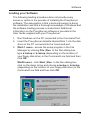
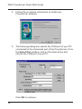
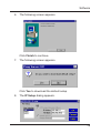
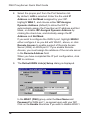
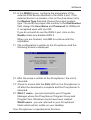
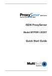
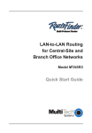
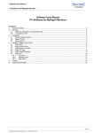
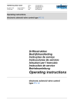
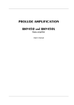
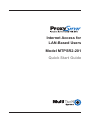
Internet Access for
LAN-Based Users
Model MTPSR2-201
Quick Start Guide
Quick Start Guide
82078800 Revision A
DSU ProxyServer (Model No MTPSR2-201)
This publication may not be reproduced, in whole or in part,
without prior expressed written permission from Multi-Tech
Systems, Inc. All rights reserved.
Copyright © 1998, by Multi-Tech Systems, Inc.
Multi-Tech Systems, Inc. makes no representations or warranties
with respect to the contents hereof and specifically disclaims any
implied warranties of merchantability or fitness for any particular
purpose. Furthermore, Multi-Tech Systems, Inc. reserves the right
to revise this publication and to make changes from time to time in
the content hereof without obligation of Multi-Tech Systems, Inc. to
notify any person or organization of such revisions or changes.
Record of Revisions
Revision
A
(8/1/98)
Description
Manual released. All pages at revision A.
Patents
This Product is covered by one or more of the following U.S.
Patent Numbers: 5.301.274; 5.309.562; 5.355.365; 5.355.653;
5.452.289; 5.453.986. Other Patents Pending.
TRADEMARK
Trademark of Multi-Tech Systems, Inc. is the Multi-Tech logo.
Windows is a registered trademark of Microsoft.
Multi-Tech Systems, Inc.
2205 Woodale Drive
Mounds View, Minnesota 55112
(612) 785-3500 or (800) 328-9717
Fax 612-785-9874
Tech Support (800) 972-2439
Internet Address: http://www.multitech.com
Fax-Back (612) 717-5888
Contents
Introduction ................................................................................... 4
Related Documentation ................................................................. 5
Safety Warnings ............................................................................ 6
Unpacking your ProxyServer ........................................................ 6
V.35 Shunt Procedure ................................................................... 7
Cabling your ProxyServer ............................................................. 9
Cabling Procedure ...................................................................... 10
Loading your Software ................................................................. 11
Limited Warranty ......................................................................... 16
Service .................................................................................. 17
iii
DSU ProxyServer Quick Start Guide
Introduction
Welcome to Multi-Tech's new DSU ProxyServer, model
number MTPSR2-201, a single, secure gateway that provides
multiple LAN users with high performance Internet access
over a leased line. The DSU ProxyServer functions as a TCP/
IP proxy server that resides on the outer edge of your firewall
and provides up to 56K of bandwidth to LAN users. The DSU
ProxyServer features a 10BaseT port for local LAN
connection, a command port for configuration, a 56K bps DDS
4-wire WAN connection, and a RS232 port for auto-dial
backup in case the leased line connection is lost. System
management is provided through the command port using
bundled Windows® software which provides easy-to-use
configuration menus.
The MTPSR2-201 also supports dial-in Remote Access Server
(RAS) when the WAN 2 port is configured to support it. Refer
to the Software Installation section of this guide, and to your
ProxyServer User Guide for more details on RAS.
RD
TD
CL
LK
RD
TD
CD
NS
DS
RD
TD
CD V35
Figure 1. DSU ProxyServer
4
Introduction
Related Documentation
The DSU ProxyServer Quick Start Guide is intended to be
used by qualified systems administrators and network
managers. This quick start provides the necessary information
for a qualified person to unpack, cable, load software, and
configure the unit for proper opearation.
A detailed DSU ProxyServer User Guide is also provided with
your unit. This user guide provides in-depth information on the
features and functionality of Multi-Tech’s ProxyServer. The
User Guide is provided in diskette form and is also available
from our web site.
The diskette media is produced using Adobe Acrobat for
viewing and printing the user guide. To view or print your copy
of a user guide, load Adobe Acrobat Reader on your system.
Adobe Acrobat Reader can be downloaded from Adobe’s web
Site at:
http://www.adobe.com/prodindex/acrobat/roadstep.html
Launch the Reader and select the .pdf file from the diskette.
Viewing and printing a user guide from the web also requires
that you have the Adobe Acrobat Reader loaded on your
system. The DSU ProxyServer User Guide is also available on
Multi-Tech’s WEB site at:
http://www.multitech.com
From the MTS homepage, click Support | Manuals |
ProxyServer and choose DSU ProxyServer to download the
.pdf file.
5
DSU ProxyServer Quick Start Guide
Safety Warnings
1. Never install telephone wiring during a lightning storm.
2. Never install telephone jacks in wet locations unless
the jack is specifically designed for wet locations.
3. Never touch uninsulated telephone wires or terminals
unless the telephone line has been disconnected at the
network interface.
4. Use caution when installing or modifying telephone lines.
5. Avoid using a telephone (other than a cordless type)
during an electrical storm. There may be a remote risk of
electrical shock from lightning.
6. Do not use the telephone to report a gas leak in the vicinity
of the leak.
Unpacking your ProxyServer
Remove all items from the box.
Quick Start Guide
RD
TD
CL
LK
RD
TD
CD
NS
DS
RD
TD
CD
V35
Figure 2. Unpacking
6
V.35 Shunt Procedure
V.35 Shunt Procedure
If you are using an external DCE device on the WAN 2 RS232/
V.35 port, and the connection will be a V.35 connection, the the
interal shunt must be moved from the RS232C (default)
position prior to cabling and power-up. The following steps
detail the procedures for switching the shunt.
Step
Procedure
1
Ensure that the external power supply is disconnected
from the ProxyServer.
2
Turn the ProxyServer over and remove the cabinet
mounting screw from the chassis.
Front Panel
Back Panel
Cabinet Mounting Screw
Figure 2-2. Cabinet Mounting Screw
3
Being sure to support the back panel, turn the
ProxyServer right-side-up, tilt the back panel down, and
slide the circuit board out of the chassis.
7
DSU ProxyServer Quick Start Guide
4
Place the unit on a flat, grounded surface, with the LED’s
facing you.
5
Pry the shunt out of the RS232 position, and insert it in the
V.35 position.
8-Position DIP Switch
LEDs
5
6
7
8
RAM Sockets
Back Panel Connectors
V.35 Shunt Position
RS232C Shunt Position
Figure 2-3. Shunt Positions
8
6
Align the board with the guide slots on the inside of the
chassis and carefully slide the board back into the chassis.
7
Being sure to support the back panel, turn the
ProxyServer over again, and replace the cabinet mounting
screw.
8
Turn the ProxyServer right-side-up again and proceed to
the nect section to connect the cables.
Cabling
Cabling your ProxyServer
Cabling your ProxyServer involves making the proper Power,
Command Port, and DSU connections, and optionally, the
RS232/V.35 connection. Figure 3 shows the back panel
connectors and the associated cable connections. The table
that follows details the procedures for connecting the cables to
your ProxyServer.
RS232/V.35
56K DSU
10BASET
COMMAND
POWER
ON
OFF
Power Connection
DCE Connection
DDS WAN Connection
PC Connection
Ethernet Connection
Figure 3. Cable Connections
9
DSU ProxyServer Quick Start Guide
Cabling Procedure
Step
Procedure
1. Connect one end of the power supply to a live AC outlet
and connect the other end to the ProxyServer as shown in
Figure 3. The power connector is a 6-pin circular DIN
connector.
2. Connect the ProxyServer to a PC by using the short RJ45
to DB25 (female) cable provided with your unit. Plug the
RJ45 end of the cable into the Command port of the
ProxyServer and the other end into the RS232 cable from
the PC serial port. See Figure 3.
3. Connect a network cable to the ETHERNET 10BASET
connector on the back of the ProxyServer. Connect the
other end of the cable to your network.
4. Connect one end of the RJ48 cable to the 56K DSU
connector on the back of the ProxyServer. Connect the
other end to your DDS WAN connection.
5. If you wish to use the optional RS232 port for dial back-up,
connect one end of an RS232 cable to the RS232/V.35
connector on the back of the ProxyServer and connect the
other end of the cable to an external DCE device such as
a modem or T1 CSU.
5. Turn on power to the ProxyServer by placing the ON/OFF
switch on the back panel to the ON position. Wait for the
FAIL LED on the ProxyServer to go OFF before
proceeding. This may take a couple of minutes to go OFF.
At this time your ProxyServer is completely cabled. Proceed
to the next section to load the ProxyServer software.
10
Software
Loading your Software
The following loading procedure does not provide every
screen or option in the process of installing the ProxyServer
software. The assumption is that a technical person is doing
the installation and that a thorough knowledge of Windows and
the software loading process is understood. Additional
information on the ProxyServer software is provided in the
User Guide supplied with your ProxyServer.
1. Run Windows on the PC connected to the Command Port.
2. Insert the ProxyServer diskette labeled Disk 1 into the disk
drive on the PC connected to the Command port.
3. Win3.1 users - access the setup program in the File
Manager by clicking File | Run. In the Run dialog box,
type a:\setup or b:\setup (depending on the location of
your floppy disk drive) in the Command Line field and then
click OK.
Win95 users - click Start | Run. In the Run dialog box
click on the down arrow and choose a:\setup or b:\setup
(depending on the location of your floppy disk drive) in the
Command Line field and then click OK.
11
DSU ProxyServer Quick Start Guide
4. Follow the on-screen instructions to install your
ProxyServer software.
5. The following dialog box selects the COM port of your PC
conntected to the Command port of the ProxyServer. From
the Select Port window, click on the down arrow and
choose the COM port of your PC.
Click OK to continue.
12
Software
6. The following screen appears.
Click Finish to continue.
7. The following screen appears.
Click Yes to download the default setup.
8. The IP Setup dialog appears.
13
DSU ProxyServer Quick Start Guide
8. Select the proper port from the Port Selection list.
By default, LAN is selected. Enter the the valid IP
Address and Net Mask assigned by your ISP.
Highlight WAN 1, and choose either ISP Assigns
Dynamic Address (default) to allow the ISP to
automatically assign the ProxyServer IP address and Net
Mask, or disable ISP Assigns Dynamic Address by
clicking the check box, and statically assign the IP
Address and Net Mask.
If you wish to configure the WAN 2 port, highlight WAN 2
either configure it as you did with WAN 1, above, or click
Remote Access to enable support of Remote Access
Server (RAS) on WAN port 2. If you enable Remote
Access, you must assign the address of the remote server
in the Remote Address field.
When you have completed the IP port configuration, click
OK to continue.
9. The Default WAN Link(s) Setup dialog is displayed.
In the WAN 1 (DSU) group, enter the User Name and
Password for WAN port 1, as agreed upon with your ISP.
Click on the Enable check box if you wish to disable WAN 1.
14
Software
10. In the WAN 2 group, configure the parameters of the
external DCE device attached to the WAN 2 port. If the
external device is a modem, click on the drop down list in
the Modem Type field and choose the proper modem
type. The enter the proper dial number in the Dial Number
field. Assign the User Name and Password for WAN port
2, as agreed upon with you ISP.
If you do not wish to use the WAN 2 port, click on the
Enable check box disable WAN 2.
When you are finished, click OK to continue with the
installation.
11. The configuration is written to the ProxyServer and the
following screen is displayed.
12. After the setup is written to the ProxyServer, the unit is
rebooted.
13. Check to ensure that the FAIL LED on the ProxyServer is
off after the download is complete and the ProxyServer is
rebooted.
27. Win3.1 users - you are returned to your Program
Manager where the ProxyServer Program Group and
Program Item (Windows icons) have been created.
Win95 users - you are returned to your ProxyServer
folder which will be visible on your desktop.
Your ProxyServer is operational at this time.
15
DSU ProxyServer Quick Start Guide
Limited Warranty
Multi-Tech Systems, Inc. (“MTS”) warrants that its products will be
free from defects in material or workmanship for a period of two
years from the date of purchase, or if proof of purchase is not
provided, two years from date of shipment. MTS MAKES NO
OTHER WARRANTY, EXPRESSED OR IMPLIED, AND ALL
IMPLIED WARRANTIES OF MERCHANTABILITY AND FITNESS
FOR A PARTICULAR PURPOSE ARE HEREBY DISCLAIMED.
This warranty does not apply to any products which have been
damaged by lightning storms, water, or power surges or which
have been neglected, altered, abused, used for a purpose other
than the one for which they were manufactured, repaired by the
customer or any party without MTS’s written authorization, or used
in any manner inconsistent with MTS’s instructions.
MTS’s entire obligation under this warranty shall be limited (at
MTS’s option) to repair or replacement of any products which
prove to be defective within the warranty period, or, at MTS’s
option, issuance of a refund of the purchase price. Defective
products must be returned by Customer to MTS’s factory
transportation prepaid.
MTS WILL NOT BE LIABLE FOR CONSEQUENTIAL DAMAGES
AND UNDER NO CIRCUMSTANCES WILL ITS LIABILITY
EXCEED THE PURCHASE PRICE FOR DEFECTIVE
PRODUCTS.
16
Warranty, Service and Regulatory Information
Service
Multi-Tech has an excellent staff of technical support personnel
available to help you get the most out of your Multi-Tech product.
Refer to your ProxyServer User Guide for Warranty and Service
information.
FCC Declaration
NOTE: This equipment has been tested and found to comply with
the limits for a Class A digital device, pursuant to Part 15 of the
FCC Rules. These limits are designed to provide reasonable
protection against harmful interference when the equipment is
operated in a commercial environment. This equipment generates,
uses and can radiate radio frequency energy, and if not installed
and used in accordance with the instructions, may cause harmful
interference to radio communications. Operation of this equipment
in a residential area is likely to cause harmful interference in which
case the user will be required to correct the interference at his own
expense.
Warning: Changes or modifications to this unit not expressly
approved by the party responsible for compliance could void the
user’s authority to operate the equipment.
17
82085000