1
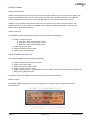
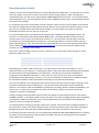
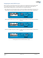
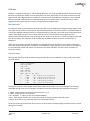
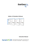
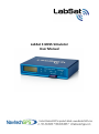
LabSat 3 GNSS Simulator User Manual This page intentionally left blank Page | 2 Revision 1.4 15 January 2015 Contents Introduction........................................................................................................................................... 4 How does it work? ..................................................................................................................... 4 Components .......................................................................................................................................... 5 LabSat 3 Front ............................................................................................................................ 5 LabSat 3 Rear ............................................................................................................................. 5 LabSat 3 media ...................................................................................................................................... 6 LabSat 3 file formats .................................................................................................................. 6 LabSat 3 SD Card ........................................................................................................................ 6 LabSat 3 500GB Hard Disk Drive.................................................................................................. 6 LabSat 3 Label ............................................................................................................................ 6 Quick start guide .................................................................................................................................... 7 Menu Layout.......................................................................................................................................... 8 Replay operation in detail ...................................................................................................................... 9 Record operation in detail .................................................................................................................... 10 Navigating the LabSat HDD file layout................................................................................................... 11 Battery operation and charging ............................................................................................................ 12 Battery fitting, removal and handling ................................................................................................... 13 External reference clock input .............................................................................................................. 14 Digital channels.................................................................................................................................... 14 Expansion connector ............................................................................................................................ 15 CAN Bus ............................................................................................................................................... 16 DIGITIZE mode ......................................................................................................................... 16 LOG FILE mode ......................................................................................................................... 16 Filtering CAN frames ................................................................................................................ 17 Digital in/out ....................................................................................................................................... 18 Remote control .................................................................................................................................... 18 LabSat device registration .................................................................................................................... 18 Ordering information ........................................................................................................................... 19 Optional accessories ................................................................................................................ 19 Converting LabSat scenarios ................................................................................................................. 20 Recommended media .......................................................................................................................... 21 Upgrading LabSat 3 firmware ............................................................................................................... 21 How to upgrade the firmware .................................................................................................. 21 SatGen software .................................................................................................................................. 22 Why use SatGen software? ....................................................................................................... 22 Troubleshooting guide ......................................................................................................................... 23 LabSat 3 specifications ......................................................................................................................... 24 Connector pin data............................................................................................................................... 25 Expansion port 36 way MDR type connector ......................................................................................... 25 LabSat 3 dimensions............................................................................................................................. 26 Contact information ............................................................................................................................. 27 Page | 3 Revision 1.4 15 January 2015 Introduction LabSat 3 is a lightweight, portable record and replay system for GNSS testing. With the ability to record real world GNSS signals directly to SD card or HDD storage, the LabSat 3 is a simple to use, fully stand-alone system. Recorded signals can be replayed back by LabSat 3 in the Lab enabling development and testing of most types of GNSS equipment. Alternatively SatGen software can also be used to create simulated GNSS signals from map or user defined trajectory. Despite its simplicity, the LabSat 3 product range supports a number of powerful features for use in industries such as automotive, sports and aerospace including dual RF channels for multiple constellation testing, dual CAN Bus recording, inertial sensor logging and battery powered operation. Additional features:→ → → → → → → → → → → Available for GPS, GLONASS, Galileo, BeiDou, QZSS Simple to use one touch recording Record or replay using external USB hard drive RS232, Digital & Dual CAN interface Remote control over Ethernet External 10MHz Reference input OCXO option OEM version available for system integrators Digital input for event marking or 1PPS recording Adjustable attenuation (0 – 31dBm) On-board GNSS receiver for monitoring RF during record and replay The LabSat 3 line-up includes a number of variants to suit a range of testing requirements. These are: Version RLLS03-3RP RLLS03-3P RLLS03-2RP RLLS03-2P RLLS03-1RP RLLS03-1P Description Triple RF channel record & replay system with CAN Bus / RS232 / Digital IO Triple channel replay only system with CAN Bus / RS232 / Digital IO Dual RF channel record & replay system with CAN Bus / RS232 / Digital IO Dual channel replay only system with CAN Bus / RS232 / Digital IO Single RF channel record & replay system Single RF channel replay only system How does it work? GNSS stands for Global Navigation Satellite Systems and is a general term that covers satellite positioning constellations belonging to different countries around the world. These include, among others, the United States ‘GPS’, the Russian ‘GLONASS’ and the Chinese ‘BeiDou’ systems. LabSat 3 is capable of recording and then replaying the raw radio signals that are transmitted by the various constellations of satellites. LabSat 3 receives the signal from an antenna just like a standard GNSS receiver but instead of processing each of the received signals to calculate a position fix, LabSat 3 samples and stores the antenna signal at very high speed. When the stored antenna signal is replayed by LabSat 3 into a standard GNSS receiver such as a portable navigation system, the receiver will see essentially, the same signal that it would see if it were connected to an antenna including movement, delays and multipath effects. This makes LabSat 3 invaluable for recording moving scenarios such as driving through a city in a car. One of the benefits of using a recorded test signal is consistency. For example, if testing of a product involves going for a drive each time the firmware is updated, the satellite positions and atmospheric conditions will be different for every drive. If the drive is recorded once with LabSat 3, the recorded signal can be replayed over and over on the bench saving hours of drive time and with the knowledge that the conditions will be the same for each replay. Page | 4 Revision 1.4 15 January 2015 Components LabSat 3 has been designed to be portable and simple to use allowing virtually anyone to gather field test signals without in depth training. Recording GNSS signals is as simple as positioning the antenna and pressing one button. The sunlight-readable graphic display gives instant feedback of record status and can show live histogram data to verify satellites in view during recording. Back at the Lab, recorded signals can be replayed at the push of a button for repeatable, reliable testing. LabSat 3 Front Display Keypad SD Card Slot Media LED Indicator LabSat 3 Rear Name POWER HOST USB ETHERNET USB RF OUT RF IN REF Expansion Type 2 pin LEMO USB ‘A’ RJ45 USB ‘B’ SMA SMA SMA 36 Way MDR Description 8 to 30 VDC Power Supply input Connection of USB Storage devices Remote access and control NMEA data output Output RF signal Input RF signal (RP variants only) 10MHz Reference Clock Input 1PPS, Digital I/O*, CAN*, RS232* *Model dependent – available as options. Page | 5 Revision 1.4 15 January 2015 LabSat 3 media LabSat 3 file formats LabSat 3 uses I&Q binary data and runs the FAT32 file format. LabSat 3 files are recorded into a folder with separate 2GB data files which will run sequentially when replayed. The folder description GPS_000 will contain several files with the name format GPS_000_000.ls3. These will automatically increment. LabSat 2 (.ls2) and LabSat (.bin) files will need to be converted to this format to play on LabSat 3. The LabSat Scenario Converter Software is supplied on the LabSat 3 Hard Disk Drive (HDD). Please see the section ‘Converting LabSat Scenarios’. LabSat 3 SD Card The 32GB SD card included with the LabSat 3 system includes the following files: → LabSat 3 sample scenarios → GPS_000 - Static 5 minute GPS scenario → GLO_001 - Static 5 minute GLO scenario → BDS_001 - Static 5 minute BDS scenario → LabSat 3 quick start video → SatGen simulation software video → LabSat 3 quick start guide PDF LabSat 3 500GB Hard Disk Drive The LabSat 3 500GB hard disk includes the following: → → → → → LabSat 3 scenario library description PDF LabSat 3 quick start video SatGen simulation software video LabSat scenario converter utility LabSat 3 scenario library – a worldwide selection of LabSat 3 scenario files with supporting KML and Google Earth jpeg picture files. The LabSat 3 HDD uses USB3.0 for fast data transfer and is formatted to FAT32. LabSat 3 Label The LabSat 3 label is located on the left side toward the rear. Please quote your serial number in all correspondence. Page | 6 Revision 1.4 15 January 2015 Quick start guide In addition to this guide, a short LabSat 3 Quick Start video is available on the LabSat 3 SD card and also on the LabSat 3 HDD. Example of Replay - using the included SD card with preloaded scenario. Briefly press the power button to power up the LabSat 3. Connect from the RF output on the rear of the LabSat 3 to your GPS system antenna input. With the SD card inserted, use the UP/DOWN arrows to select a file. Press the PLAY button to start replay. LabSat 3 contains an on board GNSS receiver that allows monitoring of the RF signals during record or replay. To show a live histogram of satellite signal levels detected by the on board receiver, press the OK button during replay. Press the OK button again to return to the replay status display. During replay, pressing the PLAY button will halt replay and return to the file list. Example of Record – Recording your own file to an SD card (RP variants only) To record a new file, connect the LabSat 3 antenna to the RF input on the rear of the LabSat. Ensure that the antenna has a clear view of the sky, press the REC button to start recording. Press the REC button again to stop recording. While recording, if the SD card becomes full, recording will stop automatically. During recording, pressing the OK button will switch the display to show a live histogram view of the satellite levels being received by the on-board GNSS monitor. Pressing the OK button again will return to the record status display. During recording, while using battery power, the GNSS monitor display will automatically revert to the record display after a short period to conserve battery power. This power save feature can be switched off but it is recommended to be left active for maximum battery life. Page | 7 Revision 1.4 15 January 2015 Menu Layout File → Info - Display file info for selected file. → Delete – Delete selected file Yes/No. → Format SD/USB – Erase and Format SD/USB Yes/No. Constellation → → → → GPS/GAL – Tick to select GPS/Galileo constellation for recording. GLONASS – Tick to select GLONASS constellation for recording. BeiDou – Tick to select BeiDou constellation for recording. 2Bit – Record with 2bit quantisation when single constellation is selected. → → → → Loop – selected file will replay continuously. Pause Time – Defines the pause time between each replay. From – Specify a time in the scenario to replay from. For - Specify how long the scenario will replay for. Play Record → For - Specify how long the LabSat 3 will record for. Setup → → → → Display – Adjust display contrast and backlight brightness. RF Test – Outputs RF test signal. Power Save – When selected, will power down display backlight and internal monitor during recording. CLK REF → Internal - As the default setting LabSat 3 will use it internal reference clock. → External 10MHz – Allows the user to connect a 10MHz reference signal on the REF input. → Time – Configure internal clock using UTC time from internal GNSS monitor or set manually. → LAN → DHCP – Enable/Disable DHCP. → IP Address – Set the IP address assigned to LabSat 3. → SUBNET MASK - Set the Subnet mask assigned to LabSat 3. → DEFAULT GATEWAY - Set the default gateway for the network. → Digital → CH1 → 1PPS – Record 1PPS signal from internal GNSS monitor (disable power save). → RS232 – Record RS232 signal. → CAN CH1 – Record CAN Bus channel 1. → DIGI – Record state of DIGI input signal. → CH2 → 1PPS – Record 1PPS signal from internal GNSS monitor (disable power save). → RS232 – Record RS232 signal. → CAN CH2 – Record CAN Bus channel 2. → DIGI – Record state of DIGI input signal. CAN → Record Type → Digitize – When selected the CAN data will be digitized and integrated into the .LS3 file. → Log File – When selected the CAN data will be logged into a separate .txt file. → CH1 → Baud rate – Enables the user the set the desired baud rate. → Silent Record - Determines whether or not the LabSat sends an acknowledge pulse during recording. → CH2 → Baud rate – Enables the user the set the desired baud rate. → Silent Record – Determines whether or not the LabSat sends an acknowledge pulse during recording. About – Contains information specific to the LabSat e.g. serial number & firmware version. Exit – Return to file list. Page | 8 Revision 1.4 15 January 2015 Replay operation in detail LabSat 3 uses SD card or HDD memory for storage and playback of GNSS data. It is important to note that Class 10 or higher cards must be used to sustain the transfer speeds required. Racelogic recommend SanDisk Extreme Class 10 cards for best performance. The 500GB USB Hard Disk Drive (HDD) supplied contains a selection of pre-recorded scenarios from around the world. These scenarios can easily be copied to the SD card for replay. The HDD supports either USB2.0 or USB3.0. For optimum data transfer performance using a PC that supports USB3.0 for file transfer from HDD to SD card is recommended. The RF OUT connector is a 50Ω output which can be connected directly to the antenna input of the GNSS receiver being tested. The RF OUT connector of LabSat 3 is DC blocked internally so almost any device can be connected to this port. When a file is selected for replay, the LabSat will configure constellation frequencies and digital channels automatically before starting replay. If a triple constellation file is selected for replay on a single channel LabSat, all three constellations will be displayed before replay allowing the user to select one. During replay, pressing OK will show a live histogram of satellite levels detected by the internal GNSS receiver. The internal receiver currently only supports GPS and GLONASS constellations. This has no effect on the ability of LabSat 3 to record or replay BeiDou signals. When displayed, the UP/DOWN keys switch between GPS and GLONASS monitor modes. Please note that when switching between GPS and GLONASS display modes, the internal receiver will take some time to re-acquire satellite signal levels. In the case of GLONASS signals, it may take over a minute to show the satellite signal information. LabSat 3 comes with an internal 31dB attenuation capability. To increase the attenuation press the up arrow, this will increase the attenuation by 1dB. The down arrow will decrease the attenuation level. Attenuation Display Attenuation Controls Page | 9 Revision 1.4 15 January 2015 Record operation in detail LabSat 3 uses SD card and HDD memory for storage and playback of GNSS data. It is important to note that Class 10 or higher cards must be used to sustain the transfer speeds required. When recording two constellation types, the data rate is approximately 8.2MB (Mega Bytes) per second. To ensure that data is collected without error, the card should be able to sustain 10MB per second. Spare cards and HDDs may be purchased from Racelogic. It is important that cards are formatted as FAT32. LabSat 3 is able to format cards and HDDs in FAT32 with the optimum configuration for high speed recording. When a card or HDD is formatted by LabSat 3, it will also carry out a performance test to determine whether or not the media can sustain the required bandwidth and inform the user if this is not the case. For record capable systems, the LabSat will be supplied with a magnetic mounting GNSS antenna. The antenna is an active device with approximately 28dB of gain. The LabSat provides a 2.85V DC bias for antenna power on the centre pin of the RF IN connector. It is also possible to use third party antennas providing they are compatible with the 2.85V bias. If connecting LabSat to an antenna which requires a higher bias voltage (e.g. 12v), the antenna bias must be supplied by the user and an appropriate DC block (such as DCB from http://gpsnetworking.com/attenuators.asp) must be inserted at the LabSat 3 RF IN connector to avoid damage to the LabSat. There are a number of GNSS systems currently in operation or in a test phase. These operate on 3 main frequency bands. These are:Frequency Band Constellations 1575.42MHz 1602MHz 1561.098 GPS L1, Galileo E1, QZSS, SBAS GLONASS L1 BeiDou B1 Depending on the model, LabSat 3 will have 1, 2 or 3 RF channels. This allows recording of 1, 2 or 3 frequency bands so, for example, a 2 constellation LabSat 3 may record the band containing GPS L1/Galileo E1 and the band containing GLONASS L1 simultaneously. Recording of the desired constellations is configured in the CONSTELLATION menu. In this menu, the user can tick up to three of the desired constellation groups (depending on version). If only one constellation is ticked, then an additional option for 2bit will be available to allow 2bit quantized recording for the selected constellation. Once the constellations are configured, exit the menu and press the REC button to begin recording. A new file will be created each time recording starts. The file name used corresponds to the constellations selected. For example, if GPS and GLONASS are selected for recording, the file created will be GPSGLO_nnn where nnn is a number that increments with each new recording. Details of the LS3 file format are available on request from Racelogic. During recording, pressing the OK button will switch the display to show satellite levels for either GPS or GLONASS satellites. In this display mode, the up and down arrow keys will toggle between GPS or GLONASS constellations. BeiDou constellation is not currently supported by the internal monitor but BeiDou B1 signals can still be recorded and replayed. To maximize battery life during recording, LabSat 3 has a power save mode which is enabled by default I n the setup menu. Power save mode recognizes when running from battery power and will dim the display backlight and power-down the internal GPS/GLONASS monitor after 30 seconds of user inactivity. If recording from passive antennas such as the Maxtenna M1516HCT-SMA GPS/GLONASS antenna, enabling the power-save mode will also provide the highest possible sensitivity by ensuring that unused modules within LabSat 3 are switched off. Page | 10 2015 Revision 1.4 15 January Navigating the LabSat HDD file layout Below is a guide to how the folder layout works on LabSat 3. This example below shows the folder layout on the HDD provided with LabSat 3. The LabSat USB HDD is uses multiple folders. When folders are detected LabSat will display them in a similar fashion to a PC using the DIR indicator. When USB media is connected LabSat 3 will scan for files and display the files/folders containing the .ls3 format. When recording to USB HDD LabSat will save scenario files to the first folder in the directory. <DIR> indicates a folder and not a scenario. Pressing ‘OK’ will navigate to the next stage of the scenario directory. Continue to navigate using ‘OK’ until <DIR> is no longer shown, this indicates the file is a scenario not a directory. Pressing play will start the individual scenario replay. Page | 11 2015 Revision 1.4 15 January Battery operation and charging LabSat 3 variants that include internal battery use replaceable Varta Li-Polymer battery packs. These packs are fully certified (UL, CE, UN38.3 Transport). Each pack gives around 2 hours of record time. When the LabSat 3 is powered externally, it will charge the internal battery pack if fitted and seamlessly switch over to battery operation when external power is removed. Alternatively, an external battery charger is available to order. To remove the battery from LabSat 3, unscrew the battery plate on the rear of the device and slide the battery out. When operating from battery power, the battery charge status will be shown in the top-right section of the display . If external power is connected and the battery is being charged, a power symbol will be shown over the battery symbol. The discharge temperature range for the battery is -20°C to +60°C. Therefore, if the LabSat is operating from battery power, it will power-down if the temperature falls outside this range. The charge temperature range of the battery pack is 0°C to +45°C. Outside this temperature range, the LabSat will switch off charging of the internal battery but will continue to operate from the external power supply. Warning - Li-Polymer Battery Pack - Risk of fire or explosion. Do not incinerate, disassemble, short terminals, expose to temperature above 140°F/60°C. Do not charge battery unattended, expose of batteries in fire or disassemble the batteries. Page | 12 2015 Revision 1.4 15 January Battery fitting, removal and handling → Replace battery with Racelogic, Part No. RLACS201 only. Use of another battery may present a risk of fire, explosion or other malfunction. → Caution: The battery used in this device may present a fire or chemical burn hazard if mistreated. Do not disassemble or heat above 100°C (212°F) or incinerate. → To remove or change the battery disconnect from mains power. Remove the holding plate market “Battery” on the rear of the unit. Slide out the old battery and replace ensuring that the connectors on the replacement battery align with the connectors inside. Please dispose of old or used batteries promptly. Keep away from children. → The battery should be fully charged when stored. If a battery is left depleted for a prolonged period then it is likely that the performance of the battery will degrade and may be unusable. → Never incinerate nor dispose of cells in a fire. → Never short circuit the battery pack. It will generate very high currents resulting in overheating of the cells, which may cause electrolyte leakage, gassing or fire. → Never disassemble the cells. Disassembling cells may cause an internal short circuit in the cell, which could further result in gassing, fire, or other problems. → If for any reason the battery pack becomes damaged it is possible that it may leak electrolyte. The electrolyte is harmful to the human body. If the electrolyte comes into contact with the skin, eyes or others parts of body, the electrolyte shall be flushed immediately with fresh water. Seek immediate medical advice from a physician. → Cells may be damaged during shipping by shocks, or other causes. If any abnormal features of the cells are found such as: damage to a plastic envelope of the cell, deformation of the cell container, smell of electrolyte, an electrolyte leakage, or other abnormalities, the cells should not be used. Cells with a smell of electrolyte or leakage should be kept away from fire to avoid ignition. Page | 13 2015 Revision 1.4 15 January External reference clock input LabSat 3 features an external reference input for synchronization to a 10MHz clock. To use this feature, connect a 10MHz reference signal with minimum +6dB level to the REF IN SMA connector and ensure that the External 10MHz reference clock option is ticked in MENU SETUP CLK REF External 10MHz. When the external reference input is enabled, the symbol will appear in the top right corner of the LCD. Digital channels There are 1 or 2 channels available for external digital data capture depending on the system variant and the options that have been purchased with the LabSat. Recorded digital channel data is synchronized to each sample of recorded RF data; the maximum input frequency for each channel is 1MHz. To record 2 digital channels, at least 2 RF channels must be selected or 1 single channel with 2-bit quantisation. The Digital menu allows CH1 or CH2 (subject to LabSat variant) to be configured to record any of the following parameters:- Function 1PPS Description This is the 1 Pulse Per Second output from the internal GNSS monitor and will become active once the internal GNSS monitor has a position fix. Note, that if using battery power with the power save option enabled, the GNSS monitor will power-down after approx 30 seconds into the recording and therefore not be present in the recorded data. During replay, the recorded 1PPS signal will be output on pin 2 (DIGO) of the expansion connector. Option or Standard CAN CAN 1 and CAN 2 on the expansion connector (RLACS202) will be recorded on channel 1 & 2 of the LabSat 3. See section CAN BUS for more details. Option on Single constellation variant* RS232 This will record an RS232 level signal input on pin 18 of the expansion connector. During replay, pin 17 of the expansion connector will output the recorded data at RS232 level. Because the RS232 signal is digitized directly, it is not necessary to configure baud rate. Option on Single constellation variant* DIGI Will record the digital state of pin 3 of the expansion connector. During replay, the signal will be re-created on pin 2 (DIGO) of the expansion connector. See section EXPANSION CONNECTOR for more details. Option on Single constellation variant* Standard *Contact Racelogic or your LabSat distributor to purchase upgrade options Page | 14 2015 Revision 1.4 15 January Expansion connector The EXPANSION connector on the rear of LabSat 3 gives access to a number of signals including CAN Bus, RS232, 1PPS & Digital input/output. Accessory RLACS202 is used to provide user signal access for integration into the users test system. Pin functions are as follows:Number Name 1 1PPS 2 3 4 5 6 7 8 9 10 11 12 13 14 15 16 17 DIGO DIGI CAN 1 H CAN 1 L CAN 2 H CAN 2 L I2C SDA I2C SCL I2C VCC RS232 Tx I/O O O I 18 RS232 Rx I 19 20 21 22 23 24 25 26 27 28 29 30 31 32 33 34 35 36 O O O CAN Bus High Channel 1 – Standard ISO11898 voltage signal levels for CAN CAN Bus Low Channel 1 – Standard ISO11898 voltage signal levels for CAN CAN Bus High Channel 2 – Standard ISO11898 voltage signal levels for CAN CAN Bus Low Channel 2 – Standard ISO11898 voltage signal levels for CAN I2C Bus Data – Reserved for future use I2C Bus Clock – Reserved for future use I2C Bus voltage level – Reserved for future use RS232 data output. NMEA Data from GNSS monitor or User RS232 data if enabled. Standard RS232 Level. User RS232 data which is recorded if RS232 is enabled in Digital configuration menu. Standard RS232 Level. Ground Connection Ground Connection Ground Connection I/O I/O I/O I/O Reserved Reserved Reserved Reserved O O O O Ground Connection Ground Connection Connected to input power – Max 250mA Connected to input power – Max 250mA Page | 15 2015 Ground Ground Ground IO_0 IO_1 IO_2 IO_3 Ground Ground Power Power I/O I/O I/O I/O I/O I/O I/O O Function Signal from Internal GNSS monitor. Becomes active when monitor is locked. 5V Level. 25mA User digital output. 5V Level. 25mA max User digital input. Up to 12 V input level. Detection threshold=2.5V Revision 1.4 15 January CAN Bus LabSat 3 is capable of listening to, and recording data from, two separate CAN networks. Dual channel CAN Bus data recording with LabSat 3 can be achieved in two ways. Depending on the mode selected, the CAN signal will be either digitized and re-created on a raw bit level or decoded and recorded in a time-stamped text file. The CAN mode operation is selected under the menu option ‘CAN’ in the SETUP section. When ‘digitized’ mode is selected, the channel is configured in the ‘Digital’ menu. DIGITIZE mode The ‘Digitize’ mode records CAN data by listening to the bus and sampling the rising and falling edges of the raw signal. Timing codes are inserted into the recorded GPS data so that when the file is replayed LabSat recreates the digitized CAN signal exactly as it appeared during recording. This mode can therefore be used to capture data along with bus-errors or data-collisions and is synchronised to the RF signal to within approximately 60 nanoseconds. One advantage of this mode is that there is no-need to configure CAN baud rate. During replay, the CAN data can be viewed with a CAN Bus analyser tool such as Vehicle-SPY or CANAlyzer. When using the digitize method the CAN data is replayed exactly as recorded, there will be no arbitration with other systems during replay. Therefore, if the CAN data is replayed into a system which is transmitting its own CAN data, LabSat will ‘speak’ over the top of the other CAN data. This may cause corruption of some data frames. LOG FILE mode Selecting the ‘LOG FILE’ mode of CAN recording enables data to be recorded in an easy to read text log file as shown below. Labsat3 SN:00323502 DATE:12/06/2014 TIME:13:07 CAN1: 500.00K CAN2: 500.00K GNSS: GPS, GLO CHAN, TIME, ID, DLC, DATA 2 0.060 360 8 0B 1 0.060 420 8 7B 2 0.062 620 8 0D 1 0.063 428 7 00 2 0.064 200 7 01 70 46 24 8E F5 C8 02 02 00 01 35 84 1B 00 E2 44 01 81 37 02 60 00 7E 00 00 80 A3 3E 1D 37 02 20 00 The log file contains a short header detailing the LabSat serial number, time, date CAN Bus baud settings and GNSS settings. Each line of CAN data recorded contains the following space-delimited information:1. CHAN - CAN Channel that the data was received on 1 or 2. 2. TIME - Timestamp to 1ms resolution. 3. ID - Identifier, ‘x’ suffix is shown for extended CAN IDs. 4. DLC - Data length code DLC, this shows the number of data bytes within the CAN frame. 5. DATA - Data section, up to 8 bytes of data as indicated by the DLC. At the end of the log file there will be a summary of the number of CAN messages received on each channel during the recording. Page | 16 2015 Revision 1.4 15 January The log file is recorded in the same folder as the RF data and has a .TXT file extension. During recording, the CAN controller listens to the CAN bus and stores incoming data. LabSat 3 will transmit acknowledge pulses on the bus in response to correctly received data unless the ‘Silent Record’ option is ticked. The ability to transmit acknowledge pulses in ‘LOG FILE’ mode means that it is possible to record data directly from inertial sensors or other devices with a CAN bus output. During the replay of data recorded in the ‘LOG FILE’ mode, LabSat scans through the log file, sending the CAN data at the time intervals indicated by the time-stamp. Because CAN data is transmitted using an active CAN Bus controller, LabSat will arbitrate by listening to the current bus state and only transmitting the data between other messages that may be sent from other nodes. Filtering CAN frames Filtering of selected CAN frames in the LOG FILE mode can be achieved by creating a file called CANFILTER.TXT in the root directory of the current SD/HDD. An example of the CANFILTER.TXT file is shown below. CAN1: 500.00K CAN2: 47.06K 1 1 2 1 0x3F1 0x7FF 0x7E8 0x7FF 0x10751023x 0x1FFFFFFF 0x10751023x 0x1FFFFFFF -- End of configuration file The first two statements automatically configure the CAN Bus baud rates:CAN1: 500.00K – this means 500KBit/s CAN2: 47.06K – this means 47.06KBit/s The next set of lines, configure the required Identifiers for each channel. The format is:<CHANNEL><IDENTIFIER><MASK>, for example 1 0x3F1 0x7FF means that channel 1 will allow recording of identifier 0x3F1. The mask value of 0x7FF is a bit-wise mask that is used by the CAN controller to allow a single identifier of a range of identifiers to be recorded. If the mask value was set to 0x7F0, then identifiers from 0x3F0 to 0x3FF would be recorded, not just 0x3F1. Up to 16 identifiers can be defined for each CAN channel. Warning The LabSat 3 CAN Bus interface may corrupt existing CAN Bus signals when used incorrectly. It is up to the user to ensure that the LabSat and interface are configured correctly and that they are used in a safe environment where corruption of CAN Bus signals cannot cause injury or harm. Racelogic accepts no responsibility for damage or injury caused by the use of LabSat or the CAN Bus interface. Page | 17 2015 Revision 1.4 15 January Digital in/out For recording events from an external source, LabSat 3 is equipped with a digital input (DIGI) and digital output (DIGO) which can be found on the expansion connector at the rear of the device. Digital input is pulled up externally to 5V. Digital out is a 5V level output. To enable the digital input for recording, go to MENU SETUP DIGITAL CH1 and then enable the tick against ‘Digi’ in the signal list. Then, during recording, LabSat 3 will also record the state of DIGI (pin3 of the expansion connector). During replay, the DIGO pin will output the recorded DIGI signal states. Remote control To enable LabSat 3 to be used for applications that require automated or remote control functionality an application programme interface (API) is available together with a manual for communication via Telnet over IP. The LabSat 3 API is a Microsoft .NET API to allow functions of a LabSat 3 connected via LAN to be accessed programmatically. LabSat 3 is equipped with an Ethernet interface to allow remote control over a Local Area Network (LAN). Remote control is accomplished using simple text based commands through the Telnet protocol. Please contact your local LabSat distributor or LabSat directly for the LabSat remote control information pack for further details. LabSat device registration Racelogic recommend that all LabSat devices are registered immediately on receipt. Please go to www.labsat.co.uk/register and fill in all the the details requested. If you register your LabSat within its first year warranty, you will automatically receive an additional year's warranty. Registering your LabSat will enable you to easily communicate with our support team. Any firmware / software updates will be available on the LabSat website. Updates are more robust and easier to use, and later firmware releases offer bug fixes as well as added features and improvements to the original specification of the product. Your details will be available to our Support Team, in case you need any assistance in the future. Page | 18 2015 Revision 1.4 15 January Ordering information Description LabSat 3 unit LabSat 3 carry case LabSat scenario 500GB hard disk drive VBOX mains adapter 32GB SDHC Card USB3.0 SD Card reader 2 way Lemo to 12V cigar lighter lead – 2M GNSS quad constellation magnetic mount antenna SMA-SMA cable – 1M SMA plug to MCX plug cable – 1M SMA plug to MMCX plug cable – 1M SMA plug to TNC plug cable – 1M LabSat 3 battery LabSat 3 expansion connector adapter LabSat 3 manual LabSat 3 cable identification sheet LabSat 3 quick start guide Part Number RLACS197 LS03HDD RLVBACS020 RLACS199 RLACS204 RLCAB010L RLACS198 RLCAB071-1 RLCAB082-1 RLCAB083-1 RLCAB084-1 RLACS201 RLACS202 LS03MAN LS03-CABIDEN LS03GUIDE Optional accessories Description SDHC extreme memory card - 32GB SDHC extreme memory card - 64GB SDHC extreme memory card - 128GB Active GPS antenna Passive GPS/GLONASS antenna USB3.0 dual slot card reader 500GB scenario hard drive (HDD) Battery charger LabSat 3 battery Part Number LS03SDCARD RLACS210 RLACS211 RLACS205 RLACS206 RLACS204 LS03HDD RLACS200 RLACS201 Please contact your local distributor or Racelogic for pricing and availability. Page | 19 2015 Revision 1.4 15 January Converting LabSat scenarios LabSat uses a binary Intermediate Frequency, to down convert GPS RF data into a binary file, whereas LabSat 2 & 3 store GNSS RF data as an I & Q binary file. This means that existing LabSat scenarios cannot be run natively on a LabSat 2 or vice versa. The LabSat scenario converter software included on the LabSat 3 HDD will convert LabSat, LabSat 2 and LabSat 3 files to each other’s format. This conversion utility will allow LabSat users to perform a one-time conversion of files (Please note that it’s only possible to convert GNSS data files. Files that contain external data such as CAN bus or serial data cannot be converted). The operation of the conversion utility is detailed below:- Load the file to be converted into the 'Source Scenario' section using the 'Browse' button or manually type the file location. When the file is loaded the scenario information will be displayed in the ‘Scenario Details’ section. The software will automatically detect the file extension of the source scenario so the ‘Destination Type’ will only display the alternate two LabSat variants. Select one of the remaining LabSat variants to convert the file to. Choose a suitable file location for the converted scenario by using the 'Browse' button or manually type the desired location into the ‘Destination Scenario’ box. LabSat 3 file format requires a folder for the data files. So when converting to LabSat 2 (*.ls2) or LabSat (*.bin) formats please select the first file within the LabSat 3 scenario folder for conversion. The software will automatically convert all the files in the folder. Note: when moving LabSat 3 scenarios between media the entire scenario folder must be moved not just the individual .ls3 files, no other files can be stored in the scenario folder. Page | 20 2015 Revision 1.4 15 January Recommended media It is recommended to use good quality Class 10 UHS-I SD cards or higher spec. The following list includes SD cards that have been tested with LabSat 3. Description SanDisk Extreme 128GB SanDisk Extreme 64GB SanDisk Extreme 32GB SanDisk Ultra 8GB LabSat Part number RLACS211 RLACS210 LS03SDCARD - The LabSat HDD is the only recommended HDD to use with the LabSat 3 system. The hard drive is available as an accessory under the part number LS03HDD. For purchase information contact your local LabSat dealer or Racelogic LabSat department. Upgrading LabSat 3 firmware Occasionally Racelogic releases new versions of firmware for LabSat 3, often to introduce new features. New firmware can be loaded into the LabSat via the SD card. The latest firmware upgrade file for LabSat 3 is available on the LabSat website in ‘Customer Area’ section. http://www.labsat.co.uk/firmware If you need the latest file, download it from the website and copy it to your computer. How to upgrade the firmware → → → → → Copy the downloaded firmware file onto the root of the SD card. Power the LabSat and wait until the box has finished initialisation. Insert the SD card containing the upgrade file. Once the upgrade is complete the LabSat 3 will return to the file screen. Power cycle the LabSat before resuming normal operation. When the upgrade has been completed the upgrade file will be erased from the SD card. If the upgrade fails for any reason the upgrade file will remain on the SD card and the LabSat 3 retains the previous version of firmware. To confirm the LabSat 3 has upgraded navigate to the ‘About’ section of the menu, this will display the current version of firmware the LabSat 3 is running. If you have any questions regarding the LabSat 3 firmware upgrade procedure, please do not hesitate to contact [email protected] . Page | 21 2015 Revision 1.4 15 January SatGen software A short Video introducing the capabilities of SatGen software can be found on the LabSat 3 SD card and also on the LabSat 3 HDD. SatGen software is a powerful tool for defining and creating RF playback scenario files for use with the LabSat Simulator. For many applications LabSat 3 can record and playback real world, live sky data, but there may be times when you need a more controlled, user definable signal. When this is the case, SatGen provides all of the tools necessary to create a predictable, stable and accurate RF output from LabSat. SatGen has the distinct advantage of allowing for the creation of scenarios with any dynamics, location, date or time. Why use SatGen software? You might be based in Europe, but your GPS devices will be deployed throughout the world. With SatGen you can create a test scenario based on a usergenerated trajectory file for virtually any location, including hostile areas for which live-sky field testing might be impossible. This allows you to verify that your GPS equipment design performs as required, in a variety of locations that may be geographically remote from your facility. It also means the same scenario can be replayed repeatedly to see how the device under test (DUT) performs. Of course, LabSat 3 can record and replay live data, but creating an artificial scenario allows you to precisely control the data content, and create a ‘gold standard’ file for carrying out true comparisons between receivers. From your bench you can try different acceleration levels, crossing different time zones, the equator, leap second roll-overs and many hard to replicate tests. Artificial scenario files can easily be created from a static position, draw a route, import a file (NMEA, Google.kml, and VBOX.vbo) and user defined instructions with inclusive pre-defined examples. There are three versions of SatGen software available to suit a range of testing requirements. These are: RLLSSGSW03-1 SatGen v3 Single Constellation Create single constellation scenario files for GPS L1, GLONASS L1 or BeiDou B1¹. RLLSSGSW03-2 SatGen v3 Dual Constellation Create single or dual constellation scenario files for GPS L1, GLONASS L1 or BeiDou B1¹. RLLSSGSW03-3 SatGen v3 Triple Constellation Create single, dual or triple constellation scenario files for GPS L1, GLONASS L1 or BeiDou B1¹. SatGen simulation software can crate RF files for ‘LabSat’ 1bit and ‘LabSat 2 or 3’ 2bit. The RF data output can be created in static or dynamic modes: User configurable time, date and duration for static scenario creation. SatGen v3 dynamic scenario creation with draw a route, file upload and user defined command options. ¹ BeiDou B1 will be available in the next SatGen release as a free upgrade. Page | 22 2015 Revision 1.4 15 January Troubleshooting guide Restart → Should you need to restart the LabSat 3 unit for any reason please hold down the power button continuously for at least 30 seconds. Release the button and then press again briefly to switch device on. Trouble Locking onto Satellites If the GNSS engine under test is having trouble locking onto satellites when replaying recorded data then please follow the checklist below for typical solutions: → During recording of LabSat data, ensure that the antenna is placed in a position where it has an unobstructed view of the sky. (See ‘GNSS Antenna Placement’ below) → Check the antenna connection with the LabSat; any small amounts of dirt in the socket can cause a significant reduction in signal strength. Also check the cable for any damage. → If possible try another known working antenna, to confirm antenna functionality. → Perform a Cold Start of the device under test after each start of the data replay. This is because a GNSS receiver will normally download and store almanac information to help it re-acquire satellite signals from power up. Therefore, when a recorded GNSS test signal is replayed, it is possible that any almanac data previously stored in the GNSS engine will cause it to look for the wrong satellite signals. Please also note that when using any GNSS equipment, a clear view of the sky, without physical obscuration, is important. Objects in the surrounding area such as tall buildings or trees can block the GNSS signal causing a reduction in the number of satellites being tracked, or introducing reflected signals that can decrease the accuracy of the system. Note that clouds and other atmospheric conditions do not affect the LabSat 3 performance. GNSS antennae require a ground plane to operate correctly. This helps to reduce unwanted reflections of the GNSS signals caused by nearby objects, and usually the metal roof of a vehicle performs this function. However, if a test requires an antenna to be placed either off the vehicle, or on a vehicle that does not have a metallic roof, a special ground plane antenna must be used. This has an internal ground plane and can operate perfectly without the need for mounting on a metal surface. Ground plane antennas are available from your LabSat distributor Optimising Data Transfer Speeds → LabSat 3 uses a high speed SD card to record and replay RF data. If you wish to transfer LabSat scenarios from and to the LabSat 3 Hard Disk Drive (HDD) it is recommend to use a PC that supports USB3.0. The LabSat 3 HDD supports USB3.0 connection and to get maximum transfer speed then the SD card reader should also have USB3.0 capability. Page | 23 2015 Revision 1.4 15 January LabSat 3 specifications LabSat 3 Single constellation LabSat 3 Dual constellation LabSat 3 Triple constellation Constellation GPS, Galileo, SBAS, QZSS, GLONASS or BeiDou GPS, Galileo, SBAS, QZSS, GLONASS or BeiDou GPS, Galileo, SBAS, QZSS, GLONASS or BeiDou Output Signal Level Adjustable from -83dBm to -115dBm Adjustable from -83dBm to -115dBm Adjustable from -83dBm to 1 2 3 RF Constellations RF Constellation Centre Frequency 1575.4/1602.00/1561.098/MHz GPS&GALILEO/GLONASS/Beidou Number of Satellites Observed All in view Sampling frequency 16.368 MHz Bandwidth Quantisation 9.66 MHz 1 constellation at 1-bit I&Q or at 2-bit I&Q 2 constellations at 1-bit I&Q or 1 constellation at 2-bit I&Q Data Format I&Q User Control 6 Button Membrane Keypad Display Additional Logging Removable Battery Pack Battery Type 1 channel CAN, RS232 or Digital (firmware upgrade) 2 channels of CAN, RS232, Digital or 2 channels of log file CAN + 1/2 channels of digital (RS232/Digi) Record & Replay version only 2 channels of CAN, RS232, Digital or 2 channels of log file CAN + 1/2 channels of digital (RS232/Digi) Both versions Both versions Varta Easypack Li_Polymer 2260mAh 32GB SD Card & 500GB USB HDD SD Card Media Class 10 max size 128GB (FAT32) Active Antenna Voltage Supply 2.80 – 3.0 volts 16.368 MHz Temperature controlled +/- 2.5 ppm or OCXO option Operating Voltage 8V to 30VDC Power Consumption Power < 16W Size 2/3 constellations at 1-bit I&Q or 1 constellation at 2-bit I&Q Backlit LCD Dotmatrix Media Storage Included Reference Oscillator -115dBm 167mm x 128mm x 43mm Weight Operating Temperature Storage Temperature Page | 24 2015 960g with battery (910g without battery) -20°C to +60°C Note: Battery will not charge below 0°C or above +45°C (charger shuts down outside this range). Unit will shut down outside operating temperature range. –20°C to +60°C Note: Battery will discharge whilst in storage and discharge rate will increase at higher storage temperatures. Revision 1.4 15 January Connector pin data Lemo Power Connector Connector 1: PWR PIN In/Out 1 I 2 I Type: LEMO 2 pin Description Power + Ground Range 8V to 30V 0V SMA connectors: RF OUT, RF IN and REF Connector: SMA PIN Centre NAME RF IN RF OUT REF Chassis - Type: SMA Description RF Signal including DC bias for active antenna RF Signal Output DC Blocked 10MHz Reference clock Range Bias output 2.8V to 3V 10.000MHz +6dB Ground Expansion port 36 way MDR type connector See Expansion connector section for more detail. Page | 25 2015 Revision 1.4 15 January LabSat 3 dimensions The LabSat 3 dimensions in millimetres. Page | 26 2015 Revision 1.4 15 January Contact information Racelogic Head Office Unit 10, Swan Business Centre, Osier Way Buckingham Bucks MK18 1TB United Kingdom Racelogic Deutschland Postplatz 5 35781 Weilburg Germany Racelogic USA 27240 Haggerty Rd, Suite E17 Farmington Hills MI 48331 USA Contact: Mark Sampson Contact: Leander Speth Contact: Reid Scott Tel: +44 1280 823 803 Fax: +44 1280 823 595 Tel: +49 6471 927 996 Fax: +49 6471 927 770 Mobile: +49 1736 790000 Email: [email protected] Tel: +1 248 994 9050 Fax: +1 248 994 9054 Email: [email protected] Email: [email protected] Document version control Revision 1.0 1.1 1.2 1.3 1.4 Page | 27 Description First release – CS/MS/KH Loop, USB & Attenuation update – MS/KH Updated voltage level information for expansion connector - CS Triple constellation & remote control updated - MS/KH Feature update CAN arbitration MS/KH Revision 1.4 Date 9/10/13 22/01/14 20/03/14 31/07/14 06/01/15 15 January 2015