1
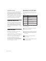
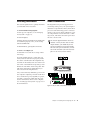
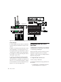
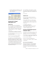
Digidesign
96i I/O Guide
Digidesign
2001 Junipero Serra Boulevard
Daly City, CA 94014-3886 USA
tel: 650·731·6300
fax: 650·731·6399
Technical Support (USA)
tel: 650·731·6100
fax: 650·731·6384
Product Information (USA)
tel: 650·731·6102
tel: 800·333·2137
International Offices
Visit the Digidesign Web site
for contact information
Web Site
www.digidesign.com
Copyright
This guide is copyrighted ©2003 by Digidesign, a division of
Avid Technology, Inc. (hereafter “Digidesign”), with all rights
reserved. Under copyright laws, this guide may not be
duplicated in whole or in part without the written consent of
Digidesign.
DIGIDESIGN, AVID and PRO TOOLS are trademarks or
registered trademarks of Digidesign and/or Avid Technology,
Inc. All other trademarks are the property of their respective
owners.
All features and specifications subject to change without
notice.
PN 910611738-00 REV A 09/03
Communications & Safety Regulation Information
Compliance Statement
The model 96i complies with the following standards
regulating interference and EMC:
• FCC Part 15 Class A
• EN55103 – 1, environment E4
• EN55103 – 2, environment E4
• AS/NZS 3548 Class A
Radio and Television Interference
This equipment has been tested and found to comply with the
limits for a Class A digital device, pursuant to Part 15 of the
FCC Rules.
Communications Statement
This equipment has been tested to comply with the limits for a
Class A digital device. Changes or modifications to this product
not authorized by Digidesign, Inc., could void the Certification
and negate your authority to operate the product. This product
was tested for CISPR compliance under conditions that
included the use of peripheral devices and shielded cables and
connectors between system components. Digidesign
recommends the use of shielded cables and connectors
between system components to reduce the possibility of
causing interference to radios, television sets, and other
electronic devices.
Safety Statement
This equipment has been tested to comply with USA and
Canadian safety certification in accordance with the
specifications of UL Standards; UL1419 and Canadian CSA
standard; CSA C22.2 No.1-M90. Digidesign Inc., has been
authorized to apply the appropriate UL & CUL mark on its
compliant equipment.
Important Safety Instructions
When using electric or electronic equipment, basic precautions
should always be followed, including the following:
• Read all instructions before using this equipment.
• To avoid the risk of shock, keep this equipment away from
rain water, and other moisture. Do not use this equipment
if it is wet.
• The equipment should only be connected to the correct
rating power supply as indicated on the product.
• Do not attempt to service the equipment. There are no
user-serviceable parts inside. Please refer all servicing to
authorized Digidesign personnel.
• Any attempt to service the equipment will expose you to a
risk of electric shock, and will void the manufacturer’s
warranty.
• The product should be connected only to the correct power
supply as indicated on the product.
Warning!
• HD audio interfaces need room at their sides to maintain
proper air flow and cooling.
• Do not install these units into a rack or other enclosure that
doesn't leave room on either side for the unit fans.
• Do not block the sides of the units (where fans are), or
disconnect the fan.
• If the units are racked up in a case, remove all lids, doors,
or covers before operating the units.
• Failure to do so can result in the units overheating very
quickly, which can permanently damage them.
contents
Chapter 1. Introduction to the 96i I/O . . . . . . . . . . . . . . . . . . . . . . . . . . . . . . . . . . . . . . . . . 1
What’s Included . . . . . . . . . . . . . . . . . . . . . . . . . . . . . . . . . . . . . . . . . . . . . . . . . . . . . . . . . 1
System Requirements . . . . . . . . . . . . . . . . . . . . . . . . . . . . . . . . . . . . . . . . . . . . . . . . . . . . . 1
Digidesign Registration . . . . . . . . . . . . . . . . . . . . . . . . . . . . . . . . . . . . . . . . . . . . . . . . . . . . 2
About this Guide . . . . . . . . . . . . . . . . . . . . . . . . . . . . . . . . . . . . . . . . . . . . . . . . . . . . . . . . . 2
About www.digidesign.com . . . . . . . . . . . . . . . . . . . . . . . . . . . . . . . . . . . . . . . . . . . . . . . . . 3
Chapter 2. 96i I/O Hardware Overview . . . . . . . . . . . . . . . . . . . . . . . . . . . . . . . . . . . . . . . . 5
The 96i I/O Front Panel . . . . . . . . . . . . . . . . . . . . . . . . . . . . . . . . . . . . . . . . . . . . . . . . . . . . 5
96i I/O Back Panel . . . . . . . . . . . . . . . . . . . . . . . . . . . . . . . . . . . . . . . . . . . . . . . . . . . . . . . 7
Chapter 3. Installing and Configuring the 96i . . . . . . . . . . . . . . . . . . . . . . . . . . . . . . . . . . . 9
Installing the 96i . . . . . . . . . . . . . . . . . . . . . . . . . . . . . . . . . . . . . . . . . . . . . . . . . . . . . . . . . 9
Powering Up Your System . . . . . . . . . . . . . . . . . . . . . . . . . . . . . . . . . . . . . . . . . . . . . . . . . 10
Checking Installation . . . . . . . . . . . . . . . . . . . . . . . . . . . . . . . . . . . . . . . . . . . . . . . . . . . . . 11
Audio Connections . . . . . . . . . . . . . . . . . . . . . . . . . . . . . . . . . . . . . . . . . . . . . . . . . . . . . . 11
Configuring the 96i I/O in Pro Tools . . . . . . . . . . . . . . . . . . . . . . . . . . . . . . . . . . . . . . . . . . 12
Index . . . . . . . . . . . . . . . . . . . . . . . . . . . . . . . . . . . . . . . . . . . . . . . . . . . . . . . . . . . . . . . . . . . . . 15
Contents
iii
iv
96i I/O Guide
chapter 1
Introduction to the 96i I/O
The Digidesign 96i I/O is a 16-input, 2-output
digital audio interface, featuring 24-bit analogto-digital (A/D) and digital-to-analog (D/A) converters.
The 96i I/O supports sampling rates up to
96 kHz for superior dynamic range and low
noise floor. The 96i I/O is the ideal audio interface to input multiple MIDI sound modules,
samplers, synthesizers, and other sound sources
into Pro Tools|HD.
96i I/O Features
• 16 discrete input channels and two output
channels, with 4-segment LED meters on each
channel. Input and output features include:
• 16 channels of 24-bit, 96 kHz-capable analog input, with adjustable input sensitivity
• Two channels of 24-bit, 96 kHz-capable analog output, with selectable operating level
• Two channels of 24-bit, 96 kHz-capable
digital S/PDIF RCA input and output
• Loop Sync In and Out
What’s Included
• 96i I/O
• DigiLink cable (1.5 feet [0.46m])
• BNC cable (1.5 foot [0.46m])
System Requirements
The 96i I/O is for Pro Tools|HD systems only,
and can be used as the only audio interface in a
Pro Tools|HD system (no other audio interface
present), or as an expansion I/O with a 192 I/O,
192 Digital I/O, 96 I/O, or other 96i I/O audio
interface.
The 96i I/O cannot be used in standalone
mode (it must be used with a Pro Tools|HD
system).
The 96i I/O does not provide a Legacy port. For
more information on connecting the 96i I/O,
see Chapter 3, “Installing and Configuring the
96i.”
• External Clock In and Out
• Expansion DigiLink port
Chapter 1: Introduction to the 96i I/O
1
Compatibility Information
Conventions Used in This Guide
Digidesign can only assure compatibility and
provide support for hardware and software it
has tested and approved. For a list of Digidesignqualified computers, operating systems, hard
drives, and third-party devices, refer to the latest
compatibility information on the Digidesign
Web site (www.digidesign.com/compato).
Digidesign guides use the following conventions to indicate menu choices and key commands:
Convention
Action
File > Save
Session
Choose Save Session from the
File menu
Control+N
While pressing the Control key,
press the N key
Control-click
While pressing the Control key,
click the mouse button
Right-click
(Windows)
Click with the right mouse button
Digidesign Registration
Make sure to complete and return the registration card included with your Digidesign audio
interface. Registered users will receive periodic
software update and upgrade notices. Refer to
the registration card for information on technical support.
About this Guide
This guide provides a basic overview of the
96i I/O features and functionality.
Complete instructions for connecting and configuring your Pro Tools|HD-series system are located in the Getting Started with HD Guide.
For additional information about using
Pro Tools software to route your interface inputs
and outputs too Pro Tools inputs and outputs,
see the Pro Tools Reference Guide.
2
96i I/O Guide
The following symbols are used to highlight important information:
User Tips are helpful hints for getting the
most from your system.
Important Notices include information that
could affect your data or the performance of
your system.
Shortcuts show you useful keyboard or
mouse shortcuts.
Cross References point to related sections in
other Digidesign guides.
About www.digidesign.com
The Digidesign Web site (www.digidesign.com)
is your best source for information to help you
get the most out of your Pro Tools system. The
following are just a few of the services and features available.
Support Contact Digidesign Technical Support
or Customer Service; download software updates and the latest online manuals; browse the
Compatibility documents for system requirements; search the online Answerbase; join the
worldwide Pro Tools community on the Digidesign User Conference.
Training and Education Become a certified
Pro Tools Operator or Expert; study on your
own using courses available online, or find out
how you can learn in a classroom setting at a
certified Pro Tools Training Center.
Products and Developers Learn about Digidesign
products; download demo software; learn about
our Development Partners and their plug-ins,
applications, and hardware.
News and Events Get the latest news from
Digidesign; sign up for a Pro Tools demo.
To learn more about these and other resources
available from Digidesign, visit our Web site
(www.digidesign.com).
Chapter 1: Introduction to the 96i I/O
3
4
96i I/O Guide
chapter 2
96i I/O Hardware Overview
The 96i I/O Front Panel
Figure 1. 96i I/O front panel
Power Switch and LED Ring
Loop Master LED
This button turns the 96i I/O on and off.
The LOOP MASTER LED indicates which HD audio interface is the master Pro Tools peripheral.
Loop Master defaults to the first HD I/O connected to the HD Core card. Loop Master will always be lit in systems with a single interface.
The LED ring around the power button will light
green to indicate that the unit has powered up
successfully and is connected to an active
Pro Tools|HD system. If the LED ring is orange,
the unit has power, but the computer it is connected to is shut down.
Sample Rate LEDs
These LEDs display the current Pro Tools sample
rate, either 96 kHz, 88.2 kHz, 48 kHz, or
44.1 kHz. (The 96i I/O will go offline whenever
the current Pro Tools sample rate is 176.4 kHz or
192 kHz.)
In expanded systems, only one HD I/O can be
Loop Master at a time. When you change the
clock source to an external clock on a particular
HD I/O or a SYNC I/O, that HD I/O (or
SYNC I/O) will automatically become the Loop
Master and all other HD I/Os in the chain will be
switched to Loop Slave mode (see “Sync Mode
LEDs” on page 6).
Chapter 2: 96i I/O Hardware Overview
5
Sync Mode LEDs
The SYNC MODE LEDs indicate the current
Pro Tools Clock Source and Sync mode. Choices
include the following:
INT (Internal) Indicates the 96i I/O is the
Pro Tools clock master.
DIG (Digital) Indicates the 96i I/O S/PDIF port is
providing master clock to Pro Tools.
LOOP (Loop Sync) Indicates 96i I/O is in Loop
Slave mode, and is clocking to the current Loop
Master device. See also “Loop Master LED” on
page 5.
EXT (External) Indicates the 96i I/O EXT
CLOCK IN port is providing master clock to
Pro Tools.
For more information, see the Getting Started
with HD Guide.
Input and Output LEDs and Meters
16 sets of four-segment LEDs indicate signal
level for each of the 96i I/O input channels.
These LEDs are calibrated at –42 dB, –18 dB,
–6 dB, and 0 dB, respectively, referenced to Full
Scale digital.
Full Scale digital (0 dBFS) does not always
indicate signal clipping levels; please use the
on-screen meters in Pro Tools to determine
whether a signal is clipping. For more information, see the Getting Started Guide with
HD Guide.
Two additional LEDs, located to the left of the
meters, indicate whether the meters display input or output levels; the meters indicate input
levels by default, and can be switched from
within the Hardware Setup dialog in Pro Tools.
6
96i I/O Guide
96i I/O Back Panel
INPUTS 1-4
INPUTS 5-16
SW CTRL GAIN
1
2
OUTPUT
+4dBu/–12dBV
3
4
5
6
+4dBu/–10dBV
7
9
11
13
15
1
8
10
12
14
16
2
Figure 2. 96i I/O back panel
Analog Inputs
Analog Outputs
96i I/O provides 16 balanced, 1/4-inch TRS jacks
for analog audio input connections.
These are balanced, 1/4-inch TRS jacks for analog audio output connections.
Inputs 1–4 provide six stages of software-adjustable operating level sensitivity. Choices
range from –12.0 dBV to +4.0 dBu, with default
sensitivity set to –8 dBV.
The 96i I/O analog outputs feature 24-bit digital-to-analog converters. Output operating levels are software-switchable between +4 dBu and
–10 dBV operating levels.
◆
Inputs 5–16 are software-switchable between
–8 dBV and +4 dBu operating level sensitivity.
◆
The 96i I/O inputs can accommodate a wide
range of line-level devices including synthesizers, samplers, sound modules, and effects devices.
All analog inputs are balanced, and feature 24bit, 96 kHz analog-to-digital converters, with
14 dB of headroom above +4 dBu (fixed, requiring no calibration). Unbalanced connections are
supported with the use of standard 1/4-inch
mono phone plugs.
96i I/O input wiring for balanced connections
Tip
Hot (or +)
Ring
Cold (or –)
Sleeve
ground
The 96i I/O is factory calibrated at +14 dB headroom, yielding a maximum output level of
+18 dBu when in +4 dBu operating mode.
When set to –10 dBV operating mode, maximum output level is +4 dBV.
Unbalanced connections are supported through
the use of standard 1/4-inch TRS mono phone
plugs.
96i I/O output wiring for balanced connections
Tip
Hot (or +)
Ring
Cold (or –)
Sleeve
ground
Chapter 2: 96i I/O Hardware Overview
7
S/PDIF Digital In and Out
These are unbalanced RCA jacks that accept and
output a stereo S/PDIF digital data stream.
S/PDIF supports up to 24-bit audio at up to
96 kHz.
S/PDIF input can be chosen as the input source
for channels 1–2 in the Hardware Setup dialog.
S/PDIF output is mirrored to analog outputs 1–2.
To maintain data integrity and minimize jitter,
use only 75-ohm coaxial cable.
Loop Sync In and Out
Loop Sync is a dedicated Pro Tools clock loop for
synchronizing multiple HD-series interfaces together. The Loop Sync In and Out ports are standard BNC connectors that output a 1x Loop
Sync clock signal. Loop Sync should only be
used to chain multiple HD-series peripherals together.
Loop Sync uses a word clock signal based on
sampling rates of either 44.1 kHz or 48 kHz. As
sample rates increase in the system, Loop Sync
continues to operate at a base rate of 44.1 kHz or
48 kHz (44.1 kHz for 88.2 kHz sessions, 48 kHz
for 96 kHz sessions).
EXT. CLOCK In and Out
The External Clock I/O ports are standard BNC
connectors that receive and output a word clock
signal. These ports can be used to synchronize
the 96i I/O to any device that requires (or provides) word clock.
8
96i I/O Guide
The External Clock In and Out are configured in
the Hardware Setup dialog.
Because the Loop Sync and Word Clock ports
pass crucial timing information, you must
use high-quality 75-ohm coaxial cables for
making connections. RG59 or better quality
cable is recommended
Primary Port
The Primary Port is used to connect the 96i I/O
to your HD cards, or to another HD-series audio
interface, using a DigiLink cable. When the
96i I/O is the only audio interface in the system,
the Primary Port is connected directly to the HD
Core card. When 96i I/O is used as an additional
I/O in an expanded Pro Tools|HD system, the
96i I/O Primary Port can be connected to an
HD Accel Card or HD Process Card, or to the Expansion port on a 192 I/O, 192 Digital I/O, or
96 I/O. (For more information, see Chapter 3,
“Installing and Configuring the 96i.”)
Expansion Port
The Expansion Port is used to connect an additional HD-series I/O to the 96i I/O. Using a DigiLink cable (one is included with each HD-series
interface), another 96i I/O can be connected to
the Expansion port for an additional 16 channels of input to your HD Core card (or other).
AC Power
This connector accepts a standard AC power cable. The 96i I/O is auto power-selecting (100V to
240V) and will automatically work with a standard modular cable to connect to AC power receptacles in any country.
chapter 3
Installing and Configuring the 96i
This chapter provides basic instructions for installing a 96i I/O, and configuring its operating
levels.
See the Getting Started with HD Guide for
complete system installation and configuration instructions.
If you are adding the 96i I/O to an existing
system, see the Expanded Systems Guide.
Installing the 96i
Power
To connect AC power to the 96i:
■ Using the AC power cable included with the
unit, connect the 96i I/O to a standard AC
power receptacle. The 96i I/O is auto power-selecting (100V to 240V) and will work automatically when plugged into an AC power receptacle
in any country.
DigiLink Connections
All installations require the following AC power
and DigiLink connections. Expanded systems
also require Loop Sync connections.
DigiLink connections differ depending on
whether the 96i I/O is the primary audio interface in the system, or if it is being added as an
expansion I/O to an existing HD system.
Before You Begin
To connect the 96i I/O as the primary interface in
a Pro Tools|HD system:
Turn off your computer, hardware interfaces, monitoring system, hard drives, and
peripherals. Making connections while
power is on can damage your system.
1 Connect one end of the included DigiLink ca-
ble to the Primary Port on the 96i I/O.
2 Connect the other end of the DigiLink cable
to the DigiLink port on the HD Core card. (See
the Getting Started with HD Guide for complete
installation instructions.)
Chapter 3: Installing and Configuring the 96i
9
To connect the 96i I/O to an existing
Pro Tools|HD-series system:
1 Connect one end of a DigiLink cable to the
Primary Port of the 96i I/O.
2 Connect the other end of the DigiLink cable
to one of the following:
• An available DigiLink port on an HD Accel
or HD Process card.
– or –
• An available Expansion Port on the existing HD I/O.
If you have at least one 192 I/O or
192 Digital I/O in your system configuration, it must be the primary audio interface
and Loop Sync master.
For additional information, see the Expanded Systems Guide
Loop Sync Connections
3 If using more than two HD I/Os, repeat for ad-
ditional interfaces and finish by connecting the
Loop Sync Out of the last interface to the Loop
Sync In of the primary interface to complete the
Loop Sync chain.
See the Getting Started with HD Guide for
more information about Loop Sync.
Powering Up Your System
In order for Pro Tools to communicate properly
with audio interfaces and other peripherals, it is
important that you start up and shut down your
system in the following order:
Power up your system in this order:
1 Turn on your Pro Tools hard drives.
2 Turn on synchronization or other MIDI pe-
ripherals or interfaces.
(For Expanded Systems Only)
3 Turn on your 96i I/O and any other Pro Tools
Loop Sync must be connected whenever multiple HD-series audio interfaces are present in a
system. (If the 96i I/O is the only audio interface
present, skip this section and proceed to “Powering Up Your System” on page 10.)
audio interfaces. On power up, the status LEDs
will flash. Wait at least fifteen seconds for the
96i I/O to initialize, and the status LEDs to stop
blinking. If properly connected, the ring around
the power switch will be orange while the computer is powered down.
To connect Loop Sync between two or more HDseries audio interfaces:
1 Connect the BNC cable from the Loop Sync
Out port of the primary HD I/O (192 I/O,
192 Digital I/O, 96 I/O, or other 96i I/O) to the
Loop Sync In port of the 96i I/O.
2 Connect the Loop Sync Out of the 96i I/O to
the Loop Sync In of the primary HD I/O (if using
only two interfaces), or to the Loop Sync In of
the next HD I/O if using more than two.
4 Turn on your computer. All power LED rings
on HD I/O should switch to green. This signifies
that the HD I/Os are properly connected.
Power down your system in this order:
1 Quit Pro Tools.
2 Shut down the computer.
3 Power off your audio interfaces.
4 Turn off any synchronization, MIDI, or other
peripherals or interfaces.
5 Turn off your drives.
10
96i I/O Guide
Checking Installation
Audio Connections
This section explains how to quickly check that
your installation was successful.
The diagrams below provide suggestions for
connecting studio gear to your system. Figure 1
illustrates a setup without a mixer, where effects
processors and monitoring gear are connected
directly to the 96i I/O. Figure 2 illustrates a studio setup with the 96i I/O connected to a mixing console, with effects and other gear routed
into the console as well.
To check installation using DigiTest:
1 Start up your computer (see “Powering Up
Your System” on page 10).
2 Launch DigiTest.
3 Ensure that any and all HD cards and HD I/Os
are identified properly. If not, see the Getting
Started with HD Guide.
4 When finished, quit DigiTest and restart.
To check or reconfigure I/O:
1 Launch Pro Tools and choose Setup > Hard-
The 96i I/O supports hardware inserts on
channels 1–2 only. Because this uses both
output channels, you should only use the
96i I/O for hardware inserts when another
HD-series I/O is present (otherwise you will
not be able to monitor your work when outputs 1–2 are in use for insert returns).
ware Setup.
2 Use the Identify button to verify that your
newly-added 96i I/O has been properly identified. Select each HD I/O in the Peripherals list,
and click on the Identify radio box in the lower
left corner of the Hardware Setup dialog to illuminate all of the LEDs on the front panel. This
will clearly demonstrate which HD I/O you
have selected in the Peripherals list.
3 If you encounter any difficulties, power down
Monitoring System
Outputs 1–2
Inputs 1–16 from synths, sound modules,
samplers, and other sources
the computer completely, and turn off all interfaces. Check all AC power, DigiLink, Loop Sync,
and audio connections. Then turn the power
back on all interfaces and boot the computer.
See “Powering Up Your System” on page 10 for
more information.
Figure 1. 96i I/O studio setup without a mixing console
Chapter 3: Installing and Configuring the 96i
11
INPUTS 1-4
INPUTS 5-16
OUTPUT
SW CTRL GAIN
+4dBu/–12dBV
+4dBu/–10dBV
to 96i I/O inputs 1–16
Low-level sources
to inputs 1–4
channel outputs
96i I/O Out 1–2
Main
Outs
Tape
returns
or inputs
preamp or D.I.
Monitoring System
Synths,
sound
modules,
and other
to mixer
inputs
Monitor
Outs
Sends and Returns
Effects Devices
Figure 2. 96i I/O studio setup with a mixing console
Connection Tips
Connect digital recorders such as CD and DAT
recorders using the S/PDIF RCA outputs on the
96i I/O.
◆
Inputs 1–4 offer the greatest amount of sensitivity adjustment, so use these inputs for lowlevel signals from less powerful devices (such as
older keyboards, samplers, and sound modules).
◆
◆ Use inputs 5–16 for professional grade devices
with higher output levels.
◆ Consider connecting the 96i I/O to a highquality patch bay for the greatest flexibility. A
patch bay will let you quickly route signals to inputs 1–4 or 5–16 as needed; use inputs 1–4 when
you need the most control over input levels. Use
inputs 5–16 for all other input needs.
Configuring the 96i I/O in
Pro Tools
Configuring the 96i I/O with Pro Tools includes
adjusting input and output gain, and selecting
(or deselecting) S/PDIF input.
The 96i I/O, when correctly connected, is automatically recognized by Pro Tools when it
launches. 96i I/O settings are configured in the
Hardware Setup window.
To configure the 96i I/O in Pro Tools:
1 Choose Setups > Hardware.
2 Configure the Hardware Setup parameters for
the 96i I/O.
• For input gain, see “Adjusting 96i I/O Input and Output Levels” on page 13.
12
96i I/O Guide
• For analog/digital input switching, see “Enabling S/PDIF Digital Input for Channels 1
and 2” on page 13.
5 For each input or pair of inputs 5–16 being
used, select –8 dBV or +4 dBu as appropriate to
best match the output level of the connected devices.
6 Click Done.
Output Levels
The 96i I/O analog outputs can operate at
–10 dBV or +4 dBu, as configured in the Hardware Setup dialog.
Hardware Setup controls for the 96i I/O
Adjusting 96i I/O Input
and Output Levels
Input Levels
The 96i I/O input levels are adjustable in
Pro Tools. Inputs 1–4 provide multi-level sensitivity adjustment. Inputs 5–16 provide two selectable settings. The available settings let the
96i I/O accommodate a variety of equipment
output levels.
To adjust input level sensitivity on the 96i I/O:
1 Connect instrument and other devices to the
96i I/O analog inputs.
2 In Pro Tools, choose Setups > Hardware.
3 Choose 96i I/O in the Peripherals list.
4 For Inputs 1–4, set the input trim slider to
match the output level of the connected instrument. Choices range from –12 dBV to +4 dBu.
(Hardware inputs and outputs are muted whenever the Hardware Setup window is open. Check
your settings by closing the Hardware Setup
window and then playing the input source. Return to the Hardware Setup window if further
adjustments are needed.)
Analog output is mirrored to S/PDIF outputs
1–2, making it easy to connect CD, DAT, and
other stereo digital recorders that support RCA
S/PDIF input.
To set Output operating level:
■ In the Hardware Setup dialog, choose the
96i I/O in the Peripherals list, then select
–10 dBV or +4 dBu, as desired.
Enabling S/PDIF Digital Input for
Channels 1 and 2
You can choose to use either the analog or digital inputs as sources for 96i I/O channels 1–2.
Only channels 1–2 can access the S/PDIF inputs.
To select analog or digital input for channels 1–2:
1 Choose Setups > Hardware.
2 Choose 96i I/O in the Peripherals list.
3 Click to set Ch 1–2 Input to Analog or S/PDIF,
as appropriate.
96i I/O and I/O Setup Guidelines
The 96i I/O only supports analog and digital
switching for channels 1–2, from within the
Hardware Setup and I/O Setup dialogs. The
96i I/O does not support path remapping within
I/O Setup.
Chapter 3: Installing and Configuring the 96i
13
14
96i I/O Guide
index
Numerics
I
24-bit 1
96-kHz 1
Identify button 11
input sensitivity 13
setting 13
inputs
analog 7
S/PDIF digital 8
word clock 8
installation 9
A
AC power 9
power-up sequence 10
B
balanced
inputs 7
base rate 8
C
Clock Source 6
connections 9
AC power 9
DigiLink 9
Loop Sync 10
L
Loop Master 5
Loop Sync
connections 10
In and Out 8
M
Meters 6
O
D
DigiLink 9
expansion 8
Primary port 8
DigiTest 11
E
Expansion
DigiLink 8
port 8
External Clock
In port 8
Out port 8
H
outputs
analog 7
S/PDIF digital 8
word clock 8
P
Peripherals list 11
power down
order 10
procedures 10
Power Switch and LED Ring 5, 10
power up
order 10
procedures 10
sequence 10
Hardware Setup 6, 11
Index
15
R
registration 2
S
S/PDIF 8
Sample Rate 5
sensitivity 13
setting input gain level 13
studio setup (no mixer) 11
Sync Mode 6
synchronization 10
U
unbalanced
input 7
output 7
W
wiring
TRS balanced input 7
TRS balanced output 7
word clock 8
16
96i I/O Guide