1
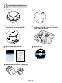
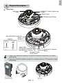
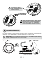
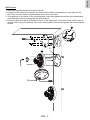
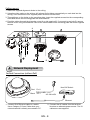
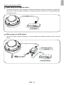
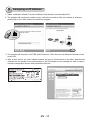
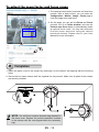
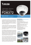
English
Warning Before Installation
Power off the Network Camera as
soon as smoke or unusual odors are
detected.
Refer to your user's manual for the
operating temperature.
Contact your distributor in the event of
occurrence.
Do not place the Network Camera on
unsteady surfaces.
Do not touch the Network Camera
during a lightning storm.
Do not insert sharp or tiny objects
into the Network Camera.
Do not drop the Network Camera.
EN - 1
1
Package Contents
FD8372
Mounting Plate
Alignment Sticker /
Ceiling Hole Template Sticker
L-type Hex Key Wrench / Moisture
Absorber / Screws / Hex Nut / Doublesided Tape / AV Cable
Quick Installation Guide /
Warranty Card
Software CD
5 1 0 0 0 02 2 1 G
Waterproof Connector & Bushing
EN - 2
English
2
Physical Description
Inner View
Vari-focal
Lens
IR LEDs (15 units, effective up
to 20m)
Black Cover
Tilt Adjustment Screw
Micro SD/SDHC Card Slot
Reset
Jumpers
Button
Microphone Video Output
NTSC
Internal
60Hz
External
1
PAL
50Hz
2
Audio/Video
Out (green)
Microphone In
(pink)
Ethernet 10/100
RJ45 Socket
General I/O Terminal
Block
1. There is no internal microphone. Connect an external microphone if you need
audio inputs.
2. Use the included AV cable to connect to a camera tester or LCD monitor to begin
initial setup.
LCD Monitor/
Camera tester
EN - 3
AV Out
Record the MAC address
under the camera base before
installing the camera.
Replace the side opening cover with the included
side outlet bushing if you want to route cables
from the side of camera. The 1/2" protection
conduits and tubing are separately purchased.
3
Hardware Installation
First, use the included T20 hex key wrench to loose the four screws and detach the dome cover from the
camera base. Follow the steps below to install the camera either to a ceiling or a wall.
IMPORTANT: Dome cover should be removed because if it should fall during the installation
process, physical injury could occur to your co-workers.
Top View
Dome Cover
Dome Cover Retainer
EN - 4
English
Cabling Assembly
Connect power lines and if you have external devices such as sensors and alarms, make the connection
from the general I/O terminal block.
Pin Definitions
Top View
1 2 3 4 5 6 7 8
1
2
3
4
5
6
7
8
DO+ (12V)
DODI1+
DI2+
DI3+
DIAC24V_1
AC24V_2
Power and IO cables pass through a waterproof connector. The
Ethernet cable should be routed through a rubber seal plug. All
cables are user-supplied.
Power output, 12V DC: max. load is 50mA.
For Ethernet
Cable
For Power & IO Cables
Waterproof Connector
(A)
Sealing Nut (A)
(B)
Housing (B)
(D)
Seals (C)
(E)
Seal (D)
Screw Nut (E)
Hex Nut (F)
(F)
Assembling Steps
1.Disassemble the components of the waterproof
connector into parts (A) ~ (F) as shown above.
waterproof connector (F --> E --> D --> B -->
A) as previously described. Refer to the pin
definition to connect them to the general I/O
terminal block. Note: The recommended cable
gauge is 2.0 ~ 2.8 mm.
2. Place the screw nut (E) on the Power and GPIO
opening.
3.Feed the power cables through the waterproof
connector (F --> E --> D --> B --> A) as the
illustration shows. Then connect the power
cables to the power source. Note: There are 8
holes on the seal (D), and the widest holes with
a crack on the side are specific for power cables.
4.If you have external devices such as sensors
and alarms, feed the cables through the
5. Push the seal (D) into the housing (B).
6.Insert the seals (C) into unused holes on the
seal (D) to avoid moisture.
7.Secure the sealing nut (A) tightly and hex nut
(F) from the bottom of the camera.
EN - 5
Connecting RJ45 Ethernet Cable
RJ45 Cable Dimension (unit: mm)
Recommended cable gauge: 24AWG (0.51 mm)
Assembling Steps
Rubber Seal
Plug
1
1. Drill a hole on the rubber seal
plug and insert an Ethernet cable
through the opening.
2. Strip part of the sheath from the
Ethernet cable.
2
3. You will need an RJ45 crimping tool to
attach the Ethernet wires to a connector.
When done, connect the cable to the
camera’s Ethernet RJ45 socket.
3
o: white/orange stripe
O: orange solid
g: white/green stripe
B: blue solid
b: white/blue stripe
G: green solid
br: white/brown stripe
BR: brown solid
o
O
g
B
b
G
br
BR
1
2
3
4
5
6
7
8
4. Press the Ethernet cable into the routing path at
the bottom of the camera so that the cable will not
get in the way when the metal mounting plate is
attached.
EN - 6
4
English
Wall mount
1. Attach the supplied alignment sticker to the wall.
2. Using the circle marks on the sticker, drill at least 2 pilot holes symmetrically on each side into the
wall. Then hammer the four supplied plastic anchors into the holes.
3. Through three or four holes on the mounting plate, insert the supplied screws into the corresponding
holes and secure the mounting plate with a screwdriver.
4. Feed the cables through the triangular cutout A or side opening B. If you want to use hole B, remove
the side cover using a screwdriver. Secure the camera base to the mounting plate with three supplied
screws.
1
3
4
B
EN - 7
A
2
Ceiling mount
1. Attach the supplied alignment sticker to the ceiling.
2. Using the circle marks on the sticker, drill at least 2 pilot holes symmetrically on each side into the
ceiling. Then hammer the four supplied plastic anchors into the holes.
3. Through three or four holes on the mounting plate, insert the supplied screws into the corresponding
holes and secure the mounting plate with a screwdriver.
4. Feed the cables through the triangular cutout A or side opening B. If you want to use hole B, remove
the side cover using a screwdriver. Secure the camera base to the mounting plate with three supplied
screws.
A
1
2
3
4
4
B
Network Deployment
General Connection (without PoE)
Red
Pin 2
Black
Pin 1
Non-PoE Switch
POWER
COLLISION
1
2
3
4
5
LINK
RECEIVE
PARTITION
AC 24V±10%
Ethernet
1. Connect RJ45 Ethernet cable to a switch.
Use a Category 5 Cross Cable when your
network camera is directly connected to PC.
2. Connect the AC cables from the terminal
block as an alternate power source. The IO
cables are user-supplied.
EN - 8
English
Power over Ethernet (PoE)
When using a PoE-enabled switch
The Network Camera is PoE-compliant, allowing transmission of power and data via a single Ethernet cable. Follow the below illustration to connect the Network Camera to a PoE-enabled switch
via Ethernet cable.
POWER
COLLISION
1
2
3
4
5
LINK
RECEIVE
PARTITION
PoE Switch
When using a non-PoE switch
Use a PoE power injector (optional) to connect between the Network Camera and a non-PoE
switch.
PoE Power Injector
(optional)
POWER
COLLISION
1
2
3
4
5
LINK
RECEIVE
PARTITION
Non-PoE Switch
EN - 9
5
Assigning an IP Address
1. Install “Installation Wizard 2” from the Software Utility directory on the software CD.
2. The program will conduct an analysis of your network environment. After your network is analyzed,
please click on the “Next” button to continue the program.
Installation
Wizard 2
3. The program will search for VIVOTEK Video Receivers, Video Servers, and Network Cameras on the
same LAN.
4. After a brief search, the main installer window will pop up. Double-click on the MAC address that
matches the one printed on the camera label or the S/N number on the package box label to open a
browser management session with the Network Camera.
FD8372
0002D1083236
00-02-D1-08-32-36
192.168.5.109
0002D1083236
EN - 10
FD8372
English
6
Ready to Use
1. A browser session with the Network Camera should prompt as shown below.
2. You should be able to see live video from your camera. You may also install the 32-channel recording
software from the software CD in a deployment consisting of multiple cameras. For its installation
details, please refer to its related documents.
For further setup, please
refer to the user's
manual on the software
CD.
7
Adjusting the Lens
Based on the live image retrieved from the camera, adjust the camera lens by doing the following:
To adjust the viewing angle -- 3-axis mechanism design
1.Loosen the tilt adjustment screws and then turn the lens module up or down. Upon completion,
tighten the screw.
2. Turn the lens to adjust the image orientation.
Vertical Tilt 65°
2
Lens Horizontal
Pan 350°
Tilt Adjustment
Screws
Horizontal Pan
350°
1
EN - 11
To adjust the zoom factor and focus range
1. The camera comes with a motorized vari-focal lens
module. With a web console, you can enter the
Configuration > Media > Image > Focus page to
tune the image zoom and focus.
2.On this page, you can pull the Zoom and Focus
pointers, set up a Focus window, and use the
Perform auto focus button to automatically obtain
an optimal focus result. You may also manually
fine-tune zoom and focus using the various
functional buttons. Please refer to your User
Manual for more information.
Focus window
8
Completion
1.Attach the dome cover to the camera by combining it to the retainer and aligning with the mounting
holes.
2.Secure the four dome screws with the supplied hex key wrench. Make sure all parts of the camera
are securely installed.
1
2
2
NOTE: You will find a moisture absorber bag attached to
the dome cover. Replace the moisture absorber included
in the camera with the one shipped within the accessory
bag.
EN - 12