1
MODEL NO,
917.257281
ERR
Caution:
Read and follow
all Safety Rules
and instructmns
Before Operating
This Equipment
12.0
IC
ELECTRIC START
38" MOWER DECK
5
TRANS/_LE
LAWN TRACTO
• Assembly
oOperation
° Customer Responsibilities
° Service and Adjustment
, Repair Parts
Sears, Roebuck and Co., Chicago, iL 60684 U.S.A.
SAFETY
Safe Operation
Practices RULES
for Ride-On Mowers
IMPORTANT; THIS CUTTtNG MACHINE IS CAPABLE OF AMPUTATING HANDS AND FEET AND THROWING OBJECTS,
FAILURE TO OBSERVE THE FOLLOWING SAFETY INSTRUCTIONS COULD RESULT IN SERIOUS INJURY OR DEATH.
Io
GENERAL
•
Read, understand, and follow all instructionsin the manual
and on the machine before starting,
Only allow responsible adults, who are familiar with the
instructions, to operate the machine.
Clear the area of objects such as rocks, toys, wire, etc.,
which could be picked up and thrown by the blade,
Be sure the area isclear of other people before mowing. Stop
machine if anyone enters the area°
Never carp] passengers.
Do not mow in reverse unless absolutely necessary,. Always
look down and behind before and while backing,
Be aware of the mower discharge direction and do not point
it at anyone. Do not operate the mower without either the
entire grass cat_her or the guard in place.
Slow down before turning.
Never leave a running machine unattended. Always turn off
blades, set parking brake, stop engine, and remove keys
before dismounting,.
Turn off blades when not mowing.
Stop engine before removing grass catcher or unclogging
chute.
Mow only in daylight or good artificial lighL
Do not operate the machine while under the influence of
alcohol or drugs_
Watch for trafficwhen operating near or crossing roadways.
Use extra care when loading or unloading the machine into
a trailer or truck.
•
•
•
•
.
•
.
•
•
.
•
•
•
I1.
OPERATION
SLOPE OPERATION
I!1. CHILDREN
Tragic accidents can occur if the operator is not alert to the
presence of children_Children are often attracted to the machine
and the mowing activity. Never assume that children will remain
where you last saw them,.
°
.
°
•
°
•
Before and when backing, look behind and down for small
children_
Never' carry chiIdrem They may fall off and be seriously
injured or interfere with safe machine operation.
Never allow children to operate the machine_
Use extra care when approaching blind corners, shrubs,
trees, or other objects that may obscure vlsion.
IV. SERVICE
°
•
•
•
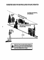
Slopes are a major factor related to loss-of-control and tipover
accidents, which can result in severe injuryor death. All slopes
require extra caution. Ifyoucannotbackupthes[opeorifyou
feel
uneasy on it, do not mow it.
.
DO:
•
•
•
°
°
•
Mow up and down slopes, not across.
Remove obstacles such as rocks, tree limbs, etc.
Watch for holes, ruts, or bumps. Uneven terrain could
overturn the machine° Ta/l grass can hfde obstacles.
•
Use slow speed_ Choose a lowgear so that youwill not have
to stop or shift while on the slope_
•
Follow the manufacturer's recommendations for wheel
weights or counterweights to improve stability.
•
Use extra care with grass catchers or other attachrnents_
These can change the stability of the machine.
.
Keep all movement on the slopes slow and gradual Do not
make sudden changes in speed or direction.
•
Avoid starting or stopping on a slope, If tires lose traction,
disengage the blades and proceed slowtystraight down the
slope.
DO NOT;
•
Donot turnon slopes unlessnecessary, and then,turn slowly
and gradua!ly downhill, if possible,
•
Do not mow near drop*offs, ditches, or'embankments The
mower could suddenly turn over if a wheel is over the edge
of a cliffor ditch, or if an edge caves in
°
Do not mow on wet grass_ Reduced traction could cause
sliding.
°
Do not try to stabilize the machine by putting your foot on the
ground.
•
Do not use grass catcher on steep slopes
Keep chtldrenout of the mowing area and underthe watchful
care of another responsible adulL
Be alert and turn machine offif children enter the area.,
-
Use extra care in handlinggasoline and other fuels. They are
flammable and vapors are explosive,
Use only an approved container,
Never remove gas cap or' add fuel with the engine
running_ Allow engine to cool before refueling, Do not
smoke.
Never refuel the machine indoors.
Never store the machine or fuel container inside where
there is an open flame, such as a water heater,
Never run a machine inside a closed area.
Keep nuts and bolts, especially blade attachment bolts,tight
and keep equipment in good condition.
Never tamper with safety devices,. Check their proper
operation regularly.
Keep machine free of grass, leaves, or other debris build-up.
Clean oil or' fuel spillage. Allow machine to cool before
storing,.
Stop and inspect the equipment [f you strike an object.,
Repair, if necessary, before restarting.
Never make adjustments or repairs with the engine running_
Grass catcher components are subjectto wear, damage, and
deterioration, which could expose moving parts or allow
objects to be thrown. Frequently check components and
replace with manufacturer's recommended parts, when necessary.
Mower blades are sharp and can cut° Wrap tl_e blade(s) or
wear gloves, and use extra caution when servicing them.
Check brake operation frequently_ Adjust and service as
required.
Look for this symbol to point out important safety
precautions.
It means
CAUTIONH!
BECOME ALERT!!!
YOUR
SAFETY IS INVOLVED,
CAUTION:
Always disconnect spark
plug wire and place wire where it cannot
contact spark plug In order to prevent
accidental starting when setting up,
transporting,
repairs,
adjusting
or
making
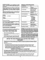
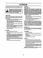
CONGRATULATIONS
on your purchase
of a Sears
Tractor. It has been designed, engineered and manufactured to give you the best possible dependability and
penormanceo
:bRODUCT SPECiFICATiONS
12.0
GASOLINECAPACITY:
5 QUARTS
UNLEADEDREGULAR
OIL (3.0 PINTS):
SAE 30 (above32°F)
5W30 (below32°F)
SPARKPLUG (GAP,030IN.):
CHAMPION RJ-lgLM
STD361458
VALVE CLEARANCE:
INTAKE .005 - .007 IN.
EXHAUST .009 - .01t IN.
GROUND SPEED:
FORWARD
1st 1.10 MPH
2nd 2.00 MPH
3rd 3.00 MPH
4th 4.00 MPH
5th 5.00 MPH
REVERSE: 1.50MPH
TIRE PRESSURE:
FRONT: 14 PSI
REAR: 10 PSi
CHARGINGSYSTEM:
3 AMPS BATTERY
5 AMPS HEADLIGHTS
BLADEBOLTTORQUE:
30*35 FT. LBS.
..............
Should you experience any problem you cannot easily
remedy, please contact your nearest Sears Service
CenteriDepartmento We have competent, well-trained
technicians and the proper tools to service or repair this
unit.
Please read and retain this manual. The instructions will
enable you to assemble and maintain your unit properly°
Always observe the "SAFETY RULES".
MODEL
NUMBER
HORSEPOWER:
917.257281
SERIAL
NUMBER
DATEOFPURCHASE
THE MODELAND SERIALNUMBERSWILLBE
ON A PLATE UNDER THE SEAT.
,
,, .......
WARNI.NG: This unitis equipped wlth an Internal comb.uson engine ano snould not be usea on or near any unlm:
proved forest-covered t brush-covered or gras.s-coverea
lana unless the engine s exhaust system is equipped with
a spark arrester meeting applicable local or state laws lif
any). ira spart_arrester =sused, itshould be maintainea m
effective working order by the operator.
RESPONSIBIUTIES
II
Read and observe the safety rules.
0
Followa regularschedutein maintaining, caring for and
using your unit.
In the state of California the above is required by law
(Section 4442 of the California P,ublic Hesources Code).
Other states may have similar laws. Federal laws applyon
Teaeral lanaso P, spark arres_er mr the muttler is available
through your nearest Sears Authorized Service Center
(See REPAIR PARTS section of this manual).
Followthe instructionsunder "Customer Responsibilities" and "Storage" sections of this owner's manual,
;;
,
AGREEMENT
A Sears Maintenance Agreement is available on this product. Contact your nearest Sears store for details.
CUSTOMER
,
.,.
FOUND
YOU SHOULD RECORD BOTH SERIAL NUMBERAND
DATE OF PURCHASE AND KEEP IN A SAFE PLACE
FOR FUTURE REFERENCE.
MAINTENANCE
H
;
..............
:
....
;;;
;
;
Hi
ill
.................
::....
.........
:
:
LIMITED TWO YEAR WARRANTY ON ELECTRIC START RIDING
EQUIPMENT
Fortwo (2) yearsfrom thedate of purchase,if thLsridingequipmentts maintained,lubricated and tunedup accordingtothe
instructions
in the owner'smanuaJ,Searswillrepairor replace,free ofcharge,any partsfound to be defectiveIn material or
workmanship.
ThisWarrantydoes notcover:
•
•
•
•
Expendabletternswhichbecomewornduringnormaluse, suchas blades,sparkplugs, air cleanersand belts.
Tire replacementor repaircausedby puncturesfrom outside objects,such as nails,thorns,slumps,or glass.
Repairsnecessarybecauseof operatorabuse,negligence,improperstorageor accidentor thefailure to maintainthe
equipmentaccordingtothe instructionscontainedin theowner'smanual.
Ridingequipmentusedfor commercialor rentalpurposes.
UMITED 90 DAY WARRANTY ON BATTERY
For 90 days from date of purchase,if any battery included with this ridingequipmentprovesdefectiveIn material or
workmanship
and ourtestingdeterminesthe batterywillnotholda charge,Sears willreplacethe batteryat no charge.
WARRANTYSERVICE IS AVAILABLEBY RETURNINGTHE RIDING EQUIPMENTTO THE NEAREST SEARS SERVICE
CEI_.,rrEFI/DEPARTMENT
IN THE UNITEDSTATES.
ThisWarrantygivesyouspecificlegalrights,and youmayalsohaveotherdghtswhtchmay varyfromstatetostate.
SEARS, ROEBUCK AND CO, D/731CR-W, SEARS TOWER, CHICAGO, ILLINOIS 60684
3
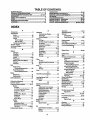
TABLE OF CONTENTS
SAFETY RULES ............................................................ 2
PRODUCT SPECIFICATIONS ...................................... 3
CUSTOMER RESPONSIBIUTIES ..................... 3, 14.17
WARRANTY ..................................................................
3
TABLE OF CONTENTS ................................................ 4
INDEX ............................................................................
4
TRACTOR ACCESSORIES .......................................... 5
ASSEMBLY ................................................................
7-9
OPERATION .......................................................... 10-13
MAINTENANCE SCHEDULE ...................................... 14
SERVICE AND ADJUSTMENTS ............................ 18-23
STORAGE ................................................................... 24
TROUBLESHOOTING ........................................... 25-26
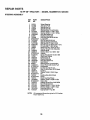
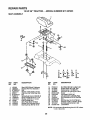
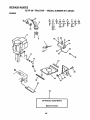
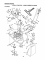
REPAIR PARTS - TRACTOR ................................ 28-43
REPAIR PARTS - ENGINE .................................... 44-48
PARTS ORDERING/SERVICE .................. BACK PAGE
INDEX
A
Accessories
............................................
5
Adjustments:
Brake..........................................20
Carburetor...................................23
Mower
Front-To-Back........................19
Side-To_Slde..........................19
ThrottleControlCable .................23
Air Filter,Engine................................17
AirScreen,Engine.............................t7
Assembly..........................................7-9
B
Battery:
Charging.......................................8
Cleaning......................................16
tnstaJlatton
.....................................9
Levels......................................8,16
Preparation...................................8
StartingwithWeak Battery..........21
Storage.......................................24
Term{na_s
....................................16
Belt:
MotionDrive
Removal/Replacement
...........20
MowerBladeDrive
Rein'oval/Replacement
...........20
Blade:
Sharpening ..................................t5
Replacement...............................15
BrakeAdjustment...............................20
C
CarburetorAdjustment
.......................24
Controls,Tractor ................................10
CustomerResponsibilities
.............15-17
Engine:
Air Filter ..................................17
Air FilterFoam Pre-Cleaner.... ! 7
Air Screen,Engine.................. 17
Battery....................................16
CoolingFins,Engine...............17
EngineOil ...............................16
Fuel Filter................................17
SparkPlugs.............................17
Tractor:.
Blade.......................................15
Lubrication Chart.....................14
MaintenanceSchedule............ 14
Tire Care .........................8,15,21
CuttingHeight,Mower.........................11
E
Electrical:
Interlocksand Relays...................22
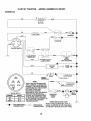
Schematic...................................27
WiringDiagram...........................28
Engine:
AirFilter ......................................17
Air FilterFoamPre.Cleaner........17
Air Screen...................................17
CoolingFins,Engine...................17
Oil Change..................................16
Oil Level.................................12,16
OilType ......................................16
Preparation.................................12
RepairParts...........................44-48
Starting........................................13
Storage.......................................24
F
Filter:
Air Filter ......................................17
AirFilterFoamPre-Cleaner........ 17
Fuel.............................................17
Fuel:
Type ............................................12
Storage.......................................24
Fuse ...................................................22
H
HoodRemova!/Installation
.................22
L
LevelingMowerDeck.........................19
Lubrication:
Chart...........................................14
M
MaintenanceSchedule.......................14
Mower:.
Adjustment,Front-to-Back.......... 19
Adjustment,Side-to-Side............ 19
BladeSharpening.......................15
BladeReplacement.....................15
CuttingHeight..............................11
installation....................................18
Operation....................................12
Removal......................................18
MewingTips .......................................13
Muffler................................................17
SparkArrester..........................3,38
O
Oil:
Operation..............................
10-13
OperatingMower................................12
Options:
Accessories..........................
5
SparkArrester..........................3,38
P
ParkingBrake ...............................10-11
PartsBag .............................................6
Parts,Replacement/Repair...........28-43
ProductSpecifications
...........................3
R
RepairParts..................................28-48
S
SafetyRules.........................................2
Seat ..................................................... 8
Serviceand Adjustments..............t8-23
Carburetor...................................23
Fuse .............................................
22
HoodRemoval/Installation
..........22
MotionDriveBelt
Removal/Replacement
...........20
MowerBladeDriveBelt
Removal/Replacement
...........20
Mowar Adjustment
Front-to-Back........................19
Side to-Side ...........................19
MowerRemoval..........................18
"TireCare .............................8.15,21
SlopeGuideSheet.............................51
SparkPlugs.............................
17
Specifications.......................................3
Startingthe Engine ........................12-13
SteeringWheel................................7,21
StoppingtheTractor...........................11
Storage..............................................24
T
ThroffieControlCable
Adjustment..................................2.3
Tires...................................................
8,15.21
TroubleBhootingChart..................25-26
Transaxle:
Repair Parts...........................42-4.3
W
Warranty..............................................3
WiringDiagram..................................28
WiringSchematic...............................28
Cold WeatherConditions.......12.16
Engine.........................................16
Storage.......................................
24
4
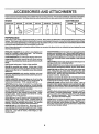
ACCESSORIES
AND ATTACHMENTS
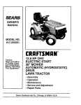
Thoseaccessoriesand attachmentswereavailablewhentheunitwaspurchased.They are alsoavailableat mostSears retailoutlets,
catalogand servicecenters. MostSearsstorescanorderthoseitemsforyouwhenyou providethemodel numberofyourtractor.
ENGINE
SP K PLua
MAINTENANCE
MUFFLER
AIR FILTER
GASCAN
........
F.N iNE
O,L
STABILIZER
BLADES
BELTS
PERFORMANCE
Searsoffersa wide varietyof attachmentsthat fit yourvehicle. Manyoftheseare listed below withbrief explanations of howtheycan
helpyou.Thisllstwascurrentatthetimeofpublloation;
hov_evar,
itmaychangetnfutumyearsmoreattachmentsmaybeadded,changas
may be made In theseattachments, or somemay no longer beavailableor fit yourmodeL Contact your nearest Sears store for the
accessories and attachments that are available for your unit,
Mostof theseattachments do notrequireadditionalhitchesor conversionkits(thosethatdo are indicated)and are designedforeasy
attaching and detaching.
PERMANEX BAGGER lets you collect grassclippingsand
leaves for a healthier,neater looking lawn. Two Permanex
containershold30-galtonplasticbags.
LAWN SWEEPERS let youcollectgrassclippings
and leaves.
LAWN VACS for powerfulcollectionof heavygrassclippings
and leaves. Wandattachmenttoplokup debrtsinhard4o_reash
places,
CARTS make haulingeasy. Varietyofsizesavailable.
ROLLER for smootherlawn surface. 36-inchwide, 18-inch
diameterwater-ttghtdrum
hotdsupto390 Ibs_ofweighLRounded
edgespreventharm to turf. Adjustablescraperautomatically
cleansdrum.
SPREADER/SEEDERS
make seeding, fertilizing, and weed
kBlingeasy, Broadcast spreaders are also useflJtforgranular deIcers and sand,
CORING AERATOR takes small plugsout of sot! to allow
moistureand nutrientstoreachgrass roots_36-1nchswath. 24
hardenedsteelcoringtips. 150 tb. capacityweighttray.
AERATOR promotesdeep root growthfor a healthy lawn,
Tapered 2_5-tnchsteel spikesmountedon 104nch diameter
dtscspunctureholesinsoilatcloseintervalstoletmoisturesoak
in. Steelweighttrayfor increasedpenetration.
MULCH RAKE/DETHATCHER loosenssoiland flipsthatch
and matted leavesto lawn surfacefor easy pickup. Twenty
springtins teeth_ Usefulto preparebare areas for seeding°
Availableforfrontor rear mounting.
SPRAYERSuse 12weltDC electricmotorthatconnectsto the
tractorbattery or other 12-vottsource° Includesboomsfor
automaticsprayingwhen purling,and handheldwandfor spot
spraying. Wand has adjustable spray pattern_For applying
herbicides,insecticides,fungicides,and liquidfedilizers_
SNOW BLADE for snowremovalonly. 14-inchhigh,42-inch
widebladeclears38-Inchpathwhenangled leftorright.Raises,
lowerswithsidelever,Adjustableskids;replaceable,reversible
scraperbar° (Use with tire chains, wheel weights,or rear
drawbarweight.)
SNOWTHROWERhas40-inchswath.Drum.typeaugerhandles
powderyand wet/heavy snow. Mountseasily withsimplepin
arrangement°Dischargechuteadjustsfrom tractor seat.6-inch
diameterspoutdischargessnow10 to 50 feet. LiftcontroUed
at
tractor seal (Usewithchains,wheel weights,or reardrawbar
weight,)
TIRE CHAINSare heavyduty;closelyspacedextra-largecross
linksgivesmoothride,outstandingtraction.
WHEEL WEIGHTSfor rear wheelsprovideneededtraction for
snowremovalordozingheavymaterials. In pairs.(30Ibs_each.)
TRACTOR CAB hasheavydutyvinylfabric over tubularsteel
frame, ABS plastictop; clear plasticwindshieldoffers 360
degreevisibility.
Hingedmetal doorswithcatch. Keepsoperator
warmand dry. Removevinyland wtndshietdsfor useas sun
protectorin summer, (Catalogonly.)
Optional accessories for tractor cab: tinted/temperedsoled
safetyglasswindshield
withhandoperatedwiper;12-voltamber
cautionlightformounting on cabtop. (Catalogonty.)
TRACTOR COVER protectstractor from weather. Made of
Evolution3 fabric(water-repeUent,
extremelybreathable,light
weight,soft,non.abrasive,pliabtein all temperatures,durable,
staln/tear/puncture
resistant,willnot shrinkorstretch.)(Catalog
only,)
TILIJ'R
cultivates
andprepares
solllnone
operatlon_
UsesFro
fromtractor; 12 counter-rotatingblades_ Breaks groundwith
upper-cut action, then deflectsand rattlesit Into a soft,aerated
soil, Chain*drivetransmission.Tills 21-inch path, 6-inchas
deep. (Usechainsand wheelweights.)
I'ILLER has 5 hp engine and 36-inchswathto prepare seed
beds,cultivate,and compost gardenresidue.Tillerhasits own
built.in liftand depthcontrol systemand does NOT requirea
sleevehitch,.Fitsanylawn,yard,or gardentractor. Simplyt_ok
up to the tractor drawbarand got
iiiiiii1,,,
I
................................
ii/!1 ....
ii
I1'111111"1'
i,,
i,i
I
IIII
'1
I
LI]II!
CONTENTS OF HARDWARE PACK
,HWI'II'
'=
III1' I
................................................................
..........
iii1,11,
ii
Parts Bag contents
i,i
shown full size
.....
ii I
,
..
ill
,1[
Parts packed separately
iiii1!
,
ii
,, !,
©
L'IJ Jl
In carton
I,LI
Seat
'\\\/#10.16
Battery acid
x 1_/2
(1) Locknut 3/8-24
(1) 2-3/8" Dia. Washer
Steering
Wheel
Battery
Steering
Tube
(1) Hex Bolt 1/2-13 x 1
(1) Shoulder I_olt 5/16-t8
Owner's Manual
........................
_
Parts bag contents
(1) Lock Washer 1/2
........
•
J'__
Steering Wheel
Adapter
Parts Bag
,,
,11
iiii
1,1,1,
i
i'
not shown full size
I(_
Wheel
Steering
Insert
1
(1) Washer 17/32 x 1-3/16 x 12 Gauge
<_(2)
Keys
Steering
Bushing
%
•
,,ll
(2) Hex Nuts 1/4-20
,.HL
......
(2) Lock Washers
(2) Washers 9/32 x 5/8 x 16 Gauge
I
I
1/4
15 ° Slope Sheet
Battery Caps
and Instructions
,
L,,,,...............
LY
............ r
'"'""
................
:
"Your new iract0r has been assembled at the factory with exception of those parts left unassembled for shipping purposes.
To ensure safe and proper operation of your tractor, all parts and hardware you assemble must be tlghtened securely. Use
the correct tools as necessary to insure their propertightness.
TOOLS REQUIRED
FOR ASSEMBLY
Asocket wrench set witl make assembly easier. Standard
wrench sizes are listed.
(1) 5/16" wrench
(2) 7/16" wrenches
(1) 1/2" wrench
(1) 9/16" wrench
(1) 3/4" wrench
Screwdriver
Tire pressure gauge
Utility knife
When right and left hand ts mentioned in this manual, it
means when you are In the operating position (seated
behindthe steering wheel).
STEERING
NHEEL
ADAPTER
STEERING
BOOT
TO REMOVE UNIT FROM CARTON
UNPACK
•
•
•
STEERING
BUSHING
CARTON
Remove all accessible loose parts and parts cartons
from carton (See page 6).
Cut along dotted lines on carton, from top to bottom, all
four comers of carton and lay panels flat.
Check for any additional loose parts or cartons and
remove.
BEFORE ROLLING UNIT OFF SKID
ATTACH
•
•
STEERING
WHEEL
(See Fig. 1)
•
•
Position steering boot over steedng shaft.
Place tabs of steering bootover slots in dash and push
down to secure.
•
•
Slidesteertng wheeladapteronto upper steering shaft.
Positionfront wheels of the tractorso they are pointing
straightforward.
Position steering wheel so cross bars are horizontal
(left to right) and slide onto adapter.
•
•
,
STEERING SHAFT
$oHIPPING
Slide the steering bushing over the steering shaft.
Raise steering shaft forward untilscrew holes in dash
line up with steering bushing. Install two (2) sheet
metal screws and tighten securely.
FIG. 1
Assemble large flatwasher and 3/8-24 hex locknutand
tighten securely.
Snap insert into center of steering wheel.
•
Remove protective plasticfrom tractor hood and grill.
IMPORTANT: CHECK FOR AND REMOVE ANY
STAPLES IN SKID THAT MAY PUNCTURETtR ES WHERE
UNIT tS TO ROLL OFF SKID.
(See Fig. 6)
•
Raise attachment liftlever to its highest position.
•
Release parking brake by depressing clutch/brake
pedal.
,
•
Place gearshift lever in "NEUTRAL" position.
Roll unit backwards off skid°
°
Remove banding holdingdischarge guard up against
tractor.
snlON)
STEERING SHAFT
(ASSEMBLY POSITION)
7
HOW TO SET UP YOUR TRACTOR
PREPARE
I
II
I
I
,
BATTERY
ii
INSTALL SEAT (See Fig. 3)
Adjust seat before tightening adjustment bolt.
•
Remove cardboard packing on seat pan,
(See Fig. 2)
,
i,ii,i,1,ii,ii,iiiii,iiii,ii,iiii,
I,
III,
,
L !LLLIJLI
CAUTION: Wear eye and face shield.
Wash hands or clothing immediately If
accidentally In contactwlth batteryacid.
Do not acid
smoke,
Fumes from charged
battery
are explosive,
Read the lnstrucUons Included with the
battery vent caps. Always wear gloves,
clothing and goggles to protect your
hands, skin and eyes,
•
•
Place seat on pan and assemble shoulder bolt.
Assemble adjustment bolt, lockwasher and flatwasher
loosely. Do notttghten.
•
Tighten shoulder bolt securely.
•
•
•
Lower seat into operating position and sit on seat.
Slide seat untila comfortableposition isreached which
allows you to pressclutch/brake pedal all the way down
(See Fig. 6).
Get off seat without moving its adjusted position.
•
Raise seat and tighten adjustment bolt securely.
Your unit has a battery chargtngsystem whtch ts sufficient
for normal use, However, periodic charging of the battery
with an automotive charger will extend its life.
•
See instructionspacked with vent caps in parts bag.
•
Fill battery with acldo Fill each cell until it reaches the
bottom of the vent wells. Do not overfill.
•
Allow battery to stand and settle for at least thirty
minutes. After standing, check the level of actd. tf
below the vent wells, add more acid until the correct
level Is reached.
SEAT
S_TP_
SHOULDER
BOLT
!
While batteryts standing (after addlng acid) and later, while
battery is being charged, continue with assembly of unit,
iMPORTANT:
TO MAXIMIZE THE LIFE OF YOUR
BATTERY, IT IS NECESSARY THAT THE BATTERY BE
CHARGED BEFORE USE° FAILURE TO CHARGE
BATTERY CAN RESULT IN A SHORTENED BATTERY
LIFE.
•
FLAT WASHER
ADJUSTMENT
Charge battery at a rate of 6 amperes for t hour. Use
a 12volt batterycharger, Observe all safety precautions
required for battery charging.
.
Check the acid level after the battery ts charged, if the
acid has fallen below the correct level, add distilled or
Iron free water,
.
Install the vent caps to cover the vent wells. Wash the
top of the battery with water to remove any acid, then
wipe dry.
.
Check battery case for leakage to make sure that no
damage has occurred in handling_
•
Dispose of excess battery acid. Neutralize acid for
disposal by adding it to four inches of water in a five
gallon plastic container. Stir with a wooden or plastic
paddle while adding baking soda until the addition of
more soda causes no more foaming.
•
Follow instructionson how to install battery.
CUT AWAY VIEW
!
I
_
_
jVEWr
FIG. 3
CHECK
TIRE
PRESSURE
The tires on your unit were overinflated at the factory for
shipping purposes. Correct tire pressure Is important for
best cutting performance.
•
Reduce tire pressure to PSI shown In "PRODUCT
SPECIFICATIONS" on page 3 of this manual.
CHECK
DECK
LEVELNESS
For bestcutting.:esults,mower housing should be propedy
leveled. See TO LEVEL MOWER HOUSING" in the
Service and Adjustments section of this manual.
CHECK
BELTS
FOR
PROPER
POSITION
OF ALL
See the figures that are shown for replacing motion and
mower blade drive belts In the Service and Adjustments
section of this manual. Verify that the belts are routed
correctly.
CAP
_ .........
_
CHECK
BATTERY
CELL ACID
_VEL
FIG. 2
LOCK WASHER
BOLT
8
BRAKE
SYSTEM
After you learn how to operate your tractor, check to see
that the brake is properly adjusted, See "TO ADJUST
BRAKE" in the Service and Adjustments section of this
manual.
ASS
SLY
iNSTALL BATTERY (See Figs, 4 & 5)
CAUTION: Do not short batten=/terminals, Before Installing battery, remove
metal bracelets, wristwatch bands,
rings, etc.
Positive terminal must be connected
first to prevent sparking from accldentat grounding.
Lift seat to raised position_
Open battery box door.
,
,
Lower battery into battery box with battery terminals
toward front of unit.
,
•
Be sure battery drain tube is attached to battery box°
First connect RED batter_jcable to positive (+) battery
terminalwith hex bolt, flat washer, Iockwasher and hex
nut as shown. Tighten securely.
Connect BLACK grounding cable to negative (-) battery terminal with remaining hex bolt, flat washer, lock
washer and hex nut. Tighten securely.
Close battery box door.
°
•
BATTERY
VENT CAPS
FIG. 5
Open battery box door for:
,
inspection for secure connections (to tighten hardware).
•
Inspection for corrosion.
•
Testing battery.
•
°
Jumping (if required)°
Periodic charging.
,/'CHECKLIST
BEFORE YOU OPERATE AND ENJOY YOUR NEW
TRACTOR, WEW/SH TO ASSURE THATYOU RECEIVE
THE BEST PERFORMANCE AND SAT/SFACTION FROM
THIS QUALITY PRODUCT.
PLEASE REVIEW THE FOLLOWING CHECKLIST:
BATTERY
BOX DOOR
_/
All assembly instructions have been completed.
,/
No remaining loose parts in carton.
/
Battery isproperly prepared and charged. (Minimum
1 hour at 6amps).
4" Seat is adjusted comfortably and tightened securely.
POSITIVE
_IEGATIVE
(RED) CAB_
(BLACK) CABLE
#'
All tires are properly inflated. (For shipping purposes,
the tires were over-inflated at the factory).
v"
Be sure mower deck is properly leveled side-to-side/
front-to.rear for best cutting results. (Tires must be
properly inflated for leveling).
#" Check mower and drive belts. Be sure they are muted
properly around pulleys and inside all belt keepers.
4" Check wiring. See that all connections are stillsecure
and wires are properly clamped.
WHILE LEARNING HOWTO USE YOUR TRACTOR, PAY
EXTRA A TTENTION TO THE FOLLOWING IMPORTANT
ITEMS:
FLAT
WASHER
v"
#"
Engine oil is at proper level.
Fuel tank is filled with fresh, clean, regular unleaded
gasoline.
€" Become familiar with all controls - their location and
function. Operate them before you start the engine.
POSITIVE (+) TERMINAL
NEGATIVE (.) "tERMINAL
4"
FIG. 4
9
Be sure brake system is in safe operating condition.
i
....
iiiii1,,i
...........
_ ii ,i ii iii , ii
ii1,111,111111111
i I i i
i, ,11,
II'H
:
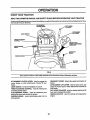
KNOW YOUR TRACTOR
READ THIS OWNER'S
MANUAL
AND SAFETY
RULES
BEFORE
OPERATING
YOUR
TRACTOR
Comparethe,tustrations with your tractortofamiltadze yourselfwith the locations ofvarious controlsand adjustments. Save
this manual for future reference,
ATTACHMENT
CLUTCH LEVER
LIFT LEVER
PLUNGER
ATTACHMENT
UFT LEVER
UGHT SWITCH
THROTTLEJCHOKE
CONTROL
MOWER DECK
HEIGHT ADJUSTMENT
POSITIONS
CLUTCH/BRAKE
PEDAL
GEARSHIFT
LEVER
PARKING BRAF,E
IGNmON
SWITCH
)
FIG. 6
Sears tractors conform to the safety standards of the American National Standards Institute,
GEARSHIFT LEVER: Selects the speed and direction of
tractor,
ATTACHMENT LIFT LEVER: Used to raise, lower, and
adjust the mower deck or other attachments mounted to
your tractor=
LIFT LEVER PLUNGER: Used to release attachment lift
lever when changing its position.
IGNITION SWITCH: Used for starting and stopping the
engine.
ATTACHMENT CLUTCH LEVER: Used to engage the
mower blades, or other attachments mounted to your
tractor,
LIGHT SWITCH: Turns the headlights on and off,
THROTTLE/CHOKE CONTROL: Used for starting and
controllingengine speed,
CLUTCH/BRAKE PEDAL:
Used for declutching and
braking the tractorand starting the engine,
PARKING BRAKE: Locks clutch/brake pedal into the
brake position.
10
The operation of any tractor can result in foreign objects thrown into the eyes, which can
result in severe eye damage, Always wear safety glasses or eye shields while operating
your tractor or performing any adjustments or repairs. We recommend wide vision safety
mask for over the spectacles or standard safety glasses, available at Sears Retail or
Catalog stores.
HOW TO USE YOUR TRACTOR
TO SET PARKING
BRAKE
•
Depress clutch/brake pedal intofult "BRAKE" position
and hold,
-
Place parking brakelever tn"ENGAGED" positionand
releasepressurefrom clutch/brakepedal, Pedal should
rematn|n"BRAKE"posttion, Make sure parkingbrake
will hold vehicle secure.
ATTACHMENT
CLUTCH LEVER
"ENGAGED =
POSITION
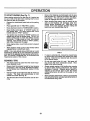
NOTE: Under certain conditionswhen unit isstanding idle
with the engine Panning,hot engine exhaust gases may
cause "browning" of grass., To eliminate this possibility,
always stop eng=newnen stopping unit on grass areas.
(See Fig. 7)
i
,J_,..,:L
.......
!
Always operate engine at full throttle.
\_-\._
•
BRAKEPARKING
"ENGAGED"
POSITION
o
Operating en_]ineat less than full throttle reduces the
battery charging rate.
Full throttle ofters the best bagging and mower performance,
TO MOVE FORWARD AND BACKWARD (See
Fig. 6)
LEVER
The directionand speed of movement is controlled by the
gearshift lever.
,
Start tractor with clutch/brake pedal depressed and
gearshift lever in "NEUTRAL" position.
IGNITION
KEY
"BRAKE =
POSITION
CLUTCH]BRAKE
PEDAL =DRIVE"
POSITION
\
•
Move attachment clutchlever to "DISENGAGED" position,
GROUND DRIVE Move gearshift lever to "NEUTRAL" positlon_
BRtNGTRACTORTOACOMPLETE
STOP
MOWER
CUTTING
HEIGHT
(See
•
Grasp lift lever.
•
Press plunger with thumb and move lever to desired
position.
The cuffing height range is approximately 1-1/2 to 4". The
heights are measured from the ground to the blade tip with
the engine not n,nning. These heights are approx=mate
and may vary depending upon soil conditions, height of
grass and types of grass being mowed.
• The average lawn should be cut approximately 2-1/2
!nches during the coolseason and over3 inchesduring
hot months. For healthier and better Iooklng lawns,
mow often and after moderate growth.
•
For best cutting performance, grass over 6 Inches in
height should be mowed twice, Make the first cut
relatively high; the second to desired height,
-
Move throttle controlto "SLOW" position°
NOTE: Failureto movethrottle controlto"SLOW" position
and allowing engine to idle before stopping may cause
engine to "backfire".
•
Turn ignitionkey to "OFF" position and remove key,
Always remove key when leaving vehicle to prevent
unauthorized use°
Never use choke to stop engine.
Slowly release clutch/brake pedal to start movement.
The position of the attachment lift lever determines the
cutting height.
MOWER BLADES -
Depress clutch!brakepedal Into fuIi"BRAKE" posltlon_
•
TO ADJUST
Fig, 6)
STOPPING (See Fig. 7)
•
Move gearshift lever to desired position.
BEFORE SHIFTING OR CHANGING GEARS. FAILURE
TO DO SO WILL SHORTEN THE USEFUL LIFE OF YOUR
TRANSAXLE.
PARKING BRAKE
"DISENGAGED"
POSITION
•
•
IMPORTANT;
FIG. 7
•
, i ......
TO USE THROTTLE CONTROL (See Fig. 7)
"DISENGAGED"
POSITION
THROTTLE/
CHOKE
•
i
as aescrlbea above, before leaving the
operator's
position; to empty grass
CAUTION: A.lwpysstopunltcompletely,
................. ca,tcher, ate,
GEARSHIFT
ENGINE
i
11
OPERATION
TO OPERATE
MOWER
(See Fig. 8)
Your unit is equipped with an operator presence sensing
switch. Any attempt by the operatorto leave the seat with
the eng!ne runningand the attachment clutch engaged will
shut off the engine.
•
Select desired height of cut.
•
Engage mower by slowly moving attachment clutch
lever to "ENGAGED" position_
TO STOP MOWER- Move attachment clutchlever to
"DISENGAGED" positton_
•
•
If stopping Is absolutely necessary, push clutch/brake
pedal quickly to brake position and engage parking
brake.
•
Move gearshift lever to 1st gear and be sure you have
allowed room for tractor to roll slightly as you restart
movement.
To restartmovement, slowly release parking brake and
clutch/brake pedal.
°
TO TRANSPORT
CAUTION: Do not operate the mower
without either the entire grass catcher,
on mowers so equipped, or the discharge guard In place.
•
Raise attachment rift control to highest position.
•
When pushing or towing your unit, be sure gearshift
lever is tn "NEUTRAL" position.
Do not push or tow unit at more than five (5) MPH.
•
ATTACHMENT CLUTCH LEVER
"DISENGAG _n. PosmoN
"ENGAGED"
POSITION
Make all turns slowly.
ATTACHMENT
LIFT LEVER
HIGH POSITION
BEFORE STARTING THE ENGINE
CHECK
LOW
POSITION
ENGINE
OIL LEVEL
(See
Fig. 13)
-
The engine In your unit has been shipped, from the
factory, already filled with summer weight oil
°
Check engine oil with unit on level ground.
•
Remove oil fill dipstick and wipe clean, replace and
screw cap tight, wait for a few seconds, remove and
read 011level If necessary, add oil until "FULL" mark
on dipstick ls reached. Do not overfill.
•
For cold weather operation you should change oil for
easier starting (see "OIL VISCOSITY CHART" In the
Customer Responsibilities section of this manual).
•
To changeenglneoil, see the Customer ResponstbUities
section in this manual.
ADD
GASOLINE
•
Fill fuel tank. Use fresh, clean, regular unleaded
gasoline. (Use of leaded gasoline willincrease carbon
and lead oxide deposits and reduce valve life).
IMPORTANT; WHEN OPERATING IN TEMPERATURES
BELOW32°F(0°C), USE FRESH, CLEAN WINTER GRADE
GASOLINE TO HELP INSURE GOOD COLD WEATHER
STARTING.
R_HI
RUNNER
WARNING: Experience Indicates that alcohol blended
fuels (called gasohol or using ethanol or methanol) can
attractmoisture which leads to separation and formation of
acids during storage. Acidic gas can damage the fuel
system of an engine while In storage. To avoid engine
problems, the fuel system should be emptied before storage of 30 days or longer. Drain the gas tank, start the
engine and let it run until the fuel lines and carburetor are
empty. Use fresh fuel next season. See Storage Instructions for additional Information. Never use engine or
carburetor cleaner products in the fuel tank or permanent
damage may occur.
DISCHARGE GUARD
FIG. 8
TO OPERATE ON HILLS
L
o
&
-_
CAUTION: Do not drive up or down
o
hills wlth slopes greater than 15 and
................................................
i Ill I
do not drive across i any slope.
II Ill
CAUTION: Fill to bottom of gas tank
filler neck. Do not overfill. Wipe off any
spilled oli or fuel. Do not store, spill or
use gasoline near an open flame,
Choose the slowest speed before starting up or down
hills_
•&.voidstopping or changing speed on hills.
if slowing is necessary, move throttle control lever to
slower position.
12
OPERATnO
°
TO START ENGINE (See Fig. 7)
When starting engine for the first time or if engine has
run out of fuel, it will take extra cranking time to move
fuel from the tank to the engine.
•
Depress the clutch!brake pedal and set the parking
brake.
•
Place gearshift lever in "NEUTRAL" position_
o
•
Move attachment clutchto "DISENGAGED" position.
Move throttle controllever to "CHOKE" position for
cold engine start. For warm engine start, move
throttle control to "FAST" position.
attempts, move h o
on o to FAS
wait a few minutes and try again.
•
pos""on,
°
When engine starts, move throttle control to desired
position.
°
Allow engine to warm up for a few minutes before
engaging drive or attachment clutch.
NOTE: tf at a high altitude (above 3000 feet) or in cold
temperatures (below 320 F), the carburetor fuel mixture
may need to be adjusted for best engine performance.
See "TO ADJUST CARBURETOR" in the Service and
Adjustments section of this manual
MOWING
°
•
,
•
Drive so that clippings are discharged onto the area
that has been cut. Have the cut area to the right of
the machine. This will result in a more even distribution of clippings and more uniform cutting.
When mowing large areas, start by turning to the
right so that clippings will discharge away from
shrubs, fences, driveways, etc. After one or two
rounds, mow in the opposite direction making left
hand turns until finished(See Fig. 9).
FIG. g
TIPS
Tire chains cannot be used when the mower housing is attached to unit.
Mower should be properly leveled for best mowing
performance. See "TO LEVEL MOWER HOUSING"
m the Service and Adjustments section of this
manual.
Use the runner on the right hand side of mower as
a guide, The blade cuts approximately an inch
outside the runner (See Fig,8),
The left hand side of mower should be used for trimming,
13
°
if grass is extremely tall, it should be mowed twice
to reduce load and possible fire hazard from dried
clippings. Make first cut relatively high; the second
to the desired height.
°
Do not mow grass when it is wet. Wet grass will
plug mower and leave undesirable clumps. Allow
grass to dry before mowing.
•
/_ways operate engine at full throttle when.mowing
to assure better mowing penormance ana proper
discharge of material. Regulate ground speed by
selecting a low enough gear to give the mower
cutting performance as welt as the quality of cut
desired.
,
When operating attachments, select a ground speed
that wilt suit the terrain and give best performance of
the attachment being used.
RESPONSIBILITIES
ASYOU
COMPLETE
REGULARSERVICE
..................
_, _€
_
/_/_/_.,_ERVICE
DATES
III1'11'11
I'
CheckBrakeOperation
Ii# #
!k/
C,eck',roP.e=ura
IV
v'
" +. " " "
T Checker
_0SeFasteners
R
Sha_ervl:leplace MowerBlades
tj_4
c m+<8o.;_
L,;vom_h;;_o
0
Clean Batteryand Terminals
R
Check Transmission Cooling
.....
,_djUS,
Stad_,,olti;+)
Tens,on .
--
V' ......
_
_,_V',,
+
Adjust Motion Drive Belt(s) Tension
......
I_s
CheckEngineO11
Level
ChangeEngineOII
If
_
l/
Ctean
Airmite,
:_21_ i
,,
'"
:1/
V'_I
NE Clean Air Screen.......................
__
IkIP21....................
G I Inspect Muffler/Spaf_An'ester
I_l
Replace Oil Filter (if equipped)
Clean
E.glne
Cooling
Ftns
.
!_,2
!V'_!
E '"Replace
Sp_kPing ..............
._,.,
!V" 1I/
ReplaceAir FilterPaperCartridge................
ReplaceFuel Fitter
'
_#+
1 - Change more often when operating under s heavy load or In high ambient temperatures+
2 - Service mote often when operating In dirty or dusty conditJons_
3 + ff equipped with oil fl_tet, change oll every 60 houri+
4 - Repine blades more often when mowing in aandy aoiL
6 - if equipped with adjustable system+
LUBRICATION
GENERAL RECOMMENDATIONS
(_)SPINDLE
The warranty on thisvehicle does not coveritems that have
been subjected to operator abuse or negligence. To
receive full value from the warranty, operator must maintain unit as instructedin this manual.
ZERK_I
(If equipped)
_..__.-..._._
_Jl[
.....
(_) FRONT WHEEL'"I_='r'_N:
BEARING ZERK _
|
Some adjustments wilt need to be made periodically to
properly maintain your unit+
CHART
F----'SPINDLIE
_
_._t
__
ZERK (_)
(If equlppsd)
_ FRONT WHEEL (_)
BEARING _RK
|
All adjustments in the Service and Adjustments sectionof
this manual shouldbe checked at leastonce each season+
,
®
Once a year you should replace the spark plug, clean
or replace air filter, and check blades and belts for
wear. A new spark plug and clean air filter assure
proper air-fuel mixture an_ help yourengine runbetter
andlast longer.
BEFORE
EACH
®
CLUTCH
PIVOT(S)
USE
•
Check engine oil level.
•
Check brake operation.
•
•
Check tire pressure.
Check for loose fasteners.
PWOTS
d)
(_) SAE 30 OR 10W30 MOTOR OIL API - SG
_GENERAL
(_)REFER
14
PURPOSE GREASE
TO CUSTOMER
RESPONSIBILITIES
=ENGINE" SECTION
IMPORTANT:
DO NOT OIL OR GREASE THE PIVOT POINTS
WHICH HAVE SPECIAL NYLON BEARINGS,
VISCOUS LUBRICANTS WtLL ATTRACT DUST AND DIRT THAT WILL SHORTEN
THE LIFE OF "tHE SELF-LUBRICATING
BEARINGS,
IF YOU
FEEL THEY MUST BE LUBRICATED,
USE ONLY A DRY, POWDERED GRAPHITE TYPE LUBRICANT SPARINGLY.
CUSTO
E
TIES
TRACTOR
AZways observe safety rules when performingany matnten_ce,
BRAKE
OPERATION
If unit requires more than six (6) feet stopptngdistance at
high s_eed in highest gear, than brake mustbe adjusted.
(See 'TO ADJUST BRAKE" in Service and Adjustments
section of this manual).
"t
TIRES
,
.
-
Maintain proper air pressure In all tires (See "PRODUCT SPECIFICATIONS" on page 3 of this manual),
Keeptires free of gasoline, oil, or insect control chemi.
cais which can harm rubber.
222
Avoid stumps, stones, deep ruts, sharp objects and
other hazards that may cause tire damage.
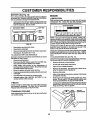
BLADE
NED( BOLT (GRADE 81"
*A GRADE 8 HEAT TREATED BOLT CAN BE
IDENTIFIED BY SIX UNES ON THE BOLT HEAD.
CARE
For best results mower blades must be kept sharp_ The
blades can be sharpened with a file or on agrinding wheel.
We suggest they be sharpened or replaced after every 25
hours of mowing. Check blades more often if mowing in
sandy conditions.
,
Do not attempt to sharpen blades while they are on the
mower,
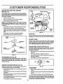
TO SHARPEN BLADE (See Fig. 11)
-
.
The blade can be sharpened with a file or on a grinding
wheel. Do not attemptto sharpen while on the mower.
•
To check blade balance, you will need a 5/8" diameter
steel bolt, pin. or a cone batancer. (When using a cone
balancer, follow the instructions supplied with balancer),
FIG, 10
Care should be taken to keep the blade balanced. An
unbalanced bladewill cause excessive vibration and eventual damage to mower and engine.
Replace bent or damaged blades.
BLADE REMOVAL
(See Fig. 10)
•
Raise mower to highest position to allow access to
blades_
=
Removehexbolt, lockwasherandflatwashersecuring
blade.
•
install new or resharpened blade with trailing edge up
towards deck as shown.
.
Reassemble hex bolt, lock washer and fiat washer in
exact order as shown.
•
Slide blade onto an unthreaded portion ofthe steel bolt
or pin and hold the bolt or pin parallel with the ground.
If blade Is balanced, it should remain In a horizontal
position, tf either end of the blade moves downward,
sharpen the heavy end until the blade is balanced.
NOTE: Do not use a nail for balancing blade. The lobes of
the center hole may appear to be centered, but are not,
Tighten bolt securely (30-35 Ft. Lbs. torque).
IMPORTANT: BLADE BOLT IS GRADE 8 HEATTREATED.
11
BLADE
5/8" BOLT
OR PIN
FIG. 11
15
CUSTOMER RESPONSIBILITIES
BATTERY
(See Fig. 12)
Your unit has a battery charging system whlchis sufficient
for normal use° However. periodic cnargmg of.the battery
with an automotive charger will extend it's life.
•
Acid solution level In each battery cel!should be even
with bottoms of vent walls. Add onlydistilledor ironfree
water if necessary. Do not overfill.
CUT AWAY VIEW
/
!
r
ENGINE
LUBRICATION
Only use high quality detergent oll rated with API service
classification SG. Select the oil's SAE viscosity grade
according to your expected operating temperature.
SAE%qscosn%,
GRAOES
VENTCAP
4IBm
WELL
! !:1
I:'JI l_
_ I _
_1 lY
TE,M P_:_ATURE RANGE ANltC_PATI_3 BEFORE NEXT OL CHANGE
NOTE: ARhoughmultt_vtscosttyoils (5W30, 10W30, etc,)
improve starting in coldweather, these multtLvlscosity otis
wlll result in Increased oli consumption when used _ooe
32°C. Check your engine oillevel more frequently to avoid
possible engine damage from running low on oil.
Change the oll after the first two hours of operation and
every 25 hours thereafter or at least once a year if the
tractor is not used for 25 hours in one year.
Check the crankcase oil level before starting the engine
and after each eight (8) hours of continuous use, Tighten
oil fill cap/dipstick securely each time you check the otl
level,
TO CHANGE ENGINE OIL (See Fig. 13)
Determine temperature range expected before ollchange.
All oil must meet API service classification SG,
CELl.ACID
FIG. 12
*
,
,
*
TO
Keep battery and terminals clean.
Keep battery boltstight.
Keepvent capstightand small vent holesin caps open.
Recharge at 6 amperes for 1 hour.
CLEAN BATTERY AND TERMINALS -
Corrosion and dirt on the battery and terminals can cause
the battery to "leak" power°
,
Remove terminal guard.
,
Disconnect BLACK battery cable first then RED battery cable and remove battery from tractor.
, Wash battery with solution of four tablespoons of
baklng sodato onegallon ofwater. Becarefulnottoget
the soda solution into the cells.
,
,
.
,
Rinse the battery with plain water and dry.
Clean terminals and batterycable ends with wire brush
until bright.
Coat terminals with grease or petroleum jelly.
Reinstall battery (See "INSTALL BATTERY" in Assembly section Ofthis manual).
Be sure vehicle Is on level surface.
=
.
Oil will drain more freely when warm.
Catch oil in a suitable container.
o
Remove oil fill dipstick_ Be careful not to allow dirt to
enter the engine when changing oil.
.
•
Remove drain plug.
After oil has drained completaly, replace oll drain plug
and tighten securely.
Refill engine with oil through oil fill dipsticktube. Pour
slowly. Do not overfill. For approximate capacity see
Product Specifications on page 3 of this manual.
*
V-BELTS
Check V-belts for deterioration and wear after 100 hours
and replace if necessary. The belts are not adjustable.
Replace belts if they begin to slipfrom wear.
TRANSAXLE
*
,
Usegaugeonollfilldipstickforchecktnglevel. Besure
dipstickcap istightened securely for accurate reading.
Keep oil at "FULL" line on dipstick.
OIL RLL
CAP/DIPS'riCK
COOLING
Keep transaxie free from build-up of dirt and chaff which
can restrictcooling°
OIL DRAIN PLUG
FIG. 13
16
AIR FILTER
FOAM
PRE-CLEANER
SCREWS
(See Fig. 14)
BLOWER HOUSING
Your engine will not run properly and may be damaged by
using a dirtyair filter. Clean the foam pre-cleaner element
after every 25 hoursof operation, more often if used in very
dusty, dirty conditions.
,
Remove knob and cover.
-
Remove cartridge nut and replace cartridge.
•
Reassemble and tighten securely,
NOTE: Do not attempt to clean or oil the paper cartridge.
Replace paper cartridge once a year or after every 100
hours of operation, more often tf used in very dusty, dirty
conditions,
-
Wash foam pre-cleaner in liquid detergent and water.
.
Wrap foam pre-cleaner in cloth and squeeze dry.
o
Lightly coat foam pre-cleaner with clean engine oil.
Squeeze in towel to remove excess olt. Do not saturate,
•
•
STARTER
HOUSING
OIL FILL
DIPSTICK
SPARK
PLUG
ENGINE COOLING RNS
FIG. 15
Install foam pre-cleaner over paper cartridge.
Reassemble cover and secure with knobs.
MUFFLER
inspectand replace corroded mufflerand spark arrester (if
equipped) as tt could create a fire hazard and/or damage.
SPARK
Replace spark plugs at the beginning of each mowing
season or after every 100 hours of use, whichever comes
first. Sp;Jgtypeark
plu
e and gap setting is shown in "PRODUCT SPECIFICATIONS" on page3 of this manual.
CARTRIDGE
NUT
IN-UNE FUEL FILTER (See Fig. 16)
PAPER
CARTRIDGE
FOAM
PRE.CLEANER
PLUGS
FuelfUtershouldbe replaced once each season. Iffuelfilter
becomes clogged, obstructingfuel flow to carburetor, replacement is required,
•
With engine cool, remove filter and plug fuel line
sections.
AIR CLEANER BASE
FIG. 14
AIR SCREEN
(See Fig. 15)
The engine air screen must be kept free of dirtand chaffto
prevent engine damage from overheating. Clean with a
wire brush or compressed air to remove dirt and stubborn
dried gum fibers.
°
Place new fuel filter in position in fuel line,
°
Be sure there are no fuel line leaks and clamps are
properly positioned.
Immediately wipe up any spilled gasoline.
•
FUEL
FILTER
ENGINE COOLING FINS (See Fig. 15)
FIG. 16
Remove any dust, dirt or oil from engine cooling fins to
prevent engine damage from overheating.
CLEANING
°
Remove oil fill dipstick and cover opening to prevent
entry of dirt.
°
Clean engine, battery, seat, finish, etco of all foreign
matter,
•
Remove screws from blower housing and lift housing
off engine.
Remove the screws securing the starter housing and
lift housing off engine.
°
Keep finished surfaces and wheels free of all gasoline,
oil, etc.
Protect painted surfaces with automotive type wax.
o
•
,
°
We do not recommend using a garden hose to clean your
unit unless the electrical system, muffler, air filter and
carburetor are covered to keep water out÷ Water In engine
can result in a shortened engine life.
Use compressed air or stiff bristle brush to thoroughly
clean engine coolingfins°
To reassemble, reverse above procedure.
17
........
u
i
i
iii
iii
AND ADJUSTM
I
L' ,ll,ll,lml,ll,l,lll,ll,ll,,
i
I i1,1111,1,1111,
i
i
i
i1,,
,i,iil,l,lllllllllllllllll
CAUTION: BEFORE PERFORMING ANY SERVICE OR ADJUSTMENTS:
&.
s
tl
e
Depress clutch/brake pedal fully and set parking brake.
Place gearshift lever In "NEUTRAL" position.
Place attachment clutch in "DISENGAGED" position,
Turn Ignition key "OFF =and remove key.
Make sure the blades and all moving parts have completely stopped,
Disconnect spark plug wire from spark plug and place wire where it cannot come In contact with
plug.
TRACTOR
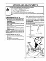
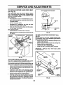
TO REMOVE MOWER
NOTE: The mower ctutchrodhas a trunnionthat has been
preset, atthe factory,for optimum mower performance. DO
NOT MOVETHETRUNNION ONTHE CLUTCH ROD. fffor
any reason the trunnionhas been moved on the clutchrod,
itmust be reset to correct position(parallel with clutchrod)
and measure 10-11/32" (Check dimension on edge of fiat
work surface as shown).
(See Fig. 17)
Mower will be easier to remove from the right side of unit°
•
•
°
Place attachment clutch in "DISENGAGED" position.
Moveattachment liftleverforward tolower mower to its
lowest position.
Roll belt off engine pulley.
Be sure to tighten trunnion nut securely against trunnion
after making any adjustments.
•
Disconnect clutch rod from clutch lever by removing
retainer spring,
° Disconnect suspension arms from rear deck brackets
by removtng retainer springs.
•
Disconnect front links from deck by removing retainer
springs.
•
Raise lift lever to raise suspension arms. Slide mower
out from under tractor.
IMPORTANT:
IFANATTACHMENTOTHERTHANTHE
MOWER IS TO BE MOUNTED TO THE TRACTOR, THE
R.H, AND LH. SUSPENSION ARMS MUST BE REMOVED
FROM TRACTOR,
TO INSTALL
MOWER (See Fig. 17)
•
Raise attachment lift lever to its hEghestposition.
•
Slide mower undertractorwith dischargeguard to right
side of tractor,
•
•
SEE NOTE ABOVE
CLUTCH
ROD
RETAINER
SPRING
Lower lift lever to its lowest position.
Installmower in reverse order of removal Instructions.
RETAINER
SPRINGS
18
FIG. 17
ADJUSTMENTS
........................
TO LEVEL
MOWER
HOUSING
i ::It
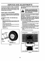
FRONT-TO-BACK ADJUSTMENT (See Figs, 20 and 21) IMPORTANT: DECK MUST BE LEVEL SIDE-TO-SIDE. IF
THE FOLLOWING FRONT-TO-BACK ADJUSTMENT tS
NECESSARY, BESURE TO ADJUST BOTHFRONT LINKS
EQUALLY SO MOWER WILL STAY LEVEL SIDE-TOSIDE,
To obtain the best cutting results, the mower housing
should be adjusted sothat the front isapproximately 1/4" to
3/4" lower than the rear when the mower is in its highest
position.
Check adjustment on right side of tractor. Measure distance "D" directly infront and behind the mandrel at bottom
edge of mower housing as shown,
Adjust the mower while tractor is parked on level ground or
driveway. Make sure tires are property inflated (See
"PRODUCT SPECIFICATIONS" on page 3). If tires are
over or under inflated, you will not propedy adjust your
mower,
SIDE-TO-SIDE ADJUSTMENT (See Figs. 18 and 19) You will need two (2) standard 2 x 4 short pieces of wood
to make the followingadjustment, Similar blocks measuring 1-1/2" thick may also be used.
•
Raise mower with attachment riftcontrol to allow two
(2) 1-1/2" thick blocks to be placed under rear edge of
mower directly behind mandrels.
•
Lower mower deck to its lowest height of cut position
(See "TO ADJUST MOWER CUTTING HEIGHT" in
Operation section of this manual).
•
On bothsides oftractor, loosen, butdonotremove, the
fasteners securing the adjustable pivot brackets to
frame. Both brackets must be loose enough to move
freely.
Pull down firmly on suspension arm to remove any
slack in pivot bracket and hold while tightening rear
fastener first to secure. Tighten remaining fasteners.
o
o
:,
•
Before making any necessary adjustments,check that
both front links are equal In length. Both links should
be approximately 10-3/8".
•
if links are not equal in length, adjust one link to same
length as other link.
To lower front of mower loosen nut "E" on both front
links an equal number of turns.
When distance "D" ts 1/4" to 3/4" lower at front than
rear, tighten nuts "F" against trunnion on both front
links.
•
°
Repeat procedure on other side of tractor.
Raise mower with attachment lift control and remove
blocks from under mower.
•
,
PLACE TWO (2) 1-1/2 = THICK BLOCKS UNDER REAR EDGE OF
equlv.)
o
'%
To raise front of mower, loosen nut"F" fromtrunnion on
both front links. Tighten nut "E" on both front links an
equal number of turns.
When distance "D" is 1/4" to 3/4" lower at front than
rear, tighten nut"F" against trunnion on both front links_
Recheck side-to-side adjustment.
FIG. 20
BOTH FRONT UNKS MUST BE EQUALIN LENGTH
MOWER MUST BE IN LOWEST HEIGHT OF CUT POSITION
FIG. 18
ADJUSTABLE
PIVOT
NUT "E"
PULL DOWN AND
TIGHTEN REAR
FASTENER FIRST
FRONT UNKS
FIG. 19
19
TRUNNION
FIG. 21
;E
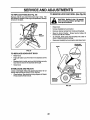
TO REPLACE
(See
MOWER
AND ADJUSTM
BLADE
DRIVE
BELT
WITH PARKING BRAKE _ENGAGEO =
Fig. 22)
The mower blade drive belt may be replaced without
tools. Park the tractor on level surface. Engage parking
brake. For assistance, there is a belt installaUon guide
decal on the mower housing.
BELT REMOVAL•
Place attachment clutch in =DISENGAGED" position=
•
Move attachment lift lever forward to lower mower to
its lowest position.
•
Roll belt off engine pulley.
•
Disconnect R.H. suspension arm from rear deck
bracket by removing retainer spring.
•
Work belt off both mandrel pulleys and Idler pulleys.
NUT "A°
JAM NUT
OPERATING
ARM
,
Pull belt away from mower.
BELT INSTALLATION •
Install new belt in reverse order of removal.
•
Make sure belt is tn all pulley grooves and inside all
belt guides.
MANDREL
R,H. SUSPENSIONARM
FIG. 23
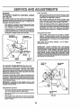
TO REPLACE
MOTION
DRIVE BELT (See
Fig. 24)
Park the tractor on level area. Engage parking brake.
For assistance, there is a belt installation guide decal on
bottom side of left footrest.
•
Remove mower (See "TO REMOVE MOWER" in this
section of this manual).
•
Remove belt from stationary idler and clutching idler.
,
Remove belt from engine pulley.
,
Roll belt over top of transaxle pulley.
•
Install new belt by reversing above procedure.
ENGINE PULLEY
PULLEYS
RETAINER
SPRING
IMPORTANT: REPLACE ONLY WiTH BELT LISTED
IN THIS MANUAL.
MANDREL
PULLEY
FIG. 22
TO ADJUST BRAKE (See Fig. 23)
Your unit is equipped with an adjustable brake system
which is mounted on the rightside of the transa:_Je.
If unit requires more than six (6) feet stoppingdistance at
high speed in highest gear, then brake mustbe adjusted.
•
•
Depressclutch/brake pedal and engageparking brake.
Measure distance between brake operating arm and
nut "A" on brake rod,
•
If distance is other than 1-1/2,. disengage parking
•
g
brake, loosen jam nut and turn nut A until dtstance
becomes 1-1/2, Retighten jam nut against nut A.
I$
•
•
II
PULLEY
II
Engage parking brake and recheck distance.
Road test unit for proper stopping distance as stated
above. Readjust if necessary, If stopping distance is
still greater than six (6) feet in highest gear, further
maintenance is necessary. Contact your nearest authorized service center.
STATIONARY
IDLER
FIG. 24
20
SERVICE AND ADJUSTMENTS
=_ .,.o
._, . ............
TO ADJUST
STEERING
WHEEL
TO START
ALIGNMENT
If steering wheel crossbars are not horizontal (leftto right)
when wheels are positioned straight forward_ remove
steering wheel and reassemble per instructions in the
Assembly section of this manual
FRONT
WHEEL
ii
Replace washers and snap retaining ring securely in
axle groove.
°
Replace hub cap.
BATTERY
I1'1
"1
:
,;,,,;
;.
:: :::::
IMPORTANT:
YOUR UNIT IS EQUIPPED WITH A 12
VOLT NEGATIVE GROUNDED
SYSTEM.
THE OTHER
VEHICLE
MUST ALSO BE A 12 VOLT NEGATIVE
GROUNDED
SYSTEM. DO NOT USE YOUR TRACTOR
BATTERY TO START OTHER VEHICLES°
TO ATTACH JUMPER CABLES Connect each end of the RED cable to the POSITIVE
(+) terminal of each battery, taking care not to short
against chassis.
e
Connect one end of the BLACK cable to the NEGATIVE (-) terminal of fully charged battery.
.
Connect the other end of the BLACK cable to a good
CHASSIS GROUND, awayfrom fuel tank and battery.
TO REMOVE CABLES, REVERSE ORDER •
BLACK cable first from chassis and fully charged
battery,
.
RED cable last from both batteries.
NEGATIVE TERMINAL
POSITIVE TERMINAL
WASHERS
RETAINING
RING
I
HUB CAP
_SQUARE
M
Ii
H
If your battery is too weak to start the engine, It should be
recharged. If "Jumper cables" are used for emergency
starting, follow this procedure:
TO REMOVE
WHEEL
FOR REPAIRS
(See
Fig. 25)
•
Block up axle securely.
o Remove hub cap, retaining ring and washers to allow
wheel removal (rear wheercon_ains a square key- Do
not lose).
•
A WEAK
........
The front wheel toe-in and camber are not adjustable on
your tractor. If damage has occurred to affect the front
wheel toe-in or camber, contact your nearest authorized
service center.
Repair ttre and reassemble.
On rear wheels only: align grooves in rear wheel hub
and axle= Insert squarekey.
WITH
ateexploslvegases, Keepsparks,flame
and smoking materials away from batterles.
Always
wear batteries
eye protection
CAUTION=
Lead-acid
generwhen around batteries.
i
TOE-IN/CAMBER
•
•
ENGINE
(See Fig, 26)
KEY
(REAR WHEEL ONLY)
FIG, 25
CABLES
CHARGED
BATTERY
POSITIVE TERMINAL
NEGATIVE TERMINAL
FIG. 26
21
AND ADJUSTMENTS
TO REPLACE
TO REMOVE HOOD AND GRILL (See Fig. 28)
FUSE (See Fig. 27)
Replace wit_.30 amp automotive+type plug+in fuse. The
fuse holder iS located in the engine compartment,directly
in front of the dash.
CAUTION: Muffler Is hot. Be careful
when removing retainer springs from
hood pivot brackets,
, FUSE
HOLDER
•
Raise hood,
•
Unsnap headlight wire connector+
•
,
Remove retainer spdngs from hood pivot brackets.
Stand in front of tractor. Grasp hood at sides, tilt
forward and lift off of tractor.
•
To reinstall, slide hood pivot brackets into slots in
frame. Replace retainer springs.
•
Reconnect headlight wire connector and close hood.
HEADUGHT
CONNECTOR
HOOD
FIG. 27
TO REPLACE
HEADLIGHT
BULB
•
Raise hood+
•
Pull bulb holder out of the hole in the backside of the
grill.
Replace bulb in holder and push bulb holder securely
back intothe hole in the backside of the grill+
Close hood+
°
,
INTERLOCKS
AND RELAYS
Loose or damaged wiring may cause your tractor to run
poorly, stop runningor prevent it from starting+
•
Check wiring. See electrical wiring diagram in Repair
Parts section of this manual.
REMOVE
RETAINER
SPRINGS
,,,,,
iJl,t,tm,,,,J,,J,,J,,..,JJl,
FIG. 28
22
CE A
ADJU
FINAL SETTING -
ENGINE
TO
ENT$
ADJUST
THROTTLE
CONTROL
CABLE
•
Start engine and allow to warm for five minutes. Make
final adjustments with engine running and shift/motion
controllever in "NEUTRAL position°
,
Move throttJe control lever to "SLOW" position. With
finger, rotate and hold throttle lever against Idlespeed
screw. Turn Idle speed screw to attain 1750 RPM.
•
While still holding throttle lever against idle sReed
screw, turn idle m]xture valve In (clockwise) unUlenginebegins to die and then turn out (counterclockwise)
until engine runs rough. Turn valve to a point midway
between those two positions. Release throttle lever.
(See Fig. 29)
The throttle control has been preset at the factory and
adjustment shouldnot be necessary. Check adjustment as
described below before loosening cable. If adjustment is
necessary, proceed as follows:
•
With engine not running, move throttle control lever
from "SLOW"to =CHOKE" position. Slowtymove lever
from =CHOKE" to "FAST" position.
o Checkthatholes"A" lngovernorcontrolleverandhole
in governor plate line-up. If holes "A" are not aligned,
loosen clamp screw and movethrottle cable untilholes
are aligned. Tighten clamp screw securely.
ACCELERATION TEST °
GOVERNOR
CONTROL LEVER
GOVERNOR
CONTROLPLATE
Move throttle control lever from "SLOW _ to "FAST _
position. If engine hesitates or dies, turn ldle mixture
valve out (counterclockwise) llSturn. Repeattest and
continueto adjust, tf necessary, until engine accelerates smoothly.
Htgh speed stop is factory adjusted.
damage may result.
Do not adjust.
IMPORTANT:
NEVER TAMPER WITH THE ENGINE
GOVERNOR, WHICH IS FACTORY SET FOR PROPER
ENGINE SPEED. OVERSPEEDING
THE ENGINE ABOVE
THE FACTORY
HIGH
SPEED
SETTING
CAN BE
DANGEROUS,
IFYOU THINKTHE ENGINE-GOVERNED
HIGH SPEED NEEDS ADJUSTING,
CONTACT YOUR
NEAREST AUTHORIZED SERVICE CENTER, WHICH HAS
PROPER EQUtPMENT AND EXPERIENCETO
MAKE ANY
NECESSARY ADJ USTMENTS,
HOLES "A"
CLAMP
SCREW
THROTTLE
CABLE
FIG, 29
THROTTLE
LEVER
IDLE SPEED
SCREW
TO ADJUST
CARBURETOR
(See Fig, 30)
The carburetor has been preset at the factory and adjustment should not be necessary. However, minor adjustment maybe requiredto compensatefor differences infuel,
temperature, altitude or toad. if the carburetor does need
adjustment, proceed as follows:
In general, turning idle mixture valve in (clockwise) decreases the supplyoffuelto the engine givinga leanerfuel/
air mixture. Turning the idle mixture valve out (counter*
clockwise)increases the supplyof fuel to the engine giving
a richer fuelialr mixture.
IMPORTANT: DAMAGE TO THE NEEDLE VALVE AND
THE SEAT IN CARBURETOR
TURNED IN TOO TtGHT_
MAY RESULT IF SCREW IS
PRELIMINARY SETTING •
Air cleaner assembly must be assembledto the carburetor when making carburetor adjustments.
•
Be sure the throttle control cable is adjusted properly
(see above).
With engine off turn Idle mixture valve In (clockwise)
closing it finger tight and then turn out (counterclockwise) 1 full turn.
-
IDLE MIXTURE
VALVE
FIG, 30
23
STORAGE
ENGINE
Immediately prepare your tractor for storage at the end of
the season or ifthe unitwill notbe used for30 days or more.
FUEL SYSTEM
IMPORTANT:
IT IS IMPORTANT
TO PREVENT
GUM
DEPOSITS FROM FORMING IN ESSENTIAL FUEL
SYSTEM PARTS SUCH AS CARBURETOR, FUEL FILTER,
FUEL HOSE, OR TANK DURING STORAGE. ALSO,
EXPERIENCE INDICATES THAT ALCOHOL BLENDED
FUELS (CALLED GASOHOL OR USING ETHANOL OR
METHANOL) CAN ATTRACT MOISTURE WHICH LEADS
TO SEPARATION AND FORMATION OFACIDS DURING
STORAGE. ACIDIC GAS CAN DAMAGE THE FUEL
SYSTEM OF AN ENGINE WHILE IN STORAGE,
° Drain the fuel tank_
CAUTION: Never store the tractor wlth
where
fumes
may
reach
an open
flame
gasoline
In the
tank
Inslde
a building
or spark, Allow the engine to cool
before storing In any enclosure,
TRACTOR
Remove mower from tractor for winter storage. When
mower Is to be stored for a period of time, clean it thoroughly, remove all dirt, grease, leaves, etc. Store In a
clean, dry area.
•
Clean enttretmctor (See "CLEANING" Inthe Customer
Responsibilitiessection of this manual)_
,
Start the engine and let tt run until the fuel lines and
carburetor are empty.
•
Never use engine or carburetor cleaner productsInthe
fuel tank or permanent damage may occur.
Use fresh fuel next season.
•
NOTE: Fuel stabilizer is an acceptable alternative In
minimizingthe formation of fuel gum deposits during storage. Add stabilizer to gasoline in fuel tank or storage
container. Always follow the mix ratio found on stabilizer
container. Run engine at least 10 minutes after adding
stabilizer to allow the stabilizer to reach the carburetor. Do
not drainthe gas tank and carburetor if usingfuel stabilizer.
,
•
Inspect and replace belts, if necessary (See belt replacement instructionsInthe Service and Adjustments
section of this manual).
Lubricate as shown In the Customer Responsibilities
section of this manual.
•
Be sure that all nuts, bolts and screws are securely
fastened. Inspect movingpartsfordamage, breakage
and wear. Replace if necessary°
•
Touch up.all rusted or chipped paint surfaces; sand
lightly before painting.
ENGINE
OIL
Drain oil (with engine warm) and replace with dean enqtne
oil (See "ENGINE' in the Customer Responsibilities
section of this manual).
BATTERY
°
Fully charge the battery for storage.
CYLINDERS
•
After a period of time in storage, battery may require
recharging.
°
Remove spark plug(s).
•
Pour one ounce of oil through spark plug hole(s) into
cylinder(s).
•
Turnignitionkeyto START positionforafewseconds
to distributeoil
•
Replace with new spark plug(s).
•
TO help prevent corrosion and power leakage during
long penods of storage, battery cables should be
disconnected and battery cleanedthoroughly (see "TO
CLEAN BATTERYAND TERMINALS" tnthe Customer
Responsibilities section of this manual).
•
After cleanlng, leave cables disconnected and place
cables where they cannot come in contact with battery
terminals.
•
Be sure battery drain tube Is securely attached.
it
it
OTHER
•
Do not store gasoline from one season to another,
•
Replace your gasoline can if your can starts to rust.
Rust and/or dirt In your gasoline will cause problems.
•
If possible, store your unit Indoors and cover it to give
protectionfrom dust and dirt.
•
Cover your unit with a suttable protective cover that
does not retain moisture. Do not use plastic. Plastic
cannotbreathe which allowscondensation toform and
will cause your unit to rust.
IMPORTANT:
NEVER COVER TRACTOR WHILE ENGINE
AND EXHAUST AREAS ARE STILL WARM.
24
TRO
PROBLEM
CAUSE
Will not start
1.
2.
3,
4.
5.
6o
7.
POINTS
CORRECTION
1.
2.
3.
4.
5.
e.
7.
Fitlfuel tank.
See "TO START ENGINE"in OpereUonsection.
Walt severalminutes beforeatlempUngto staff,.
Replacesparkplug.
Clean/replaceair filter.
Replacefuelfilter.
Drainfuel tankand carburetor,refilltankwithfresh
gasolineand replacefuelfilter.
8, Check all wiring.
9. ContactSears Service Center/Depatlment.
10, ContactSears Service Center/Department,
Out of fuels
Engine not =CHOKED = properly,
Engine flooded,
Bad spark plugs
Dirty air fiiter.
Dirt'=/fuelfilter.
Water In fuel,
8. Looseor damagedwiring.
9. CarburetoroutofadjustmenL
10. Enginevalvesoutofadjustment,
Hardto start
1.
2.
3,
4,
5,
6,
7,
8.
Dirty air filter.
Bad spark plug,
Weak or dead battery,
Dirty'fuel filter.
_mle or dirty fuel,
Loose or damaged wiring,
Carburetor out of adjustment.
Engine w{ves out of adjustment,
1.
2.
3.
4.
5.
6.
7.
8°
Clean/replaceair filter.
Replacesparkplug.
Rechargeor replacebattery.
Replacefue! filter.
Drainfuel tank andrefillwithfreshgasoline.
Check all w_dng.
ContactSeats Service CenteriDeperbnent`
ContactSears ServiceCenter/Depertment`
Engine wilt notturn over
1. Clutch/brakepedalno_depressed.
2. AttachmentclutchIs engaged.
3. Weak or deadbattery.
4. Blownfuse.
5. Corrodedbatteryterrninais_
6. Loose or damagedw[dngo
7, Faultyignitionswitch°
8. Faultysolenoidor starter,
9. Faultyoperator presenceswitch(as).
I.
2.
3_
4.
5,
6.
7.
8.
9.
DepressclutcWbmke pedal.
Disengageattachmentclutch.
Rechargeor replacebattery.
Replacefuse°
Clean batteryterminals.
Checkall widng,
Chectdreplaceignitionswitch,
Check/replacesolenoid or starter.
Contact Seers Service Center/Department.
Engine clicksbut will not
start
1.
2.
3o
4.
Weak ordead betters/.
Corroded batteryterminals.
Loose or damsgedwiring.
Faultysolenoidor starter°
1.
2.
3.
4.
Rechargeor replacebattery.
Clean batteryterminals.
CheckeJiwiring.
Check/replacesolenoidor stinters
Lose of power
1.
2.
3_
4.
5.
6.
7o
8.
9.
Cuffingtoomuchgrass/toofast,
Throttlein "CHOKE"position.
Build-upofgrass,leavesand trashundermower.
D_rtyair filter.
Low eli level/dirtyoIL
Faultysparkplug.
Dfrtyfuel filter.
Stale or dirty fuel
Waterin fuel.
10.
tl.
12.
13.
14o
15o
Sparkplugwire loose.
Dirtyengineair screen/fins.
Dlrtylclogged
muffler.
Looseor damagedwidng.
Carburetoroutof adjustment.
Enginevalvesoutof adjustment.
I. Set in =HigherCut" position/reduce
speed.
2. Adjustthrottlecontrol.
3. Clean undersideof mowerhousing.
4. Clean/replaceair filter.
5. Checkell levaVchangeoil.
6. Clean andregapor changesparkplug.
7. Replacefuel filter.
8, Drainfuel tank andre;illwith fresh gasoline.
9, Drainfueltank andcarburetor,refitltankwithfresh
gasolineand replacefuel fitter.
10. Connectand tightensparkplugwire.
11_ Clean engineair screen/fine.
12. Clean!replacemuffler.
13. Checkall wiring.
14. ContactSears ServiceCenter/Depe,_nant`
15_ ContactSears Servtce Center/Depe.rbnent`
iii
Excessivevibration
1.
2,
3,
Worn, bent or loose blade.
Bent blade mandrel,
Loose/damaged part(s).
1.
2.
3,
25
Replace blades Tighten blade boil
Replace blade mandrel.
Tighten loose part(s), Replace damaged parts°
TROU
OOTING POINTS
_t
JHLI_HUU
PROBLEM
CAUSE
CORRECTION
EnginecontinuestO run
when operatorleaves unt
with attachment clutch
engaged
1. Fault/operator.safsty
presence
control
system.
1.
Checkwtdng,switchesand conneotlons,If not
corrected,contactSears ServiceCenter/Depertment.
Poorcut - uneven
1.
2.
3_
4.
5_
1,
2.
3_
4_
5.
Replaceblade. Tightenbladebell
Levelmowerdeck,
Cleanundersideofmowerhousing.
Replaceblademandrel,
Cleanaroundmandrelsto openvent holes.
Mowerbladeswill not
rotate
Obstruction
tn dutch mechanism.
2o W_n]damagedmower drivebelt*
3=
Frozenidlerpulley_
4. Frozenblademandrel
t.
2o
3.
4_
Removeob_ct[on.
Replacemower drivebell
ReplaceIdler pulley.
Replaeablademandrel,
Poor grassdischarge
1.
2,
3,
4.
5.
B,
7_
8,
9.
10,
11=
Worn,bentor looseblade,
Mowerdecknotlevel.
Buildupofgrass,leaves,andtrashundermower,
Bentblademandrel.
Cloggedmowerdeckventholesfrom buildupof
grass,leaves,and trasharoundmandrels°
Enginespeedtoo slow.
Travelspeedtoofast,
Wet grass.
Mowerdecknotlevel,
Low/unevantire_drpressure°
Worn,bentor loose blade.
Buildupof grass,leavesand trashundermower,
Mowerddvebeltworn.
BladesImproperly Instafled.
Improperbladesused.
Cloggedmowerdeckventholesfrom buildupof
grass,leaves,andtrasharound mandrels.
1.
2.
3.
4.
5.
6,
7.
8,
9.
10.
tl.
PlacethrottlecontrolIn =FAST"positton_
Shiftto slowerspeed.
AJlowgrossto dry beforemowing.
Level mowerdock,
Checktires forproperatrpressure.
Reptace/sherpen
blade, Tightenblade boll
Clean undersideofmowerhousing.
Replacemower drivebelt,
Reinstallbladessharpedgedown.
RepIacewith bladeslistedIn thismanual,
Cleanaround mandrelsto openventholes,
Headllght(s)not working
(if so equipped)
I.
2.
3o
4.
5.
Switch is "OFF"_
Bulb(s) burned out_
Faulty light switch.
Loose or damaged widng,
Blown fuse.
I_
2o
3.
4.
5_
Turn switch =ON'.
Replace bulb(s),
Check/replace tight switch,
Check wiring and connections.
Replace fuse.
Battery will not charge
1.
2.
3,
4.
Bad batterycoil(s).
Poorcableconnections.
Fau_yregulator(tf so equipped).
Faultyalternator,
1.
2.
3.
4.
Reptacebattery,
Check/cleanall connections.
Replaceregulator,
Replacealternator.
Engine "backfires"
when turning engine
"OFF"
1.
Enginethrottlecontrolnotset at 'SLOW"
positionfor 30 secondsbeforestoppingengine,
1,
Movethrottle controlto "SLOW"pos_en andallow
to Idle for 80 seconds beforestopping engine.
26
t2 HP 38" TRACTOR - - MODEL NUMBER 917.257281
SCHEMATIC
°111°
BATTERY
RED
FUSE 30 AMP,
I
i
I
STARTER
WHITE
|_
L .....
_
_
SOLENOID
BLACK
IGNITION SWITCH
I
I
I
_l
I
/:
I
I
I
|
I
I
I
I
I
I
I
I
SLACK
CLUTCH/BRAKE
(PEDAL UP)
BLACK
I
i
I
SEAT
SWITCH
(NOT OCCUPIED)
I ATT_MENT CLUTCH
(CLUTCHOFF)
_D
SPARK
PLUG e------_ D
BLACK
(_
I
IGNITION
UNIT
RED
ALTERNATOR
3 _J_PSoc_L_
2OVOLTSAC t_N.)
@ 3600 RPM
(BATTERY IN UNE)
IGNITION SWITCH
POSITION
CIRCUIT
O_F
M;_
ON
- START
----eP---
B+ L
i
B÷S
NON-REMOVABLE
CONNECTIONS
NOTE
YOUR TRACTOR iS EQUIPPED
WITH A SPECIAL ALTERNATOR
SYSTEM. THE LIGHTS ARE NOT
CONNECTED TO THE BATTERY,
BUT HAVE THEIR OWN
ELECTRICAL SOURCE.
BECAUSE OF THIS, THE BRIGHTNESS OF THE LIGHTS WILL
CHANGE WITH ENGINE SPEED.
AT IDLE THE LIGHTS WILL DIM.
AS THE ENGINE IS SPEEDED UP,
THE LIGHTS WILL BECOME
THEIR BRIGHTEST°
_
REMOVABLE
CONNECTIONS
27
sAMPS ALTERNATOR
@ 11VOLTS/,_e,
@ _,e0o
F_M.
o_
C'_
'__
P
I.....
: i
SWITCH
(OFF)
HEAD
_-'-__.j
o--'_
WIRING INSULATED CLIPS
NOTE: If wiring insulated clips were removed for servicing of unlt, they should
be replaced to properly secure your wiring,
REPAIR PARTS
12 HP 38" TRACTOR - - MODEL NUMBER 917.257281
ELECTRICAL
A
B
12
E
C
3
F
18
33
32
\
J
I
J
16
t
!
\
!
l
1
\
/
\
t
29
|
I
I
1
I
28
REPAIR PARTS
12 HP 38" TRACTOR = - MODEL NUMBER 917,257281
ELECTRICAL
KEY
NO.
1
2
3
4
5
6
7
8
9
10
11
12
13
14
15
16
17
18
19
20
21
22
23
24
25
26
27
28
29
30
31
32
33
34
35
36
37
PART
NO.
121265X
STD365402
124211X
132653
4207J
132202
4799J
129965
109596X
I09081X
STD551125
73350400
74780408
STD551225
STD541425
131563
109553X
STD601005
104445X
STD601005
121305X
121264X
74760412
STD551025
STD551125
STD541025
109310X
108824X
109238X
t23620X
110712X
127441X
7662J
130890
STD601005
108236X
STD601005
DESCRIPTION
Battery 12 Volt 25 Amp
Starter Swtc
Nut Ignitlon
Harness Ign B&s Fender HI
Cable Ground 6ga 12"black
Cable Battery 6 Ga 42 red
Cable Battery 6ga 11"red
Case Battery Hinge Mechanical
Clamp Hose Olive
Solenoid
Lockwasher
Nut Jam Hex 1/4-20 Unc
Bolt Fin Hex 1/4.20uncx1/2 Gr5
Washer
Nut
CoverTerminal Red
Switch Intlk Clutch Red 4 Term
Screw
Switch Intlk Clutch Red 2Term
Screw
Switch Plunger Nc Gray
Caps Battery 25/30 Amp
Bolt Hex Hd 1/4-20unc X 3/4
Washer
Washer
Nut
Key Ign Molded Craftsman
Fuse 30 Amp Auto Green
Tube Plastic 12"
Cover Sw Key BIk 1 25 Text Sit
Switch Light BIk BIk Red
Harness Socket Light
Bulb Light #1141
Bracket Switch Interlock
Screw
Bracket Switch Clutch
Screw
NOTE: All component dimensions given in U, S, inches.
1 inch = 25°4 mm
29
REPAIR PARTS
12 HP 38" TRACTOR - .. MODEL NUMBER 917.257281
CHASSIS
AND ENCLOSURES
A
B
D
£
F
G
H
!
K
L
M
21
17
!
"G
31
3O
37
REPAIR PARTS
12 HP 38" TRACTOR =,. MODEL NUMBER 917o257281
CHASSIS
AND ENCLOSURES
KEY
NO.
1
2
3
4
5
6
7
8
9
10
11
12
13
14
15
16
17
18
19
20
21
22
23
24
25
26
27
28
29
30
31
32
33
34
35
36
37
38
39
40
50
PART
NO.
135034
127866
17490612
STD523707
STD541437
126595X010
17490608
2751R
126604X010
5479J
122795X
121794)(
124031X012
17490608
74180512
STD541431
131445X417
126938X
STD512505
STD551125
122933X
124479X
4921H
STD523707
19131312
STD541437
17490608
123915X
124029X
126599X417
109873X
17490612
105465X417
105464)(417
STD533707
STD541437
105466X
134618
134617
72140606
STD541437
NOTE:
DESCRIPTION
Chassis VVeldment12ga 38/42
Drawbar Lt/yt 11 Ga
Screw Thdrol 3/8-16x3/4 Ty-tt
Bolt
Nut
Saddle Silkscreened
Screw Thdrol 3/8-16xl/2 Ty-tt
Clip Line Fuel 13/32 Mtg Hole
Dash Silkscreened Sears Eng
Plug Button BIk 359 Dia
Panel Pnt Dash Lh
Cover Access Black Square
Panel Slkscr Dash Rh Weldment
Screw Thdrol 3/8-16xl/2 Ty-tt
Screw Mach Trhd 5/16-18uncx3/4
Nut
Hood Asm Pnt Weld Silver Powde
Bumper Hood
Screw
Washer
Rivet Ratchet Nylon
Washer Nylon Blk 28x 75x 19
Retainer Spring
Bolt
Washer 13/32 X 13/16 X 12 Ga
Nut
Screw Thdrol 3/8-16xl/2 Ty-tt
Grille Grey
Lens Headlight Bar Clear
Fender Pnt
Bracket Pnt Fender
Screw Thdrol 3/8-16x3/4 Ty-tt
Footrest Pnt Lh (silver)
Footrest Pnt Rh (silver)
Bolt
Nut
Pad Footrest Rbr Sq Craftsman
Bracket, Assembly Pivot LH Mower Rear
Bracket, Assembly Pivot RH Mower Rear
BoltCarriage 3/8-16 x 3/4
Nut
All component dimensions
1 inch = 25,4 mmo
31
given
in U,S,
inches.
REPAIR PARTS
12 HP 38" TRACTOR - - MODEL NUMBER 917.257281
DRIVE
!
70
66
81
86
45
83
37
5S
3O
8
26_:7 36
3_
I
30
22
.
A
B
C
D
E
F
18
32
G
1
H
67
!
:92
REPARR PARTS
12 HP 38" TRACTOR - - MODEL NUMBER 917,257281
DRIVE
KEY
NO.
PART
NO.
1
2
3
4
5
6
8
10
1!
12
13
14
17
18
I9
20
21
22
23
24
25
26
27
28
29
30
31
32
33
34
35
36
37
38
39
40
41
42
43
44
45
46
47
120897X
1t0422)(
123666X
12000028
121520X
17490512
127270
STD561210
105701X
19t51216
71040412
STD551125
121520X
STD523707
STD541437
17490512
106933X
131867
STD541437
STD541237
106888X
STD55t037
STD561210
128904
124236X
109167X
127275X
STD523707
STD541437
122424X
120183X
STD551062
STD571810
123674X
STD523727
4470J
109070X
19131312
STD541437
105706X
110812X
12000039
127783
DESCRIPTION
KEY PART
NO.
NO.
Transaxle 5sp Std Dana
Spring Return Brake T/a Zinc
Pulle_iTransaxle Alum
RingRetatner # 5100-62
Strap Pnt Torque 30 Deg BIk
ScrewThdrolS/16-18X3/4Tyt
Rod Shifter BIk Zinc 13 17 Lg
Pin Cotter 1/8 X 1 Cad
Washer Plate Shf 388 Sq Hole
Washer 15/32 X 3/4 X 16Ga
BoltFinHexl14-28unfx3/4Gr8
Washer Lock Hvy Helical 1/4
Strap Pnt Torque 30 DEG BLK
Bolt Fin Hex 3/8-16unc X 3/4
NutCrownlock3/8-16Unc
Screw Thdrol 5/16-18 X 3/4 Tyt
Knob Rd 1/2-13 Plstc Thds BIk
Rod BrakeLt
Nut Lock Hex W/wsh 3/8-16unc
Nut HexJam 3/8.,16 Unc
Spring RodBrake 2 00 Zinc
Washer13/32 X13/16 X16 Ga
Pin Cotter 1/8 X 3/4 Cad
Rod Brake Parking Lt
Cap Parking Brake Red
Bracket Transmission
Keeper Belt Lh Lt t4 Ga
Bolt Fin Hex 3/8-16unc X 3/4
Nut Crownlock 3/8-16 Unc
ShaftAsmPedatFoot1930
Bearing Nylon Blk 629 Id
Washer21/32X1
X16Ga
Pin Roll 3/t6 X 1
Pulley Idler Flat
Bolt Fin Hex 3/8-16unc X 2-3/4
Spacer Split 395X 59Bzp
Keeper Belt Retainer
Washer13!32 X13/16 X12 Ga
NutCrownlock3i8-16Unc
Bearing Nyl 503 X 628 X t 25
Washer Hardened
Ring Kllp #t5304-50
Pulley Idler V Groove Plastic
48
49
50
51
52
53
54
55
56
57
58
59
60
61
62
63
64
65
66
67
68
69
70
71
72
73
74
75
76
77
78
80
81
82
83
84
85
86
87
88
89
90
91
93
DESCRIPTION
123789X
123205X
STD523715
STD541437
STD551037
105710X
STD5612t0
105709X
STD5612t0
125907X
127274X
1047TIX
19131312
17490612
8883R
134825
71170764
STD551143
129921
STD523710
19131312
STD541437
134683
STD523710
19132012
STD541437
109502X
t2t749X
STD581075
123583X
121748X
123794X
136934
123782X
19171216
123793X
73530400
71208X
19212016
12000008
131635
124346X
STD523727
STD54t437
Bellcrank Asm
Retainer Belt Style Spring
Bolt Hex Hd 3/8-16unc X 1-1/2
Nut Crownlock 3/8-t6 Unc
Washer 13/32 X 13/16 X 16 Ga
Link Clutch 7 66
Pin Cotter 1/8 X 3/4 Cad
Spring Return Clutch 6 75
Pin Cotter 118 X 3/4 Cad
V-belt Ground Drive 90 00
Keeper Belt Rh Lt PnUzlnc 16g
Retainer Belt Chassis LH Zinc
Washer 13/32 X 13116 X 12 Ga
Screw Thdroi 3/8-16-x3/4 Ty.tt
Cover Pedal Blk Std
Pulley Engine
Bolt Finhex 7/16-20 x 4 Gr. 5
Washer Lock Hvy Hlcl Spr 7/16
Keeper Belt Engine LH Lt
Bolt Fin Hex 3/8-16unc X 1
Washer 13/32 X 13/16 X 12 Ga
Nut Crownlock 3/8-16 Unc
Guide Belt Dr Mower RH
Bolt Fin Hex 3/8-16unc X 1
Washer 13/32 X 1.1/4 X 12 Ga
Nut Crownlock 3/8-16 Unc
Spacer Split 80x 94 Cad/zinc
Washer 25/32 X 1 1/4 X 16 Ga
Ring E
Key Square 2 0 X 1845/1865
Washer 25/32 X 1 5/8 X 16ga
Arm Pnt Shift T/a
Shaft Asm Pnt Shifter
Spring Torsion T/a
Washer 17/32 X 3/4 X 16ga
Rod Unk Shift Adj 3 710
Nut Nylock 1/4-28
Bushing Pivot W/180 Step Pm
Washer
E Ring
Console Shift 5sp W/tgn Lt Srs
Nut Self-thd Wsh-hd 1/4 Zlnc
Bolt Fin Hex 3/8-16 x 2-3/4
Nut Crown Lock 3/8-16
NOTE: All component dimensions given In U.S. Inches.
1 inch = 25.4 mm.
33
REPAIR PARTS
12 HP 38" TRACTOR -- MODEL NUMBER 917.257281
STEERING
23
ASSEMBLY
24
29
25
26
34
REPAURPARTS
12 HP 38" TRACTOR - - MODEL NUMBER 917,257281
STEERING
ASSEMBLY
KEY
NO.
1
2
3
4
5
6
7
8
9
10
11
12
13
14
15
16
17
18
19
20
21
22
23
24
25
26
27
28
29
30
31
32
33
34
35
36
37
38
39
40
41
42
43
44
45
46
PART
NO.
133741
131450
135227
135228
6266H
121748X
19272016
12000029
3366R
130468
STD551137
73610600
110438X
74011056
73601000
132624
132614
57079
124035X
126684X
STD551125
71070410
127501
109816X
124036X
12000029
124034X
6266H
17490612
STD551137
73610600
130465
126847X
19131416
STD561210
132196
STD611005
133742
19133808
STD541537
104820X
124417X
121749X
121748X
12000029
121232)(
NOTE:
DESCRIPTION
Wheel Steering
Axle asm Front
Spindle Asm Lh
Spindle Asm Rh
Beadng Race Thrust Harden
Washer 25/32 X t 5/8 X 16ga
Washer 27/32 X 1 1/4 X 16 Ga
Ring Klip #t5304-75
Bearing Col Strg Blk
Unk DragSol Bali Jt 20 064
Loclo,,_asher
Nut Fin Hex 3/8.24 Unf
Spacer Bearing Axle Front
Bolt Hex 5/8-tl Unc X 3-1/2
Nut Hex Jam Lk W/wh 5/8-11 Unc
Pin Axle 5/8 X 1 55/t 54 Lg
Shaft Asm Strg 5/8X 15 19 Lt
Washer Thrust 515x 750x 033
Support Shaft
Washer Shim 1/4 X 5/8 X 062
Washer
Screw Hex Socket 1/4-20 X 5/8
Shaft Asm Pittman
Nyltner Snap In
Bracket Steering
Ring Kltp #t5304-75
Gear Sector
BeadngRace Thrust Harden
Screw Thdrol 3/8-16x314 Ty,.tt
Lockwasher
Nut Fin Hex 3!8-24 Unf
Rod Tie Wire Form 19 75 Meeh
Bushing
Washer 13/32 X 7/8 X 16ga
Pin
Bushing Strg 5/8 Id Dash
Screw
Insert Cap Strg Wheel
Washer 13/32 X 2-3/8 X 8 Ga
Gripco Nut
Adaptor Wheel Strg 640/635id
Boot Shaft Steering
Washer 25/32 X 1 1/4 X 16 Ga
Washer 25/32 X 1 5/8 X 16ga
Ring Klip #t5304-75
Cap Spindle Fr Top BIk
All component dimensions given in U.S. Inches.
1 inch = 25.4 mm.
35
REPAIR PARTS
12 HP 38" TRACTOR - - MODEL NUMBER 917.257281
SEAT ASSEMBLY
1
E
10
c
A
_19
KEY
NO.
PART
NO.
1
2
3
4
5
6
7
8
9
10
11
12
13
127436
126656X
STD523707
19131210
2751R
STD541437
124181X
17490616
19131614
131451
121251X
121246X
121248X
DESCRIPTION
KEY
NO,
PART
NO.
Seat V250 BII4red Craftsman
Bracket Pnt Pivot Seat (blk)
Bolt
Washer 13/32 X 3/4 X 10 Ga
Clip Line Fuel 13/32 Mtg Hole
Nut
Spring Seat Cprsn 2 250 BIk Zi
Screw Thdrol 3/8-16 X t Ty-tt
Washer 13/32 X t X 14 Ga
an Pnt Seat (blk)
rip Foam Gray Or Black
Bracket Pnt Mounting Switch
Bushing Snap Blk Nyl 50 Id
14
15
16
17
18
19
20
21
22
23
24
25
26
72050411
121249X
121250X
123976X
STD511005
73951000
4171R
105529X
STD541431
74780814
19171912
127018X
STD551150
DESCRIPTION
Bolt Rdhd Sht Nk 1/4-20xl-3/8
Spacer Split 28 X 88 Zinc
Spring Cprsn 1 27 BIk Pnt
Nut Lock 1/4 Lge Fig Gr 5 Zinc
Screw
Nut Keps #10-32 Unf
Clip Insulated t 1/32 Mtg Hole
Bolt Shoulder 5/16-18 Unc Blkz
Nut
Bolt Fin Hex 1/2-13 X 7/8 Gr 5
Washer 17/32 X 1-3/t6 X 12 Ga
Bolt Shoulder 5/16-18 X 62
Lockwasher
NOTE: All component dimensions given in UoS.inches,
1 inch = 25,4 mm.
36
REPAIR PARTS
12 HP 38" TRACTOR =- MODEL NUMBER 917,257281
DECALS
13
18
6
3
7 8
19
5
8
7 4
13
10
9
15
11
16
12
17
14
KEY
NO.
PART
NO.
1
2
3
4
5
6
7
8
9
10
108456X
126685X
124489X
124490)(
132674 •
133644
126770X
108631X
125880X
133796
DESCRIPTION
KEY
NO,
Decal
Decal
Decal
Decal
Decal
Decal
Decal
Decal
Decal
Decal
11
12
13
14
15
16
17
18
19
m
Instruction Operat Eng
Engine 12hp Ic B&s Craft
Hood Slope Rh Craftsman
Hood Slope Lh Craftsman
Grille Lt4000 Craft Usa
Maint Customer Sears Dom
Panel Side 12 Pip Ic
li(die Cut)
Fender Craftsman Red
Caution English
KEY
NO.
11
PART
NO.
4900J
109199X
105809X
13o929
121343X
3713J
133179
132267
131265
135975
PART
NO.
1
2
3
4
5
6
7
59192
65139
106222X
59904
106732X361
278H
9040H
8
9
10
11
106t08X361
3588R
7152J
104757X
DESCRIPTION
Decal Clutch/brake English
Decal V-belt Dr Sch Tractor E
Decal Chassis 5sp 38"
Decal Mower Drive Schematic 38
Decal Danger English
Decal Rota Blades English
uecal Mower Qc System
Decal Insr Wh Strg Crafts Usa
Decal Light Box, Grill
Manual Owner's
DESCRIPTION
Cap Value Tire
Stem Value
Tire F Ts 15 X 6 0 - 6 Service
Tube Front (Service Item Only)
Rim Asm 6"front Silver Service
Fitting Grease (Front Wheel only)
Bearing Flange (Front wheel
Only)
Rim Asm 8"rear Silver Service
Tire R Ts 18x8 5-8 S Service
Tube Rear (Service Item Only)
Cap Axle BIk 1 50 X 1 00
NOTE: All component dimensions given tn U.S. incheso
1 inch - 25.4 mm°
37
REPAIR PARTS
12 HP 38" TRACTOR - - MODEL NUMBER 917.257281
ENGINE
F
G
X
I
_12
_17
_11
_7
3
J
5
36
32
\
,36
31
B
/
B
33
37
14
27
o
38
22
21
25
30
19
23
OPTIONAL
EQUIPM ENT
Spark Arresier
38
18
J
_6
REPAIR PARTS
12 HP 38" TRACTOR =- MODEL NUMBER 917.257281
ENGINE
KEY
NO.
1
2
3
4
5
6
7
8
9
10
11
12
13
14
15
16
17
18
19
20
21
22
23
24
25
26
27
29
30
31
32
33
34
35
36
37
38
PART
NO.
132759
17720410
131951
125610X
101326L
17030808
STD551025
STD551125
STD522510
73220500
STD551131
71070510
125593X
13280324
13200300
STD551237
17490620
105736X
105839X
105838X
STD551025
123650X
128953
STD601005
124027X
17030808
105037X
121851X
127057X
109202X
123549X
123487X
124028X
17490412
19091416
101335K
NOTE:
DESCRIPTION
Control Throt Rh Bik Pd115 10
Screw Hex Thd Cut 1/4-20x5/8 T
Engine B&s 12hp i!c Dual 1 Vt
Muffler Exhaust B&s Lt Std
Deflector Muffler # 222573
Screw Spiderloc Hexhd#8xl/2 Ab
Washer
Washer
Bolt
Nut Hex 5/16-18
Lockwasher
Screw Hexhd Cap 5/16-18x5/8
Gasket 1 313 ld Tin Plated
Nipple Pipe 3/8 Npt X 3"
Elbow Std 90 Degree 3/8-18 Npt
Washer
Screw Thdrol 3/8-16xl -1/4 Tytt
Shield Pnt Heat
Receptacte 1/4 Turn Dacrotized
Retainer 1/4 Turn 365odx 222id
Washer
Stud 1/4 Turn (replaces 105751)
Shield Pnt Heat Browning Grass
Screw
Shield Pnt Heat Hood Lt
Screw Spiderloc Hexhd#8xl/2 Ab
Strip Foam 18"
Arrestor Spark
Pinch Weld Hood Black 2 00
Tank Fuel t 25 Fr
Cap Asm Fuel W/sym Vented
Cia .rapHose Blk
Bushing Snap Nyl BIk Fuel Line
Screw Hexwsh Thdrol 1/4-20x3/4
Washer 9/32 X 7/8 X 16ga
Line Fuel 9 50"
Plug Oil Drain (Order From Engine
Manufacturer)
All component dimensions given in U.S. inches.
1 inch = 25°4 mm.
39
REPAIR PARTS
12 HP 38" TRACTOR =- MODEL NUMBER 917.257281
38" MOWER
52
75
76
_,72
+
45
44
45
46
53
55
73
51
5o
61
63
32
1
,31
+l
24
27
24
23
20
+
I
3
15
------7
4O
3
16
I
REPAIR PARTS
12 HP 38" TRACTOR =- MODEL NUMBER 917.257281
38" MOWER
KEY
NO.
PART
NO.
1
2
3
4
5
6
7
8
129365
STD54143i
STD533107
7631J
110485X
128774
129895
133172
9
10
11
12
!3
14
15
16
17
18
19
20
21
22
23
24
25
26
27
28
29
30
31
32
33
34
38
39
40
41
42
43
127842
129962
STD551137
850857
128961
t06736X
106735X
105896X
110452X
106734X
19111016
105304X
128772
19111216
78158
STD624008
74600636
19131612
127218
73350800
130171
73680800
135388
135563
130832
134619
133840
129963
129206
73050900
131494
122052X
DESCRIPTION
KEY
NO.
Mower Asm 38"welded
Nut
Bolt
Runner Mower Lh 10 00
Bearing Ball Mandrel
Housing Mandrel Vented(machd)
Bearing Ball #6204 (mandrel)
Shaft Asm Mandrel Vented
cludes Key # 79)
ade Mower Htgh Peff 38
Washer Hard Blade Mower Vented
Lockwasher
Bolt 3/8-24xl 25 Gr8 Patched
Stripper Mower Vented
Shield Defector 38
Rod Hlnge BWblk Zinc 9 88 Lg
Bracket Deflector Mower
Nut Push Phos & Oil
Spring Deflector 4 46 Blk
Washer 11132 X 5/8 X 16 Ga
Cap Sleeve 80x 112 Btk Mower
Runner Rh 38"
Washer 1I132 X 3/4 X 16ga
Bolt 5/16-18 X 1 25T/t
Ret Spring
Bolt Hex 3/8-16 X 2-1/4
Washer 13/32 x I x 12 Ga,
Link Front
Nut Jam Hex 1/2-13 Unc
Trunnion Blk Zinc
Nut Crownlock 1/2-13 Unc
Link Lift Rh
Pin Spring
Arm Suspenston
Link Lift Lh
Asm Idler Arm
Washer Spacer Mower Vented
Pulley Mandrel 38" Single
Nut 9/16top Lock Flng Oil Dip
Pulley Idler Flat
Spacer Retainer Pm Mower
44
45
46
47
48
49
50
51
52
53
54
55
56
57
58
59
60
61
62
63
64
65
66
67
68
69
70
71
72
73
74
75
76
77
78
79
80
PART
NO.
19131612
STD54!437
131290
133502
133503
120183X
122507X
105767X
125631X
122365X
122364X
122512X
122514X
STD581062
19211416
131288
131289
STD560907
133551
133504
STD533717
133550
STD541237
133205
STD624003
127498
128759
133573
106932X
121748X
12000029
128903
127845
127847
131870
130840
17490512
131455
130794
DESCRIPTION
Washer 13/32 X 1 X 12 Ga
Nut
V-belt Mower 88 12 38"
Spacer Arm Idler Upper Hdn 42"
Stiffener Arm Idler Upper 42"
Bearing Nylon Blk 629 Id
Shaft Asm Pnt LftWlwo/inf Hgt
Pin Groove 1 500 Zinc
Grip Handle Fluted BIk
Button Plunger Red
Plunger Lever Lift
Spring Cprsn 3 750 Oiled
Rod Asm Lever 9 219 Bend Stake
E Ring
Washer 21132 X 7/8 X 16ga
Rod Brake Mandrel Rh 10 744
Rod Brake Mandrel Lh 4 856
Cotter Pin
Rod Pivot W/nibs
Rod Clutch Secondary W/nibs
Bolt
Rod Clutch Primary W/nibs
Nt,t
Trunnion Adj 3/8-16 Unc X 1 30
Retainer
Bushing 747 Od X 794 Lg Brass
Spring Clutch Mower 2 750 Zinc
Arm Asm Pnt Clutch Primary
Knob Rd 3/8-16 Plstc Thds BIk
Washer 25/32 X t 5/8 X 16ga
Ring Kllp #t5304-75
Bolt Shoulder 318-16 Unc I 44
Keeper Spring 4 000
Arm Clutch Secondary
Spring Retum
Brake Asm Mower Vented
Screw Thdrol 5/16-I8 X 3/4 Tyt
Deck Complete Mower
Mandrel Asm (Includes Key #'s 5-8,
10-12, 39-41)
NOTE: All component dimensions given tn U.S, Inches,
1 inch = 25.4 ram,
41
REPAIR PARTS
12 HP 38" TRACTOR .. - MODEL NUMBER 917.257281
TRANSAXLE
DANA- MODEL NUMBER 4360-6
TRANSAXLE
2O
21
24
25
28
29
3O
2
26
32
33
34
36
37
|
19
40
54
44
45
55
46
56
47
48
49
59
19
6O
58
59
64
73
68
72
61
74
65
66
7O
42
REPAIR PARTS
12 HP 38" TRACTOR ,. = MODEL NUMBER 917.257281
TRANSAXLE
DANA = MODEL NUMBER 4360-6
TRANSAXLE
KEY PART
NO, NO.
1
2
120458X
2274J
3
4
5
6
7
8
12
13
14
15
16
17
18
19
20
21
22
23
24
25
26
27
28
29
30
3t
32
33
34
35
36
37
38
68003
105904X
105905X
120460X
120461X
120462X
120463X
120464)(
120465X
120466X
83818
120467X
2286J
2267J
3413J
2233J
2232J
2231J
2230J
2229J
2228J
2227J
2226J
105906X
6725J
120415X
2257J
110077X
110078X
105909X
105910X
10591tX
108976X
105913X
120468X
2242J
120469X
2244J
105916X
120470X
t10070X
108977X
120405X
108980X
120406X
108455X
!05923X
105825X
2232J
108978X
110079X
39
40
120471X
120472X
9
10
11
KEY PART
NO, NO.
DESCRIPTION
Housing, Upper
Screw, Tapping, Large
t/4-20 x .734
Ball, Detent
Spring, Detent
Screw, Set
Shifter Assembly
O-Ring
* Washer, Plain .505 x .942 x .006
* Washer, Plain .505 x .942 x .010
* Washer, Plain .505 x .942 x .015
* Washer, Plain .505 x .942 x .020
* Washer, Plain .505 x .942 x .026
* Washer, Plain .505 x .942 x .030
* Washer, Plain ,505 x .942 x .040
Ring, Retaining
Ring, Retaining
*Washer, Plain .632 x 1.00 x .010
* Washer, Plain .632 x 1.00 x °020
* Washer, Plain .632 x 1.00 x .026
* Washer, Plain .632 x 1.00 x .03t
* Washer, Plain .632 x 1.00 x .036
* Washer, Plain .632 x 1.00 x .041
* Washer, Plain .632 x 1.00 x .046
* Washer, Plain .632 x 1.00 x .050
* Washer, Plain .632 x 1.00 x .060
* Washer, Plain .632 x 1.00 x .082
O.Ring
Washer, Plain .632 x 1.38 x .046
Key, Woodruff, #9
Kit, Input Shaft Assembly
Pinion, uevel, 14Teeth
Ring, Retaining
Chain, 24 Pitches
Bearing, Flange
Gear, Spur, 14 Teeth
Collar, Clutch
Key, Clutch
Key, Woodruff, #3
Shaft, Intermediate
Key, Woodruff, #61
Ring, Retaining
Sprocket, 18 Teeth
Spacer
Gear, Spur, 37 Teeth
Gear, Spur, 30 Teeth
Gear, Spur, 25 Teeth
Gear, Spur, 22 Teeth
Gear, Spur, 19 Teeth
Spacer 1.133 x 1.50x.375
Washer, Plain .640 x 1.37 x .061
Washer, Plain .632 x 1.00 x .026
Spacer .630 x 1.00 x.169
Assembly, Gear, Combination of
12 Teeth and 35 Teeth
Shaft, Idler
Spacer .635 x ,875 x .755
41
42
43
44
45
46
47
48
49
50
51
52
53
54
55
56
57
105928X
t10084X
108983X
105930X
105931X
t05932X
3417J
106097X
2264J
106098)(
2265J
106586X
106587X
106588X
2263J
120473X
105933X
120407X
t06589X
120408X
105937X
105936X
2226J
2227J
2263J
120474X
110081X
105941X
110071X
58
59
60
61
62
63
64
65
66
67
120952X
110082X
120475X
120476X
120961X
7294J
108989
120953X
120954X
120955X
68
69
70
71
72
108992X
108996X
120956X
73810500
106596X
73
74
75
120993X
120951X
!20416X
*
**
DESCRIPTION
Sprocket, 9 Teeth
Gear, Bevet, 42 Teeth
*Washer, Plain .758 x 1.t2 x .010
* Washer, Plain .758 x 1.12 x .015
* Washer, Plain .758 x 1.!2 x .020
*Washer, Plain .758 x 1.12 x .025
* Washer, Plain .758 x 1.25 x .020
* Washer, Plain .758 x 1.25 x .025
*Washer, Plain .758 x 1.25 x .031
* Washer, Plain .758 x 1.25 x ,035
*Washer, Plain .758 x 1.25 x .040
* Washer, Plain ,758 x t.25 x .045
* Washer, Plain .758 x 1.25 x .050
*Washer, Plain .758 x 1.25 x .055
* Washer, Plain .758 x 1.25 x .062
Shaft, Drive
Gear, Spur, 12 Teeth
Gear, Spur, 20 Teeth
Gear, Spur, 25 Teeth
Gear, Spur, 28 Teeth
Gear, Spur, 31 Teeth
Spacer .781 x 1.00 x .375
Washer, Plain .632 x 1.00 x .060
Seal, Felt
Washer, Plain .758 x 1.25 x .062
Axle, Left Hand
Gear, Miter, 15 Teeth
Ring, Retaining
Gear, Spur, 32 Teeth
Shaft, Cross
Gear, Miter, 15 Teeth
Axle, Right Hand
Housing, Lower
Puck, Friction
Disc, Brake
Spacer
aw, Brake
Pin, Dowel
Screw, Tapping, Large
5/16-18 x 2.25
Lever, Actuating
Washer, Plain .321 x 1.00 x .055
Bracket, Anti_Rotatlon
Locknut 5/16-24
Screw, Tapping, Large
5/16-18 x 1.44
Washer, Plain .343 x .81 x .059
Puck, Friction
Grease
Use in Various Combinations To Maintain Proper
Clearances
Order Key Number 15
NOTE" All component dimensions given In U.S. Inches
1 inch = 25.4 rnm
43
REPAIR PARTS
12 HP 38" TRACTOR - - MODEL NUMBER 917.257281
ENGINE BRIGGS & STRATTON
- MODEL NUMBER
283707, TYPE NUMBER
0217=01
265
657
:30S
663
334
232
j-------t----
307
13
757
219
li
26
G
358
44
524
REPAIR PARTS
12 HP 38" TRACTOR - - MODEL NUMBER 917.257281
ENGINE BRIGGS & STRATTON
- MODEL NUMBER 283707, TYPE NUMBER
121 CARBUP,ETOR OVERHAUL KIT
131
141
618
_634
62
164
51
_105
123
4A
535
©
9
127
224
_138
_ 955
_78
726
423
[ 60e::_t ..........
45
445
17"
0217-01
REPAIR PARTS
12 HP 38" TRACTOR - - MODEL NUMBER 917,257281
ENGINE BRIGGS & STRATTON
- MODEL NUMBER
283707, TYPE NUMBER
0217-01
310
803
801
Reference Number
i
:309
_torand
1111310
I ThrJBo|t
I
i
:3tl
at.=.
e_1............
I
e_
Ddv,t
] Armntum
Bdggs
.StrattonMenufecturer,,
HO_L_
Drive Ass'v" i Assembly i Assembly
Assembly t Assembly
12V .. I 3-21F32"
394e05
"Ir_udes B,'ush Set
"lncJudas
#398003C]utchAsson',bly
t280104 Gear
#490467 Retainer and Pin
€ 94288 R_ Pin
49042!_" I 390837
I
94003
I
395538
(Rof, No_513)
(Ref. No. 783)
(Ref. No. 876)
(RefoNo, 896)
46
_ive End _p
Assembly
394_56
I End Cap _'y,,
I Commutator
!
395537" '
......
I""I:Y"'
eo:3 I
| Housing I
! Assembly I
!
393825
!
REPAIR PARTS
12 HP 38" TRACTOR - - MODEL NUMBER 917,257281
ENGINE BRIGGS & STRATTON
KEY PART
NO. NO.
1
2
490450
399265
3
5
7
8
9
10
11
12
391086
494240
271866
391406
27803
93394
280100
271916
271997
271996
93723
94239
490466
94196
494238
291675
94305
492326
13
15
16
t8
20
22
23
24
25
26
27
28
29
222698
394661
394662
394663
394664
391780
392331
391781
391782
391783
260924
299691
391286
490348
490469
31
32
33
34
35
36
37
40
41
42
45
46
51
222299
92909
262246
262247
65906
26828
223752
221596
292260
93630
262248
212897
272465
52
270872
- MODEL NUMBER 283707, TYPE NUMBER
KEY PART
NO. NO.
DESCRIPTION
Cylinder Assembly
Bearing, Cylinder (Requires Special
Tools For Installation)
*Seal, Oil
Head, Cylinder
*Gasket, Cylinder Head
BreatherAssembly
*Gasket, VaiveCover
Screw, Sems
Tube, Breather
*Gasket, Crankcase Cover 1/64"
* Gasket, Crankcase Cover .005"
* Gasket, Crankcase Cover .009"
Screw, Cylinder Head
Plug, Oil Drain
Crankshaft
Key, Timing Gear
Base, Engine
*Seal, Oi!
Screw, Sems, Base Mounting
Flywheel and Ring GearAssembly,
Magneto
Key, Flywheel
Piston Assembly, Standard
Piston Assembly .010' Oversize
Piston Assembly .02011Oversize
Piston Assembly .030 Oversize
Ring Set, Piston, Standard Size
Ring"Set, Piston, Chrome,,,Standard
Ring"Set, Piston ,010,, Oversize
Ring' Set, Piston .020,, Oversize
Ring Set, Piston .030 Oversize
Lock, Piston Pin
Pro"Assembly, Piston, Standard
Pin Assy., Piston .005 Oversize
Rod Assembly, Connecting
Rod Assembly, Connecting,
.020" Undersize Crankpin Bore
Lock, Connecting Rod Screw
Screw, Connecting Rod
Valve, Exhaust
Valve, Intake
Spring, Intake Valve
Spring, Exhaust Valve
Guard, Flywheel
Retainer, Intake Valve
Rotocoil, Exhaust Valve
Retainer, Exhaust Valve Rotocoil
Tappet, Valve
Gear, Cam
•** Gasket, Carburetor (Carburetor to
Elbow)
• Gasket, Carburetor (Elbow to
Cylinder)
53
75
78
95
98
104
105
106
'108
118
121
123
125
127
130
131
133
137
t38
141
'142
94637
224061
93805
94098
494382
231789
231790
281169
224540
494383
494384
94616
494502
--224539
494379
494381
281165
281164
494380
494537
494499
t47
164
17t
187
188
201
209
216
219
231794
213819
281051
393815
93535
262767
260871
262766
490815
222 494887
224
225
227
230
232
240
*
***
94513
231058
493935
222450
262785
394358
0217-01
DESCRIPTION
Stud, Carburetor Mounting
Washer, Spring
Screw, Seres
** Screw, Throttle
Screw, Idle Speed
_* Pin, Float Hinge
** Valve Assembly, Inlet Needle
Inlet, Valve Seat
Valve, Choke
** Valve, Needle
Carburetor Overhaul Kit
Screw, Elbow Mounting
CarburetorAssembly
** Plug, Welch (Sold in Kit Only)
Valve, Throttle
Shaft and Lever, Throttle
Float, Carburetor
*** Gasket, Float Bowl
*** Washer, Float Bowl Screw
** Shaft and Lever, Choke
** Nozzle / Jet, Carburetor
High Altitude Kit:
231796 Pilot, Jet, High Altitude
281164 Seal, BowtScrew
** Pilot, Jet
Carburetor, Elbow
Nut, Air Cleaner Mounting
Une, Fuel
Screw, Sems
Link, Governor
Spring, Governor
Link, Choke
Oil Slinger, Governor Gear and
Bracket Assembly
Plate, Governor Control
(Choke-A-Marie)
Screw, Sems, Air Cleaner
Crank, Governor
Lever Assembly, Governor
Washer, Governor Crank
Spring, Governor Link
Filter, Fuel
included in Gasket Set (494241)
included in Carburetor Overhaul Kit (494384)
Included in both Carburetor Overhaul Kit (494384)
and Carburetor Gasket Set (494385)
NOTE. All component dimensions given in U.S, inches
1 inch = 25_4 mm
47
REPAIR PARTS
12 HP 38" TRACTOR - - MODEL NUMBER 917.257281
ENGINE BRIGGS & STRATTON
KEY PART
NO. NO.
265 221535
284 94419
284A 94326
304 494269
305 94608
306 224545
307 93949
3O8 491490
309
--332 92284
333 492341
334 93381
337 802592
346 93705
356 494328
358 494241
363 19203
383 89838
422 223721
423 94073
445 493909
455 222561
467 493903
468 222562
474 393474
482 93621
523 490327
524 68838
525 280741
535 272403
537 281106
552 231597
562 92613
592 231082
601 93053
611 494451
614 93306
615 93307
618 262803
634 281168
634A 491323
634B 281167
- MODEL NUMBER 283707, TYPE NUMBER
KEY PART
NO. NO.
DESCRIPTION
Clamp, Casing
Screw, Clamp Mounting
Screw, Air Cleaner
Housing, Blower
Screw, Sems, Blower Housing
Mounting
Shield, Cylinder
Screw, Sems, Cylinder Shield
Mounting
Cover, Cylinder Head
Motor, Starting (See Chart on
lUustrated Pages for Replacement
Parts for Starting Motors)
Nut, Hex
Armature, Magneto
Screw, Seres, Armature Mounting
Plug, Spark
Screw, Hex Head
Wire, Ground
Gasket Set
Puller, Flywheel
Wrench, Spark Plug
Clamp, Oil FillerTube
Screw, Sems
Cartridge, Air Cleaner
Cup, Screen Mounting
Knob, Atr Cleaner
Screen, Flush Rotating
Stator, Alternator
Screw, Sems
Cap and Dipstick, Oil Filler
Sea!, Filler Tube
Tube, Oil Filler
Element, Air Cleaner
* O-Ring, Air Cleaner
Bushing, Govemor Crank
Bolt, Governor Lever
Nut, Hex #10-24
Clamp, Fuel Pipe
Fuel Inlet Tube
Cotter, Hair Pin
Retainer, E-Ring
Spring, Choke Return
** Seal, Choke Shaft
* Seal, Governor
Washer, Throttle Shaft
635
646
657
663
668
726
66538
224546
93496
94620
280848
392134
727 490324
0217-01
DESCRIPTION
Elbow, Spark Plug
Brace, Air Cleaner
Screw, Sems
Screw, Hex Head
Spacer
Gear, Ring (Includes Mounting
Parts)
Cover, Starter (includes Mounting
Screws)
728
729
741
757
758
759
761
842
847
851
869
870
871
872
875
877
94627
28159
262135
212359
399891
298909
93875
270920
490474
221798
261463
213316
261961
281104
494237
393456
Screw, Seres
Clip, Lead Wire
Gear, Timing
=Link,Counterweight
Counterweight Assembly
Pin, Counterweight
Screw, Countenweight
Seal, Oil Filler Cap
Fill Group, Oil
Terminal, Ignition Cable
Seat, Intake Valve, Standard
Seat, Exhaust Valve, Standard
Guide, Exhaust Valve
Cover, Air Cleaner
Body, Air Cleaner
Diode and Connector Assembly,
Dual Circuit
** Screw, Fuel Bowl
Locknut, Air Cleaner Mounting
Bowl Assembly, Carburetor
Carburetor Gasket Kit
** Seal, Throttle Shaft
Fan, Flywheel
Retainer, Fan
Eccentric
Pin, Eccentric
955
965
975
977
987
1005
1006
1020
1021
94642
94108
494378
494385
281166
280687
224413
262243
94160
*
**
***
Included in Gasket Set (494241)
Included tn Carburetor Overhaul Kit (494384)
Included in both Carburetor Overhaul Kit (494384)
and Carburetor Gasket Set (494385)
NOTE: All component dimensions given in U,S. inches
1 inch = 25.4 mm
48
49
SERVICE
50
NOTES
SUGGESTED GUIDE FOR SiGHTiNG SLOPES FOR SAFE OPERATiOH
,,,,,,.
ONLY RIDE UP AND DOWN HILL,
NOT ACROSS HILL
SIGHTING
SIGHT AND HOLD THIS LEVEL WITH
SKY LINE OR TREE.
t
15° MAX.
_
I
A
OPerate your Tract0_rup anddown the face o flllslopes
_inot
_ll_
greater than 15°), never across the face. Make turns gradu- !
ally to prevent tipping or loss of control. Exercise extreme
caution when changing direction on slopes.
I
CRRFTSMIIN
12.0 HP IC
ELECTRIC START
38" MOWER DECK
5 SPEED TRANSAXLE
LAWN TRACTOR
OWNER'S
MANUAL
MODEL NO.
917.257281
Each tractor has its own model number. Each engine has its own model
number.
The model number for your tractor will be found on the model plate
located under the seat°
The model number for your engine will be found on the blower housing.
All parts listed herein may be ordered from any Sears, Roebuck and Co.
Service Centers and most Retail Stores.
HOW TO ORDER
REPAIR PARTS
WHEN ORDERING REPAIR PARTS, ALWAYS GIVE THE FOLLOWING INFORMATION:
• PRODUCT- LAWN TRACTOR
• MODEL NUMBER - 917.257281
• ENGINE MODEL NUMBER - 283707, TYPE NUMBER 0217-01
• PART NUMBER
. PART DESCRIPTION
Your Sears merchandise has added value when you consider Sears has
service units nationwide staffed with Sears trained technicians.,, professional technicians specifically trained to insure that we meet our pledge
to you, we service what we sell.
i,ii ii i
url,l,llllllll,,i,l,lll,l,i
..................
illll,i ,ll ii i
iiii1'1111
ii '1'1ii i' i'
Sears, Roebuck and Co., Chicago, IL 60684 U.S.A.
135975
Revo I
5,01,92
PRINTED lN U,S,A.