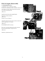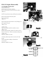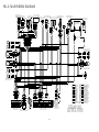
1
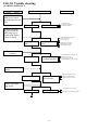
Kolpin Powersports
180cc Service
Manual
CONTENTS
FIG.-01
FIG.-02
FIG.-03
FIG.-04
FIG.-05
FIG.-06
FIG.-07
FIG.-08
FIG.-09
FIG.-10
FIG.-11
FIG.-12
FIG.-13
FIG.-14
FIG.-15
FIG.-16
FIG.-17
FIG.-18
FIG.-19
FIG.-20
FIG.-21
INFORMATION.……………………….…………….
VEHICLE INSPECTION………………………….......
OVERVIEW…………………………………….……..
FENDER..……………………………………...……...
FUEL &OIL TANK……………..……………………..
MUFFLER…………………………………………….
HANDLEBAR………………………………………...
ENGINE REMOVAL…….……………………………
TIRE AND RIM……………….………………………
FRONT BRAKE………………………………………
REAR BRAKE………………………………………...
SUSPENSION…………………………………………
SUSPENSION ARM& KNUCKLE…..……………….
REAR AXLE ASS’Y……...…………………………..
STEERING SHAFT…..…………….…………………
FRAME COMP………………………..………………
LIGHT………………………………..………………..
ENGINE DISASSEMBLY .……..…………………….
ELECTRIC SYSTEM……….………………………..
TROUBLE SHOOTING………………………………
MAIN WIRE DRAWING…………………………….
………………………………
………………………………
………………………………
………………………………
………………………………
………………………………
………………………………
………………………………
………………………………
………………………………
………………………………
………………………………
………………………………
………………………………
………………………………
………………………………
………………………………
………………………………
………………………………
………………………………
………………………………
1
6
18
19
22
23
24
26
27
28
30
32
33
34
35
36
37
39
68
73
85
FIG-01 INFORMATION
SAFETY
GASOLINE
Gasoline is extremely flammable and is explosive under certain condition. Do not smoke or allow sparks or
flames in your work area.
CARBON MONOXIDE
Never run the engine in a closed area. The exhaust contains poisonous carbon monoxide gas that may cause loss
of consciousness and lead to death.
BATTERY ELECTROLYTE
The battery electrolyte contains sulfuric acid. Protect your eyes, skin and clothing. If you come into contact with
the electrolyte, flush the area thoroughly with water. If you get the electrolyte in your eyes, flush with water and
contact a doctor immediately.
HOT PARTS
Engine and exhaust pipe become very hot and remain hot for one hour after the engine is run. Wear insulated
gloves before handling these parts.
USED ENGINE /GEAR OIL
Used engine oil and gear oil may cause skin disease after repeated contact with the skin for long periods. Keep out
of reach of children.
NOTES
All information, illustrations, directions and specifications included in this publication are base on the latest
product information available at the time of approval for printing.
No part of this publication may be reproduced without written permission.
1
FIG-01 INFORMATION
SPECIFICATIONS
TYPE
OVERLAND – 180CC
ENGINE TYPE
Air-Cooled 4-stroke, with Oil Cooler, Horizontal Stroke
CYLINDER NUMBER
1
DISPLACEMENT
169 cc
BORE STROKE
∮ 61×57.8mm
COMPRESSION RATIO
9.1:1
MAX. TORQUE
6.37 Nm@4403 rpm
CARBURETOR
MIKUNI 180
STARTING
Electric/ Kick back-up
LUBRICATE
Forced pressure and wet sump
LUBR. CAPABILITY
1 Liter
TRANSMISSION
Automatic (C.V.T V-belt system)
SUSPENSION
BRAKE
TIRE
FRONT
Single A-Arm
REAR
Single Swing Arm
FRONT
Drum
REAR
Disc
FRONT
21× 7- 10”
REAR
21× 10- 8”
OVERALL DIMENSION
1740×990×1060 mm
WHEELBASE
1065 mm
DRY WEIGHT
165 kg
FUEL
Unleaded Gasoline
FUEL CAPABILITY
8 Liter
Ignition
Capacitor Discharge
Air Cleaner
AE-9
*Specifications subject to change without notice.
2
FIG-01 INFORMATION
SERIAL NUMBER
The frame serial number is stamped on the front frame.
The engine number is stamped under the crankcase.
3
FIG-01 INFORMATION
TORQUE VALUES
STANDARD
5mm bolt and nut
6mm bolt and nut
8mm bolt and nut
10mm bolt and nut
12mm bolt and nut
5 N.m (3.5 lbs.ft)
10 N.m (7.2 lbs.ft)
22 N.m (16 lbs.ft)
35 N.m (25 lbs.ft)
55 N.m (40 lbs.ft)
ENGINE
Cylinder head nut
Spark plug
Cylinder head bolt
28 N.m (20.7 lbs.ft)
12 N.m (8.9 lbs.ft)
20 N.m (14.8 lbs.ft)
Alternator bolt
8 N.m (5.9 lbs.ft)
FRAME
Handlebar upper holder bolt
Throttle housing cover screw
Steering shaft nut
Steering shaft holder bolt
Wheel rim bolt
Tie rod lock nut
King pin nut
24 N.m (17.7 lbs.ft)
4 N.m (2.9 lbs.ft)
50 N.m (36.9 lbs.ft)
33 N.m (24 lbs.ft)
18 N.m (13.3 lbs.ft)
35 N.m (25.8 lbs.ft)
40 N.m (29 lbs.ft)
Handlebar lower holder nut
Front wheel bolt
Front axle nut
Front brake arm nut
Rear brake arm nut
Rear axle nut
Rear wheel bolt
Exhaust muffler mounting bolt
Engine hanger bolt
40 N.m (29.5 lbs.ft)
24 N.m (17.7 lbs.ft)
60 N.m (44 lbs.ft)
4 N.m (3.0 lbs.ft)
7 N.m (5.2 lbs.ft)
60 N.m (44.3 lbs.ft)
24 N.m (17.7 lbs.ft)
30 N.m (22.1 lbs.ft)
30 N.m (22 lbs.ft)
90 N.m (65 lbs.ft)
Rear axle holder bolt
Swing arm pivot nut
Rear shock absorber mounting nut
90 N.m (65 lbs.ft)
45 N.m (33 lbs.ft)
4
5
FIG-02. Vehicle Inspection
MAINTENANCE DATA
SPARK PLUG
Spark plug cap
Recommended spark plugs
Throttle lever free play:
Idle speed
Brake lever free play:
Drive chain slack
Front/rear tire size
Front/rear tire pressure
Toe-in
0.6-0.7mm
NGK C7HSA or CR7HSA
5-10mm
1800rpm
10~20mm
15-25mm
21x7-10” / 21x10-8”
3±0.3psi (0.15 kgf/cm2)
5±10mm
TORQUE VALUES
Spark plug
Tie-rod lock nut
12-19 N.m
35-43 N.m
ENGINE OIL
Viscosity:
SAE 15W-40
GEAR LUBRICATION OIL
Viscosity:
SAE 85W-140
6
FIG-02. Vehicle Inspection
MAINTENANCE SCHEDULE
The maintenance intervals in the follow table are based
upon average riding conditions. Riding
in unusually dusty areas requires more frequent
servicing.
Service Item
ENGINE OIL
GEAR OIL
FUEL FILTER
AIR VLEAN FILTER
ENGINE OIL
FILTER
CARBURETOR
SPARK PLUG
VALVE GAP
IGNITION TIMING
CHAIN
BATTERY
DRIVE BATTERY
CLUTCH
THROTTLE
OPERATE
TIRE PRESSURE
BRAKE SYSTEM
NUTS/BOLTS
A: Adjust
C: Clean
Initial Service
(First 30 hours)
R
R
Every 100 hours
Every 200 hours
Every 300 hours
R
R
R
R
C
I
C
A
A
A
I
I
I
I
Check before riding each time
Check before riding each time
T
I: Inspection
R: Replace
7
T: Tighten
FIG-02. Vehicle Inspection
FUEL TUBE
Inspect the fuel lines for deterioration, (a-1)
damage or leakage and replace if necessary.
(Photo 1)
THROTTLE OPERATION
1. Inspect for smooth lever operation, full opening and
automatic full closing in steering positions.
2. Inspect for deterioration, damage, cuts and nicks, or
kink in the throttle cable, replace it if necessary.
3. Check the throttle lever, free play should be not more
than 5-10 mm at the tip of the throttle lever. (a-1)
4. Disconnect the throttle cable at the upper end.
Lubricate the cable with commercially lubricant to
prevent premature wear.
(Photo 2)
THROTTLE CABLE ADJUSTMENT
Slide the rubber cap of the adjuster off the throttle
housing, loosen the lock nut and adjust the free play of
the throttle lever by turning the adjuster on the throttle
housing. Inspect the free play of the throttle lever. (a-1)
(Photo 3)
AIR CLEANER MAINTENANCE
1. Loosen the screw and remove the air cleaner from
carburetor. (a-1)
2. Disassemble the air cleaner cover and body.
3. Remove the air cleaner element and screen.
Install the new one. (a-2)
4. Assemble the air cleaner body and cover and
re-attach to the carburetor with screw.
(Photo 4,5)
8
FIG-02. Vehicle Inspection
SPARK PLUG
The spark plug is located at the front of the engine.
1. Disconnect the spark plug cap and remove the spark
plug (a-1)
2. Visually inspect the spark plug electrode for wear or
cranks in insulator. Replace if needed
3. The center electrode should have square edges and
the side electrode should have a constant thickness.
4. Discard the spark plug if there is apparent wear or if
the insulator is cracked or chipped.
5. Measure the gap with a wire-type feeler gauge and
adjust if necessary by carefully bending the side
electrode.
6. Check the sealing washer and replace with a new one
if damaged.
7. With the sealing washer attached thread the spark
plug in by hand to prevent cross threading. Tighten the
spark plug. TORQUE: 12-19 N-m
SPARK PLUG GAP: 0.6~0.7 mm
RECOMMENDED REPLACEMENT PLUG:
NGK CR7HSA
(Photo 6)
IDLE SPEED SETTING
1. Inspect and adjust the idle speed after all other engine
maintenance items have been performed and are
within specifications. The engine must be warm for
accurate idle speed inspection and adjustment.
2. Warm up the engine for about ten minutes and
connect a tachometer.
3. Turn the throttle stop screw as required to obtain the
specified idle speed. (a-1)
IDLE SPEED: 1700 ± 100 rpm
(Photo 7)
9
FIG-02. Vehicle Inspection
DRIVE CHAIN ADJUSTMENT
Stop ATV and shift transmission into neutral. Inspect
the chain slack midway between the sprockets. The
standard is 10-25 mm (5/8-1 inch).
If needed remove the chain protectives cover and adjust
the chain slack. (a-1)
(Photo 8)
Loosen the axle holder lock nut then adjust the drive
chain slack by turning the adjusting nut. Tighten the
axle holder lock nut. (a-1)
Torque = 90N.m (65 Ft. lbs)
(Photo 9)
When the drive chain becomes very dirty, it should be
removed, cleaned and lubricated with the specified
lubricant.
1. Clean the drive chain with kerosene and wipe it dry
2. Inspect the drive chain for possible wear or damage.
3. Replace the chain, if it is worn excessively or
damaged.
4. Inspect the sprocket teeth, if it has excessive wear or
damage, replace if needed.
5.Use a commercial chain lubricant to lubricate the
drive chain, replace and adjust the slack as described
above. (a-1)
(Photo 10)
10
FIG-02. Vehicle Inspection
FRONT BRAKE ADJUSTMANT
The front brake has two cables to control right and
left side brake simultaneously.
You could adjust the gap of the front brake (a-1).
(Photo 11)
Loosen the fix nut (a-1) and adjust the position of cable
to proper situation.
(Photo 12)
Inspect the front brake lever and cable for excessive
play or other damage.
Replace or repair if necessary.
Measure the free play of the brake lever at the end of
the lever. The standard is 10~20 mm.
Adjust the free play of the front brake lever by turning
the adjuster on the brake lever assembly.
The brake shoe uses an arrowhead on the front brake
plate to indicate pad condition.
When the arrowhead is beyond the wear limits shown,
the brake shoes need to be changed. (a-1)
(Photo 14)
REAR BRAKE ADJUSTMENT
Install the rear brake cable fixing nut set & adjust the
brake cable.
1. Spin the gap adjuster on the left lever to the shortest
position. (a-1)
2. Adjust the adjusting screw and keep the gap within
2-3 mm. (a-2)
(Photo 15,16)
11
FIG-02. Vehicle Inspection
REAR BRAKE ADJUSTMENT
Remove the rear brake locking nut set and the brake
cylinder mounting bolts (a-1)
(Photo 17)
The setup of the adjusting nut of the brake pump(a-1):
1. The brake pedal should be in the highest location
with the returning spring functioning correctly.
2. The adjusting nut changes the distance between the
brake master cylinder and the hydraulic
cylinder-driving rod. Make sure the nut touches the
surface of the rod and revolve back 1 turn (360˚).
Confirm the nut location and spin the rod until the
nut is locked (a-2).
(Photo 18,19)
NOTICE:
Do not over-adjust, it might result in the
brake pump malfunction and cause the brake to activate.
1. Remove any air in the brake line to prevent
the brake from losing power(a-1).
2. Open the brake oil tank (a-2) and loosen the drain
screw of the brake caliper without pumping the brake.
In normal operation the brake oil could drain
automatically; please try this for couple times for
confirmation. If it doesn’t work, adjustment of the brake
pump may be required.
(Photo 20,21)
NOTICE:
Verify oil amount is above the minimum level.
Press on the brake pedal or pull the brake lever several
times then hold pressure, release the drain screw and
lock it on immediately until no air bubbles are found in
the brake oil.
Be careful for splashing oil when bleeding the brakes.
12
FIG-02. Vehicle Inspection
REAR BRAKE FLUID REFILLING METHOD
1. Remove the oil tank cover (a-1).
2. Refill with the recommended DOT-3 brake fluid until
the level reaches the upper limit.
(Photo 22)
CAUTION
Be careful when filling the brake oil tank to
to avoid spilling the oil
13
FIG-02. Vehicle Inspection
FRONT SUSPENSION
1. Check the R. and L. side suspension, the front
suspension should be adjusted to the same preload (a-1).
2. Inspect the shocks for oil leakage; if any is present,
replace shocks.
3. Check the welding of frame bracket, which is
connected to front suspension.
4. Also, check the swing arm for cracks or dents (a-2).
(Photo 23)
REAR SUSPENSION
1. Check the rear suspension for proper spring preload
(a-1). Inspect the shock for oil leakage; if any is present,
replace shock
2. Check the welding of frame bracket that connects
with rear shock and the condition of swing arm.
(Photo 24)
MANUAL CHOKE CABLE
There is an adjustment screw under the master cylinder
to control the amount of choke opening for proper
starting (a-1).
(Photo 25)
WHEELS AND TIRES
Inspect the tire surface for cuts, nails or other sharp
objects. (a-1).
Check the tire pressure at cold tire conditions.
The standard tire pressure is 3psi. (0.15kgf/cm2 )
(Photo 26)
14
FIG-02. Vehicle Inspection
STEERING SYSTEM
Check the free play of the steering shaft with the front
wheels turned straight ahead. When there is excessive
play, inspect the tie-rod, kingpin bushing and ball joint.
(a-1).
(Photo 27)
STEERING SHAFT HOLDER BUSHING
Remove the front fender.
Remove the steering shaft holder and check the steering
shaft bushing for wear or damage.
If the bushing is worn or damaged, replace the bushing.
Grease the steering shaft bushing and install the parts in
the reverse order of removal. (a-1)
(Photo 28)
Torque: steering shaft holder bolt: 33N.m ( 24 Ft. lbs)
TOE-IN
Park the vehicle on level ground with the front wheels
facing straight ahead.
Mark the centers of the tires to indicate the axle center
height.
Measure the distance between the marks.
Carefully move the vehicle back, let the wheels turn
180° so the marks on the tires are aligned with the axle
center height.
(Photo 29)
Measure the distance between the marks.
Calculate the difference in the front and rear
measurements.
(Photo 30)
Toe-in: 5±10 mm
If the toe-in is out of standard, adjust it by changing the
length of the tie-rods equally by turning the tie-rod
while holding the ball joint.
Tighten the lock nuts (a-1)
Torque: 35-43 N.m
(Photo 31)
15
FIG-02. Vehicle Inspection
GEAR OIL MAINTENANCE
Gear oil needs to be changed every 200 hours.
There is a gear oil drain hole bolt at the rear of the
engine.
1. Unscrew this drain hole bolt and let the dirty oil flow
out, catching the oil in a proper container for later
disposal.
2. Reinstall the drain hole bolt and tighten.
3. Fill with new gear oil through the oil fill hole located
on the engine case beside the gearbox.
(Photo 32)
LUBRICATE
There is a grease valve on the R. and L. suspension arm
and swing arm sub ass’y (a-1).
Please lubricate the grease frequently on the grease
valve.
(Photo 33)
16
0.6~0.7
mm
17
FIG-03. Overview
Parts Description
01. HANDLE BAR COVER
02. FRONT FENDER CARRIERS
03. HEAD LIGHT ASS’Y
04. POSITION LIGHT ASS’Y
05. MASTER CYLINDER SUB(L)
06. FRONT METAL RACK
07. BUMPER
08. FRONT SUSPENSION
09. RIGHT LEVER ASS'Y
(Including parking brake)
10. L. SWITCH ASS'Y
11. MAIN SWITCH ASS'Y
12. NEUTRAL INDICATOR
13. REVERSE INDICATOR
14. FUEL GAUGE ASS'Y
15. TRANSMISSION LEVER
16. REAR SUSPENSION
17. SEAT
18. TAIL LIGHT ASS’Y
19. REVERSE LIGHTS
20. REFLECTOR
21. REAR METAL RACK
22. TRAILER HITCH MOUNT
18
FIG-04. Fender
BUMPER
Loosen the bolts (a-1) and Remove the bumper (a-2)
from the frame body
(Photo 1)
FRONT METAL RACK
Loosen the bolts (a-1)
and Remove the front metal rack (a-2)
from the frame body
(Photo 2)
REAR METAL RACK
Loosen the screws (a-1)
Loosen the bolts (a-3)
Remove the rear rack bracket (a-2)
Loosen the bolts (a-3)
Remove the rear metal rack (a-4)
(Photo 3)
Note:
Refer to the preceding disassembly instructions for
re-assembly.
19
FIG-04. Fender
FRONT FENDER COVER
Loosen the screws (a-1)
Remove the front fender cover (a-2)
(Photo 4)
BUMPER COVER
Loosen the screws (a-1)
Loosen the screws (a-2)
Take off the main wire connect with the lights wire (a-3)
Remove the front fender cover (a-4)
(Photo 5)
LICENSE PLATE
Loosen the screws (a-1)
Loosen the screws (a-2)
Take off the main wire connect with the lights wire (a-3)
Remove the license plate (a-4)
(Photo 6)
SEAT ASS'Y
Pull the “Seat Release Bar” to take off the seat. (a-1)
This seat release bar is under the right side of the rear
fender. Remove the seat ass’y
(Photo 7)
FRONT FENDER
Loosen the screws (a-1)
Loosen the hex bolt with plain washer (a-2)
Take off the fuel tank cap
Remove the front fender (a-4)
(Photo 8)
FRONT FENDER
Loosen the screws (a-1)
Loosen the hex bolt with plain washer (a-2)
Remove the front fender (a-3)
(Photo 8)
CAUTION
1. The battery and the toolbox are put under the seat.
20
FIG-04. Fender
FOOTREST
Loosen the bolts (a-1)
Remove the footrest ass’y (a-2)
(Photo 10)
Note:
Refer to the preceding disassembly instructions for
re-assembly.
21
FIG-05. Fuel & Oil Tank
FUEL TANK
Loosen the bolts (a-1)
Take off the main wire connect with the fuel gauge wire
(a-2)
Loosen the bolts (a-3)
Remove the petcock ass’y, vacuum shut-off (a-4)
Remove the fuel tube (a-5) with the fuel filter ass’y(a-6)
Remove the air tube (a-7)
Remove the fuel tank (a-8) leave the frame body
(Photo 11,12)
CAUTION
1. There are rubbers on the frame body to reduce the
vibration and to protect the fuel tank.
2. There is a breather tube in the fuel cap.
Note:
Refer to the preceding disassembly instructions for
re-assembly.
22
FIG-06. Muffler
MUFFLER
Loosen the bolts (a-1) and make it connected to the
cylinder (a-2).
(Photo 13)
CAUTION
1. The muffler is hot during operation.
2. Do not touch the muffler or the heat shields.
3. Please check the gasket of muffler before mounting
the muffler.
Loosen the bolts (a-1) of the muffler (a-2)
on the frame body (a-3).
(Photo 14)
Note:
Refer to the preceding disassembly instructions for
re-assembly.
23
FIG-07. HANDLEBAR
HANDLE BAR COVER
Loosen the screws (a-1)
Remove the head light cover (a-2)
Take off the main wire connect with the head light wire
(Photo 15)
Remove the fuel gauge ass’y (a-1)
Loosen the nut remove the neutral indicator (a-2)
Loosen the nut remove the reverse indicator (a-3)
Remove the main switch clip and take off the main
switch (a-4)
(Photo 16)
Loosen the bolts (a-1)
Remove the protect cover mounting plate (a-2)
(Photo 17)
24
FIG-07. HANDLEBAR
REAR BRAKE CABLE
Remove the rear brake cable (a-1)
(Photo 18)
FRONT BRAKE CABLE
Remove the R. and L. front brake cable (a-1)
(Photo 19)
THROTTLE CABLE
Right lever ass’y loosen the screws (a-1)
open the cover and mount the throttle cable (a-2)
in the box
(Photo 20)
CAUTION
1. Smear grease on the throttle wire before mounting it
in the throttle box.
2. There is a park brake on the R. level.
3. It is design for safety assurance. When the vehicle
stopped on the slope ground, please operate the park
brake.
MANUAL CHOKE WIRE
Remove the manual choke wire on the L. Switch (a-1)
(Photo 21)
The L. Switch includes the engine start switch (a-2),
Horn switch (a-3)
Engine stop switch (a-4),
Headlight (high/low beam) switch (a-5).
(Photo 21)
HANDLE BAR CLAMP COVER
Loosen the bolts (a-1)
Remove the handle bar ass’y (a-2)
(Photo 22)
Note:
Refer to the preceding disassembly instructions for
re-assembly.
25
FIG-08. Engine Disassembly
DRIVE CHAIN ASS'Y
Take off the chain master link set (a-1)
Remove the drive chain (a-2)
(Photo 23)
TRANSMISSION ASS'Y
Loosen the bolts (a-1)
Remove the shifter plate (a-2) with the reverse cut-out
switch and reverse indicator switch
Remove the transmission lever (a-3)
Remove the transmission fork link (a-4)
(Photo 24)
RADIATOR
Loosen the bolts (a-1) on the frame body.
Loosen the bolts (a-2) on the oil hose outlet.
Remove the radiator (a-3)
(Photo 25)
WIRE
Take off the main wire connect with the generator ass’y
wire (a-1) and starting motor ass’y wire (a-2)
(Photo 26)
ENGINE
Loosen the front bolts (a-1)
Loosen the rear bolts (a-2)
Remove the engine bracket plate (a-3)
Remove the engine (a-4)
(Photo 27)
Note:
The detailed Engine disassembling to refer to FIG-18
Refer to the preceding disassembly instructions for
re-assembly.
26
FIG-09. Tire and Rim
FRONT WHEEL ASS’Y
Take off the rubber cap (a-1) and cotter pin (a-2)
Loosen the insert lock nut (a-3)
Remove the washer (a-4) and plain washer (a-5)
(Photo 28,29)
FRONT WHEEL ASS’Y
Loosen the bolts (a-1)
Remove the wheel tire (a-2) and rim (a-3)
Remove the front brake drum (a-4)
(Photo 30)
FRONT TIRE SPECIFICATIONS
Front tire -- 21*7.0-10"
REAR WHEEL ASS’Y
Take off the rubber cap (a-1) and cotter pin (a-2)
Loosen the insert lock nut (a-3)
Remove the washer (a-4) and plain washer (a-5)
(Photo 31,32)
REAR WHEEL ASS’Y
Loosen the nylon insert lock nuts (a-1)
Remove the wheel tire (a-2) and rim (a-3)
Remove the shaft connecter (a-4)
(Photo 33)
REAR TIRE SPECIFICATIONS
Rear tire -- 21*10. 0-8"
CAUTION
1. When the cotter pin is damaged, it must be changed
to a new one.
2. The tire has a tread arrow, when assembled the arrow
must point to the front
Note:
Refer to the preceding disassembly instructions for
re-assembly.
27
FIG-10. Front Brake
BRAKE SYSTEM
Brake Parts & Location
.
28
FIG-10. Front Brake
FRONT BRAKE PLATE ASS'Y
Remove the front brake cable (a-1) with the front brake
arm put in the up side hole (a-2).
Remove the front brake plate ass’y (a-3)
Remove the front brake shoe comp (a-4).
(Photo 34,35)
CAUTION
1. Brake pads must be changed when the friction
material is worn out (see indicator on brake face).
2. Assemble the front brake plate ass’y on the knuckle
with the fixed position.
FRONT BRAKE DRUM
There is oil seal (a-1) front brake plate
There is bearing (a-2) on the brake drum.
Please check these parts when the brake drum is
mounted or dismounted.
(Photo 36)
Note:
Refer to the preceding disassembly instructions for
re-assembly.
29
FIG-11. Rear Brake
MASTER CYLINDER SUB
Brake fluid level must be below the maximum level
Fill with fluid when the level is below the “min” line
(a-1)
(Photo 37)
CALIPER ASS'Y
Check the brake pad kit, when the friction material is
worn away, pads must be changed to a new set (a-1)
(Photo 38)
Loosen the bolts (a-1)
Remove the caliper ass’y (a-2)
Loosen the bolts (a-3) on the caliper
Remove the brake pad kit (a-4)
(Photo 39)
CAUTION
1. When changing the brake pad kit, be careful not to
allow grease to touch the brake pad kit
BRAKE HOSE
To let out the brake oil
Loosen the bolts (a-1)
Remove the brake hose (a-2) and plain washer (a-3)
(Photo 40)
CAUTION
1. When changing the brake hose, replace the plain
washer if damaged.
30
FIG-11. Rear Brake
RIGHT FOOTWELL BOTTOM BOARD
Loosen the bolts (a-1)
Remove the right footwell bottom board (a-2)
(Photo 41)
REAR BRAKE CABLE FIXED HOLDER
Loosen the nuts (a-1) on the rear brake cable (a-2)
(Photo 42)
Loosen the bolts (a-1)
Remove the switch spring (a-2)
Remove the rear brake cable fixed holder (a-3)
Remove the wave washer (a-4)
(Photo 43)
HYDRAULIC CYLINDER LEVER
Loosen the bolts (a-1)
Remove the master cylinder (a-2)
Remove the hydraulic cylinder lever (a-3)
Remove the hydraulic parallel pin (a-4)
Remove the hydraulic cotter pin (a-5)
(Photo 44,45)
PENDANT BRAKE LEVER
Remove the spring (a-1)
Remove the front pedal brake connected cable (a-2)
Remove the pendant brake lever (a-3)
(Photo 46)
Note:
For detailed Rear brake disassembling refer
to FIG-20
Refer to the preceding disassembly instructions for
re-assembly.
31
FIG-12. Suspension
FRONT SUSPENSION
The front suspension is mounted on the frame (a-1)
and suspension arm (a-2).
Loosen the bolts (a-3) and nuts (a-4)
Remove the front suspension (a-5)
(Photo 47)
CAUTION
1.The front suspension of the 50cc/100cc can be
adjusted to the proper damper according driver’s
preference.
REAR SUSPENSION
The rear suspension is mounted on the frame (a-1)
and swing arm sub ass’y (a-2).
Loosen the bolts (a-3)
Remove the rear suspension (a-4)
(Photo 48)
CAUTION
The rear suspension of the 50cc/100cc can be adjusted
to the proper damper according drive’s preference
Note:
Refer to the preceding disassembly instructions for
re-assembly.
32
FIG-13. Suspension Arm
KNUCKLE
Take off the cotter pin (a-1)
Loosen the nut (a-2)
Remove the steering tie-rod ass’y (a-3)
(Photo 49)
Take off the cotter pin (a-1)
Loosen the insert lock nut (a-2)
Remove the washer (a-3)
Remove the knuckle (a-4)
(Photo 50)
SUSPENSION ARM
Loosen the bolts (a-1) with the suspension (a-2)
Loosen the bolts (a-3) and nuts (a-4) with the frame
body (a-5)
(Photo 51)
CAUTION
1. The suspension arm marked “R” is for the right side.
2. The suspension arm marked “L” is for the left side.
3. The knuckles are marked “R” or “L”, please pay
attention the differences while mounting.
4. Before mounting knuckle, please smear grease on the
knuckle.
5. Mount the knuckle on the suspension arm and tighten
the nut and put on the cotter pin.
6. Please check the refill grease on it frequently.
33
FIG-14. Rear Axle Ass’y
PROTECTIVE COVER
Loosen the bolts (a-1)
Remove the protective cover (a-2)
(Photo 52)
REAR AXLE
Loosen the nuts (a-1)
Remove the washer (a-2) and brake plate ass’y (a-3)
Remove the rear axle (a-4)
Remove the final drive sprocket ass’y (a-5)
(Photo 53)
REAR AXLE FIX SEAT ASS'Y
Loosen the bolts (a-1)
Remove the rear axle fix seat ass’y (a-2)
Remove the adjuster chain (a-3) and nuts (a-4)
(Photo 54)
SWING ARM SUB ASS'Y
Loosen the bolts (a-1) and nut (a-2)
Remove the swing arm sub ass’y (a-3)
Remove the swing arm spacer tube
Remove the rubber sleeve
(Photo 55)
CAUTION
1. Before mounting swing arm, please smear grease on
the swing arm spacer tube.
Note:
Refer to the preceding disassembly instructions for
re-assembly.
34
FIG-15. Steering Shaft
STEERING SHAFT
Turn on the spring washer (a-1)
Loosen the bolts (a-2)
Remove the spring washer (a-3) and cable fix seat (a-4)
Remove the steering shaft hold (a-5)
Remove the space ring steering shaft oil seal (a-6)
(Photo 56)
CAUTION
1. Before mounting steering shaft, please smear grease
on the steering shaft oil seal.
Take off the cotter pin (a-1)
Loosen the nut (a-2)
Remove the steering tie-rod ass’y (a-3)
Take off the cotter pin (a-4)
Loosen the nut (a-5)
Remove the steering shaft ass’y (a-6)
(Photo 57)
CAUTION
1. Check that the steering can be turned smoothly after
the steering shaft is mounted.
2. Check the oil seals and bearings on the bottom of the
steering shaft.
3. Check those parts while the steering is dismounted or
mounted.
4. Check the steering with the steering lock for normal
movement.
35
FIG-16. Frame Comp
FRAME COMP
Take off the o-ring (a-1)
Remove the steering bearing seat (a-2)
(Photo 58)
Note:
Refer to the preceding disassembly instructions for
re-assembly.
36
FIG-17. Light
HEAD LIGHT ASS’Y
Loosen the screws (a-1)
Remove the head light ass’y (a-2)
(Photo 59)
Turn off the light cover (a-1)
Remove the position light bulb ass’y (a-2)
(Photo 60)
CAUTION
1. The position light bulb specifications is 12V 10W
2. The head light bulb specifications is 12V 20W
TAIL LIGHT ASS’Y
Loosen the screws (a-1)
Remove the tail light cover (a-2)
(Photo 61)
CAUTION
1. When change the bulb only loosen the screws and
then open the cover.
2. The tail light bulb specifications is P21/5W
REFLECTOR
Loosen the nuts (a-3)
Remove the reflector (a-4)
(Photo 61)
REVERSE INDICATOR
Turn off the light cover (a-1)
Remove the reverse indicator bulb ass’y (a-2)
(Photo 62)
CAUTION
1. The position light bulb specifications is 12V 10W
37
0.6~0.7
mm
38
FIG-18. Engine Disassembly
ENGINE SHOULD ONLY BE REMOVED IN THE
CONDITIONS OF NECESSARY REPAIRS OR
ADJUSTMENT TO THE TRANSMISSION AND
COMBUSTION SYSTEM ONLY!
ENGINE REMOVAL
Remove the front, rear rack, and handle bar.
Remove the footrest.
Remove the spark plug cap from the spark plug.
Remove the exhaust muffler.
Disconnect the carburetor cable by unscrewing two
screws on top of the carburetor.
Disconnect the wire connectors. There are three
connectors for carburetor auto-choke, starter motor and
generator respectively.
Remove the engine hanger bolts over the engine.
Remove the engine and air cleaner together.
ENGINE REPLACEMENT
Engine installation is essentially the reverse order of
removal.
The torque of engine hanger bolt is 30 Nm
Route the wires and cable properly in reverse order of
removal.
39
FIG-18. Engine Disassembly
LUBRICATION
SERVICE INFORMATION
GENERAL
This section describes inspection and replacement of the
engine oil, oil filter screen and assembly of the oil
pump.
Fill the oil pump with clean oil when reassembling the
pump.
SPECIFICATIONS
Engine Oil Capacity
Engine Oil Recommendations
0.8-1.0 Liters
Viscosity: (SAE 15W-40)
API Service classification: SF-SG
OIL PUMP
STANDARD
Cover-to-rotor clearance
Rotor tip clearance
End clearance
SERVIC
----------------0.01-0.10
TORQUE VALUE
Oil Drain Bolt
20~30 n-m (2.0~3.0 kg-m)
TROUBLE SHOOTING
Oil level too low / high oil consumption
Normal oil consumption.
External oil leaks.
Oil not changed often enough.
Worn piston rings.
Faulty head gasket.
Oil contamination
Worn piston rings.
Faulty head gasket.
Oil or filter not changed often enough.
40
LIMIT
0.12
0.12
0.2
FIG-18. Engine Disassembly
LUBRICATION
ENGINE OIL LEVEL
Place the engine on the level plane.
Check the oil level with the oil level gauge, but do not
screw it in when making this check.(a-1)
(Photo 1)
OIL LEVEL GAUGE
Add the recommended oil up to the upper level if the oil
level is below or near lower level line on the gauge.
(Photo 2)
41
FIG-18. Engine Disassembly
LUBRICATION
ENGINE OIL & FILTER CHANGE
Remove the oil filter cap and the oil drain bolt. (a-1)
(Photo 3)
NOTE: drain the oil while the engine is warm to ensure
complete draining.
Remove the oil filter cap (a-1), spring (a-2) and oil filter
screen. (a-3)
Check the O-ring for damage or fatigue. (a-4)
Install a new oil filter screen and spring then install the
cap.
(Photo 4)
Install a new oil filter screen and spring then install the
cap.
Install the oil drain bolt with sealing washer.
TORQUE: 20~30 n-m (2.0~3.0 kg-m)
Fill the crankcase with recommended oil.
Install the oil filter cap. (a-1)
(Photo 5)
ENGINE OIL CAPACITY: 1.2 liter at draining.
Install the oil level gauge.
Start the engine and let it idling for 2 or 3 minutes.
Stop the engine and check that the oil level at the upper
line on the gauge. Make sure there are no oil leaks.
42
FIG-18. Engine Disassembly
OIL PUMP REMOVAL
FAN COVER ASS’Y
Loosen the screw (a-1),
Remove the fan cover ass’y (a-2),
(Photo 6)
FAN
Loosen the screw (a-1),
Remove the cooling fan composition (a-2),
(Photo 7)
GENERATOR ASS'Y
Loosen the nut (a-1)
Use the special tool Remove the generator face flywheel.
(a-2)
Loosen the bolts
Remove the stator comp.
(Photo 8)
RIGHT CRANKCASE COVER
Loosen the bolts (a-1)
Remove the right crankcase cover. (a-2)
(Photo 9)
STARTING CLUTCH ASS'Y
Loosen the nut (a-1)
Remove the gear comp starting clutch (a-2)
Remove the starting clutch ass’y.
(Photo 10)
43
FIG-18. Engine Disassembly
OIL PUMP REMOVAL
OIL PUMP
Loosen the bolts (a-1)
Remove the oil separator. (a-2)
(Photo 11)
Remove the oil pump chain (a-1)
Remove the oil pump drive (a-2)
(Photo 12)
Loosen the bolts (a-1)
Remove the oil pump ass’y (a-2)
(Photo 13)
Note:
Refer the foregoing disassembly procedures to
re-assemble.
44
FIG-18. Engine Disassembly
OIL PUMP REMOVAL
DISASSEMBLE THE OIL PUMP
INSPECTION
Measure the oil pump rotor-to-body clearance.
(Photo 14,15)
SERVICE LIMIT: 0.12 mm
Install the oil pump shaft and measure the pump
clearance.
(Photo 16)
SERVICE LIMMIT: 0.12 mm.
Remove the oil pump shaft and measure the pump and
clearance.
(Photo 17)
SERVICE LIMMIT: 0.2 mm.
Install the outer rotor, inner rotor and oil pump shaft
onto the body.
(Photo 18)
NOTE: Pour a drop of clean engine oil inside the oil
pump
45
FIG-18. Engine Disassembly
CYLINDER HEAD / VALVES
SERVICE INFORMATION
GENERAL
This section describes the maintenance of cylinder head,
valves, camshaft and associated parts
The engine must be removed from the frame to service
cylinder head.
Camshaft lubrication oil is fed to the cylinder head
through an oil orifice in the engine case
Before installing the cylinder head be sure the orifice is
not clogged and the gasket, O-ring and dowel pins are
in place.
SPECIFICATIONS
ITEM
Cylinder compression
Cam lobe height
Rocker arm I.D.
Rocker arm shaft O.D.
Valve spring free length
Valve stem O.D.
Valve guide I.D.
Stem-to-guide clearance
Valve seat width
IN
EX
STANDARD
12±0.5 kg/cm2
25.965/27.195
25.810/27.20
10.000-10.018
9.972-9.987
32.3
35.0
IN
EX
IN/EX
IN
EX
IN
EX
4.975-4.990
4.955-4.970
5.000-5.012
0.010-0.037
0.030-0.057
1. 0
1.0
IN
EX
SERVICE LIMIT
--------25.57/26.7
25.40/26.80
10.10
9.91
31.2
34.1
TORQUE VALUES
Cylinder head bolts
Camshaft holder flange nuts
Tappet adjusting nut
8~12 n-m (0.8~12 kg-m)
20~24 n-m (2.0~2.4 kg-m)
9~12 n-m (0.9~1.2 kg-m)
46
4.90
4.90
5.30
0. 08
0.10
1. 8
1.8
FIG-18. Engine Disassembly
CYLINDER HEAD / VALVES
TROUBLE SHOOTING
Engine top-end problems usually affect engine
performance. These problems can be diagnosed by a
compression test, or by tracing engine noise to the top
end with a sounding rod or stethoscope.
Low compression valve
Incorrect valve adjustment.
Worn or damaged valve seats.
Burned or bent valve.
Incorrect valve timing.
Weak valve spring.
Cylinder head
Leaking or damaged head gasket.
Warped or cracked cylinder head.
Faulty cylinder or piston
Excessive noise
Incorrect valve adjustment
Sticking valve or broken valve spring.
Worn or damaged rocker arm or camshaft.
Worn or damaged cam chain.
Worn or damaged cam chain tensioned.
Worn cam sprocket teeth.
Excessive smoke
Damaged valve stem seal.
Faulty cylinder or piston rings.
47
FIG-18. Engine Disassembly
CYLINDER HEAD / VALVES
CYLINDER HEAD ASS’Y REMOVAL
SHROUD ASS’Y
Loosen the bolts (a-1)
Remove the carburetor overflow tube
Remove the intake manifold
Loosen the bolts
Remove the shroud
(Photo 19)
LIFTER TENSIONER LIFTER
Relax the cam chain adjuster screw. (a-1)
Remove the screw and O-ring and tighten the cam
chain adjusting bolt with clockwise direction. (a-2)
(Photo 20)
CYLINDER HEAD COVER ASS'Y
Loosen the bolts (a-1)
Remove the cylinder head cover ass’y (a-2)
(Photo 21)
COTTER VALVE
Remove the nuts and washers (a-1)
Remove the cotter valve (a-2)
Remove the camshaft holder and dowel pins.
(Photo 22)
Relax the camshaft gear from cam chain and remove the
camshaft.
(Photo 23)
48
FIG-18. Engine Disassembly
CAMSHAFT COMP
INSPECTION
Inspect the cam lobes surface and height of cam lobes
for wear or damage. (a-1)
(Photo 24)
SERVICE LIMIT:
IN:25.57/26.18 mm
EX:25.41/26.02 mm
Inspect the camshaft and bearings for wear or damage
and replace them if necessary.
(Photo 25)
Screw a 5 mm bolt into the rocker arm shaft threaded
end and pull on the bolt to remove the shafts and rocker
arms.
(Photo 26)
Inspect the camshaft holder, rocker arms and rocker arm
shafts for wear or damage.
(Photo 27)
Measure the I.D. of each rocker arm. (a-1)
SERVICE LIMIT: 10.10 mm
Measure the O.D. of each rocker arm shaft. (a-2)
SERVICE LIMIT: 9.91 mm
(Photo 28)
49
FIG-18. Engine Disassembly
CYLINDER HEAD REMOVAL
Remove the flange bolts and cylinder head
(Photo 29)
Remove the cylinder head gasket and dowel pins
(Photo 30)
Remove the cam chain guide
(Photo 31)
50
FIG-18. Engine Disassembly
CYLINDER HEAD DISASSEMBLY
Remove the valve cotters, spring retainers and valve
springs with a valve spring compressor.
(Photo 32)
INSPECTION
Clean off all carbon deposits from the combustion dome
and check the spark plug hole and valve area for cracks
(Photo 33)
Measure the cylinder head diagonally for warp with a
straight edge and feeler gauge.
(Photo 34)
Measure the free length of the inner and outer valve
springs.
(Photo 35)
SERVICE LIMITS: Inner 31.2 mm
Outer 34.1 mm
Inspect each valve stem for turning, burning, scratches
or abnormal wear.
Check the valve for movement in the guide.
(Photo 36)
Measure and record each valve stem O.D.
SERVICE LIMITS: 4.90 mm
Measure and record the valve guide I.D.
SERVICE LIMITS: IN / EX 5.30 mm
Calculate the stem-to-guide clearance.
SERVICE LIMITS: IN 0.08 mm
EX 0.10 mm
NOTE: If the stem-to-guide clearance exceeds the
service limits, determine if a new guide with standard
dimensions would bring the clearance within tolerance.
If so, replace guides as necessary and ream to fit. If the
valve guide is replaced, the valve seat must be ground.
51
FIG-18. Engine Disassembly
CYLINDER HEAD ASS’Y
Lubricate each valve stem with oil.
Insert the valves into the guides.
Install the valve springs, retainers and the cotters.
(Photo 37)
NOTE: To prevent loss of tension, don’t compress the
valve springs more than necessary.
INSTALLATION
Install the new gasket and dowel pins.
(Photo 38)
Install the cam chain guide.
(Photo 39)
Install the cylinder head.
(Photo 40)
CAMSHAFT ASS’Y INSTALLATION
Install the rocker arms and rocker arm shafts into the
camshaft holder.
(Photo 41)
Align the “T” mark on the flywheel with the index mark
on the alternator cover by turning the flywheel
counter-clockwise.
(Photo 42)
52
FIG-18. Engine Disassembly
CYLINDER HEAD ASS’Y
CAMSHAFT ASS’Y INSTALLATION
Position the camshaft gear with cam chain so that its “I”
mark aligns with the cylinder head surface and the
circle hole towards the front.
(Photo 43)
Install the dowel pins and camshaft holder.
Tighten the washers and nuts
(Photo 44)
Torque: 20 n-m (2.0 kg-m)
Adjust the clearance between the rocker arm and valve
stem by applying a feeler gauge.
(Photo 45)
STANDARD VALVE: 0.08 mm
Relax the cam chain-adjusting bolt with clockwise
direction and install the o-ring and screw.
(Photo 46)
Install the cylinder head cover.
53
FIG-18. Engine Disassembly
CYLINDER AND PISTON
SERVICE INFORMATION
GENERAL
Camshaft lubrication oil is fed to the cylinder head
through an oil orifice in the cylinder head and engine
case. Before installing the cylinder head be sure the
orifice is not clogged and the gasket, O-ring and dowel
pins are in place.
SPECIFICATION
ITEM
Cylinder
STANDARD
52,400-52,410/
61,730-61,740
SERVICE LIMIT
52.50/
61.830
Taper
----------
0.10
Out of round
----------
0.10
Warp across top
----------
0.10
I.D.
Piston
Piston O.D.
52,370-52,390
61,700-61,720
52,3/
61,63
Piston pin
Piston pin bore
15.002-15.008
15.04
Piston rings
Piston pin O.D.
14.994-15.000
14.960
0.002-0.014
0.02
TOP
0.015-0.050
0.12
SECOND
0.015-0.050
0.12
Groove Clearance
TOP/SEC
0.10-0.25
0.5
Piston ring end gap
OIL
0.2-0.7
----------
Cylinder-to-piston clearance
0.0005-0.1025
0.1
Connecting rod small end I.D.
15.010-15.028
15.06
Piston-to-pin clearance
Piston ring
TORQUE VALUES
Cylinder head bolts
Camshaft holder flange nuts
Tappet adjusting nut
8~12 n-m (0.8~1.2 kg-m)
20~24 n-m (2.0~2.4 kg-m)
9~12 n-m (0.9~1.2 kg-m)
54
FIG-18. Engine Disassembly
CYLINDER AND PISTON
TROUBLESHOOTING
Low or unstable compression
Worn cylinder or piston rings.
Overheating
Excessive carbon build-up on piston or combustion
chamber wall
Knocking or abnormal noise
Worn piston and cylinder.
Excessive carbon build-up.
Excessive smoke
Worn cylinder, piston, or piston rings.
Improper installation of piston rings
Scored or scratched piston or cylinder wall
Damaged valve stem seal.
55
FIG-18. Engine Disassembly
CYLINDER AND PISTON
CYLINDER REMOVAL
Remove the cylinder head.
(Photo 47)
Remove the cylinder.
(Photo 48)
Remove the cylinder gasket and dowel pins
(Photo 49)
Clean off any gasket materials from the cylinder
surface.
(Photo 50)
NOTE: Be carefully not to damage the gasket surface.
56
FIG-18. Engine Disassembly
CYLINDER AND PISTON
PISTON REMOVAL
Stuff a shop towel into the crankcase.
Remove the piston pin clip with needle nose pliers.
(Photo 51)
NOTE: Do not allow the clip to fall into the crankcase.
Remove the piston pin from the piston
Remove the piston.
(Photo 52)
Spread each piston ring and remove it by lifting up at a
point opposite the gap
(Photo 53,54)
INSPECTION
Inspect the cylinder walls for scratches or wear
(Photo 55,56)
Measure and record the cylinder I.D. at three levels in
both an X and Y-axis. Take the maximum reading to the
cylinder wear.
SERVICE LIMITS: 0.10 mm
Calculate cylinder taper at three levels in an X and
Y-axis
Take the maximum reading to determine the
out-of-round
SERVICE LIMITS: 0.10 mm
57
FIG-18. Engine Disassembly
CYLINDER AND PISTON
INSPECTION
Inspect the top of the cylinder for warp
(Photo 57)
SERVICE LIMITS: 0.10 mm
PISTON / PISTON RING INSPECTION
Measure the piston ring-to-groove clearance.
(Photo 58)
SERVICE LIMITS: TOP 0.12 mm
SECOND 0.12 mm
Inspect the piston for wear or damage.
Insert each piston ring into the cylinder and measure the
ring end gap.
(Photo 59,60)
NOTE: Push the rings into the cylinder with the top of
the piston to be sure they are squarely set in the
cylinder,
SERVICE LIMITS: TOP 0.5 mm
SECOND 0.5 mm
Measure the piston pin O.D.
(Photo 61)
SERVICE LIMIT: 14.960 mm
Measure the piston pin O.D.
(Photo 62)
SERVICE LIMIT: 15.04 mm
58
FIG-18. Engine Disassembly
CYLINDER AND PISTON
PISTON / PISTON RING INSPECTION
Calculate the piston-to-piston pin clearance.
(Photo 63)
SERVICE LIMITS: 0.02 mm
Measure the connecting rod small end I.D.
(Photo 64)
SERVICE LIMITS: 15.06 mm
PISTON &PISTON RING INSTALLATION
Clean the piston ring grooves thoroughly and install the
piston ring with the marks facing up.
NOTE: Don’t interchange the top and second rings to
avoid piston and piston ring damage during installation.
Space the piston ring end gaps 120 degrees apart
(Photo 65)
PISTON INSTALLATION
Install the piston with it’s “IN” mark on the intake valve
(Photo 66)
Install the piston pin with new pin clips.
Do not align the piston pin clip end gap with the piston
cutout.
(Photo 67)
NOTE: do not allow the clip to fall into the crankcase.
59
FIG-18. Engine Disassembly
CYLINDER AND PISTON
CYLINDER INSTALLATION
Clean any gasket material from the crankcase surface.
(Photo 68)
NOTE: Be carefully not to damage the gasket surface.
Install the dowel pins a new gasket.
Coat the cylinder bore and piston rings with engine oil
and install the cylinder.
(Photo 69,70)
NOTE: Avoid piston rings damage cylinder bore during
installation. Do not allow the cam chain fall into the
crankcase.
Install the cylinder head.
(Photo 71)
60
FIG-18. Engine Disassembly
TRANSMISSION & KICK STARTER
SERVICE INFORMATION
If the drain tube ass’y fills with water, the tube should
be drained.
SPECIFICATIONS
ITEM
Driven the width
Weight roller O.D.
Movable drive face I.D.
Drive face collar I.D.
Drive face boss O.D.
Clutch outer I.D.
Clutch weight lining thickness
Driven face spring length
TORQUE VALUES
Clutch outer nut
Drive face nut
STANDARD (mm)
19.8-20.2
15.0-15.02/17.0-17.02
27.98-28.0
24.06-24.09
23.96-23.98
124.8-125.2
-------------168.4-169.4
SERVICE LIMIT (mm)
19.0
14.6/16.6
28.03
24.098
23.92
125.5
1.5
164.0
55 N-m (5.5 kg-m)
55 N-m (5.5 kg-m)
TROUBLE SHOOTING
Engine starts but can’t travel
Worn driven belt
Worn clutch lining.
Damaged driven face spring.
Low engine power
Worn driven belt.
Worn weight roller.
Dirty driven face.
61
FIG-18. Engine Disassembly
TRANSMISSION & KICK STARTER
DISASSEMBLE LH CRANKCASE COVER
Relax the band screw (a-1) and remove the C.V.T inlet
duct.
(Photo 72)
Loosen the screws (a-1)
Remove the air cleaner case. (a-2)
(Photo 73)
Loosen the bolts (a-1)
Remove the bolts and LH crankcase cover. (a-2)
(Photo 74)
Remove the gasket and dowel pins
(Photo 75)
Clean off any gasket material from L crankcase surface.
(Photo 76)
GASKET
LH CRANKCASE SURFACE
62
DOWEL PINS
FIG-18. Engine Disassembly
TRANSMISSION & KICK STARTER
C.V.T REMOVAL
Relax the flange nut (a-1), and remove the drive face.
(a-2)
(Photo 77)
Relax the flange nut. (a-1)
Remove the drive pulley ass’y and driven belt. (a-2)
(Photo 78)
Remove the drive face boss (a-1) and movable driven
face ass’y. (a-2)
(Photo 79)
Remove the ramp plate and weight roller set
(Photo 80)
Relax the special nut and remove the driven plate
composition and driven face spring
(Photo 81)
63
FIG-18. Engine Disassembly
TRANSMISSION & KICK STARTER
INSPECTION
Inspect the drive belt for wear, tears or damage.
Measure the width of drive belt.
(Photo 82)
SERVICE LIMIT: 19.0 mm
Inspect the weight roller for wear or damage and
replace them if necessary
Measure the O.D. of weight rollers.
(Photo 83)
SERVICE LIMIT: 14.6/16.6 mm
Inspect the drive face collar for wear or damage.
Measure the I.D. of drive face collar.
(Photo 84)
SERVICE LIMIT: 24.098 mm
Inspect the drive face boss for wear or damage.
Measure the O.D. of drive face boss.
(Photo 85)
SERVICE LIMIT: 23.92 mm
Inspect the clutch outer for wear or damage.
Measure the I.D. of clutch outer.
(Photo 86)
SERVICE LIMIT: 125.5 mm
Inspect the clutch weight set for wear or damage.
Measure the thickness of clutch weight lining.
(Photo 87)
SERVICE LIMIT: 1.5mm
64
FIG-18. Engine Disassembly
TRANSMISSION & KICK STARTER
Measure the length of driven face spring
(Photo 88)
SERVICE LIMIT: 164.0 mm
Inspect the driven face ass’y and replace them if
necessary.
(Photo 89)
KICK STARTER DISASSEMBLY
Remove the kick-starter. (a-1)
Remove the LH crankcase cover. (a-2)
(Photo 90)
Remove the ex. Circle-clip and washer from kick starter
spindle composition. (a-1)
(Photo 91)
Remove the kick-starter spindle ass’y.
Remove the kick-starter idle gear ass’y
Remove the kick spindle bush.
(Photo 92)
65
FIG-18. Engine Disassembly
TRANSMISSION & KICK STARTER
INSPECTION
Inspect the kick-starter spindle composition for wear or
damage.
(Photo 93)
Inspect the kick-starter return spring for fatigue or
damage
Inspect the kick-starter spindle bush for wear of
damage.
(Photo 94)
Inspect the kick–starter gear and spring for wear or
damage.
(Photo 95)
KICK-STARTER ASSEMBLY
C.V.T ASSEMBLY
Annotate:
Refer the foregoing disassembly procedures to
re-assemble.
66
67
FIG-19. Electric System
Troubleshooting
ENGINE STARTS BUT STOPS
NO SPARK AT PLUG
ENGINE STARTS BUT RUNS POORLY
CHARGING SYSTEM FAILURE
IMPROPER IGNITION TIMING
FAULTY SPARK PLUG
ENGINE STOP SWITCH AT LEFT OR
RIGHT POSITION
GEARSHIFT BAR IS NOT AT NEUTRAL
POSITION
FAULTY IGNITION COIL
FAULTY GENERATOR
FAULTY CDI UNIT
POORLY CONNECTED:
Between CDI and ignition coil
Between alternator and CDI unit
Between CDI and engine stop switch
Between ignition coil and spark plug
Between generator and CDI unit
IGNITION PRIMARY CIRCUIT
Faulty generator
Faulty CDI unit
Faulty alternator
Loosen contacted terminals
Faulty ignition coil
IGNITION SECONDARY CIRCUIT
Faulty plug
Loosen contacted spark plug wire
IMPROPER IGNITION TIMING
Faulty generator
Faulty CDI unit
LOOSE, BROKEN OR SHORTED WIRE.
FAULTY ALTERNATOR
FAULTY IGNITION SWITCH
68
FIG-19. Electric System
Battery Electrolyte is poisonous. Drink large quantities
of water or milk and call a physician if swallowed.
Troubleshooting
LOOSE BATTERY CONNECTION
LOOSE CHARGING SYSTEM
CONNECTION
STARTER MOTOR WILL NOT TURN
DEAD BATTERY
FAULTY IGNITION SWITCH
LOOSE OR DISCONNECTED WIRE
STARTER MOTOR AND ENGINE TURN, FAULTY IGNITION SYSTEM
BUT ENGINE DOES NOT START
FAULTY ENGINE STOP SWITCH
ENGINE PROBLEMS
HEAD LIGHT DO NOT WORK
THE SWITCH DO NOT PUSH TO THE
“ON”
POSITION
THE LIGHT BULB IS BURN OUT, NEED
BE REPLACED
INTERMITTENT ENGINE POWER
IGNITION COIL
Remove the spark plug cap from the spark plug.
Disconnect the ignition coil primary wire.
Measure the primary coil resistance.
STANDARD: 0.1-0.30Ω
Measure the secondary coil resistance with the spark
plug cap in place.
STANDARD: 7.4-11 KΩ
IGNITION TIMING
The ignition advance is 13∘ ±1∘ /4000rpm
The capacitive discharge ignition (CDI) system is
factory pre-set and does not require adjustment.
ALTERNATOR EXCITER COIL
Remove the seat/ rear fender and front fender.
disconnect the exciter coil wire.
Measure the resistance between the yellow or white or
green wire and ground.
STANDARD : 467-700Ω
69
(Photo 2)
FIG-19. Electric System
BATTERY CAUTION
The battery gives off explosive gases; keep sparks,
flames and cigarettes away. Provide adequate
ventilation when charging or using the battery in an
open area. The battery contains sulfuric acid
(electrolyte). Contact with skin or eyes may cause
severe burns. Wear protective clothing and a face shield.
Electrolyte is poisonous. Drink large quantities of
water or milk and call a physician if swallowed
BATTERY VOLTAGE INSPECTION
Battery is under the seat; you can see this battery after
removing the seat.
Measure the battery voltage using a voltmeter
(Photo 1)
VOLTAGE: Fully charged:
Undercharged :
13.1 V
Below 12.0 V
BATTERY REMOVAL
Remove the seat, and then you can see the battery.
Disconnect the negative cable and then the position
cable and remove the battery.
BATTERY INSTALLATION
Install the battery in the reverse order of removal. Apply
clean dielectric grease to the battery terminals.
CHARGING
Connect the charge positive cable to the battery positive
terminal. Connect the charge negative cable to the
battery negative terminal. Using 0.9A charging current
about 5 hours. (Normal charging) Or using 4A charging
current about 1 hour. (Quick charging) Keep flames and
spark away from a battery being charged. Quick
charging should be limited to an emergency; normal
charging is preferred.
70
FIG-19. Electric System
ELECTRIC STARTER
Information
A weak battery may be unable run the starter motor
quickly enough.
If the battery voltage is enough while the engine is not
cranking, the starter motor may be damaged.
Troubleshooting
Starter motor turns slowly
Weak battery.
Poorly connected starter motor cable.
Faulty starter motor.
Poorly connected battery ground cable.
Starter motor will not turn
Engine stop switch at left or right position.
Gearshift bar is not at neutral position.
Check for a blown fuse near battery.
Make sure that the battery is fully charged and in good
condition.
71
0.6~0.7
mm
72
FIG-20. Trouble shooting
STARTING DIFFICULT
Check 、Adjust
Trouble Cause
Trouble Condition
Loosen the carb fuel
drain screw; check
the carburetor for fuel
flow
Fuel available
No fuel flow
Remove the spark
plug and install the
spark plug cap to
contact with engine.
Check for spark
Spark plug with
spark
Spark plug without
spark
1. Fuel tank empty
2. Throttle valve jammed
3. Fuel filter jammed
1. Spark plug electrode worn out
2. Spark plug fouled
3. C.D.I no good
4. Generator no good
5. High tension coil break
6. Spark plug wire broken
7. Main switch no good
Test compression
pressure
Pressure normal
Pressure not enough
or without pressure
Engine does not fire
Engine fires, but
does not start
1. Cylinder piston burn or worn out
2. Reed valve no good
3. Cylinder gasket air leak
4. Inside crankcase pressure air leak
5. Crankcase oil seal no good
Follow steps to start
engine
Remove the spark
plug again
Spark plug dry
Spark plug wet
73
1. Idle speed adjusted too low
2. Intake manifold plugged
3. Ignition timing not correct
+++++++++++
+++++++++++
+++++++++++
+++++++++++
+++++++++++
1. Carburetor float set too high
+++++++++++
2. Throttle valve not opening enough
+++++++++++
+++++++++++
+++++++++++
+++++++++++
+++++++++++
+++++++++++
+++++++++++
+++++++++++
+++++++++++
+++++++++++
+++++++++++
+++++++++++
+++++++++++
+++++++++++
+++++++++++
+++++++++++
+++++++++++
+++++++++++
FIG-20. Trouble shooting
STARTS BUT IMMEDIATELY STOPS
Check 、Adjust
Trouble Condition
Trouble Cause
Loosen the carb fuel
drain screw; check
the carburetor for fuel
flow
Fuel available
No fuel flow
1. Fuel tank empty
2.Throttle valve jammed
3.Fuel filter jammed
Remove the spark
plug
1. Clean the soot off the spark plug
Spark plug clean,
insulator not discolored
`
Spark plug
carboned up
2.Spark plug temperature not standard
Remove the spark
plug and install the
spark plug cap to
contact with engine.
Check for spark
Spark plug with
spark
Spark plug without
spark
1. Spark plug electrode worn out
2. C.D.I no good
3. Generator no good
4. High tension coil break
5. Spark plug wire broken
6. Main switch no good
Test compression
pressure
Pressure normal
Check the throttle
valve operation
Throttle works
smoothly
Check ignition timing
Normal
1. Cylinder piston burn or worn out
2. Reed valve no good
3. Cylinder gasket air leak
4. Inside crankcase pressure air leak
5. Crankcase oil seal no good
Pressure not enough
or without pressure +++++++++++
+++++++++++
+++++++++++
+++++++++++
+++++++++++
1. Throttle cable jammed
+++++++++++
Jammed
+++++++++++
+++++++++++
+++++++++++
+++++++++++
+++++++++++
1.C.D.I, A.C.G no good
+++++++++++
Not normal
2. Generator face flywheel
+++++++++++
+++++++++++
+++++++++++
+++++++++++
+++++++++++
+++++++++++
+++++++++++
+++++++++++
74
+++++++++++
+++++++++++
+++++++++++
+++++++++++
FIG-20. Trouble shooting
STARTS BUT IMMEDIATELY STOPS
Check 、Adjust
Trouble Cause
Trouble Condition
Check carburetor air
adjust screw
1. Too rich (turn screw out)
Adjusted correctly
Adjusted
incorrectly
2. Too lean (turn screw in)
Check carburetor
gasket seal
1. Carburetor not tight
Tight seal
Air leaks
2. Intake manifold gasket no good
3. Carburetor o-ring broken
75
+++++++++++
+++++++++++
+++++++++++
+++++++++++
+++++++++++
+++++++++++
+++++++++++
+++++++++++
+++++++++++
+++++++++++
+++++++++++
+++++++++++
+++++++++++
+++++++++++
+++++++++++
+++++++++++
+++++++++++
+++++++++++
+++++++++++
+++++++++++
+++++++++++
+++++++++++
+++++++++++
+++++++++++
FIG-20. Trouble shooting
SPEED TOO SLOW、NO POWER
Check 、Adjust
Trouble Cause
Trouble Condition
Start engine and
check the throttle
valve response
Engine revs freely
Engine doesn’t rev
Adjust the ignition
timing (use the timing
light)
1. Air cleaner dirty
2. Fuel filter plugged
3. Exhaust pipe plugged
1.C.D.I no good
Ignition timing normal
Ignition timing not
normal
2. Generator no good
Test compression
pressure
Pressure normal
Pressure not enough
or without pressure
1. Cylinder piston burn or worn out
2. Cylinder, gasket leak air
3. Reed valve no good
Main switch no good
Check for jammed
carburetor
No
Yes
Check for loose spark
plug
Spark plug dry
Spark plug wet
Check for engine
overheating
Normal
Not normal
Run at high speed for
extended periods
Engine revs and
runs normally
Engine stumbles or
has reduced power
76
1. Clean each jammed throttle cable.
+++++++++++
+++++++++++
+++++++++++
+++++++++++
+++++++++++
1. Clean the dirt off the spark plug
+++++++++++
2. Spark plug temperature not standard
+++++++++++
+++++++++++
1. Carburetor too lean
2. Engine oil level low
+++++++++++
+++++++++++
3. Carbon build-up on piston
4. Ignition timing too early
+++++++++++
+++++++++++
+++++++++++
+++++++++++
1. Carbon build-up on piston
+++++++++++
2. Engine oil level low
petrol
filter no
jammed
3.
V-BELT
good
+++++++++++
4. Carburetor too lean
+++++++++++
+++++++++++
+++++++++++
+++++++++++
+++++++++++
+++++++++++
+++++++++++
FIG-20. Trouble shooting
ENGINE RUNS ROUGH (ESPECIALLY AT LOW SPEED AND IDLING)
Check 、Adjust
Trouble Cause
Trouble Condition
Check the ignition
timing
1. C.D.I no good
Normal
Not normal
2. Generator no good
Check carburetor air
Adjust screw
1.C.D.I no good
Adjust well
Adjust no good
2. Generator
Test compression
pressure
Pressure normal
Pressure not enough
or without pressure
1. Too rich (turn screw out)
2. Too lean (turn screw in)
Check carburetor
gasket seal
Tight seal
Air leak
Remove the spark
plug and install the
spark plug cap to
contact with engine.
Check for spark
Spark plug with
spark
Spark plug without
spark
77
1. Carburetor clamp not tight
2. Intake manifold gasket no good
3. Carburetor o-ring broken
+++++++++++
+++++++++++
+++++++++++
1. Spark plug fouled
+++++++++++
2. C.D.I no good
+++++++++++
3. Generator no
goodgood
+++++++++++
4. High tension coil break
+++++++++++
5. Spark plug wire broken
6. Main switch no good
+++++++++++
+++++++++++
+++++++++++
+++++++++++
+++++++++++
+++++++++++
+++++++++++
+++++++++++
+++++++++++
+++++++++++
+++++++++++
+++++++++++
+++++++++++
+++++++++++
+++++++++++
+++++++++++
FIG-20. Trouble shooting
ENGINE RUNS ROUGH (ESPECIALLY AT HIGH SPEED)
Check 、Adjust
Trouble Cause
Trouble Condition
Check the ignition
timing
1. C.D.I no good
Normal
Not normal
2. Generator no good
Check the amount of
fuel
1. Fuel level low
Good
No good
2. Oil tube and fuel filter clogged
Check for jammed
carburetor
No
Yes
78
1. Clean each jammed throttle cable.
+++++++++++
+++++++++++
+++++++++++
+++++++++++
+++++++++++
+++++++++++
+++++++++++
+++++++++++
+++++++++++
+++++++++++
+++++++++++
+++++++++++
+++++++++++
+++++++++++
+++++++++++
+++++++++++
+++++++++++
+++++++++++
+++++++++++
+++++++++++
+++++++++++
+++++++++++
+++++++++++
FIG-20. Trouble shooting
ABOUT THE CLUTCH AND DRIVE
Trouble Cause
Trouble Condition
1.V-BELT worn
2. Brake stuck
Engine starts, but vehicle
doesn’t move
Engine will not rev beyond
idle speed to engage the
clutch
3. Clutch weight spring broken
4. Clutch carrier worn
5. Final gear broken
6. Gear final to worn out
1. Rear brake shoe return spring broken
2. Primary clutch rollers and ramp not
activating or broken
3. Axle spline worn/stripped out
1. V-BELT worn
Low speed engine
response not good
High speed limited
2. Weight roller wear
3. Clutch carrier worn and/or burned
4. Clutch weight spring stretched
5. Sliding drive face ass'y bushing worn and/or
burned
1. V-BELT worn
2. Primary clutch rollers and ramp not
activating or broken
3. Axle spline worn/stripped out
1. V-BELT too wide or sticky
2. V-BELT worn
When driving, machine
has abnormal noise and
foul smell
3. Clutch weight spring stretched
4. Sliding drive face ass'y bushing
worn and/or burned
79
FIG-20. Trouble shooting
FRONT SUSPENSION AND REAR SUSPENSION NOT BALANCED
Trouble Cause
Trouble Condition
(Front and rear tire pressure normal)
1. Suspension spring too soft
Suspension system too soft
Suspension system too
stiff
Suspension abnormally
noisy
2. Load weight too high
3. Suspension leaked oil
1. Suspension too stiff
1. Suspension and spring rubbing
2. Suspension and Suspension cover
damaged
BRAKE NO GOOD
Trouble Cause
Trouble Condition
(Brake adjust follow standard)
1. Brake shoe wear
2. Brake camshaft wear
Brake plate and brake arm
aim at mark
When the brake is
abnormally noisy
3. Brake cam shaft wear
4. Brake drum wear
1. Brake shoe wear
2. Different thing to stick to brake shoe
3. Brake shoe and brake drum friction area
rough
1. Brake cable dirty
2. Brake shoe contact area not balanced
Brake power low
3. Brake system filled with water or sand
4. Brake shoe surface with bulges
80
FIG-20. Trouble shooting
OIL LEVEL LOW BUT LAMP NOT BRIGHT (WHEN MAIN SWITCH “ON”)
Check 、Adjust
Trouble Cause
Trouble Condition
Remove the oil level
lamp, link battery,
check the bulb
Bulb good
Bulb no good
1. Bulb blown
Check each joint
1. Line joint loose
`
Good
No good
2. Main switch wire broken
3. Wiring incorrect
Remove the oil level
gauge, test the piston
and warning lamp
Piston up=to put out light
Piston down=light bright
1. Oil level gauge
Good
No good
2. Oil level gauge switch broken
OIL QUANTITY FULL BUT WARNING LIGHT BRIGHT (WHEN MAIN SWITCH “ON”)
Check 、Adjust
Trouble Cause
Trouble Condition
Check each joint
Good
No good
Remove the oil level
gauge test the piston
and warning lamp
Piston up=to put out light
Piston down=light bright
Good
No good
81
+++++++++++
1. Line join t loose
+++++++++++
2. Main switch wire broken
+++++++++++
3. Wiring incorrect
+++++++++++
+++++++++++
+++++++++++
+++++++++++
+++++++++++
1. Oil level gauge
+++++++++++
2. Oil level gauge switch broken
+++++++++++
+++++++++++
1. Oil tank deformed
+++++++++++
+++++++++++
2. Oil tank contaminated with dirt
+++++++++++
+++++++++++
+++++++++++
+++++++++++
+++++++++++
+++++++++++
+++++++++++
+++++++++++
+++++++++++
+++++++++++
FIG-20. Trouble shooting
STARTING MOTOR DOES NOT SPIN
Check 、Adjust
Trouble Cause
Trouble Condition
Check brake power
and brake switch
Brake light bright
Brake light not
bright
1. Fuse blown
2. Battery voltage low
.3. Brake light switch no good
4. Wires loose
5. Main switch wire broken
Open signal light
check battery return
Circuit
Good
No good
1. Battery voltage too low or dead
Push start switch,
check the starting
relay action
Normal
Not normal
1. Start switch contact no good
2. Starting relay no good
3. Wires loose
Starting motor
connection to
battery
Starting motor
rotates
Starting motor
doesn’t
rotate
82
1. Starting motor wires broken
2. Wires loose
3. Starting motor no good
+++++++++++
+++++++++++
+++++++++++
+++++++++++
+++++++++++
+++++++++++
+++++++++++
+++++++++++
+++++++++++
+++++++++++
+++++++++++
+++++++++++
+++++++++++
+++++++++++
+++++++++++
+++++++++++
+++++++++++
+++++++++++
+++++++++++
+++++++++++
+++++++++++
+++++++++++
+++++++++++
FIG-20. Trouble shooting
STARTING MOTOR SPINS SLOWLY OR TURNS WITHOUT ENGAGING MOTOR
Check 、Adjust
Trouble Cause
Trouble Condition
No signal light check
battery ground
circuit
Good
No good
1. Battery voltage low or no good
Starting motor
connection to
battery
Starting motor
rotates
Starting motor does
not rotate
1. Starting motor no good
2. Wiring not connected
Crankshaft rotation
Rotate fast
Rotate slowly
1. Cylinder siezed
2. Starting motor broken
3. Starting motor idle gear worn
out
STARTING MOTOR SPINS CONTINUOUSLY
Check 、Adjust
Trouble Cause
Trouble Condition
When main switch
“Off”
Starting motor
rotate does not stop
Starting motor stops
83
+++++++++++
+++++++++++
+++++++++++
+++++++++++
+++++++++++
1. Starting motor idle gear worn out
+++++++++++
+++++++++++
1. Starting relay shorted
+++++++++++
+++++++++++
+++++++++++
+++++++++++
+++++++++++
+++++++++++
+++++++++++
+++++++++++
+++++++++++
+++++++++++
+++++++++++
+++++++++++
+++++++++++
+++++++++++
+++++++++++
+++++++++++
0.6~0.7
mm
84
FIG-21. MAIN WIRING DIAGRAM
85