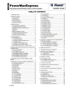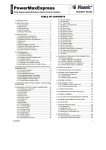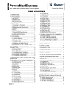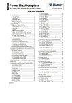
1
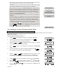
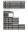
4.9.7 Enabling Keyfob Low Battery
Acknowledgement................................................... 52
4.10 DEFINE CUSTOM LOCATIONS ......................... 53
4.11 CONFIGURING OUTPUT PARAMETERS ......... 54
4.11.1 Preliminary Guidance................................... 54
4.11.2 Define PGM.................................................. 54
4.12 Programming User Settings ................................ 58
Configuring Remote Programming Access Permissions
..................................................................................... 59
5 DIAGNOSTIC TEST...................................................... 61
5.1 Testing Devices ..................................................... 62
5.1.1 Testing all Devices......................................... 62
5.1.2 Testing One Device ....................................... 62
5.1.3 Displaying Signal Strength Indication of All
Devices ................................................................... 63
5.1.4 Displaying Signal Strength Indication of RF
Devices ................................................................... 63
5.1.5 GPRS Communication Test........................... 64
5.1.6 LAN Connection Test..................................... 65
5.1.7 LAN Reset Option .......................................... 66
6 CALLING UPLOAD/DOWNLOAD SERVER................. 67
7. MAINTENANCE ........................................................... 68
7.1 Handling System Troubles .................................... 68
7.2 Dismounting the Control Panel.............................. 69
7.3 Replacing the Backup Battery ............................... 69
7.4 Fuse Replacement ................................................ 69
7.5 Replacing/Relocating Detectors............................ 69
7.6 Restore Factory Defaults....................................... 69
7.7 Viewing Serial Number .......................................... 70
8 READING THE EVENT LOG........................................ 70
8.1 Reading the Event Log.......................................... 70
8.2 Erasing and Exiting the Event Log ........................ 71
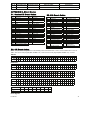
APPENDIX A. Detector Deployment & Transmitter
Assignments..................................................................... 71
A1. Detector Deployment Plan .................................... 71
A2. Keyfob Transmitter List ......................................... 72
A3. Emergency Transmitter List .................................. 72
A4. Non-Alarm Transmitter List ................................... 72
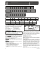
APPENDIX B. Event Codes............................................. 73
B1. Contact ID Event Codes ....................................... 73
B2. SIA Event Codes................................................... 73
B3. 4/2 Event Codes.................................................... 73
B4. Understanding the Scancom Reporting Protocol
Data Format................................................................. 74
APPENDIX C. Glossary ................................................... 74
APPENDIX D. DEFAULT AND PROGRAMMED ZONE
DEFINITIONS .................................................................. 76
MESSAGE TO THE INSTALLER
The PowerMax10-G2 control panel is supplied with 3 instruction manuals:
Installer Guide (this manual - for your exclusive use)
User’s Guide (for your use during installation only - Must be handed over to the master user after testing the system)
Accessories Guide (includes a full description of devices that are supported by the PowerMax10-G2 system)
Appendices A.1 and A.2 will help you prepare an installation plan. Please take time to fill out the forms - your job will
become much easier and confusion will be prevented. Filling out the forms will also help you create a list of detectors and
transmitters that must be obtained for the particular application. Compatible detectors and transmitters are listed in the
Accessories Guide.
Remember - it is advisable to power up the control panel temporarily after unpacking and program it on the work bench, in
accordance with the installation plan.
Although setting the correct time and date is one of the user tasks, we recommend that you set the time and date in the
course of programming. Access to the “User Settings” for the installer is possible through the installer‘s menu or through
the user menu (see User’s Guide section 2).
After programming, proceed to install the system as detailed in the Installation Instructions, from paragraph 3.3 Mounting
the Unit onward.
The installer should verify line seizure. Be aware of other phone line services such as DSL. If DSL service is present on the
phone line, you must install a filter. It is suggested to use the DSL alarm filter model Z-A431PJ31X manufactured by
Excelsus Technologies, or equivalent. This filter simply plugs into the RJ-31X jack and allows alarm reporting without
breaking the internet connection.
2
D-302756