1
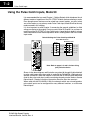
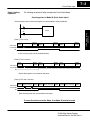
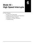
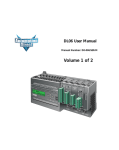
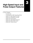
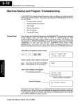
Mode 50 –
Pulse Catch Inputs
In This Chapter. . . .
Ċ Wiring the Pulse Catch Inputs
Ċ Configuring the Pulse Catch Parameters
Ċ Verification of Proper Operation
Ċ Troubleshooting
17
7–2
Pulse Catch Input
Mode 50
Pulse Catch Input
Using the Pulse Catch Inputs, Mode 50
It is recommended that you read Chapter 1, Getting Started, which introduces the six
different modes of operation of the D2–CTRINT module, before selecting a mode.
Even though several features can be mixed from several modes, you must select
one of the modes as your primary mode. Pulse Catch Input, Mode 50 will be the only
mode covered in this chapter.
It is also important to read Chapter 2, concerning the general guidelines for field
wiring your device to the module. You may want to refer to Chapter 2 as you learn to
make use of the D2-CTRINT’s Pulse Catch Inputs. A good place to begin is to learn
what each channel of the module represents when it is being used in the Pulse Catch
Input mode.
Default Settings for Pulse Catch Input Mode 50
D2–CTRINT Terminals
CW
CCW
DL240/250–1/260
DL230
00
00
Pulse Catch
01
D2
Dis. Input
02
03
Dis. Input
Dis. Input
04
Pulse Catch
01
02
03
Pulse Catch
Pulse Catch
Pulse Catch
04
Not Used
UP Counters
Not Used
Installation and
Safety Guidelines
Note: Refer to pages 2–4 and 2–5 when wiring
your particular device.
Shown in the above diagram and illustration are points 00 through 03 which default
to pulse catch inputs when the module is used with the DL240/250–1/260 and set to
operate in Mode 50. When the module is used with the DL230 only point 00 can be
used for the pulse catch input, and the remaining channels can be used as discrete
filtered inputs. Chapter 8 contains information about the filter time constant.
When used with the DL240/250–1/260, the channels which are not configured as
pulse catch inputs can be configured for many different functions, or as discrete
filtered inputs.
DL205 High Speed Counter
Interface Manual, 2nd Ed, Rev. A
7–3
Pulse Catch Input
Pulse Catching
Explained
The following example will help to explain the Pulse Catch Mode.
Counting pulses in Mode 50 (Pulse Catch Input)
Counting input pulses in the user program has some problems to be considered.
X0
C0
CNT
CT1
K9999
Pulse input
to Point 00
Output
Input
Update Solve user logic Update
Output
Input
Update Solve user logic Update
Output
Input
Update Solve user logic Update
Mode 50
Pulse Catch Input
[Case 1] This is okay.
X0
In this case, the pulse can be counted correctly.
[Case 2] This is not okay.
Pulse input
to Point 00
Output
Input
Update Solve user logic Update
Output
Input
Update Solve user logic Update
Output
Input
Update Solve user logic Update
X0
[Case 3] This also is not okay.
Pulse input
to Point 00
Output
Input
Update Solve user logic Update
Output
Input
Update Solve user logic Update
Output
Input
Update Solve user logic Update
X0
Both of these pulses are also counted as one pulse.
To count the pulses correctly, Mode 10 or Mode 20 should be used.
DL205 High Speed Counter
Interface Manual, 2nd Ed, Rev. A
Installation and
Safety Guidelines
Both of these pulses are counted as one pulse.
7–4
Pulse Catch Input
Mode 50
Pulse Catch Input
Understanding V-Memory
Setup Locations
The Pulse Catch Input, Mode 50, associated with the D2-CTRINT requires
V-memory configuration in order to be used.
V-memory location V7633 is the most important of all the reserved memory areas
because it stores the value which lets the CPU know which mode has been selected.
The following diagram shows the 16–bit word and the various information it stores,
including the values used for the Counter Interface Module.
The example shown here uses the Pulse Catch Input, Mode 50, the lower and upper
bits are set to 10 so the backup battery is enabled. Together they form the
hexadecimal number 1050.
Bits
15
14
13
Memory Location V7633
12 11 10 9
8
7
6
5
0
0
0
1
0
Installation and
Safety Guidelines
UP Counters
1
0
0
0
0
1
0
0
5
4
3
2
1
1
0
0
0
0
0
0
Miscellaneous Setup
Binary Coded Decimal:
D2-CTRINT Mode Setup
Binary Coded Decimal:
00 = Not Used (default)
10 = Battery Enabled (DL230/240/250–1/260)
20 = Power Up in Run (DL230 only)
30 = Selects both Battery Enable
and Power Up in Run (DL230 only)
40 = Mode Change Enable in K–sequence (DL240 only)
50 = Battery Enable and Mode Change Enable
in K–sequence (DL240 only)
00 = Not Used
10 = UP Counting Mode
20 = UP/DOWN Counting Mode
30 = Pulse Output Train
40 = High Speed Interrupts
50 = Pulse Catch Inputs
60 = Discrete Filtered Inputs
NOTE: It is important to look at the entire 16 bits at V7633. If the RLL program only
sets the bits in the lower byte when entering the Counter Interface mode value, the
upper bits will be overwritten with zeros (0’s). Always enter a 4-digit BCD value in the
V-memory. This way, the proper value will be written into the upper bits.
There are also other V-memory locations which contain Counter Interface setup
information for each I/O point. They will be automatically configured with default
values for each Counter Interface mode selected.
DL205 High Speed Counter
Interface Manual, 2nd Ed, Rev. A
7–5
Pulse Catch Input
Default Settings
When xx50 is written to V7633, the CPU places the following default codes in
V-memory.
Configuration
Point 00/V7634 Point 01/V7635 Point 02/V7636 Point 03/V7637 Point 04
DL230
Hexadecimal
Code
Pulse Catch Input Not Used
0005
0000
DL240/250–1/260
Hexadecimal
Code
Pulse Catch Input Pulse Catch Input Pulse Catch Input Pulse Catch Input Not Used
0005
0005
0005
0005
Not Used
0000
Not Used
0000
Not Used
CW
D2–CTRINT Terminals
CCW
DL230
D2
DL240/250–1/260
00
00
Pulse Catch
01
Not Used
02
03
04
Not Used
Not Used
Not Used
Pulse Catch
01
02
03
04
Mode 50
Pulse Catch Input
Default Settings for Interrupt Input Mode 60
Pulse Catch
Pulse Catch
Pulse Catch
Pulse Catch
Note: Refer to pages 2–4 and 2–5 when wiring
your particular device.
Installation and
Safety Guidelines
DL205 High Speed Counter
Interface Manual, 2nd Ed, Rev. A
7–6
Pulse Catch Input
Custom Configuration
Up to this point, only Mode 50 default settings have been discussed. The default
settings will be suitable for many applications and will not require a custom
configuration. However, for those applications needing the defaults changed so the
D2–CTRINT will work for the applications, use the following table which contains the
options available.
UP Counters
Mode 50
Pulse Catch Input
Mode 50 Options
Point Number
V-Memory
Location
Possibility (One per point)
Hex Value
point 00
p
V7634
Pulse Catch Input
0005 (DL240/250–1/260) default
High Speed Interrupt (timed)
ttt4 (ttt=1 to 999ms timer setting)
Discrete Filtered Input
xx06 (xx=filter time)
High Speed Interrupt
(DL240/250–1/260)
0004
Pulse Catch Input
(DL240/250–1/260)
0005 (DL240/250–1/260) default
Discrete Filtered Input
xx06 (xx=filter time)
High Speed Interrupt
(DL240/250–1/260)
0004
Pulse Catch Input
(DL240/250–1/260)
0005 (DL240/250–1/260) default
Discrete Filtered Input
xx06 (xx=filter time)
High Speed Interrupt
(DL240/250–1/260)
0004
Pulse Catch Input
(DL240/250–1/260)
0005 (DL240/250–1/260) default
High Speed Interrupt
(DL240/250–1/260)
0004
Discrete Filtered Input
xx06 (xx=filter time)
Not available in Mode 50
––––
point 01
point 02
Installation and
Safety Guidelines
point 03
point 04
V7635
V7636
V7637
V7637
DL205 High Speed Counter
Interface Manual, 2nd Ed, Rev. A
7–7
Pulse Catch Input
Setting UP the CPU for the Pulse Catch Inputs
Configuring the
V–Memory
Mode 50
Pulse Catch Input
Step 1:
Enter the
Mode Selected
The DL240, DL250–1 or DL260 CPUs checks the V-memory to see if there is a
D2–CTRINT Module present. There will be the value 10, 20, 30, 40, 50 or 60 in
V7633 if the module has been properly configured. If the CPU finds that a Counter
Interface module is present, other V-memory locations will be checked to see how
the module has been configured.
The values can be entered into memory by using either a handheld programmer or
by editing them into a control program using DirectSOFT32. The following
examples will show how to use DirectSOFT32 to configure the Pulse Catch Inputs.
If Mode 50, Pulse Catch Input, has been chosen as the primary function, the value 50
must be placed in V7633. The following DirectSOFT32 diagram shows the setup
procedures for communicating with the DL240/250–1/260 CPU. Refer to the
DirectSOFT32 Programmers User Manual for more details.
Setting the
V-Memory
using RLL
Installation and
Safety Guidelines
Setting the
V-Memory
using the
Memory
Editor
Editing the D2–CTRINT setup at the beginning of the user program is the most
efficient method for setting up the counter mode. Should there be a need to change
any of the counter setup values after the PLC has been put in the RUN Mode, use the
Memory Editor to change the values. These values will only be temporary. They
should be put into the program if they are to be used permanently.
DL205 High Speed Counter
Interface Manual, 2nd Ed, Rev. A
7–8
Pulse Catch Input
The following RLL example shows how to set the Pulse Catch Input, Mode 50, in
V–memory location V7633.
DirectSOFT32 Display
SP0
LD
K50
Load Mode 50 in Accumulator
OUT
V7633
UP Counters
Mode 50
Pulse Catch Input
Transfer Contents of
Accumulator to V7633
Two commands are needed to put the values into V-memory. The value must first be
loaded into the accumulator of the CPU, then the CPU must transfer the value to the
memory location. In this case, 50 is to be placed in V7633. This value is loaded into
the accumulator, LD K50. The CPU then writes this data to the memory location
V7633, once it reads the OUT command, OUT V7633. Notice that an SP0 contact is
used in this rung. This relay is on for the first scan only. This will load the values into
memory initially, thereby keeping the scan time to a minimum.
Step 2:
How Many Pulse
Catch Inputs
Up to four(4) pulse catch inputs can be used with the DL240/250–1/260 CPUs and
one (1) pulse catch input for the DL230 CPU. The following steps will discuss the
programming for each channel which has an interrupt device wired to it.
Step 3:
Configure the
V-Memory
The table below gives a description for each of the V-memory locations that must be
configured for each I/O point which are selected to have high speed interrupt
capability.
Installation and
Safety Guidelines
V–Memory
Description
V7633
Primary Mode (Pulse Catch=50)
V7634
Point 00
V7635
Point 01
V7636
Point 02
V7637
Point 03
DL205 High Speed Counter
Interface Manual, 2nd Ed, Rev. A
7–9
Pulse Catch Input
In the below example, Channels 1 and 2 are configured as Pulse Catch Inputs,
Channel 3 is to be a Discrete Filtered Input, and Channel 4 to be an Interrupt Input.
DirectSOFT32 Display
SP0
LD
K5
OUT
V7634
Pulse Catch Input at Point 00
LD
K5
OUT
V7635
Pulse Catch Input at Point 01
LD
External Interrupt at Point 02
LD
K1006
OUT
V7637
Discrete Input w/10 ms filter;
at Point 03
Mode 50
Pulse Catch Input
K4
OUT
V7636
Notice that the hex number 5 is stored in the V-memory locations for each I/O point
which are to be Pulse Catch Inputs. The number 4 is used for an external interrupt at
an I/O point, and Kxx06 is used for a programmable discrete filtered input (where xx
represents the filtering time constant in milliseconds.)
Installation and
Safety Guidelines
DL205 High Speed Counter
Interface Manual, 2nd Ed, Rev. A
7–10
Pulse Catch Input
Installation and
Safety Guidelines
UP Counters
Mode 50
Pulse Catch Input
Troubleshooting
The following information may provide some assistance in handling any problems
which may be encountered when setting up the D2–CTRINT module, should they
occur. Experience has shown that most problems occur because of improper
configuration. Always re-check configuration before anything else.
For verifying types of inputs (or outputs) which do not relate to the Pulse Catch Input,
see the Chapters in this manual covering the specific function. Listed below are
some things that could possibly go wrong with the high speed interrupt inputs:
1. No pulse catching appears to be taking place.
2. The status indicator LED is not lit for the input point where the pulse
catching is wired (i.e. points 00 and 01).
Defective Field Device - If a field device is suspected to be faulty, verify its proper
operation first. Examine the characteristics of the pulses being received with an
oscilloscope, test equipment type digital counter, or an inexpensive logic probe.
Touch probe to
counter input points.
Field device must be
wired so that pulses
are being sent.
Typical Low Cost Logic Probe
(Not available from AutomationDirect)
High Signal Indicator
Low Signal Indicator
Pulse Train Indicator
Normal/Pulse Train Switch
TTL/CMOS Switch
Connect power leads to your recommended
power supply––not PLC power supply.
Check the specifications for the field device. Make certain that the output signal
matches the specifications of the D2–CTRINT module.
Pulse Width – The pulse width may be too narrow. The positive transition must
remain HIGH for at least 0.1 ms in order for the module to detect its presence.
Wiring - Simple as this might seem, quite often poor wiring is the cause of many
problems. Be sure there is a complete electrical loop between the device and the
input module. Along with visual inspection, use a voltmeter to check the wiring.
Input Voltage - If the input device is sending a signal that is less than 12 volts, most
likely the counter will not function or function improperly. Replace the field device
with one which has the proper output level if necessary.
Improper Configuration - Verify that proper values have been used in the
configuration. If interfacing a DL230, point 00 is the only point available for pulse
catching.
Status Indicators – Make sure the PWR or BAT LED’s are not lit on the CPU. Be
sure that the status indicators are lit as the pulse signals are received at the proper
input point on the D2–CTRINT module. If an LED is not functioning, check the point
with a voltmeter to be sure that the I/O point is being energized. .
DL205 High Speed Counter
Interface Manual, 2nd Ed, Rev. A