1
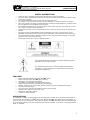
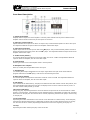
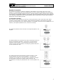
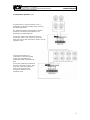
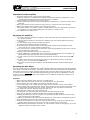
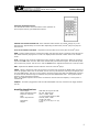
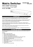
40 Watt Mixer Amplifier
with Media Player
Owners Manual
Model #USB-80
©2009 MCM Electronics
MCM Custom Audio
MCM Electronics
Centerville, Ohio
www.mcmelectronics.com
USB-80 Mixer Amplifier
Owners Manual
SAFETY INSTRUCTIONS
•
•
•
•
•
•
•
•
•
Please be sure to read all the instructions carefully before using this product.
As several safety messages are printed in this instruction sheet, please be sure to observe these
as they are important.
It is recommended that this manual be kept for future reference.
Do not store or use this device in dusty or humid locations, or in direct exposure to sunlight.
Take care to protect the power cord from damage, pinching or being stepped on, primarily where
the cord attaches to the amplifier and at the plug.
Do not defeat the polarized or grounding feature of the power cord plug. If the plug will not fit in
your outlet, consult a licensed electrician.
Disconnect the power cord during electrical storms, or when the product will be unused for long
periods.
Servicing is highly recommended if product is damaged in any way, when the power cord is
damaged, when liquid has been spilled or objects have fallen into the device. Servicing will also
be required when this device has been exposed to rain, does not operate normally, or has been
subject to high level of physical shock.
Servicing should be done only by qualified personnel.
The lightning flash with arrow within a triangle indicates that parts
inside are a risk of electrical shock.
The exclamation point within a triangle indicates that important
operation or service instructions are located within the products
accompanying paperwork.
FEATURES
•
•
•
•
•
•
•
•
•
•
•
Built in USB and SD/MMC card reader with MP3 player
Infrared remote control of all MP3 player options
LCD Display of audio track being played
Sequential, programmable and random track playing
Single Channel (monaural) 40 Watt RMS output amplifier
Speaker outputs for 4Ω, 8Ω and 16Ω speaker systems, plus 70V for distributed systems
Fixed line level REC output
Four input mixer with three microphone and one line level input
Separate level control for each mixer input
Master bass and treble controls
110VAC or 12VDC operation
APPLICATIONS
This amplifier is suitable for background music and paging use in small retail, commercial and industrial
environments. The inclusion of an MP3 player with USB and SD/MMC card reader allows easy addition of
hours of music to any environment. The reader will directly read MP3 and WMA files from standard thumb
drives and flash memory. Files may be played in the order they appear on the drive, in a preprogrammed
order, or randomly.
2
USB-80 Mixer Amplifier
Owners Manual
Front Panel Description
1. Output Power Meter
Displays relative output level of the amplifier. Left most yellow indicator acts as power indicator for the
amplifier and will remain continuously lit when power is turned on.
2. Input #1~3 Level Controls
Adjusts individual level input for the three mic inputs. Fully counterclockwise position is off for each input.
This adjustment affects all inputs as fed to the amplifier and the REC output.
3. Input #4 Level Control
Adjusts input level for the AUX input as well as the MP3 player. Fully counterclockwise position includes a
detent off position which turns power off to the MP3 player. This adjustment affects all inputs as fed to the
amplifier and the REC output.
4. Treble control (master)
This control adjusts high frequencies centered at 10KHz at a rate of ±10dB. This adjustment affects all
inputs as fed to the amplifier, but not to the REC output.
5. Power Switch
Rocker type switch turns on the amplifier when in the UP position.
6. Microphone #1~3 Inputs
Each 1/4" female jack accepts balanced mic level input.
7. AUX #4 Input
1/4" female jack accepts unbalanced line level input. Signal fed to this input will be mixed with the
program material from the MP3 player, with the level of both being the same.
8. Bass control (master)
This control adjusts low frequencies centered at 100Hz at a rate of ±10dB. This adjustment affects all
inputs as fed to the amplifier, but not to the REC output.
9. LCD Display
Upon insertion of the flash memory, the player will determine the total number of music files present, and
then automatically begin playing the first file. The display shows a numeric value for each file, from 1 to
the total number of files present, up to 999.
10. Previous File Select
During song play, depressing this button will revert back to the previous file on the thumb drive or flash
memory. From that point, each time the Previous File Select button is depressed, the player will increment
back one file on the play list. Once the first file is reached, depressing the button will jump to the last song
on the play list.
11. Next File Select
Depressing this button will advance to the next file on the thumb drive or flash memory. From that point,
each time the Next File Select button is depressed, the player will increment forward one file on the play
list. Once the last file is reached, depressing the button will return to the beginning of the play list.
12. Stop
Depressing this button will stop the play of the current file.
3
USB-80 Mixer Amplifier
Owners Manual
13. Play/Pause
Depressing this button will start playing the current file displayed on the screen from the beginning.
Depressing this button while a song is playing will pause that song at its current point. Depressing again
will resume play from the paused point. Repeatedly depressing the Play/Pause button will toggle the
player between Pause and Play action.
14. SD/MMC Card Slot
This slot accepts standard SD or MMC flash memory, readily available from MCM Electronics or any
computer retailer. The player will read MP3 and WMA files directly from the flash memory, regardless of
whether the file is in the root directory or sub folders. Other files (music or otherwise) that reside on the
flash memory will be ignored.
15. IR Sensor
Receives remote control commands from the included IR remote control.
16. USB Flash Memory Interface
This slot accepts standard USB thumb drives, readily available from MCM Electronics or any computer
retailer. The player will read MP3 and WMA files directly from the thumb drive, regardless if the file is in
the root directory or sub folders. Other files (music or otherwise) on the drive will be ignored.
17. Repeat
Selects the repeat function for the MP3 player. Depressing this button will toggle the player between three
Repeat modes; OFF, Repeat Current File, Repeat All Files.
Rear Panel Description
18. DC Fuse Holder
Holder contains fuse that provides protection when amplifier is powered by 12VDC. This fuse should be
replaced only with a 7A / 250V fast blow type fuse.
19. Speaker Output Terminal Strip
Provides screw terminal speaker connection. Note that taps exist for 4, 8 and 16 ohm speakers, as well as
for distributed 70V systems. It is critical that only one tap be used when connecting speakers.
Note: Improper speaker connection can lead to permanent damage to the amplifier.
20. Record Output
1/4" female jack provides line level output, intended to drive the input of a tape or similar recorder. It
may also be used to drive a separate amplifiers line level input for additional zones.
21. DC Power Input Terminal Strip
Provides screw terminal power connection when unit is powered by 12VDC. Note connections are labeled
(+) and (–). It is critical that correct polarity is observed.
Note: Incorrect polarity will result in permanent damage to the amplifier.
22. AC Fuse Holder
Holder contains fuse that provides protection when amplifier is powered by 120VAC. This fuse should be
replaced only with a 2A / 250V fast blow type fuse.
23. AC Power Cord Inlet
AC power cord is permanently attached to this amplifier and may not be removed.
4
USB-80 Mixer Amplifier
Owners Manual
Speaker Connection
It is possible to connect any number of speakers to this amplifier, from a single unit to 20 or more.
However, it is critical that proper wiring configurations are used, otherwise potentially poor performance,
and likely permanent amplifier damage will result. Generally speaking, speaker systems can be classified
in two groups. Low impedance speakers, such as 8ohm, which are typical of those used in home audio and
other high fidelity applications, and 70V high impedance type, normally found in larger scale commercial
background music and paging systems.
Low Impedance Speakers
Most commonly, these speakers are 8 ohm (Ω), but may also be 4Ω, 16Ω or some other value. When
connecting a single speaker to the amplifier, simply match the impedance of the speaker to the label
shown on the terminal strip. If the exact impedance is not available, connect to the next LOWEST tap. For
instance, if the speaker impedance is 6Ω, connect to the 4Ω tap.
The adjacent illustration shows connection of a single 8Ω speaker to the
amplifier.
If multiple speakers are connected, they may be connected in series, as
shown in the adjacent illustration. In this case, you simply add the
impedance of each speaker. Two 8Ω speakers connected in series
create a 16 load. This arrangement is normally only practical when four
or fewer speakers are used.
The adjacent illustration demonstrates a parallel connection. In this
case all speakers must be the same impedance. You divide the
impedance of one speaker by the total number of speakers connected.
Two 8Ω speakers connected in parallel creates a 4Ω load. This
arrangement is normally only practical when four or fewer speakers are
used.
5
USB-80 Mixer Amplifier
Owners Manual
Low Impedance Speakers (cont)
In certain cases, it may be necessary to use a
combination of series and parallel wiring to achieve
the desired impedance.
The adjacent illustration demonstrates a common
method of connecting four 8Ω speakers, and
maintaining a combined 8Ω load.
In this case, speakers are separated into pairs,
connected in series. Each series pair yields 16Ω.
Since both sets are then connected in parallel, the net
impedance is 8Ω.
In this second example of a
combination of series and parallel
wiring, eight 8Ω speakers are
combined to create a combined 4Ω
load.
In this case, speakers are separated
into pairs, connected in series. Each
of the four series pair yields 16Ω.
Since the four pairs are then
connected in parallel, the net
impedance is 4Ω.
6
Owners Manual
USB-80 Mixer Amplifier
70V Distributed Speakers
These high impedance speakers are typically used in application requiring a large number of speakers, or
when extremely long speaker wire runs are necessary. In this application, all speakers are connected in
parallel, and may be wired in a "daisy chain" configuration. It is not necessary to "home run" wire from
each speaker back to the amplifier. Shown below is a very typical arrangement of (14) 70V speakers
connected to the USB-80 amplifier.
Typically, speakers having attached 70V transformers will have multiple wattage taps available for
connection. For example, the very popular MCM Custom Audio ceiling speaker, Model #555-9018, includes
taps for 0.325W, 0.625W, 1.25W, 2.5W, 5W and 10W. The popular outdoor speaker Model #80-492
includes a rotary selector for selection of 5W, 10W, 20W and 30W.
In the above case, any number of speakers can be connected to a 70V amplifier output, as long as the
total wattage of all speaker taps does not exceed the total RMS wattage rating of the amplifier. For
example, if tapped at 1.25 watts, a total of (32) Model #555-9018 ceiling speakers could be connected to
the 555-9750 amplifier. If tapped at 5W, a total of (8) Model #80-492 outdoor speakers could be
connected.
A second benefit of this type of arrangement is the ability to vary sound level in different areas. If higher
volume is desired in some areas than others, simply select a higher tap in those areas. This is completely
suitable as long as the total of all speaker taps does not exceed the rated output of the amplifier.
As mentioned above, these speakers are much higher impedance than conventional consumer high fidelity
speaker systems. For example, a 70V speaker, tapped at 1W will have a nominal impedance of 5,000Ω. If
tapped at 5W, the same speaker would have an impedance of 1,000Ω. Because of this, loss from long
speaker wire runs is greatly reduced.
70V Distributed Speakers (cont)
The following chart shows typical maximum lengths allowable in 70V systems
Output power per wire run
Wire
Gauge
5W
10W
15W
30W
50W
100W
200W
16
10,000
7,000
4,600
2,300
1,400
700
350
18
9,000
4,500
2,800
1,400
830
415
205
20
5,500
2,700
1,800
900
540
270
135
22
3,400
1,700
1,100
550
330
115
60
24
2,100
1,000
700
350
210
105
50
Maximum distance of cable run (ft.)
For example, it is desired to locate a 10W paging horn some distance from an office in a large warehouse.
Considering wiring requirements, the length of the speaker cable will need to be approximately 4,000 ft.
As shown above, 18 gauge wire will be suitable for this installation.
7
USB-80 Mixer Amplifier
Owners Manual
Installation of the Amplifier
• Be certain that the power is removed from the amplifier
• Locate the amplifier in a suitable shelf or tabletop. If positioned with other components, it is not
recommended that other devices be located on top of the amplifier.
• Connect speakers as described in the previous pages
• Connect desired input sources such as microphones to the MIC inputs, or a line level device to the
AUX input
• Make certain that the volume controls for each of the #1~4 inputs are set to the minimum
• Make certain that the power switch is in the OFF (down) position
• Connect the amplifier to a suitable 12VDC or 120VAC power source. Note that at full output power,
this amplifier will require approximately 6A if connected to a 12VDC source.
• The amplifier is now ready for use
Operating the amplifier
• If this is the first time operating the amplifier, make certain that all volume adjustments are set to
the minimum position
• Be certain that the amplifier is connected to a suitable power source and speakers are properly
connected
• Turn the amplifier power switch to the ON (up) position
• The leftmost yellow OUTPUT indicator should light
• If microphones are connected, speak into the microphone and adjust the appropriate volume
control until the mic volume reaches the desired level
• If a line level device is connected to the AUX input. adjust the appropriate volume control until the
volume reaches the desired level
• Adjust the Bass and Treble controls to the desired level
• If an SD or MMC card, or USB thumb drive is inserted into the appropriate slot, the amplifier will
automatically begin playing the first music file (see details below)
• The AUX volume level control will simultaneously adjust the level of the AUX input and the MP3
player
• The AUX volume control has an OFF detent in the full counterclockwise position. In this OFF
position, power is removed from the MP3 player
• While audio is played through he amplifier, the LED OUTPUT indicator will show relative power
output
Operating the MP3 Player
The built in media player is compatible with all MP3 and WMA audio files, and will play them automatically
when media is inserted into the player. It should be noted however that certain MP3 files downloaded from
subscription services may contain copyright protection that will prevent them from being played in this
unit. Also, this unit will not read iTunes files downloaded for the iPod. As with any MP3player, the most
reliable source for music files to play on this amplifier is MP3 or WMA files created from ripping CD's or
copying vinyl on a standard PC.
P
Operation
• Make certain the amplifier power switch is in the ON position
• Make certain the AUX volume level is fully counterclockwise in the OFF position
• Insert a thumb drive, SD or MMC card containing desired music files
• Turn the MP3 player on by rotating the AUX volume control clockwise to the 9 o'clock position
• The LCD display will remain blank while the MP3 player determines the number of music files on the
inserted media. Depending upon the number of music files, this may take several seconds.
• The display will show 001 and begin playing the first song
• Adjust the AUX volume control to the desired level
• The MP3 player will sequentially play each song and stop after finishing the last
• Songs may be manually repeated or skipped using the PREV and NEXT buttons
• Pressing the STOP button once will stop the song, pressing play again will start the current song
again from the point it was stopped
• Pressing the STOP button twice will cause the MP3 player to revert back to the beginning of the list
• PLAY and PAUSE functions are both located on the same button
• Pressing play will begin the current song. Pressing while the song is playing will pause the song.
Pressing again will cause the song to resume from the point where it was paused
• REPEAT button toggles between two modes. R1 will continually repeat the song playing, R-ALL will
repeat all songs on the media device in order
P
P
8
Owners Manual
USB-80 Mixer Amplifier
Using the IR Remote Control
The included IR remote control will allows remote operation of
all front panel controls, plus additional functions.
Shaded area buttons labeled 0~9 –Allow individual track selection by number. Simply key in the
desired track. Approximately one second after depressing the last button, the MP3 player will play the
desired track
P
Four arrow buttons on bottom – Replicates controls located on the front panel of the MP3 player
RAN – Selects random function. Pressing this button will cause the player to randomly select the files on
the media instead of playing them in order. The display flashes the track number while in the random
mode.
A>B – Allows the user to select a desired clip of any length to repeat continuously. While clip is playing,
depress the A>B button one time. Wait a few seconds and press the button again. The selected clip will
then continuously repeat. This will occur until the A>B button is depressed a third time to exit this mode.
REP – Replicates the REPEAT control located on the front of the MP3 player.
P
PROG – Allows a specific list of files to be played in a preset order. Depress the PROG button one time to
enter the program mode. Once in this mode, use the 0~9 keys to select the first song to be played, then
pres the PROG button. Use the 0~9 keys again to select the second song and pres PROG again. Continue
to do this until all desired songs are selected, then press the PROG button twice. Then press the PLAY
button to begin playing the sequence.
Note: The program sequence will be lost if the media is removed from the amplifier, or if the power is
switched off.
USB/SD – If media is plugged into both the USB and SD/MMC card slot, this button will toggle between
the two.
Amplifier Specifications
Power output:
Output transformer taps:
Frequency response:
THD:
Power requirements:
Dimensions:
Weight:
40W RMS, driving an 8Ω load
4Ω, 8Ω, 16Ω and 70V
50Hz ~ 20KHz ±3dB
<1.0% at rated output at 1KHz
120VAC, 60Hz, 120W
12VDC, 6A (max)
4 1/8" (H) x 15" (W) x 10" (D)
14 lbs.
9