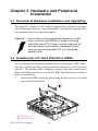
1
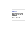
PPC-V106
Fanless Vehicle Mounted
Terminal with 10.4" TFT LCD
User’s Manual
Copyright
This document is copyrighted, © 2004. All rights are reserved. The original manufacturer reserves the right to make improvements to the products
described in this manual at any time without notice.
No part of this manual may be reproduced, copied, translated or transmitted in any form or by any means without the prior written permission of
the original manufacturer. Information provided in this manual is
intended to be accurate and reliable. However, the original manufacturer
assumes no responsibility for its use, nor for any infringements upon the
rights of third parties that may result from such use.
Acknowledgements
Award is a trademark of Award Software International, Inc.
VIA is a trademark of VIA Technologies, Inc.
IBM, PC/AT, PS/2 and VGA are trademarks of International Business
Machines Corporation.
Intel and Pentium are trademarks of Intel Corporation.
Microsoft Windows® is a registered trademark of Microsoft Corp.
RTL is a trademark of Realtek Semi-Conductor Co., Ltd.
ESS is a trademark of ESS Technology, Inc.
UMC is a trademark of United Microelectronics Corporation.
SMI is a trademark of Silicon Motion, Inc.
Creative is a trademark of Creative Technology LTD.
All other product names or trademarks are properties of their respective
owners.
For more information on this and other Advantech products, please visit
our websites at:
http://www.advantech.com
http://www.advantech.com.tw
For technical support and service, please visit our support website at:
http://service.advantech.com.tw/eservice
This manual is for the PPC-V106.
Part No. 2006V10630
2nd. Edition
Printed in Taiwan
April 2005
PPC-V106 User Manual
ii
FCC Class B
This equipment has been tested and found to comply with the limits for a
Class B digital device, pursuant to Part 15 of the FCC Rules. These limits
are designed to provide reasonable protection against harmful interference when the equipment is operated in a residential environment. This
equipment generates, uses and can radiate radio frequency energy. If not
installed and used in accordance with this user's manual, it may cause
harmful interference to radio communications. Note that even when this
equipment is installed and used in accordance with this user's manual,
there is still no guarantee that interference will not occur. If this equipment is believed to be causing harmful interference to radio or television
reception, this can be determined by turning the equipment on and off. If
interference is occurring, the user is encouraged to try to correct the interference by one or more of the following measures:
• Reorient or relocate the receiving antenna
• Increase the separation between the equipment and the receiver
• Connect the equipment to a power outlet on a circuit different from that
to which the receiver is connected
• Consult the dealer or an experienced radio/TV technician for help
Warning!
Any changes or modifications made to the
equipment which are not expressly approved by
the relevant standards authority could void your
authority to operate the equipment.
iii
Packing List
Before you begin installing your card, please make sure that the following
materials have been shipped:
• PPC-V106 series panel PC
• Accessories for PPC-V106
- Warranty card
- Power cord:
For AC Model: US type AC power cord.
For DC Model: DC power inlet cable (180cm)
-"Drivers, Utilities and User Manual" CD-ROM
- Packet of screws
If any of these items are missing or damaged, contact your distributor or
sales representative immediately.
PPC-V106 User Manual
iv
Additional Information and Assistance
Step 1. Visit the Advantech web site at www.advantech.com or
www.advantech.com.tw where you can find the latest information about the product.
Step 2. Contact your distributor, sales representative, or Advantech's customer service center for technical support if you need additional
assistance. Please have the following information ready before
you call:
• Product name and serial number
• Description of your peripheral attachments
• Description of your software (operating system, version, application
software, etc.)
• A complete description of the problem
• The exact wording of any error messages
Warning!
1. Input voltage rated:Input voltage rated :
AC model: 100-240 Vac, 50/60Hz, 2-1.5A.
DC model
a. 19-36 Vdc
b. 11.2-18 Vdc
c. 40-58 Vdc
2. Use a 3 V @ 195 mA lithium battery
3. Packing: please carry the unit with both hands, handle with care
4. Maintenance: to properly maintain and clean the surfaces, use only approved products or clean with a dry
applicator
5. CompactFlash: Turn off power before inserting or
removing CompactFlash storage card.
Contact information:
Our European representative:
Advantech Europe GmbH
Kolberger Straße 7
D-40599 Düsseldorf, Germany
Tel: 49-211-97477350
Fax: 49-211-97477300
v
Safety Instructions
1. Read these safety instructions carefully.
2. Keep this User's Manual for later reference.
3. Disconnect this equipment from any AC outlet before cleaning. Use a damp
cloth. Do not use liquid or spray detergents for cleaning.
4. For plug-in equipment, the power outlet socket must be located near the
equipment and must be easily accessible.
5. Keep this equipment away from humidity.
6. Put this equipment on a reliable surface during installation. Dropping it or letting it fall may cause damage.
7. The openings on the enclosure are for air convection. Protect the equipment
from overheating. DO NOT COVER THE OPENINGS.
8. Make sure the voltage of the power source is correct before connecting the
equipment to the power outlet.
9. Position the power cord so that people cannot step on it. Do not place anything
over the power cord.
10. All cautions and warnings on the equipment should be noted.
11. If the equipment is not used for a long time, disconnect it from the power
source to avoid damage by transient overvoltage.
12. Never pour any liquid into an opening. This may cause fire or electrical shock.
13. Never open the equipment. For safety reasons, the equipment should be
opened only by qualified service personnel.
14. If one of the following situations arises, get the equipment checked by service
personnel:
a. The power cord or plug is damaged.
b. Liquid has penetrated into the equipment.
c. The equipment has been exposed to moisture.
d. The equipment does not work well, or you cannot get it to work according
to the user's manual.
e. The equipment has been dropped and damaged.
f. The equipment has obvious signs of breakage.
15. DO NOT LEAVE THIS EQUIPMENT IN AN ENVIRONMENT WHERE
THE STORAGE TEMPERATURE MAY GO BELOW -20° C (-4° F) OR
ABOVE 60° C (140° F). THIS COULD DAMAGE THE EQUIPMENT. THE
EQUIPMENT SHOULD BE IN A CONTROLLED ENVIRONMENT.
16. CAUTION: DANGER OF EXPLOSION IF BATTERY IS INCORRECTLY
REPLACED.REPLACE ONLY WITH THE SAME OR EQUIVALENT
TYPE RECOMMENDED BY THE MANUFACTURER, DISCARD USED
BATTERIES ACCORDING TO THE MANUFACTURER'S INSTRUCTIONS.
The sound pressure level at the operator's position according to IEC 704-1:1982 is
no more than 70 dB (A).
DISCLAIMER: This set of instructions is given according to IEC 704-1. Advantech disclaims all responsibility for the accuracy of any statements contained
herein.
PPC-V106 User Manual
vi
Wichtige Sicherheishinweise
1. Bitte lesen sie Sich diese Hinweise sorgfältig durch.
2. Heben Sie diese Anleitung für den späteren Gebrauch auf.
3. Vor jedem Reinigen ist das Gerät vom Stromnetz zu trennen. Verwenden Sie
Keine Flüssig-oder Aerosolreiniger. Am besten dient ein angefeuchtetes Tuch
zur Reinigung.
4. Die NetzanschluBsteckdose soll nahe dem Gerät angebracht und leicht
zugänglich sein.
5. Das Gerät ist vor Feuchtigkeit zu schützen.
6. Bei der Aufstellung des Gerätes ist auf sicheren Stand zu achten. Ein Kippen
oder Fallen könnte Verletzungen hervorrufen.
7. Die Belüftungsöffnungen dienen zur Luftzirkulation die das Gerät vor überhitzung schützt. Sorgen Sie dafür, daB diese Öffnungen nicht abgedeckt werden.
8. Beachten Sie beim. AnschluB an das Stromnetz die AnschluBwerte.
9. Verlegen Sie die NetzanschluBleitung so, daB niemand darüber fallen kann.
Es sollte auch nichts auf der Leitung abgestellt werden.
10. Alle Hinweise und Warnungen die sich am Geräten befinden sind zu
beachten.
11. Wird das Gerät über einen längeren Zeitraum nicht benutzt, sollten Sie es vom
Stromnetz trennen. Somit wird im Falle einer Überspannung eine Beschädigung vermieden.
12. Durch die Lüftungsöffnungen dürfen niemals Gegenstände oder Flüssigkeiten
in das Gerät gelangen. Dies könnte einen Brand bzw. elektrischen Schlag auslösen.
13. Öffnen Sie niemals das Gerät. Das Gerät darf aus Gründen der elektrischen
Sicherheit nur von authorisiertem Servicepersonal geöffnet werden.
14. Wenn folgende Situationen auftreten ist das Gerät vom Stromnetz zu trennen
und von einer qualifizierten Servicestelle zu überprüfen:
a - Netzkabel oder Netzstecker sind beschädigt.
b - Flüssigkeit ist in das Gerät eingedrungen.
c - Das Gerät war Feuchtigkeit ausgesetzt.
d - Wenn das Gerät nicht der Bedienungsanleitung entsprechend funktioniert
oder Sie mit Hilfe dieser Anleitung keine Verbesserung erzielen.
e - Das Gerät ist gefallen und/oder das Gehäuse ist beschädigt.
f - Wenn das Gerät deutliche Anzeichen eines Defektes aufweist.
15. VOSICHT: Explisionsgefahr bei unsachgemaben Austausch der Batterie.Ersatz nur durch densellben order einem vom Hersteller empfohlenemahnlichen Typ. Entsorgung gebrauchter Batterien navh Angaben des
Herstellers.
Der arbeitsplatzbezogene Schalldruckpegel nach DIN 45 635 Teil 1000
beträgt 70dB(A) oder weiger.
vii
DISCLAIMER: This set of instructions is given according to IEC704-1.
Advantech disclaims all responsibility for the accuracy of any statements
contained herein.
PPC-V106 User Manual
viii
Contents
Chapter
1 General Information ........................................2
1.1
1.2
1.3
1.4
Chapter
Introduction ....................................................................... 2
General Specifications....................................................... 2
LCD Specifications ........................................................... 5
Dimensions........................................................................ 6
2 System Setup.....................................................8
2.1
A Quick Tour of the Panel PC .......................................... 8
Figure 2.1:Front View of the Panel PC........................... 8
Figure 2.2:Right Side of Panel PC.................................. 8
Figure 2.3:Rear Side View of the Panel PC.................... 9
Figure 2.4:Panel PC I/O (DC model).............................. 9
2.2
Installation Procedures .................................................... 10
2.2.1
2.2.2
2.2.3
2.3
2.4
2.5
Chapter
Connecting the Power Cord.......................................... 10
Connecting the Keyboard or Mouse ............................. 10
Switching On the Power ............................................... 10
Running the BIOS Setup Program .................................. 11
Installing System Software.............................................. 12
Installing the Drivers....................................................... 13
3 Hardware and Peripheral Installation .........16
3.1
3.2
3.3
Overview of Hardware Installation and Upgrading ........ 16
Installing the 2.5" Hard Disk Drive (HDD) .................... 16
Placing the Rubber Seal .................................................. 17
3.4
Installing the Universal Arm ........................................... 18
Figure 3.1:Placing the Rubber Seal .............................. 17
Figure 3.2:Universal Arm ............................................. 18
Chapter
4 Jumper Settings and Connectors ..................20
4.1
Setting Jumpers ............................................................... 20
4.1.1
4.1.2
4.1.3
4.1.4
4.2
4.3
Jumpers and Switches................................................... 21
Table 4.1:Jumpers and their functions.......................... 21
Locating Jumpers and Switches.................................... 21
Figure 4.1:Locating Jumpers on the PPC-V106 Motherboard ................................................................. 21
Connectors .................................................................... 22
Table 4.2:Panel PC connectors ..................................... 22
Locating Connectors ..................................................... 23
Figure 4.2:Locating Connectors on the PPC-V106 Motherboard .............................................................. 23
CPU Installation .............................................................. 23
CMOS Clear for External RTC (JP1) ............................. 24
ix
Table of Contents
Table 4.3:Clear CMOS / External RTC (JP1) .............. 24
4.4
COM-port Interface......................................................... 24
4.4.1
4.4.2
4.5
VGA Interface ................................................................. 28
4.5.1
Chapter
Introduction ..................................................................... 30
5.1.1
5.2
Introduction ..................................................................... 32
6.1.1
6.1.2
6.2
6.3
Installation for Windows 98/ME .................................. 33
Installation for Windows 2000/XP ............................... 33
Further Information ......................................................... 33
7 PCI Bus Ethernet Interface...........................36
7.1
7.2
Introduction ..................................................................... 36
Installation of Ethernet Driver......................................... 36
7.2.1
7.2.2
7.3
Installation for Windows 98/ME .................................. 37
Installation for Windows 2000/XP ............................... 37
Further Information ......................................................... 38
8 Audio ...............................................................40
8.1
8.2
Chapter
Chipset .......................................................................... 32
Display memory............................................................ 32
Installation of SVGA Driver ........................................... 32
6.2.1
6.2.2
Chapter
Installation 4-in-1 Driver for Windows 98/2000/XP.... 30
Further Information ......................................................... 30
6 AGP SVGA Setup ..........................................32
6.1
Chapter
LCD Panel Power Setting ............................................. 28
5 VIA Chipset ....................................................30
5.1
Chapter
COM2 RS-232/422/485 Setting (JP5) .......................... 24
Table 4.4:COM2 RS-232/422/485 setting (JP5)........... 24
Table 4.5:Serial port default settings ............................ 25
COM1/COM2/COM3/ Pin 9 Output Setting (JP4)....... 26
Table 4.6:COM1/2/3 Pin 9 Output Setting(JP4)........... 26
Table 4.7:JP3 Setting .................................................... 27
Introduction ..................................................................... 40
Installation of Audio Driver ............................................ 40
9 USB 2.0 ............................................................42
9.1
9.2
9.3
9.4
9.5
Installation of USB 2.0 Driver ........................................ 42
Driver Installation for Windows XP ............................... 42
Driver Installation for Windows 2000 ............................ 43
Driver Installation for Windows ME / 98 / 98SE............ 44
Further Information ......................................................... 44
Chapter 10 Touchscreen ....................................................46
10.1
Introduction ..................................................................... 46
10.1.1 General information...................................................... 46
10.1.2 General specifications................................................... 46
PPC-V106 User Manual
x
10.1.3 Environmental Specifications ....................................... 47
10.2
Installation of Touchscreen Drivers ................................ 47
10.2.1 Inst. of Resistive T/S driver for Windows 98/ME ........ 48
10.2.2 Inst. of Resistive T/S driver for Windows 2000/XP..... 49
10.2.3 Inst. of Infrared T/S driver for Windows 2000/XP....... 49
10.3
Further Information ......................................................... 49
Appendix A Programming the Watchdog Timer .............52
A.1
Programming the Watchdog Timer................................. 52
Appendix B Pin Assignments .............................................56
B.1
Inverter Power Connector (CN10) .................................. 56
B.2
Internal Speaker Connector (CN14)................................ 56
B.3
Floppy Drive Connector (CN16) Reserved..................... 57
B.4
B.5
B.6
B.7
B.8
B.9
B.10
B.11
B.12
B.13
B.14
IDE Hard Disk Drive Connector (CN15)........................ 58
IR Connector (CN8) Reserved ........................................ 59
LVDS Connector (CN4).................................................. 59
Flat Panel Display Connector (CN2) (Reserved)............ 60
COM1.............................................................................. 61
COM2.............................................................................. 61
COM3.............................................................................. 62
COM3 Connector (CN 26).............................................. 62
COM 4 Connector (CN 23)............................................. 63
USB Port ......................................................................... 63
Parallel Port Connector (CN11) ...................................... 64
B.15
VGA Connector............................................................... 65
Table B.1:Inverter power connector (CN10)................ 56
Table B.2:Internal speaker connector (CN14).............. 56
Table B.3:Floppy drive connector (CN16) ................... 57
Table B.4:Parallel Port Connector (CN8)..................... 64
xi
Table of Contents
PPC-V106 User Manual
xii
CHAPTER
1
General Information
This chapter gives background
information on the PPC-V106 panel
PC.
Sections include:
• Introduction
• General Specifications
• LCD Specifications
• Dimensions
Chapter 1 General Information
1.1 Introduction
PPC-V106 is fanless and comes with a VIA Eden low-power CPU for
higher reliability and performance. The ruggedized aluminum enclosure
without ventilation holes makes PPC-V106 waterproof and dust proof.
A variable power source suits vehicles such as forklifts and trucks, which
typically operate anywhere from 12 to 48 VDC.
PPC-V106 provides 10/100Base-T Ethernet, and expansion ability for
wireless transmissions, ex : 802.11g/b, GPS, GPRS and CDMA..etc..
Embedded OS support (WinCE.NET 4.2, WinXP Embedded), using OS
images can greatly shorten system development and troubleshooting.
1.2 General Specifications
General
• Dimensions (W x H x D): 310 x 255 x 80 mm
• Weight: 3.5 kg
• Power supply:
AC model: 60 watts
Input voltage: 100-240 Vac, 50/60Hz, 2-1.5A
Output voltage: +5V@5A, +12V@3A
DC model: 75 watts
Input voltage: 19-36 Vdc , typical 24V DC.
Output voltage: +5V@8A, [email protected]
Optional DC model: 65 watts
Input voltage: 11.2-18 Vdc , typical 12 V DC.
Output voltage: +5V@7A, +12V@2A
Optional model: 75 watts
Input voltage: 40-58 Vdc , typical 48 V DC.
Output voltage: +5V@8A, [email protected]
• Disk drive housing: Space for one 2.5" HDD
• Front panel: IP65/NEMA4 compliant
• Enclosure: Ruggedized aluminum without ventilation holes
PPC-V106 User Manual
2
Standard PC functions
• CPU: Embedded VIA Eden 800 MHz CPU
• BIOS: Award 256 KB Flash BIOS, supports Plug & Play, APM
• System Chipset: VIA CLE266 and VT8235 CD
• Front side bus: 133 MHz
• System Memory: Two 184-pin DIMM sockets, accepts up to 2 GB
DDR 266 SDRAM
• PCI bus master IDE interface: Supports two connectors. Each connector has one channel and supports two IDE devices. Each channel
supports PIO modes 0 ~ 4, DMA mode 0 ~ 2, and Ultra DMA 33/66/
100 simultaneously. The secondary connector is designated for the CDROM drive or CompactFlash card. BIOS supports IDE CDROM bootup
• Keyboard/mouse connector: Supports 1 standard AT Keyboard and a
PS/2 Mouse
• Serial ports: Three serial ports with two RS-232 ports (COM 1, COM
3), and one RS-232/422/485 port (COM2). All ports are compatible
with 16C550. UARTs, +5V/+12V power supply selectable
• Universal serial bus (USB) port: Supports up to two V2.0 USB ports,
Intel UHCI v1.1 compatible
• Mini PCI bus expansion slot: Accepts one type lll mini PCI bus card
• Solid State Disk: Supports one 50-pin socket for CompactFlash type I/
II (True IDE mode) or IBM MicroDrive HDD
• Watchdog timer: 63-level timer intervals automatically generates system reset or IRQ11 when the system stops due to a program error or
EMI. Jumperless selection and software enabled/disabled
• Battery: 3.0 V @ 195 mA lithium battery
• Power management: Supports power saving modes including Normal/
Standby/Suspend modes. APM 1.2 compliant
VGA/Flat panel interface
• Chipset: Integrated in VIA CLE266
• Frame Buffer: Supports 8 / 16 / 32 / 64MB frame buffer using system
memory
• Display type: Simultaneously supports CRT and flat panel displays
(EL, LCD and gas plasma)
3
Chapter 1
Audio function
• Chipset: Integrated in VT8235CD South Bridge
• Audio controller: AC97 Ver. 2.0 compliant interface, Multi stream
Direct sound and Direct Sound 3D acceleration
• Stereo sound: 18-bit full-duplex codec
• Audio interface: Line out
PCI bus Ethernet interface
• Chipset: Realtek RTL8100C PCI local bus Ethernet controller
• Ethernet interface: Full compliance with IEEE 802.3u 100Base-T and
10 Base-T specifications. Includes software drivers and boot
ROM.(Support both RPL and PXE).
• 100/10Base-T auto-sensing capability
PCMCIA interface
• Chipset: R5C554
• Cardbus Controller: A PC card controller offers a single chip solution
as a bridge between the PCI bus and the Cardbus
• PCI bus interface: Complies with PCI Local Bus Specification 2.1,
and supports the 32-bit Cardbus (Card-32) and the 16-bit PC card
(Card-16) without external buffers
• Hot insertion and removal
Touchscreen (Optional)
Type
Analog Resistive
Infrared
Light Transmission
75%
91%
Controller
RS-232 interface
(uses COM4)
RS-232 interface
(Use COM4)
Power Consumption
<5 V@ 100 mA
+5 V @ 150 mA
Durability
above 10 million
100,000 hrs
Software Driver
Supports Windows 98/2000/ME/
XP
Supports Windows and DOS
PPC-V106 User Manual
4
Environment
• Operating Temperature: 0 ~ 45° C (32 ~ 122° F)
• Storage Temperature: -20 ~ 60° C
• Relative Humidity: 10 ~ 95% @ 40° C (non-condensing)
• Shock: 10 G peak acceleration (11 msec duration)
• Certifications: EMC: CE, FCC. Safety: UL1950.
• Vibration: 5 ~ 500 Hz 1 G RMS Random vibration n (operating with
HDD)
1.3 LCD Specifications
• Display type: 10.4" TFT LCD
• Max. resolution: 800 x 600
• Colors: 256 K
• Dot size (mm): 0.264 x 0.264
• Luminance: 230 cd/m2
• Temperature: 0 ~ 50° C
• *VR control: Brightness
• LCD MTBF: 50,000 hours
• Backlight lifetime: 20,000 hours
* The VR control is defined by hot key in DOS or BIOS mode as
below: Ctrl-Alt-F3, Ctrl-Alt-F4.
Note:
The color LCD display installed in the panel PC
is high-quality and reliable. However, it may
contain a few defective pixels which do not
always illuminate. With current technology, it is
impossible to completely eliminate defective
pixels. Advantech is actively working to improve
this technology.
5
Chapter 1
1.4 Dimensions
mm
PPC-V106 User Manual
6
CHAPTER
2
System Setup
This chapter details system setup on the
PPC-V106 Panel PC.
Sections include:
• A Quick Tour of the Panel PC
• Installation procedures
• Running the BIOS Setup Program
Chapter 2 System Setup
2.1 A Quick Tour of the Panel PC
Before you start to set up the panel PC, take a moment to become familiar
with the locations and purposes of the controls, drives, connectors and
ports, which are illustrated in the figures below.
When you place the panel PC upright on the desktop, its front panel
appears as shown in Figure 2-1
Figure 2.1: Front View of the Panel PC
When you look at the right side of the panel PC, you will see the holes for
mounting as shown in Fig. 2-2.
Figure 2.2: Right Side of Panel PC
PPC-V106 User Manual
8
When you turn the Panel PC around and look at its rear cover, you will
find VESA standard holes and others for mounting. There are no ventilation holes, as shown in Figure 2-3.
Figure 2.3: Rear Side View of the Panel PC
The I/O section is at the bottom of the panel PC, as shown in Fig. 2-4.
1
2
3
Figure 2.4: Panel PC I/O (DC model)
9
Chapter 2
2.2 Installation Procedures
2.2.1 Connecting the Power Cord
There are two kinds of power supplies for the PPC-V106 series, AC and
DC.
For AC model :
The Panel PC can only be powered by an AC electrical outlet (100 ~ 250
volts, 50 ~ 60 Hz). Be sure to always handle the power cords by holding
plug ends only. Follow these procedures in order:
1.
Connect the female end of the power cord to the AC inlet of the
panel PC.
2.
Connect the 3-pin male plug of the power cord to an electrical outlet.
For DC model :
Connect the 2 pin waterproof power cord to the DC inlet of the panel PC.
2.2.2 Connecting the Keyboard or Mouse
Before you start the computer, please connect the necessary mouse or
keyboard to the PS/2 mouse, keyboard port or serial ports.
2.2.3 Switching On the Power
When you look at the bottom of the panel PC, you will see the power
switch.
PPC-V106 User Manual
10
2.3 Running the BIOS Setup Program
Your panel PC is likely to have been properly set up and configured by
your dealer prior to delivery. You may still find it necessary to use the
panel PC's BIOS (Basic Input-Output System) setup program to change
system configuration information, such as the current date and time or
your type of hard drive. The setup program is stored in read-only memory
(ROM). It can be accessed either when you turn on or reset the panel PC,
by pressing the "Del" key on your keyboard immediately after powering
on the computer.
The settings you specify with the setup program are recorded in a special
area of memory called CMOS RAM. This memory is backed up by a battery so that it will not be erased when you turn off or reset the system.
Whenever you turn on the power, the system reads the settings stored in
CMOS RAM and compares them to the equipment check conducted during the power on self-test (POST). If an error occurs, an error message
will be displayed on screen, and you will be prompted to run the setup
program.
11
Chapter 2
2.4 Installing System Software
Recent releases of operating systems from major vendors include setup
programs which load automatically and guide you through hard disk
preparation and operating system installation. The guidelines below will
help you determine the steps necessary to install your operating system
on the panel PC hard drive.
Note:
Some distributors and system integrators may
have already pre-installed system software
prior to shipment of your panel PC.
If required, insert your operating system's installation or setup diskette
into the diskette drive until the release button pops out.
The BIOS of the panel PC supports system boot-up directly from the CDROM drive. You may also insert your system installation CD-ROM into
the CD-ROM drive.
Power on your panel PC or reset the system by pressing the
"Ctrl"+"Alt"+"Del" keys simultaneously. The panel PC will automatically load the operating system from the diskette or CD-ROM.
If you are presented with the opening screen of a setup or installation program, follow the instructions on screen. The setup program will guide
you through preparation of your hard drive, and installation of the operating system.
If you are presented with an operating system command prompt, such as
A:\>, then you must partition and format your hard drive, and manually
copy the operating system files to it. Refer to your operating system user's
manual for instructions on partitioning and formatting a hard drive.
PPC-V106 User Manual
12
2.5 Installing the Drivers
After installing your system software, you will be able to set up the Ethernet, SVGA, audio, and touchscreen functions. All the drivers except the
CD-ROM drive driver are stored in a CD-ROM disc entitled "Drivers and
Utilities." The CD-ROM drive driver is stored in a floppy disk. Both the
CD-ROM and the floppy disk can be found in your accessory box.
To set up the CD-ROM function, insert the floppy disk with the CD-ROM
drive driver into the floppy disk drive and type "install" after the following prompt is displayed on screen:
A: > INSTALL
Press "Enter", and the installation process will be completed in a few seconds.
The standard procedures for installing the drivers are described in Chapters 5, 6, 7, 8 respectively.
The utility directory includes multimedia programs. Refer to the
README.TXT file inside the VGA folders for more detailed information.
The various drivers and utilities in the CD-ROM disc have their own text
files which help users install the drivers and understand their functions.
These files are a very useful supplement to the information in this manual.
Note:
The drivers and utilities used for the PPC-V106
panel PCs are subject to change without notice. If
in doubt, check Advantech's website or contact
our application engineers for the latest information regarding drivers and utlities.
13
Chapter 2
PPC-V106 User Manual
14
CHAPTER
3
Hardware and
Peripheral Installation
This chapter details the installation of
the PPC-V106 panel PC hardware.
Sections include:
• Overview of Hardware Installation
and Upgrading
• Installing the 2.5" Hard Disk Drive
• Installing the Universal Arm
• Placing the Rubber Seal
Chapter 3 Hardware and Peripheral
Installation
3.1 Overview of Hardware Installation and Upgrading
The panel PC consists of a PC-based computer that is housed in a ruggedized aluminum enclosure. Any maintenance or hardware upgrades can
be completed after removing both panels..
Warning!
Do not remove the ruggedized aluminum covers
until you have verified that no power is flowing
within the panel PC. Power must be switched off
and the power cord must be unplugged. Every
time you service the panel PC, you should be
aware of this.
3.2 Installing the 2.5" Hard Disk Drive (HDD)
You can attach one enhanced Integrated Device Electronics (IDE) hard
disk drive to the panel PC's internal controller which uses a PCI local-bus
interface. The advanced IDE controller supports faster data transfer and
allows the IDE hard drive to exceed 528 MB. The following are instructions for installation:
1.
Detach the HDD bracket by unscrewing the four screws (#2) on the
top of the HDD bracket.
2
Screw
1 1930030400-M3x4L
2 1933030500-M3x5L
PPC-V106 User Manual
16
2.
Place the HDD inside the HDD bracket and tighten four screws
(#1) from both sides of the HDD bracket.
HDD (Bottom up)
Pin 1
1
3.
The HDD cable (1 x 44-pin to 1 x 44-pin) is next to the HDD
bracket. Connect the HDD cable to the HDD. Make sure that the
red wire corresponds to Pin 1 on the connector, which is labelled on
the board. Plug the other end of the cable into the HDD, with Pin 1
on the cable corresponding to Pin 1 on the HDD.
3.3 Placing the Rubber Seal
To ensure that your PPC-V106 stays dry, the supplied rubber seal must be
placed correctly between the front bezel and back cover. Please note the
direction of the seal. The mark should be up.
Marked
Flat (UP)
UP
Figure 3.1: Placing the Rubber Seal
17
Chapter 3
3.4 Installing the Universal Arm
1.
Press latches at the same time and then rotate support-1 until you
can see both of the screw holes.
2.
Rotate support-2 until the angle is the same as support-1.
3.
Use four M4x8L screws and attach the U-Arm with the PPC-V106.
The 4 stainless screws can be found in the universal arm's box.
4.
Use latches adjust the angle of PPC-V106 (every 14.4° on 360°).
Note: Support-1 can be on the right or left.
Latch
Support-1
Support-2
Screw-M4x8L
(x4)
PPC-V106
Figure 3.2: Universal Arm
PPC-V106 User Manual
18
CHAPTER
4
Jumper Settings and
Connectors
This chapter tells how to set up the
panel PC hardware, including instructions on setting jumpers and connecting
peripherals, switches and indicators. Be
sure to read all the safety precautions
before you begin the installation procedures.
Sections include:
• Setting Jumpers
• CPU Installation
• CMOS Clear for External RTC (JP1)
• COM-port Interface
• VGA Interface
Chapter 4 Jumper Settings and Connectors
4.1 Setting Jumpers
You can configure your panel PC to match the needs of your application
by setting jumpers. A jumper is the simplest kind of electrical switch. It
consists of two metal pins and a small metal clip (often protected by a
plastic cover) that slides over the pins to connect them. To “close” a
jumper, you connect the pins with the clip. To “open” a jumper you
remove the clip. Sometimes a jumper will have three pins, labeled 1, 2,
and 3. In this case, you would connect either pins 1 and 2 or pins 2 and 3.
open
closed
closed 2-3
open
closed
closed 2-3
A pair of needle-nose pliers may be helpful when working with jumpers.
If you have any doubts about the best hardware configuration for your
application, contact your local distributor or sales representative before
you make any changes.
An arrow is used on the motherboard to indicate the first pin of jumpers.
PPC-V106 User Manual
20
4.1.1 Jumpers and Switches
The motherboard of the panel PC has a number of jumpers that allow you
to configure your system to suit your applications. The table below lists
the function of each of the boardís jumpers.
Table 4.1: Jumpers and their functions
Label
Function
JP1
CMOS clear for external RTC
JP2
LCD power connector
JP3
COM1 / COM2/ COM3 pin 9 output type setting
JP4
COM1 / COM2/ COM3 pin 9 output type setting
JP5
COM2 RS232/422/485 setting
SW1
Panel type setting (Reserved)
4.1.2 Locating Jumpers and Switches
Figure 4.1: Locating Jumpers on the PPC-V106 Motherboard
21
Chapter 4
4.1.3 Connectors
Onboard connectors link the panel PC to external devices such as hard
disk drives or floppy drives. The table below lists the function of each of
the board ís connectors.
Table 4.2: Panel PC connectors
Label
Function
CN1
Power input connector
CN2
Flat panel display connector (Reserved)
CN4
LVDS connector
CN8
SIR connector (Reserved)
CN10
Inverter power connector
CN11
Print port connector
CN12
Line/Mic in connector (Reserved)
CN13
Line out connector
CN14
Internal Speaker connector (Reserved)
CN15
2.5 " IDE connector
CN16
Floppy drive connector (Reserved)
CN17
CFC connector
CN18
Slim type CD-ROM/IDE connector
CN20
USB 3
CN21
USB 4
CN23
COM4 connector
CN24
Mini PCI socket
CN26
COM 3 connector
CN27
Front panel connector
PPC-V106 User Manual
22
4.1.4 Locating Connectors
Figure 4.2: Locating Connectors on the PPC-V106 Motherboard
4.2 CPU Installation
The CPU is embedded on the motherboard, so there are no settings for
frequency ratio or voltage.
23
Chapter 4
4.3 CMOS Clear for External RTC (JP1)
Warning:
To avoid damaging the computer, always turn
off the power supply before setting “Clear
CMOS”. Set the jumper back to “Normal operation” before turning on the power supply.
Table 4.3: Clear CMOS / External RTC (JP1)
*Normal operation (default)
1
2
Clear CMOS
3
1
2
3
4.4 COM-port Interface
The panel PC provides three serial ports: COM1, COM 3 : RS-232 and
COM2: RS-232/422/485 (in one COM port connector).
4.4.1 COM2 RS-232/422/485 Setting (JP5)
COM2 can be configured to operate in RS-232, RS-422, or RS-485 mode.
This is done via JP5 settings.
Table 4.4: COM2 RS-232/422/485 setting (JP5)
*RS-232
2
6
10
14
18
1
5
9
13
17
2
6
10
14
18
1
5
9
13
17
2
6
10
14
18
1
5
9
13
17
RS-422
RS-485
PPC-V106 User Manual
24
The IRQ and the address ranges for COM1, COM2, COM3 and COM4
are fixed.
However, if you wish to disable the port or change these parameters later
you can do this in the system BIOS setup. The table overleaf shows the
default settings for the panel PC’s serial ports.
COM1 and COM2 are one set. You can exchange the address range and
interrupt IRQ of COM1 for the address range and interrupt IRQ of
COM2. After exchanging:
COM1's address range is 2F8 ~ 2FF and its request IRQ is IRQ3.
COM2's address range is 3F8 ~ 3FF and its interrupt IRQ is IRQ4.
COM3 and COM4 are another set. You can exchange the address range
and interrupt IRQ of COM3 for the address range and interrupt IRQ of
COM4.
COM3’s address range is 3E8 ~ 3EF and its request IRQ is IRQ10.
COM4’s address range is 2E8 ~ 2EF and its request IRQ is IRQ5.
.
Table 4.5: Serial port default settings
Port
Address Range
Interrupt
COM1
3F8 ~ 3FF
IRQ4
COM2
2F8 ~ 2FF
IRQ3
COM3
3E8~3EF
IRQ10
COM4
2E8~2EF
IRQ 5
25
Chapter 4
4.4.2 COM1/COM2/COM3/ Pin 9 Output Setting (JP4)
Table 4.6: COM1/2/3 Pin 9 Output Setting(JP4)
Normal
(default)
11
9
7
5
3
1
12
10
8
6
4
2
11
9
7
5
3
1
12
10
8
6
4
2
11
9
7
5
3
1
12
10
8
6
4
2
+5 V output
+12 V output
NOTE:
Pins 1, 3 and 5 are for COM1
Pins 2, 4 and 6 are for COM2
Pins 7, 9 and 11 are for COM3
When enabling this function, you should remove a jumper from JP3 as
shown in table 4.7.
PPC-V106 User Manual
26
Table 4.7: JP3 Setting
Normal (default)
Remove jumper from pin
1 and 2 to make pin 9 on
COM1 a power output.
Remove jumper from pin
3 and 4 to make pin 9 on
COM2 a power output.
Remove jumper from pin
5 and 6 to make pin 9 on
COM3 a power output.
27
7
5
3
1
8
6
4
2
7
5
3
1
8
6
4
2
7
5
3
1
8
6
4
2
7
5
3
1
8
6
4
2
Chapter 4
4.5 VGA Interface
The panel PC's AGP VGA interface can drive conventional CRT displays. It is also capable of driving a wide range of flat panel displays,
including electroluminescent (EL), gas plasma, passive LCD and active
LCD displays. The board has two connectors to support these displays
simultaneously: one for standard CRT VGA monitors, and one for flat
panel displays.
Pin assignments for the flat panel display connector, backlight connector
and other related connectors are shown in Appendix C.
4.5.1 LCD Panel Power Setting
The panel PC's AGP SVGA interface supports 5 V and 3.3 V LCD displays. The default setting is 3.3 V (connecting pin 2 and 3), but you can
use JP2 to change this to 5 V. (connecting pin 1 and 2).
PPC-V106 User Manual
28
CHAPTER
5
VIA Chipset
This chapter provides information on
Intel chipset configuration
• Introduction
• Further information
Chapter 5 VIA Chipset
5.1 Introduction
The PPC-V106 uses the combination of VIA CLE266 north bridge and
VT8235 CD south bridge.
The VIA CLE266 chipset is an innovative integrated graphics chipset
developed with DDR266 memory and optimized to support the VIA C3
and VIA Eden Series processors, adding intelligence to help manage and
prioritize multiple threads received from the microprocessor. VIA
CLE266 Combines a fully integrated video processing feature set, 2D/3D
graphics engine and ultra efficient VIA DDR memory controller, the VIA
CLE266 Chipset is designed to enable high quality digital video streaming and DVD playback in a new generation of fanless, small form factor
PCs.
Important:
The following are examples only. You must follow
the instructions and pay attention to the instructions which then appear on your screen.
Note:
The CD-ROM drive is designated as "D" throughout this chapter.
5.1.1 Installation 4-in-1 Driver for Windows 98/2000/XP
1.
Path: D:\PPC-V106\4in1\4in1443v.exe
2.
Press "Next ìto proceed, then press "Finish".
3.
Choose "Yes, I want to restart my computer", and press "Finish",
the system will reboot automatally
5.2 Further Information
For further information about the AGP/VGA installation in PPC-V106,
including driver updates, troubleshooting guides and FAQ lists, visit the
following web sites:
VIA website: www.via.com.tw
Advantech websites: www.advantech.com
PPC-V106 User Manual
30
CHAPTER
6
AGP SVGA Setup
• Introduction
• Installation of SVGA Driver
-
for Windows 98/ME
-
for Windows 2000/XP
• Further Information
Chapter 6 AGP SVGA Setup
6.1 Introduction
The PPC-V106 has an onboard integrated VGA chipset The specifications and features are described as follows:
6.1.1 Chipset
The VIA CLE266 boasts a complete integrated VIA 128-bit 2D/3D
graphics engine with a high quality video processing unit including
MPEG-2 decoding, video scaling and Alpha Blending.
6.1.2 Display memory
The integrated VGA chipset can support 8 / 16 / 32 / and 64 MB frame
buffer using system memory.
6.2 Installation of SVGA Driver
Important:
The following are examples only. You must follow the instructions and pay attention to the
instructions which then appear on your screen.
Note:
The CD-ROM drive is designated as "D"
throughout this chapter.
PPC-V106 User Manual
32
6.2.1 Installation for Windows 98/ME
1.
Click the 'Start' button in the task bar, click 'Run' and then select
'Setup.exe' from D:\PPC-S154\845G Graphics
Driver\WIN9X_ME\Setup.exe. The Install dialog will appear.
2.
Click 'Next' to continue.
3.
Read License Agreement and click "Yes" to proceed.
4.
When the 'Setup COMPLETE' message appears click 'Finish' to
restart PPC-V106.
5.
After the system reboot, the screen show "Insert Disk", click "OK"
6.
click "browse"
6.2.2 Installation for Windows 2000/XP
1.
Click the 'Start' button in the task bar, click 'Run' and then select
'Setup.exe' from D:\PPC-V106\VGA\2k_xp\Setup.exe. The Install
dialog will appear.
2.
click 'Next' to continue.
3.
Read License Agreement and click "Yes" to proceed.
4.
When the 'Setup COMPLETE' message appears click 'Finish' to
restart PPC-V106.
6.3 Further Information
For further information about the AGP/SVGA installation in your PPCV106, including driver updates, troubleshooting guides and FAQ lists,
visit the following web resources:
VIA website: www.via.com.tw
Advantech website:www.advantech.com
33
Chapter 6
PPC-V106 User Manual
34
CHAPTER
7
PCI Bus Ethernet Interface
This chapter provides information on
Ethernet configuration.
• Introduction
• Installation of Ethernet Driver
- for Windows 98/ME
- for Windows 2000/XP
• Further Information
Chapter 7 PCI Bus Ethernet Interface
7.1 Introduction
The PPC-V106 is equipped with a high performance 32-bit Ethernet
chipset which is fully compliant with IEEE 802.3 100 Mbps CSMA/CD
standards. It is supported by major network operating systems. It is also
both 100Base-T and 10Base-T compatible.
The Ethernet port provides a standard RJ-45 jack. The network boot feature can be utilized by incorporating the boot ROM image files for the
appropriate network operating system. The boot ROM BIOS files are
combined with system BIOS, which can be enabled/disabled in the BIOS
setup.
7.2 Installation of Ethernet Driver
Before installing the Ethernet driver, note the procedures below. You
must know which operating system you are using in your PPC-V106, and
then refer to the corresponding installation flow chart. Then just follow
the steps described in the flow chart. You will quickly and successfully
complete the installation, even if you are not familiar with instructions for
Windows.
Important: The following are examples only. You must follow
the instructions and pay attention to the instructions which then appear on your screen.
Note:
The CD-ROM drive is designated as "D" throughout this chapter.
PPC-V106 User Manual
36
7.2.1 Installation for Windows 98/ME
1.
If the Operating System's New Hardware Wizard prompts you with
"New Hardware Found" for the "PCI Ethernet Controller", you
should click "Next" until "Finish" is clicked, without specifying
location of the driver. You will see "PCI Ethernet Controller" in the
Device Manager.
2.
You can then install or update the NDIS driver with the "setup" or
"setup -s" command:
a) setup: The InstallShield will prompt you with steps to install or
upgrade the driver.
b) setup -s: The InstallShield will complete the installation or upgrade
without prompting you for any instructions.
You need to reboot the system immediately after the Install shield
completes the installation/upgrade.
3.
Do not click "Cancel" during New Hardware Wizard searches for
the driver.
4.
4. You can remove RTLSetup utility from Add/Remove Program
Palette in Control Panel, the InstallShield will prompt you the steps
to remove the driver. After remove the driver, please restart the
system immediately.
7.2.2 Installation for Windows 2000/XP
After finishing the Windows 2000/XP installation, the system will automatically detect the Ethernet hardware and install the Ethernet driver
from the drivers database from Windows 2000, Windows XP when the
system reboots.
It is recommended that you upgrade to the Intel driver provided with the
CD. To upgrade to this driver, use this path : D:\PPC-V106\Lan\setup.exe
37
Chapter 7
7.3 Further Information
Realtek website: www.realtek.com.tw
Advantech website: www.advantech.com
PPC-V106 User Manual
38
CHAPTER
8
2
Audio
• Introduction
• Installation of Audio Driver
Chapter 8 Audio
8.1 Introduction
The ALC202 is an 18-bit, full duplex AC'97 2.2 compatible stereo audio
CODEC designed for PC multimedia systems, including host/soft audio
and AMR/CNR based designs. The ALC202 AC'97 CODEC supports
multiple CODEC extensions with independent variable sampling rates
and built-in 3D effects.
8.2 Installation of Audio Driver
Before installing the audio driver, please take note of the procedures
detailed below. You must know which operating system you are using in
your PPC-V106, and then refer to the corresponding installation procedure.
Important:
The following are examples only. You must follow the instructions and pay attention to the
instructions which then appear on your screen.
Note:
The CD-ROM drive is designated as "D"
throughout this chapter.
Run the setup.exe program to finish the installation.
Path : D:\PPC-V106\Audio\Setup.exe
PPC-V106 User Manual
40
CHAPTER
9
USB 2.0
This chapter describes how to install
the USB 2.0 driver
Chapter 9 USB 2.0
9.1 Installation of USB 2.0 Driver
Before installing the audio driver, please take note of the procedures
detailed below. You must know which operating system you are using in
your PPC-V106, and then refer to the corresponding installation procedure
Important :
The following Windows illustrations are examples only. You must follow the instructions and
pay attention to the instructions that appear on
your screen.
Note:
The CD-ROM drive is designated as "D"
throughout ths chapter.
9.2 Driver Installation for Windows XP
1.
Microsoft EHCI drivers for Windows XP are not included in this
package due to legal issues. Please install Microsoft Windows XP
Service Pack 1 before running the setup program. SETUP.exe will
redirect you to Microsoft Windows Update to download the drivers, please make sure an internet connection is set up.
A. Select “Install USB 2.0 Host driver”
B. Click “Yes” and the setup program will connect to the Windows
Update web site.
2.
SETUP.exe launches Microsoft Internet Explorer and opens http://
windowsupdate.microsoft.com. Click on the “Scan for updates” to
get the latest updates.
3.
Microsoft Windows Update lists all available updates on the website. It is recommended to download the Windows XP Service
Pack 1 since Microsoft EHCI drivers will be included.
PPC-V106 User Manual
42
9.3 Driver Installation for Windows 2000
1.
Install Service Pack 3 or above before running the setup program.
2.
Open the Device Manager and check if there is a “Universal Serial
Bus (USB) Controller” under “Other devices”.
3.
Execute the setup program by double click on the “SETUP.exe” file
in \PPC-V106\USB2.0
4.
The screen shows the VIA Software License Agreement. Please
read it FIRST and press “Yes” if wish to further proceed with the
driver installation.
5.
Press “Next”.
6.
Select “Install USB Driver” and press “Next”.
7.
The screen shows the Microsoft Software License Agreement.
Please read it FIRST and press “Yes” if wish to further proceed
with the driver installation.
8.
Press “OK”.
9.
Press “Print to File”.
10.
Press “OK”.
11.
Press “Finish” and the Microsoft EHCI drivers for Windows 2000
are now installed successfully.
Note: For driver uninstallation, you can remove the “Microsoft USB 2.0
Host Controller Driver” by selecting the “Uninstall” button. This will
completely remove the driver from the system.
43
Chapter 9
9.4 Driver Installation for Windows ME / 98 / 98SE
1.
Open the Device Manager and check if there is a yellow exclamation mark on any one of the “VIA Tech 3038 PCI to USB Universal
Host Controller” items.
2.
Execute the setup program by double click on the “SETUP.exe” file
in \PPC-V106\USB2.0
3.
Press “Next”.
4.
Select “Install USB Driver” and press “Next”.
5.
Press “Finish” and this will RESTART the computer system.
Please remember to SAVE all files before clicking the “Finish” button.
Note: For Driver Uninstallation, the user can remove the “Microsoft USB
2.0 Host Controller Driver” by selecting the “Uninstall” button. This will
completely remove the driver from the system.
9.5 Further Information
VIA web site : http://www.via.com.tw
Advantech website: www.advantech.com
PPC-V106 User Manual
44
CHAPTER
10
Touchscreen
• Introduction
• Installation of Touchscreen Drivers
-
for Windows 98/ME
-
for Windows 2000/XP
Chapter 10 Touchscreen
10.1 Introduction
10.1.1 General information
There are two kinds of touch screens for the PPC-V106 series, one is
resistive touch screens, the other for infrared touch screens.
The resistive touch screen incorporates advanced second-generation
resistive, impact-resistant technology, which allows 75% light transmission. There is also an antiglare surface for greatly enhanced visual resolution. It also has new and improved scratch-resistant features.
The resistive touch screen is manufactured from UL-recognized components. When properly installed, the touchscreen's ball impact resistance
meets the UL 1950 standard. Its fire resistance meets the UL-746C, 19
mm (0.75") flame test standard. Systems incorporating the touchscreen,
controllers, and cables have been approved to FCC Class A and Class B
standards.
For more detailed information, please visit the following websites:
www.dynapro.com
www.3m.com/us/electronics_mfg/touch_systems
www.elotouch.com
Advantech Co.,Ltd. reserves the right to alter the touchscreen at any time
without notice.
10.1.2 General specifications
Please refer to Chapter 1, Section 1.2 of this manual.
PPC-V106 User Manual
46
10.1.3 Environmental Specifications
Resistive T/S
Infrared T/S
Operating Temperature
-10 ~ 50° C
-20 ~ 70° C
Storage Temperature
-40 ~ 71° C
-40 ~ 85° C
Relative humidity
Resistive T/S
Infrared T/S
Operating
90 RH at 35° C
0 ~ 95% noncondensing
Storage
90 RH at 35° C for 240
hours, non-condensing
0 ~ 95%
noncondensing
Chemical resistance: The active area of the resistive touchscreen is resistant to the following chemicals when exposed for a period of one hour at
a temperature of 21° C (71° F):
Acetone, Methylene chloride, Methyl ethyl ketone, Isopropyl alcohol,
Hexane, Ammonia-based glass cleaners, Turpentine, Mineral spirits,
Foods and beverages.
10.2 Installation of Touchscreen Drivers
The touchscreen driver for Windows contains a native, 32-bit driver and a
32-bit control panel program for the PPC-V106 system.
To facilitate installation of the touchscreen driver, you should read the
instructions in this section carefully before you attempt installation.
Important:
The following are examples only. You must follow the instructions and pay attention to the
instructions which then appear on your screen.
Note 1:
The CD-ROM drive is designated as "D"
throughout this chapter.
47
Chapter 10
10.2.1 Installation of Resistive T/S driver for Windows
98/ME
To install the software to PPC-V106, your PPC-V106 must have Windows 98/Me system running and installed PenMount Series Interface
control board already. If you have an older version of PenMount Windows 98/Me driver installed in your PPC-V106, please remove it first.
1.
You will find out "Unknown Device" when start the system, please
choose "Cancel"
2.
Select from "D:\PPC-V106\Resistive touchScreen\Windows 98-Me
Driver V3.1\setup.exe" to install PenMount windows 98/ME driver
to system
3.
The screen display PenMount logo, copying "installation wizard"
and "PenMount Utilities" screen plus "welcome" message appears.
Selete "Next"
4.
The next screens is "Software License Agreement", select "Yes"
5.
The next screens is "Information", select "Next"
6.
The next screen is "Choose Destination Location". It is for setup
installing PenMount Utilities in the folder: C:\Program Files\PenMount\Win9x, select "Next" or modify the folder name you like to
use
7.
The next screen is "Select Program Folder", the default is set at
"PenMount Utilities", select "Next" or change it
8.
The next screen is "Start Copying Files", select "Next" for starting
copy files to system
9.
The next screen is "Setup Compelete", select "Finish"
10.
The next screen is " Restarting Windows", select "Yes I want to
restart my computer now", and "OK"
PPC-V106 User Manual
48
10.2.2 Installation of Resistive T/S driver for Windows
2000/XP
To install the software to PPC-V106, your PPC-V106 must have Windows 2000/XP system running and installed PenMount Series Interface
control board already. If you have an older version of PenMount Windows 2000/XP driver installed in your PPC-V106, please remove it first.
Follow up the steps below to install the PenMount Window 2000/XP
driver.
1.
Select from "D:\PPC-V106\Resistive touchScreen\Windows 2000XP Driver V4.01\setup.exe" to install PenMount windows 2000/XP
driver to system
2.
The screen displays copying "installation wizard" and "PenMount
Utilities" screen plus "welcome" message appears. Selete "Next"
3.
The next screens is "Software License Agreement", select "I accept
the terms in the license" and "Next"
4.
The next screens is " Ready to install the Program", select "Install"
5.
The next screen is "Hardware Installation" , select " Continue Anyway"
6.
The next screen is "InstallShield Wizard Completed", Select "Finish"
10.2.3 Installation of Infrared T/S driver for Windows
2000/XP
Select from " D\PPC-V106\Elo IR Touchscreen\Win2K_XP\EloSetup.exe" to run the installation application.
10.3 Further Information
3M: www.3m.com/us/electronics_mfg/touch_systems
ELOtouch: www.elotouch.com
Advantech : www.advantech.com
www.advantech.com.tw
Salt: www.salt.com.tw
49
Chapter 10
PPC-V106 User Manual
50
Appendix
A
Programming the
Watchdog Timer
The PPC-V106 is equipped with a
watchdog timer that resets the CPU or
generates an interrupt if processing
comes to a standstill for any reason.
This feature ensures system reliability
in industrial standalone or unmanned
environments.
Appendix A Programming the Watchdog Timer
A.1 Programming the Watchdog Timer
To program the watchdog timer, you must write a program which writes I/
O port address 440 (hex). The output data is a time interval value. The
value range is from 01 (hex) to 3F (hex), and the related time interval is
from 1 sec. to 63 sec.
Data Time Interval
01
1 sec.
02
2 sec.
03
3 sec.
04
4 sec.
ï
ï
ï
ï
ï
ï
3F
63 sec.
After data entry, your program must refresh the watchdog timer by rewriting the I/O port 440 (hex) while simultaneously setting it. When you want
to disable the watchdog timer, your program should read I/O port 440
(hex).
The following example shows how you might program the watchdog
timer :
;----------------------------------------------------------------------------------; Enter the extended function mode , interruptible double-write |
;----------------------------------------------------------------------------------MOV DX,2EH
MOV AL,87H
OUT DX,AL
OUT DX,AL
PPC-V106 User Manual
52
;----------------------------------------------------------------------------; Configurate logical device 8, configuration register CRF6 |
;----------------------------------------------------------------------------MOV DX,2EH
MOV AL,07H ; point to Logical Device Number Reg.
OUT DX,AL
MOV DX,2FH
MOV AL,08H ; select logical device 8
OUT DX,AL
;
MOV DX,2EH
MOV AL,30H ;Set watch dog activate or inactivate
OUT DX,AL
MOV DX,2FH
MOV AL,01H ; 01:activate 00:inactivate
OUT DX,AL
;
MOV DX,2EH
MOV AL,F5H ; Setting counter unit is second
OUT DX,AL
MOV DX,2FH
MOV AL,00H
OUT DX,AL
;
MOV DX,2EH
MOV AL,F6H
OUT DX,AL
MOV DX,2FH
MOV AL,05H ; Set 5 seconds
OUT DX,AL
53
Appendix A
;-----------------------------------------; Exit extended function mode |
;-----------------------------------------MOV DX,2EH
MOV AL,AAH
PPC-V106 User Manual
54
Appendix
B
Pin Assignments
This appendix contains information on
PPC-V106’s pin assignments.
Appendix B Pin Assignments
B.1 Inverter Power Connector (CN10)
Table B.1: Inverter power connector (CN10)
Pin
Signal
1
+12V
2
GND
3
ENAVEE
4
VBR
5
+5 V
1
2
3
4
5
B.2 Internal Speaker Connector (CN14)
1
2
3
4
Table B.2: Internal speaker connector (CN14)
Pin
Signal
1
Speaker out_L -
2
Speaker out_L +
3
Speaker out_R -
4
Speaker out_R +
PPC-V106 User Manual
56
B.3 Floppy Drive Connector (CN16) Reserved
Table B.3: Floppy drive connector (CN16)
Pin
Signal
Pin
Signal
1
VCC (+5 V)
14
STEP
2
INDEX
15
GND
3
VCC (+5 V)
16
WRITE
ENABLE
4
DRIVE
SELECT
17
GND
5
VCC (+5 V)
18
WRITE DATA
6
DISK
CHANGE
19
GND
7
NC
20
TRACK 0
8
NC
21
GND
9
NC
22
WRITE PROTECT
10
MOTOR ON
23
GND
11
NC
24
READ DATA
12
DIRECTION
25
GND
13
DENSITY
SELECT
26
SIDE 1
SELECT
57
Appendix B
B.4 IDE Hard Disk Drive Connector (CN15)
Pin
Signal
Pin
Signal
1
IDE RESET #
2
GND
3
DATA 7
4
DATA 8
5
DATA 6
6
DATA 9
7
DATA 5
8
DATA 10
9
DATA 4
10
DATA 11
11
DATA 3
12
DATA 12
13
DATA 2
14
DATA 13
15
DATA 1
16
DATA 14
17
DATA 0
18
DATA 15
19
SIGNAL GND
20
N/C
21
HDD DREQ
22
GND
23
IO WRITE
24
GND
25
IO READ
26
GND
27
HD READY
28
CABLE SELECT
29
HDACK 0 #
30
GND
31
IRQ14
32
N/C
33
ADDR 1
34
N/C
35
ADDR 0
36
ADDR 2
37
HDD SELECT 0 # 38
HDD SELECT 1 #
39
IDE ACTIVE 0 #
40
GND
41
Vcc
42
VCC
43
GND
44
N/C
# low active
PPC-V106 User Manual
58
B.5 IR Connector (CN8) Reserved
1
2
3
4
5
Pin
Signal
1
+5V
2
X
3
IR_RX
4
GND
5
IR_TX
B.6 LVDS Connector (CN4)
Pin
Signal
Pin
Signal
1
GND
2
GND
3
LVDS_NO
4
N/A
5
LVDS_P0
6
N/A
7
LVDS_N1
8
GND
9
LVDS_P1
10
N/A
11
LVDS_N2
12
GND
13
LVDS_P2
14
N/A
15
LVDS_CN1
16
GND
17
LVDS_CP1
18
N/A
19
VDDSAFE *
20
VDDSAFE *
20
18
19
17
4
2
3
1
* VDDSAFE can
choose +5V or +12V
output via JP2
59
Appendix B
B.7 Flat Panel Display Connector (CN2) (Reserved)
Pin
Signal
Pin
Signal
1
VDDSAFE *
2
VDDSAFE *
3
GND
4
GND
5
VDDSAFE *
6
VDDSAFE *
7
Vcon
8
GND
9
P0
10
P1
11
P2
12
P3
13
P4
14
P5
15
P6
16
P7
17
P8
18
P9
19
P10
20
P11
21
P12
22
P13
23
P14
24
P15
25
P16
26
P17
27
P18
28
P19
29
P20
30
P21
31
P22
32
P23
33
GND
34
GND
35
SHFCLK
36
FPVS
37
FPDE
38
FPHS
39
ENAVEE
40
ENAVEE
PPC-V106 User Manual
60
40
38
39
37
4
2
3
1
* VDDSAFE can
choose +5V or +12V
output via JP2
B.8 COM1
1 2 3 4 5
6 7 8 9
Pin
Signal
1
DCD
2
RxD
3
TxD
4
DTR
5
GND
6
DSR
7
RTS
8
CTS
9
RI
B.9 COM2
1 2 3 4 5
6 7 8 9
Pin
Signal
RS-232
RS-422
RS-485
1
DCD
TX-
DATA-
2
RX
TX+
DATA+
3
TX
RX+
---
4
DTR
RX-
---
5
GND
GND
---
6
DSR
---
---
7
RTS
---
---
8
CTS
---
---
9
RI
---
---
61
Appendix B
B.10 COM3
1 2 3 4 5
6 7 8 9
Pin
Signal
1
DCD
2
RxD
3
TxD
4
DTR
5
GND
6
DSR
7
RTS
8
CTS
9
RI
B.11 COM3 Connector (CN 26)
Pin
Signal
1
DCD
2
DSR
3
RXD
4
RTS
5
TXD
6
CTS
7
DTR
8
RI
9
GND
10
5V
PPC-V106 User Manual
62
B.12 COM 4 Connector (CN 23)
Pin
Signal
1
DCD
2
DSR
3
RXD
4
RTS
5
TXD
6
CTS
7
DTR
8
RI
9
GND
10
5V
11
GND
12
5V
B.13 USB Port
Pin
Signal
1
VCC
2
DATA-
3
DATA+
4
GND
63
Appendix B
B.14 Parallel Port Connector (CN11)
Table B.4: Parallel Port Connector (CN8)
Pin
Signal
1
STROBE*
3
D1
5
D3
7
D5
9
D7
11
BUSY
13
SLCT
15
ERR*
17
SLCTINI*
19
GND
21
GND
23
GND
25
GND
* low active
PPC-V106 User Manual
Pin
Signal
2
4
6
8
10
12
14
16
18
20
22
24
D0
D2
D4
D6
ACK*
PE
AUTOFD*
INIT*
GND
GND
GND
GND
64
B.15 VGA Connector
Pin
Signal
1
RED
2
GREEN
3
BLUE
4
N/A
5
GND
6
GND
7
GND
8
GND
9
N/A
10
GND
11
N/A
12
SPDAT
13
HSYNC
14
VSYNC
15
SPCLK
5
10
15
65
1
6
11
Appendix B
PPC-V106 User Manual
66