1
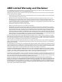
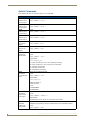
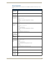
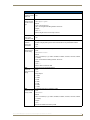
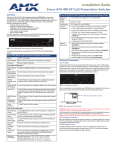
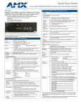
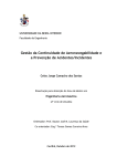
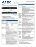
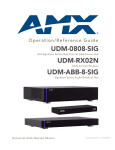
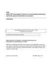
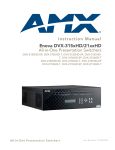
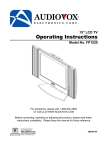
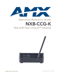
Enova AVX-400 Cat5 Presentation Switcher Operation/Reference Guide
Operation/Reference Guide
Enova
AVX-400
Cat5 Presentation Switcher
Cat5 Presentation Switchers
Initial Release: 11/17/2009
AMX Limited Warranty and Disclaimer
This Limited Warranty and Disclaimer extends only to products purchased directly from AMX or an AMX Authorized Partner which
include AMX Dealers, Distributors, VIP’s or other AMX authorized entity.
AMX warrants its products to be free of defects in material and workmanship under normal use for three (3) years from the date of
purchase, with the following exceptions:
•
Electroluminescent and LCD Control Panels are warranted for three (3) years, except for the display and touch overlay components are warranted for a period of one (1) year.
•
Disk drive mechanisms, pan/tilt heads, power supplies, and MX Series products are warranted for a period of one (1) year.
•
AMX lighting products are guaranteed to switch on and off any load that is properly connected to our lighting products, as long
as the AMX lighting products are under warranty. AMX also guarantees the control of dimmable loads that are properly connected to our lighting products. The dimming performance or quality there of is not guaranteed, impart due to the random combinations of dimmers, lamps and ballasts or transformers.
•
AMX software is warranted for a period of ninety (90) days.
•
Batteries and incandescent lamps are not covered under the warranty.
•
AMX AutoPatch Epica, Modula, Modula Series4, Modula CatPro Series and 8Y-3000 product models will be free of defects in
materials and manufacture at the time of sale and will remain in good working order for a period of three (3) years following the
date of the original sales invoice from AMX. The three-year warranty period will be extended to the life of the product (Limited
Lifetime Warranty) if the warranty card is filled out by the dealer and/or end user and returned to AMX so that AMX receives it
within thirty (30) days of the installation of equipment but no later than six (6) months from original AMX sales invoice date. The
life of the product extends until five (5) years after AMX ceases manufacturing the product model. The Limited Lifetime Warranty
applies to products in their original installation only. If a product is moved to a different installation, the Limited Lifetime Warranty
will no longer apply, and the product warranty will instead be the three (3) year Limited Warranty.
All products returned to AMX require a Return Material Authorization (RMA) number. The RMA number is obtained from the AMX
RMA Department. The RMA number must be clearly marked on the outside of each box. The RMA is valid for a 30-day period. After
the 30-day period the RMA will be cancelled. Any shipments received not consistent with the RMA, or after the RMA is cancelled, will
be refused. AMX is not responsible for products returned without a valid RMA number.
AMX is not liable for any damages caused by its products or for the failure of its products to perform. This includes any lost profits, lost
savings, incidental damages, or consequential damages. AMX is not liable for any claim made by a third party or by an AMX Authorized Partner for a third party.
This Limited Warranty does not apply to (a) any AMX product that has been modified, altered or repaired by an unauthorized agent or
improperly transported, stored, installed, used, or maintained; (b) damage caused by acts of nature, including flood, erosion, or earthquake; (c) damage caused by a sustained low or high voltage situation or by a low or high voltage disturbance, including brownouts,
sags, spikes, or power outages; or (d) damage caused by war, vandalism, theft, depletion, or obsolescence.
This limitation of liability applies whether damages are sought, or a claim is made, under this warranty or as a tort claim (including
negligence and strict product liability), a contract claim, or any other claim. This limitation of liability cannot be waived or amended by
any person. This limitation of liability will be effective even if AMX or an authorized representative of AMX has been advised of the
possibility of any such damages. This limitation of liability, however, will not apply to claims for personal injury.
Some states do not allow a limitation of how long an implied warranty last. Some states do not allow the limitation or exclusion of incidental or consequential damages for consumer products. In such states, the limitation or exclusion of the Limited Warranty may not
apply. This Limited Warranty gives the owner specific legal rights. The owner may also have other rights that vary from state to state.
The owner is advised to consult applicable state laws for full determination of rights.
EXCEPT AS EXPRESSLY SET FORTH IN THIS WARRANTY, AMX MAKES NO OTHER WARRANTIES, EXPRESSED OR
IMPLIED, INCLUDING ANY IMPLIED WARRANTIES OF MERCHANTABILITY OR FITNESS FOR A PARTICULAR PURPOSE. AMX
EXPRESSLY DISCLAIMS ALL WARRANTIES NOT STATED IN THIS LIMITED WARRANTY. ANY IMPLIED WARRANTIES THAT
MAY BE IMPOSED BY LAW ARE LIMITED TO THE TERMS OF THIS LIMITED WARRANTY. EXCEPT AS OTHERWISE LIMITED
BY APPLICABLE LAW, AMX RESERVES THE RIGHT TO MODIFY OR DISCONTINUE DESIGNS, SPECIFICATIONS, WARRANTIES, PRICES, AND POLICIES WITHOUT NOTICE.
AMX Software License and Warranty Agreement
•
LICENSE GRANT. AMX grants to Licensee the non-exclusive right to use the AMX Software in the manner described in this
License. The AMX Software is licensed, not sold. This license does not grant Licensee the right to create derivative works of the
AMX Software. The AMX Software consists of generally available programming and development software, product documentation, sample applications, tools and utilities, and miscellaneous technical information. Please refer to the README.TXT file on
the compact disc or download for further information regarding the components of the AMX Software. The AMX Software is subject to restrictions on distribution described in this License Agreement. AMX Dealer, Distributor, VIP or other AMX authorized
entity shall not, and shall not permit any other person to, disclose, display, loan, publish, transfer (whether by sale, assignment,
exchange, gift, operation of law or otherwise), license, sublicense, copy, or otherwise disseminate the AMX Software. Licensee
may not reverse engineer, decompile, or disassemble the AMX Software.
•
ACKNOWLEDGEMENT. You hereby acknowledge that you are an authorized AMX dealer, distributor, VIP or other AMX authorized entity in good standing and have the right to enter into and be bound by the terms of this Agreement.
•
INTELLECTUAL PROPERTY. The AMX Software is owned by AMX and is protected by United States copyright laws, patent
laws, international treaty provisions, and/or state of Texas trade secret laws. Licensee may make copies of the AMX Software
solely for backup or archival purposes. Licensee may not copy the written materials accompanying the AMX Software.
•
TERMINATION. AMX RESERVES THE RIGHT, IN ITS SOLE DISCRETION, TO TERMINATE THIS LICENSE FOR ANY REASON UPON WRITTEN NOTICE TO LICENSEE. In the event that AMX terminates this License, the Licensee shall return or
destroy all originals and copies of the AMX Software to AMX and certify in writing that all originals and copies have been
returned or destroyed.
•
PRE-RELEASE CODE. Portions of the AMX Software may, from time to time, as identified in the AMX Software, include PRERELEASE CODE and such code may not be at the level of performance, compatibility and functionality of the GA code. The
PRE-RELEASE CODE may not operate correctly and may be substantially modified prior to final release or certain features may
not be generally released. AMX is not obligated to make or support any PRE-RELEASE CODE. ALL PRE-RELEASE CODE IS
PROVIDED "AS IS" WITH NO WARRANTIES.
•
LIMITED WARRANTY. AMX warrants that the AMX Software (other than pre-release code) will perform substantially in accordance with the accompanying written materials for a period of ninety (90) days from the date of receipt. AMX DISCLAIMS ALL
OTHER WARRANTIES, EITHER EXPRESS OR IMPLIED, INCLUDING, BUT NOT LIMITED TO IMPLIED WARRANTIES OF
MERCHANTABILITY AND FITNESS FOR A PARTICULAR PURPOSE, WITH REGARD TO THE AMX SOFTWARE. THIS LIMITED WARRANTY GIVES LICENSEE SPECIFIC LEGAL RIGHTS. Any supplements or updates to the AMX SOFTWARE,
including without limitation, any (if any) service packs or hot fixes provided to Licensee after the expiration of the ninety (90) day
Limited Warranty period are not covered by any warranty or condition, express, implied or statutory.
•
LICENSEE REMEDIES. AMX's entire liability and Licensee's exclusive remedy shall be repair or replacement of the AMX Software that does not meet AMX's Limited Warranty and which is returned to AMX in accordance with AMX's current return policy.
This Limited Warranty is void if failure of the AMX Software has resulted from accident, abuse, or misapplication. Any replacement AMX Software will be warranted for the remainder of the original warranty period or thirty (30) days, whichever is longer.
Outside the United States, these remedies may not available. NO LIABILITY FOR CONSEQUENTIAL DAMAGES. IN NO
EVENT SHALL AMX BE LIABLE FOR ANY DAMAGES WHATSOEVER (INCLUDING, WITHOUT LIMITATION, DAMAGES
FOR LOSS OF BUSINESS PROFITS, BUSINESS INTERRUPTION, LOSS OF BUSINESS INFORMATION, OR ANY OTHER
PECUNIARY LOSS) ARISING OUT OF THE USE OF OR INABILITY TO USE THIS AMX SOFTWARE, EVEN IF AMX HAS
BEEN ADVISED OF THE POSSIBILITY OF SUCH DAMAGES. BECAUSE SOME STATES/COUNTRIES DO NOT ALLOW
THE EXCLUSION OR LIMITATION OF LIABILITY FOR CONSEQUENTIAL OR INCIDENTAL DAMAGES, THE ABOVE LIMITATION MAY NOT APPLY TO LICENSEE.
•
U.S. GOVERNMENT RESTRICTED RIGHTS. The AMX Software is provided with RESTRICTED RIGHTS. Use, duplication, or
disclosure by the Government is subject to restrictions as set forth in subparagraph ©(1)(ii) of The Rights in Technical Data and
Computer Software clause at DFARS 252.227-7013 or subparagraphs ©(1) and (2) of the Commercial Computer Software
Restricted Rights at 48 CFR 52.227-19, as applicable.
•
SOFTWARE AND OTHER MATERIALS FROM AMX.COM MAY BE SUBJECT TO EXPORT CONTROL. The United States
Export Control laws prohibit the export of certain technical data and software to certain territories. No software from this Site may
be downloaded or exported (i) into (or to a national or resident of) Cuba, Iraq, Libya, North Korea, Iran, Syria, or any other country to which the United States has embargoed goods; or (ii) anyone on the United States Treasury Department's list of Specially
Designated Nationals or the U.S. Commerce Department's Table of Deny Orders. AMX does not authorize the downloading or
exporting of any software or technical data from this site to any jurisdiction prohibited by the United States Export Laws.
This Agreement replaces and supersedes all previous AMX Software License Agreements and is governed by the laws of
the State of Texas, and all disputes will be resolved in the courts in Collin County, Texas, USA. For any questions concerning this Agreement, or to contact AMX for any reason, please write: AMX License and Warranty Department, 3000 Research
Drive, Richardson, TX 75082.
Table of Contents
Table of Contents
Overview ............................................................................................................1
Specifications............................................................................................................ 1
Wiring and Device Connections ..........................................................................3
AVX-400 Front and Rear Components...................................................................... 3
Front Panel Components .......................................................................................... 4
Source Select Button (SELECT)........................................................................................ 4
Source Inputs (INPUTS 1-4) ............................................................................................. 4
LINE IN ............................................................................................................................ 5
AXLINK ........................................................................................................................... 7
DEVICE DIP Switches ...................................................................................................... 8
RS232 .............................................................................................................................. 8
Configuration Port (PROG).............................................................................................. 8
Power Connector ............................................................................................................ 9
Preparing Captive Wires ................................................................................................. 9
Wiring a Power Connection........................................................................................... 10
Installing a Suppression Ferrite ..................................................................................... 10
Rear Panel Components.......................................................................................... 11
DISPLAY CONTROL....................................................................................................... 11
SPEAKER ....................................................................................................................... 12
LINE OUT ...................................................................................................................... 12
Composite Output (VIDEO)........................................................................................... 13
HD-15 Output Connectors ............................................................................................ 13
Mounting the Presentation Switcher ...................................................................... 14
Configuration ...................................................................................................15
AMX DCS Software................................................................................................. 15
Enabling Display Control............................................................................................... 17
Priority Switching .......................................................................................................... 18
Setting the Inactive Display Power Down ..................................................................... 18
Device Library Manager.......................................................................................... 19
Adding a Device to the Device Library.......................................................................... 20
Modifying Devices in the Device Library ....................................................................... 21
Importing a Device Library............................................................................................ 21
Renaming a Device........................................................................................................ 22
Updating Firmware ................................................................................................. 23
Programming ....................................................................................................25
AxLink Channels...................................................................................................... 25
AxLink Levels .......................................................................................................... 25
Enova AVX-400 Cat5 Presentation Switcher Operation/Reference Guide
v
Table of Contents
AxLink Commands .................................................................................................. 26
Serial Commands .................................................................................................... 27
vi
Enova AVX-400 Cat5 Presentation Switcher Operation/Reference Guide
Overview
Overview
The Enova AVX-400 Cat5 Presentation Switcher (FG1350-01) is a four input, multi-format active
presentation switcher with auxiliary line level audio input. The AVX-400 (FIG. 1) is a Cat5 switcher with basic
projector/display control via RS-232, but with external control of the switcher via RS-232 or AxLink. This
presentation switcher incorporates the following:
External serial or AxLink control
Projector or display control via RS-232
Integrated multi-format Cat5 audio/video switcher
Audio mixer with an auxiliary line input facility
Audio volume and tone control
Built-in audio amplifier
Front panel
Rear panel
FIG. 1 Enova AVX-400 Cat5 Presentation Switcher (front and rear panels)
The presentation switcher presents the respective output for the VGA/RGB, component, and composite video
sources. All sources remain in their native formats and resolutions. The selected video source is presented with
its related audio, and mixed with the auxiliary line input. Master volume of the program sound is available for
adjustment by external control.
The system is suitable for use within a 1-50m range (3.2'-150'). There is control for video gain and video
equalization for each input to compensate for cable length and allow optimization of each source. The
switchers contain a stereo 10W per channel built-in audio amplifier with 7-band graphic equalization.
Specifications
The following table lists the specifications for the presentation switcher:
AVX-400 Cat5 Presentation Switcher Specifications
Power
12VDC, 4.4A supply
See the Power Connector section on page 9 for information about current
draw.
Audio Amplifier
Stereo 10W per channel with 7-band graphic equalization
Enclosure
Metal with black matte finish
Enova AVX-400 Cat5 Presentation Switcher Operation/Reference Guide
1
Overview
AVX-400 Cat5 Presentation Switcher Specifications (Cont.)
Front Panel Components:
Source Select Button
1 button for toggling through the 4 inputs with each press
Source Select LED Indicators 4 LED indicators which show which source has been selected
Source Inputs (INPUTS 1-4)
4 RJ-45 connectors for source audio and video
Front Panel Components:
LINE IN Auxiliary Audio Input
1 3.5mm Phoenix (5-pin) connector for use with external audio equipment
such as radio microphones and mixers.
AxLink Device DIP Switches
1 set of 8 DIP switches for setting the address of an AxLink device
AxLink Port
1 3.5mm Phoenix (4-pin) connector that provides data to external control
devices and allows the AVX-400 to be controlled from a Master. A green
AxLink LED indicates the state of the AxLink port.
Note: The AVX-400-SP cannot be powered by this port or use the port to
power other devices.
RS-232 Control Port
1 3.5mm Phoenix (3-pin) connector that provides data to external control
devices and allows the AVX-400 to be controlled from RS232 controller.
Configuration Port (PROG)
1 type-B USB connector for configuring the switcher via DCS software.
Power Connector
1 3.5mm Phoenix (2-pin) connector
Rear Panel Components:
RS-232 Display Control
1 male DB9 connector used to control a projector or display from the
AVX-400-SP
Audio Amplifier Output
1 5.0mm Phoenix (4-pin) connector capable of delivering 2x10W into 8 ohm
variable stereo audio amplifier.
Line Level Audio Output
1 3.5mm Phoenix (5-pin) connector provides the mixed audio at Line Level
Composite Output
1 RCA (Y) connector for connecting to a display device
VGA/RGB Output
1 HD-15 connector for connecting to a display device
Component Output
1 HD-15 connector for connecting to a display device. You can use breakout
cable CC-HD15M-RCA3M (FG10-2170-03) to connect to 3 x RCA Phono
Sockets.
Operating Environment:
Storage Temperature: -10º C to 70º C (14º F to 158º F)
Operating Temperature: 0º C to 40º C (32º F to 104º F)
Operating Relative Humidity: 5% to 85% non-condensing
Dimensions (HWD):
1.75" (4.45cm) x 9" (22.86cm) x 6" (15.24cm) HWD
Weight:
2.57 lbs (1.17 kg)
Certifications:
FCC Class B, CE, and IEC60950
Included Accessories:
• 2 5-pin 3.5mm Phoenix connectors, for line-in/out (41-0336)
• 1 4-pin 3.5mm Phoenix connector, for AxLink (41-5047)
• 2 2-pin 5 mm Phoenix connectors, for speakers (41-0158-SA)
• 1 RS-232 3-pin 3.5mm Phoenix connector (41-0338)
• 1 PSN4.4, Power Supply, 4.4A, 3.5mm Phoenix, 13.5VDCA5 (FG423-45)
• Enova AVX-400 Presentation Switcher Installation Guide (93-1350-01)
• 1 Suppression Ferrite (04-0018-SA)
Optional Accessories:
• UPX-CN+A Component Universal Transmitter Wallplate (FG1402-52)
• UPX-CS+A Composite Universal Transmitter Wallplate (FG1402-50)
• UPX-RGB+A RGB Universal Transmitter Wallplate (FG1402-51)
• Surface Mount Kit (KA2250-40) with mounting bracket (62-2254-02)
• SP-08-AX 8-Button Keypad with AxLink (FG1311-08)
• CC-HD15 Male to HD-15 Male cable (FG10-2170-01)
• CC-HD15 Male to 3 RCA3 Male cable (FG10-2170-03)
2
Enova AVX-400 Cat5 Presentation Switcher Operation/Reference Guide
Wiring and Device Connections
Wiring and Device Connections
AVX-400 Front and Rear Components
FIG. 2 displays the components on the front panel of the AVX-400.
AxLink
Device
DIP Switches
Source
Select
Button
AxLink
Port
Auxiliary
Audio
Input
Source Inputs
Program
Port
RS-232
Control
Port
Power
Connector
FIG. 2 AVX-400 front panel components
FIG. 3 displays the components on the rear panel of the AVX-400.
Line Level
Audio Output
Display Control
Composite
Output
HD-15
Component
Connector
HD-15
RGB/VGA
Connector
Audio Amplifier Output
FIG. 3 AVX-400 rear panel components
Enova AVX-400 Cat5 Presentation Switcher Operation/Reference Guide
3
Wiring and Device Connections
Front Panel Components
The following sections describe the options on the front panel of the AVX-400.
Source Select Button (SELECT)
FIG. 4 Source Select button
The AVX-400 includes one source select button you can press repeatedly to select one of the four input
sources. When you press the SELECT button, the first input source is selected. Pressing it again selects the
next valid input, and so on. The LED indicator beside the selected input turns on to show which source you
have selected.
Source Inputs (INPUTS 1-4)
FIG. 5 Source Inputs
The Source inputs can accept video from devices such as PCs, DVD players, satellite receivers, and video
conference systems. You can use the Source Input ports to connect Cat5/5e/6 cables to the port on a wall input
plate which then connects to an input device via composite, component, or RGB/VGA connector. The LED
beside each port lights red when its associated port is active.
Use Cat5/5e/6 cable only for the source input connections. Using Cat5 crossover
cable may damage the presentation switcher.
The following table lists the pinouts, signals, and pairing associated with the Source Input connector.
Source Input RJ-45 Pinouts and Signals
Pin
4
Signals
Connections
Pairing
1 --------- 2
1
R+
1 --------- 1
2
R-
2 --------- 2
3
B+
3 --------- 3
4
G+
4 --------- 4
5
G-
5 --------- 5
6
B-
6 --------- 6
7
TX+
7 --------- 7
8
TX-
8 --------- 8
Color
Orange-White
Orange
3 --------- 6
Green-White
Blue
4 --------- 5
Blue-White
Green
7 --------- 8
Brown-White
Brown
Enova AVX-400 Cat5 Presentation Switcher Operation/Reference Guide
Wiring and Device Connections
FIG. 6 diagrams the RJ-45 pinouts and signals for the Source Input connector and cable.
FIG. 6 RJ-45 wiring diagram
When connecting to a wall input plate, use Cat5/5e/6 cable to connect from the source input on the switcher to
the RJ-45 connector on the wall input plate (FIG. 7).
Wall input plate RJ-45 connector
FIG. 7 Wall input plate connector
LINE IN
FIG. 8 LINE IN Input
The LINE IN input is capable of delivering audio to mix into the program sound. This input is designed for use
with external audio equipment such as radio microphones and mixers. Connect the positive and negative
terminals for the left and right channels on the source audio input to the labelled wire terminals on the
switcher. The center terminal on the switcher accepts a grounding wire. For unbalanced sources, you can use
the R+, L+, and Ground connections (FIG. 9). You can connect a microphone to this input using a
preamplifier.
Enova AVX-400 Cat5 Presentation Switcher Operation/Reference Guide
5
Wiring and Device Connections
Source and destination devices require either balanced (differential) or unbalanced (single-ended) connections.
FIG. 9 illustrates options for wiring between sources and input connectors and between output connectors and
the destinations. More than one option can be use in the same system.
AVX-400
source device
Balanced wiring
Unbalanced wiring
FIG. 9 Stereo 5-terminal wiring
FIG. 10 provides details for wiring from an audio input to a non-5 terminal audio source or destination, such as
an RCA connector. Positive and ground wires connect to the source or destination connector.
AVX-400
source device
FIG. 10 Non 5-terminal audio source and destination wiring
6
Enova AVX-400 Cat5 Presentation Switcher Operation/Reference Guide
Wiring and Device Connections
AXLINK
FIG. 11 AxLink Port
All AVX-400 units have an AxLink port and adjacent status LED (FIG. 11). This port allows the unit to be
controlled from any AxLink Master such as a NetLinx NI Controller. A green LED shows AxLink data
activity. When the AxLink port is operating normally, blink patterns include:
Off - No power, or the controller is not functioning properly.
1 blink per second - Normal operation.
3 blinks per second - AxLink bus error. Check all AxLink bus connections.
The AVX-400 cannot be powered by this port or use the port to power other devices.
To use the 4-pin 3.5 mm mini-Phoenix (female) captive-wire connector for data communication and power
transfer, the incoming PWR and GND cable from the 12 VDC-compliant power supply must be connected to
the AxLink cable connector going to the Integrated Controller. FIG. 12 shows the wiring diagram. Always use
a local power supply to power the Integrated Controller unit.
NI Master
Top view
Local 12+ VDC
power supply
(coming from an
external
power supply)
AVX-400
Top view
FIG. 12 4-pin mini-Phoenix connector wiring diagram (using external power source)
When you connect an external power supply, do not connect the wire from the PWR
terminal (coming from the external device) to the PWR terminal on the Phoenix
connector attached to the Controller unit. Make sure to connect only the AXM, AXP,
and GND wires to the Controller’s Phoenix connector when using an external power
supply.
Make sure to connect only the GND wire on the AxLink/PWR connector when using a separate 12 VDC
power supply. Do not connect the PWR wire to the AxLink connector’s PWR (+) opening.
Enova AVX-400 Cat5 Presentation Switcher Operation/Reference Guide
7
Wiring and Device Connections
DEVICE DIP Switches
ON
FIG. 13 DEVICE DIP Switches
The 8-position AxLink DEVICE DIP switch sets the AxLink identification number for your AxLink device.
Make sure the device number matches the number assigned in the software program. The following table
describes the values on the AxLink DEVICE DIP switch.
AxLink DEVICE DIP Switch Settings
Position
1
2
3
4
5
6
7
8
Value
1
2
4
8
16
32
64
128
If the device’s value is set to 0 (by positioning all DIP switches to the OFF setting), you can use AxLink serial
commands with your AxLink device.
RS232
FIG. 14 RS232 control port
The RS232 control port is a bi-directional serial port. The port uses a 3-pin 3.5mm Phoenix connector, and
supports 9600 baud communications only. When communicating via RS-232, connect the wiring as shown in
FIG. 15.
Serial
Device
GND
RX
TX
GND
TX
RX
AVX-400
FIG. 15 RS-232 wiring
The following table lists the default button commands when you connect an SP-08-AX 8-Button Keypad:
SP-08-AX 8-Button Keypad Defaults
8
Button
Default
1
Switch to Input 1
2
Switch to Input 2
3
Switch to Input 3
4
Switch to Input 4
5
Increase volume
6
Decrease volume
7
Hold for 3 seconds to turn on the programmed projector,
and hold 3 seconds again to turn it off.
8
Mute all (video and sound)
Enova AVX-400 Cat5 Presentation Switcher Operation/Reference Guide
Wiring and Device Connections
Configuration Port (PROG)
FIG. 16 Configuration port
The AVX-400 contains one low-speed type-B USB connection located on the front of the unit. Use a standard
USB cable to establish a connection between the device and your PC's USB port. This connection enables you
to program the switcher by using AMX DCS software. See the AMX DCS Software section on page 15 for
more information.
Power Connector
FIG. 17 Power connector
The AVX-400 uses a 12 VDC-compliant power supply to provide power to the switcher through the front
2-pin 3.5 mm mini-Phoenix power connector. Use the power requirements information described in the
product’s Specifications table to determine the power draw. The incoming PWR and GND cable from the
power supply must be connected to the corresponding locations within the power connector.
The AVX current draw with no input plates is 750mA. The following table lists the current draw for each type
of input wallplate you can connect to the AVX-400.
Wallplate Current Draw
Component
160mA
VGA
140mA
Composite
110mA
To illustrate, an AVX-400 with 2 VGA wallplates, 1 Component wallplate, and 1 Composite wallplate draws:
750 + 140 + 140 + 110 + 160 = 1.3A
The above equation does not take into account an audio source, which can increase
the draw by up to 1A depending on frequency and volume.
This unit should only have one source of incoming power.
Using more than one source of power to the Controller can result in damage to the
internal components and a possible burn out.
Apply power to the unit only after installation is complete.
Enova AVX-400 Cat5 Presentation Switcher Operation/Reference Guide
9
Wiring and Device Connections
Preparing Captive Wires
You will need a wire stripper and flat-blade screwdriver to prepare and connect the captive wires.
Never pre-tin wires for compression-type connections.
1. Strip 0.25 inch (6.35 mm) of insulation off all wires.
2. Insert each wire into the appropriate opening on the connector (according to the wiring diagrams and
connector types described in this section).
3. Tighten the screws to secure the wire in the connector. Do not tighten the screws excessively doing so
may strip the threads and damage the connector.
Wiring a Power Connection
To use the 2-pin 3.5mm mini-Phoenix connector with a 12 VDC-compliant power supply, the incoming PWR
and GND cables from the external source must be connected to their corresponding locations on the connector
(FIG. 18). Follow these steps to wire a power connection:
1. Insert the PWR and GND wires on the terminal end of the 2-pin 3.5 mm mini-Phoenix cable. Match the
wiring locations of the +/- on both the power supply and the terminal connector.
2. Tighten the clamp to secure the two wires. Do not tighten the screws excessively. Doing so may strip the
threads and damage the connector.
3. Verify the connection of the 2-pin 3.5 mm mini-Phoenix to the external 12 VDC-compliant power supply.
PWR +
Power Supply
GND FIG. 18 2-pin mini-Phoenix connector wiring diagram (direct power)
Installing a Suppression Ferrite
If you are in a location with 240V of power, you must clip the supplied Suppression
Ferrite around the Power cable (no tools required).
1. Release the latch to open
the plastic enclosure.
2. Insert the power cable
and close the enclosure.
3. Installation complete.
FIG. 19 Installing the Suppression Ferrite
10
Enova AVX-400 Cat5 Presentation Switcher Operation/Reference Guide
Wiring and Device Connections
Rear Panel Components
The following sections describe the options on the rear panel of the AVX-400.
DISPLAY CONTROL
FIG. 20 DISPLAY CONTROL connector
The DISPLAY CONTROL connector is used for controlling a display device such as a projector or large
screen LCD. FIG. 21 shows the connector pinouts for the rear DISPLAY CONTROL connector. The
DISPLAY CONTROL port supports most standard RS-232 communication protocols for data transmission.
This figure gives a visual representation of the wiring specifications for the DISPLAY CONTROL connector.
1 2 3 4 5
RS-232 pinouts (male connector)
Pin 2: RX signal
Pin 3: TX signal
Pin 5: GND
6 7 8 9
FIG. 21 RS-232 DB9 (male) connector pinouts for the rear Display Control connector
The table below provides information about the connector pins, signal types, and signal functions. This table’s
wiring specifications are applicable to the rear DISPLAY CONTROL connector on the switcher.
RS-232 Display Control Wiring Specifications
Pin
Signal
Function
RS-232
1
2
RXD
Receive data
X
3
TXD
Transmit data
X
GND
Signal ground
X
4
5
6
7
8
9
Enova AVX-400 Cat5 Presentation Switcher Operation/Reference Guide
11
Wiring and Device Connections
SPEAKER
FIG. 22 SPEAKER output
The SPEAKER output is capable of delivering 2x10W into 8 ohm amplified variable stereo audio. The output
level can be adjusted by serial or AxLink commands.
LINE OUT
FIG. 23 LINE OUT output
The LINE OUT output provides the mixed program and line input sources at a variable line level output. It is
designed for use with external audio equipment such as induction loop systems, recording devices, or video
conferencing systems.
Destination devices require either balanced (differential) or unbalanced (single-ended) connections. FIG. 24
illustrates options for wiring between output connectors and the destinations.
destination device
AVX-400
Balanced wiring
Unbalanced wiring
FIG. 24 Stereo 5-terminal wiring
12
Enova AVX-400 Cat5 Presentation Switcher Operation/Reference Guide
Wiring and Device Connections
Composite Output (VIDEO)
FIG. 25 Composite output
The composite output enables you to use a composite cable (RCA Y) to send video to a display device like a
projector. Attach the composite cable to the composite video connector on the rear of the presentation switcher
and run the other end of the cable to the Composite connector (normally yellow) on the display device or to a
Composite wall input plate. If you connect the port to a wall input plate, use an RJ-45 cable to connect the port
on the rear of the wall input plate to one of the source input ports on the front of the switcher.
HD-15 Output Connectors
FIG. 26 HD-15 Output connectors
Each AVX-400 has two HD-15 output connectors. The outputs enable you to use an HD-15 to COMPONENT
or HD-15 to RGB/VGA cable to send video to a display device such as a projector or large screen monitor. The
output device displays video from source input devices routing through the AVX-400-SP. There is one output
each for COMPONET and RGB/VGA sources. The following table lists the pinout configuration for HD-15
connector to RGB/VGA connectors:
Video Output HD-15 Connector Pinouts
Pin
Signal
Function
1
Red
Red signals
2
Green
3
Blue
4
N/C
Green signals
Blue signals
5
6
RGND
Red analog ground
7
GGND
Green analog ground
8
BGND
Blue analog ground
SGND
Synchronization analog ground
1
2 3 4 5
6 7 8 9 10
11 12 13 14 15
9
10
11
12
13
HSYNC
Horizontal synchronization signal
14
VSYNC
Vertical synchronization signal
15
Enova AVX-400 Cat5 Presentation Switcher Operation/Reference Guide
13
Wiring and Device Connections
You can use breakout cable CC-HD15M-RCA3M (FG10-2170-03) to connect to 3 x
RCA Phono Sockets.
The following table lists the pinout configuration for HD-15 connector to Component connectors:
HD-15 to Component Pinouts
VGA Pin
Component Signal
1
Pr signal
2
Y signal
3
Pb signal
4
5
6
Pr - Return
7
Y - Return
8
Pb - Return
9
10
11
12
13
14
15
Mounting the Presentation Switcher
The AVX-400 can be mounted onto a flat surface or mounted under a table. Attach the mounting brackets from
the optional mount kit (KA2250-40) to the sides of the switcher as shown in FIG. 27 to mount the unit to any
flat surface. FIG. 27 displays the mounting brackets set to attach to the underside of a table. To surface-mount
the unit, attach the mounting brackets with the flat side toward the bottom of the unit.
FIG. 27 AVX-400 presentation switcher with optional mounting brackets.
14
Enova AVX-400 Cat5 Presentation Switcher Operation/Reference Guide
Configuration
Configuration
AMX DCS Software
You can configure the AVX-400 and its functionality by using AMX DCS software (FIG. 28). The top of the
window displays the device image of the front panel of the Enova AVX-400, and displays which inputs are
valid by highlighting the source input. Clicking on a highlighted port on the device image changes the active
input. The active source input is indicated by the illuminated red LED beside the source input.
Highlighted port indicates
valid wallplate connection and type
Non-highlighted port
indicates no wallplate connection
FIG. 28 AMX DCS main screen
The bottom half of the window features the Device Setup options. The Device Setup area consists of three
tabs: Input, Audio and Display. The Input tab (FIG. 28) enables you to select a source input and adjust its
audio and video settings. The following options appear on the Input tab:
Input Tab Options
Active Input
Click each button to view the corresponding audio and video settings for the
input device.
Audio Attenuation
Use the slider to set the attenuation of the audio for the selected input. You can
preset the attenuation between the range of +24dB to -100dB.
Video Gain
Use the sliders to set the red, blue, and green levels for the video output of the
selected input. You can set each individual level between 0 and 100%.
Video EQ
Use the slider to set the equalization of the video for the selected input. You
can set the level between 0 and 100%.
Default Settings
Resets the Audio Attenuation, Video Gain, and Video EQ to their default
values.
Enova AVX-400 Cat5 Presentation Switcher Operation/Reference Guide
15
Configuration
The Audio tab (FIG. 29) enables you to adjust its audio in and out settings.
FIG. 29 Device Setup - Audio tab
The following options appear on the Audio tab:
Audio Tab Options
Auxiliary In - Attenuation
Use the slider to preset the attenuation of the audio for the auxiliary in device.
You can set the attenuation between the range of +24dB to -100dB.
Balance Out - Volume
Use the slider to preset the volume of the audio for the balance out device. You
can set the volume between the range of +24dB to -100dB.
Amplifier Out - Volume
Use the slider to preset the volume of the audio for the amplifier out device.
You can set the volume between the range of +24dB to -100dB.
Amplifier Out - Equalizer
Use the sliders to set the equalizer settings for the amplifier out device. You
can set the levels for the 100Hz, 250Hz, 500Hz, 1KHz, 2.5 KHz, 5KHz, and
10KHz frequencies. You can set each level between the range of +20dB to
-20dB.
Center All
Press this button to reset all Amplifier Out settings to 0dB.
The Display tab (FIG. 30) enables you to select a display output and establish input display settings.
FIG. 30 Device Setup - Display tab
16
Enova AVX-400 Cat5 Presentation Switcher Operation/Reference Guide
Configuration
The following options appear on the Display tab:
Display Tab Options
Enabled
Click the check box to enable display control. Display control enables you to
select a display to use for the output from your source inputs. Enabling display
control makes the options for Make, Type, Model, and Display Power Down
available.
Make
Select the manufacturer of the device you want to use.
Type
Select the type of device you want to use.
Model
Select the device model you want to use.
Switching Mode
Click an option button to indicate the method you want to use to switch
between source inputs. You can choose from Take-over Mode, Toggle Mode,
and Priority Switching.
Take-over Mode
With Take-over mode, if you press the button on a wallplate connected to
source input 1, then source input 1 becomes the active input. The same
applies to source inputs 2, 3, and 4.
Toggle Mode
With toggle mode, if you press the button on any of the wallplates, then the
selected video input changes to the next available input. For example, if you
have all four inputs connected to video sources, pressing any button on any
wallplate causes the active input to toggle from 1 to 2 to 3 to 4 to 1. If you only
have inputs 1, 2, and 3 connected, the toggle sequence will be 1 to 2 to 3 to 1.
Priority Switching
Enables you to establish a priority order for displaying each input. The input
device with the highest priority will always be sent to the output display as long
as the input device remains powered on. When the power to the highest
priority input device is turned off, the signal from the next active input device
appears on the output display. These options are not available unless you
select Priority Switching as the Switching Mode. See the Priority
Switching section on page 18 for more information.
Disable Wall Plate Buttons
Click the check box to disable source input switching via wallplate button. With
this option enabled, you cannot change inputs while in take-over or toggle
modes, and you cannot power up or power down the display device. This
option disables all wallplate button functions.
Display Power Down
Use the sliders to set the number of hours, minutes, or seconds (or some
combination of the three) before the display device powers down. Using the
Hours slider disables the Seconds slider. Set the time to 0 to disable power
down.
Program Device
Sends the current configuration to the presentation switcher. You must click
this button for any configuration changes to take effect.
Enabling Display Control
Display control enables you to select a display to use for the output from your source inputs. A display can be
any type of video output device. After enabling display control, you can select a make, type, and model of
display. If your display is not available from the options menus, see the Device Library Manager section on
page 19 for information on adding your specific device to the device library. Perform these steps to enable
display control:
1.
2.
3.
4.
Click the Display tab on the AMX DCS window.
Click the Enabled check box to enable display control.
Select a Make, Type, and Model display from their respective fields.
Click Program Device to send the display device’s commands to the presentation switcher.
Enova AVX-400 Cat5 Presentation Switcher Operation/Reference Guide
17
Configuration
Priority Switching
Priority switching enables you to establish a priority order for displaying each input device. The input device
with the highest priority will always be sent to the output display as long as the input device remains powered
on. When the power to the highest priority input device is turned off, the signal from the next active input
device appears on the output display.
For example, you have a DVD player set at priority 1, a PC at priority 2, and a VCR at priority 3. If the PC is
always powered on, it’s output is sent to the display provided the DVD player is currently powered off. When
the DVD player is powered on, its output is immediately sent to the display. Powering off the DVD player
returns the PC’s output to the display. The VCR’s output is only sent to the display if it is powered on, and the
DVD player and PC are both powered off.
Perform these steps to set up priority switching:
1. In the Device Setup area, click the Display tab (FIG. 30).
2. Click the Priority Switching option button in the Switching Mode section.
3. Use the options menus in the Priority Switching area to indicate the priority order for each input device.
The number you select from the drop-down menu is the source input number on the presentation switcher.
For example, if you want source input 3 to have the highest priority, select 3 from the first menu.
4. Click Program Device to send the new settings to the presentation switcher.
Setting the Inactive Display Power Down
You can use the DCS software to set an amount of time for a display to be inactive before it shuts down to save
power. Perform these steps to set the inactive display power down:
1. Click the Display tab on the AMX DCS window.
2. Enable display control. See the Enabling Display Control section on page 17 for more information.
3. Use the Hours, Minutes, and Seconds sliders to indicate the amount of time you want the display to be
inactive before powering down.
4. Click Program Device for the changes to take effect.
18
Enova AVX-400 Cat5 Presentation Switcher Operation/Reference Guide
Configuration
Device Library Manager
The Device Library Manager (FIG. 31) enables you to add, import, and modify information about individual
devices you can configure with DCS software. You can modify the device's serial connection settings and
provide hexadecimal values, where needed, for executable and status commands. The Device Library Manager
is accessible by selecting Device Library Manager from the File menu on the main DCS window.
FIG. 31 Device Library Manager
The following options appear on the Device Library Manager window
Device Library Manager Options
Device Selection
Device Filter
The Device Filter option opens to reveal three filtering options to help narrow
your search for a specific device. You can filter by Manufacturer, Device Type,
or Communications.
Add
Add a new device to the library. The Manufacturer can be a new manufacturer
or you can select a previously-defined entry from the drop-down list. Similarly,
the Device Type can be a new entry or you can select a previously-defined
entry from the drop-down list. Manufacturer and Device Model entries are
limited to 20 characters while Device Type is limited to 40 characters. Once the
device is added it will be populated and selected in the library tree.
Delete
Delete the selected device.
Sort
Sort the devices alphabetically.
Import
Allows you to import Novara or Solecis legacy library files (one-by-one) and
add their device definitions to the library. You can also import a previously
exported.xml library file.
Export
Allows you to select an existing device model from the tree and export its
definition to a file in .xml format. This feature allows you to share devices with
others. Once exported you can import the definition and add it to the library
(assuming it does not already exist).
Enova AVX-400 Cat5 Presentation Switcher Operation/Reference Guide
19
Configuration
Device Library Manager Options (Cont.)
Device Definition
Selected Model
The name of the selected device. This information is view-only.
Communications Type
The type of connection for the device. A different set of commands can be
saved for each communication type. RS-232 and IP communications have a
commands and status section whereas Infrared has only a command section.
RS-232 is the only option available for the AVX-400 presentation switcher.
Serial Connection Settings
Displays the Baud Rate, Data Bits, Data Format, Flow Control, Parity, and Stop
Bits for the device. You can change most of these options, if necessary. You
cannot change any field that appears dimmed.
Cmd Data (ASCII)
When you select a record from the commands/status table, this field shows the
ASCII representation of the data. This information is view-only, however, you
can select and copy the information.
Commands
Lists the available executable commands for the current device. If the device
has a compatible hexadecimal value for an individual command, the
hexadecimal value appears in the Data column. You can enter a value for each
command in the Data column, if available. Consult the manual included with
your device for more information.
Status
Lists the available status commands for the current device. If the device has a
compatible hexadecimal value for an individual command, the hexadecimal
value appears in the Data column. You can enter a value for each command in
the Data column, if available. Consult the manual included with your device for
more information.
Add
Adds a space for a new command in the above list. You can add the name of
the command and its hexadecimal value in the Name and Data fields,
respectively.
Delete
Deletes the selected command.
Cut
Removes the selected command from the command list and stores its
information on the local clipboard for copying.
Copy
Copies the selected command to the local clipboard for later retrieval.
Paste
Inserts the data on the local clipboard into the selected location.
Adding a Device to the Device Library
If the provided device library does not contain the device you are using, you can add the device to the library
manually. Perform the following steps to add a device to the device library:
1. From the File menu, select Device Manager Library. The Device Library Manager window opens.
2. In the Device Selection area, click the Add button. The Add Device dialog box opens (FIG. 32).
FIG. 32 Add Device dialog box
20
Enova AVX-400 Cat5 Presentation Switcher Operation/Reference Guide
Configuration
3.
4.
5.
6.
From the Manufacturer options menu, select a device manufacturer.
From the Device Type options menu, select the type of device you want to add.
Enter the name of the device in the Device Model field.
Click Add Device to add the device to the device library.
Modifying Devices in the Device Library
To modify a device's connection and command information, perform the following steps:
1. Select the device from the Device Selection tree. Its connection and command information appears in the
right pane.
2. Change the device's serial connection settings by clicking the individual option and selecting a new value
from the available list.
3. For any commands that require programming, click the field under the Data column for the corresponding
command, and enter the hexadecimal code required for the command. Consult the manual included with
your device for more information.
Importing a Device Library
1. From the File menu, select Device Manager Library. The Device Library Manager window opens.
2. In the Device Selection area, click the Import button.
3. Navigate to a directory containing Novara (*.plr, *.prr) or Solecis (*.txt) device libraries and select a
library file. The Import Legacy Library dialog box opens (FIG. 33).
FIG. 33 Import Legacy Library dialog box
4. Select the libraries your want to import, and click Import.
If any of the fields in the device library are undefined, you must rename the device to
define all fields before importing the library. See the Renaming a Device section on
page 22 for more information.
5. Click OK to confirm the libraries have been imported. The devices now appear in the Device Selection
list.
Enova AVX-400 Cat5 Presentation Switcher Operation/Reference Guide
21
Configuration
Renaming a Device
When importing a device library, if any of the fields in the device library are undefined, you must rename the
device to define all fields before importing the library.
1. Import a device library that contains undefined fields.
2. Right-click the device with undefined fields, and select Rename Device(s). The Rename Device Libraries
dialog box opens (FIG. 34).
FIG. 34 Rename Device Libraries dialog box
3. Enter the appropriate information in the undefined fields.
4. Click Rename. The Rename Device Libraries dialog box closes, and you can now import the device
library.
22
Enova AVX-400 Cat5 Presentation Switcher Operation/Reference Guide
Configuration
Updating Firmware
AMX DCS software provides a simple interface for updating your AVX-400 with the latest available version
of firmware. You must use a .bin file to upgrade the firmware through AMX DCS software. The latest
firmware files can be found at the Tech Center at www.amx.com.
You can access the Firmware Update tool by selecting Enova Firmware Update from the File menu in the
DCS software. Selecting this option opens the Enova Firmware Update window (FIG. 35)
FIG. 35 Enova Firmware Update window
Enova AVX-400 Cat5 Presentation Switcher Operation/Reference Guide
23
Configuration
The following options appear on this window:
Enova Firmware Update Window Options
Go to AMX.com
Click to open a browser and navigate to AMX.com. At AMX.com, you can
download the latest firmware for the device.
Current Firmware Version
Displays the current firmware version for the device. This information is
view-only.
Device Model
The device model of the unit you are updating. This information is view-only.
Select File
Click to browse and locate the latest firmware file on a local or network drive.
Loaded File
The latest firmware file. This information only appears after you select firmware
file to use for updating. This information is view-only.
File Size
The size of the loaded firmware file. This information is view-only.
Update
Click to begin updating the firmware for the device.
Status
The current state of the firmware update process. This information is view-only.
Bytes Updated
The current number of bytes of data that have been updated. This information
is view-only.
Cancel Update in Progress
Click to cancel the current firmware update. This button is only active when a
firmware update is in progress.
Close
Closes the window.
Perform these steps to update the firmware for your device:
1. From the File menu, select Enova Firmware Update. The Enova Firmware Update window opens
(FIG. 35).
2. Click Go to AMX.com. A web browser opens and navigates to www.amx.com.
3. Click Tech Center on the main page at AMX.com.
4. Locate and download the latest firmware version (.bin) for your device. Make note of the location to
which you save the firmware file. When the download is complete, return to the Enova Firmware update
window.
5. Click Select File, navigate to the location the firmware file was saved, and select the file.
6. Click Update. The firmware for the device is updated with the latest version.
7. Click Close to close the window and return to the AMX DCS window.
24
Enova AVX-400 Cat5 Presentation Switcher Operation/Reference Guide
Programming
Programming
AxLink Channels
Each AxLink device contains 255 channels numbered 1-255. The AxLink channels for the AVX-400-SP
are defined in the table below.
AxLink Channels
Channel
Description
24
Amplifier volume up when the channel is on.
25
Amplifier volume down when the channel is on.
26
Amplifier mute toggles when the channel turns on.
124
Balanced volume up when the channel is on.
125
Balanced volume down when the channel is on.
126
Balanced mute toggles when the channel turns on.
200
Balanced mute when the channel is on.
210
Video mute toggles when the channel turns on.
211
Video mute when the channel is on.
AxLink Levels
Each AxLink device contains 8 levels numbered 1-8. Levels are a means of applying a value to a physical
element on the device. The AxLink Levels for the AVX-400-SP are defined in the table below.
AxLink Levels
Level
Description
1
Amplifier volume
2
Balanced volume
3
Input 1 attenuation
4
Input 2 attenuation
5
Input 3 attenuation
6
Input 4 attenuation
7
Auxiliary input attenuation
Enova AVX-400 Cat5 Presentation Switcher Operation/Reference Guide
25
Programming
AxLink Commands
The following table lists the AxLink commands for the AVX-400:
AxLink Commands
CI1O1
Sets the active
input to input 1.
CI2O1
Sets the active
input to input 2.
CI3O1
Sets the active
input to input 3.
CI4O1
Sets the active
input to input 4.
DOF
Turns off the
display
DON
Turns on the
display
Syntax:
SEND_COMMAND "’CI1O1’"
Syntax:
SEND_COMMAND "’CI2O1’"
Syntax:
SEND_COMMAND "’CI3O1’"
Syntax:
SEND_COMMAND "’CI4O1’"
Syntax:
SEND_COMMAND "’DOF’"
Syntax:
SEND_COMMAND "’DON’"
?DST
Returns the current display status.
Queries the
display status
Syntax:
SEND_COMMAND "’?DST’"
Sample Output:
"DST-<A|B|C|D|E>"
A = power: (0=unknown, 1=on, 2=off, 3=warming, 4=cooling)
B = input: (0=unknown, 1=PC, 2=component, 3=composite)
C = lamp time: (0=unknown)
D = filter time: (0=unknown)
E = temperature: (0=unknown)
?GCT
Returns the connected input types.
Queries the
connected input
types
Syntax:
SEND_COMMAND "’?GCT’"
Sample Output:
"GCT-<A|B|C|D>"
ABCD are inputs 1-4.
0=No connection
1=PC
2=COMPONENT
3=COMPOSITE
?INPUT-1
Returns the current active source input.
Queries the
current active
source input.
Syntax:
SEND_COMMAND "’?INPUT-1’"
Sample Output:
"SWITCH-LALLI<x>O1" where <x> is the source input number.
SSW
Simulates
pressing the
select switch.
26
Pressing the source select button activates the next valid source input. This command
simulates a single pressing of the source select button on the presentation switcher.
Syntax:
SEND_COMMAND "’SSW’"
Enova AVX-400 Cat5 Presentation Switcher Operation/Reference Guide
Programming
Serial Commands
The following table lists the serial commands for the AVX-400. All commands are followed by a carriage
return.
Serial Commands
AMT
Toggle amplifier
mute
ASM
Turns on the
amplifier mute
Syntax:
AMT
Syntax:
ASM
ATA
Sets the auxiliary input attenuation to the specified level.
Set the auxiliary
input attenuation
Syntax:
ATA=<attenuation>
Variable:
attenuation = the attenuation setting between -100 and 24
Example:
ATA=12
ATI
Sets the attenuation for a source input to a specific level.
Set source input
attenuation
Syntax:
ATI<input>=<attenuation>
Variable:
input = source input (1-4)
attenuation = the attenuation setting between -100 and 24
Example:
ATI3=12
Sets the attenuation on source input 3 to 12.
ATT?
Returns the attenuation level for all channels.
Queries for the
attenuation levels
for each channel
Syntax:
AUM
Syntax:
Turns off the
amplifier mute
BGN
Sets the blue gain
level for a source
input
ATT?
AUM
Syntax:
BGN<input>=<gain>
Variable:
input = source input (1-4)
gain = the blue gain level setting between 0 and 100
Example:
BGN2=50
Sets the blue gain level on source input 2 to 50%.
BMT
Toggle the
balanced mute
BSM
Turns on the
balanced mute
BUM
Turns off the
balanced mute
Syntax:
BMT
Syntax:
BSM
Syntax:
BUM
Enova AVX-400 Cat5 Presentation Switcher Operation/Reference Guide
27
Programming
Serial Commands (Cont.)
DOF
Turns off the
display
DON
Turns on the
display
Syntax:
DOF
Syntax:
DON
DST?
Returns the current display status.
Queries the
display status
Syntax:
DST?
Sample Output:
"DST->A|B|C|D|E>"
A = power: (0=unknown, 1=on, 2=off, 3=warming, 4=cooling)
B = input: (0=unknown, 1=PC, 2=component, 3=composite)
C = lamp time: (0=unknown)
D = filter time: (0=unknown)
E = temperature: (0=unknown)
FWV?
Returns the current firmware version.
Queries the
firmware version
Syntax:
GCT?
Returns the connected input types.
Queries the
connected input
types
Syntax:
FWV?
GCT?
Sample Output:
"GCT-<A|B|C|D>"
ABCD are inputs 1-4.
0 = No connection
1 = PC
2 = COMPONENT
3 = COMPOSITE
GGN
Sets the green
gain level for a
source input
Syntax:
GGN<input>=<gain>
Variable:
input = source input (1-4)
gain = the green gain level setting between 0 and 100
Example:
GGN1=25
Sets the green gain level on source input 1 to 25%.
INP
Activates the indicated source input.
Set the current
source input
Syntax:
INP<input>
Variable:
input = source input (1-4)
Example:
INP1
Activates source input 1.
28
INP?
Returns the current source input.
Queries the
current active
source input
Syntax:
INP?
Enova AVX-400 Cat5 Presentation Switcher Operation/Reference Guide
Programming
Serial Commands (Cont.)
MUT
Toggles the audio/
video mute
RGN
Sets the red gain
level for a source
input
Syntax:
MUT
Syntax:
RGN<input>=<gain>
Variable:
input = source input (1-4)
gain = the red gain level setting between 0 and 100
Example:
RGN3=75
Sets the red gain level on source input 3 to 75%.
SMT
Turns on the
audio/video mute
SSW
Simulates
pressing the
select switch
Syntax:
SMT
Pressing the source select button activates the next valid source input. This command
simulates a single pressing of the source select button on the presentation switcher.
Syntax:
SSW
TON
Set an individual tone band to a specified level.
Set tone band to
specific setting
Syntax:
TON<band>=<level>
Variable:
band = tone band (1-7): (1=100Hz, 2=250Hz, 3=500Hz, 4=1KHz, 5=2.5 KHz, 6=5KHz,
7=10KHz)
level = the decibel level setting between -20 and 20
Example:
TON4=-6
Sets the 1KHz tone band to -6dB.
TON?
Returns the current tone band settings.
Queries the
current tone band
settings
Syntax:
?TON
Sample Output:
1=18dB
2=10dB
3=2dB
4=-6dB
5=1dB
6=10dB
7=15dB
TON+
The specified tone band increases by 0.5dB.
Increase the tone
band by 0.5dB
Syntax:
TON<band>+
Variable:
band = tone band (1-7): (1=100Hz, 2=250Hz, 3=500Hz, 4=1KHz, 5=2.5 KHz, 6=5KHz,
7=10KHz)
Example:
TON3+
Increases the 500Hz tone band by 0.5dB.
Enova AVX-400 Cat5 Presentation Switcher Operation/Reference Guide
29
Programming
Serial Commands (Cont.)
TON-
The specified tone band decreases by 0.5dB.
Decrease the tone Syntax:
band by 0.5dB
TON<band>Variable:
band = tone band (1-7): (1=100Hz, 2=250Hz, 3=500Hz, 4=1KHz, 5=2.5 KHz, 6=5KHz,
7=10KHz)
Example:
TON6Decreases the 5KHz tone band by 0.5dB.
UMT
Turns off the
audio/video mute
VEQ
Syntax:
UMT
Syntax:
Sets the video EQ
VEQ<input>=<eq>
for the source
Variable:
input
input = source input (1-4)
eq = the EQ level setting between 0 and 100
Example:
VEQ4=25
Sets the EQ level on source input 4 to 25%.
VEQ?
Returns all video EQ values for all source inputs.
Queries the video
EQ values for all
inputs
Syntax:
VEQ?
Sample Output:
1=25
2=35
3=50
4=0
VGN?
Returns the video gain values for all source inputs.
Queries the video
gain values for all
inputs
Syntax:
VLA
Sets the amp volume to a specified setting in decibels.
Set amp volume
Syntax:
VGN?
VLA=<volume>
Variable:
volume = the amp volume level setting between -100 and 24dB
Example:
VLA=20
Sets the balance out volume level to 20dB.
VLA+
Increase amp
volume by 0.5dB
VLADecrease amp
volume by 0.5dB
30
Syntax:
VLA+
Syntax:
VLA-
Enova AVX-400 Cat5 Presentation Switcher Operation/Reference Guide
Programming
Serial Commands (Cont.)
VLB
Sets the balance out volume to a specified setting in decibels.
Set balance out
volume
Syntax:
VLB=<volume>
Variable:
volume = the balance out volume level setting between -100 and 24dB
Example:
VLB=11
Sets the balance out volume level to 11dB.
VLB+
Increase balance
out volume by
0.5dB
VLBDecrease balance
out volume by
0.5dB
VMT
Toggle video mute
Syntax:
VLB+
Syntax:
VLB-
Syntax:
VMT
VOL
Sets amp and balance out volume to the same setting.
Sets amp and
balance out
volume
Syntax:
VOL=<volume>
Variable:
volume = the volume level setting between -100 and 24dB
Example:
VOL=5
Sets the volume level to 5dB.
VOL?
Returns the current volume levels.
Queries the
current amp and
balance out
volume levels.
Syntax:
VOL?
Sample Output:
A=20dB
B=11dB
VOL+
Increases the
volume by 0.5dB
VOLDecreases the
volume by 0.5dB
VSM
Turns on the
video mute
VUM
Turns off the video
mute
Syntax:
VOL+
Syntax:
VOLSyntax:
VSM
Syntax:
VUM
Enova AVX-400 Cat5 Presentation Switcher Operation/Reference Guide
31
Programming
32
Enova AVX-400 Cat5 Presentation Switcher Operation/Reference Guide
Programming
Enova AVX-400 Cat5 Presentation Switcher Operation/Reference Guide
33
11/09 ©2009 AMX. All rights reserved. AMX and the AMX logo are registered trademarks of AMX. AMX reserves the right to alter specifications without notice at any time.
It’s Your World - Take Control™
3000 RESEARCH DRIVE, RICHARDSON, TX 75082 USA • 800.222.0193 • 469.624.8000 • 469-624-7153 fax • 800.932.6993 technical support • www.amx.com