1
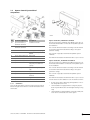
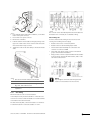
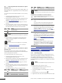
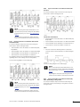
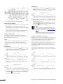
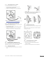
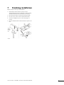
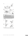
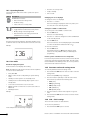
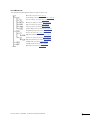
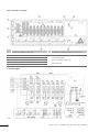
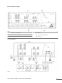
2. Press, without turning, with a thin screwdriver, on the white
button of the quick connector.
The controller senses automatically where the thermostats and
the actuators are connected, this is called auto linking.
3. Insert a wire in the quick connector.
Auto linking rules
4. Remove the screwdriver.
In order to make the auto linking of the controller to work
correctly, the following restrictions apply:
5. Lead the cables from the actuators through openings in the
upper row of cable entries in the controller and connect the
wires as described in steps 3. and 4.
6. Tighten the screws of the cable clamps to fix the thermostat
cable.
A Cable entries and cable clamps for thermostats
B Cable entries for actuators
•
•
•
Actuators must not be connected in parallel
•
There must never be any empty connector row between
groups of thermostats and actuators
•
Empty connector rows are only allowed after the last actuator
in the last group of thermostat and actuators, that is in the
end of the connector field
Actuators must not be linked with jumper cables
The first thermostat must always be connected to the
controller on connector row 01
NOTE!
Any disregard to follow the auto linking rules will
result in erroneous function of the controller.
C Cable entries and cable clamps for heating/cooling
relay, timer, and condense sensor
D Cable entries and cable clamps for 230 V AC
compartment
4.3.2
Auto linking
One thermostat can control of several actuators.
In the example below, the thermostat #01 is connected to the
controller on connector row 01. All actuators on rows 01 to 04 are
controlled from the same thermostat.
The next thermostat, #05, controls the actuators on rows 05 to
11 and thermostat #12 controls the actuator on row 12.
UPONOR CONTROL SYSTEM WIRED - INSTALLATION AND OPERATION MANUAL
11