1
Installing and Connecting the Panel PC 670/870
11/01
Installation cut-out
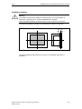
When selecting the installation cut-out, ensure that the switching cabinet/panel
contains reinforcement bars to stabilize the plate. If necessary, install such
reinforcement bars.
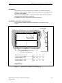
An installation cut-out is required corresponding to the following diagram:
2 to 6
2
H+1
B+1
T+1
Unit depth T
Installation cut-out
B
H
PC 670
PC 870
Panel PC 670/870, 12", Keys
Panel PC 670/870, 15", Keys
450
450
295 ± 0,5
326 ± 0,5
114
142
202
227
Panel PC 670/870, 12", Touch
Panel PC 670/870, 15", Touch
368
450
290
290
–
137
–
229
Figure 1–3
Unit depth T
All figures in mm.
Installation Cut-out for Standard Installation
Specifications without the CD-ROM option.
Note
Ensure sufficient air volume for heat transportation within the switching
cabinet/panel. There must be at least 100 mm free space around the
Panel PC 670/870. 10 mm are permissible on the rear side.
Also ensure sufficient free space to pull out the Panel PC 670/870 from the
installation cut-out.
1–4
SIMATIC Panel PC 670/870 Commissioning Instructions
A5E00135748-01