1
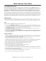
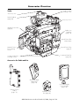
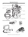
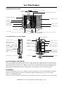
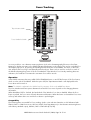
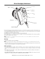
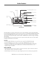
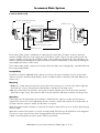
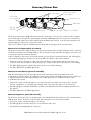
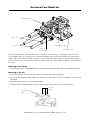
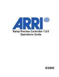
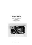
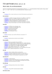
ARRICAM Accessories
Quick Guide
About, Software, Tools, Safety
3
Accessories Overview
4
Manual Control Box
6
Speed Control Box
7
Combined use of Manual & Speed Control Boxes
10
Timing Shift Box
12
Remote Control Station
13
Lens Data Box
14
Lens Data Displays
16
Focus Tracking
18
Wired Handgrip Attachment
19
Studio Readout
20
In-camera Slate System
21
Accessory Power Box
22
Universal Low Mode Set
23
ARRI Group Addresses
24
01/2004
This page is left blank intentionally.
ARRICAM Accessories Quick Guide 01/2004, Page 2 of 24
About, Software, Tools, Safety
About ARRICAM Quick Guides
This Quick Guide (order number K5.58313.0) provides a short introduction to the ARRICAM Accessories.
Further Quick Guides are dedicated to the ARRICAM Studio (K5.58311.0) and ARRICAM Lite (K5.58312.0).
An overview of all ARRICAM components, a cable overview and a Ground Glass overview, is given in the
ARRICAM System Guide (K5.58314.0). These guides do not replace the ARRICAM System User’s Guide
(K5.58508.0). It is essential that you acquaint yourself with the User’s Guide before operating the equipment.
These documents can be downloaded from www.arri.com in Acrobat pdf format. The Acrobat Reader can be
downloaded free from the Adobe web site at www.adobe.com. A PostScript printer gives best printing results.
Even though all efforts have been made to ensure this guide’s accuracy, changes and upgrades to the products
described can result in different hardware or behavior. Technical data are subject to change without notice.
Software version
This Quick Guide describes the ARRICAM System with Software Packet 03E. Different software versions can
result in different behaviours. Authorized ARRI Service Centers can check and update the ARRICAM software.
Tools
Anyone operating the ARRICAM system should have these tools:
1. One end of the ARRICAM Ground Glass Tool is used to remove the ground glass and the field lens. Use the
1.5 mm metric hex wrench at the other end to adjust the Integrated Video System and Frameglow alignment.
2. A 3 mm metric hex wrench is used to attach and remove most accessories.
3. A 5 mm metric hex wrench is used to attach or remove the Camera Handle grips, the 3/8” Accessory
Shoe Adapter and the WHA-2 Rosette Bracket.
4. A 8-10mm (5/16”) flathead long shaft screwdriver is used to attach baseplates, the Magazine Stabilization
Bracket and the ARRICAM Shoulder Set. Please note that screwdrivers with a short, stubby shaft will not
work with the Shoulder Set.
Safety specifications
• The Studio Viewfinder arm (hinge type) can be angled away from the camera to swivel it to the other side
of the camera. When this is done, make sure to securely hold the viewfinder arm, as it could otherwise
swing out rapidly and might cause pain and damage.
• Never place your hand in the lens port or inside of the camera while it is running.
• Assembly and initial operation should be carried out only by persons who are familiar with the equipment.
• Switch camera power off before making electrical connections (i.e. connecting accessory boxes).
• Never run the camera without a lens or a protective cap mounted in the lens port.
• Never operate the movement locking mechanism while the camera is running.
• Always ensure that the camera is securely mounted.
• Repairs should be carried out only by authorized ARRI Service Centers.
• Use only original ARRI replacement parts and accessories!
• In wet weather conditions the normal safety precautions for handling electrical equipment should be taken.
• Clean optical surfaces only with a lens brush or a clean lens cloth. In case of solid dirt moisten a lens cloth
with pure alcohol or a brand name lens cleaner.
• Do not use solvents to clean the film path, plexiglas parts or rubber seals.
• Do not remove any screws which are secured with paint.
ARRICAM Accessories Quick Guide 01/2004, Page 3 of 24
Accessories Overview
Studio
Studio Readout
mounting screw
Accessory shoe
Studio Readout
(page 20)
Accessory shoes
Manual Control Box
(page 6)
Studio Lens
Data Box
(page 14)
Speed Control Box
release button
Manual Control
Box mounting
screws
Speed Control Box
(page 7)
In-camera Slate Box
(page 21)
In-camera Slate Box
mounting screws
Accessories for Studio and Lite
Wired Handgrip
Attachment
(page 19)
Lens Data Display
for Focus Puller
(page 16)
Remote Control
Station
(page 13)
Manual Control
Box (page 6)
ARRICAM Accessories Quick Guide 01/2004, Page 4 of 24
Accessories Overview
Lite
Accessory shoes
Lite Camera Handle
Speed Control Box
(page 7)
Lite Lens Data Box
(page 14)
In-camera Slate
Box (page 21)
In-camera Slate Box
mounting screws
Lite Lens Data Box
mounting screw
Accessories for Studio and Lite
Accessory Power Box
(page 22)
Timing Shift Box
(page 12)
Lens Data Display
Classic (page 16)
ARRICAM Accessories Quick Guide 01/2004, Page 5 of 24
Universal Low
Mode Set
(page 23)
Manual Control Box
BRIGHT button
MANUAL CONTROL
FPS/ /OFF switch
FPS/SHUTTER display
MCB Cable Adapter
Handwheel
With the Manual Control Box (MCB), either the frame rate or the shutter angle can be manually adjusted. In
combination with the Speed Control Box (SCB), manual speed/shutter, speed/iris and shutter/iris ramps can
be performed – see the Combined use of the Speed & Manual Control Boxes section of this Quick Guide.
When the Speed and Manual Control Boxes are used together, the ramp time can be manually controlled.
mcu
Note: The MCB has to be removed prior to mounting or removing the SCB or Studio Camera Handle on the Studio.
Mounting
• On the Studio, remove the MCB port cover prior to mounting the MCB with two 3 mm hex screws.
• On both the Studio and the Lite a cable connection with the MCB is possible: Fix the MCB to either the MCB
Cable Adapter or the Remote Control Station with a 3 mm metric hex wrench. Both components can be linked
to the camera’s CAC connector with a cable: Either KC 65-S (3m/9ft) or KC 69-S (15m/45ft). These can be
extended a further 50m/165ft by using the Cable Drum.
Note: The MCB Cable Adapter can either be used with the MCB or the Timing Shift Box (TSB).
Note: When a Studio magazine is in back load position, it has to be removed for mounting or removing the MCB.
Compatibility
The MCB and the TSB can be used simultaneously to combine a ramp with a streaking effect. To do this, the
use of the MCB Cable Adapter, the Remote Control Station or the CAC Distribution Box is necessary.
Adjusting the frame rate
The FPS 1 position of the handwheel is the minimum (1 fps), the FPS 2 position is the maximum frame rate
(Studio: forward 60 fps, Lite: forward 40 fps, both: reverse 32 fps).
• Set the MANUAL CONTROL switch to FPS.
• Turn the handwheel to adjust the frame rate.
If the SCB is connected and its SPEED CONTROL switch is ON, the preset frame rates FPS 1 and FPS 2 of the
SCB determine the minimum and maximum fps of the MCB.
Note: The MCB speed setting has priority over the speed setting of both the Camera Control Panel and the SCB.
Adjusting the shutter opening
The handwheel MIN position is the minimum shutter opening (about 0°), the MAX
shutter opening (180°).
• Set the MANUAL CONTROL switch to
position is the maximum
.
• Turn the handwheel to adjust the shutter angle.
Note: If the SCB is connected to the camera, make sure its COMPENSATION switch is set to OFF.
Note: We don’t recommended shooting at shutter angles below 11.2° because correct exposure cannot be guaranteed.
Note: If a shutter/iris (depth of field/motion blur) ramp is set in combination with the SCB, the shutter opening
range of the MCB handwheel is restricted to MIN 11.2° and MAX 180°.
ARRICAM Accessories Quick Guide 01/2004, Page 6 of 24
Speed Control Box - Basic Camera Control
Basic
Camera
Control
(page 7)
Ramps
(page 8)
SPEED
CONTROL
Switch
External Synchronization (page 9)
Mounting
The Speed Control Box (SCB) attaches directly to the Studio. Press the release knob on the SCB port cover and
slide the cover towards the back of the camera to remove it. Position the SCB on the camera in place of the
cover, and slide forwards to lock it.
Note: If a Manual Control Box is attached to the camera, it must be removed to allow fitting of the SCB.
The SCB can also be linked by Cable KC 65-S (3m/9ft) or KC 69-S (15m/45ft) to the CAC connectors of the
Studio and Lite, either on its own, or in combination with other accessories if the Remote Control Station is
used. These cables can be extended a further 50m/165ft by using the Cable Drum.
Speed control
The SPEED CONTROL switch determines which functions are active.
ON
Fps 1 (with 0.001 fps accuracy), Fps 2 and the ramp time can be set and monitored. Forward and
reverse run can be set with the DIRECTION switch. The fps setting of the SCB has priority over the setting of the Camera Control Panel. Automatic speed/shutter and speed/iris ramps can be programmed
and executed.
SYNC The SCB can synchronize the camera’s frame rate to an external signal, e.g. video, another camera or projector.
OFF
The SCB controls neither speed nor shutter. Only the RUN, BRIGHT and iris OPEN/CLOSE buttons still work.
Setting frame rate and direction
Set the SPEED CONTROL switch to on. Enter the desired frame rate with the FPS 1 selector. Select FWD or REV
with the DIRECTION switch. If the Manual Control Box is connected to the camera, make sure its MANUAL
CONTROL switch is set to OFF or .
Note: Reverse run is not possible with Lite magazines.
ARRICAM Accessories Quick Guide 01/2004, Page 7 of 24
Speed Control Box - Ramps
Automatic versus manual speed ramps
An automatic speed ramp is a function where the start frame rate (FPS 1), duration of change (TIME) and end
frame rate (FPS 2) are preset. With the camera running, press the RAMP button to trigger the change from
FPS 1 to FPS 2, the duration of which is set by the TIME selectors. Press the RAMP button again at any time to
start the ramp back to FPS 1. Manual ramps can be performed by using the Speed Control Box together with
the Manual Control Box. During a manual ramp the camera speed or shutter angle is changed by with the
handwheel on the Manual Control Box.
Note: Holding the RAMP button depressed while the camera is in Standby will cause the FPS and SHUTTER
displays to alternately show the minimum ramp time (MinTime) achievable and screen time (ScrTime) of the
currently set automatic ramp. Screen time is calculated based on 24 fps playback speed.
Note: The Wireless Remote Control (WRC-1) can also be used to perform automatic or manual ramps.
Note: The MANUAL CONTROL switch on the MCB needs to be OFF for the automatic ramps described below to work.
Automatic speed/shutter ramps
When selecting shutter compensation, the camera will automatically pair the highest frame rate with a 180°
shutter angle, and calculate the required shutter angles to maintain constant film exposure.
• On the SCB set the SPEED CONTROL switch to ON.
• On the SCB set the COMPENSATION switch to SHUTTER.
• Enter the start frame rate with FPS 1, the duration with TIME and the ending frame rate with the FPS 2 selector switches.
• Once the RAMP LED is green, start the camera.
Note: If the FPS 1, TIME or FPS 2 LEDs flash red, the fps or time value set is too high or too low. If the COMPENSATION LED glows red, the fps range is too wide for the shutter range of 11.2° to 180°. Reduce the fps range.
Automatic speed/iris ramps with LDS lenses
To compensate a speed ramp with the iris, these additional components are required: a Lens Data Box (LDB),
an LDS Lens and a CLM motor. In performing a speed ramp with iris compensation, the iris is controlled by the
OPEN/CLOSE buttons on the SCB – if the Wireless Focus Unit is used, its iris control is overridden.
• On the SCB, set the SPEED CONTROL switch to ON.
• Set the COMPENSATION switch to IRIS. The CAL LED on the SCB will flash yellow if the motor is not yet calibrated.
• Press the CAL button on the SCB to calibrate the lens motor if necessary.
• Enter the start frame rate of the ramp with the FPS 1, the duration with the TIME and the end frame rate with
the FPS 2 selector switches.
• Use the OPEN and CLOSE buttons to set the start T-stop (the iris you want for FPS 1). The camera will
automatically calculate the required iris opening to maintain constant film exposure while ramping.
• Once the RAMP LED is green, start the camera.
Note: If the FPS 1, TIME or FPS 2 LEDs flash red, the fps or time value set is too high or too low. If the
COMPENSATION LED glows red, the iris cannot compensate for the preset fps range. Either try changing the
current iris with the OPEN and CLOSE buttons, or try reducing the fps range.
Automatic speed/iris ramps with non-LDS lenses
Speed/iris ramps with non-LDS lenses can be achieved by means of the ARRI Iris Control Unit (ICU) and an
ARRICAM ICU Cable (KC 72-S (1m/3ft); yellow to CAC, white to ICU) in combination with a CLM-1 motor. If
using a CLM-2 motor, the Lens Data Box is also necessary.
Note: The COMPENSATION switch on the SCB must be set to OFF.
Instead of the SCB, the Wireless Remote Control (WRC-1) can be used. A CLM-1 or CLM-2 motor has to be
connected to the Lens Data Box. The WRC needs software V1.08 or later.
ARRICAM Accessories Quick Guide 01/2004, Page 8 of 24
Speed Control Box - External Sync
Synchronisation of the camera to external sources
With the SPEED CONTROL switch set to SYNC, the SCB can synchronize the frame rate to an external source,
e.g. video signal, pulse generator or monitor. No sync function is possible when using a cable longer than 15
m/50 ft to connect the camera and SCB.
There are three different input signals that the SCB can accept.
1. A video signal can be fed into the VIDEO IN (BNC) connector.
2. The ARRI Pick-up Unit can be connected with the Cable KC 66-S (10m/33ft) to the SYNC IN (4 pin Fischer)
connector. The Pick-up Unit will sense the frequency of a CRT monitor when placed on or around it.
3. Any signal from 3 to 30 V with a frequency of 3 to 240 Hz can be input to the SYNC IN (4 pin Fischer)
connector. Pin 3 is SIGNAL, pin 4 SIGNAL GND.
Note: If a signal is present on the VIDEO IN and on the SYNC IN connector, the VIDEO IN connector has priority.
Note: In SYNC mode, the Speed Control Box will override the fps function of the Manual Control Box.
RATIO selector
The RATIO selector sets different ratios between input frequency and output fps. Use the table of examples
below to help choose the correct ratio for any given shot. Input frequencies can be from 3 - 240 Hz, keeping
in mind the top speed of the Studio (60fps) & Lite (40fps). For two seconds after the input frequency or RATIO
is changed, the FPS and SHUTTER displays show the input frequency and ratio respectively. If the input
frequency is present and valid, the FPS display will then show the output fps (indicated by an arrow). Otherwise it will show “Syn”.
Setting
0, 5 - 9
1
Ratio
1:1
2:1
2
3:1
3
4
4:1
5:2
Example Input Frequency (Hz)
24
48
50
59.94
60
70
72
75
100
59.94
Resulting Output fps
24
24
25
29.97
30
35
24
25
25
23.976
Notes
(e.g. projector)
(NTSC video signal)
(e.g. computer monitor)
(NTSC video signal)
Note: The shutter angle should be adjusted to 180° for all settings, except for the 5:2 ratio which should be 144°.
Other settings
• Usually, set the VIDEO IN 75 switch to ON when feeding a video sync signal into the VIDEO IN connector.
In case the video signal is forwarded (T connector) to a monitor, try ON or OFF to see which works better.
• If you feed a PILOT tone to the audio recorder, check with the sound department if they need 50 or 60 Hz.
• The PHASE setting determines the start of the exposure for each film frame in relation to when the image is
drawn on the video monitor. The result is the angled horizontal bar visible on the monitor seen through the
camera’s viewfinder. To prevent exposing the bar on film, the bar should not be visible through the viewfinder of the running camera. Try first the FIXED position of the PHASE (FIXED/MANUAL) selector; FIXED is
a phase value that works in most cases. If the horizontal bar is still visible, switch to MANUAL and use the
SYNC PHASE button to move the bar to where it is least visible. The camera remembers this phase setting
(the position of the bar) until the SYNC PHASE button is pressed again.
Note: The exception to this rule is when shooting with the RATIO selector in setting 0 or 5 - 9 (1:1). In this case the
worse the image in the viewfinder, the better it will be on film.
ARRICAM Accessories Quick Guide 01/2004, Page 9 of 24
Combined use of the Manual & Speed Control Boxes
The Speed Control Box on its own performs automatic speed/shutter or speed/iris ramps. When the Speed
Control Box is used together with the Manual Control Box, manually controlled speed ramps as well as shutter/
iris (depth of field/motion blur) ramps become possible.
The REMOTE LED on the Speed Control Box glows green when both these accessories work in combination.
When the MANUAL CONTROL switch on the Manual Control Box is set to SHUTTER (
functions on the Speed Control Box are overridden.
) or FPS, these
Note: For all the following ramp types the RAMP button and TIME selector on the Speed Control Box have no
effect, since the Manual Control Box controls the ramp.
Manual speed/shutter ramps.
• On the Manual Control Box set the MANUAL CONTROL switch to FPS.
• On the Speed Control Box set the SPEED CONTROL switch to ON.
• On the Speed Control Box set the COMPENSATION switch to SHUTTER.
• On the Speed Control Box enter the start and end frame rates of the ramp with the FPS 1 and FPS 2
selectors. These values define the limits of the MCB handwheel.
• Set the ramp’s starting fps with the Manual Control Box handwheel.
• Once the COMPENSATION LED is green, start the camera. Turn the Manual Control Box handwheel to
perform the ramp.
Note: The camera will automatically pair the highest frame rate with a 180° shutter angle, and calculate all other
shutter angles based on the resulting exposure time. If the FPS 1 or FPS 2 LED flash red, the fps value entered is too
high or too low. If the COMPENSATION LED glows red, the shutter cannot compensate for the fps range entered.
Try reducing the fps range.
Manual speed/iris ramps with LDS lenses
To compensate a speed ramp with the iris, these additional components are required: the Lens Data Box (LDB),
an LDS Lens and a CLM motor.
In performing a speed ramp with iris compensation, the iris can only be set with the OPEN/CLOSE buttons on
the SCB – the Wireless Focus Unit iris remote control is overridden.
• On the Manual Control Box set the MANUAL CONTROL switch to FPS.
• On the Speed Control Box set the SPEED CONTROL switch to ON and the COMPENSATION switch to IRIS.
• The CALIBRATION LED on the Speed Control Box now flashes yellow if the motor is not calibrated. In that
case, press the CAL button on the Speed Control Box to calibrate the iris motor.
• On the Speed Control Box enter the highest and lowest frame rates of the ramp with the FPS 1 and FPS 2
selectors. These values define the limits of the Manual Control Box handwheel.
• Use the Manual Control Box handwheel to find an fps setting that makes it easy to work out what T-stop
should be on the lens. e.g. 24fps; your normal shooting stop, 48fps; open by 1 stop over normal.
• At this handwheel setting, use the OPEN and CLOSE buttons on the Speed Control Box to set the T-stop.
• Set the ramp’s starting frame rate with the Manual Control Box handwheel.
• Once the COMPENSATION LED is green, start the camera. Turn the Manual Control Box handwheel to
perform the ramp.
Note: If the FPS 1 or FPS 2 LED flashes red, the fps value entered is too high or too low. If the COMPENSATION
LED glows red, the iris cannot compensate for the preset fps range. Try to change on the Speed Control Box either
the selected iris with the OPEN and CLOSE buttons or the fps range.
ARRICAM Accessories Quick Guide 01/2004, Page 10 of 24
Combined use of the Manual & Speed Control Boxes
Manual speed/iris ramps with non-LDS lenses
These can be done by means of the Iris Control Unit (ICU) and an ARRICAM ICU Cable (KC 72-S (1m/3ft);
yellow to CAC, white to ICU) in combination with a CLM-1 motor. If using a CLM-2 motor, a Lens Data Box is
also necessary.
• The COMPENSATION switch on the Speed Control Box has to be set to OFF.
The Wireless Remote Control (WRC-1), which needs software V1.08 or later installed, can be used instead of
the Manual Control Box control. A CLM-1 or CLM-2 motor has to be connected to the Lens Data Box.
Manual shutter/iris ramps with LDS lenses
During a shutter/iris ramp the frame rate stays constant. The shutter angle changes, and the lens’ iris
compensates to maintain a constant film exposure. The result is a change in the depth of field and in the
amount of motion blur. To do this the Lens Data Box, an LDS Lens and a CLM motor are needed.
In performing a shutter ramp with iris compensation, the iris can only be set with the OPEN/CLOSE buttons on
the Speed Control Box – the Wireless Focus Unit iris is overridden.
• On the Manual Control Box set the MANUAL CONTROL switch to
wheel is 11.2°, and the MAX
position is 180°.
. The MIN
position of the hand-
• On the Speed Control Box set the SPEED CONTROL switch to ON.
Note: Now the RAMP button and TIME selector on the Speed Control Box have no effect on the ramp, since the
Manual Control Box controls ramping.
• On the Speed Control Box set the COMPENSATION switch to IRIS.
• The CALIBRATION LED on the Speed Control Box now flashes yellow if the motor is not calibrated. In that
case, press the CAL button on the Speed Control Box to calibrate the iris motor.
• Set the ramp’s starting shutter angle with the Manual Control Box handwheel.
• Once the COMPENSATION LED is green, start the camera. Turn the Manual Control Box handwheel to
perform the ramp.
Note: If the COMPENSATION LED glows red, the selected iris position is too close to one of the limits of the iris
scale to be able to compensate for the shutter change. The mirror shutter can compensate for a range of 4 T-stops,
so in pairing e.g. T 4 with a 45° shutter angle, the shutter/iris ramp will be limited by T 2/11.2° and T 8/180°.
Change either the iris with the OPEN/CLOSE buttons on the Speed Control Box or the shutter opening with the
handwheel on the Manual Control Box.
Manual shutter/iris ramps with non-LDS lenses
A manual shutter/iris ramp with non-LDS lenses can only be achieved by means of the Wireless Remote
Control (WRC-1). A CLM-1 or CLM-2 motor has to be connected to the Lens Data Box. The Speed Control
Box is not necessary.
ARRICAM Accessories Quick Guide 01/2004, Page 11 of 24
Timing Shift Box
JITTER button
TIMING OFFSET
display
Timing
(+180/–180) scale
TIMING SHIFT
(ON/LOCK/OFF) switch
Handwheel
The Timing Shift Box (TSB) allows the creation of a streaking effect by adjusting the phase relationship of the
mirror shutter to the movement. The timing shift effect can be adjusted from very faint to very strong. The jitter
function introduces a random fluctuation in the effect, resulting in a fluctuation of the streak’s length.
Note: It is essential that you shoot film tests to get a feel for what settings produce the desired level of effect.
Like the Manual Control Box, the TSB can be attached directly to the Studio, to the Remote Control Station or connected via cable to the Studio and Lite – see Manual Control Box section of this Quick Guide.
Because the TSB is the same size and shape as the Manual Control Box, it has a red front panel to make it
easily distinguishable.
The TSB and the Manual Control Box can be used simultaneously to combine the streaking effect with a ramp.
Note: The camera noise may increase when using the Timing Shift Box, particularly with the jitter effect.
Controlling the timing shift effect
The white part of the Timing (+180/-180) scale is where the effect covers only parts of the image, the black
part is where the effect covers the whole image. The drop shaped labels indicate which way the streaks will go
(up or down), and in which edge the effect will start. On the display, (+) shows that the streaks will start on the
right edge and go up, while (–) shows that the streaks will start on the left edge and go down.
Controlling the jitter effect
Press the JITTER button to change the jitter level. A bar graph
to the left of the display shows the jitter level. With each press
of the button the Timing Shift Box will step through the four levels:
0 (none), 1 (low), 2 (medium) and 3 (high).
Timing shift
(in degrees)
Timing shift direction (+/–)
Performing a constant timing shift effect
• Set the TIMING SHIFT switch to ON.
JITTER level (1/2/3) bar graph
• Set the desired jitter level by pressing the JITTER button.
• Adjust the timing shift level by turning the handwheel.
• Set the TIMING SHIFT switch to LOCK. Now the current settings will be memorised and the handwheel as
well as the JITTER button has no control.
Performing a timing shift ramp
• Set the TIMING SHIFT switch to ON.
• Set the desired jitter level by pressing the JITTER button.
• A timing shift ramp is achieved by turning the handwheel while the camera is running.
ARRICAM Accessories Quick Guide 01/2004, Page 12 of 24
Remote Control Station
The Remote Control Station (RCS) allows the
use of the following accessories remotely:
MCB/TSB Holder
• Speed Control Box (SCB),
• Manual Control Box (MCB),
Accessory Shoe
• Timing Shift Box (TSB),
SCB
connector
• Wired Handgrip Attachment (WHA-2) with
Wireless Focus Unit (WFU-1) and
Wireless Zoom Unit (WZU-1) or
Wireless Remote Control (WRC-1),
SAC connector
WHA-2 connector
SCB
attachments
• Lens Data Display (LDD),
LDD connector
• Lens Data Display for Focus Puller (LDD-FP)
Mounting and connection
• Mount the SCB to the Remote Control Station by sliding it into place as when mounting it on the Studio camera.
• To fit the MCB/TSB Holder, undo the 3 mm hex screw and remove the cover at the top of the RCS. There is a
handy receptacle on the RCS for storing this cover when it is removed.
• Fix the MCB/TSB Holder on top of the RCS with one 3 mm hex screw.
• Mount the MCB or TSB on the MCB/TSB Holder with the two 3 mm hex screws.
The ARRI Dovetail System allows the RCS to be placed on the camera’s left side (with WHA-2 Rod or Rosette
Brackets) or to the Lite Camera Handle with the Dovetail 3/8” Clamp.
The Cables KC 65-S (3m/9ft) or KC 69-S (15m/45ft) allow the connection of the RCS (SAC connector) with
the camera (CAC connector). These can be extended a further 50m/165ft by using the Cable Drum. Make
sure you don’t connect to the SAC connector of the Speed Control Box by mistake.
Note: The SCB sync function will not work when using the Cable Drum KC 73-S (50 m/165 ft).
Studio or Lite (CAC connector)
MCB/TSB
Holder
MCB
OR
WZU-1 WFU-1
OR
TSB
WRC-1
SAC
WHA-2
WHA-2
LDD
SCB
RCS
OR
LDD-FP
ARRICAM Accessories Quick Guide 01/2004, Page 13 of 24
LDD
Lens Data Box
Lens Data System
The Lens Data System (LDS) allows the communication of LDS lens ring information to the camera. This information
can be displayed on one of the Lens Data Displays and on the Integrated Video System outputs. Besides the lens
information, the current depth of field and several camera settings will also be displayed.
LDS lens
An LDS lens is equipped with encoders that read lens
information which is communicated to the camera
via contacts on the lens mount. The lens ports of the
ARRICAM cameras and the ARRIFLEX 435 Advanced
have contacts in the 12:00 and 3:00 o’clock positions
so the lens data can be communicated to the other
LDS components. LDS lenses can be mounted on other,
non-LDS cameras just as non-LDS lenses with regular PL
mounts can also be used on the ARRICAM cameras.
LDS contacts
Lens Data Box
The Lens Data Box (LDB) controls lens motors, supplies the Lens Data Display with information and manages the
wireless or cabled connection to the Lens Control System (LCS). The Studio and Lite LDBs are physically
different to fit their respective camera bodies but have identical functions.
Lite Lens Data Box
Studio Lens Data Box
Antenna
Antenna
LDS READY LED
RF CHANNEL
selector
RF LED
Motor control LEDs
0
RF CHANNEL
selector
LDS READY LED
UNLOCK knob
RF LED
LCS
connectors
LCS connectors
Lens motor
direction switches
CLM-2 motor
connectors
CLM-2 motor
connectors
Motor control
LEDs
Lens motor
direction
switches
Mounting screw
ISB port cover
mounting screw
Mounting
• Studio: Press the release knob on the forward accessory port cover and slide the cover towards the front of
the camera to remove it. Replace the cover with the Studio Lens Data Box, which slides backwards until it fits
flush with the camera body.
• Lite: Use a 3mm metric hex wrench to remove the Lens Data Box cover. Replace the cover with the Lite Lens
Data Box and fasten it in place with the central mounting screw.
ARRICAM Accessories Quick Guide 01/2004, Page 14 of 24
Lens Data Box
Studio LDB Adapter
The Studio LDB Adapter enables the use of the Studio Lens Data
Box away from the Studio camera body, e.g. for use on the
Steadicam. Fit the Camera Plate on the camera body in place
of the LDB. Attach the LDB to the Adapter Plate and connect the
two plates with the LDB Adapter Cable; KC-75 (1m/3ft). The
Adapter Plate has three 3/8” threaded holes to assist mounting
by means of a support device like the ARRI Dovetail Shoe.
Adapter
Plate
Camera
Plate
Compatibility
The Studio Lens Data Box can only be connected to the ARRICAM Studio, just as the Lite Lens Data Box can
only be connected to the ARRICAM Lite. The Lite Lens Data Box is necessary to mount the In-camera Slate Box
(ISB) or the Accessory Power Box (APB) on the ARRICAM Lite.
All ARRI wireless hand control units and lens motors (CLM-1, CLM-2 and CFM-1) are compatible with the Lens
Data Box. The hand control units may be used with the Wired Handgrip Attachment (WHA-2) to connect to the LDB
with cables. The following hand control components can be attached to the WMU-1 and/or WHA-2: the Wireless Focus Unit (WFU-1), the Wireless Zoom Unit (WZU-1) and the Wireless Remote Control (WRC-1).
To connect a WHA-2, plug the Cable LC-M1-SP-S (1m/3ft) or LC-Z1-S (2m/6ft) either into the LDB (LCS connectors) or to a CLM-1 motor, if it is connected to the LDB. It is also possible to connect a second WHA-2 to the
camera. This however, must be into the CAC connector by means of a WHA-2 CAC Cable; KC 70 (3m/9ft)
and not into the LDB’s other LCS port.
Mount the WHA-2 to the Support Rods with the Rod Clamp, or to the ARRIHEAD with the Rosette Bracket.
Note: Components from the wired Lens Control System (LCS) like the Zoom Main Unit (ZMU-1), the Focus Iris Unit
(FIU-1) and the Iris Control Unit (ICU-1) can also be used with the LDB. When using the FIU-1, it is always recommended to not use a Wireless Main Unit or WHA-2 at the same time.
LDS READY LED
Off:
No LDS lens present.
Green:
LDS lens detected and all is working correctly.
Red:
LDS lens detected but there is a problem. Clean the contacts carefully or try another LDS lens.
Wireless operation
• Before switching on the camera, set the LDB’s RF CHANNEL selector to the desired channel. (See table below).
• Before switching on the Wireless Main Unit (WMU-1), set its RF CHANNEL selector to match that of the LDB.
The choice of RF channel should be made according to which channels are legal in your part of the world:
0, 1,
USA, Canada, Mexico, New Zealand, Europe except France and Spain
2
Europe except Spain
3
USA, Canada, Mexico, New Zealand, France
4
Japan
5, 6
Australia
7
Spain
8
Not assigned
Note: If the RF LED flashes red, there is another LDB (or UMC-1) nearby set to the same channel.
Note: If the RF LED glows red, the RF CHANNEL was altered while the radio was on. To remedy this, turn the RF
CHANNEL selector to 9 (RF off) and then to the Wireless Main Unit’s RF channel.
Note: When wireless operation is not needed, save power by setting the LDB’s RF CHANNEL selector to 9 (RF off).
ARRICAM Accessories Quick Guide 01/2004, Page 15 of 24
Lens Data Displays
Lens Data Display Classic (LDD)
Focus index line
Hyperfocal
distance line
Depth of field bar
Focal length/iris index line
POWER/SLEEP button
Camera info area
SET button
UP button
DOWN button
LDS info area
DELETE button
Message area
Focus mark
Focus scale
Iris scale
Zoom scale
POWER/SLEEP LED
Lens Data Display for Focus Puller (LDD-FP)
Depth of field bar
POWER/
SLEEP LED
ON/OFF switch
Unit of measurement
(M/LENS/FT) selector
LDD-FP connector
Camera info area
Hyperfocal
distance line
SET button
UP button
DOWN button
Actual focus/depth of
field (numerical) area
Focus/iris
index line
DELETE button
SCREEN/MENU
button
LDD-FP Holder
left side
Focus mark
Message area
Actual focal length/
actual iris area
Focus scale
Iris scale
front
Lens Data Displays (LDD, LDD-FP)
There are two different Lens Data Displays: The Lens Data Display Classic (LDD) and the Lens Data Display for
Focus Puller (LDD-FP). The LDD has a large TFT screen that shows all available information simultaneously. The
smaller LDD-FP shows the Lens Screen, with the Status Screen revealed by briefly pressing the MENU button.
Depressing the LDD-FP MENU button for longer (about 3 seconds), gives access to further sub-menus.
Compatibility
The Lens Data Displays work only in combination with a Lens Data Box or the Functional Expansion Module-2
(FEM-2) of the 435 Advanced. Both Lens Data Displays (LDD and LDD-FP) require one of the following to
connect to the ARRICAM system:
The LDD connector on either the Studio Readout, the Lite Mask Frameglow or the Remote Control Station (RCS).
ARRICAM Accessories Quick Guide 01/2004, Page 16 of 24
Lens Data Displays
Power/sleep function
• To turn on the LDD press the POWER/SLEEP button. To save power the LDD has a sleep mode.
If the lens barrels do not move, and the LDD buttons are not operated for about five minutes, the LDD goes to
sleep. The LDD screen can also manually be put to sleep by briefly pressing the POWER/SLEEP button again.
To wake it up, move any lens ring or briefly press the POWER/SLEEP button again.
• To power up the LDD-FP, set the ON/OFF switch to ON. If no information changes, the LDD-FP falls asleep
automatically after about two minutes. To wake it up, move any lens ring.
Note: The SLEEP status is indicated on both displays by a slowly blinking LED.
• To turn off the LDD, depress the POWER/SLEEP button for about 3 seconds.
• To turn off the LDD-FP, set the ON/OFF switch to OFF.
Start up
When either Lens Data Display is powered up and detects an LDS Lens, the lens barrels need to be turned so
that the system can recognize the lens ring markings. If lens motors are used, this will happen automatically
when the motors are calibrated. If lens motors are not used, this can be done by hand. Slowly turn the lens
barrels until the lens scales appear on the display.
Handling the focus marks
Setting
• Press the SET button to set a focus mark.
Deleting
• Move the focus ring until the focus mark lines up with the focus index line.
• Press the DELETE button.
• To delete all focus marks, hold the DELETE button depressed for 3 seconds.
Moving
•
•
•
•
Renumbering
• Move the focus ring until the focus mark lines up with the focus index line.
• Press the UP or DOWN buttons.
Turn the focus ring until the focus mark to move aligns with the focus index line.
Press the SET button until the mark disappears and keep it depressed.
Turn the lens focus ring.
Release the SET button.
Note: When renumbering one focus mark, the Lens Data Displays do not update the numbers on focus marks
already set, so beware that duplicate numbers are possible.
Hyperfocal distance
A small grey line in the focus scale shows the hyperfocal distance. When the lens is set to the hyperfocal
distance, everything from half the hyperfocal distance to infinity is in focus.
Circle of confusion
The circle of confusion (coc), used for the calculation of the depth of field and the hyperfocal distance, can be
selected on both Lens Data Displays. The default setting is 0.025 mm (1/1000”).
• On the LDD, DIP switches located under the rear coverplate of the LDD change the coc value.
• On the LDD-FP, the coc value can be changed with a sub-menu.
Unit of measurement
The Lens Data Display will automatically show the same unit of measurement (m or ft) as the LDS Lens. The unit
can be changed:
• On the LDD, by depressing either the UP button (m) or DOWN button (ft) while powering up.
• On the LDD-FP, by setting the UNIT selector either to M, LENS or FT.
ARRICAM Accessories Quick Guide 01/2004, Page 17 of 24
Focus Tracking
Tape Measure Mark
Focus Handwheel Mark
It is now possible to use a distance measuring device (such as the Cinematography Electronics Cine Tape
Measure) to display a pointer on the LDD-FP indicating the distance to the subject. This can be used simply for
information purposes or, by pressing and holding the FOCUS button on the WHA-3, the motor on the focus
axis will drive the focus ring to automatically track the subject. There is also a new line on the focus scale of
the LDD-FP indicating the position of the focus handwheel of the Wireless Focus Unit. By matching these two
indicators, the ‘handover’ from manual to automatic focus will be smooth.
Operation
In the LDD-FP main menu the entry called FOCUS TRACKING turns on and off the function of the focus button,
which is on the side of the WHA-3. With this option OFF, the Tape Measure Mark is still displayed but the
Focus Motor will not track it.
Note: The WHA-3 is identical to the WHA-2 with the exception of the newly added focus button.
The Slow, Medium and Fast options determine how fast the focus motor responds to the changing distance
information.
When Handwheel OFF is checked, the hand wheel of the Wireless Focus Unit is disabled. When the focus
button is pushed, the focus motor will track the measured distance. When the button is released the focus motor
will stop and remain where it is until the focus button is pushed again.
Compatibility
The following items are needed for focus tracking: Studio or Lite with Lens Data Box or 435 Advanced with
FEM-2, CLM-1 or CLM-2 lens motor, LDS lens, LDD-FP, Cine Tape Measure (or other distance measuring device
with industry standard output), WHA-3, CAC to CTM cable (0.7m/2ft).
ARRICAM Accessories Quick Guide 01/2004, Page 18 of 24
Wired Handgrip Attachment
RUN button
RELEASE
button
Lens calibration
(CAL) button
Lens calibration
LED
Dovetail Shoe
Wireless Focus
Unit (WFU-1)
WHA-2
connector
Wired Handgrip
Attachment (WHA-2)
The Wired Handgrip Attachment (WHA-2) allows the use of the following hand controllers of the Wireless Lens
Control System (WLCS) via cable connection: Either the Wireless Focus Unit and the Wireless Zoom Unit (singly
or combined), or the Wireless Remote Control.
The WHA-2 can also be connected to the FEM-2 of the 435 Advanced.
On the ARRICAM up to two WHA-2s may be connected; one via the Lens Data Box’s LCS connectors and the
other via the camera’s CAC connector.
Note: Although the Lens Data Box has two LCS connectors, the use of two WHA-2s connected to the LDB
simultaneously is not supported.
Mounting
• The hand controllers clip onto the WHA-2.
Note: The FOCUS knob of the WFU-3 is ergonomically better positioned for use on the WHA-2 than that of the WFU-1.
• The WHA-2 itself can be mounted with its Dovetail Shoe to several ARRI Dovetail parts like the Dovetail 3/8”
Clamp, the WHA-2 Rod Bracket or the WHA-2 Rosette Bracket.
Cable connections
• Use cable LC-M1-SP-S (1m/3ft) or LC-Z1-S (2m/6ft) to connect to either a Lens Data Box (LCS connector), the
Remote Control Station (WHA-2 connector) or to a CLM-1 motor which is already connected to the Lens Data
Box.
• Use cable KC 70-S (3m/9ft) to connect either to the Camera Accessory Connector (CAC) on the camera or
to the CAC Distribution Box.
• Use cable LC-M1-SP-S (1m/3ft) or LC-Z1-S (2m/6ft) to connect to either the FEM-2 (LCS connector) of a 435
Advanced or to a CLM-1 motor which is already connected to the FEM-2.
ARRICAM Accessories Quick Guide 01/2004, Page 19 of 24
Studio Readout
Lens Data Display (LDD) connector
RUN LED
FPS display
Accessory Shoe
BAT LED
Accessory
Shoe
BRIGHT button
RESET button
RAW STOCK button
SHUTTER display
EXPOSED FILM
display
camera left side
The Studio Readout can only be used mounted on top of a Studio Viewfinder or Studio Universal Viewfinder.
It has an FPS display and RUN LED on both sides. The left side also has SHUTTER and EXPOSED FILM displays.
The FPS and SHUTTER displays will either show the camera’s current values or, when necessary, messages
and warnings (see Studio Quick Guide, Lite Quick Guide or ARRICAM User’s Guide for listings of messages
and warnings).
The Studio Readout also has an LDD connector (other components with an LDD connector are the Lite Mask
Frameglow and the Remote Control Station).
Functions
• Pressing the RAW STOCK button shows the film reserve instead of the EXPOSED FILM length.
• Pressing the RESET button for more than 3 seconds resets the EXPOSED FILM counter to zero.
• Each press of the BRIGHT button steps through dim, medium and maximum brightness of all displays,
including the Lens Data Display Classic (LDD). This does not affect the LDD-FP, which has its own
brightness setting in a sub-menu.
RUN and BAT LEDs
• The RUN LED glows green when the camera is running at its preset fps. It glows red when the camera is
either running up or down or the camera is not ready.
• The BAT LED glows red when the power supply voltage drops below the low battery warning threshold.
ARRICAM Accessories Quick Guide 01/2004, Page 20 of 24
In-camera Slate System
In-Camera Slate Box (ISB)
Label
TC I/0 connector (for jamming)
TC LED
BATTERY Cover
SLATE EXPOSURE LED
TEST button
Mounting screws
In-camera Slate (ON/OFF) switch
Mounting screws
The In-camera Slate System is intended as a replacement for smart slates (TC slates). It exposes man and
machine readable characters in the image area on film before a take is exposed, at any camera speed. The
system is capable of exposing slate information (date, scene number, etc) and timecode. This information can
either be extracted automatically during telecine with the In-camera Slate Reader or afterwards by reading the
man-readable information off the screen.
The In-camera Slate System comprises the In-camera Slate Box (ISB), a Recording Module, a Handheld PC and
the In-camera Slate Reader.
Compatibility
The ISB fits on both the ARRICAM Studio and Lite. On the Lite, the Lite Lens Data Box must be present. Both
cameras accept the same Recording Module, which is installed inside the camera by authorised ARRI Service
Centers only.
Mounting
• Studio: Use a 3mm metric hex wrench to remove the lower accessory port cover from the camera right side
(fixed with two screws). Then place the ISB and fasten it with the two mounting screws.
• Lite: Use a 3mm metric hex wrench to remove the In-camera Slate Box port cover from the Lens Data Box
(fixed with a single screw). Then place the ISB on the Lens Data Box and fasten it with the mounting screws.
Operation
A head slate uses 20 empty frames and 18 frames of data when the camera is started, and 26 when it is
stopped. This will result in a noticeable delay when the camera is started and stopped. An end slate takes up
no frames when the camera is started, but 40 when it is stopped.
While the In-camera Slate information is exposed, the camera’s shutter will be set to 0°, and the shutter display
will show ISB0.
When the In-camera Slate System is used, the sensitivity (ASA) of the film must be entered into each magazine.
This ensures correct exposure even when changing between fast and slow filmstocks.
A label on the ISB explains the various states of the two status LEDs.
ARRICAM Accessories Quick Guide 01/2004, Page 21 of 24
Accessory Power Box
24 V dc outlets
24 V short circuit/
overload LED
Power input
connector (24 V)
Mounting screw
RUN button
BAT LED
RUN LED
Mounting screw
12 V dc outlets
12 V overload LED
The Accessory Power Box (APB) offers three extra 24 V dc and two 12 V dc power outlets as well as a RUN
button. Although it is designed to neatly integrate with either ARRICAM camera, it can also be used with any
camera to provide extra power outlets, albeit without the RUN button function. It can also be powered from a
separate battery to allow more current to be drawn.
There are a number of options available when mounting and powering the Accessory Power Box:
Mounted on and powered by the camera
The Accessory Power Box attaches directly onto the Studio instead of the In-camera Slate Box and so cannot be
used with it simultaneously. The APB attaches to the Lite only via the Lens Data Box and again, cannot be used
in conjunction with the In-camera Slate Box.
In this configuration, the Accessory Power Box draws its power from the camera electronics and, although this
is the neatest arrangement, the amount of power the APB can deliver in this mode is limited.
• Total power output is 70 watts. e.g. The 24 V outlets can deliver 3 amps between them in total. If the 12 V
outlets are used, they can deliver 3 amps, leaving only 1.5 amps for the 24 V outlets. (Power = Volts x Amps)
• The APB’s BAT light glows red when the camera shows its low battery warning.
• The APB’s RUN button and RUN light function.
Mounted on the camera, powered externally
With this method the Accessory Power Box mounts in the same way as the first example and so has
communication with the camera. The difference is that power is fed into the APB’s power connector either from
a separate battery of from the camera battery via a Y-cable (KC-62-S). This enables the APB to output
considerably more power.
• Total power output is 250 watts approx. e.g. Each 24 V outlet can supply 3 A continuously, 5 A peak.
(24 V is unregulated, so is actually supply voltage). Each 12 V outlet can supply 1.5 A continuously.
• The BAT light glows red when the battery connected to the APB falls below the Low Battery threshold set in
the camera.
• The APB’s RUN button and RUN light function.
Mounted anywhere, powered externally
The Accessory Power Box Cover is equipped with a 3/8 threaded hole which allows it to be mounted with the
ARRI Dovetail system. Therefore it can be placed almost anywhere on or around any camera.
• Total power output is 250 watts approx. (see above).
• The BAT light glows red when the power source falls below 20.5 volts.
• The RUN button and RUN light do not function.
ARRICAM Accessories Quick Guide 01/2004, Page 22 of 24
Universal Low Mode Set
Steadicam Plate
19mm rods
15mm rods
Lite Mounting Plate
Support
Rod Holder
Left Support Arm
The Universal Low Mode Set allows the Studio or the Lite to be underslung on a Steadicam. The set consists
of a Steadicam Plate, two Support Arms, a Lite Mounting Plate and a Support Rod Holder. The Support Rod
Holder slides into a dovetail located on the front of both 100% Video Tops and has to be fixed by a single 3
mm hex screw in the correct position on both the Studio and the Lite. The Lite Mounting Plate is not required for
the Studio.
Mounting on the Studio
• Fix both Support Arms to the threaded holes on the left and right side of the Studio with a 3 mm metric hex wrench.
Mounting on the Lite
• With the Viewfinder removed from the camera, first attach the Lite Mounting Plate.
• Now fit the Lite Integrated Video System onto either a Lite 100% Video Top, Lite Viewfinder or Lite Universal
Viewfinder.
• Attach the Support Arms to the Lite Mounting Plate.
• Finally, attach the Steadicam Plate to the top of the Support Arms with the four 3 mm hex screws .
Lite Mounting
Plate
mounting
screws
ARRICAM Accessories Quick Guide 01/2004, Page 23 of 24
ARRI Group Addresses
Canada
ARRI Canada Limited (Sales & Service)
415 Horner Ave. Unit 11, Toronto, Ontario M8W 4W3, Canada
Voice phone: +416 255 3335, FAX: +416 255 3399
Email: [email protected]
Germany
Arnold & Richter Cine Technik (Headquarters, Sales & Service)
Türkenstraße 89, D-80799 Munich, Germany
Voice phone: +49 (0)89 3809-0, FAX: +49 (0)89 3809-1244
Email: [email protected]
ARRI Camera Rental (Film Equipment Rental)
Türkenstraße 89, D-80799 Munich, Germany
Voice phone: +49 (0)89 3809-1240, FAX: +49 (0)89 3809-1798
Email: [email protected]
Great Britain
ARRI GB Limited (Sales & Service)
2 Highbridge, Oxford Road, Uxbridge, Middlesex, UB8 1LX, England
Voice phone: +44 (0)1895 457 000, FAX: +44 (0)1895 457 001
Email: [email protected]
ARRI MEDIA (Camera Rental)
3 Highbridge, Oxford Road, Uxbridge, Middlesex, UB8 1LX, England
Voice phone: +44 (0)1895 457 100, FAX: +44 (0)1895 457 101
Email: [email protected]
ARRI Lighting Rental (Lighting Rental)
4 Highbridge, Oxford Road, Uxbridge, Middlesex, UB8 1LX, England
Voice phone: +44 (0)1895 457 200, FAX: +44 (0)1895 457 201
Email: [email protected]
Italy
ARRI Italia S.r.l. (Sales & Service, Milan)
Viale Edison 318, 20099 Sesto San Giovanni (Milan), Italy
Voice phone: +39 (0)2 262 271 75, FAX: +39 (0)2 242 1692
Email: [email protected]
ARRI Italia S.r.l. (Sales & Service, Rome)
Via Placanica 95, 00040 Morena (Rome), Italy
Voice phone: +39 (0)6 726 707 97, FAX: +39 (0)6 723 1541
E-mail: [email protected]
USA
ARRI Inc. (Sales & Service, East Coast)
617 Route 303, Blauvelt, NY 10913-1123, USA
Voice phone: +1 914 353 1400, FAX: +1 914 425 1250
Email: [email protected]
ARRI Inc. (Sales & Service, West Coast)
600 North Victory Blvd., Burbank, CA 91502-1639, USA
Voice phone: +1 818 841 7070, FAX: +1 818 848 4028
Email: [email protected]
CSC Camera Service Center (Film Equipment Rental, NY)
619 West 54th St, New York, NY 10019, USA
Voice phone: +1 212 757 0906, FAX: +1 212 713 0075
Email: [email protected]
World Wide Web
CSC Camera Service Center (Film Equipment Rental, Florida)
2385 Stirling Road, Fort Lauderdale, FL 33312, USA
Voice phone: +1 954 322 4545, FAX: +1 954 322 4188
Email: [email protected]
www.arri.com
ARRICAM Accessories Quick Guide 01/2004, Page 24 of 24