1
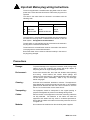
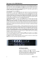
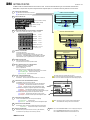
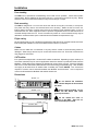
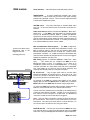
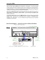
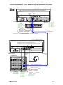
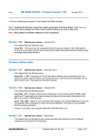
ALLEN&HEATH
iDR0
iLive Mix System DSP MiniRack
USER GUIDE
Publication AP7129
Limited Two Year Warranty
This product has been manufactured in the UK by ALLEN & HEATH and
is warranted to be free from defects in materials or workmanship for a
period of two years from the date of purchase by the original owner.
To ensure a high level of performance and reliability for which this
equipment has been designed and manufactured, read this User Guide
before operating.
In the event of a failure, notify and return the defective unit to ALLEN &
HEATH or its authorised agent as soon as possible for repair under
warranty subject to the following conditions:
Conditions Of Warranty
1. The equipment has been installed and operated in accordance with
the instructions in this User Guide
2. The equipment has not been subject to misuse either intended or
accidental, neglect, or alteration other than as described in the User
Guide or Service Manual, or approved by ALLEN & HEATH.
3. Any necessary adjustment, alteration or repair has been carried out
by ALLEN & HEATH or its authorised agent.
4. The defective unit is to be returned carriage prepaid to ALLEN &
HEATH or its authorised agent with proof of purchase.
5. Units returned should be packed to avoid transit damage.
In certain territories the terms may vary. Check with your ALLEN &
HEATH agent for any additional warranty, which may apply.
This product complies with the European Electromagnetic
Compatibility directives 89/336/EEC & 92/31/EEC and the
European Low Voltage Directives 73/23/EEC & 93/68/EEC.
Any changes or modifications to the power supply unit not approved
by Allen & Heath could void the compliance of the product and
therefore the users authority to operate it.
iDR0 User Guide AP7129 Issue 1.
Copyright © 2008 Allen & Heath. All rights reserved
Manufactured in the United Kingdom by Allen & Heath Limited
Kernick Industrial Estate, Penryn, Cornwall, TR10 9LU, UK
http://www.allen-heath.com
2
iDR0 User Guide
Important Safety Instructions
WARNINGS
- Read the following before proceeding :
CAUTION
ATTENTION: RISQUE DE CHOC ELECTRIQUE – NE PAS OUVRIR
Read instructions:
Retain these safety and operating instructions for future reference. Adhere to
all warnings printed here and on the equipment. Follow the operating
instructions printed in this User Guide.
Do not remove covers:
Operate the equipment with its covers correctly fitted. Refer any service work
on the equipment to competent technical personnel only.
Power sources:
Connect the equipment to a mains power supply only of the type described
in this User Guide and marked on the rear panel. Use only the power cord
with sealed mains plug appropriate for your local mains supply as provided
with the equipment. If the provided plug does not fit into your outlet consult
your service agent for assistance.
Power cord routing:
Route the power cord so that it is not likely to be walked on, stretched or
pinched by items placed upon or against it.
Grounding:
Do not defeat the grounding and polarisation means of the power cord plug.
Do not remove or tamper with the ground connection in the power cord.
WARNING: This equipment must be earthed.
Water and moisture:
To reduce the risk of fire or electric shock do not expose the equipment to
rain or moisture or use it in damp or wet conditions. Do not place containers
of liquid on it which might spill into any openings.
Ventilation:
Do not obstruct the ventilation slots or position the equipment where the air
flow required for ventilation is impeded. If the equipment is to be operated in
a flightcase ensure that it is constructed to allow adequate ventilation.
Heat and vibration:
Do not locate the equipment in a place subject to excessive heat or direct
sunlight as this could be a fire hazard. Locate the equipment away from any
devices which produce heat or cause excessive vibration.
Servicing:
Switch off the equipment and unplug the power cord immediately if it is
exposed to moisture, spilled liquid, objects fallen into the openings, the
power cord or plug become damaged, during lightening storms, or if smoke,
odour or noise is noticed. Refer servicing to qualified technical personnel
only.
Installation:
Install the equipment in accordance with the instructions printed in this User
Guide. Use the equipment connections for their intended purpose only.
iDR0 User Guide
3
Important Mains plug wiring instructions.
The unit is supplied with a moulded mains plug fitted to the AC mains
power lead. Follow the instructions below if the mains plug has to be
replaced.
The wires in the mains lead are coloured in accordance with the
following code:
WIRE COLOUR
TERMINAL
European
USA/Canada
L
LIVE
BROWN
BLACK
N
NEUTRAL
BLUE
WHITE
E
EARTH GND
GREEN & YELLOW
GREEN
The wire which is coloured Green and Yellow must be connected to
the terminal in the plug which is marked with the letter E or with the
Earth symbol. This appliance must be earthed.
The wire which is coloured Blue must be connected to the terminal in
the plug which is marked with the letter N.
The wire which is coloured Brown must be connected to the terminal
in the plug which is marked with the letter L.
Ensure that these colour codes are followed carefully in the event of
the plug being changed.
Precautions
4
Damage :
To prevent damage to the equipment cosmetics, avoid placing heavy
objects on the unit, scratching the surface with sharp objects, or
subjecting the unit to rough handling and vibration.
Environment :
Protect from excessive dirt, dust, heat and vibration when operating
and storing. Avoid tobacco ash, smoke, drinks spillage, and
exposure to rain and moisture. If the equipment becomes wet, switch
off and remove power immediately. Allow to dry out thoroughly
before using again.
Cleaning :
Avoid the use of chemicals, abrasives or solvents. The equipment is
best cleaned with a soft brush and dry lint-free cloth. If the ventilation
grilles become blocked with dust use a vacuum cleaner to suck the
dirt out. Do not remove the cover to clean the unit.
Transporting :
The equipment should be transported in the original packing or
purpose built flightcase to protect it from damage during transit.
Cables:
Plan the location of the equipment so that the connecting cables are
not fully extended. Full extension of the cables can stress the
equipment and cables and may result in undesired performance.
Ensure that the cables are located such that they cannot be stood on
or tripped over.
Modules:
Do not remove the modules from the unit while power is applied.
iDR0 User Guide
Introduction
This is the user guide for the Allen & Heath iDR0 ‘MiniRack’ mix engine. We recommend
that you read this fully before starting. Included is information on installing, connecting
and operating the unit along with panel drawings, application drawings and technical
specification. Whilst we believe the information in this guide to be reliable we do not
assume responsibility for inaccuracies. We also reserve the right to make changes in the
interest of further product development.
We are able to offer further product support through our worldwide network of approved
dealers and service agents. You can also access our Web site (www.allen-heath.com)
for information on our company and its pedigree, our full product range and our design
philosophy. To help us provide the most efficient service please keep a record of your
unit serial number, and date and place of purchase to be quoted in any communication
regarding this product. The serial number is located on the rear panel.
The iDR0 is one of many components that can connect together to create an iLive
mixing system. For further information on configuring and using iLive please refer to:
iLive System Reference guide
AP6526
iDR0 Getting Started Guide
AP7284
iLive Getting Started Guide
AP7260
Allen & Heath Resource CD
AP4742
Allen & Heath web site
www.allen-heath.com
Firmware Release Notes
Downloadable from web site
Help file within system firmware
Check the packing contents
Retain the product packing should you need to ship the product in future. You should find the
following components:
1x iDR0 MiniRack. This is packed with its rubber feet
fitted. The feet can be removed for rack mounting.
1x IEC MAINS LEAD with moulded plug. Check that the
plug is suitable for connection to your local mains
supply.
iDR0/n
Where n = mains voltage 120 (USA), 220 (EU), 240 (UK)
1x CAT5 CABLE 1.8m RJ45 Ethercon connections.
Part number AH7001. Connects the iDR0 to the iLive
Surface or another MixRack. Note that the second cable
required is shipped with the iLive Surface.
DOCUMENTATION including the User Guide AP7129,
Getting Started Guide AP7284, Safety Sheet AP3345,
Registration Card AP3594, and sticker AP4943.
iDR0 User Guide
5
Welcome to the iDR0 MiniRack
The iDR0 is a compact, rack mountable unit housing the ‘brains’ of the iLive digital mixing system. It
features a 64 input x 32 bus architecture with full channel and mix processing together with 8 internal
effects processors. Unlike the bigger iDR10 unit, the iDR0 has no provision for fitting audio input and
output cards. Instead, it gets its audio via the EtherSound digital audio network. This provides a
compact solution for split FOH/monitor/recording applications or for stand alone systems where all
the audio is available at the rear of the iLive Surface.
The two main applications for the iDR0 are:
Split FOH/Monitor - Two iLive systems are linked using a single set of microphone preamps loaded
into one rack. One system uses an iDR10 which has 10 slots for loading the input and output
modules including the mic preamps. The second system uses the smaller iDR0 which has no audio
slots and gets its channel sources from the first via an EtherSound ‘digital splitter’. This can be more
convenient, space saving and cost effective than loading two sets of preamps and using a bulky
analogue splitter. One engineer has control over the preamp gains affecting both systems, while the
second engineer has digital channel trims to make additional adjustments.
Compact stand alone mixer - The more compact iDR0 MiniRack can be used in place of the larger
iDR10 MixRack to create a high quality small format mixer with all its audio inputs and outputs
available on the rear of the Surface. Four card slots allow up to four input or output modules to be
fitted providing a total of 32 sockets. For example, a typical format may be 24 inputs and 8 outputs.
If you take into account the 8 internal stereo effects processors this provides the equivalent of an
analogue console with 24 mono inputs plus 8 stereo inputs (returns) and 16 outputs (including the
effects sends). In addition, further inputs and outputs may be connected via other EtherSound input
and output devices.
The 2U case houses three plug-in modules – the iDR-64 ‘Rack-Extra’ DSP mix engine, CPU control
module with network, MIDI and PL-Anet interfaces, and RAB remote audio interface module with two
EtherSound network cards fitted as standard, digital clock, and a headphones output at the rack.
The ESA network transports audio to and from the Surface rear panel card options, while ESB
provides a 64 channel digital snake to connect to another MixRack or EtherSound recording device.
The user can map selected signals to and from the 64 channel EtherSound audio network. The DSP
processes 64 input channels, 32 mix outputs and up to 8 internal effects, with full processing
available at all times on all inputs and outputs.
Two CAT5 connecting cables are required between the iDR0 and iLive Surface, one for Ethernet
control, the other for EtherSound audio. One CAT5 cable is all that is needed to connect between
two racks to link the audio between iLive systems.
The iDR0 has an internal, universal voltage mains supply, and allows connection to the Allen & Heath
iPS10 rack mount psu if redundant supply backup is required.
GETTING STARTED…
A single sheet Getting Started guide (publication
AP7284) is available for the iDR0.
For your
convenience it is reprinted here. Whilst it does give
you a very quick way to start configuring and using
iLive we do recommend that you read through the rest
of this guide to learn more about the system first.
6
iDR0 User Guide
iDR0
GETTING STARTED
AP7284 iss.1 V1.2
The iDR0 is similar to the iDR10 but without the slots for audio I/O cards. It is the iLive 'brain' with DSP mix engine, control and audio network interfaces.
iDR0 provides a compact solution for systems using EtherSound as a digital mic splitter, or as a stand alone mixer using audio at the rear of the surface.
1 CHOOSE YOUR APPLICATION
[A] COMPACT STAND ALONE MIXER
[A] Stand alone mixer with audio at rear of surface
[B] Split FOH/Monitor dual console system
2 CHOOSE SURFACE SIZE
Audio on rear of surface
iLive-176 44 faders, 176 strips
iLive-144 36 faders, 144 strips
Network control
iLive-112 28 faders, 112 strips
ES audio
iDR0
iLive-80 20 faders, 80 strips
Analogue multicore
Mix engine
3 CHOOSE AUDIO MODULES FOR LOCAL AUDIO AT THE SURFACE
[B] SPLIT FOH / MONITOR SYSTEM
Load up to 4x 8 channel audio modules, eg - 24 inputs + 8 outputs
BLANK
M-BLANK-A
MIC/LINE
M-MICIN-A
DUAL MIC
M-DUALIN-A
DIGITAL IN
M-DIGIN-A
LINE OUT
M-LINEOUT-A
DIGITAL OUT
M-DIGOUT-A
SLAVE system
Network control
ESA local audio
iDR0
Mix engine
MULTI OUT
M-MULTI-OUT-A
16 outputs, takes up 2 slots
4 CONNECT UP THE SYSTEM
Connect mains power leads
Connect backup iPS10 power supplies if required
Audio network - Plug iDR0 ESA OUT to Surface ESA IN (1x CAT5 cable)
Control network - Plug iDR0 NETWORK to Surface NETWORK (1x CAT5 cable)
If split FOH/Monitror system - Plug iDR0 ESB IN from master iDR10 ESB out
MASTER system
Network control
5 POWER UP THE SYSTEM
ESA local audio
Switch on the MixRack and Surface
The system should connect and boot up within 2 minutes
ALLEN&HEATH
6 LOAD A TEMPLATE SHOW AS A STARTING POINT
iDR-64
Press UTILITY / Configuration / Show Manager
Select TEMPLATES from the left window
Press + to expand the list
Select and Recall a show as a starting point for using your system
ESB mic splitter
MIX ENGINE
[A] iDR0_LR_24in8out Stand alone mixer with audio I/O at rear of surface
[B] SLAVE_MON_8m8st Monitor console slave system
[B] SLAVE_FOH_LR FOH console slave system
7 RECALL SCENE FOR SURFACE SIZE
If the Surface audio does not appear where you expect it:
eg. If it has been changed using an external application such as ES Monitor
You can resore the EtherSound configuration to standard mapping using this:
Gives you a logical layout for your Surface size
Press SCENES - Select and recall scene STRIPnnn where nnn = surface size
8 CHECK AUDIO CLOCK AND ETHERSOUND SETTINGS
Audio Sync/Networks
Press MIXRACK / Mixer Pref / Audio Sync Networks
Check Audio Clock setting (Chooses the source to syncronise the digital audio)
Audio Clock Source
[A] INTERNAL Stand alone mixer with audio I/O at rear of surface
[B] ESB Slave FOH or Monitor system with ESB digital mic splitter
Check EtherSound configuration (Configures the digital audio network mapping)
Stand alone mixer with audio I/O at rear of surface
[A] MASTER
[B] MASTER/SLAVE Slave FOH or Monitor system with ESB digital mic splitter
Check Channel Source settings (Chooses which inputs feed the channels)
Quick Input Setup
Global ESB Input
SET
Global Local Input
SET
Restore ESA Defaults
SET
ESB Config
Master
Slave
SET
SET
[A] Local Inputs Stand alone mixer with audio I/O at rear of surface
[B] ESB Inputs Slave FOH or Monitor system with ESB digital mic splitter
9 CHECK INPUT SOCKET MAPPING
From IP channel PREAMP screen check for required socket patching
Stand alone mixer
[A] Surface Slot A-D
[B] ESB ch 1-64 Slave FOH or Monitor system with ESB digital mic splitter
NOTE: The Audio Clock Source is stored in Scene and Show memories
The ESB Master/Slave setting are not stored in the memories
10 CHECK OUTPUT SOCKET MAPPING
Press OUTPUTS / Surface to check which signals feed the Surface output sockets
Surface Slot A-D
11 ARCHIVE YOUR SETTINGS
Stand alone mixer outputs or local slave outputs
Name and archive your setup as a Show for each iLive (eg. FOH and Monitor)
You could also store your settings as a Scene memory (Select All)
iDR0 User Guide
12 MORE... Refer to the iLive REFERENCE GUIDE for more on configuring and using iLive
Refer to the FIRMWARE RELEASE NOTES for more on new features
Refer to WWW.ALLEN-HEATH.COM for the latest information on iLive
7
Installation
Free standing
The iDR0 can be operated as a freestanding unit for shelf or floor operation. Check that its plastic
feet are fitted. Ensure adequate air flow around the unit. It must not be covered in any way. Always
stand the unit on a firm flat surface away from any soft furnishings or carpet.
Rack mounting
The iDR0 is designed as a 19 inch rack mount unit and will occupy 2U (3.5 inches) of rack space.
The plastic feet may need to be removed before rack mounting. Retain the feet for future use.
Ensure natural convection of airflow around the unit by allowing good ventilation below, in front of
and behind the unit. Rack equipment known to produce a significant amount of heat should not be
mounted directly below the unit. Forced convection by means of a rack mounted fan-tray may be
desirable in situations where space is restricted and the ambient air temperature is high.
Flight casing
We recommend that you use a professional grade flight case with shock mounted internal rack frame.
Ensure adequate ventilation in front of and behind the unit when it is powered.
Cables
Make sure the cables are not stretched in any way and are routed to avoid becoming kinked or
damaged. Allow enough service loop for access and removal of the unit. Ensure all connectors are
fully plugged in and locked.
CAT5 cables
iLive systems are shipped with 1.8 metre CAT5 cables as standard. Depending on type, cables up to
100 metres (330 feet) may be used for applications where the Surface is positioned remote from the
MiniRack. Cable approved by Digigram for EtherSound use should be sourced. Check the Digigram
web site for further information (www.ethersound.com/technology/compatibility.php). Allen & Heath
can supply an 80 meter drum of suitable cable if needed, part number AH7000. Two of these are
required to connect control and audio between the MiniRack and the Surface. One is required to
connect audio between the MiniRack and another remote rack.
88 mm / 3.46"
Dimensions
483 mm / 19"
Do not obstruct the ventilation
slots. Ensure adequate air flow around
the iPS10.
443 mm / 17.4"
Ensure proper grounding. Do not
remove the IEC mains cord earth
(ground) connection.
2U
374 mm / 14.7"
310 mm / 12.2"
8
Do not remove the cover or
modules of the iDR0. There are no
user serviceable parts inside.
iDR0 User Guide
Front panel controls, connections and operation
CPU (Control) module
TO AVOID DAMAGE ONLY CONNECT
COMPATIBLE REMOTE CONTROL
EQUIPMENT TO THE PL-Anet PORT.
CAUTION 20V DC
PL-Anet
OUT
THRU
IN
MIDI
iDR-64
OUT
IN
DARS
SYNC
TX
RX
ESB
TX
RX
TX
RX
ALLEN&HEATH
M-RAB-D
OUT
IN
IN
ESA
TX
RX
SYSTEM LOCK
10
0
OUT
MINI RACK
PAFL
(CHK)
BACKUP PSU
INTERNAL PSU
ON
ON
iDR RACK
REMOTE AUDIO
DSP
RackExtra
iDR0
ON
iDR0 RACK
CPU
Allows control of the system using an iLive Surface, PC or other devices.
MIX ENGINE
M-ETH-M
RAB (Remote Audio) module
Audio network card options
iDR-64 RackExtra DSP module
Connects audio to and from the rack
using a single cable digital format for
each of two independent audio
networks.
Up to two cards may be fitted.
The ES (EtherSound) card
handles 64 channels of bidirectional audio.
The audio ‘mix engine’ which
digitally processes up to 64 input
channels, 32 mix outputs and 8
internal effects.
CPU module
Power indicators - Blue LEDs light to indicate power present.
NETWORK - A 3 port Ethernet switcher is built in. This lets you
connect several network devices to the iDR0, for example an iLive
Surface and a laptop running the iLive System Manager software.
While searching for the connection after device power up, the
LINK/ACT indicator flashes at a slow rate. This may take a few
seconds. Once the connection is successfully made the indicator
flashes at a steady fast rate.
Note: Do not connect more than one network cable between two
devices. Attempting to connect a second cable as a ‘redundant
backup’ will result in loss of control.
Note: When using firmware versions up to V1.2, disconnection of the
network cable or loss of network connection requires a Surface
reboot.
Default MiniRack settings are:
IP address 192.168.1.1
Subnet mask 255.255.255.0
Gateway 192.168.1.254
Reset Settings - A recessed switch lets you reset the network
address and settings to factory default. This is useful if you are using
a MiniRack and a Surface with unknown network addresses or which
had different addresses previously set. Resetting each networked
device (MiniRack, Surface and TouchScreen) will ensure the devices
connect correctly. To reset the settings, press and hold the switch in
using a pointed object while powering up the rack. Keep the switch
pressed for at least 10 seconds while the rack boots.
MIDI IN, THRU and OUT - Standard MIDI interface for external
system control using MIDI messages. For more information refer to
the iLive Reference Guide and firmware version release notes.
PL-Anet - Proprietary RS485 based control port for connecting
Allen & Heath PL Series remote controllers such as wall plates, GPIO
and fader/encoder panels. For more information refer to the iLive
Reference Guide, PL Series guides and firmware release notes.
iDR0 User Guide
9
RAB module
Power indicator - A blue LED lights to indicate power present.
HEADPHONES - A built-in headphones amplifier with volume
control and ¼” output socket lets you listen to the signal currently
selected using the PAFL function. This is the same signal presented
to the Surface headphones system.
SYSTEM LOCK - The yellow LED lights to indicate digital audio
sync lock. If it is not lit check that the correct Audio Clock Source is
selected.
Audio Clock Source (Surface TouchScreen MIXRACK / Mixer Pref /
Audio Sync) - If the iDR0 is the slave getting its channel preamp
sources via EtherSound network ESB in a linked FOH/Monitor
system then the Clock Source should be set to ‘ESB’. If it is being
used as a stand alone system getting its audio from the Surface via
ESA only then it should be set to ‘Internal’. If it is being synchronized
to an external DARS source then set it to ‘DARS’.
To learn more about using
EtherSound refer to the
Digigram web site:
www.digigram.com/
SURFACE
NETWORK
ESB Config (Surface TouchScreen MIXRACK / Mixer Pref / Audio
Sync) - This screen lets you configure the iDR0 to be the
EtherSound master or slave. For example, if it is a slave in an
FOH/Monitor system then set it to MASTER/SLAVE. If it is being
used with a Surface as a stand alone mixer then set it to MASTER.
This config setting is not stored in the iLive Show memories and
should be set manually when you configure the system.
ES IN and OUT - Plug a single CAT5 cable to connect audio
between the MiniRack and another device. Plug OUT to IN. Plug
into the OUT socket on whichever device is the audio clock master.
Plug into the IN socket on the slave device.
ESA IN
ESA OUT
iDR0
ESB IN
ESA and ESB audio network options - The iDR0 is shipped as
standard with both card slots fitted with the EtherSound option. Use
ESA to transport audio to and from the iLive Surface and/or other
EtherSound equipped devices such as break out / break in boxes
and speaker controllers. Us e ESB to transport audio between iDR
racks and other EtherSound equipped devices such as the Digigram
LX6464 PCI multitrack recording card.
For example, if the iDR0 is a monitor slave getting its mic signals
digitally split from the FOH iDR10 master via ESB, then connect the
iDR10 ESB OUT to the iDR0 ESB IN sockets using a single cable.
To connect the iDR0 to the Surface audio modules, headphones and
talkback, connect its ESA OUT to the Surface ESA IN socket.
Correct connection of EtherSound is indicated by the steady flashing
of both the yellow RX and TX LEDs. If neither or just one is flashing
then check for correct connection or a cable fault. The EtherSound
connection is made as soon as the cable is plugged in.
iDR10
ALLEN&HEATH
iDR-64
ESB OUT
Note: Only one cable is required to connect the audio to and from
the remote device. Connect OUT on the master device to IN on the
slave device. This refers to the clock master, not audio direction. Do
not connect OUT to IN and IN to OUT using two cables.
DARS IN and OUT - This lets you synchronize the iDR0 audio clock
to an external device, or synchronize the external device to the iDR0
audio clock using the AES Digital Audio Reference System standard.
10
iDR0 User Guide
Rear panel connections and operation
ALLEN&HEATH
MINI RACK
CAUTION
RISK OF ELECTRIC SHOCK
DO NOT OPEN
AVIS: RISQUE DE CHOC ELECTRIQUE - NE PAS OUVRIR.
ON/OFF
I
DO NOT OBSTRUCT VENTILATION OPENINGS.
NO USER SERVICEABLE PARTS INSIDE.
100 - 240V~
47-63Hz ~ 40W-70W MAX
0
FUSE
T1.6AL 250V
20MM
WARNING: TO REDUCE THE RISK OF ELECTRIC SHOCK
DO NOT EXPOSE THIS APPARATUS TO RAIN OR MOISTURE.
THIS APPARATUS MUST BE EARTHED BY THE POWER CORD.
DISCONNECT FROM MAINS BEFORE REMOVING POWER MODULE.
SEE OPERATING MANUAL BEFORE USING.
CAUTION: FOR CONTINUED PROTECTION AGAINST RISK OF FIRE REPLACE FUSE WITH SAME TYPE AND RATING.
ATTENTION: REMPLACER PAR UN FUSIBLE STRICTEMENT IDENTIQUE EN VALEURS.
SERIAL NUMBER
This device complies with Part 15 of the FCC Rules. Operation is subject to the following two conditions:
(1) this device may not cause harmful interference, and
(2) this device must accept any interference received, including interference that may cause undesired operation.
Made in the UK by ALLEN&HEATH LIMITED
MAINS INPUT - An IEC mains power cord with moulded plug
suitable for your territory is shipped with the iDR0. Refer to your
Allen & Heath agent if the incorrect type has been provided. The
iDR0 has an internal universal voltage power unit that accepts world
wide mains sources from 100 to 240V.AC 47 to 63Hz. Make sure the
IEC plug is pressed fully into the panel socket before switching on.
Note: To ensure operator safety, connect only to an approved and
properly grounded mains source. Do not remove the ground
connection in the mains cord.
Note:
Read and understand the warnings in the safety sheet
supplied with this unit and printed on the rear panel.
MAINS FUSE - In the event of a fuse failure replace only with the
correct type and rating as indicated on the rear panel. If the
replacement fuse fails again, switch off and refer to your Allen &
Heath service agent.
ON/OFF switch - Press to toggle mains power on or off.
Note:
Always turn on the MiniRack first, then the iLive Surface.
Powering the surface up first may result in failure to connect or loss
of EtherSound audio at the surface. Power off the surface before
turning off the MiniRack.
BACKUP SUPPLY INPUT - If required, connect the optional Allen &
Heath iPS10 external rack mount power unit for redundant supply
backup. The iDR0 can operate with either or both the internal and
backup supply switched on. The audio continues uninterrupted
when switching between units. Refer to the iPS10 user guide for
more information.
Note:
Connect only the specified power unit and cables. The
correct DC and Temperature Monitor cables are provided with the
iPS10. Do not extend or modify these in any way.
iDR0 MINIRACK
MAINS
INTERNAL PSU
Female plug
DC CABLE
10way
Male plug
TEMPERATURE MONITOR CABLE
CAT5
iPS10 BACKUP PSU
MAINS
IEC MAINS CABLES
Mains power 100 - 240V AC
iDR0 User Guide
11
Using the iDR0
There are several ways the iDR0 can be used within an iLive system. It is just one of many
component options that may be configured to satisfy a host of demanding audio mixing applications.
We recommend that you visit the Allen & Heath web site for information on the full range of iLive
components available. You can also download additional application drawings which illustrate the
versatility of iLive in satisfying many basic and advanced applications.
Refer also to the iDR0 Getting Started Guide AP7284 printed earlier in this guide and also to the iLive
System Reference Guide AP6526. Further information on the latest features is available in the
Release Notes which come with each firmware release. Check our web site to download the latest
version of iLive firmware.
The following pages illustrate some of the iDR0 applications. They are based on preconfigured
‘template’ Show memories which can be recalled from the Surface UTILITY / Configuration / Show
Manager screen. These give you a good starting point by configuring a recognisable classic
architecture and surface layout. You can edit these and name and store your customised
configurations as User Shows.
APPLICATION EXAMPLE - iDR0 WITH iLIVE AS A STAND ALONE MIXER
24 inputs, 8 outputs compact system.
iLive
Load Show
FOH/Monitor
iDR0_LR_24in8out
All I/O in back of surface = 24 inputs, 4 aux, LR, 2 matrix
NETWORK
ESA IN
A
B
C
D
AUDIO
HEADPHONES and TALKBACK
CONFIG
ETHERNET
CAT5
8x GRP = 4m 2st
16x AUX = 10m 1st 4FX
MAIN = LR
8x MTX = 4m 2st
ETHERSOUND
CAT5
ESA OUT
iDR0
A1-8 = CH1-8
B1-8 = CH9-16
D1-8 = CH17-24
C1-4 = AUX1-4
C5-6 = LR
C7-8 = ST MTX 1-2
AUDIO CLOCK = INTERNAL
ESB CONFIG = MASTER
CH SOURCE = LOCAL INPUTS
Set options using TOUCHSCREEN = MIXRACK / Mixer Pref / Audio Sync Networks
12
COPPER MULTICORE
iDR0 User Guide
APPLICATION EXAMPLE - FOH / MONITOR (iDR0 at Monitors)
64 inputs FOH, 56 way split. FOH engineer has gain control.
FOH_8fx_LR
Load Show
iLive
FOH engineer has control of preamp gain and phantom power
FOH
NETWORK
ESA IN
A
B
C
HEADPHONES and TALKBACK
D
ETHERNET
CAT5
ETHERSOUND
CAT5
FOH LOCAL AUDIO
A1-8 = CH 57-64
D1-4 = MTX1-4
D5-8 = ST MTX1-2
2 x CAT5 cables to stage
Load Show
MONITORS
SLAVE_MON_8m8st
FOH gain affects monitors but engineer has digital channel trims
NETWORK
ESA IN
MONITOR AUDIO
C
A
A1-8 = CH57-64
B
B1-8 = AUX1-8
C1-8 = ST AUX1-4
D1-8 = ST AUX5-8
D
HEADPHONES / IEM
ENGINEER'S WEDGE
CAT5
iDR0 (SLAVE)
CAT5
iDR10 (MASTER)
ALLEN&HEATH
CONFIG
26x AUX = 8m 2st 2FX
iDR-64
< MIC SPLITTER (MIXRACK I/P 1-56)
MIX ENGINE
CONFIG
AUDIO CLOCK = ESB
ESB CONFIG = MASTER/SLAVE
CH SOURCE = GLOBAL ESB INPUT
8x GRP = 4m 2st
18x AUX = 8m 1st 8FX
MAIN = LR
8x MTX = 4m 2st
AUDIO CLOCK = INTERNAL
A
B
C
D
E
F
G
STAGE INPUTS
A1-G8 = I/P 1-56
ESB CONFIG = MASTER
CH SOURCE = LOCAL INPUTS
H
I
NETWORK
ESA OUT
ESB OUT
J
FOH PA SENDS
I1-2 = ST AUX 1
I3-4 = I5-8 = MAIN1-4
J1-4 = MTX1-4
J5-8 = ST MTX1-2
Set options using TOUCHSCREEN = MIXRACK / Mixer Pref / Audio Sync Networks
iDR0 User Guide
13
APPLICATION EXAMPLE - FOH / MONITOR (iDR0 at FOH)
64 inputs FOH, 56 way split. Monitor engineer has gain control.
Load Show
iLive
SLAVE_FOH_LR
Monitor gain affects FOH but engineer has channel digital trims
FOH
NETWORK
ESA IN
A
B
C
HEADPHONES and TALKBACK
CONFIG
D
ETHERNET
CAT5
8x GRP = 4m 2st
18x AUX = 8m 1st 8FX
MAIN = LR
8x MTX = 4m 2st
ETHERSOUND
CAT5
iDR0 (SLAVE)
FOH AUDIO
A1-8 = CH 57-64
C1-2 = AUX7-8
C3-4 = ST AUX1
C5-8 = MAIN1-4
D1-4 = MTX1-4
D5-8 = ST MTX1-2
ESA OUT
ESB IN
AUDIO CLOCK = ESB
ESB CONFIG = MASTER/SLAVE
Single CAT5 EtherSound cable to stage (no Ethernet connection)
CH SOURCE = GLOBAL ESB INPUT
Set options using TOUCHSCREEN = MIXRACK / Mixer Pref / Audio Sync Networks
Load Show
MON_2fx_8m8st
Monitor engineer has control of preamp gain and phantom power
MONITORS
NETWORK
ESA IN
MONITOR OUTPUTS
A1-4 = MTX1-4
A5-8 = ST MTX1-2
B1-8 = AUX1-8
C1-8 = ST AUX1-4
D1-8 = ST AUX5-8
A
B
C
D
ETHERNET
CAT5
HEADPHONES / IEM
iDR10 (MASTER)
ETHERSOUND
CAT5
ALLEN&HEATH
ESA OUT
ETHERSOUND
CAT5
ENGINEER'S WEDGE
iDR-64
ESB OUT
MIC SPLITTER (MIXRACK I/P 1-56) >
MIX ENGINE
AUDIO CLOCK = INTERNAL
A
B
C
D
E
F
G
STAGE INPUTS
A1-G8 = I/P 1-56
H
I
J
ESB CONFIG = MASTER
CH SOURCE = LOCAL INPUTS
CONFIG
26x AUX = 8m 2st 2FX
8x MTX = 4m 2st
14
iDR0 User Guide
APPLICATION EXAMPLE - FOH / MONITOR (iDR0 at FOH, No ESA on Monitor)
56 inputs FOH, 48 way split. No ESA on monitor system. Monitor engineer has gain control.
Load Show
iLive
SLAVE_FOH_LR
Monitor gain affects FOH but engineer has channel digital trims
FOH
NETWORK
ESA IN
A
B
C
HEADPHONES and TALKBACK
D
ETHERNET
CAT5
CONFIG
8x GRP = 4m 2st
18x AUX = 8m 1st 8FX
MAIN = LR
8x MTX = 4m 2st
ETHERSOUND
CAT5
iDR0 (SLAVE)
FOH AUDIO
ESA OUT
ESB IN
A1-8 = CH 57-64
C1-2 = AUX7-8
C3-4 = ST AUX1
C5-8 = MAIN1-4
D1-4 = MTX1-4
D5-8 = ST MTX1-2
AUDIO CLOCK = ESB
ESB CONFIG = MASTER/SLAVE
Single CAT5 EtherSound cable to stage (no Ethernet connection)
CH SOURCE = GLOBAL ESB INPUT
Set options using TOUCHSCREEN = MIXRACK / Mixer Pref / Audio Sync Networks
Load Show
MON_2fx_8m8st
Monitor engineer has control of preamp gain and phantom power
MONITORS
No ESA fitted. No audio in surface because the rack is local.
Surface PAFL monitor and TALKBACK use analogue connections to the rack.
LOCAL MON OUT
PAFL IN
XLR CABLES
TALKBACK OUT (audio)
A
B
NETWORK
C
D
ETHERNET
CAT5
HEADPHONES / IEM
iDR10 (MASTER)
ENGINEER'S WEDGE
ETHERSOUND
CAT5
ALLEN&HEATH
iDR-64
ESB OUT
MIC SPLITTER (MIXRACK I/P 1-48) >
MIX ENGINE
AUDIO CLOCK = INTERNAL
A
B
C
D
E
F
G
STAGE INPUTS
A1-F8 = I/P 1-48
TB uses INPUT 48
iDR0 User Guide
H
I
J
MONITOR SENDS
G1-8 = AUX1-8
H1-8 = ST AUX1-4
I1-8 = ST AUX5-8
J1-4 = MTX1-4
J5-6 = ST MTX1
J7-8 = PAFL OUT
ESB CONFIG = MASTER
CH SOURCE = LOCAL INPUTS
CONFIG
26x AUX = 8m 2st 2FX
8x MTX = 4m 2st
15
16
iDR0 User Guide