1
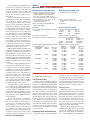
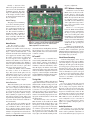
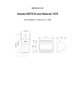
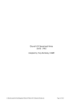
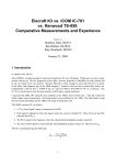
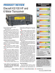
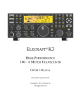
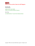
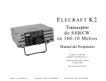
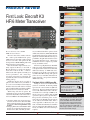
Key Measurements Summary product review 139 First Look: Elecraft K3 HF/6 Meter Transceiver 140 20 70 20 kHz Blocking Gain Compression (dB) 139 2 140 70 2 kHz Blocking Gain Compression (dB) I3 103 110 20 50 20 kHz 3rd-Order Dynamic Range (dB) I3 2 102 110 50 2 kHz 3rd-Order Dynamic Range (dB) I3 +26 +35 20 -40 Reviewed by Bruce Prior, N7RR ARRL Technical Advisor Elecraft entered the market with the K2, a rather good multiband low power (QRP) transceiver kit with a well-regarded receiver.1 Over time, with options the K2 developed into a 100 W SSB/CW radio with digital signal processing (DSP).2 Ideas about further improvements eventually outgrew the K2 box, so the folks at Elecraft decided to go back to the drawing board. The result is the K3, a softwaredefined radio with sophisticated DSP, great receiver performance, and a wide range of features and options in a handsome and ergonomically well-executed, but traditionallooking package. Unlike the K2, the K3 is not a kit of parts. It comes either factory assembled or as a solderless kit of fully tested and aligned modules. Festooned with surface mounted parts, in traditional kit form the K3 would be impractical for most amateurs to build. With a huge selection of options, K3 configurations range from about $1400 for a basic K3/10 (10 W) radio in kit form to well over $4000 for a K3/100 (100 W), fac1L. Wolfgang, WR1B, “Elecraft K2 HF Transceiver Kit,” Product Review, QST, Mar 2000, pp 69-74. QST Product Reviews are available on the Web at www.arrl.org/members-only/ prodrev/. 2L. Wolfgang, WR1B, “Elecraft KPA100: A 100 W Upgrade for Your Elecraft K2 HF Transceiver,” Product Review, QST, Feb 2004, pp 76-80. tory assembled with all the options. Check out Elecraft’s Web site (www.elecraft.com) for full details of the many options and configurations available. With the wide range of possibilities, the QST staff decided to review two separate K3 transceivers: a bare-bones modular kit and an as-complete-as-possible factory assembled version. This review spotlights the basic K3/10 kit with an overview of the kit building process, a description of the features and a somewhat abbreviated battery of ARRL Lab tests. Later this year we’ll take a closer look at an assembled K3/100 loaded up with options (some are not yet available) and with more mature firmware, and perform additional ARRL Lab testing. The Basic K3/10: A QRP Super-Rig Selling for $1399.95 in modular kit form ($1599.95 assembled), the K3/10 probably represents the current summit of QRP level transceivers. The basic K3/10 transmits and receives CW, SSB and data modes on all amateur bands from 1.8 through 54 MHz at the 10 W power level. Adding AM and FM operation requires just two optional filters. Except for the transmitter power, it’s the same radio as the K3/100. Any K3 options can be added to the K3/10 model, and it’s easily upgraded to 100 W any time you want. Assemble the built and tested modules and you end up with a K3/10 identical to the factory assembled version. No soldering is required. Mark J. Wilson, K1RO Product Review Editor 20 kHz 3rd-Order Intercept (dBm) I3 2 +26 +35 -40 2 kHz 3rd-Order Intercept (dBm) T-R 50 22 10 Tx-Rx Turnaround Time (ms) I3 TX -20 -27 Transmit 3rd-Order IMD (dB) -35 I9 TX -20 -53 Transmit 9th-order IMD (dB) -70 pr029 80 M Key: Dynamic range and intercept values with preamp off. Intercept values were determined using –97 dBm references. 20 M Bottom Line Elecraft’s K3/10 modular kit is easy and enjoyable to assemble. Once built, you’re rewarded with a feature-laden transceiver with receiver performance rivaling the best available at any price. You can customize your radio with a wide range of options at any time as your interests and needs change. [email protected] From April 2008 QST © ARRL I’m an enthusiastic kit builder who has a well-deserved reputation in the Pacific Northwest QRP Group as “Dr Klutz.” If anybody can figure out how to flub a kit assembly, I’m that person. It turned out that the K3 module kit is Bruce-proof. Well, almost. Taking over the dining room table, I assembled the bare-bones K3, serial number 158, in about 11 hours on a brand new static-dissipating work mat. The egg carton I used to sort the K3 hardware only had 12 compartments. Monday morning quarterbacking tells me that I should have used an 18 compartment carton. Using 12 compartments, I sorted screws by type, but not by size. When I was very close to finishing the kit, I was short three 1⁄4 inch black pan-head screws to attach three transistors for heat sinking. I apparently had used some 1⁄4 inch screws where 3⁄16 inch ones had been specified. Luckily, Elecraft had supplied extra 1 ⁄4 inch zinc pan-head screws, so I could complete the assembly. Later, Elecraft sent replacements for the screws I “lost.” Building this modular kit with help from its lavishly-illustrated K3 Assembly Manual (available as a PDF download from the Elecraft Web site) seemed almost too easy. The only moderately challenging stage was fitting the front panel circuit board assembly to the main RF board. It took me about five minutes of fiddling before they fit neatly together. I would recommend building the kit to anybody who is physically able. It gave me an appreciation for the superb engineering that has gone into the K3, something I wouldn’t have experienced with the factoryassembled version. Once completed, I was amazed how much space was left in the box. Some of that space is reserved for the 100 W amplifier, antenna tuner and subreceiver options, but even with those installed there will still be plenty of space available for further hardware enhancements. Did it work? Well, not quite at first. I plan to eventually install an FM roofing filter in slot 1, so I put an optional 6 kHz filter in slot 2 and the standard 2.7 kHz filter in slot 3. It turns out that the K3 defaults to expect a filter in slot 1. After enabling the appropriate filter parameters in the CONFIG menu, the K3 sang happily. The Elecraft K3 Utility is available to update the transceiver to the latest firmware versions within a few minutes. It’s a good idea to check Elecraft’s Web site after assembly to see if there is a newer version available. The K3 can be connected to a computer via a USB-to-serial cable, available as an option from Elecraft, or by an ordinary serial-to-serial cable, and the software can then be instructed to search From April 2008 QST © ARRL Table 1 Elecraft K3/10, serial number 00158 Manufacturer’s Specifications Measured in the ARRL Lab Frequency coverage: Receive, 0.5-30, 48- 54 MHz;* transmit, 1.8-2, 3.5-4, 5.3305, 5.3465, 5.3665, 5.3715, 5.4035, 7-7.3, 10.1-10.15, 14-14.35, 18.068-18.168, 21-21.45, 24.89-24.99, 28-29.7, 50-54 MHz. Receive and transmit, as specified. Power requirement: 11-15 V dc (13.8 nom.); receive, 0.9 A (signal present); transmit, 4 A (10 W out). Receive, 0.91 A; transmit, 3.1 A; tested at 13.8 V dc. Operation confirmed at 11 V. Modes of operation: SSB, CW, AM, FM, PSK31, FSK, AFSK.** As specified. Receiver CW sensitivity, 500 Hz bandwidth: –136 dBm (preamp on) Receiver Dynamic Testing Noise Floor (MDS), 400 Hz bandwidth:† Preamp Off On 14 MHz –130 –137 dBm 50 MHz –128 –135 dBm Noise figure: Not specified. 14 MHz, preamp off/on: 18/11 dB. Blocking gain compression: 140 dB typical. Gain compression, 500 Hz bandwidth: 20 kHz offset 5/2 kHz offset Preamp off/on Preamp off 14 MHz 139/134 dB 139/139 dB 50 MHz 135/135 dB 134/132 dB Reciprocal Mixing (500 Hz BW): Not specified. 20/5/2 kHz offset: –116/–106/–95 dBc. Two-Tone IMD Testing Band/Preamp Spacing 14 MHz/Off 20 kHz Input level –27 dBm –15 dBm 0 dBm Measured Measured IMD level IMD DR –130 dBm 103 dB –97 dBm –52 dBm Calculated IP3 +25 dBm +26 dBm +26 dBm 14 MHz/On 20 kHz –38 dBm –23 dBm –137 dBm 99 dB –97 dBm +12 dBm +14 dBm 14 MHz/Off 5 kHz –28 dBm –15 dBm 0 dBm –130 dBm 102 dB –97 dBm –52 dBm +23 dBm +26 dBm +26 dBm 14 MHz/Off 2 kHz 50 MHz/Off 20 kHz –28 dBm –15 dBm 0 dBm –130 dBm 102 dB –97 dBm –52 dBm +23 dBm +26 dBm +26 dBm –28 dBm –14 dBm –128 dBm 100 dB –97 dBm +22 dBm +27 dBm for new K3 upgrades periodically. The K3 Driver’s Seat The basic features of the K3 are simple to learn. The three-page Quick-Start Guide in the K3 Owner’s Manual gets the ball rolling in short order. This feature-rich radio has much more to offer beyond simple receiving and transmitting, however. As with operating a high-performance automobile, these nuanced features take more time to learn. The Basic Operations section gives a lot of detail in 10 pages. The Advanced Operating Features section takes up an additional seven pages. Menu-accessed functions require more than five densely packed pages. Since much of the functionality of the K3 is driven by firmware, the list of features will surely grow and change. Consider this a snapshot of a moving target. Combating Noise and Interference Perhaps the single most powerful facility of the K3 is a wide range of interference and noise fighting aids. A classic problem in non-channelized Amateur Radio operation is to dig out a weak signal with one or more strong signals lurking nearby, and the K3 employs several tools to help with this. Roofing Filters The K3 provides for selectable roofing filters at the first IF to limit the off-frequency signals getting into the receiver — too many strong undesired signals may overload amplifier and mixer stages, causing internally generated spurious signals that reduce receiver performance. Note that the roofing filter’s job is only to protect the rest of the receiver, and that the operating bandwidth filtering is performed by the DSP. The basic K3 is equipped with a 5 pole 2.7-kHz roofing filter that can be changed to an 8 pole 2.8-kHz unit at time of order. Other 8 pole roofing filters are available for 6, 2.1, 1.8 and 1 kHz, as well as 400 Hz and QS0804-PR01 Receiver Second-order intercept: Not specified. Receiver Dynamic Testing Preamp off/on: +79/+79 dBm. S-meter sensitivity: S9, 50 µV (adjustable). S9 signal at 14.2 MHz: preamp off, 50 µV; preamp on, 14 µV. Audio output power: 2.5 W into 4 Ω at 10% THD. 2.8 W at 10% THD into 4 Ω. IF/audio response: Not specified. Range at –6 dB points, (bandwidth): CW (400 Hz): 455-840 Hz (385 Hz),‡ Equivalent Rectangular BW: 364 Hz; USB: 306-2827 Hz (2521 Hz); LSB: 373-2898 Hz (2592 Hz); AM: 202-2802 Hz (2600 Hz). Spurious and image rejection: 70 dB. First IF rejection, 14 MHz, 98 dB; 50 MHz, 96 dB; image rejection, 14 MHz, 109 dB; 50 MHz, 71 dB. Transmitter Power output: 1.8-14 MHz, 10 W; 18-54 MHz, 10 W (CW, FM), 8 W (SSB); AM not specified. Transmitter Dynamic Testing HF: CW, SSB, typically 12 W high, <1 W low; 50 MHz: CW, SSB, typically 8 W high, <1 W low. Spurious and harmonic suppression: HF, 50 dB; VHF, 60 dB. HF, 50 dB; VHF, 61 dB. Meets FCC requirements. Third-order intermodulation distortion (IMD) products: Not specified. (at 8 W) 3rd/5th/7th/9th order (worst case band): HF, –27/–40/–47/–53 dB PEP; VHF, –28/–43/–47/–50 dB PEP. CW keyer speed range: Not specified. 8 to 65 WPM. CW keying characteristics: Not specified. See Figures 1 and 2. Transmit-receive turnaround time (PTT release S9 signal, 22 ms (SYNC DATA mode). to 50% audio output): Not specified. Unit is suitable for use on AMTOR. Composite transmitted noise: Not specified. 0.01 0.02 0.03 0.04 0.05 0.06 0.07 0.08 Figure 1 — CW keying waveform for the Elecraft K3/10 showing the first two dits in full-break-in (QSK) mode using external keying. Equivalent keying speed is 60 WPM. The upper trace is the actual key closure; the lower trace is the RF envelope. (Note that the first key closure starts at the left edge of the figure.) Horizontal divisions are 10 ms. The transceiver was being operated at 10 W output on 14.2 MHz. QS0804-PR02 0 -20 -40 See Figure 3. Size (height, width, depth): 4.0 × 10.7 × 11.8 inches; weight, 6 pounds (8.5 pounds for the 100 W version, all options installed, not including power supply or external accessories). Price: K3/10 kit version, $1399.95 ($1599.95 assembled); KFL3A-6K 8-pole, 6 kHz roofing filter, $120; KFL3A-400 8-pole, 400 Hz kHz roofing filter, $120. *Reduced sensitivity around the 8.215 MHz IF. The optional KBPF3 bandpass filter is required for full general coverage receive. **FM and AM require optional IF filters. †The optional KFL3A-400 8-pole, 400 Hz roofing filter was used for optimum performance. The noise figure is approximately 1 dB less than the 500 Hz filter. ‡Varies with pitch control setting. 250 Hz. The 6 kHz filter is required for AM transmission. A wider 8 pole FM-bandwidth filter was not yet available at press time. Other 5 pole roofing filters are available for 500 Hz and 200 Hz. There are five filter slots available on the main RF board and another five can be used on the forthcoming KRX3 subreceiver. Once again, you don’t need a narrow roofing filter to operate at narrow bandwidths (say 500 Hz) in CW or data modes — bandwidth filtering is provided by the DSP. But installing one will improve dynamic range at very close signal spacings. Unless you plan to use the radio in demanding environments with lots of strong signals on adjacent frequencies, you may not need anything more than the stock 2.7 kHz unit. I’ve ordered the 6 kHz and FM bandwidth filters to be able to operate AM and FM, but am not adding any more for now. The ARRL Lab added an 8 pole 400-Hz roofing filter for testing. As shown in Table 1, 0 the results are impressive. Overall receiver performance is right up there with the best radios the Lab has ever measured, and this is the first receiver we’ve tested with better than 100 dB IMD dynamic range at the closer signal spacings. Bandwidth and Shift Filtering DSP bandwidth and shift filtering are coordinated automatically with whatever suite of roofing filters is installed. There are four kinds of filtering: bandwidth and shift for CW and phone, dual passband for CW, and dual-tone for RTTY. The K3 DSP bandwidth filter can be adjusted as narrow as 50 Hz and it still sounds fine without ringing — a remarkable accomplishment. A special dual passband filter designed for CW combines a steep-skirted narrow filter focused on the signal of interest with a broad-skirted variable wide filter that allows the operator to hear adjacent activity as well at a lower volume. -60 -80 -100 14015 14017 14019 14021 14023 14025 Figure 2 — Worst-case spectral display of the Elecraft K3/10 transmitter during keying sideband testing. Equivalent keying speed is 60 WPM using external keying. Spectrum analyzer resolution bandwidth is 10 Hz, and the sweep time is 30 seconds. The transmitter was being operated at 10 W PEP output at 14.2 MHz. 0 -20 -40 -60 -80 -100 -120 -140 -160 -180 10 2 QS0804-PR03 10 3 10 4 10 5 10 6 Figure 3 — Worst-case spectral display of the Elecraft K3 transmitter output during composite-noise testing. Power output is 10 W at 14.2 MHz. The carrier, off the left edge of the plot, is not shown. This plot shows composite transmitted noise 100 Hz to 1 MHz from the carrier. From April 2008 QST © ARRL frequency adjustment. Finally, a dual-tone filter with its two peaks (for mark and space tones) is the standard filter for RTTY operation. The filter shapes are illustrated graphically on the display and their values are displayed momentarily when they are adjusted. RTTY Without a Computer Standard or reversed 45 baud RTTY can be decoded on a scrolling K3 display, and the CW keyer can be used to transmit FSK RTTY directly from the K3 with no computer interface required. Send CW, out comes RTTY. Any Notch Filtering of the eight CW message memoThe purpose of notch filtering ries can be programmed with is to remove interfering narrowRTTY messages. band interference such as a carThere is a 5 second pause rier or CW signal. The K3 has before the RTTY transmit diddle two different kinds of notch filswitches off when controlled by ters. The manual notch filter is the keyer, giving the operator tunable from 200 to 3920 Hz. It some ear-scratching time while works in any mode. The autotransmitting. A useful prosign IM matic notch filter will find and can be inserted at the end of transattenuate a single tone and works mitted text to switch immediately in any voice mode. to receive mode. A nonprinting Figure 4 — There’s a lot of room inside the K3/10 for double-dash (BT) prolongs the Noise Blanker options and upgrades such as an antenna tuner, diddle time. The K3 includes a rather 100 W amplifier or second receiver. Similar receive/transmit facilitraditional 1st IF (8215 kHz) hardware noise blanker with a wide range that results in better intelligibility and lower ties are planned for other digital modes such of adjustments when active. It has width set- listener fatigue. Once a sweet spot is found, as PSK31. With or without the optional tings — narrow, medium and wide — that turning the NR on and off can demonstrate 100 W amplifier installed, the K3 is said to be robust enough to allow full power operadetermine the width of the offending signal a dramatic contrast. tion in 100% duty cycle modes. to be suppressed. Another setting controls the relative aggressiveness of suppression in seven steps. As a noise suppressor, the hardware noise blanker creates holes in the waveform. This hardware noise blanker is useful to fight broadband hash originating from sources such as noisy ac power lines and motor vehicle ignition systems. A DSP noise blanker at the 15 kHz IF also offers a choice of 21 different settings. This system attacks pulse noise by substituting signal in place of the noise instead of creating a hole. It’s most effective against artificial electronic noise from sources such as a nearby computer. Noise Reduction When the automatic gain control (AGC) is active, a DSP noise reduction (NR) system can be employed with 16 different settings to attenuate the random noise that is ever-present in the radio spectrum. The NR system can produce dramatic changes in the readability of signals in any location and with any antenna system. Time spent experimenting with just the right adjustment for various modes and band conditions is most worthwhile. Just among the noise blanker and the noise reduction systems there are 7056 active combinations. Noise control engineering is complex, and the operator needs to work with tradeoffs: Heftier noise control is usually accompanied by increased audio distortion, so a compromise needs to be found From April 2008 QST © ARRL RIT and XIT The usual receive or transmit incremental tuning (RIT/XIT) labels show up in the display. Changes in the RIT are shown on the VFO A display and changes in XIT are indicated momentarily on the VFO B display. In addition, three LEDs on the lower-right corner of the front panel indicate whether the adjustment is lower in frequency, centered or higher. Another LED near the PHONES socket lights whenever the transmit and receive frequencies differ. Tuning Aids A long-standing problem with CW and digital modes has been accurate tuning, and the K3 has three facilities to help. One is the SPOT button, which emits sidetone audio at the correct pitch, allowing the operator to tune the received signal to match the sidetone frequency. The second facility is the CW/data tuning (CWT) button, which enables a visual tuning display. The incoming signal can then be tuned to coincide with the CWT pointer. The third facility is the real winner: With the CWT circuit enabled, the SPOT button automatically slides the K3 to join the frequency of the incoming signal. CW operators will appreciate the fact that they can continue copying while the K3 adjusts the frequency for zero-beat. The same auto-spot function works with PSK31, but may require some manual tweaking for fine Visual Morse Decoding A CW decoding display can be chosen for both transmitted and received Morse code. This display is especially useful for instilling in the CW operator the discipline of leaving proper spacing between words. Operators may chose to have the display operate only while transmitting. This facility can be set manually for a given code speed or allowed to float automatically within presets. Yes, it also allows beginning CW contesters to read Morse code faster than their normal skill level. Tuning It’s easy to change bands with repeated presses of the BAND up or down buttons, or you can jump to any frequency within the K3 range via direct keypad entry. The large VFO A knob changes receive and transmit frequencies simultaneously unless the K3 is in SPLIT mode, in which case the VFO B knob controls the transmit frequency. If the RIT or XIT is not active, the RIT/XIT encoder can be configured to act as a coarse tuner of VFO A for a very rapid frequency change (QSY) or for quickly “taking the pulse” of band conditions. Audio Equalization Some operators care a great deal about receive and transmit audio quality. The K3 features audio equalization adjustments on receive and transmit. Frequency response can be custom tailored in eight bands in increments of 1 dB within the range of ±16 dB. These adjustments help compensate for variations in speaker/headphone or microphone frequency responses or the acoustical characteristics of the operational environment to faithfully reproduce the original audio or to enhance intelligibility. The transmit voice signal audio equalization quality can be monitored simultaneously in headphones without transmitting. Pseudo-Stereophonic Audio An “Audio Effects” (AFX) mode feeds received audio to stereophonic earphones or stereophonic external speakers with a slight adjustable lag between left and right sides. The result is a textured listening experience that I found considerably less fatiguing than monaural audio, especially during extended operating sessions. Having discovered the AFX, I refuse to turn it off. Both phone and CW listening is much improved, especially using stereophonic headphones. Upgrades and Changes Elecraft has an established reputation for listening carefully to user feedback and in many cases responding to that feedback by making changes in their products. That’s been the case with the K3, beginning with the early beta testers and continuing as radios are delivered and put into use. The K3, very largely a software-defined radio, was designed specifically to allow for changes through firmware, and a number of well documented updates have appeared on Elecraft’s Web site. Some issues have required hardware changes. Initial ARRL Lab testing revealed that transmit-receive turnaround time was too long for AMTOR operation. Elecraft released a modification that solved this problem and improved AGC operation. Another change (a single capacitor) improved the CW keying waveform and fixed an issue with shortening of the first transmitted character. These changes are included in current production radios. Owners of early radios should contact Elecraft for more information. Initial Lab testing also showed worse than expected transmitter IMD performance. We measured third order IMD products at about –23 dB worst case, and Elecraft indicated that it should be significantly better. We confirmed this by measuring transmitter IMD at the low power amplifier output on a K3/100, and measured the recorded –27 dB with their new guidline (below). At press time we were working with Elecraft to locate the problem in the review K3/10. We’ll have more on this in the follow-on K3/100 review. For now, Elecraft recommends that for best SSB transmit IMD performance on 17 meters and higher, set the power output to 8 W or less. I do have a short “wish list.” The date formats offered so far are US: MM.DD.YY and EU: DD.MM.YY. The SI (metric) format could also be added as an option — SI: YY.MM.DD. It would be great if the Elecraft engineers could find a way to allow auto notch to work on CW, without notching out desired CW signals. This is probably a tall programming challenge, but something that many CW operators would appreciate. Nitpicking: I’d like to see a heftier thumbscrew ground post to accommodate heavier wire. The Anderson PowerPole system for the high-current dc power input has a tendency to disconnect with little force. That’s only a minor irritant in a fixed installation, but it could become a more significant problem in a vibration-prone mobile environment. The K3 Owner’s Manual is available online. The K3 is complex enough and changes are made often enough that an updateable index would be helpful. As firmware changes are made over time, perhaps new or revised items could be color-coded so that users could scan the revised index and key in on the most recent changes. Final Thoughts Finishing the K3/10 can be your final destination, and you’ll have a QRP transceiver rich in features and basic radio performance. Or you can view it as a starting point, adding a 100 W amplifier, automatic antenna tuner, more filters, an interface for a transverter or separate receive antenna, a second receiver and more. Full details are available on Elecraft’s Web site, along with detailed technical information and explanations of all aspects of the radio’s operation and a very active user’s e-mail reflector. Manufacturer: Elecraft Inc, PO Box 69, Aptos, CA 95001; tel 831-662-8345; www.elecraft.com. From April 2008 QST © ARRL