1
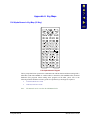
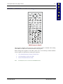
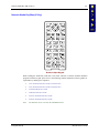
x
Table of Contents
Illustrations
Figure 1-1 The MX1 Hand Held Computer...................................................................................................... 1
Figure 1-2 MX1 Components ........................................................................................................................... 7
Figure 1-3 Open Battery Door .......................................................................................................................... 8
Figure 1-4 Inserting Battery Pack ..................................................................................................................... 8
Figure 1-5 MX1 With Handstrap...................................................................................................................... 9
Figure 1-6 Upper Strap Bracket........................................................................................................................ 9
Figure 1-7 Strap Inserted in Upper Bracket ...................................................................................................... 9
Figure 1-8 Pistol-Grip Handle and Contacts on the Back of the MX1 ........................................................... 11
Figure 1-9 Connect Handle to MX1 ............................................................................................................... 12
Figure 1-10 Location of the Power Button ..................................................................................................... 13
Figure 1-11 Scanner Endcap........................................................................................................................... 15
Figure 1-12 Scanner / RS-232 Endcap............................................................................................................ 15
Figure 1-13 RS-232 Endcap ........................................................................................................................... 15
Figure 1-14 Plain Endcap................................................................................................................................ 16
Figure 1-15 Scanner Endcap LEDs and Beeper.............................................................................................. 16
Figure 1-16 MX1 Endcap with O-Ring Gasket .............................................................................................. 18
Figure 1-17 Endcap and ZIF Ribbon Connector............................................................................................. 18
Figure 1-18 Insert / Remove PC Card............................................................................................................. 20
Figure 2-1 System Hardware .......................................................................................................................... 27
Figure 2-2 Location of the Power (PWR) Button ........................................................................................... 30
Figure 2-3 Power Status and the Status LED.................................................................................................. 31
Figure 2-4 MX1 Display................................................................................................................................. 33
Figure 2-5 Keypads......................................................................................................................................... 37
Figure 2-6 Three Special Use Keypads........................................................................................................... 38
Figure 2-7 Infrared Port - COM2 Port ............................................................................................................ 41
Figure 2-8 9-Pin RS-232 Description ............................................................................................................. 43
Figure 2-9 Scanner Endcap LEDs and Beeper................................................................................................ 44
Figure 2-10 Handle Contacts .......................................................................................................................... 45
Figure 2-11 Battery Charging Contacts .......................................................................................................... 45
Figure 3-1 Battery Compartment .................................................................................................................... 47
Figure 3-2 Main Battery Pack......................................................................................................................... 48
Figure 3-3 Battery and Battery Charging Cup ................................................................................................ 48
Figure 3-4 Multidock and Single Dock Communicating Charger .................................................................. 52
Figure 3-5 Insert MX1 in Cradle .................................................................................................................... 52
Figure 3-6 Clip-on Portable Charger .............................................................................................................. 53
Figure 5-1 MX1 RS-232 Endcap Serial Connector (COM1) and Pinout ....................................................... 91
Figure 5-2 RS-232 Endcap COM Port Loopback Configuration ................................................................... 92
Figure 5-3 MX1 RS-232/Scanner Endcap Serial Connector (COM1) and Pinout ......................................... 92
Figure 5-4 RS-232/Scanner Endcap COM Port Loopback Configuration...................................................... 92
MX1 Reference Guide
E-EQ-MX1RG-D