1
First Steps
7
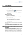
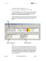
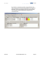
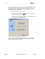
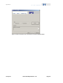
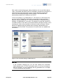
Make some test moves with the individual axes using the controls
on the Axes tab card:
The first moves should be made in open-loop operation (Servo
boxes must be unchecked). With the E-517, open-loop
commanding means to give the desired output voltage values for
the axes. Command an output voltage of 0 V by entering 0 in the
Openloop Value field of an axis and pressing Enter on your
keyboard. Then enter a new value of about 10% of the axis voltage
range and press Enter. Increment the Openloop Value this way by
steps of a suitable size, up to the upper voltage limit of the axis
(see datasheet or measurement protocol of the mechanics), and
then reduce it in an analogous manner to the lower voltage range
limit of the axis. In doing so, observe the position display for the
axis (in the Position field) and the current output voltage for the
corresponding piezo actuator in the stage (in the Voltage field of
the Piezo channels tab card). The output voltage values should
follow the commanded values. At 0 V output voltage, the current
position value of the axis should be approximately 0 μm, but due to
the calibration settings of the system, the axis position can differ
from 0 by about 20% of the axis travel range.
You can also use the < and > buttons to decrement / increment the
commanded value by the value given in the Step size field (1.0 V in
the figure below).
If open-loop operation is successful, you can switch to closed-loop
operation by checking the Servo boxes on the Axes tab card (see
www.pi.ws
E-517 PZ214Equ Release 1.0.0
Page 17