1
Configuration
Advanced
Digital Input/Output
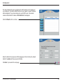
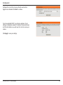
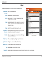
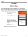
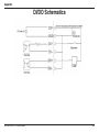
This screen allows you to control the behavior of digital input and digital output devices. The I/O connector provides the physical
interface for digital output (DO) and digital input (DI) that is used for connecting a diversity of external alarm devices such as IR-Sensors
and alarm relays. The digital input is used for connecting external alarm devices and once triggered images will be taken and e-mailed.
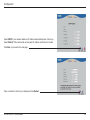
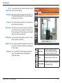
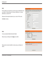
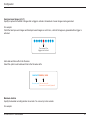
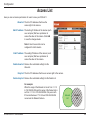
Select D/I or D/O Mode: The camera will send a signal when an event
is triggered, depending upon the type of device
connected to the DI circuit.
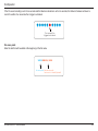
N.C. stands for Normally Closed. This means that
the normal state of the circuit is closed. Therefore
events are triggered when the device status changes
to Open.
N.O. stands for Normally Open. This means that
the normal state of the circuit is open. Therefore
events are triggered when the device status changes
to Closed.
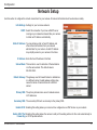
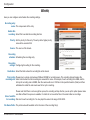
LED: You may specify whether or not to illuminate the
LED on the side of the camera.
Video Output: Enable/ disable the BNC terminal TV output signal.
D-Link DCS-6511 User Manual
56