1
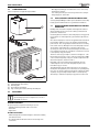
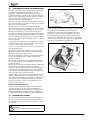
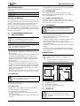
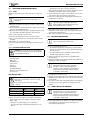
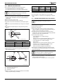
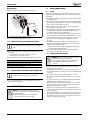
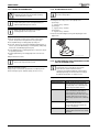
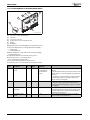
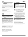
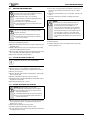
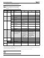
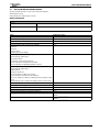
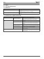
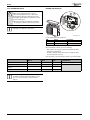
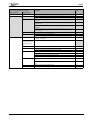
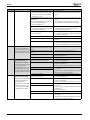
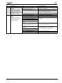
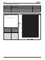
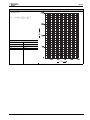
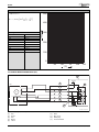
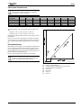
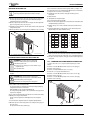
MOUNTING AND INSTALLATION WATER TREATMENT PRODUCTS Suitable water treatment products can be obtained from the following manufacturers: FERNOX SENTNEL 0870 601 5000 or www.fernox.com 0800 389 4670 or www.sentinel-solutions.net Table 5 • Fit the bypass valve as near as possible to the heating system and as far away as possible from the buffer vessel. 5.2.4 EXPANSION VESSEL Install an additional expansion vessel on the heating system return between the bypass valve and the hybrid manager. Size the expansion vessel according to EN128-28. ARTIFICIALLY SOFTENED WATER 5.2.5 THERMOSTATIC RADIATOR VALVES It is possible to have an ion exchange water softener fitted to the cold water system of the property. However, the boiler requires an untreated cold water connection taken from the mains supply, before the water softener, to the primary water filling point of the heating system. For optimum comfort and system efficiency a thermostatic radiator valve should be fitted to each radiator within the circuit, except for the radiator in the same room as the room controller. 5.2.6 HYBRID MANAGER Alternatively there are water softening/treatment devices that do not adjust or alter the pH levels of the water. With these devices it may not be necessary to provide an untreated water by-pass to the primary water filling point of the heat system. SYSTEM COMPONENT CONFIGURATION 5.2.1 GENERAL REQUIREMENTS The following requirements must be met. The following sections detail additional requirements for the installation of the individual system components. It is important the pump speed is set correctly, please set the HE pump inside the hybrid manager ( chapter 6.2.9, page 35). • The permissible maximum length of the refrigerant lines between the external unit and the hybrid manager is 30 m with up to 15 bends (single direction). • The permissible minimum length of the refrigerant lines between the external unit and the hybrid manager is 1 m in a single direction. • A height differential between the installation site and the hybrid manager is permissible. However, take the maximum pipe length of 30 m into account. • If the hybrid manager is mounted above the heat source, fit an automatic air vent valve at the highest point of the heating system. • The maximum equivalent length of pipe work with which the hybrid manager is connected to the existing heating system flow and return should be determined from tables 50 and 51. One metre must be subtracted for each 90° bend. • Rooms where the hybrid manager or the refrigerant lines are installed must have a volume of at least 5.7 m³, if the room can be occupied. Information on the installation site: • Ensure minimum clearances are maintained. • Mount the hybrid manager on to a fixed rigid wall capable of supporting the weight of the unit. • To reduce the installation effort we recommend the installation of the hybrid manager below the heat source ( Fig. 7, page 9). • Flow and return pipes can be routed vertically from the top or bottom into the hybrid manager. • Refrigerant lines can be routed vertically from the top into the hybrid manager. • If refrigerant lines are to be routed downwards, allow for adequate space to route the pipes downwards alongside the unit, preferably on the left hand side. MINIMUM CLEARANCES Dimensions given are minimum clearances around the Hybrid manager for the purposes of installation and service. The minimum volumetric requirements of the room size must also be adhered to according to EN: 14511. a d 5.2.2 BUFFER TANK d c b NOTICE: ▶ Please refer to the Buffer tank installation instructions for correct hydraulic connection. 6720803687-28.1Wo 5.2 WARNING: Rooms where the hybrid manager or the refrigerant lines are installed must have an internal volume of at least 5.7 m3, if the room can be occupied. Fig. 16 Minimum clearances, hybrid manager The buffer tank must be installed in series in the flow between the hybrid manager and the system by-pass. 5.2.3 BYPASS VALVE [a] [b] [c] [d] The bypass valve is connected between the flow out from the buffer vessel and the first radiator on the heating system. 5.2.7 EXTERNAL UNIT Further requirements of the installation site: • The bypass valve must be fitted into a straight pipe section and not immediately near a bend. • For commissioning and maintenance the bypass valve must be easily accessible. 6 720 803 687 (2012/11) Top clearance: 250 mm Bottom clearance: 200 mm Front clearance: 800 mm for maintenance Side clearance: 5 mm DANGER: ▶ Never site the external unit in locations where flammable gases could be released, accumulate or flow past. 21