1
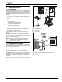
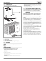
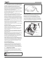
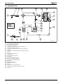
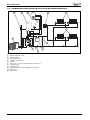
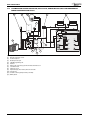
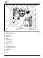
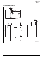
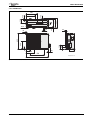
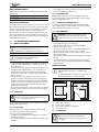
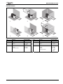
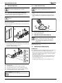
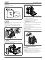
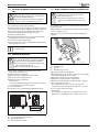
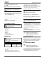
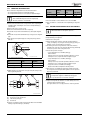
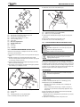
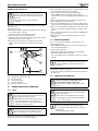
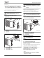
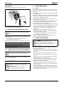
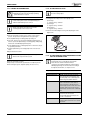
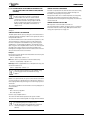
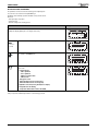
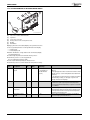
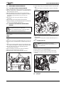
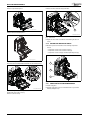
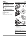
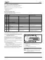
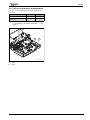
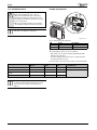
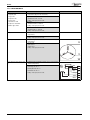
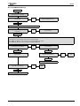
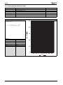
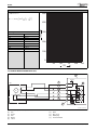
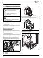
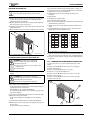
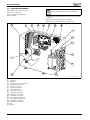
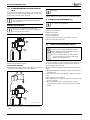
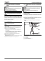
MOUNTING AND INSTALLATION 5.3 PRE-INSTALLING PIPES 5.3.2 FITTING THE BYPASS VALVE Regarding the arrangement and position of the bypass valve, observe the information in section 5.2.3. Contamination in the system can result in damage to the air to water heat pump and reduce the output. 5.3.1 PREPARING THE HYBRID MANAGER CONNECTION ▶ Installing on-site pipe work. For this, observe the information on system component configuration ( chapter 5.2). Pipe work may be routed vertically or behind the appliance. ▶ Connect the bypass valve between the heating system flow and return. ▶ Install the bypass valve in the flow direction from the flow to the return. The flow direction is identified on the bypass valve by an arrow. ▶ Drill six holes into the wall using the drilling template provided [1]. ▶ Insert suitable wall plugs. ▶ Fit the mounting plate of the hybrid manager to the wall using the top drilled holes [2]. 2 1. 2. 1 6 720 646 970-14.2ITL Fig. 22 Mounting the bypass valve in flow direction [1] [2] From the heating system flow To the heating system return 5.3.3 MOUNTING THE FW200 PROGRAMMING UNIT The FW200 must never be fitted in the front of the gas appliance, and must not be placed in direct sun light. The programming unit is mounted on the wall and it is electrically linked via the hybrid control module via CANBUS cable. 6720803687-27.1Wo Fig. 20 Fitting the mounting plate ▶ Connect the heat source pipe work and that of the heating system to the mounting plate. Ensure your connections are correct ( Fig. 21). – Fit the pipe fully into the pipe connection. – Tighten the compression fitting. All installation information for the FW200 can be found in the separate FW200 installation manual. 5.4 MOUNTING THE HYBRID MANAGER PREREQUISITES 1 2 3 4 Prior to starting the mounting of the hybrid manager, ensure that the onsite conditions have been met ( chapter 5.2, from page 21). • Where the unit is being fitted to an existing heating system ensure the system has been flushed and cleaned prior to fitting of the Hybrid manager unit ( chapter 5.1.1). • The required minimum clearances are ensured ( chapter 5.2.6). • The mounting plate has been secured to the wall and is correctly connected ( chapter 5.3.1). • The bypass valve has been fitted correctly ( chapter 5.3.2). 5 6 720 646 970-13.2ITL Fig. 21 Hybrid manager mounting plate [1] [2] [3] [4] [5] Mounting plate Heating system return (22 mm compression fitting) Pipe work to the heat source (22 mm compression fitting) Pipe work from the heat source (22 mm compression fitting) Heating system flow (22 mm compression fitting) NOTICE: Buffer tank installation: ▶ refer to the instructions provided with the buffer tank. 24 6 720 803 687 (2012/11)