1
MAGNUM ETX
Biscuit Format Single Board PC
User Guide
Document Reference: Product User Guide
Document Issue: 1.0
Page | 1
MAGNUM ETX
Table Of Contents
Contents
Copyright ............................................................................................................................................................ 4
Limitations of Liability ....................................................................................................................................... 4
Trademarks ......................................................................................................................................................... 4
Regulatory Statements ........................................................................................................................................ 5
Safety Warning for North America .................................................................................................................... 5
Manual Organisation .............................................................................................................................................. 6
Introduction ............................................................................................................................................................ 7
Specification ....................................................................................................................................................... 8
General Precautions .............................................................................................................................................. 10
PS/2 Devices ..................................................................................................................................................... 10
Electro-Static Discharges.................................................................................................................................. 10
On-Board Battery ............................................................................................................................................. 10
BIOS & CMOS Memory .................................................................................................................................. 11
Electromagnetic Compatibility ......................................................................................................................... 11
Quick Start ............................................................................................................................................................ 12
Assembly .......................................................................................................................................................... 13
Daughter Board connector locations ............................................................................................................. 13
Cooling ......................................................................................................................................................... 15
Stack Heights and Clearances ....................................................................................................................... 17
Connections ...................................................................................................................................................... 18
J1 PCI VIO Select......................................................................................................................................... 19
J2 Vcc LCD ................................................................................................................................................... 19
SW1 Power + CF Selector ............................................................................................................................ 19
P1 Auxiliary USB ......................................................................................................................................... 20
P7 Parallel Port ............................................................................................................................................. 20
P8 SMI Bus................................................................................................................................................... 20
P9 IDE Connector ......................................................................................................................................... 20
P10 Power On / Reset ................................................................................................................................... 21
P11 Fan Connector ....................................................................................................................................... 21
P12 Power ..................................................................................................................................................... 21
P14 GPIO Audio ........................................................................................................................................... 21
P15, P16 P17 LCD/LVDS Support............................................................................................................... 22
System Software ................................................................................................................................................... 24
Operating System Install................................................................................................................................... 24
Operating System API Functions ................................................................................................................. 24
System BIOS ........................................................................................................................................................ 25
BIOS Menus ..................................................................................................................................................... 25
Main Menu ................................................................................................................................................... 26
Advanced Menu ............................................................................................................................................ 27
Page | 2
MAGNUM ETX
Table Of Contents
Power Menu .................................................................................................................................................. 30
Security Menu............................................................................................................................................... 31
Boot Menu .................................................................................................................................................... 32
Exit Menu ..................................................................................................................................................... 33
Maintenance ......................................................................................................................................................... 34
Amendment History ......................................................................................................................................... 35
Page | 3
MAGNUM ETX
Introduction
Copyright
All rights reserved. No part of this publication may be reproduced, stored in any retrieval system, or transmitted,
in any form or by any means, electronic, mechanical, photocopied, recorded or otherwise, without the prior
permission, in writing, from the publisher. For permission in the UK please contact Blue Chip Technology.
Information offered in this manual is believed to be correct at the time of printing. Blue Chip Technology
accepts no responsibility for any inaccuracies. The information contained herein is subject to change without
notice. There are no express or implied licences granted herein to any intellectual property rights of Blue Chip
Technology Ltd.
Limitations of Liability
In no event shall Blue Chip Technology be held liable for any loss, expenses or damages of any kind
whatsoever, whether direct, indirect, incidental or consequential, arising from the design or use of this product
or the support materials supplied with this product. If this product proves to be defective, Blue Chip Technology
is only obliged to replace or refund the purchase price at Blue Chip Technology's discretion according to their
Terms and Conditions of Sale.
Trademarks
All trademarks and registered names acknowledged.
IBM, PC, AT and PS/2 are trademarks of International Business Machines Corporation (IBM).
VIA is a registered trademark of VIA Technologies, Inc.
Phoenix BIOS is a trademark of Phoenix Technologies Inc
MSDOS and WINDOWS are registered trademarks of the Microsoft Corporation.
Linux is a registered trademark of Linus Torvalds.
Page | 4
MAGNUM ETX
Introduction
Regulatory Statements
CE
This product meets the essential protection requirements of the European EMC Directive (2004/108/EC) and the
Low Voltage Directive (2006/95/EC), and is eligible to bear the CE mark.
Warning
This is a Class A product. In a domestic environment this product may cause radio
interference in which case the user may be required to take adequate measures.
FCC
NOTE:
This equipment has been tested and found to comply with the limits for a Class A digital device, pursuant to
Part 15 of the FCC Rules. These limits are designed to provide reasonable protection against harmful
interference when the equipment is operated in a commercial environment. This equipment generates, uses, and
can radiate radio frequency energy and if not installed and used in accordance with the instruction manual, may
cause harmful interference to radio communications. Operation of this equipment in a residential area is likely to
cause harmful interference in which case the user will be required to correct the interference at his own expense.
WARNING:
Changes or modifications not expressly approved by the manufacturer could void the user's authority to operate
the equipment.
Safety Warning for North America
If the power lead (cord) is not supplied with the computer, select a power lead according to your local electrical
regulations. In the USA use a 'UL listed' lead. In Canada use a CSA approved or 'cUL listed' lead.
Si le cordon secteur n'est pas livré avec l'ordinateur, utiliser un cordon secteur en accord avec votre code
electrique nationale. En l'Etat Unis utiliser un cordon secteur 'UL listed'. En Canada utiliser un cordon secteur
certifié CSA, ou 'cUL listed'.
Page | 5
MAGNUM ETX
User Guide Organisation
Manual Organisation
This manual describes the Magnum ETX Single Board PC.
We have tried to include as much information as possible but we have not duplicated information that is
provided in the standard IBM Technical References, unless it proved to be necessary to aid in the understanding
of the product.
The manual is sectioned as follows:
Introduction;
Overview, listing the unit's features and specification;
Installation, including what software to install
Layout, showing where the various connectors are located, and their pin-out details;
How to upgrade the system;
Bios Setup
Connector Details
Design Considerations
Maintenance details
We strongly recommend that you study this manual carefully before attempting to interface with board or
change the standard configurations. Whilst all the necessary information is available in this manual we would
recommend that unless you are confident, you contact your supplier for guidance.
IT IS PARTICULARLY IMPORTANT THAT YOU READ THE SECTION 'PRECAUTIONS' BEFORE
HANDLING ANY COMPONENTS INSIDE THE UNIT.
If you have any suggestions or find any errors concerning this manual and want to inform us of these, please
contact our Technical Services department with the relevant details.
Page | 6
MAGNUM ETX
Product Summary
Introduction
The Blue Chip Technology Magnum ETX is the latest offering in the Biscuit format Single Board PC range,
integrating the latest advances in low power processor, memory, and I/O technologies to provide an ideal
platform for embedded applications. The Magnum ETX consists of a processor daughter card that complies with
the embedded ETX standard version 3.02, and a baseboard that contains the I/O interfaces. The concept of ETX
is to provide the user with a standard connector interface with fixed connector locations and predefined IO
functions. This modular approach provides a cost effective means of system upgrade and allows the user to
easily validate a number of CPU board price/power/performance options.
The product is available with CPU build options of Ultra Low Voltage VIA Eden 500Mhz, VIA C7 nanobga2
1GHz and the VIA C7 nanobga2 2GHz processors. On-board voltage regulator circuits provide the required
voltages for the processor from the incoming 5 volt power supply. The 500MHz version is targeted at lower
cost, power conscious, performance driven applications. Where reduced power is less of a requirement then the
1GHz and 2GHz versions offer a higher performance solution.
The processor maintains full backward compatibility with the 8086, 80286, i386 and Intel486 processors. It
supports both read and write burst mode bus cycles, and includes separate on-chip code and data caches which
employ a write-back policy. Cache is integrated within the CPU and operates at the full CPU frequency giving
excellent performance. Cache size is 128K L1 and 128K L2. Also integrated into the processor is an advanced
numeric co-processor which significantly increases the speed of floating point operations, whilst maintaining
backward compatibility with Intel486 math co-processor and complying with ANSI/IEEE standard 754-1985.
The memory interface supports up to 1GB of DDR2 SDRAM, in a standard 200 pin SODIMM socket.
The Magnum ETX utilises the VIA CN700 Northbridge and VT8237R Plus Southbridge to integrate many
peripherals. These include: VGA controller with CRT, LVDS and LCD interfaces, ATA-100 IDE interface,
10/100 Fast Ethernet controller, quad USB ports, dual serial ports, parallel port, real-time clock, keyboard and
mouse (PS/2) controller, AC’97 audio interface. The VT8237R also provides SATA interface which is accessed
via two SATA connectors positioned on the daughter board in accordance with the ETX V3.02 specification.
The MAGNUM ETX will drive a single PCI card, as well as mini-PCI and Compact Flash.
Page | 7
MAGNUM ETX
Specification
Specification
CPU
VIA ULV Eden 500MHz
VIA C7 nanobga2 1GHz/2GHz
Chipset:
VIA CN700 Northbridge
VIA VT8237R Plus Southbridge
BIOS:
Phoenix BIOS, with Ethernet Boot ROM option
Memory:
512MB to 1GB PC2-4200/5300 DDR2 400/533 SDRAM using
Horizontal 200 pin SODIMM, 1.8V operation.
DDR2 667MHz can be used but will operate at 533MHz
Cache:
128KB L1 and 128KB L2 Cache is integrated into the CPU
Onboard Peripherals
Graphics:
Integrated graphics controller based on the Unichrome Pro 3D/2D
Graphics controller. CRT, 18bit TFT LCD and LVDS SVGA up to 1920 x
1440 resolution
Ethernet:
Integrated controller providing 10/100 Base-T Ethernet
Boot ROM option within the BIOS setup for remote booting (PXE)
Note: the host board must carry the magnetic for network isolation
Storage:
Integrated into Southbridge, providing support for SATA 1 (dual ports dual
connectors) and ATA 133/100/66/33 EIDE HDD (quad ports, dual
connectors)
512MB I2C EEPROM providing non-volatile storage
Audio:
Integrated AC97 controller, Line In/Out, Microphone In
Communications:
Quad USB ver 2 compliant
Two 16C550 compatible serial ports
Note: Host board must provide transceivers
Parallel port giving SPP/EPP/ECP
Floppy Interface supporting single 1.44MB drive
Note: the floppy or parallel port operation is determined at boot time
By strapping a pin on the host board. The devices are mutually
exclusive
PS/2 compatible keyboard and mouse port
Monitoring:
CPU Core thermal monitoring
On board thermistor for system thermal monitoring
CPU Core, 1.8V, 2.5V, 3.3V and 5V voltage monitors
Hardware Watchdog timer with configurable timeout
BIOS or Software enabled/disabled. The time out results in a
System Reset
Miscellaneous:
PC standard Real time Clock is integrated into the Southbridge
The battery has to be located on the host board.
Speaker, Power/Reset switch, Hard Disk Activity LED, Suspend Switch
and external Lithium coin cell are all supported but located on the
Host board
Page | 8
MAGNUM ETX
Specification
Expansion Bus:
Single PCI v2.2 compliant slot with switchable 5V/3V signalling
Single Mini PCI expansion slot
Power:
5Volt only operation (5V ± 5%) with connectivity for +12V pass through
To PCI connector and Fan connector
5-Volt Power Consumption
7.5W, 500MHz with 512 MB RAM
8.5W, 1GHz with 512 MB RAM
12.5W, 2GHz with 512 MB RAM
* Typical Power consumption measured running Windows XP at 0% CPU utilisation
General Operating:
Storage Temperature: -20°C to +70°C
Operating Temperature: 0°C to +60°C
Note: faster CPU speeds will require active cooling to achieve
Operating limit
Relative humidity: 10 – 90% non-condensing
Operating System Support:
Datalight ROM-DOS and TCP/IP Sockets
Windows CE 6.0
Windows XP Professional
Windows XP Embedded
Windows Vista
Linux
QNX
Compliance
EMC Directive 2004/108/EC
Low Voltage Directive 2006/95/EC
RoHS Compliant
Safety
Designed to meet EN 60950-1
EMC
EN55022 Class A
EN55024
Dimensions
Assembled Unit
145mm x 115.5mm x 40mm
{Large heatsink(s) may increase these dimensions}
Page | 9
MAGNUM ETX
Precautions
General Precautions
Your Single Board Computer is susceptible to damage by electrostatic discharges. In order to avoid damage,
you should work at an anti-static bench and observe normal anti-static precautions. Wear an anti-static wrist
strap connected to an earth point before opening any packaging.
Where a wrist strap is not available, discharge any static charge you may have built-up by touching an earth
point. Avoid any further movement that could build up another static charge. Touch an earth point from time to
time to avoid further build-up, and remove the items from their anti-static bags only when required
PS/2 Devices
It is important that PS/2 devices (mouse and keyboard) are not connected or disconnected with the unit powered
on. Damage or data corruption may occur if this precaution is not observed.
Electro-Static Discharges
If you are going to open up the unit, it is important to realise that the devices on the cards within this unit can be
damaged by static electricity. Bear in mind that the damage caused by static electricity may vary from total
destruction to partial damage, which may not be immediately obvious. This could have an effect on the
product's reliability and warranty. Before opening the chassis, ensure that you take necessary static precautions.
Ideally you should work at an anti-static bench and wear an approved wrist strap or if that is not possible, touch
a suitable ground to discharge any static build up before touching the electronics. This should be repeated if the
handling continues for any length of time.
If it is necessary to remove a board or electronic assembly, place it into an anti-static bag. This will prevent any
static electricity build up damaging the board. Metallised bags are preferred. Do not use black anti-static bags
for any item containing a battery because these tend to be conductive and will discharge the battery.
On-Board Battery
The MAGNUM ETX board has an on-board Lithium cell connected. Great care should be taken with this type
of battery. If the battery is mistreated in any way there is a very real possibility of fire, explosion, and personal
harm. Under NO circumstances should it be short-circuited, exposed to temperatures in excess of 100°C or
burnt, immersed in water, recharged or disassembled.
Expired batteries remain hazardous and must be disposed of in a safe manner, according to local regulations.
Le panneau de processeur est équipé d’une batterie de lithium. Le grand soin devrait être pris avec ce type de
batterie. Si la batterie est mistreated il y a de dans de toute façon un possibility très vrai du feu, d’expolosion et
de mal personnel. Dans au cunes circonstances il est sous peu circuité, exposé aux températures au dessus de
100 degrés de centrigrade ou brûlé, immergé dans l’eau, rechargée ou dissassambled.
Les batteries expirées restent dazaedous et doivent être reejetées d’une façon sûre, selon des règlements locaux.
Page | 10
MAGNUM ETX
Precautions
BIOS & CMOS Memory
Please be aware that with personal computer products, it is possible to create configurations within the BIOS
make booting impossible. Unlike most personal computer products, the MAGNUM ETX stores the BIOS
settings in Flash memory rather than CMOS which allows these settings to be remembered even if there is no
battery present.
If settings are used which make the MAGNUM ETX unstable, then clearing the CMOS as in other personal
computers to return to defaults will not work. The only way to reset default BIOS settings is to enter BIOS at
boot time and Load Default Settings.
WARNING: If you are uncertain as to consequences of making specific changes to BIOS settings, then consult
Blue Chip Technology Technical Support for advice
Electromagnetic Compatibility
This product has been assessed operating in representative, standard configurations. As with any PC product,
however, final installation & configuration can vary significantly, and so the following guidelines are offered to
help ensure that compatibility is maintained.
All components added to a system should either carry appropriate equivalent levels of compliance, or
be tested for compliance as part of the final system, and should be installed in accordance with supplier
recommendations.
The external enclosure should be securely fastened (with standard lids and covers in place) to ensure
good metal-to-metal contact around the internal electronics
Any metal back plate must be securely screwed to the chassis of the computer to ensure good metal-tometal (i.e. earth) contact.
Metal, screened, connector bodies should be securely connected to the enclosure.
The external cabling to boards causes most EMC problems. It is recommended that any external
cabling to the board be totally screened, and that the screen of the cable connects to the metal end
bracket of the board or the enclosure and hence to earth. Round, screened cables with a braided wire
screen are used in preference to those with a foil screen and drain wire. Wherever possible, use metal
connector shells that connect around the full circumference of the cable screen: they are far superior to
those that earth the screen by a simple “pig-tail”.
The keyboard and mouse will play an important part in the compatibility of the processor card since
they are ports into the board. Similarly, they will affect the compatibility of the complete system. Fully
compatible peripherals must be used otherwise the complete system could be degraded. They may
radiate or behave as if keys/buttons are pressed when subject to interference. Under these
circumstances it may be beneficial to add a ferrite clamp on the leads as close as possible to the
connector. A suitable type is the Chomerics type H8FE-1004-AS.
USB cables should be high quality screened types.
Ensure that the screens of any external cables are bonded to a good RF earth at the remote end of the
cable.
Failure to observe these recommendations may invalidate the EMC compliance.
Page | 11
MAGNUM ETX
Quick Start
Quick Start
The following sections explain how to install the MAGNUM ETX Single Board PC.
First ensure that you are familiar with the contents of the section "Precautions". It contains important
information to avoid damage to the board.
If choosing your own cooling solution, then check the CPU application notes from the VIA website. This is to
ensure that your solution is capable of cooling the processor throughout the desired operating temperature range.
Note that the upper operating limit of 60°C is for the board operation in free air, which would equate to the air
temperature inside an enclosure with the lid closed. It is important to ensure that the operating temper inside the
system unit in the vicinity of the processor board does not exceed the 60°C limit.
Some higher powered CPU options may have a lower operating limit than 60°C, so refer to individual
datasheets for precise operating conditions
Page | 12
MAGNUM ETX
Installation
Assembly
The following section describes the assembly of the ETX daughter board to the motherboard board. Although
the Magnum ETX will be provided in an assembled state, this section is useful for instances where repair or
upgrade are required
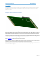
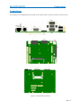
Daughter Board connector locations
Figure 1: Connector Locations
With an ETX daughter board, the main connections for Keyboard, Mouse, Video, IDE, USB etc are made via
the Host Board. On the ETX CN700 there are only two direct connections, both of which are SATA connectors.
Connection to the host board is with four Hirose plug connectors (part number FX8-100P-SV) which mate with
corresponding Hirose socket connectors (eg part number FX8-100S-SV). There are four mounting holes of
2.5mm diameter available for securing the daughter board to the host board
Refer to Appendix 1 for details of the connector pin descriptions
When installing or removing the daughter board onto the host board, ensure that all power has been removed,
including 5V stand- by if present and any external Lithium cell or RTC back-up battery.
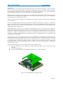
Before assembling the daughter board onto the host board, check that the mounting fittings are fitted to the host
board as shown below in Figure 2.
Page | 13
MAGNUM ETX
Installation
Figure 2: ensure mounting pillars are fitted to host board
The next action is to carefully align the connectors of the daughter board with those on the host board and
carefully press together.
Note: The Hirose connectors are offset from each other, so the daughter board will only fit on one orientation.
Trying to force the daughter baord in the wrong orientation may damage the connectors
Figure 3: Align daughter board connectors with the host board
If the memory module is not already fitted, then carefully fit the memory module onto the memory socket. The
socket is notched to indicate the orientation of the module
At this stage, the cooling solution should be applied. There are several different methods of cooling the Magnum
ETX
Page | 14
MAGNUM ETX
Installation
Cooling
Efficient cooling is essential for long and reliable operation of any electronic equipment. The VIA Eden/C7
CPU, the VIA CN700 Northbridge and VIA VT8237 Southbridge do get hot in normal operation, and in an
elevated ambient temperature will require additional cooling. Cooling requirements will vary with application,
desired operating temperature, CPU load, and memory size and board orientation.
Mounting the PCB vertically will aid natural convection and create a chimney effect. Passive heat sinks can be
used for the CPU, Northbridge and Southbridge. A fan, whilst not always desirable, will provide a high degree
of cooling even for a relatively slow airflow.
Further options that may be considered are sinking heat to the chassis or enclosure and in extreme situations the
use of a heat pipe.
The CPU is equipped with an onboard thermal diode for temperature monitoring. A thermistor is available to
monitor the temperature of critical and potential hot spots on the board. Temperatures can be monitored in the
BIOS Set-up. If you wish to monitor these temperatures from your application please contact the Blue Chip
Technology Technical Support team.
When designing an enclosure, bear in mind that the greater the volume of air that can flow through the
enclosure, the greater the cooling effect and the lower the temperature rise above the ambient air temperature.
However, the volume produced by any fan will vary with the pressure against which it has to work. The
resistance to airflow (the back-pressure on the fan) will depend upon the enclosure, the mounting and
restrictions. Therefore, when mounting and cabling the board, it is essential that the free circulation of the
cooling airflow is not impeded.
The calculation of airflow through an enclosure is not straightforward, and depends on many factors. The
method of meeting the cooling requirements will be specific for each system. Consequently, the system builder
is responsible for ensuring adequate cooling. However, interpreting airflow volumes is not intuitive. As an aid
to selecting suitable cooling, the following example is offered. A 60 mm axial fan (such as a Papst type
612NGH) blowing over the board can supply up to 46 m3/hour when unrestricted. Restrictions to the airflow
will reduce this volume.
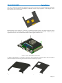
Blue Chip Technology offers several cooling solutions to help manage cooling:
Heat plate designed to allow contact with a larger cooling area such as direct contact with a metal
enclosure
A passive finned heatsink
An active solution based on the finned heatsink with a fan (12 m3/hour) attached
Figure 4: Position Heatsink above daughter board
Page | 15
MAGNUM ETX
Installation
The Active solution has thermal pads attached to the bosses on the base of the finned heatsink which make
direct contact with the surface of Northbridge, Southbridge and two voltage regulators on the daughter card to
help dissipate heat into the heatsink.
Figure 5: Heatsink bosses and thermal pads
Before fitting the active solution, it is necessary to spread some thermal grease to the surface of the boss which
will contact the CPU. Thermal grease is required as thermal pads provide less thermal conductivity than
required for the CPU. Note: the minimum amount of thermal grease should be used
Figure 6: secure the assembly using screws
To finish of the assembly, it is necessary to use screws to secure the active solution in place. This also protects
against the daughter board coming unseated from the host board during operation
Figure 6a: Passive cooler
Figure 6b: Heat Spreader
Page | 16
MAGNUM ETX
Installation
Stack Heights and Clearances
The Magnum ETX with an Active cooling solution stack heights are shown below.
Figure 7: MagnumX with Active Cooling Stack dimensions
Using the above example, the overall height from the inside base of an enclosure to the top edge of the screw
would be 54mm. As the fan draws air down from the top and pushes out through the sides, in this instance, there
is a requirement for at least 25mm clear space above the fan to ensure the fan operates efficiently. This could be
achieved two ways: firstly, a gap of 25mm between the top of the fan and the inside of the top cover, or
secondly, the cover could be just above the fan, with ventilation holes in the cover to allow air to flow freely
into the fan as shown in Figure 8 below.
Figure 8: Example of Cover close to top of fan
Page | 17
MAGNUM ETX
Connections
Connections
All connections to the Magnum ETX are made via the Carrier board. Connector positions are shown below
Figure 9: Front Connectors
Figure 10: Top Side Connectors
Figure 11: Bottom Side Connectors
Page | 18
MAGNUM ETX
Connector
J1
SW1
P7
P9
P11
P14
P16
Connections
Description
PCI VIO Select
Power + CF Selector
Parallel Port
IDE Connector
Fan Power
GPIO / Audio
LCD
Connector
J2
P1
P8
P10
P12
P15
P17
Description
Vcc LCD
USB Header
SM Bus
Power On/Reset
Power In
LCD
LCD
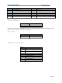
J1 PCI VIO Select
Connect
1-2
2-3
Output
5V
3V3
Note: If 5V is selected, some modern PCI cards which are 3V3 Signalling may not work. Conversely, if 3V3 is
selected, then older legacy 5V signalling cards may not work
J2 Vcc LCD
Connect
1-2
2-3
Output
5V
3V3
SW1 Power + CF Selector
SW1-1
On
Off
SW1-2
On
Off
SW1-3
On
Off
SW1-4
On
Off
Auto Power On
Follow P10 Power On/Off switch
CF Master
CF Slave
CF DMA Enabled
CF DMA Disabled
CF DMA Enabled
CF DMA Disabled
Page | 19
MAGNUM ETX
Connections
P1 Auxiliary USB
Pin
1
3
5
7
9
Description
+5V
USBP2USBP2+
Ground
NC
Pin
2
4
6
8
10
Description
+5V
USBP3USBP3+
Ground
NC
Pin
2
4
6
8
10
12
14
16
18
20
22
24
Assignment
P_AFD#
P_ERR#
P_INIT#
P_SLIN#
GND
GND
GND
GND
GND
GND
GND
GND
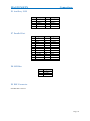
P7 Parallel Port
Pin
1
3
5
7
9
11
13
15
17
19
21
23
25
Assignment
PSTRB#
PPD0
PPD1
PPD2
PPD3
PPD4
PPD5
PPD6
PPD7
P_ACK#
P_BUSY
P_PE
P_SLCT
P8 SMI Bus
Pin
1
2
3
Assignment
GND
SM_SDA
SM_SCL
P9 IDE Connector
Standard IDE Connector
Page | 20
MAGNUM ETX
Connections
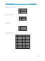
P10 Power On / Reset
Pin
1
2
3
4
Assignment
Reset
Ground
Power On / Off
Ground
P11 Fan Connector
Pin
1
2
3
Assignment
GND
12V
NC
P12 Power
Pin
1
2
3
4
Assignment
+12V
0V
0V
+5V
P14 GPIO Audio
Pin
1
3
5
7
9
11
13
15
17
19
21
23
25
27
29
Assignment
GPIO 0
GPIO 2
GPIO 4
GPIO 6
5V
GPIO 8
GPIO 10
GPIO 12
GPIO 14
GND
AGND
LineINR
AGND
LineoutR
AGND
Pin
2
4
6
8
10
12
14
16
18
20
22
24
26
28
30
Assignment
GPIO 1
GPIO 3
GPIO 5
GPIO 7
5V
GPIO 9
GPIO 11
GPIO 13
GPIO 15
GND
AGND
LineINL
AGND
LineoutL
MICIN
Page | 21
MAGNUM ETX
Connections
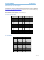
P15, P16 P17 LCD/LVDS Support
For LCD output there is a choice of 3 connector types. Connectors P16 and P17 provide quick connection for
pre-assembled 1 to 1 cables using type DF9-41P and DF9-31P connectors, such as produced by AXON Cables
(http://www.axon-cable.com/product/axon/fdc/fdc.htm). Connector P15 allows for custom cable design using
mating connector DF13-40DS.
NOTE 1: Only one connection is allowed
NOTE 2: Remember to set the appropriate Vcc for the Panel using J2
P15 LCD/LVDS DF13-40DP
Pin
1
3
5
7
9
11
13
15
17
19
21
23
25
27
29
31
33
35
37
39
LCD
INVPWR
GND
VCCLCD
VPOT
CB5
CB3
CB1
N/C
CG5
CG3
CG1
N/C
CR5
CR3
CR1
N/C
GND
CCLK
CDE
ENAB
LVDS
INVPWR
GND
VCCLCD
VPOT
ZC+
Z2+
Z1+
N/C
Z0+
N/C
YC+
N/C
Y2+
Y1+
Y0+
N/C
GND
CCLK
CDE
ENAB
Pin
2
4
6
8
10
12
14
16
18
20
22
24
26
28
30
32
34
36
38
40
LCD
INVPWR
GND
VCCLCD
GND
CB4
CB2
CB0
N/C
CG4
CG2
CG0
N/C
CR4
CR2
CR0
N/C
GND
CFLM
CLP
DIGON
LVDS
INVPWR
GND
VCCLCD
GND
ZCZ2Z1N/C
Z0N/C
YCN/C
Y2Y1Y0N/C
GND
CFLM
CLP
DIGON
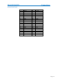
P17 LCD DF9-31S
Pin
1
3
5
7
9
11
13
15
17
19
21
23
25
27
29
31
Assignment
GND
CLP
GND
CR1
CR3
CR5
CG0
CG2
CG4
GND
CB1
CB3
CB5
CDE
VCCLCD
CB
Pin
2
4
6
8
10
12
14
16
18
20
22
24
26
28
30
Assignment
CCLK
CFLM
CR0
CR2
CR4
GND
CG1
CG3
CG5
CB0
CB2
CB4
GND
VCCLCD
CA
Page | 22
MAGNUM ETX
Connections
P16 LCD DF9-41S
Pin
1
3
5
7
9
11
13
15
17
19
21
23
25
27
29
31
33
35
37
39
41
Assignment
GND
GND
CFLM
GND
CR0
CR2
CR3
CR5
GND
CG0
CG2
CG3
CG5
GND
CB0
CB2
CB3
CB5
CDE
VCCLCD
CB
Pin
2
4
6
8
10
12
14
16
18
20
22
24
26
28
30
32
34
36
38
40
Assignment
CCLK
CLP
GND
GND
CR1
GND
CR4
GND
GND
CG1
GND
CG4
GND
GND
CB1
GND
CB4
GND
CA
VCCLCD
Page | 23
MAGNUM ETX
Software Configuration
System Software
Operating System Install
A DVD-ROM is supplied with each board, containing most common operating system drivers. Bear in mind
that suppliers continually update their drivers, so it is always a good idea to check on the Internet for later ones.
The following websites are good starting points:
www.viaarena.com
www.viatech.com
www.intel.com
For example for a fresh install of Windows XP operating system, drivers can be installed as follows
First install the Magnum ETX Chipset #1 drivers. This driver includes the graphics driver, and there are several
choices as to which particular driver to choose depending on your requirements. Refer to the readme file in the
Drivers\SBPC\ETXCN700\Chipset 1 sub directory for more information on the choices
Next install the Chipset 2 driver by executing the setup.exe file in the Drivers\SBPC\ETXCN700\Chipset 2
folder. This installs the necessary IDE/SATA/Raid driver for the VT8237 Southbridge device
For Audio driver, run the setup.exe file from the Drivers\SBPC\ETXCN700\Audio folder.
Lastly, for the LAN driver, use Device Manager and when prompted, point the install to the
Drivers\SBPC\ETXCN700\LAN\MS\X86 folder
Operating System API Functions
System Health Monitor
The support for the hardware monitor on the MAGNUM ETX processor board will be incorporated into the
unified system health monitor API library (SYSMON) and as such supports the following API calls…
DWORD BCTEnableHwMonitor(VOID);
DWORD BCTDisableHwMonitor(VOID);
DWORD BCTReadVoltage(BYTE bVoltageSource, DOUBLE *pdVoltageReading);
DWORD BCTReadTemp(BYTE bTempSource, DOUBLE *pdTempReading);
Watchdog / EEPROM
The support for the watchdog and EEPROM on the MAGNUM ETX processor board will be provided through
a board specific BCTAPI library and as such support the following API calls…
DWORD BCTOpen(WORD wDevice);
DWORD BCTClose(WORD wDevice);
DWORD BCTWatchdog(BYTE bWdgAction, BYTE bTimeout, BYTE bRange);
DWORD BCTWriteEeprom(WORD wOffset, BYTE bVal);
DWORD BCTReadEeprom(WORD wOffset, PBYTE pbVal);
DWORD BCTEraseEepromByte(WORD wOffset);
DWORD BCTEraseEeprom(VOID);
Page | 24
MAGNUM ETX
BIOS Setup
System BIOS
The MAGNUM ETX Single board PC uses the Phoenix BIOS, which has a built-in Setup program that allows
users to modify the basic system configuration. This type of information is stored in on-board flash for retention
when the power is turned off. Date and time information is in a battery-backed RAM (CMOS RAM) that retains
the information each time the power is turned off.
To enter the BIOS setup pages, press the <F2> key just after powering on the unit
If you want to temporarily change the BOOT order, for example to boot from a USB device, then during POST
or when the Splash screen is being displayed, press the <ESC> key to enter the BOOT selection Menu.
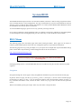
BIOS Menus
The following pages show the Menu pages found when entering the BIOS. These pages can be used as a
reference guide and descriptions of the main user configurable options are provided for information.
The following pages do not go into great depth, so if you require more in-depth data on particular BIOS settings
please contact Blue Chip Technology Technical Support staff via the web interface at
http://support.bluechiptechnology.co.uk/
Caution: Changing settings to the wrong values can result in an unreliable or
non working unit.
If changing settings, then it is recommended that these are recorded in a safe place for later reference by field
engineers
Navigation
Navigation through the various pages is fairly straightforward and hints are given at the bottom of each page.
In general, when on a page, use the Up (↑), Down (↓), Left (←) and right (→) arrows to move around the page,
use the Page Up <PgUp> or plus <+> key to increase the numeric value, the Page Down <PgDn> or minus <->
key to decrease the numeric value, and use the Enter <Enter> key to go to the sub menu for that particular
option.
When in a Sub Menu, pressing the escape <ESC> key will return to the parent menu
Page | 25
MAGNUM ETX
BIOS Setup
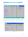
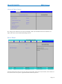
Main Menu
Picture B1
The Main menu allows the setting of Date and Time, as well as providing details of IDE devices fitted to the
unit.
Note: In the Boot menu shown later, SATA Channel 0 and 1 are equivalent to IDE 4 and IDE 5 respectively
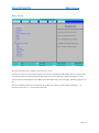
System Configuration Feature Sub Menu
Picture B2
Page | 26
MAGNUM ETX
BIOS Setup
In this sub menu, the important features are
Legacy USB – Enabled for USB Keyboards, Mice and FDD to be recognised during Boot
Quick Boot Mode – Enabled for faster boot process
Boot time Diagnostic Screen – Enabled for a summary of devices and their resources to eb shown after
POST and prior to OS load
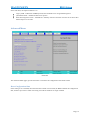
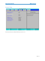
Advanced Menu
Picture B3
The Advanced Menu pages, provide the means to customise the configuration of the ETX CN700
Reset Configuration Data
If this setting is set to enabled, then when the ETX CN700 is next booted, the BIOS refreshes the configuration
data, and frees up resources which were being reserved for hardware no longer installed
Page | 27
MAGNUM ETX
BIOS Setup
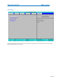
PnP Configuration Sub Menu
Picture B4
This sub menu allows the reservation of system resources for use with legacy ISA devices.
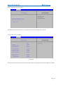
Chipset Devices Sub Menu
Picture B5
The Chipset sub menu allows for PATA, SATA, USB, Audio and LAN functionality to be enabled or disabled
Page | 28
MAGNUM ETX
BIOS Setup
Internal VGA Control Sub Menu
Picture B6
This sub menu allows the size of the frame buffer to be changes as well as selection of display type
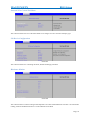
I/O Device Configuration
Picture B7
This sub menu allows for controlling the Serial, Parallel and Floppy interfaces
Hardware Monitor
Picture B8
This sub menu shows on board voltages and temperatures for CPU and motherboard. The CPU is an internal Die
reading, while the motherboard sensor is on the underside of the PCB
Page | 29
MAGNUM ETX
BIOS Setup
Advanced Chipset Control
Picture B9
Key settings in this submenu are the Allow ISA Bridge, which can be disabled as the host board does not
support ISA cards, and the Onboard Watchdog Timeout.
Power Menu
Picture B10
The Power Menu allows the user to set the state for power failure. Options are Off, Last State, and on. When set
to on, then as soon as AC power is applied the ETX CN700 will power on
Page | 30
MAGNUM ETX
BIOS Setup
Security Menu
Picture B11
The Security menu allows for BIOS and Boot passwords to be set
Page | 31
MAGNUM ETX
BIOS Setup
Boot Menu
Picture B12
The boot menu allows for a number of boot devices to be set
In total 8 boot devices can be selected. If there are 8 devices already listed and another device is required, then
one of the 8 needs to be removed from the Boot Order List by first selecting it, and then typing the “X” key
A device form the Excluded list can be added to the Boot Order list by first selecting it, and then typing the “X”
key.
Devices in the Boot Order List can be moved up and down the order by selecting them and hitting “+” to
increase up the order, or “-“ to move down the order
Page | 32
MAGNUM ETX
BIOS Setup
Exit Menu
Picture B13
As well as offering the means to exit with and without saving settings, this menu also allows for the System
BIOS Default Settings to be restored
Page | 33
MAGNUM ETX
Maintenance
Maintenance
The Magnum ETX Single Board PC should not require any regular maintenance. After a period of several years,
it may be necessary to replace the battery, if it cannot maintain the CMOS clock whilst the AC power is
disconnected. If an active cooling solution is fitted, then check on a regular basis that if dust builds up then it
does not impair the performance of the fan
Page | 34
MAGNUM ETX
History
Amendment History
Issue Level
1.0
Issue Date
25-03-09
Author
Amendment Details
TMCK
First release
Contact Details
Blue Chip Technology Ltd.
Chowley Oak
Tattenhall
Chester
CH3 9EX
U.K.
Telephone: +44 (0)1829 772000
Facsimile: +44 (0)1829 772001
www.bluechiptechnology.co.uk
Plasma PC Sales
[email protected]
Single Board Computer Sales
[email protected]
Rack mount/ Industrial PC Sales
[email protected]
Data and IO Sales
[email protected]
Technical Support
[email protected]
Page | 35