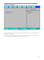
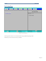
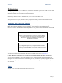
1
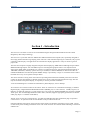
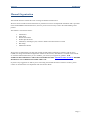
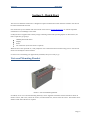
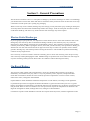
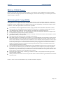
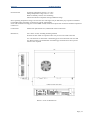
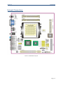
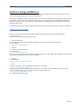
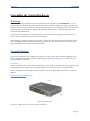
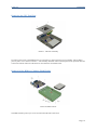
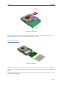
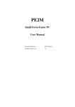
Vario L2 Small Form Factor PC User Guide Document Reference: Product User Guide Document Issue: 1.0 Vario L2 Table Of Contents Contents Section 1 - Introduction .......................................................................................................................................... 4 Copyright ............................................................................................................................................................ 5 Limitations of Liability ....................................................................................................................................... 5 Trademarks ......................................................................................................................................................... 5 Regulatory Statements ........................................................................................................................................ 6 Safety Warning for North America .................................................................................................................... 6 Manual Organisation .......................................................................................................................................... 7 Section 2 - Quick Start ............................................................................................................................................ 8 Universal Mounting Bracket ............................................................................................................................... 8 Section 3 - General Precautions .............................................................................................................................. 9 Electro-Static Discharges.................................................................................................................................... 9 On-Board Battery ............................................................................................................................................... 9 BIOS & CMOS Memory .................................................................................................................................. 10 Electromagnetic Compatibility ......................................................................................................................... 10 Section 4 – Product Summary .............................................................................................................................. 11 Specification ..................................................................................................................................................... 11 Section 5 - Installation .......................................................................................................................................... 13 External Connectors ......................................................................................................................................... 13 Internal Connections ......................................................................................................................................... 14 Jumper Locations .............................................................................................................................................. 15 CMOS Clear ................................................................................................................................................. 15 Software Setup and Drivers .................................................................................................................................. 16 Windows XP Professional ............................................................................................................................ 16 Upgrading the System Hardware .......................................................................................................................... 17 Warning ............................................................................................................................................................ 17 Upgrade Options ............................................................................................................................................... 17 Removing the System Cover ........................................................................................................................ 17 Removing the CPU Fan Plate ....................................................................................................................... 18 Removal of the HDD or Compact Flash Holder ........................................................................................... 18 PCI Device Removal .................................................................................................................................... 19 Memory and/or CPU Removal ..................................................................................................................... 20 Section 6 – BIOS SETUP ..................................................................................................................................... 21 BIOS Setup ........................................................................................................................................................... 21 Main Setup page ............................................................................................................................................... 22 Security ......................................................................................................................................................... 22 Memory ........................................................................................................................................................ 23 Page | 2 Vario L2 Table Of Contents Advanced Setup Page ....................................................................................................................................... 24 Hard Disk Boot Priority ................................................................................................................................ 25 Advanced BIOS Features ............................................................................................................................. 25 Advanced Chipset Features .......................................................................................................................... 27 PnP/PCI Configurations................................................................................................................................ 29 Frequency/Voltage Control .......................................................................................................................... 29 Integrated Peripherals Page .............................................................................................................................. 30 South On Chip IDE Device .......................................................................................................................... 30 South On Chip PCI ....................................................................................................................................... 31 On Board I/O Chip Setup ............................................................................................................................. 31 Power Setup Page ............................................................................................................................................. 32 Hardware Monitor Setup Page .......................................................................................................................... 34 Defaults Setting Page ........................................................................................................................................ 35 Exit Setup Page ................................................................................................................................................. 36 Maintenance ......................................................................................................................................................... 37 Replacing the Processor Battery ....................................................................................................................... 37 Fuses ................................................................................................................................................................. 37 Amendment History ............................................................................................................................................. 38 Page | 3 Vario L2 Introduction Picture 1: Vario L2 Section 1 - Introduction The Vario L2 is the latest in a line of successful Plasma Engines designed and manufactured in the United Kingdom by Blue Chip Technology. The Vario L2 is a powerful slim-line AMD Socket AM2 based Personal Computer (PC) specifically designed to drive large plasma and other large display panels. The unit is self-contained requiring as a minimum, only a power connection and a display. The applications are not limited to display applications: it may be used as a general purpose PC. The basic unit comprises a highly integrated computer board employing AMD 690G Northbridge chipset and the SB600 Southbridge chipset with ATI Radeon Xpress 1250 integrated graphics feature. The computer board supports the AMD Athlon 64 X2 Dual-core / Athlon 64 / Sempron Processor with Front Side Bus frequencies of 1000 MHz (2000 MT/s). Memory options allow up to of 2GB (2 x 1GB SO-DIMMs) of ultra fast non-ECC & unbuffered DDR2 667/533/400 200-pin SO-DIMM. Storage is provided by a single 3½-inch Serial ATA II 3Gb/s hard disk drive or by use of optional Compact Flash. The unit is housed in a strong sheet-steel enclosure providing both mechanical and EMC protection. Fans draw cooling air into the unit and direct it through the chassis to ensure a wide operating temperature range. The unit may be mounted on the plasma display, or separately to suit the particular installation A universal Mounting kit is available for attachment to plasma displays, wall or desktops. All connectors are on the Front face of the chassis. There are connectors for a standard VGA display, a standard Digital Display, a High Definition Multimedia Interface (HDMI) port, TV-Out connector, 4 USB (2.0) ports, an Ethernet (10/100/1Gb) LAN port, a 1394a Firewire port, one serial port, SPDIF IN/SPDIF Out connectors and HD Audio ports. The on-board High Definition Audio codec (ALC883) supports high quality performance 8-channel audio play (Super 7.1 Channel Audio Effect) The DC power jack is also on the front face. An OD5.5mm and ID2.5mm short termination plug is required to connect to this. An optional AC/DC Power Module can be provided with the unit. External indicators and controls on the front face of the chassis are limited to a hard drive activity LED, a power on LED and a power/standby push-button switch. The LAN connector also includes LEDs indicating a connection and data rate. Page | 4 Vario L2 Introduction Copyright All rights reserved. No part of this publication may be reproduced, stored in any retrieval system, or transmitted, in any form or by any means, electronic, mechanical, photocopied, recorded or otherwise, without the prior permission, in writing, from the publisher. For permission in the UK please contact Blue Chip Technology. Information offered in this manual is believed to be correct at the time of printing. Blue Chip Technology accepts no responsibility for any inaccuracies. The information contained herein is subject to change without notice. There are no express or implied licences granted herein to any intellectual property rights of Blue Chip Technology Ltd. Limitations of Liability In no event shall Blue Chip Technology be held liable for any loss, expenses or damages of any kind whatsoever, whether direct, indirect, incidental or consequential, arising from the design or use of this product or the support materials supplied with this product. If this product proves to be defective, Blue Chip Technology is only obliged to replace or refund the purchase price at Blue Chip Technology's discretion according to their Terms and Conditions of Sale. Trademarks All trademarks and registered names acknowledged. IBM, PC, AT and PS/2 are trademarks of International Business Machines Corporation (IBM). AMD is a registered trademark of Advanced Micro Devices Inc. All Athlon processors are registered trademarks of Advanced Micro Devices Inc. GeForce and nForce are registered trademarks of the NVIDIA Corporation SoundMAX is a registered trademark of Advanced Micro Devices Inc. AMI is a registered trademark of American Megatrends Inc. MSDOS and WINDOWS are registered trademarks of the Microsoft Corporation. Page | 5 Vario L2 Introduction Regulatory Statements CE This product meets the essential protection requirements of the European EMC Directive (2004/108/EC) and its amending Directives, and the Low Voltage Directive (2006/95/EC), and is eligible to bear the CE mark. Warning This is a Class A product. In a domestic environment this product may cause radio interference in which case the user may be required to take adequate measures. FCC NOTE: This equipment has been tested and found to comply with the limits for a Class A digital device, pursuant to Part 15 of the FCC Rules. These limits are designed to provide reasonable protection against harmful interference when the equipment is operated in a commercial environment. This equipment generates, uses, and can radiate radio frequency energy and if not installed and used in accordance with the instruction manual, may cause harmful interference to radio communications. Operation of this equipment in a residential area is likely to cause harmful interference in which case the user will be required to correct the interference at his own expense. WARNING: Changes or modifications not expressly approved by the manufacturer could void the user's authority to operate the equipment. Safety Warning for North America If the power lead (cord) is not supplied with the computer, select a power lead according to your local electrical regulations. In the USA use a 'UL listed' lead. In Canada use a CSA approved or 'cUL listed' lead. Si le cordon secteur n'est pas livré avec l'ordinateur, utiliser un cordon secteur en accord avec votre code electrique nationale. En l'Etat Unis utiliser un cordon secteur 'UL listed'. En Canada utiliser un cordon secteur certifié CSA, ou 'cUL listed'. Page | 6 Vario L2 Introduction Manual Organisation This manual describes in detail the Vario L2 range of Small Form-Factor PCs. We have tried to include as much information as possible but we have not duplicated information that is provided in the standard IBM Technical References, unless it proved to be necessary to aid in the understanding of the product. The manual is sectioned as follows: 1. 2. 3. 4. 5. 6. 7. Introduction Quick Start General Precautions Product Specifications Installation, including Layout, connector details and what software to install Bios Setup Maintenance details We strongly recommend that you study this manual carefully before attempting to interface with the Vario L2(SBC) or change the standard configurations. Whilst all the necessary information is available in this manual we would recommend that unless you are confident, you contact your supplier for guidance. IT IS PARTICULARLY IMPORTANT THAT YOU READ THE SECTION 'GENERAL PRECAUTIONS' BEFORE HANDLING ANY COMPONENTS INSIDE THE UNIT. If you have any suggestions or find any errors concerning this manual and want to inform us of these, please contact our Technical Services department with the relevant details. Page | 7 Vario L2 Quick Start Section 2 - Quick Start The Vario L2 Small Form-Factor PC is designed to require minimal intervention from the customer once the OS has been installed and activated. First ensure that you are familiar with the contents of the section "General Precautions". It contains important information to avoid damage to the board. Usually the unit is supplied with a factory image containing a Microsoft Operating System. In this instance, all that is required to get going is USB Keyboard and mouse Display Power Lan connection (if OS activation is required) When the unit is first powered on, it will prompt the user to follow the Microsoft mini setup process. All relevant drivers will already have been installed. It’s then a case of installing your application(s) and data, and you’re ready to go. Universal Mounting Bracket Picture 2: Universal Mounting Bracket If ordered, one or two Universal Mounting bracket(s) can be supplied. The bracket will be attached as shown in Picture 2 above, and to use, remove the screws, turn the bracket 180˚, then re-insert the screws. The bracket can be fitted to either end of the unit as required. Page | 8 Vario L2 General Precautions Section 3 - General Precautions The electronics inside the Vario L2 is susceptible to damage by electrostatic discharges. In order to avoid damage, you should work at an anti-static bench and observe normal anti-static precautions. Wear an anti-static wrist strap connected to an earth point before opening any packaging. Where a wrist strap is not available, discharge any static charge you may have built-up by touching an earth point. Avoid any further movement that could build up another static charge. Touch an earth point from time to time to avoid further build-up, and remove any items from their anti-static bags only when required Electro-Static Discharges If you are going to open up the unit, it is important to realise that the devices on the cards within this unit can be damaged by static electricity. Bear in mind that the damage caused by static electricity may vary from total destruction to partial damage, which may not be immediately obvious. This could have an effect on the product's reliability and warranty. Before opening the chassis, ensure that you take necessary static precautions. Ideally you should work at an anti-static bench and wear an approved wrist strap or if that is not possible, touch a suitable ground to discharge any static build up before touching the electronics. This should be repeated if the handling continues for any length of time. If it is necessary to remove a board or electronic assembly, place it into an anti-static bag. This will prevent any static electricity build up damaging the board. Metallised bags are preferred. Do not use black anti-static bags for any item containing a battery because these tend to be conductive and will discharge the battery. On-Board Battery The processor board is fitted with a Lithium battery. Great care should be taken with this type of battery. If the battery is mistreated in any way there is a very real possibility of fire, explosion, and personal harm. Under NO circumstances should it be short-circuited, exposed to temperatures in excess of 100C or burnt, immersed in water, recharged or disassembled. Expired batteries remain hazardous and must be disposed of in a safe manner, according to local regulations. Le panneau de processeur est équipé d’une batterie de lithium. Le grand soin devrait être pris avec ce type de batterie. Si la batterie est mistreated il y a de dans de toute façon un possibility très vrai du feu, d’expolosion et de mal personnel. Dans au cunes circonstances il est sous peu circuité, exposé aux températures au dessus de 100 degrés de centrigrade ou brûlé, immergé dans l’eau, rechargée ou dissassambled. Les batteries expirées restent dazaedous et doivent être reejetées d’une façon sûre, selon des règlements locaux. . Page | 9 Vario L2 General Precautions BIOS & CMOS Memory Please be aware that with personal computer products, it is possible to create configurations within the CMOS memory that make booting impossible. If this should happen, clear the CMOS settings; (see the description of the Jumper Settings for details). Electromagnetic Compatibility This product meets the requirements of the European EMC Directive and its amending Directives, and the Low Voltage Directive. It is eligible to bear the CE mark. However, because the unit can be installed in a wide variety of situations, certain conditions have to be applied to ensure that the compatibility is maintained. Subject to those conditions, it meets the requirements for an ITE Class A product. The VARIO L2 must be supplied with a clean AC supply, and the chassis should be connected to a sound earth (ground). As a minimum the power cord must be connected to an earthed (grounded) supply or outlet. Any additional items installed or used with the Vario L2 should carry appropriate approvals When installing additional items, any recommendations made by the component manufacturer/supplier must be complied with regarding earthing and the installation. The metal back plate of any expansion card must be securely screwed to the chassis of the computer to ensure good metal-to-metal (i.e. earth) contact. All connector bodies must be securely connected to the enclosure. Most EMC problems are attributable to the cabling. It is recommended that screened cabling is used wherever possible, and that the screen of the cable connects to the metal end bracket of the board or the enclosure and hence to earth. Round, screened cables with a braided wire screen should be used in preference to those with a foil screen and drain wire. Use metal connector shells that connect around the full circumference of the cable screen: they are far superior to those that earth the screen by a simple “pig-tail” connection. This method attempts to extend the enclosure around the connecting cables, thereby trying to surround the whole of the internal equipment and external cabling. The keyboard and mouse will play an important part in the compatibility of the processor card since they are ports into the board. Similarly, they will affect the compatibility of the complete system. Fully compatible peripherals must be used otherwise the complete system could be degraded. They may radiate or behave as if keys/buttons are pressed when subject to interference. Under these circumstances it may be beneficial to add a ferrite clamp on the leads as close as possible to the connector. USB cables must be high quality screened types suitable for USB 2.0, and peripherals must be approved to equivalent EMC standards. Where possible ensure that the screens of any external cables are also bonded to a good RF earth at the remote end of the cable. Failure to observe these recommendations may invalidate the EMC compliance. Page | 10 Vario L2 Product Summary Section 4 – Product Summary Specification CPU: AMD Athlon 64; AMD Athlon 64 X2 Chipset: Northbridge: AMD 690G SouthBridge: ATI SB600 I/O Controller – ITE IT8712F IEEE 1394 – VIA VT6307 HD Audio Codec – Realtek ALC883 Gbit LAN – Marvel 88E8056 Graphics – ATI Radeon Xpress 1250 Memory: DDR2 200 pin SO-DIMM (2 sockets) 2Gb Maximum capacity Supports non-ECC& unbuffered DDR2 667/533/400 SO-DIMMs Expansion: One PCI slot – rev 2.3 compliant Note: Due to power supply constraints, check with Blue Chip Technology Support for details of supported cards Storage: SATA HDD Compact Flash Choice configurable at time of order Connectors; One IEEE 1394 port One Gbit LAN Port Supports 10/100/1000 Mbps Ethernet LAN One coaxial S/PDIF In One coaxial S/PDIF Out One RCA S/PDIF Out One TV_OUT connector One VGA (D-Sub) connector One HDMI port HD Audio port 8/6/4/2 channel playback capability Jack sensing and re-tasking support Dolby Digital Live Technology Four USB 2.0 ports One power jack Hardware monitor: CPU/Chassis Fan Speed CPU and System Temperatures System Voltages Indicators: Power On LED, Hard Drive Activity LED, LAN Speed and Activity LED’s Control: Power standby pushbutton switch Power: 120W PICO 12V DC Internal Power Supply External power via OD5.5mm, ID2.5mm short Jack Socket Note: the plug should be no longer than 10mm long to avoid damaging the socket housing Page | 11 Vario L2 Environmental: Product Summary Operating Temperature range 0˚C to +40˚C Storage Temperature range -20˚C to +70˚C Relative humidity 10-85% non-condensing Shock and vibration compatible with light industrial usage Note: Operating Temperature range is for the basic unit. This figure may be affected by any expansion card fitted. Contact Blue Chip Technology to discuss any specific requirements. Units with mechanical moving parts such as HDD’s fitted, should not be bpowered on whent he ambient temperature is below 5˚C Construction: Painted zinc-plated sheet steel, welded and riveted construction Dimensions; 300 x 200 x 57 mm, excluding mounting brackets Note that at least 60mm is required to allow easy access to the cable connectors Air vents must not be obstructed. A minimum gap of 25 mm between side vents and any adjacent items is recommended. A minimum gap of 45mm above the top of the chassis is also required Picture 3: Vario L2 Dimensions Page | 12 Vario L2 Installation Section 5 - Installation External Connectors On / Off Picture 4 connectors The above picture shows the connectors on the front of the Vario L2 unit. Usually, to operate the unit, the following connections will be required Power - Jack Socket Keyboard – USB x 1 Mouse – USB x 1 Display – VGA or DVI or HDMI Network – RG45 Shielded Socket Page | 13 Vario L2 Installation Internal Connections Picture 5: Motherboard Layout Page | 14 Vario L2 Installation Jumper Locations The processor board used in the VARIO ELITE PC is largely free of selection jumpers. Most settings are controlled from the BIOS, and stored in the CMOS memory. Only the following jumpers are significant. CMOS Clear The CMOS clear jumper JP1 is located at the end of the PCI slot. Position Function 1-2 2-3 Normal Operation Clears CMOS This is used when the CMOS settings have become corrupt or if you have forgotten your password. Clear CMOS resets the BIOS to its default conditions Page | 15 Vario L2 Installation Software Setup and Drivers Your Vario L2 Small Form-Factor PC may have been supplied complete with a software operating system, in which case the appropriate drivers will have been loaded. If it has been supplied without an operating system, one must be loaded following the instructions supplied with the software. It is then necessary to add driver programs for the specific hardware of the motherboard and any additional expansion cards. The manner in which the drivers are loaded will vary depending upon the actual operating system used The following section gives details of where to find the necessary drivers and the order in which to install them Windows XP Professional Drivers for Vario L2 unit can be found on the Support CD supplied with unit in the following folder .. \Drivers\Vario L2 Drivers can be installed int he following order 1 – Dot Net framework This is required in order to fully install the Graphics driver, which is part of the chipset driver To install this run .. \Drivers\Vario L2\dotnetfx.exe 2 – Chipset This includes the graphics driver To install this run .. \Drivers\Vario L2\chipset.exe This driver includes games links as well as registration forms, so it is advisable when prompted to select Custom Install and install only the drivers which are required 3 – Network To install this run ..\Drivers\Vario L2\LAN\SetupCPwin.exe 4 - Audio There are two stages to this, first install the Audio driver by running ..\Drivers\Vario L2\Audio\setup.exe During this install, the New Hardware Detected windows will open in the background. Ignore these, as the driver will automatically take care of these. After the required reboot, run ..\Drivers\Vario L2\HDAudio\setup.exe This will finalise the audio setup Page | 16 Vario L2 Installation Upgrading the System Hardware Warning Before attempting any upgrade to the Vario L2 computer, please read the section "Precautions". For your personal safety it is important that you ensure that the unit is switched off, and the DC supply is disconnected. Remember that the unit incorporates an ATX-type of power supply unit. Switching the power off using the front panel switch does not isolate the DC supply, and under these conditions the +5V DC standby power is still connected to the motherboard. For the safety of the equipment, it is important that you observe electrostatic discharge precautions. Do not remove new items from their anti-static bags until necessary. When making any internal changes to the computer, it is imperative that the internal cables follow the original routes and additional cables are installed as described. Failure to observe this requirement could restrict the airflow through the unit and cause overheating problems. Upgrade Options The user may upgrade the unit by adding more memory or a faster CPU to the unit. Before upgrading, please check with Blue Chip Technical support by emailing [email protected] to find out if your proposed upgrade is supported. PCI Options The unit incorporates only a 120W Pico Power Supply. As such, great care should be used if trying to select and fit a PCI adapter card, as there may not be enough system power available to allow it to operate reliably Please contact Blue Chip Technology Technical support at the above email address to discuss your proposed addition. Removing the System Cover Picture 6: System Cover The cover is held in place by 5 screws as shown in Picture 6 Page | 17 Vario L2 Installation Removing the CPU Fan Plate Picture 7: CPU Fan Assembly In order to gain access to the Motherboard, it is necessary to remove the Fan Cover Assembly. This is held in place by the 3 screws shown in Picture 7. The assembly should be removed and replaced in an upwards direction to allow the smooth removal of the PCI riser card from the on-board PCI slot. Removal of the HDD or Compact Flash Holder Picture 8: HDD removal The HDD is held in place by 4 screws accessed from the base of the Unit Page | 18 Vario L2 Installation Picture 9: Compact Flash The compact Flash Adapter is mounted onto a plate which utilises the same mounting holes and screws as the HDD. Consequently, only one of these items can be fitted at any one time PCI Device Removal Picture 10: PCI Devices Before PCI Devices (shown as A in Picture 10 above) can be removed, it is necessary to remove screw B and Insulator C. The Insulator is to prevent any pins or components on the rear of the PCI card from shorting against the LID. Note: PCI card options are only available at time of order. If ordered without PCI expansion, the Riser card and insulator will not be supplied Page | 19 Vario L2 Installation Memory and/or CPU Removal Picture 11: Memory and CPU Access to the Memory slots is gained as soon as the Fan Assembly cover is removed. To access the CPU, the Heatsink must first be removed, by unscrewing the 4 screws marked D in Picture 11 above. Page | 20 Vario L2 BIOS Setup Section 6 – BIOS SETUP BIOS Setup To enter the BIOS setup Pages, press <DEL> during POST. Navigation through the different menus is via the Arrow Keys as explained in the bottom panel. Up/Down arrows navigate through the items in a particular menu, and Left/Right arrows navigate between Menu’s. If entering a sub-menu, <esc> will take you back up to the previous level. Pressing <F6> at any time sets the BIOS to its Default settings, and pressing <F10> at any time will prompt to Save the settings prior to exit. The Vario L2 will then reboot and load the desired settings. Figure A: Navigation Keys Warning: Selecting the wrong settings may cause system instability. If this occurs, enter BIOS and select Default Settings The following section provides the options available under the different menu’s. Page | 21 Vario L2 BIOS Setup Main Setup page Figure B: Main Setup Page Figure A shows the options available under the Main section with their default values. IDE Channel Options: Channel 0 refers to Parallel ATA, and Channel 2 and 3 refer to Serial ATA. By selecting the particular channel, default Automatic recognition can be turned off and settings can be manually entered. Halt On This feature selects the situation in which you want the BIOS to stop the POST process and notify of errors Options are: All errors; No errors; All, but keyboard; All, but diskette; All, but dikette.Keyboard Security Figure C: Security sub-menu Page | 22 Vario L2 BIOS Setup The Security sub menu allows the user to set/disable passwords for entering the BIOS and for booting the unit Memory This area shows the amount of conventional memory detected during boot, the amount of extended memory detected and the total memory available in the system Page | 23 Vario L2 BIOS Setup Advanced Setup Page Figure D: Advanced Menu The following options do not have a sub-menu First Boot Device: Set to HDD Second Boot Device: Set to either removable or CDROM Third Boot Device: Set to either removable or CDROM Boot Other Device: Set to Enabled if you want the BIOS to search for other boot devices if it can’t find a boot device on the first three devices. Otherwise set to Disabled The following options have a sub-menu for setup Hard Disk Boot Priority Advanced BIOS Features Advanced Chipset Features PnP/PCI Configuration Frequency/Voltage Control Page | 24 Vario L2 BIOS Setup Hard Disk Boot Priority This section allows the user to pre set the boot order if more than one HDD is present. Some USB Flash devices are regarded as “HDD’s” by the BIOS. TIP: During POST, if the <ESC> key is pressed, the BIOS automatically shows a temporary BOOT menu. If there are two “HDD” devices present in the unit, then by selecting “HDD” at the menu, the user will be presented with a choice of which “HDD” to boot to. Using this method, there is no need to enter BIOS to change the normal boot order. Advanced BIOS Features Figure E: Advanced BIOS features Virus Warning – Options Disabled (Default), Enabled This option allows you to choose the Virus warning feature for the HDD boot sector protection. If tis functi is enabled and a program attempts to write data into this area, BIOS will display a warning message on the screen and sound an audio alarm (beep). CPU Internal Cache – Options Enabled (default), Disabled Makes CPU internal cache active or inactive. System performance may degrade if you disable this item Page | 25 Vario L2 BIOS Setup External Cache – Options Enabled (default) Disabled This option allows you to enable or disable “level 2” secondary cache on the CPU to enhance performance Quick Power on Self Test – Options Enabled (default) Disabled If enabled, this allows the system to skip certain tests while booting. This speeds up the boot process Swap floppy drive – Options Disabled (default) Enabled No floppy drive fitted so leave this set to Disabled Boot Up NumLock Status - Options On (default) Off This setting determines the initial power-on state of Numpad keys. On, and they are set to number keys, Off and they are se to arrow keys Typematic Rate Setting – Option Disabled (default) Enabled This setting determines the keystroke repeat rate for the controller. When enabled, the user can choose faster response when keys are held down MPS Version Control for OS – Options 1.4 (default) 1.1 Version 1.4 is used for Windows 2000, Windows XP and later. Version 1.1 is used for older OS’s such as Windows NT OS Select for DRAM >64MB – Options Non-OS2 (default) OS2 Leave at default, OS/2 is not supported HDD S.M.A.R.T. Capability – Options Disabled (default) Enabled The Self Monitoring analysis and Reporting Technology (SMART) enables a PC to attempt to predict the possible failure of storage drives Page | 26 Vario L2 BIOS Setup Advanced Chipset Features Figure F: Advanced Chipset features DRAM Configuration Figure G: This sub menu offers the user the ability to change the memory clock and timing values. Note: users should exercise caution when making changes here, as it may result in the system becoming unstable. If problems occur the user may have to use the Clear CMOS jumper to reset the BIOS to a stable condition HT Link Control Figure H: This sub menu allows the user to change the HT Link width and frequency Page | 27 Vario L2 BIOS Setup IGX Configuration Figure I This sub menu allows the user to enable or disable UMA mode, set the UMA frame buffer size, set the TV Out standard and set the Video Display Device Video Display device options are: Auto (default), CRT Only, LCD Only, DFP Only, TV Only, CRT Force Other Auto, TV force Other Auto, CRT Force TV force TV Standard options are; NTSC (default0, PAL, PAL-M, PAL-60, NTSC-JAP, PAL-CN, PAL-N, SCART_RGB Memory Hole – Option Disabled (defaut) Enabled When enabled you can reserve an area of system memory for ISA adapter ROM. When this area is reserved it cannot be cached System BIOS Cacheable: Options Disabled (default) Enabled When enabled, accesses to system BIOS ROM at F0000H-FFFFFH are cached Page | 28 Vario L2 BIOS Setup PnP/PCI Configurations Figure J: PnP/PCI Configuration PCI/VGA Palette Snoop – Options Disabled (default) Enabled This is for graphics controllers which are not VGA compatible to allow them to take the output from a VGA controller and map it to their display as a way to provide boot information and VGA compatibility PCI Latency Timer (CLK) = Options 64 (defaul0t, 0-255 PCI latency timers are a mechanism for PCI bus-mastering devices to share the PCI bus fairly. The higher the number, the longer the device holds onto ownership Maximum Payload Size The PCI-Express maximum payload size can be set. The default is 4096, and the options are 128, 256, 512, 1024 and 2048 Frequency/Voltage Control Figure K: frequency / voltage control If the CPU has not been locked, then adjustments to these values can adjust the frequency and voltage of the cpu. Page | 29 Vario L2 BIOS Setup Integrated Peripherals Page Figure L: Peripheral Setup South On Chip IDE Device Figure M: South On Chip Page | 30 Vario L2 BIOS Setup The Vario L2 has limited expansion capability, and so the settings in the South On Chip IDE sub menu should be left at default South On Chip PCI Figure N: South On Chip PCI ATI Azalia Audio – Options Auto (default) Disabled This options allows you to turn of the on board Audio USB Functions Vario L2 does not have a PS/2 Keyboard or Mouse port, and therefore USB must be enabled if a USB Keyboard or Mouse is to be used. It is recommended that these settings be left at their default values On Board I/O Chip Setup Figure O: I/O Setup Onboard Serial Port 1 – Options 3F8/IRQ4 (default), Disabled, 2F8/IRQ3, 3E8/IRQ4, 2E8/IRQ3 This allows you to set the serial address and corresponding interrupt, or even disable the port if required Page | 31 Vario L2 BIOS Setup Power Setup Page Figure P: Power menu This Menu section sets up the unit so that it can automatically go into power saving modes, thus utilizing energy saving features, as well as providing power-up, power-down options ACPI Suspend Type ACPI Operating System options are S1 (POS) Default S3 (STR) S1 & S3 Power on Suspend Suspend to RAM POS & STR C2 Disable/Enable This controls whether ACPI C2 state is used Power Management Option Options for this are User Defined, Minimum Power Saving, and Maximum Power Saving HDD Power Down – Options Disabled (default), Enabled When Enabled, this allows the HDD to power down after a configurable period of system inactivity time Page | 32 Vario L2 BIOS Setup Video Off Option – Options Suspend →Off (default), Always On This section controls whether the Video goes into power states or not Video Off Method This setting determines the manner in which the video is turned off V/H Sync + Blank (default) Blank Screen DPMS Support turns off vertical and horizontal syncs and writes blanks to the video buffer writes blanks to the video buffer uses display power management signalling Modem Use IRQ This option sets the IRQ line the modem will use. Default is 3 Soft-Off by PWRBTN When the system is hung, this setting determines the response to pressing the power button. Options are Instant-OFF (default) or Delay 4 Sec PCI PME Wake UP – Options Disabled (default), Enabled This option when enabled will allow the system to wake up with any onboard LAN activity ACPI XSDT Table The XSDT refers to the Extended System Description Table. This should only be used for 64bit operating systems HPET Support – Options Disabled (default), Enabled The High Precision Event Timer (HPET) is capable of improving system performances. The HPET can produce periodic interrupts at a much higher resolution than the RTC and is often used to synchronize multimedia streams, providing smooth playback and reducing the need to use other timestamp calculations such as an x86 CPU's RDTSC instruction. This can only be used with later OS’s such as Windows Vista and later versions of Linux PWRON after PWR-Fail Determines whether the system will boot automatically after power fail or not Off (default) Former-State On System will remain off System will return to its state prior to power fail. If off, will remain off, if On will turn on System will turn on. If the unit was off before, it will now turn on RTC Wake Up - Options Disabled (default), Enabled When enabled, you can set the date and time at which the RTC will waken the system from Suspend mode AMD K8 Cool & Quiet Control – Options Disabled (default), Auto When set to Auto the system will automatically control the CPU voltage and frequency depending on the system loading Page | 33 Vario L2 BIOS Setup Hardware Monitor Setup Page Figure Q: Hardware Monitor This page shows the measured system voltages and temperatures. Smart Fan Control – Options Disabled (default), Enabled When enabled, this allows the system to monitor the CPU temperature and intelligently adjust the CPUFAN speed to maintain a safe temperature for the CPU. The benefit of this that at low temperatures and low activity, the noise level for the fan is reduced Page | 34 Vario L2 BIOS Setup Defaults Setting Page Figure R: Defaults As well as allowing the System Setting to be restored to their default settings, the user can save the CMOS settings to a file and then restore them again. This is useful when configuring multiple systems with customised settings. You can set the settings on one system, verify they work successfully, save them, and then restore them onto all your other units. Page | 35 Vario L2 BIOS Setup Exit Setup Page Figure S: Exit Setup menu The Exit page allows the user to exit with and without saving any BIOS setting changes made. Alternatively, the user can use the <F10> key command Page | 36 Vario L2 Maintenance Maintenance On a regular basis the inside of the VARIO L2 unit should be cleaned out to prevent dust build up which could eventually clog the fans and prevent efficient operation. If the optional Fan Filter is fitted, then this should be checked on a regular basis and cleaned or replaced as required. Generally the enclosure design and the wiring layout will ensure that the cooling is stable. However, bear in mind that any modifications to the installation may cause a restriction of the air vents. After a period of several years, it may be necessary to replace the battery on the processor board, if it cannot maintain the CMOS memory whilst the AC power is disconnected. Replacing the Processor Battery The processor board includes a small 3V lithium battery (type CR-2032) to retain the BIOS settings in the CMOS memory. Before attempting to replace the battery, please read the precautions detailed in the introductory section. Remember that even discharged batteries can present a real personnel hazard if mistreated. CAUTION Danger of explosion if battery is incorrectly replaced. Replace only with the same or equivalent type recommended by the manufacturer. Dispose of used batteries according to the manufacturer's instruction. ATTENTION Il y a danger d'explosion s'il y a remplacement incorrect de la batterie. Remplacer uniquement avec une batterie du même type ou d'un type recommandé par le constructeur. Mettre au rébut les batteries usagées conformément aus instructions du fabricant. The battery is located on the motherboard in the bottom right hand corner as shown in Picture 5. Do NOT under any circumstances try to remove the battery with metallic tools (pliers, tweezers etc.). They will short out the battery with possible disastrous results. Replace the battery by one of the same type, ensuring that it is fitted with the positive terminal facing the CPU, and that the clip is fully engaged. When the battery has been replaced, the BIOS settings will revert to their default settings. Reset them as necessary to suit your application. Fuses There are no user-serviceable or replaceable fuses within the unit. Page | 37 Vario L2 History Amendment History Issue Level Issue Date Author Amendment Details 1.0 20-12-2007 T Mck First Release Contact Details Blue Chip Technology Ltd. Chowley Oak Tattenhall Chester CH3 9EX U.K. Telephone: +44 (0)1829 772000 Facsimile: +44 (0)1829 772001 www.bluechiptechnology.co.uk Plasma PC Sales [email protected] Single Board Computer Sales [email protected] Rack mount PC Sales [email protected] Data and IO Sales [email protected] Technical Support [email protected] Page | 38