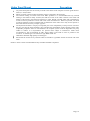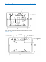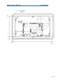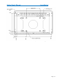
1
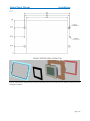
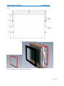
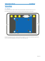
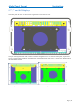
Alpha Touch Computer
Panel Mount PC
User Guide
Document Reference: User Guide
Document Issue: 1.1
Page | 1
Alpha Panel Mount
Table Of Contents
Contents
Copyright ............................................................................................................................................................ 4
Limitations of Liability ....................................................................................................................................... 4
Trademarks ......................................................................................................................................................... 4
Regulatory Statements ........................................................................................................................................ 5
Safety Warning for North America .................................................................................................................... 5
Manual Organisation .............................................................................................................................................. 6
Introduction ............................................................................................................................................................ 7
Functional Overview .......................................................................................................................................... 8
Specification ....................................................................................................................................................... 8
General Precautions ................................................................................................................................................ 9
Electro-Static Discharges.................................................................................................................................... 9
On-Board Battery ............................................................................................................................................... 9
Electromagnetic Compatibility ........................................................................................................................... 9
Mechanical Specifications .................................................................................................................................... 11
Outline Dimensions .......................................................................................................................................... 11
4.3” Display Open Frame ................................................................................................................................. 11
4.3” Closed Frame ............................................................................................................................................ 12
7” Display Open Frame .................................................................................................................................... 14
7” Display Closed Frame .................................................................................................................................. 16
5.7” Display Open Frame ................................................................................................................................. 18
5.7” Closed Frame ............................................................................................................................................ 20
8.0” Open Frame .............................................................................................................................................. 22
8.0 Closed Frame .............................................................................................................................................. 24
Connector Locations ............................................................................................................................................. 26
4.3” Display ...................................................................................................................................................... 26
7” Display ......................................................................................................................................................... 26
5.7” Display ...................................................................................................................................................... 27
8.0” Display ...................................................................................................................................................... 28
Mounting Options ................................................................................................................................................. 30
Panel Mount ...................................................................................................................................................... 30
4.3” Display .................................................................................................................................................. 30
7” Display ..................................................................................................................................................... 32
5.7” Display .................................................................................................................................................. 33
8.0” Display .................................................................................................................................................. 34
Dry Wall Mount................................................................................................................................................ 35
4.3”Display ................................................................................................................................................... 35
7”Display ...................................................................................................................................................... 37
5.7” ............................................................................................................................................................... 38
8.0” ............................................................................................................................................................... 39
Page | 2
Alpha Panel Mount
Table Of Contents
VESA Mount .................................................................................................................................................... 40
4.3” Display .................................................................................................................................................. 40
5.7”, 7” and 8.0” Displays ............................................................................................................................ 41
System Software ................................................................................................................................................... 42
REx Graphical User Interface(GUI) for Windows CE ..................................................................................... 42
System Firmware for Windows CE ...................................................................................................................... 44
Splash Screen .................................................................................................................................................... 45
Linux Firmware ................................................................................................................................................ 45
Maintenance ......................................................................................................................................................... 46
Amendment History ......................................................................................................................................... 47
Page | 3
Alpha Panel Mount
Introduction
Copyright
All rights reserved. No part of this publication may be reproduced, stored in any retrieval system, or transmitted,
in any form or by any means, electronic, mechanical, photocopied, recorded or otherwise, without the prior
permission, in writing, from the publisher. For permission in the UK please contact Blue Chip Technology.
Information offered in this manual is believed to be correct at the time of printing. Blue Chip Technology
accepts no responsibility for any inaccuracies. The information contained herein is subject to change without
notice. There are no express or implied licences granted herein to any intellectual property rights of Blue Chip
Technology Ltd.
Limitations of Liability
In no event shall Blue Chip Technology be held liable for any loss, expenses or damages of any kind
whatsoever, whether direct, indirect, incidental or consequential, arising from the design or use of this product
or the support materials supplied with this product. If this product proves to be defective, Blue Chip Technology
is only obliged to replace or refund the purchase price at Blue Chip Technology's discretion according to their
Terms and Conditions of Sale.
Trademarks
All trademarks and registered names acknowledged.
IBM, PC, AT and PS/2 are trademarks of International Business Machines Corporation (IBM).
AMD is a registered trademark of Advanced Micro Devices Inc.
MSDOS and WINDOWS are registered trademarks of the Microsoft Corporation.
Page | 4
Alpha Panel Mount
Introduction
Regulatory Statements
CE
This product has been designed and assessed to meet the essential protection requirements of the European
EMC Directive (2004/108/EC), the Low Voltage Directive (2006/95/EC), and the R&TTE Directive
(1999/5/EC) when installed and used in conjunction with the guidelines provided within this document.
[Note that compliance with the R&TTE directive is only required for those versions of the product equipped
with radio frequency interfaces].
FCC
NOTE:
FCC compliance of product versions equipped with radio frequency interfaces may require specific approval for
the finished products.
WARNING:
Changes or modifications not expressly approved by the manufacturer could void the user's authority to operate
the equipment.
Safety Warning for North America
If the power lead (cord) is not supplied with the computer, select a power lead according to your local electrical
regulations. In the USA use a 'UL listed' lead. In Canada use a CSA approved or 'cUL listed' lead.
Si le cordon secteur n'est pas livré avec l'ordinateur, utiliser un cordon secteur en accord avec votre code
electrique nationale. En l'Etat Unis utiliser un cordon secteur 'UL listed'. En Canada utiliser un cordon secteur
certifié CSA, ou 'cUL listed'.
Page | 5
Alpha Panel Mount
User Guide Organisation
Manual Organisation
This manual describes in detail the Alpha Panel Mount Product range.
We have tried to include as much information as possible but we have not duplicated information that is
provided in the standard Technical References, unless it proved to be necessary to aid in the understanding of
the product.
The manual is sectioned as follows:
Introduction;
Overviews, showing outline dimensions and installation tips;
Layout, showing where the various connectors are located, and their pin-out details;
Firmware Setup
Maintenance details
We strongly recommend that you study this manual carefully before attempting to interface with the RE2 or
change the standard configurations. Whilst all the necessary information is available in this manual we would
recommend that unless you are confident, you contact your supplier for guidance.
IT IS PARTICULARLY IMPORTANT THAT YOU READ THE SECTION 'PRECAUTIONS' BEFORE
HANDLING ANY COMPONENTS INSIDE THE UNIT.
If you have any suggestions or find any errors concerning this manual and want to inform us of these, please
contact our Technical Services department with the relevant details.
Page | 6
Alpha Panel Mount
Product Summary
Introduction
The Blue Chip Technology Alpha Panel Mount PC range consists of a number of low cost, low power
integrated touchscreen computers. The range includes screen sizes 4.3" (480*272), 5.7" (640*480), 7.1"
(800*480) and 8" (800*600) all with integrated touch screens and a machined aluminium front panel.
The Alpha range supports different Blue Chip REx modules to provide a range of processor cores, operating
temperatures and OS choices.
Standard and optional connectivity includes LAN, quad USB Hosts, one USB Device, RS232 (with hardware
handshaking), RS232 (Tx/RX), RS422/485, Stereo Audio (input/output), twelve General Purpose IO signals
plus Real Time Clock and battery. Other options include dual Camera inputs, 802.11 b/g Wi-Fi, BlueTooth as
well as GPRS/GSM, GPS and accelerometer.
Wide ranging power options are available, depending on processor module chosen, and range from 7V DC to
36V DC.
The Alpha Panel Mount range has the capability to support a Lithium Battery via connector to retain time when
the unit is powered off.
The mechanical options include Open frame operation to allow integration into customers own mechanical
assembly or with Rear Cover to act as a standalone device. Mounting Kits are also available and include VESA
mount, Panel mount and Dry Wall mount.
Operating System support includes Windows CE 6.0 Core, Windows CE 6.0 Professional, Windows Embedded
Compact 7, Ubuntu 10.04/12.04 LTS and Android Gingerbread
NOTE: For Panel Mount option, please ensure that either the thickness of the panel is sufficient to
prevent deforming of the panel when the unit is attached, or else fit strengthening bars to prevent
deforming. The Panel Mount assembly includes a seal to prevent ingress, however for this to be effective,
the panel must remain rigid.
Page | 7
Alpha Panel Mount
Overview
Functional Overview
Refer to the relevant REx User Guide for a more detailed list of functions supported
Choose from RISC Platforms
MIPS
ARM Cortex A8
ARM Cortex A9 Dual/Quad Core – H1 2013
Specification
Up to 256MB Low Power DDR Memory
Up to 512MB on Board NAND Flash
Micro SD Socket
Up to two RS232 ports
RS422/485 port
HDMI port to drive an external display
Dual External USB Host Ports
Dual internal USB Host Ports
External USB Device Port
Up to 10/100/1000Mbit Ethernet
Wifi 802.11 b/g option
Bluetooth option
12 General Purpose IOs
Engineering switch/mode
Battery backed Real Time Clock
Optional Camera interface
Optional GPS, GPRS, GSM, Accelerometer module
Fast Boot
Customisable Splash Screens
Display Options
4.3” 480*272 resolution with resistive touch screen
5.7” 640*480 resolution with resistive touch screen
7.1” 800*480 resolution with resistive touch screen
8” 800*600 resolution with resistive touch screen
Page | 8
Alpha Panel Mount
Precautions
General Precautions
Your Single Board Computer is susceptible to damage by electrostatic discharges. In order to avoid damage,
you should work at an anti-static bench and observe normal anti-static precautions. Wear an anti-static wrist
strap connected to an earth point before opening any packaging.
Where a wrist strap is not available, discharge any static charge you may have built-up by touching an earth
point. Avoid any further movement that could build up another static charge. Touch an earth point from time to
time to avoid further build-up, and remove the items from their anti-static bags only when required
Electro-Static Discharges
If you are going to open up the unit, it is important to realise that the devices on the cards within this unit can be
damaged by static electricity. Bear in mind that the damage caused by static electricity may vary from total
destruction to partial damage, which may not be immediately obvious. This could have an effect on the
product's reliability and warranty. Before opening the chassis, ensure that you take necessary static precautions.
Ideally you should work at an anti-static bench and wear an approved wrist strap or if that is not possible, touch
a suitable ground to discharge any static build up before touching the electronics. This should be repeated if the
handling continues for any length of time.
If it is necessary to remove a board or electronic assembly, place it into an anti-static bag. This will prevent any
static electricity build up damaging the board. Metallised bags are preferred. Do not use black anti-static bags
for any item containing a battery because these tend to be conductive and will discharge the battery.
On-Board Battery
The processor board can be fitted with a Lithium battery. Great care should be taken with this type of battery. If
the battery is mistreated in any way there is a very real possibility of fire, explosion, and personal harm. Under
NO circumstances should it be short-circuited, exposed to temperatures in excess of 100°C or burnt, immersed
in water, recharged or disassembled.
Expired batteries remain hazardous and must be disposed of in a safe manner, according to local regulations.
Le panneau de processeur est équipé d’une batterie de lithium. Le grand soin devrait être pris avec ce type de
batterie. Si la batterie est mistreated il y a de dans de toute façon un possibility très vrai du feu, d’expolosion et
de mal personnel. Dans au cunes circonstances il est sous peu circuité, exposé aux températures au dessus de
100 degrés de centrigrade ou brûlé, immergé dans l’eau, rechargée ou dissassambled.
Les batteries expirées restent dazaedous et doivent être reejetées d’une façon sûre, selon des règlements locaux.
Electromagnetic Compatibility
This product has been assessed operating in representative, standard configurations. As with any PC product,
however, final installation & configuration can vary significantly, and so the following guidelines are offered to
help ensure that compatibility is maintained.
All components added to a system should either carry appropriate equivalent levels of compliance, or
be tested for compliance as part of the final system, and should be installed in accordance with supplier
recommendations.
The external enclosure should be securely fastened (with standard lids and covers in place) to ensure
good metal-to-metal contact around the internal electronics
Page | 9
Alpha Panel Mount
Precautions
Any metal back plate must be securely screwed to the chassis of the computer to ensure good metal-tometal (i.e. earth) contact.
Metal, screened, connector bodies should be securely connected to the enclosure.
The external cabling to boards causes most EMC problems. It is recommended that any external
cabling to the board be totally screened, and that the screen of the cable connects to the metal end
bracket of the board or the enclosure and hence to earth. Round, screened cables with a braided wire
screen are used in preference to those with a foil screen and drain wire. Wherever possible, use metal
connector shells that connect around the full circumference of the cable screen: they are far superior to
those that earth the screen by a simple “pig-tail”.
The keyboard and mouse will play an important part in the compatibility of the processor card since
they are ports into the board. Similarly, they will affect the compatibility of the complete system. Fully
compatible peripherals must be used otherwise the complete system could be degraded. They may
radiate or behave as if keys/buttons are pressed when subject to interference. Under these
circumstances it may be beneficial to add a ferrite clamp on the leads as close as possible to the
connector. A suitable type is the Chomerics type H8FE-1004-AS.
USB cables should be high quality screened types.
Ensure that the screens of any external cables are bonded to a good RF earth at the remote end of the
cable.
Failure to observe these recommendations may invalidate the EMC compliance
Page | 10
Alpha Panel Mount
Installation
Mechanical Specifications
Outline Dimensions
4.3” Display Open Frame
Page | 11
Alpha Panel Mount
Installation
The 4.3” Open Frame variant is shown above. Note the optional bulk head connectors
4.3” Closed Frame
Page | 12
Alpha Panel Mount
Installation
The 4.3” closed frame variant is shown above. As well as the optional bulkhead connectors fitted, it also shows the
optional VESA50 bracket.
The above shows the RE2 module in use. Other REx modules will differ slightly but should not affect the overall
dimensions
Page | 13
Alpha Panel Mount
Installation
7” Display Open Frame
Page | 14
Alpha Panel Mount
Installation
Page | 15
Alpha Panel Mount
Installation
7” Display Closed Frame
Page | 16
Alpha Panel Mount
Installation
The 7” Closed frame construction is shown above. Please note the optional bulkhead fittings and VESA75 bracket
Page | 17
Alpha Panel Mount
Installation
5.7” Display Open Frame
Page | 18
Alpha Panel Mount
Installation
Page | 19
Alpha Panel Mount
Installation
5.7” Closed Frame
Page | 20
Alpha Panel Mount
Installation
The 5.7” Closed frame construction is shown above. Please note the optional bulkhead fittings and VESA75 bracket
Page | 21
Alpha Panel Mount
Installation
8.0” Open Frame
Page | 22
Alpha Panel Mount
Installation
Page | 23
Alpha Panel Mount
Installation
8.0 Closed Frame
Page | 24
Alpha Panel Mount
Installation
The 8” Closed frame construction is shown above. Please note the optional bulkhead fittings and VESA75 bracket
Page | 25
Alpha Panel Mount
Installation
Connector Locations
4.3” Display
The main connections for the 4.3” Alpha Panel Mount unit are shown above.
On the 4.3” with a RE2 fitted, an optional CM1 card can be included to offer GPS/GSM/GPRS support. If fitted the
rear connection would like below
The unit on the left, includes a rear cover, while the unit on the right is the open frame version
7” Display
The main connections for the 7” Alpha are shown above. Below the optional connections are shown: Note that this
shows fitment of both Communication module and the Camera module, where as in reality only one of these
modules can be fitted at a time.
Page | 26
Alpha Panel Mount
Installation
The GPS and GPRS Connections relate to the Communications card, while AV1, AV2 and AV3 are with the
Camera module.
The above shows the Open Frame version, with the Camera Module fitted
5.7” Display
The main connections for the 5.7” Alpha are shown above [the optional GPRS position is also shown]. Below the
optional connection positions are shown: Note that this shows placement for both Communication module and the
Camera module, where as in reality only one of these modules can be fitted at a time.
Page | 27
Alpha Panel Mount
Installation
The GPRS Connections relate to the Communications card, while AV1, AV2 and AV3 are with the Camera module.
The above shows the Open Frame version, without any option Module fitted.
8.0” Display
Page | 28
Alpha Panel Mount
Installation
The main connections for the 8.0” Alpha are shown above. Below the optional connection positions are shown: Note
that this shows placement for both Communication module and the Camera module, where as in reality only one of
these modules can be fitted at a time.
The GPRS/GPS Connections require the Communications card, while AV1, AV2 and AV3 are with the Camera
module
On the left, the Open Frame version is shown
without an option module fitted
Page | 29
Alpha Panel Mount
Installation
Mounting Options
Panel Mount
4.3” Display
Picture above shows Panel Mount Cut out dimensions for both LUG and STUD fix (in mm)
The 4.3” Alpha Panel Mount can be fitted into a panel in two ways:
1.
Simple rectangular cut-out in the panel, and held in place by LUGS as below
Page | 30
Alpha Panel Mount
Installation
The clips slots into two openings in the side of the cover. Note that this method cannot be applied to the open-frame
version
2.
A rectangular opening as above but with 4.5mm holes for Studs to fit through
With the panel in place, bolts can be applied to the Studs. This method can be applied to open-frame as well as with
cover fitted.
Page | 31
Alpha Panel Mount
Installation
7” Display
The 7” can be mounted in similar fashion to the 4.3” as shown below. Due to its larger size, it requires 4 lugs or 4
Studs
Page | 32
Alpha Panel Mount
Installation
5.7” Display
The picture on the left shows both the Lug and the
Stud mountings [4 studs or 2 lugs]
Page | 33
Alpha Panel Mount
Installation
8.0” Display
For the 8.0” display 4 studs or 4 lugs are required due to its larger size.
Page | 34
Alpha Panel Mount
Installation
Dry Wall Mount
4.3”Display
For Dry Wall mounting of the 4.3” it is important to request this at time of order as the screws that hold the unit in
place will be hidden behind the front overlay, which must be fitted after the unit is in its final location.
To fit a unit into a Dry Wall environment, a hole must first be cut in the wall as below.
Dry Wall mounting plate
Page | 35
Alpha Panel Mount
Installation
The mounting plate is then fitted on the inside of hole. Before fitting the panel, all cables must be connected. Once
screwed in place the overlay can be fitted to the front of the panel.
Page | 36
Alpha Panel Mount
Installation
7”Display
Due its larger size, the 7” has 4 screw retention points
Like the 4.3” the retention plate is fitted to the inside of the cut out in the dry wall, and the overlay fitted once
installation complete
Page | 37
Alpha Panel Mount
Installation
5.7”
Like the other sizes the retention plate is fitted to the inside of the cut out in the dry wall, and the overlay fitted once
installation complete
Page | 38
Alpha Panel Mount
Installation
8.0”
The 8.0” is fitted in the same manner as the other panels.
Page | 39
Alpha Panel Mount
Installation
VESA Mount
4.3” Display
The VESA Mount option cannot be fitted to the open-frame model as the bracket mounts to the cover.
On the back of the cover, there are four screws holes to mount the VESA plate as shown below.
This plate is designed to mate with a VESA 50 bracket arrangement. To mate with the VESA plate, requires M4
screws of at least 6mm depending on the thickness of the bracket being used
Page | 40
Alpha Panel Mount
Installation
5.7”, 7” and 8.0” Displays
The VESA plate for the 7” is shown below. Again this requires the rear cover
This plate is designed to mate with a VESA 75 bracket arrangement. To mate with the VESA plate, requires M4
screws of at least 6mm depending on the thickness of the bracket being used. The 5.7” and the 8.0” displays utilise
the same VESA bracket.
8.0” Display
5.7” Display
Page | 41
Alpha Panel Mount
Software Configuration
System Software
REx Graphical User Interface(GUI) for Windows CE
For Windows CE, the configuration settings on the REx are controlled via a graphical interface which is
managed from a XP Professional or a Windows 7 32bit Admin PC.
The following uses the RE2 utility as an example. This consists of the following files:
Also associated with the utility are the following driver files for the EVM Flash on the RE2
Step 1: Copy all files to a folder on your Admin PC
Step 2: Install the RE2 Utility using the Setup.exe file and follow the prompts
Page | 42
Alpha Panel Mount
Once complete, the relevant GUI Icon
Software Configuration
should appear on the desktop
Step 3: The first time a RE2 is connected to the Admin PC, Windows Device Manager will launch.
This should see two devices; the first is the TI OMAP processor. When this appears direct the path for the driver
to the folder containing the “evmflashusb” files. Next a USB device should be found and at the appropriate
point, direct the path for the driver to the folder containing the “BCTUSBx.x” files. These files are installed as
part of the RE2 GUI install. If default paths are chosen during the install then these files will be found at
C:\Program Files\Blue Chip Technology\RE2 Configuration Utility\USB Driver
When installed, the RE2 device should appear in Device Manager when the RE2 is plugged in
Again, for other REx modules, refer to their own User Guides for more details
Page | 43
Alpha Panel Mount
Firmware
System Firmware for Windows CE
The system firmware for Windows on the Alpha Panel Mount PC’s is managed via the USB-B communications
port. The following section indicates how this done using the RE2 as a guide. For other REx modules refer to
their own User Guides for more specific details.
1234-
Install the RE2 GUI on your Admin PC as per the previous section
Connect the Admin PC to the RE2 via a USB-A/B cable
Short/Link the SETUP pins on the Utility Header and power on the RE2
The Power LED on the RE2 will remain unlit for approx 5 seconds, after this the LED should briefly
flash. At this stage remove the short/link on the SETUP pins
5- Open the RE2 GUI on your Admin PC
Note: the RE2 GUI can be opened on the Admin PC before powering on the RE2. The GUI will appear as
follows
As soon as a connection is made, the connection should appear on the GUI within a few seconds as below.
Page | 44
Alpha Panel Mount
Firmware
The current settings of the board are populated automatically, including Serial Number, MAC Address,
Firmware Revision, current Boot device and Display output
Splash Screen
The Utility allows a customer Splash screen to be installed on the RE2. Just load an image and press the update
button and the image will be displayed on the RE2 screen. If the image is smaller than the display resolution –
for example a 640x480 image with screen resolution of 800x600 – then the image will be centred on the screen.
For the above example this would then show a black border around the image.
The Utility offers the option to resize the image automatically, which overcomes the need for multiple Splash
screens of different sizes. However, if selected, then this will resize the image to the screen resolution at that
time. If the RE2 is subsequently connected to a lower resolution display, then a “black” image will appear
instead of the expected Splash screen.
Linux Firmware
Refer to the relevant RE Linux User Guide for the equivalent methods of setting up the unit under Linux
Page | 45
Alpha Panel Mount
Maintenance
Maintenance
The inside of the Alpha Panel Mount Computer should be cleaned out to prevent dust build up which could
eventually cause elevated temperatures around key devices and prevent efficient and reliable operation. The
frequency of the cleaning will depend on the environment in which the panel is situated. The cleaner the
environment, the less frequent will be the need to clean the unit.
Page | 46
Alpha Panel Mount
History
Amendment History
Issue Level Issue Date
Author
Amendment Details
1.0
April 2013
TMCK
Initial release with 4.3” and 7.1” only
1.1
June 2013
TMCK
Added 5.7” and 8.0”
Contact Details
Blue Chip Technology Ltd.
Chowley Oak
Tattenhall
Chester
CH3 9EX
U.K.
Telephone: +44 (0)1829 772000
Facsimile: +44 (0)1829 772001
www.bluechiptechnology.co.uk
Single Board Computer Sales
[email protected]
Rack mount/ Industrial PC Sales
[email protected]
Data and IO Sales
[email protected]
Technical Support*
[email protected]
Returns**
[email protected]
* To use the Support email address requires the sender to be first registered on the Support Web site at
http://support.bluechiptechnology.co.uk/
**To request a Returns Authorisation number, use the RMA portal at
Http://rma.bluechiptechnology.co.uk
Page | 47