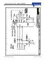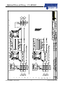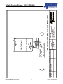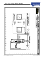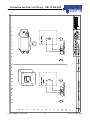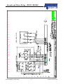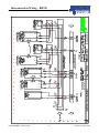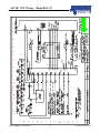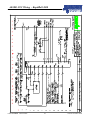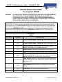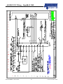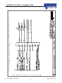
1
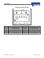
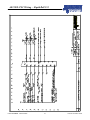
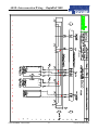
ALLSTAR w/ENCODER CONTROL PANEL
Rapid Roll 355
RapidRoll 3000
975-A OLD NORCROSS ROAD
LAWRENCEVILLE, GA 30045
(770) 338-5000 TEL
(770) 338-5034 FAX
(877) 925-2468 TOLL FREE
Version Nov. 2006
Table of Contents
STATEMENT OF WARRANTY..................................................................................................................2
SAFETY PRACTICES ..................................................................................................................................3
INSTALLATION ...........................................................................................................................................4
Interconnection Wiring ...............................................................................................................................5
ALL-STAR™ DRIVE SYSTEM WITH ENCODER SETUP .....................6
Setting the Door Limits ..................................................................................................................7
Final Checks ...............................................................................................................................................7
Electrical Prints ..............................................................................................................................................8
PANDX3 = Power Wiring..........................................................................................................................8
BPCADS = Reversing Photocell Wiring ....................................................................................................9
BMDADS = Motion Detector Wiring ......................................................................................................10
980086-4023 – Radio Receiver Wiring ....................................................................................................11
BFL-VEK = Floor Loop Wiring ...............................................................................................................12
BPBPS = Pushbutton & Pull Cord Wiring ...............................................................................................13
WAE35BF = Encoder and Motor Wiring.................................................................................................14
WAE35 = Interconnection Wiring – Model 355 ......................................................................................15
AE35B = PLC Wiring – Model 355 .........................................................................................................16
AE35DX = PLC Wiring – Model 355 ......................................................................................................18
WAE3K = Interconnect Wiring – RapidRoll 3000...................................................................................21
AE3KB = PLC Wiring – RapidRoll 3000 ................................................................................................22
AE3KDX – PLC Wiring –RapidRoll 3000 ..............................................................................................24
NOTE
The attached electrical diagrams with these instructions are for reference purposes
only and may show wiring for options not supplied with the door. Please refer to the
actual schematics that are supplied with the control panel.
WARNING
DO NOT INSTALL, OPERATE, OR SERVICE THIS PRODUCT UNLESS YOU
HAVE READAND UNDERSTAND THE SAFETY PRACTICES, WARNINGS,
INSTALLATION, AND MAINTENANCE INSTRUCTIONS CONTAINED IN THIS
MANUAL.
Statement of Warranty
STATEMENT OF WARRANTY
ONE YEAR WARRANTY ON DOOR PANEL, MECHANICAL & ELECTRICAL
COMPONENTS
Albany Door Systems warrants to the original owner of the door that the door panel fabric, mechanical
and electrical components will be free of defects in material and workmanship for a period of twelve
(12) months from the date of shipment.
Only defects brought to the attention of Albany Door Systems during the warranty period will be
covered by his warranty.
Albany Door Systems will replace any component parts, which are found to be defective upon
inspection by an Albany Door Systems representative.
This warranty does not cover damage caused by collision or other abuse of the product. Adjustments
made to the Control Panel or to the mechanical operation of the door without the authorization of
Albany Door Systems will void this warranty.
The replacement provisions shall be the limit of Albany Door Systems responsibility under this
warranty Albany Door Systems shall not be responsible for any other losses or damages due to the
operation of any door or parts covered by this warranty.
No other oral or written representations made by Albany Door Systems or its agents are a part of this
warranty unless specifically set forth in writing by an authorized Albany Door Systems official.
THE ABOVE SET FORTH WARRANTY IS SELLER'S SOLE WARRANTY. SELLER MAKES NO OTHER
WARRANTY OF ANY KIND WHATSOEVER, EXPRESSED OR IMPLIED; AND ALL IMPLIED WARRANTIES
OF MERCHANTABILITY AND FITNESS FOR A PARTICULAR PURPOSE WHICH EXCEED THE
AFORESTATED OBLIGATION ARE HEREBY DISCLAIMED BY SELLER AND EXCLUDED FROM THIS
AGREEMENT.
USW-230.99
PART NUMBER 980076-0004
2
Version November 2006
Safety Practices
SAFETY PRACTICES
WARNING
THOROUGHLY READ THESE SAFETY PRACTICES PRIOR TO
INSTALLING, OPERATING, OR SERVICING A HIGH-SPEED, RAPID
ROLL® DOOR. FAILURE TO FOLLOW THESE SAFETY PRACTICES MAY
RESULT IN PROPERTY DAMAGE, PERSONNEL BODILY INJURY, OR
DEATH.
1. Do not operate a Rapid Roll® Door while you are under the influence of drugs or
alcohol.
2. Do not use the door if any parts appear to be broken or damaged.
3. Stay clear of the door while it is operating.
4. Keep hands and feet clear of the door at all times.
5. Do not drive through the door opening unless door is completely open.
6. Maintain a clear door opening at all times. Keep the door opening free of any
obstructions.
7. Remove power at the fused disconnect during all electrical or mechanical service.
OSHA requires a disconnect to be properly tagged and locked out during all
maintenance or service of equipment.
8. All electrical troubleshooting or service must be performed by a qualified electrician
or service person and must meet all applicable local, state, federal, and other
governing agency codes.
9. USE EXTREME CAUTION when it is necessary to service the control panel while
it is energized.
WARNING
CONTROL PANEL CONTAINS HIGH VOLTAGE. QUALIFIED ELECTRICAL
PERSONNEL SHOULD PERFORM THE FOLLOWING PROCEDURES ONLY.
WIRING MUST MEET ALL LOCAL, STATE, FEDERAL, INTERNATIONAL, OR
OTHER GOVERNMENT AGENCY CODES. FAILURE TO DO COULD RESULT IN
SERIOUS INJURY OR DEATH.
If you have any questions, please contact your local Albany service provider for
assistance. Otherwise contact Albany Door Systems 1-877-925-2468 for information on
your local distributor.
PART NUMBER 980076-0004
3
Version November 2006
Installation
INSTALLATION
The following instructions are guidelines for electrically installing a generic Rapid® Roll Door with and
All-Star Drive System. Actual wiring may be different based on what options; special instructions,
special components, etc. were ordered with the door. Consult the electrical schematics that are supplied
with the door. These should be located inside the door’s control panel.
WARNING
CONTROL PANEL CONTAINS HIGH VOLTAGE. QUALIFIED ELECTRICAL
PERSONNEL SHOULD PERFORM THE FOLLOWING PROCEDURES ONLY.
WHENEVER REMOVING POWER FROM THE CONTROL PANEL, WAIT AT LEAST 1
MINUTE PRIOR TO SERVICING TO ALLOW CAPACITORS INSIDE THE FREQUENCY
INVERTER TO DRAIN. WIRING MUST MEET ALL LOCAL, STATE, FEDERAL,
INTERNATIONAL, OR OTHER GOVERNMENT AGENCY CODES. FAILURE TO DO SO
COULD RESULT IN SERIOUS INJURY OR DEATH.
NOTE
TO AID THE WIRING AND SERVICE OF ALL ELECTRICAL CIRCUITS, TAG OR LABEL ALL
WIRE ENDS DURING THE FOLLOWING ELECTRICAL INSTALLATION. HIGH VOLTAGE
POWER LEADS TO THE DRIVE UNIT MUST BE RUN IN A SEPARATE CONDUIT FROM THE
LOW VOLTAGE CONTROL WIRES.
1. Ensure the mechanical installation of the door is complete.
2. Mount the control panel at a serviceable height on the drive side of the door.
3. Run two electrical conduits from the control panel to the drive unit. Install a suitable
junction box at the drive unit for the motor leads. RUN ENCODER WIRE IN A
SEPARATE CONDUIT! Install a separate suitable junction box for the Encoder
wiring.
4. Run conduits from the control panel to the side frame(s) to accommodate the door
jamb photocell(s) and the contactless safety edge (if supplied).
5. Install the pressure switch onto the bottom beam. Run the retractile cord to the control
panel. Secure the retractile cable (if equipped) to the drive side side frame cover using
supplied cable clamp.
6. Install all the actuators and wire according to the electrical wiring diagrams.
7. Install a non-fused disconnect beside the control panel.
CAUTION
VERIFY ALL FIELD WIRING TO ENSURE TERMINAL CONNECTIONS ARE TIGHT AND
CORRECT. A FUSED DISCONNECT IS REQUIRED FOR EACH ALBANY DOOR AS A MEANS
OF DISCONNECTING INCOMING POWER FROM THE CONTROL PANEL. THIS
DISCONNECT IS NORMALLY SUPPLIED BY OTHERS.
PART NUMBER 980076-0004
4
Version November 2006
Installation
Interconnection Wiring
Label
What
Plug
Location
X31
X33
X35
X36
X37.1
X38.1
THERMAL SWITCH
TOP OPEN PROX.
PHOTOCELL RECEIVER
PHOTOCELL TRANSMITTER
CSE RECIEVER
CSE TRANSMITTER
3 WIRE
3 WIRE
3 WIRE
3 WIRE
4 WIRE
4 WIRE
BLK. WIRE MOTOR
BLK. WIRE SIDE FRAME
LEFT SIDE FRAME
RIGHT SIDE FRAME
RIGHT SIDE FRAME
LEFT SIDE FRAME
PART NUMBER 980076-0004
5
Version November 2006
Installation
ALL-STAR™ DRIVE SYSTEM WITH ENCODER SETUP
1. Located on the side frame, pull
down on the brake
disengagement lever to release
the brake. While the brake is
released, manually move the
door to the halfway point by
pulling the door down. Allow
brake to re-engage.
CAUTION
WHEN MANUALLY MOVING THE DOOR, GRAB HOLD OF THE ALUMINUM
OF THE BOTTOMBEAM. DO NOT PULL ON THE YELLOW, AS IT MAY TEAR.
2. Apply power to the control panel. Check for correct line voltage at FU1, FU2, and FU3 with a
voltmeter. (Using a 460VAC to a 230 VAC inverter will result in damage to the inverter!)
Ensure the POWER LED’s on both the PLC and frequency inverter are lit. Also ensure that the
RUN LED is lit on the PLC.
CAUTION
ALL STEPS ASSOCIATED WITH SETTING THE DOOR LIMITS MUST BE
PERFORMED WITH EMERGENCY STOP BUTTON PULLED OUT.
3. Pull out the emergency stop button and put the system into the setup mode by pressing the SETUP
button (located on the control panel backplate). The RESET button on the face of the panel should
be illuminated. The 11-CR relay should also be energized also at this point. On the PLC the Y0, Y5
lights will be lit.
4. Using the UP/DOWN JOG DOOR switch located on the control panel backplate (small rocker
switch), jog the door in the up direction. If the door opens, then go to the next step. If the door
closes, then the phase rotation on the drive unit is backwards. Swap two of the three motor leads in
the panel to change the motor rotation (Terminals T11, T12, and T13).
IMPORTANT NOTE
FOR THE FOLLOWING STEPS IT IS IMPORTANT TO ENSURE THE DOOR
IS MOVING WHEN THE RESET BUTTON IS PUSHED TO SET THE CLOSE
LIMIT. DO NOT RELEASE THE JOG SWITCH UNTIL DOOR HAS STOPPED
MOVING.
PART NUMBER 980076-0004
6
Version November 2006
Installation
Setting the Door Limits
1. Press the SETUP button putting the door into the setup mode. The RESET should be illuminated
at this point.
2. Using the JOG SWITCH to run the door down. While the door is closing, press the RESET
button when the door reaches the desired bottom limit position. This would be before the door
actually stops on the ground. The PLC will set this as the doors’ bottom limit. The RESET
button will go out also when you set this limit.
3. Put the system in the setup mode again by pressing the SETUP button.
4. Run the door open using the JOG SWITCH. When door reaches the open limit proximity
switch, it will stop automatically and the top limit position will be set. The PLC will
automatically set this as the doors top limit. The RESET light will also go out at this time.
5. Put the system in the setup mode by pressing the SETUP button.
6. Run the door to the halfway point using the JOG SWITCH. This time release the JOG SWITCH
and allow the door to come to a complete stop. Press the RESET button to clear the setup mode.
7. Push the actuator button. As the door cycles, observe the open and close limits. Reset the limits
as necessary to obtain exact desired limits (repeat steps 1-6 as necessary).
8. Check all actuators for proper operation. Check all reversing photocells for proper operation.
9. Verify the automatic operation of the door. The time delay to close is adjustable via an
adjustment screw on the face of the PLC. If non-automatic mode is desired for door operation,
turn the adjustment screw fully counterclockwise. In non-automatic mode, the actuator must be
pulsed to open the door and pulsed again to close the door.
NOTE
NON-AUTOMATIC MODE CANNOT BE USED WITH MOTION
DETECTORS, LOOP DETECTORS, OR PRESENCE SENSORS.
Final Checks
1. Check photocells for proper operation. Breaking the photocell beam should reverse the door
2. Check all actuators for proper operation.
PART NUMBER 980076-0004
7
Version November 2006
PANDX3 = Power Wiring
PART NUMBER 980076-0004
8
A
Electrical Prints
c o m p a n y o f A lb a n y ln t e r n a t io n a l C o r p .
Electrical Power Prints – RR355, RR3000
Version November 2006
A
BPCADS = Reversing Photocell Wiring
c o m p a n y o f A lb a n y ln t e r n a tio n a l C o r p .
Optional Photocell Wiring – 355, RR3000
PART NUMBER 980076-0004
9
Version November 2006
A
c o m
BMDADS = Motion Detector Wiring
p a n y o f A lb a n y ln t e r n a tio n a l C o r p .
Motion Detector Wiring – RR355, RR3000
PART NUMBER 980076-0004
10
Version November 2006
Radio Receiver Wiring – RR355, RR3000
980086-4023 – Radio Receiver Wiring
PART NUMBER 980076-0004
11
Version November 2006
Floor Loop Wiring – RR355, RR3000
BFL-VEK = Floor Loop Wiring
PART NUMBER 980076-0004
12
Version November 2006
Pushbutton and Pull Cord Wiring – RR355, RR3000
BPBPS = Pushbutton & Pull Cord Wiring
PART NUMBER 980076-0004
13
Version November 2006
A
WAE35BF = Encoder and Motor Wiring
c o m p a n y o f A lb a n y ln t e r n a t io n a l C o r p .
Encoder and Motor Wiring – RR355, RR3000
PART NUMBER 980076-0004
14
Version November 2006
A
WAE35 = Interconnection Wiring – Model 355
c o m p a n y o f A lb a n y ln t e r n a t io n a l C o r p .
Interconnection Wiring – RR355
PART NUMBER 980076-0004
15
Version November 2006
A
c o m
AE35B = PLC Wiring – Model 355
p a n y o f A lb a n y ln t e r n a t io n a l C o r p .
AE35B - PLC Wiring – Rapid Roll 355
PART NUMBER 980076-0004
16
Version November 2006
AE35B Troubleshooting Guide – Rapid Roll 355
TROUBLESHOOTING GUIDE
For programs AE35B
WARNING:
ALL ELECTRICAL TROUBLESHOOTING OR SERVICE MUST BE PERFORMED BY
A QUALIFIED ELECTRICIAN OR SERVICE PERSON AND MUST MEET ALL
APPLICABLE LOCAL, STATE, FEDERAL, AND OTHER GOVERNING AGENCY
CODES. EXERCISE EXTREME CAUTION WHEN IT IS NECESSARY TO SERVICE
THE CONTROL PANEL WHILE IT IS ENERGIZED.
The POWER and RUN green LED’s on the PLC must be on. If not, check for 120V power to terminals
AC12 & ACN. If no power is present, de-energize control panel and check main disconnect and all
control panel fuses. Fuses FU1 thru FU3 are the main power supply to the panel. Fuses FU4 & FU5
are for 120 VAC power supply to the PLC. At least one, red input LED’s on the PLC should be on. If
not, ensure the EMERGENCY STOP button is pulled out. If no inputs turn on, check for missing
jumpers and/or switch wiring in series with the EMERGENCY STOP button (i.e. crank/chain hoist
switch, thermal overloads, inertia brake contact, etc.).
PLC INPUTS
(X0-X7)
INPUTS
(“IN” LED’S)
Terminal #
0
XL0
Encoder Position Signal – Channel A. Flickers when doors runs.
1
XL1
Encoder Position Signal – Channel B. Flickers when doors runs.
2
XL2
Shutdown Devices. Should be lit unless a shutdown device
(E-Stop, Crank Switch, ect) or SRD is activated
3
XL3
SRDS Proximity. Should be lit unless bottom beam is hit out.
3-7
DESCRIPTION
Setup. ALL Should be lit unless the setup button has been tripped.
XA1
Actuator Impulse Open. Will come on for as long as the actuator
has been activated. If on continuously, check actuators.
5
XP1, XP2, XP3
Safety Devices. Photocell, CSE and Reversing edge contacts are
wired in series with this input. Should be on unless a safety device
is activated. (N/C)
6
XL4
Open Reference Prox. Should be on unless door is near open
position.
7
XA2
Reset Button. Will Reset the door when activated.
4
PART NUMBER 980076-0004
17
Version November 2006
A
AE35DX = PLC Wiring – Model 355
c o m p a n y o f A lb a n y ln t e r n a t io n a l C o r p .
AE35DX- PLC Wiring – Rapid Roll 355
PART NUMBER 980076-0004
18
Version November 2006
A
c o m
p a n y o f A lb a n y ln te r n a tio n a l C o r p .
AE35DX- PLC Wiring – Rapid Roll 355
PART NUMBER 980076-0004
19
Version November 2006
AE35DX- Troubleshooting Guide – Rapid Roll 355
TROUBLESHOOTING GUIDE For program AE35DX
WARNING:ALL ELECTRICAL TROUBLESHOOTING OR SERVICE MUST BE PERFORMED BY A QUALIFIED
ELECTRICIAN OR SERVICE PERSON AND MUST MEET ALL APPLICABLE LOCAL, STATE,
FEDERAL, AND OTHER GOVERNING AGENCY CODES. EXERCISE EXTREME CAUTION
WHEN IT IS NECESSARY TO SERVICE THE CONTROL PANEL WHILE IT IS ENERGIZED.
The POWER and RUN green LED’s on the PLC must be on. If not, check for 120V power to terminals
AC12 &ACN. If no power is present, de-energize control panel and check main disconnect and all
control panel fuses. Fuses FU1 thru FU3 are the main power supply to the panel. Fuses FU4 & FU5
are for 120 VAC power supply to the PLC. At least one, red input LED’s on the PLC should be on. If
not, ensure the EMERGENCY STOP button is pulled out. If no inputs turn on, check for missing
jumpers and/or switch wiring in series with the EMERGENCY STOP button (i.e. crank/chain hoist
switch, thermal overloads, inertia brake contact, etc.).
PLC INPUTS (X0-X17)
INPUTS
(“IN” LED’S)
Terminal
#
0
XL0
Encoder Position Signal – Channel A. Flickers when doors runs.
1
XL1
Encoder Position Signal – Channel B. Flickers when doors runs.
2
XL2
Shutdown Devices. Should be lit unless a shutdown device (E-Stop, Crank
Switch, ect.) or SRD is activated
3
XL3
SRDS Proximity. Should be lit unless bottom beam is hit out.
3 THRU
17
DESCRIPTION
Setup. Should be lit unless the setup button has been tripped.
4
XA1
Impulse Open. Will come lit for as long as the actuator has been activated.
If on continuously, check actuators.
5
XP1, XP2,
XP3
Safety Devices. Photocell, CSE and Reversing edge contacts are wired in
series with this input. Should be lit unless a safety device is activated. (N/C)
6
XQ1, XQ2
Interlock. Needs be lit to enable door operation, or jumped out if no interlock
is being using.
7
XA2
Reset Button. Will Reset the door when activated.
10
XL4
Open Reference Proximity. Should be on unless door is near open position.
11
XA3
Actuator Full Height Open. Will come lit for as long as the actuator has
been activated. If on continuously, check actuators.
12
XA4
Actuator Close. Will come on for as long as the actuator has been
activated. If on continuously, check actuators.
13
XA5
Auto/Manual. Jump for non-auto. (Will be lit when in Manual mode)
14
XA6
17
XP4, XP5
Actuator Mid Height Open. Will become lit for as long as the actuator has
been activated. If on continuously, check actuators.
Extra Reversing Photocells. Will be lit (N/C). If no photocells are being
used, should be jumped out for normal door operation.
PART NUMBER 980076-0004
20
Version November 2006
A
WAE3K = Interconnect Wiring – RapidRoll 3000
c o m p a n y o f A lb a n y ln te r n a tio n a l C o r p .
AE3K- Interconnection Wiring – RapidRoll 3000
PART NUMBER 980076-0004
21
Version November 2006
A
AE3KB = PLC Wiring – RapidRoll 3000
c o m p a n y o f A lb a n y ln t e r n a t io n a l C o r p .
AE3KB- PLC Wiring – RapidRoll 3000
PART NUMBER 980076-0004
22
Version November 2006
AE3KB Troubleshooting Guide – RapidRoll 3000
TROUBLESHOOTING GUIDE
For programs AE3KB
WARNING:
ALL ELECTRICAL TROUBLESHOOTING OR SERVICE MUST BE PERFORMED BY
A QUALIFIED ELECTRICIAN OR SERVICE PERSON AND MUST MEET ALL
APPLICABLE LOCAL, STATE, FEDERAL, AND OTHER GOVERNING AGENCY
CODES. EXERCISE EXTREME CAUTION WHEN IT IS NECESSARY TO SERVICE
THE CONTROL PANEL WHILE IT IS ENERGIZED.
The POWER and RUN green LED’s on the PLC must be on. If not, check for 120V power to terminals
AC12 & ACN. If no power is present, de-energize control panel and check main disconnect and all
control panel fuses. Fuses FU1 thru FU3 are the main power supply to the panel. Fuses FU4 & FU5
are for 120 VAC power supply to the PLC. At least one, red input LED’s on the PLC should be on. If
not, ensure the EMERGENCY STOP button is pulled out. If no inputs turn on, check for missing
jumpers and/or switch wiring in series with the EMERGENCY STOP button (i.e. crank/chain hoist
switch, thermal overloads, inertia brake contact, etc.).
PLC INPUTS
(X0-X7)
INPUTS
(“IN” LED’S)
Terminal #
0
XL0
Encoder Position Signal – Channel A. Flickers when doors runs.
1
XL1
Encoder Position Signal – Channel B. Flickers when doors runs.
2
XL2
Shutdown Devices. Should be lit unless a shutdown device
(E-Stop, Crank Switch, ect) or SRD is activated
3
XL3
SRDS Proximity. Should be lit unless bottom beam is hit out.
3-7
DESCRIPTION
Setup. ALL Should be lit unless the setup button has been tripped.
4
XA1
Actuator Impulse Open. Will come on for as long as the actuator
has been activated. If on continuously, check actuators.
5
XP1, XP2, XP3
Safety Devices. Photocell, CSE and Reversing edge contacts are
wired in series with this input. Should be on unless a safety device
is activated. (N/C)
6
XL4
Open Reference Prox. Should be on unless door is near open
position.
7
XA2
Reset Button. Will Reset the door when activated.
PART NUMBER 980076-0004
23
Version November 2006
A
AE3KDX – PLC Wiring –RapidRoll 3000
c o m p a n y o f A lb a n y ln t e r n a t io n a l C o r p .
AE3KDX PLC Wiring – RapidRoll 3000
PART NUMBER 980076-0004
24
Version November 2006
A
c o m p a n y o f A lb a n y ln t e r n a tio n a l C o r p .
AE3KDX PLC Wiring – RapidRoll 3000
PART NUMBER 980076-0004
25
Version November 2006
AE3KDX Troubleshooting Guide – RapidRoll 3000
TROUBLESHOOTING GUIDE For program AE35DX
WARNING:ALL ELECTRICAL TROUBLESHOOTING OR SERVICE MUST BE PERFORMED BY A QUALIFIED
ELECTRICIAN OR SERVICE PERSON AND MUST MEET ALL APPLICABLE LOCAL, STATE,
FEDERAL, AND OTHER GOVERNING AGENCY CODES. EXERCISE EXTREME CAUTION
WHEN IT IS NECESSARY TO SERVICE THE CONTROL PANEL WHILE IT IS ENERGIZED.
The POWER and RUN green LED’s on the PLC must be on. If not, check for 120V power to terminals
AC12 &ACN. If no power is present, de-energize control panel and check main disconnect and all
control panel fuses. Fuses FU1 thru FU3 are the main power supply to the panel. Fuses FU4 & FU5
are for 120 VAC power supply to the PLC. At least one, red input LED’s on the PLC should be on. If
not, ensure the EMERGENCY STOP button is pulled out. If no inputs turn on, check for missing
jumpers and/or switch wiring in series with the EMERGENCY STOP button (i.e. crank/chain hoist
switch, thermal overloads, inertia brake contact, etc.).
PLC INPUTS (X0-X17)
INPUTS
(“IN” LED’S)
Terminal
#
0
XL0
Encoder Position Signal – Channel A. Flickers when doors runs.
1
XL1
Encoder Position Signal – Channel B. Flickers when doors runs.
2
XL2
Shutdown Devices. Should be lit unless a shutdown device (E-Stop, Crank
Switch, ect.) or SRD is activated
3
XL3
SRDS Proximity. Should be lit unless bottom beam is hit out.
3 THRU
17
DESCRIPTION
Setup. Should be lit unless the setup button has been tripped.
4
XA1
Impulse Open. Will come lit for as long as the actuator has been activated.
If on continuously, check actuators.
5
XP1, XP2,
XP3
Safety Devices. Photocell, CSE and Reversing edge contacts are wired in
series with this input. Should be lit unless a safety device is activated. (N/C)
6
XQ1, XQ2
Interlock. Needs be lit to enable door operation, or jumped out if no interlock
is being using.
7
XA2
Reset Button. Will Reset the door when activated.
10
XL4
Open Reference Proximity. Should be on unless door is near open position.
11
XA3
Actuator Full Height Open. Will come lit for as long as the actuator has
been activated. If on continuously, check actuators.
12
XA4
Actuator Close. Will come on for as long as the actuator has been
activated. If on continuously, check actuators.
13
XA5
Auto/Manual. Jump for non-auto. (Will be lit when in Manual mode)
14
XA6
17
XP4, XP5
Actuator Mid Height Open. Will become lit for as long as the actuator has
been activated. If on continuously, check actuators.
Extra Reversing Photocells. Will be lit (N/C). If no photocells are being
used, should be jumped out for normal door operation.
PART NUMBER 980076-0004
26
Version November 2006
Notes
Allstar with Encoder Control Panel Manual
DOCUMENT TITLE
980076-0001
DOCUMENT NUMBER
DOOR MODEL(S)
ISSUE DATE
2002-08-01
Revised November 2006
ELECTRONIC FILE
Allstar with Encoder.DOC
ASSEMBLY
CONTROLS
REPLACES
ORIGINATOR
Rick Walton / Robert Rundle
Revision by Davey Riley
MANAGER
APPROVAL/DATE
PART NUMBER 980076-0004
27
Allstar Electrical Manual Encoder V2
Version November 2006