1
Tachometer Installation and Operation Instructions
Addendum for Comp Eliminator II Tachometer
Siemens VDO
®
Allentown, Pennsylvania USA
THE INSTRUCTIONS FOR OPERATION AND ELECTRICAL WIRING FOR THIS TACHOMETER FOLLOWS. USE IS RESTRICTED TO 12 VOLT NEGATIVE GROUND ELECTRICAL SYSTEMS.
IMPORTANT: The installation and general
wiring for this tachometer is essentially the
same as for those mentioned elsewhere in
these instructions. There are minor
differences, however, which are described here.
Please read and understand them before
proceeding.
I. Comp Eliminator II Switch Settings and Wiring
Wiring for the Comp Eliminator II is the same as for the other
tachometers. Please refer to the proper sections of the main
Eliminator Tachometer Installation and Operation Instructions to
determine the proper switch settings and wiring for the vehicle and tachometer you are using. Also, refer to the diagrams
contained in this addendum and note the subtle changes between the Comp Eliminator II and the other Eliminator Tachometers.
II. Comp Eliminator II Operation
The unique feature of this tachometer is a high/low RPM
tell-tale memory. Take advantage of this feature by performing the following steps:
START:
1. Be sure to bring the car to speed before pressing the
START/STOP button on the keypad. NOTE: This is criti-
cal! If the START/STOP button is pressed before the car has
reached running speed, or if the process is not stopped (by pushing STOP) before slowing the
car, an incorrect low RPM
value will be stored in the
tach! Pressing the
START/STOP button
will cause the tach to begin storing high and low
RPM values. This is indicated by a one-second blink
of the shift light LED, followed
by a flicker every second to show that the tach is still searching for high and low levels.
STOP:
2. The tachometer is programmed to search for high and low
RPM levels. To stop this function at any time simply press
ANY button on the keypad. Function stop is indicated by
two blinks of the shift light LED.
RECALL:
3. To recall high and low RPM values, press the
HI/LOW button on the keypad. The tach pointer
will move to the high RPM reading. A second
press of the HI/LOW button will move the pointer
to the low RPM value. Pressing the HI/LOW button again will repeat the process.
HI
LOW
TACH
SET
START
STOP
*5((1
,JQLWLRQ 7DFKRPHWHU VLJQDO FRQQHFWLRQ
:+,7(
2SWLRQDO H[WHULRU VKLIW OLJKW
%/$&.
7DFK JURXQG FRQQHFW WR FRPPRQ FKDVVLV JURXQG
5('
YROW SRZHU FRQQHFW WR IXVH SDQHO
6+,(/'
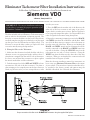
Diagram A
Comp Eliminator II Wire Color Code and Hookup Description
Part # 0 511 012 411 Rev. 07/03