1
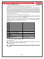
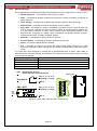
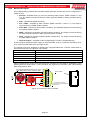
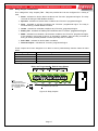
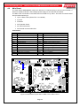
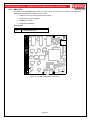
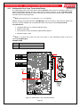
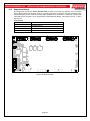
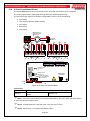
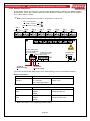
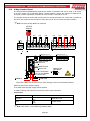
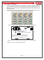
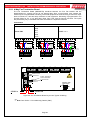
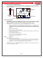
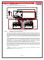
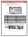
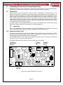
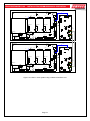
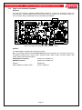
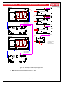
EN54 FIREFINDER PLUS INSTALLATION,COMMISSIONING & OPERATION 12.8.2 Remote Relay Board In the remote version the Comms In and Out Terminal Block TB9 is cabled to the RS485 Comms terminal block TB1on the Communications Extender Board (see section 5.12) and can be installed up to 1.2kms from the FACP. Note: Can be powered from the panel or an external 27 volt source. N/0 = Normally Open COM = Common N/C = Normally Closed O/P 1 COM N/0 N/C TB1 O/P 2 N/0 COM N/C TB2 N/0 O/P 3 COM N/C TB3 N/0 COM N/C N/0 TB4 O/P 1 COM O/P 4 N/0 N/C TB1 N/0 O/P 2 COM N/C TB2 N/0 O/P 5 COM N/C TB5 O/P 3 COM N/C N/0 TB3 N/C COM N/C TB4 O/P 5 N/0 COM N/C TB5 N/0 O/P 7 N/0 N/C COM O/P 6 COM N/C TB6 N/0 O/P 7 COM N/C TB7 Fit EOL Termination Link 1 if Last Module To TB3 on the Main on Comms Bus and/or Zone TB10 Card Mimic Card + - + - O/P 8 N/0 TB7 TB6 O/P 4 COM O/P 6 N/0 COM N/C TB8 N/0 O/P 8 COM N/C TB8 Address SW (See Note) O N ON TB9 1 2 3 4 SW1 RS485+ SHD RS485+ SHD RS485RS485- RS485 COMMS IN / OUT 27 Volts In (External Supply) 27 Volts Out (External Supply) Figure 84: Remote 8 Way Relay Board Front View showing connectors and Address Switch Relay Connections Terminal/s TB1 to 8 Function N/O = Normally Open, C = Common N/C = Normally Closed Relay 1 to 8 Communications Connections Terminal TB9 TB9 Function RS485+ RS485Shield RS485+ RS485Shield Communications In Communications Out Note: See Section 17 for Addressing Details (SW1) Page 59