1
Chapter 5: Communication
7193 Owner’s Guide
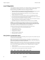
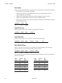
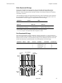
RS-232C Technical Specifications
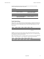
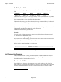
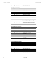
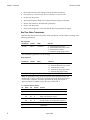
This section describes the pin settings for the connectors and the RS-232C interface
parameters. The RS-232C parameters are selected by setting the DIP switches on the
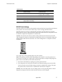
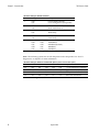
printed circuit board. See “RS-232C Switch Settings” on the next page for the position of
the DIP switches. The RS-232C parameters must match those of the host computer.
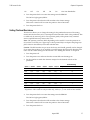
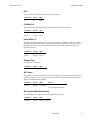
Connectors
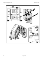
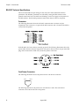
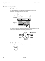
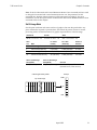
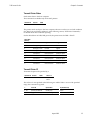
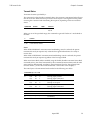
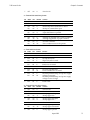
The following illustration shows the RS-232C communication connector and pin
assignments. The connector is a 9-pin male D-shell connector and is located in the hollow
cavity under the printer.
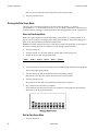
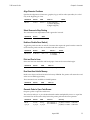
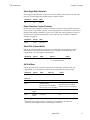
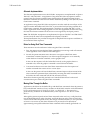
With RS-232C, the 7193 is always remotely powered. The following illustration shows the
power cable connector and pin assignments. The power cable connector is 6-pin mini DIN
plug and is located in the small cavity under the printer at the front.
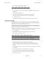
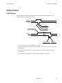
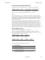
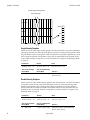
Cash Drawer Connectors
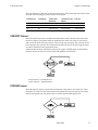
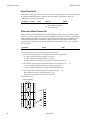
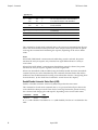
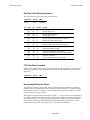
The following illustration shows the pinouts for the cash drawer connector.
Pin 1
Pin 6
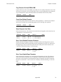
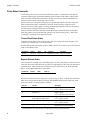
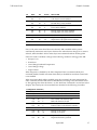
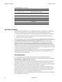
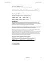
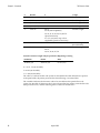
The following table shows the pinouts for cash drawers 1 and 2. The cash drawer
connectors are located at the rear of the printer.
36
August 1998