1
Si38-304
Malfunction of Discharge Pipe Thermistor
(R31~33T)......................................................207
Malfunction of Drain Level Control System
(33H) ..............................................................180
Malfunction of High Pressure Sensor....................211
Malfunction of Inverter Radiating Fin
Temperature Rise ..........................................213
Malfunction of Inverter Radiating Fin Temperature
Rise Sensor ...................................................220
Malfunction of Low Pressure Sensor ....................212
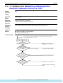
Malfunction of Moving Part of Electronic Expansion
Valve (20E) ....................................................185
Malfunction of Moving Part of Electronic Expansion
Valve (Y1E, Y2E) ...........................................200
Malfunction of Outdoor Unit Fan Motor .................198
Malfunction of Receiver Gas Pipe Thermistor
(R5T)..............................................................210
Malfunction of Swing Flap Motor (MA) ..................183
Malfunction of System, Refrigerant System Address
Undefined.......................................................239
Malfunction of Thermistor (R1T) for Suction Air....191
Malfunction of Thermistor (R2T)
for Heat Exchanger ........................................189
Malfunction of Thermistor (R2T)
for Suction Pipe..............................................208
Malfunction of Thermistor (R3T) for Gas Pipes.....190
Malfunction of Thermistor (R4T) for
Outdoor Unit Heat Exchanger ........................209
Malfunction of Thermistor for Outdoor Air (R1T)...205
Malfunction of Thermostat Sensor in Remote
Controller .......................................................192
Malfunction of Transmission Between Central
Remote Controller and
Indoor Unit .................................... 236, 240, 246
Malfunction of Transmission Between Indoor and
Outdoor Units in the Same System................232
Malfunction of Transmission Between
Indoor Units....................................................226
Malfunction of Transmission Between Inverter and
Control PC Board...........................................217
Malfunction of Transmission Between Master and
Slave Remote Controllers ..............................231
Malfunction of Transmission Between Optional
Controllers for Centralized Control........ 242, 249
Malfunction of Transmission Between
Outdoor Units.................................................229
Malfunction of Transmission Between Remote
Controller and Indoor Unit..............................228
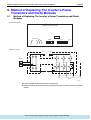
Method of Replacing The Inverter’s
Power Transistors and Diode Modules ..........324
Diode Module .................................................325
Power Transistor IGBT
(On Inverter PC Board)......................325
O
Operation Lamp Blinks..........................................253
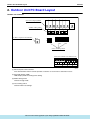
Outdoor Unit PC Board Layout .............................126
P
PC Board Defect .......................... 179, 193, 241, 248
vi
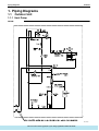
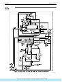
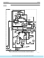
Piping Diagrams
FXC, FXF, FXK, FXYD, FXS, FXYB, FXM, FXH,
FXA, FXL, FXN ................................. 270
RX14M RX16M.............................................. 269
RX5M............................................................. 267
RX8M RX10M RX12M................................... 268
RXY14M RXY16M ......................................... 266
RXY5M .......................................................... 264
RXY8M RXY10M RXY12M............................ 265
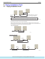
Piping Installation Point ........................................ 314
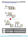
The Example of A Wrong Pattern .................. 315
Power Supply Insufficient or Instantaneous
Failure ........................................................... 223
Pressure Sensor .................................................. 323
R
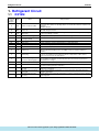
Refrigerant Circuit
RXY14, 16M .................................................... 68
RXY5M ............................................................ 64
RXY8, 10, 12M ................................................ 66
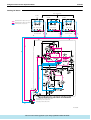
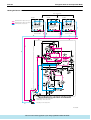
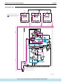
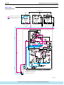
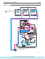
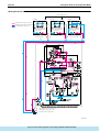
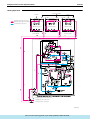
Refrigerant Flow for Each Operation Mode............ 73
RXY14, 16M .................................................... 81
RXY5M ............................................................ 73
RXY8, 10, 12M ................................................ 77
Refrigerant Overcharged...................................... 203
Refrigerant System not Set, Incompatible Wiring/
Piping ............................................................ 238
Remote Controller Self-Diagnosis Function ......... 173
Replacement procedure for INV compressor,
VRV II RX(Y)5M-48M.................................... 262
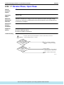
Reverse Phase, Open Phase............................... 222
S
Self-diagnosis by Wired Remote Controller ......... 166
Setting of Air Flow Direction
Adjustment Range......................................... 134
Setting of Demand Operation
Image of operation in the case of A ............... 156
Image of operation in the case of A and B..... 156
Image of operation in the case of B ............... 156
Setting of Low Noise Operation
Image of operation in the case of A ............... 154
Image of operation in the case of A, B........... 154
Image of operation in the case of B ............... 154
Simplified Remote Controller................................ 129
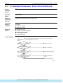
Standard Compressor Motor Overcurrent/Lock ... 197
T
Thermostat Sensor in Remote Controller
Cooling........................................................... 117
Heating .......................................................... 118
Turn power on ...................................................... 122
U
Unit No. transfer ................................................... 172
W
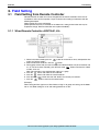
Wired Remote Controller...................................... 127
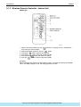
Wireless Remote Controller - Indoor Unit............. 128
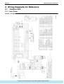
Wiring Diagrams for Reference
RX14MY1 RX16MY1 ..................................... 279
: http://splitoff.ru/tehn-doc.html
Drawings & Flow Charts