1
EP6000
GENERAL,
MECHANICAL/
ELECTRICAL
CONTENTS
GENERAL
1. SAFETY INFORMATION . . . . . . . . . . . . . . . . . . . . . . . . . . . . . . . .G-1
2. TECHNICAL HIGHLIGHTS . . . . . . . . . . . . . . . . . . . . . . . . . . . . . . .G-2
3. SPECIFICATIONS . . . . . . . . . . . . . . . . . . . . . . . . . . . . . . . . . . . . . .G-3
4. SPACE REQUIREMENTS . . . . . . . . . . . . . . . . . . . . . . . . . . . . . . .G-7
5. PRECAUTIONS FOR INSTALLATION . . . . . . . . . . . . . . . . . . . . . G-8
6. PRECAUTIONS FOR USE . . . . . . . . . . . . . . . . . . . . . . . . . . . . . . .G-9
7. HANDLING OF THE CONSUMABLES . . . . . . . . . . . . . . . . . . . . . G-10
8. SYSTEM OPTIONS . . . . . . . . . . . . . . . . . . . . . . . . . . . . . . . . . . . . .G-11
9. PARTS IDENTIFICATION . . . . . . . . . . . . . . . . . . . . . . . . . . . . . . . .G-12
MECHANICAL/ELECTRICAL
1. CROSS-SECTIONAL VIEW . . . . . . . . . . . . . . . . . . . . . . . . . . . . . .M-1
2. COPY PROCESS . . . . . . . . . . . . . . . . . . . . . . . . . . . . . . . . . . . . . .M-3
3. DRIVE SYSTEM . . . . . . . . . . . . . . . . . . . . . . . . . . . . . . . . . . . . . . .M-5
4. SEQUENTIAL EXPLANATION . . . . . . . . . . . . . . . . . . . . . . . . . . . . M-7
5. WATCHDOG (CPU OVERRUN MONITOR) FUNCTION . . . . . . . M-11
6. MALFUNCTION BYPASS FUNCTION. . . . . . . . . . . . . . . . . . . . . . M-14
7. IMAGE STABILIZATION SYSTEM. . . . . . . . . . . . . . . . . . . . . . . . . M-16
8. PC DRUM. . . . . . . . . . . . . . . . . . . . . . . . . . . . . . . . . . . . . . . . . . . . .M-25
8-1. PC Drum . . . . . . . . . . . . . . . . . . . . . . . . . . . . . . . . . . . . . . . . . .M-25
8-2. PC Drum Drive Mechanism/Control . . . . . . . . . . . . . . . . . . . . M-25
8-3. Grounding of the PC Drum . . . . . . . . . . . . . . . . . . . . . . . . . . . M-27
8-4. Drum Dry Heater . . . . . . . . . . . . . . . . . . . . . . . . . . . . . . . . . . .M-27
9. DRUM CHARGING . . . . . . . . . . . . . . . . . . . . . . . . . . . . . . . . . . . . .M-28
9-1. PC Drum Charge Corona . . . . . . . . . . . . . . . . . . . . . . . . . . . . M-28
9-2. Control of the PC Drum Charge Corona . . . . . . . . . . . . . . . . M-30
9-3. PC Drum Charge Corona Wires Cleaning
Mechanism/Control . . . . . . . . . . . . . . . . . . . . . . . . . . . . . . . . .M-31
9-4. Ozone Filter . . . . . . . . . . . . . . . . . . . . . . . . . . . . . . . . . . . . . . .M-33
i
CONTENTS
10. OPTICAL SECTION. . . . . . . . . . . . . . . . . . . . . . . . . . . . . . . . . . . . .M-34
10-1. Construction . . . . . . . . . . . . . . . . . . . . . . . . . . . . . . . . . . . . . .M-34
10-2. Function of Exposure Components . . . . . . . . . . . . . . . . . . . M-36
10-3. Exposure Lamp LA1 Control . . . . . . . . . . . . . . . . . . . . . . . . . M-37
10-4. Intensity Correction . . . . . . . . . . . . . . . . . . . . . . . . . . . . . . . .M-42
10-5. Scanner and Mirrors Carriage Moving Mechanism . . . . . . . M-43
10-6. Scanner Motor M11 Control . . . . . . . . . . . . . . . . . . . . . . . . . M-45
10-7. Lens Drive Mechanism/Control . . . . . . . . . . . . . . . . . . . . . . . M-47
10-8. Optical Section Cooling Fan Motor . . . . . . . . . . . . . . . . . . . . M-53
11. ORIGINAL SIZE DETECTING SYSTEM. . . . . . . . . . . . . . . . . . . . M-54
11-1. Construction . . . . . . . . . . . . . . . . . . . . . . . . . . . . . . . . . . . . . .M-54
11-2. Construction of the Original Size Detecting Sensor . . . . . . M-55
11-3. Original Detection Method. . . . . . . . . . . . . . . . . . . . . . . . . . . M-56
11-4. Sensor Locations . . . . . . . . . . . . . . . . . . . . . . . . . . . . . . . . . .M-58
11-5. Original Size Detection . . . . . . . . . . . . . . . . . . . . . . . . . . . . .M-59
11-6. Original Size Detection Processing . . . . . . . . . . . . . . . . . . . M-60
12. IMAGE ERASE LAMP . . . . . . . . . . . . . . . . . . . . . . . . . . . . . . . . . . .M-62
12-1. Image Erase Lamp LA3 . . . . . . . . . . . . . . . . . . . . . . . . . . . . .M-62
12-2. Image Erase Lamp LA3 ON/OFF Control . . . . . . . . . . . . . . M-63
12-3. Control for Each Erase Function. . . . . . . . . . . . . . . . . . . . . . M-64
13. DEVELOPING UNIT . . . . . . . . . . . . . . . . . . . . . . . . . . . . . . . . . . . .M-69
13-1. Construction . . . . . . . . . . . . . . . . . . . . . . . . . . . . . . . . . . . . . .M-69
13-2. Developing Unit Drive Mechanism . . . . . . . . . . . . . . . . . . . . M-70
13-3. Developer Flow . . . . . . . . . . . . . . . . . . . . . . . . . . . . . . . . . . .M-71
13-4. Magnetic Pole Positioning . . . . . . . . . . . . . . . . . . . . . . . . . . . M-73
13-5. ATDC Sensor . . . . . . . . . . . . . . . . . . . . . . . . . . . . . . . . . . . . .M-75
13-6. Control for Abnormally Low T/C . . . . . . . . . . . . . . . . . . . . . . M-78
13-7. Sub Hopper Toner Replenishing Mechanism/Control . . . . . M-80
13-8. Sub Hopper Toner Empty Detecting Mechanism/Control . . M-82
13-9. Main Hopper Toner Replenishing Mechanism/Control . . . . M-85
13-10. Auxiliary Toner Replenishing . . . . . . . . . . . . . . . . . . . . . . . M-88
13-11. Developing Bias . . . . . . . . . . . . . . . . . . . . . . . . . . . . . . . . . .M-90
13-12. Developing Unit Dehumidifying Heater . . . . . . . . . . . . . . . M-91
13-13. Toner Suction Fan Motor. . . . . . . . . . . . . . . . . . . . . . . . . . . M-92
14. PRE-IMAGE TRANSFER ERASE LAMP . . . . . . . . . . . . . . . . . . . . M-93
14-1. Pre-Image Transfer Erase Lamp . . . . . . . . . . . . . . . . . . . . . M-93
14-2. Pre-Image Transfer Erase Lamp LA4 ON/OFF Control . . . M-93
ii
CONTENTS
15. PAPER TAKE-UP/FEED SECTION . . . . . . . . . . . . . . . . . . . . . . . . M-95
15-1. Construction . . . . . . . . . . . . . . . . . . . . . . . . . . . . . . . . . . . . . .M-95
15-2. Drawer-in-Position Detection . . . . . . . . . . . . . . . . . . . . . . . . M-96
15-3. Paper Empty Detection . . . . . . . . . . . . . . . . . . . . . . . . . . . . .M-97
15-4. Paper Lifting/Lowering Mechanism/Control . . . . . . . . . . . . . M-99
15-5. Paper Stack Lowering/Drawer Locking Mechanism/
Control (Inch Areas). . . . . . . . . . . . . . . . . . . . . . . . . . . . . . . .M-103
15-6. Paper Level Detection . . . . . . . . . . . . . . . . . . . . . . . . . . . . . .M-105
15-7. 3rd-Drawer-in-Position Detection . . . . . . . . . . . . . . . . . . . . . M-107
15-8. 3rd Drawer Paper Empty Detection . . . . . . . . . . . . . . . . . . . M-108
15-9. Main Tray Paper Stack Lifting/Lowering Mechanism/
Control . . . . . . . . . . . . . . . . . . . . . . . . . . . . . . . . . . . . . . . . . .M-110
15-10. 3rd Drawer Paper Level Detecting Mechanism . . . . . . . . . M-114
15-11. Shifter Drive Mechanism/Control . . . . . . . . . . . . . . . . . . . . M-115
15-12. 3rd Drawer Lock/Release . . . . . . . . . . . . . . . . . . . . . . . . . . M-118
15-13. Paper Dehumidifying Heaters . . . . . . . . . . . . . . . . . . . . . . . M-119
15-14. Drawer Paper Take-Up Mechanism/Control . . . . . . . . . . . M-120
15-15. Vertical Transport Drive Mechanism . . . . . . . . . . . . . . . . . M-126
15-16. Multi Bypass Table. . . . . . . . . . . . . . . . . . . . . . . . . . . . . . . .M-128
16. TRANSPORT/SYNCHRONIZING ROLLERS UNIT . . . . . . . . . . . M-136
16-1. Construction . . . . . . . . . . . . . . . . . . . . . . . . . . . . . . . . . . . . . .M-136
16-2. Paper Dust Remover . . . . . . . . . . . . . . . . . . . . . . . . . . . . . . .M-137
16-3. Transport Roller Drive Mechanism . . . . . . . . . . . . . . . . . . . . M-137
16-4. Transport Roller Drive Control . . . . . . . . . . . . . . . . . . . . . . . M-138
16-5. Synchronizing Roller Drive Mechanism . . . . . . . . . . . . . . . . M-139
16-6. Synchronizing Roller Drive Control. . . . . . . . . . . . . . . . . . . . M-140
16-7. Prevention of Low Image Density on Copy . . . . . . . . . . . . . M-142
17. IMAGE TRANSFER/PAPER SEPARATOR CORONAS . . . . . . . . M-143
17-1. Image Transfer/Paper Separator Coronas. . . . . . . . . . . . . . M-143
17-2. Image Transfer/Paper Separator Coronas Control . . . . . . . M-144
17-3. Image Transfer/Paper Separator Corona Wires Cleaning
Mechanism/Control . . . . . . . . . . . . . . . . . . . . . . . . . . . . . . . .M-145
17-4. Image Transfer/Paper Separator Coronas Assy Retracting
Mechanism . . . . . . . . . . . . . . . . . . . . . . . . . . . . . . . . . . . . . . .M-148
17-5. Ozone Filter . . . . . . . . . . . . . . . . . . . . . . . . . . . . . . . . . . . . . .M-149
18. CLEANING UNIT . . . . . . . . . . . . . . . . . . . . . . . . . . . . . . . . . . . . . . .M-150
18-1. Construction of the Cleaning Unit . . . . . . . . . . . . . . . . . . . . . M-150
18-2. Cleaning Blade Moving Mechanism . . . . . . . . . . . . . . . . . . . M-151
iii
CONTENTS
18-3. Toner Conveying/Collecting Mechanism . . . . . . . . . . . . . . . M-152
18-4. Pre-Cleaning Erase Lamp LA5 ON/OFF Control. . . . . . . . . M-154
18-5. PC Drum Paper Separator Fingers Moving Mechanism/
Control . . . . . . . . . . . . . . . . . . . . . . . . . . . . . . . . . . . . . . . . . .M-155
18-6. Cleaning Bias (Option) . . . . . . . . . . . . . . . . . . . . . . . . . . . . .M-159
19. MAIN ERASE LAMP . . . . . . . . . . . . . . . . . . . . . . . . . . . . . . . . . . . .M-160
19-1. Main Erase Lamp . . . . . . . . . . . . . . . . . . . . . . . . . . . . . . . . . .M-160
19-2. Main Erase Lamp LA2 ON/OFF Control. . . . . . . . . . . . . . . . M-160
20. TRANSPORT SECTION . . . . . . . . . . . . . . . . . . . . . . . . . . . . . . . . .M-162
20-1. Transport Section. . . . . . . . . . . . . . . . . . . . . . . . . . . . . . . . . .M-162
20-2. Suction Fan Motor M18 Control . . . . . . . . . . . . . . . . . . . . . . M-163
21. FUSING UNIT . . . . . . . . . . . . . . . . . . . . . . . . . . . . . . . . . . . . . . . . .M-164
21-1. Construction . . . . . . . . . . . . . . . . . . . . . . . . . . . . . . . . . . . . . .M-164
21-2. Fusing Rollers and Web Roller . . . . . . . . . . . . . . . . . . . . . . . M-166
21-3. Drive for the Fusing Unit . . . . . . . . . . . . . . . . . . . . . . . . . . . . M-167
21-4. Fusing Rollers Pressure Mechanism . . . . . . . . . . . . . . . . . . M-169
21-5. Oil Application Mechanism . . . . . . . . . . . . . . . . . . . . . . . . . . M-169
21-6. Cleaning Web Take-Up Mechanism/Control . . . . . . . . . . . . M-170
21-7. Fusing Temperature Control . . . . . . . . . . . . . . . . . . . . . . . . . M-172
21-8. CPM Control . . . . . . . . . . . . . . . . . . . . . . . . . . . . . . . . . . . . .M-176
22. EXIT/DUPLEX SWITCHING UNIT . . . . . . . . . . . . . . . . . . . . . . . . . M-178
22-1. Construction . . . . . . . . . . . . . . . . . . . . . . . . . . . . . . . . . . . . . .M-178
22-2. Exit/Duplex Switching Mechanism/Control . . . . . . . . . . . . . M-179
23. DUPLEX UNIT TURNOVER MECHANISM . . . . . . . . . . . . . . . . . . M-181
23-1. Construction . . . . . . . . . . . . . . . . . . . . . . . . . . . . . . . . . . . . . .M-181
23-2. Drive Mechanism . . . . . . . . . . . . . . . . . . . . . . . . . . . . . . . . . .M-182
23-3. Duplex Unit Turnover Mechanism . . . . . . . . . . . . . . . . . . . . M-183
24. DUPLEX UNIT . . . . . . . . . . . . . . . . . . . . . . . . . . . . . . . . . . . . . . . . .M-186
24-1. Construction . . . . . . . . . . . . . . . . . . . . . . . . . . . . . . . . . . . . . .M-186
24-2. Trailing Gate Unit Moving Mechanism/Control . . . . . . . . . . M-188
24-3. Gate Switching Mechanism/Control . . . . . . . . . . . . . . . . . . . M-189
24-4. Trailing Gate Unit Moving and Gate Switching
Operations . . . . . . . . . . . . . . . . . . . . . . . . . . . . . . . . . . . . . . .M-190
24-5. Front/Rear Edge Guide Plate Drive Mechanism/
Control . . . . . . . . . . . . . . . . . . . . . . . . . . . . . . . . . . . . . . . . . .M-191
24-6. Storing of Copies in Duplex Unit . . . . . . . . . . . . . . . . . . . . . . M-193
iv
CONTENTS
24-7. Leading Edge Guide Plate and Duplex Paper Take-Up
Drive Mechanism/Control . . . . . . . . . . . . . . . . . . . . . . . . . . . M-195
24-8. Duplex Paper Take-Up Operation . . . . . . . . . . . . . . . . . . . . M-197
25. POWER SUPPLY . . . . . . . . . . . . . . . . . . . . . . . . . . . . . . . . . . . . . .M-201
26. MEMORY BACKUP . . . . . . . . . . . . . . . . . . . . . . . . . . . . . . . . . . . . .M-204
v
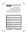
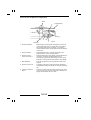
1 SAFETY INFORMATION
(ALL Areas)
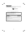
CAUTION
Danger of explosion if battery is incorrectly replaced.
Replace only with the same or equivalent type
recommended by the manufacturer.
Dispose of used batteries according
to the manufacturer’s instructions.
(Denmark only)
ADVARSEL!
Lithiumbatteri - Eksplosionsfare ved fejlagtig håndtering.
Udskiftning må kun ske med batteri
af samme fabrikat og type.
Levér det brugte batteri tilbage til leverandøren.
(Norway only)
ADVARSEL
Eksplosjonsfare ved feilaktig skifte av batteri.
Benytt samme batteritype eller en tilsvarende
type anbefalt av apparatfabrikanten.
Brukte batterier kasseres i henhold til fabrikantens
instruksjoner.
(Sweden only)
VARNING
Explosionsfara vid felaktigt batteribyte.
Använd samma batterityp eller en ekvivalent
typ som rekommenderas av apparattillverkaren.
Kassera använt batteri enligt fabrikantens
instruktion.
(Finland only)
VAROITUS
Paristo voi räjähtää, jos se on virheellisesti asennettu.
Vaihda paristo ainoastaan laitevalmistajan suosittelemaan
tyyppiin. Hävitä Käytetty paristo valmistajan ohjeiden
mukaisesti.
G-1
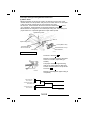
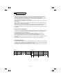
2 TECHNICAL HIGHLIGHTS
This copier has the following mechanical features.
◆ The original is aligned at the rear corner, while the copy paper is fed
through the center of the copier.
◆ Three fusing heater lamps are used, which enables the copier to
complete warming up in less than 5 minutes. (For details, see p. M-164.)
◆ All original size detecting sensors are fixed, enhancing measuring
accuracy. (For details, see p. M-54.)
* The copier becomes capable of detecting both the metric and inch
original sizes when equipped with the optional original size detecting
sensors.
◆ The paper take-up retry control minimizes the occurrence of paper
misfeeds. (For details, see p. M-124.)
The copier has the following control features.
◆ The watchdog (CPU overrun monitor) function monitors the operation of
the CPUs mounted in the copier and, if a CPU overrun is detected, it
automatically resets the faulty CPU, restarting the logic circuit and
mechanism. (For details, see p. M-11.)
◆ The malfunction bypass function minimizes downtime when the copier
develops a malfunction. (For details, see p. M-14.)
◆ The image stabilization system stabilizes the copy image. (For details,
see p. M-16.)
G-2
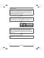
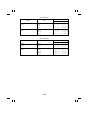
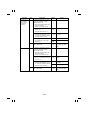
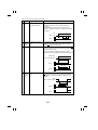
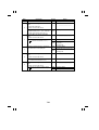
3 SPECIFICATIONS
TYPE
: Console
PLATEN
: Stationary
PHOTOCONDUCTOR
: Organic Photoconductor
COPYING SYSTEM
: Electrostatic dry powdered image transfer to plain paper
PAPER FEEDING
SYSTEM
: 4-way system
Multi Bypass Table: 50 sheets of
paper
1st and 2nd Drawer: Each holding
up to 500 sheets of paper
3rd Drawer: Holding up to 2,500
sheets of paper
EXPOSURE SYSTEM
: Mirror scanning, slit exposure
DEVELOPING SYSTEM
: New Micro-Toning system
CHARGING SYSTEM
: Double-wire DC negative corona with Scorotron system
IMAGE TRANSFER
SYSTEM
: Visible image transfer by means of a single-wire DC
negative corona with Corotron system
PAPER SEPARATING
SYSTEM
: Single-wire AC corona with Corotron system (AC plus
DC positive bias voltage) plus PC Drum Paper
Separator Fingers
OZONE REMOVAL
: By means of Ozone Filter
FUSING SYSTEM
: Heat Roller
PAPER DISCHARGING
SYSTEM
: Charge Neutralizing Brush
TYPES OF ORIGINALS
: Sheets, books, and other three-dimensional objects
weighing up to 3 kg or 6-1/2 lbs.
MAXIMUM ORIGINAL
SIZE
: A3 or 11" × 17" lengthwise
G-3
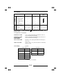
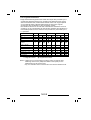
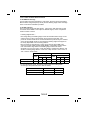
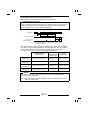
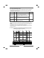
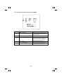
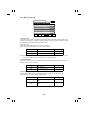
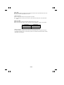
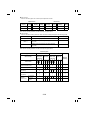
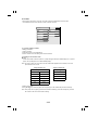
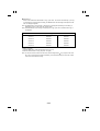
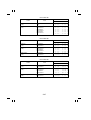
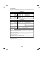
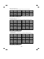
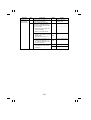
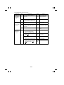
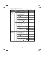
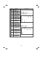
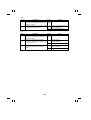
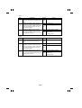
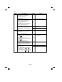
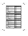
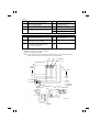
Dimensions
Medium
COPY MEDIUM:
Paper Source
1st to 2nd Drawer
3rd Drawer
Multi Bypass
Table
Plain paper
(60 to 90 g/m 2 )
O
O
O
Translucent paper
—
—
Transparencies
—
—
Thick paper (90 to
157 g/m 2)
—
—
Recycled paper
O
O
O
Maximum
(Width × Length)
297 × 432 mm
A4C
297 × 432 mm
Minimum
(Width × Length)
140 × 182 mm
8-1/2"×11"C
100 × 140 mm
O: Permissible —: Not permissible
sheets or less
L: Lengthwise, C: Crosswise
: Conditionally permissible ... 20
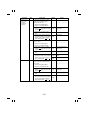
WARMING-UP TIME
: 5 min. or less (with ambient temperature of 23°C or
73°F and rated source voltage)
WARMING-UP TIME
AFTER ENERGY
SAVER MODE
: 30 sec. or less (with ambient temperature of 23°C or
73°F and rated source voltage)
AUTO CLEAR TIME
: Standard 1 min. (setting selectable from among 2, 3,
and 5 min.)
FIRST COPY TIME
: A4C or 8-1/2" × 11"C (Full size, fed from 1st Drawer):
3.8 sec. or less
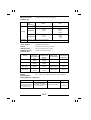
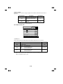
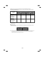
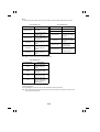
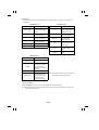
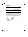
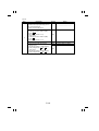
COPY SPEED
: Full size
Metric Area
Inch Area
Size
copies/min.
Size
copies/min
A3L
31
11" × 17"
31
B4L
40
8-1/2" × 11"L
50
A4L
47
8-1/2" × 11"C
60
A4C
60
B5L
52
B5C
60
L: Lengthwise; C: Crosswise
G-4
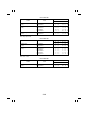
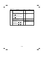
MULTIPLE COPIES
: 1 to 999 copies (count-down system)
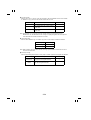
ZOOM RATIOS
Area
Mode
Full Size
Reduction
Fixed
Enlargement
Metric
Inch
×1.000
×1.000
×0.816
×0.707
×0.500
×0.785
×0.733
×0.647
×0.500
×2.000
×1.414
×1.154
×2.000
×1.545
×1.294
×1.214
Variable ×0.500 to ×2.000 (in 0.001 increments)
LENS
: Through Lens (F=5.6, f=215 mm)
LIGHT SOURCE
: Halogen frost tube lamp
FUSING
TEMPERATURE
: 190°C (in copy cycle and standby)
: 180°C (in Energy Saver mode)
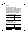
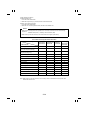
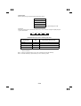
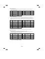
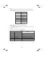
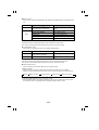
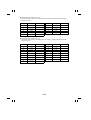
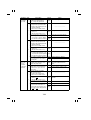
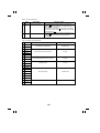
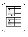
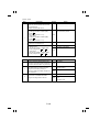
POWER/CURRENT
CONSUMPTION
: Copier with full set of options
Voltage
Exposure
Lamp (Rating)
Fusing Roller
Heater Lamp
(Rating)
Max. Power
Consumption
Power
Consumption
in Standby
115 V
90 V
220 W
115 V
900 W
1320 W
1070 W
120,127 V
90 V
220 W
120,127 V
900W
1370 W
1070 W
200~220 V
160 V
250 W
200/220 V
1040 W
1620~1790 W
1330 W
220~240 V
160 V
250 W
200/220 V
1040 W
1590~1740 W
1330 W
POWER
REQUIREMENTS
: 115V, 120V, 127V, 200V, 220V, 230V, 240V; 50/60 Hz
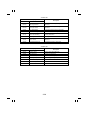
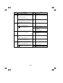
ENVIRONMENTAL CONDITIONS :
Temperature
Humidity
Ambient Illumination
Levelness
10 to 35°C
(50 to 95°F) with a
fluctuation of 10°C or
less per hour
15 to 85% RH with a
fluctuation of 20% RH
or less per hour
3,000 lux or less
1°
(1.75/100)
G-5
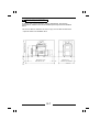
DIMENSIONS
: Copier only
Width .... 746 mm or 29-1/4"
Depth .... 720 mm or 28-1/4"
Height ... 969 mm or 38-1/4"
WEIGHT
: 195 kg or 430 lbs.
(including the Duplexing Document Feeder and PC Drum)
STANDARD
ACCESSORIES
: Duplexing Document Feeder AFR-9, Toner Collecting
Bottle, Operator’s Manual, Starter, PC Drum
OPTIONS
: Large Capacity Cassette C-302
Exit Tray
20-Bin Sorter S-206
Staple Sorter ST-207
Data Controller DT-103
Data Controller D-102
Plug-In Counter
Bias Seal
Original Cover
G-6
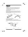
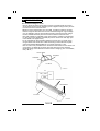
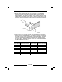
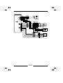
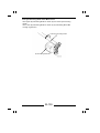
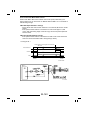
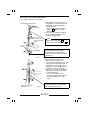
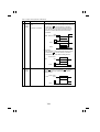
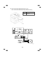
4 SPACE REQUIREMENTS
To ensure easy copier operation, supply replacement, and service
maintenance, adhere to the recommended space requirements detailed
below.
* Be sure to allow a clearance of 150 mm (6") or more at the back of the
300 mm or 11-3/4"
1335 mm or 52-1/2"
copier as there is a ventilation duct.
150 mm or 6"
200 mm or 7-3/4"
2844 mm or 112"
1342 mm or 52-3/4"
1075O127CA
G-7
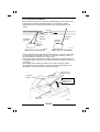
5 PRECAUTIONS FOR INSTALLATION
Installation Site
To ensure safety and utmost performance of the copier, the copier should
NOT be used in a place:
● Where it will be subjected to extremely high or low temperature or
humidity.
● Which is exposed to direct sunlight.
● Which is in the direct air stream of an air conditioner, heater or
ventilator.
● Which puts the operator in the direct stream of exhaust from the copier.
● Which has poor ventilation.
● Where ammonia gas might be generated.
● Which does not have a stable, level floor.
● Where it will be subject to sudden fluctuations in either temperature or
humidity. If a cold room is quickly heated, condensation forms inside
the copier, resulting in blank spots in the copy.
● Which is near any kind of heating device.
● Where it may be splashed with water.
● Which is dirty or where it will receive undue vibration.
● Which is near volatile flammables or curtains.
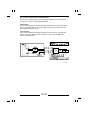
Power Source
Use an outlet with a capacity of 115/120/127V, 12A or more, or
200/220/230/240V, 8.5A or more.
● If any other electrical equipment is sourced from the same power
outlet, make sure that the capacity of the outlet is not exceeded.
● Use a power source with little voltage fluctuation.
● Never connect by means of a multiple socket any other appliances or
machines to the outlet being used for the copier.
● Make the following checks at frequent intervals:
• Is the power plug abnormally hot?
• Are there any cracks or scrapes in the cord?
• Has the power plug been inserted fully into the outlet?
• Does something, including the copier itself, ride on the power cord?
● Ensure that the copier does not ride on the power cord or
communications cable of other electrical equipment, and that it does
not become wedged into or underneath the mechanism.
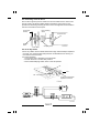
Grounding
To prevent receiving electrical shocks in the case of electrical leakage,
always ground the copier.
● Connect the grounding wire to:
• The ground terminal of the outlet.
• A grounding contact which complies with the local electrical standards.
● Never connect the grounding wire to a gas pipe, the grounding wire for
a telephone, or a water pipe.
G-8
6 PRECAUTIONS FOR USE
To ensure that the copier is used in an optimum condition, observe the
following precautions.
● Never place a heavy object on the copier or subject the copier to
shocks.
● Insert the power plug all the way into the outlet.
● Do not attempt to remove any panel or cover which is secured while the
copier is making copies.
● Do not turn OFF the Power Switch while the copier is making copies.
● Provide good ventilation when making a large number of copies
continuously.
● Never use flammable sprays near the copier.
● If the copier becomes inordinately hot or produces abnormal noise, turn
it OFF and unplug it.
● Do not turn ON the Power Switch at the same time when you plug the
power cord into the outlet.
● When unplugging the power cord, do not pull on the cord; hold the plug
and pull it out.
● Do not bring any magnetized object near the copier.
● Do not place a vase or vessel containing water on the copier.
● Be sure to turn OFF the Power Switch at the end of the workday or
upon power failure.
● Use care not to drop paper clips, staples, or other small pieces of metal
into the copier.
Operating Environment
The operating environmental requirements of the copier are as follows.
• Temperature: 10°C to 35°C (50 to 95°F) with a fluctuation of 10°C per
hour
• Humidity: 15% to 85% RH with a fluctuation of 20% RH per hour
Power Requirements
The power source voltage requirements are as follows.
• Voltage Fluctuation:
AC115/120/127/200/220/230/240V
±10% (Copying performance assured)
−15% (Paper feeding performance
assured)
• Frequency Fluctuation:
50/60 Hz ±0.3%
G-9
7 HANDLING OF THE CONSUMABLES
Before using any consumables, always read the label on its container
carefully.
● Use the right toner. The applicable copier model name is indicated on
the Toner Bottle.
● Paper is apt to be easily damaged by dampness. To prevent
absorption of moisture, store paper, which has been removed from its
wrapper but not loaded into the Drawer, in a sealed plastic bag in a
cool, dark place.
● Keep consumables out of the reach of children.
● Do not touch the PC Drum with bare hands.
● Store the paper, toner, and other consumables in a place free from
direct sunlight and away from any heating apparatus.
● The same sized paper is of two kinds, short grain and long grain. Short
grain paper should only be fed through the copier crosswise, long grain
paper should only be fed lengthwise.
● If your hands become soiled with toner, wash them with soap and
water immediately.
● Do not throw away any used consumables (PC Drum, starter, toner,
etc.). They are to be collected.
NOTE
Do not burn, bury in the ground, or throw into the water any
consumables (PC Drum, starter, toner, etc.).
G-10
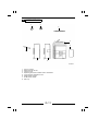
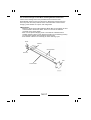
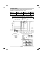
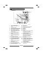
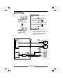
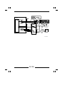
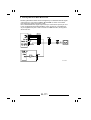
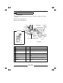
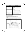
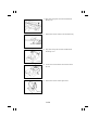
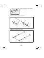
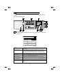
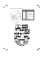
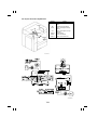
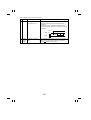
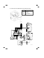
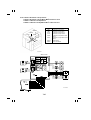
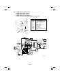
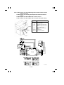
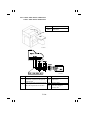
8 SYSTEM OPTIONS
1
2
3
4
5
8
7
1.
2.
3.
4.
5.
6.
7.
8.
6
Plug-In Counter
Data Controller D-102
Original Cover
Duplexing Document Feeder AFR-9 <Standard>
Large Capacity Cassette C-302
Staple Sorter ST-207
20-Bin Sorter S-206
Exit Tray
G-11
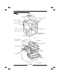
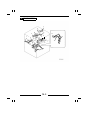
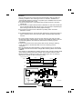
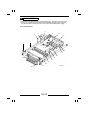
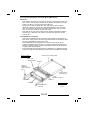
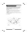
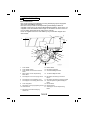
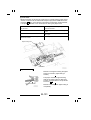
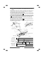
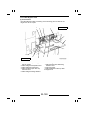
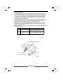
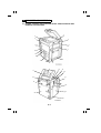
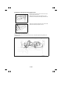
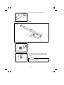
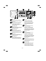
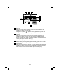
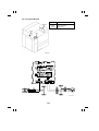
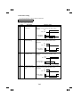
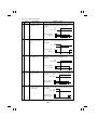
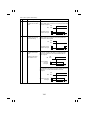
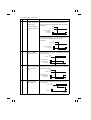
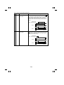
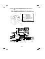
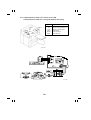
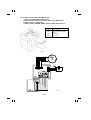
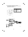
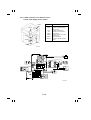
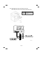
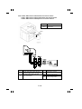
9 PARTS IDENTIFICATION
Control Panel
Manual Bypass Table
Upper Front Door
Lower Front Door
Power Switch
1st Drawer
2nd Drawer
Right Door Lock
Release Lever
Total Counter
Display Contrast
Control Knob
Toner Bottle
Toner Bottle Holder
Lock Release Lever
PC Unit
Fusing Unit
Duplex Unit
G-12
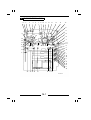
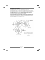
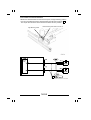
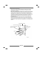
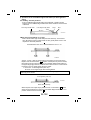
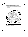
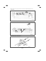
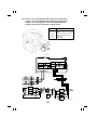
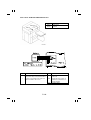
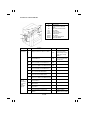
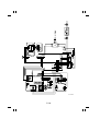
1 CROSS-SECTIONAL VIEW
1 2
3
5
4
6
7
9
10
11
12
14
13
15
16
21
17
D
19
27 28
36
8
18
29
35
34
A
25
30
E
32
33
31
26
24 23 22 20
B
C
37
44
F
I
J
45
46
K
L
47
48
M
N
49
38
39 G 40
42 H
41
43
1075M096AA
M-1
1. Optical Section Cooling Fan
Motor M17
2. 3rd Mirror
3. 2nd Mirror
4. 1st Mirror
5. Exposure Lamp LA1
6. Fusing Unit Ventilation Fan
Motor M8
7. Lens
8. Pre-Cleaning Erase Lamp LA5
9. Cleaning Blade
10. Main Erase Lamp LA2
11. PC Drum Charge Corona
12. 6th Mirror
13. 4th Mirror
14. Image Erase Lamp LA3
15. 5th Mirror
16. Toner Suction Fan Motor M20
17. Developing Unit
18. Manual Bypass Take-Up Roll
19. Transport Roller
20. Synchronizing Roller
21. Pre-Image Transfer Erase
Lamp LA4
22. 1st and 2nd Sleeve/Magnet
Rollers
23. Image Transfer/Paper
Separator Coronas
24. PC Drum
25. PC Drum Paper Separator
Finger
26. Suction Unit
27. Fusing Unit
28. Web Roller
29. Upper Fusing Roller Main
Heater Lamp H1
30. Upper Fusing Roller Sub
Heater Lamp H2
31. Lower Fusing Roller Heater
Lamp H3
32. Lower Fusing Paper Separator
Finger
33. Upper Fusing Paper Separator
Finger
34.
35.
36.
37.
38.
39.
40.
41.
42.
43.
44.
45.
46.
47.
48.
49.
Fusing Unit Transport Roller
Exit/Duplexing Switching Plate
Paper Exit Roller
Turnover/Paddles Roller
Turnover Drive Roller
Ventilation Fan Motor M19
Gate 2 Transport Roller
Gate 1 Transport Roller
Duplex Paper Take-Up Roll
Duplex Vertical Transport Roller
Vertical Transport Roller 1
1st Drawer Paper Take-Up
Section
Vertical Transport Roller 2
2nd Drawer Paper Take-Up
Section
Vertical Transport Roller 3
3rd Drawer Paper Take-Up
Section
- Misfeed Sensors A. Manual Feed Paper Empty
Sensor PC28
B. Transport Roller Sensor PC26
C. Paper Leading Edge Sensor
PC27
D. Paper Exit Sensor PC36
E. Transport Feed Sensor PC37
F. Duplex Unit Turnover Path
Sensor PC39
G. Duplex Unit Paper Entry
Sensor PC38
H. Duplex Unit Paper Take-Up
Sensor PC40
I. Vertical Transport Sensor 1
PC10
J. 1st Drawer Paper Take-Up
Sensor PC6
K. Vertical Transport Sensor 2
PC11
L. 2nd Drawer Paper Take-Up
Sensor PC7
M. Vertical Transport Sensor 3
PC12
N. 3rd Drawer Paper Take-Up
Sensor PC8
M-2
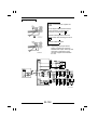
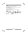
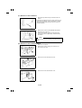
2 COPY PROCESS
2. DRUM
CHARGING
3. EXPOSURE
4. IMAGE ERASE
12. MAIN ERASE
11. CLEANING
1. PC DRUM
10. PRE-CLEANING ERASE
15.
EXIT/DUPLEX
SWITCHING
14. FUSING
16. TURNOVER
13. TRANSPORT
5. DEVELOPING
6. PRE-IMAGE TRANSFER ERASE
9. PAPER
SEPARATION
17. DUPLEX UNIT
8. IMAGE
TRANSFER
7. MULTI BYPASS
TABLE
7. PAPER FEEDING
1. PC Drum
The PC Drum is an aluminum cylinder coated with a photosensitive semiconductor.
It is used as the medium on which a visible developed image of the original is
formed.
(For more details, see p. M-25.)
2. Drum Charging
The PC Drum Charge Corona Unit is equipped with two corona wires and Scorotron
Grids to deposit a uniform negative charge across the entire surface of the PC
Drum.
(For more details, see p. M-28.)
3. Exposure
Light from the Exposure Lamp reflected off the original is guided to the surface of
the PC Drum and reduces the level of the negative charges, thereby forming an
electrostatic latent image.
(For more details, see p. M-34.)
4. Image Erase
Any areas of charge which are not to be developed are neutralized by lighting up
LEDs.
(For more details, see p. M-62.)
5. Developing
Toner positively charged in the Developer Mixing Chamber is attracted onto the
electrostatic latent image changing it to a visible, developed image.
(For more details, see p. M-69.)
6. Pre-Image Transfer Erase
Light from the Pre-Image Transfer Erase Lamp striking the surface of the PC Drum
improves image transfer and paper separation efficiency.
(For more details, see p. M-93.)
M-3
7. Paper Feeding
Paper is fed from each drawer or Multi Bypass Table.
(For more details, see p. M-95.)
8. Image Transfer
The single-wire Image Transfer Corona Unit applies a DC negative corona emission
to the underside of the paper, thereby attracting toner onto the surface of the paper.
(For more details, see p. M-143.)
9. Paper Separation
The single-wire Paper Separator Corona Unit applies an AC corona emission [AC +
DC(+) bias voltage] to the underside of the paper to neutralize the paper.
(For more details, see p. M-143.)
In addition, mechanical paper separation is provided by the three PC Drum Paper
Separator Fingers.
(For more details, see p. M-155.)
10. Pre-Cleaning Erase
Light from the Pre-Cleaning Erase Lamp striking the surface of the PC Drum
reduces surface potential, thereby preventing toner accumulated on the back of the
Cleaning Blade from sticking to the surface of the PC Drum.
(For more details, see p. M-154.)
11. Cleaning
Residual toner on the surface of the PC Drum is scraped off by the Cleaning Blade
and conveyed to the Toner Collecting Bottle.
(For more details, see p. M-150.)
12. Main Erase
Light from the Main Erase Lamp neutralizes any surface potential remaining on the
surface of the PC Drum after cleaning.
(For more details, see p. M-160.)
13. Transport
The paper is fed to the Fusing Unit by the Suction Belts.
(For more details, see p. M-162.)
14. Fusing
The developed image is permanently fused to the paper by a combination of heat
and pressure applied by the Upper and Lower Fusing Rollers.
(For more details, see p. M-164.)
15. Exit/Duplex Switching
After the fusing process the paper is either fed out onto the Exit Tray or down into
the turnover mechanism of the Duplex Unit.
(For more details, see p. M-178.)
16. Turnover
The 1-sided copy is turned over and fed into the Duplex Unit.
(For more details, see p. M-181.)
17. Duplex Unit
The 1-sided copies are stored and then taken up one by one for the second copy
cycle.
(For more details, see p. M-186.)
M-4
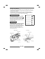
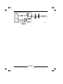
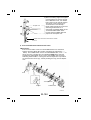
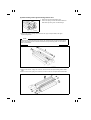
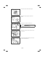
3 DRIVE SYSTEM
7
C
B
6
4
1
2
A
G
9
D
3 5
11
12
13
8
15
10
E
F
14
M-5
16
A = Fusing Motor M6: Drives the Fusing Unit, Paper Exit Roller, and Suction
Belts.
1. Paper Exit Roller drive pulley
2. Fusing Unit drive gear
3. Suction Belt drive gear
B = PC Drum Drive Motor M5: Drives the PC Drum, Developing Unit, and
Toner Conveying Screw.
4. Toner Conveying Screw drive gear
5. PC Drum drive coupling pawl A
6. Developing Unit drive coupling gear 2
C = Scanner Motor M11: Drives the Scanner and 2nd/3rd Mirrors Carriage.
7. Scanner drive pulley
D = Transport Motor M3: Drives the Transport Roller and Multi Bypass
Take-Up mechanism.
8. Multi Bypass Take-Up drive gear
9. Multi Feed Paper Take-Up Clutch CL5
10. Transport Roller drive gear
E = Synchronizing Motor M4: Drives the Synchronizing Roller
11. Synchronizing Roller drive gear
F = Paper Take-Up Motor M1: Drivers the Paper Take-Up mechanism and
the Duplex Take-Up mechanism.
12. Duplex Take-Up mechanism drive gear
13. Duplex Unit Paper Take-Up Clutch CL6
14. Paper Take-Up Clutch for drawers CL1 to 3
G = Vertical Transport Motor M2 = Drives the Vertical Transport Rollers and
Duplex Vertical Transport Rollers.
15. Vertical Transport Roller drive gear
16. Duplex Vertical Transport Roller drive gear
M-6
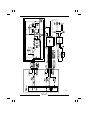
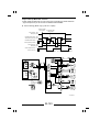
4 SEQUENTIAL EXPLANATION
A The power cord is plugged into the outlet.
ON
ON
ON
DC Power Supply 1 PU2 outputs DC24V for dehumidifiers.
* Only when Drum
Drum Dry Heater H4, Lower Paper
Dehumidifying Heater H5, and Upper Dehumidifying Switch
S9 and Paper
Paper Dehumidifying Heater H7
Developing Unit Dehumidifying Heater Dehumidifying Switch
S10 are ON.
H6
B Power Switch S1 is turned ON.
OFF
H4, H5, H7, H6
ON
PU2 outputs DC24V and DC5V.
ON
DC Power Supply Board PWB-C outputs
DC24V. (DC24V line: ON)
ON
ON
ON
Master Board PWB-A outputs DC4.7V and DC12V.
Control panel display
Suction Fan Motor M18 turns at half speed.
Approx. 1 sec.
ON
Upper Fusing Roller Main/Sub Heater Lamp H1/H2
The Lens is detected at the home position.
The Mirror is detected at the
home position.
The Scanner makes its initial motion.
ON
For details, see
The Lens is detected at the
OPTICAL SECTION.
full size position.
The Mirror is detected at
the full size position.
PC Drum Charge Wire Cleaning Motor / Image
Transfer/Paper Separator Charge Wire Cleaning Motor
M21/M22
Approx.
24 sec.
OFF
M21, M22: Cleaner makes one round trip to
clean the wire and stops.
One-Shot Correction mode (For details, see
p. M-24.)
The surface temperature of the Upper Fusing Roller reaches 170°C.
ON
Fusing Motor M6 starts predrive.
➀
M-7
➀
* Timing depends on the surface temperature of the
After 85 sec. or
40 sec. or 5 sec.
OFF
M6
ON
Fusing Unit
Upper Fusing Roller and the difference in surface
temperature between the Upper and Lower Fusing
Rollers when S1 is turned ON.
(For details, see p. M-175.)
Ventilation Fan Motor M8
= The following sequence is when making a single copy in full size on A4
crosswise fed from the 1st Drawer. =
C
The Start Key is pressed.
(A4 crosswise paper fed from 1st Drawer, full size, single copy cycle)
ON
M6
Approx.
5 sec.
ON
ON
ON
PC Drum Drive Motor M5
Developing Bias
Optical Section Cooling Fan Motor / Ventilation Fan
Motor / Toner Suction Fan Motor / Power Supply
Unit Cooling Fan Motor M17/M19/M20/M29
Suction Fan Motor M18 turns at full speed.
Approx. 250 msec. ON Image Transfer/Paper
Separator Coronas
Exposure Lamp / Image
Erase Lamp LA1/LA3
Approx. 350 msec. ON Main Erase Lamp LA2
Approx. 400 msec. ON PC Drum Charge Corona
Approx. 450 msec. ON Pre-Image Transfer Erase
Lamp / Pre-Cleaning Erase
Lamp LA4/LA5
ON
Paper Take-Up Motor / Vertical Transport Motor / Transport
Motor M1/M2/M3
ON
1st Drawer Paper Take-Up Clutch CL1
Vertical Transport Sensor 1 PC10 is blocked ( L ).
Approx. 60 msec.
OFF
CL1, M1
Paper Leading Edge Sensor PC27 is blocked ( L ).
Approx. 50 msec.
OFF
M2, M3
M-8
D
PWB-A outputs a LOW SCAN signal to Scanner Control
Processor Board PWB-J.
The Scanner starts a scan motion.
A LOW Image Leading Edge signal is input to PWB-A.
ON
LA3
OFF
Approx. 65 msec.
LA3 ... Leading edge erase
E PWB-J outputs a LOW TRON signal to PWB-A.
ON
M3/M4
Approx. 120 msec.
ON
Separator Finger Solenoid SL6
Approx. 280 msec.
OFF
SL6
F PWB-J outputs a LOW SCEND signal to PWB-A.
Approx. 200 msec., the SCEND signal goes HIGH.
SCAN signal: H ... The Scanner stops and starts a return motion.
Scanner Reference Position Sensor PC1 is blocked ( L ).
OFF
Approx. 50 msec.
LA1
Approx. 80 msec. OFF PC Drum Charge Corona
Approx. 570 msec. OFF Image Transfer/Paper Separator Coronas
Approx. 690 msec. OFF LA4/LA5
Approx. 1,050 msec. OFF LA2/LA3
M5
Approx. 1,350 msec. OFF Developing Bias
M-9
G
The trailing edge of the paper moves past Transport Roller Sensor PC26
(unblocked: H ).
Approx. 144 msec.
H
M3
The trailing edge of the paper moves past Paper Leading Edge Sensor
PC27 (unblocked: H ).
Approx. 90 msec.
I
OFF
OFF
Synchronizing Motor M4
The trailing edge of the paper moves past Paper Exit Sensor PC36
(unblocked: H ).
Approx. 600 msec.
Approx.
4,600 msec.
OFF
OFF
M6
M17/M19/M20/M29
M18 turns at half speed.
M-10
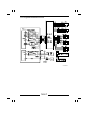
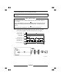
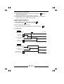
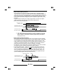
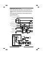
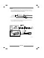
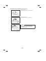
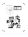
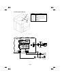
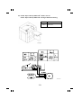
5 WATCHDOG (CPU OVERRUN MONITOR) FUNCTION
5-1. Overview
The watchdog function monitors whether any of the CPUs mounted in the
copier overrun. If this function detects that a CPU overruns, the copier
automatically resets the CPU, thereby restarting the logic circuit and
mechanism.
Even if a copier CPU operates erratically due to electrical noise, therefore,
the copier is able to recover from the faulty condition so that the number of
visits made by the Technical Representative for CPU overrun can be
minimized.
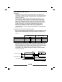
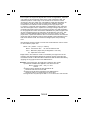
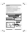
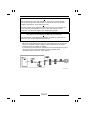
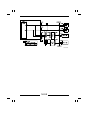
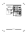
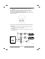
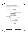
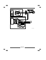
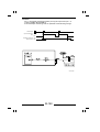
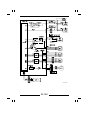
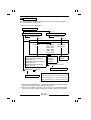
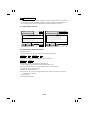
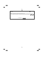
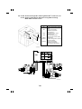
5-2. Configuration
The copier has three printed-circuit boards each on which a CPU is mounted:
* SCP (Scanner Control Processor) Board PWB-J that controls the optical
system;
* MSC (Macro System Controller) Board PWB-B that controls the control
panel and system; and,
* Master Board PWB-A.
In addition to these, each of the control boards for the Data Controller,
Duplexing Document Feeder, and Sorter/Staple Sorter is equipped with a
CPU.
The watchdog functions are summarized as follows:
* Each of the copier CPUs monitors whether or not it overruns.
* The PWB-B monitors the communications conditions of the CPUs in the
Duplexing Document Feeder and Data Controller.
* The PWB-A monitors the communications conditions of the CPUs in the
Sorter and Staple Sorter.
Data Controller
Duplexing
Document Feeder
Control Board
Control Board (PWB-A)
Copier
SCP Board PWB-J
Sorter, Staple Sorter
MSC Board PWB-B
Control Board (PWB-A)
Master Board PWB-A
= Board on which a
CPU is mounted
M-11
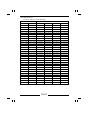
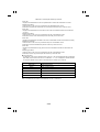
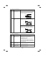
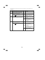
5-3. Watchdog Function Post-Processing
The following processing is performed if a faulty condition is detected in the
CPU. The Watchdog Counter available from the Tech. Rep. mode allows the
Technical Representative to check if any faulty condition has occurred in the
CPU. For details, see SWITCHES ON PWBs.
Faulty CPU
Processing (in Standby)
Processing
(during Copy Cycle)
Copier
1 : The CPU is automatically reset (i.e.,
shutting down power to all CPUs
including those in the options) as
soon as a faulty CPU is detected.
1: Same as 1 on the left.
2: Since the paper is left
inside the copier, the
copier detects a misfed
sheet of paper or two
when power is turned
ON again. If the MSC
CPU is faulty, however,
all paper in line for the
exit will be ejected and
all paper headed to the
duplex will be stored,
before restarting the
CPU.
Sorter,
Staple Sorter
1 : When the CPU malfunctions, the
communication to Master Board
PWB-A of the copier is cut off or
faulty data is transmitted to the
PWB-A.
2 : The PWB-A detects that the CPU of
the Sorter or Staple Sorter is faulty.
3 : The PWB-A notifies MSC Board
PWB-B that the CPU of the Sorter or
Staple Sorter is faulty.
4 : As commanded by the PWB-B,
Option Relays RY3C and 4C are
turned OFF and ON to restart the
option.
5 : The communication line from the
CPU of the Sorter or Staple Sorter to
PWB-A is recovered.
6 : PWB-A notifies PWB-B that the CPU
of the Sorter or Staple Sorter has
recovered from the faulty condition.
1 : Same as 1, 2, and 3 on
the left.
2 : The paper take-up
sequence is stopped.
3 : All sheets of paper
being fed through the
copier are fed out of
the copier.
4 : Same as 4, 5, and 6 on
the left.
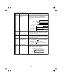
M-12
Faulty CPU
Other than
above
Processing (in Standby)
1 : When the CPU malfunctions, the
communication to MSC Board
PWB-B of the copier is cut off or
faulty data is transmitted to the
PWB-B.
2 : PWB-B detects that the CPU
malfunctions.
3 : As commanded by the PWB-B,
Option Relays RY3C and 4C are
turned OFF and ON to restart the
option.
4 : The communication line from the
CPU to PWB-B is recovered.
5 : PWB-B detects that the CPU has
recovered from the faulty condition.
M-13
Processing
(during Copy Cycle)
1 : Same as 1 and 2 on
the left.
2 : The paper take-up
sequence is stopped.
3 : All sheets of paper
being fed through the
copier are fed out of
the copier.
4 : Same as 3, 4, and 5 on
the left.
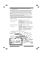
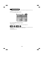
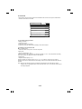
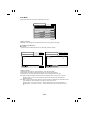
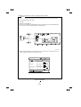
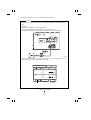
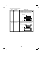
6 MALFUNCTION BYPASS FUNCTION
6-1. Overview of the Malfunction Bypass Function
• When a malfunction occurs in the copier, the malfunction bypass function
permits the copier to continue operating if that malfunction is any of the
predefined candidates for isolated malfunctions and if it will not affect the
current copying operations.
• If a copying function involving the isolated malfunction is selected, the
message "Selected mode can’t be used." appears on the Touch Panel and
the copier rejects that function.
• A dot mark " " appears at the location on the Touch Panel shown below
when the malfunction bypass function is activated. The isolated
malfunctions which have so far occurred can be viewed (malfunction codes
are shown; graphic symbols are shown for the Sorter-related malfunctions)
by selecting the "Machine status" function on the Tech. Rep. mode menu
screen. (For details, see SWITCHES ON PWBs.)
Auxiliary
Finishing
Orig.
Ready to copy.
Copy
Basics
1
Auto Expo.
x1.000
Auto Paper
Exposure
Zoom
Paper
1075M158CA
Dot mark
• Up to five isolated malfunctions are shown. When a sixth isolated
malfunction occurs, the copier considers it as a normal malfunction,
prompting a Tech. Rep. call. (The sixth malfunction is shown on the Touch
Panel.)
M-14
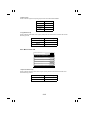
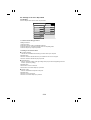
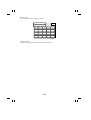
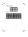
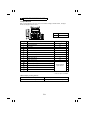
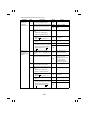
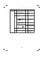
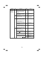
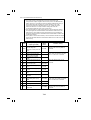
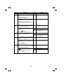
6-2. Candidates for Isolated Malfunctions
● Copier-Related
Item
1 1st Drawer
Malfunction Code
C0920/C0924 *1. C0921~23/C0926
2 2nd Drawer
C0910/C0914 *2. C0911~13/C0916
3 3rd Drawer
C0990~96/C0998~9C/C0351/C0352/C0F79
4 Duplex Unit
C0d00/C0d20/C0d50/C0353
5 Auto Paper, Auto Size
C0F02/C0FE1~C0FFF
6 AIDC
C0F20~23
*1, *2 : For Inch Areas only
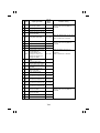
● Cabinet/Sorter-Related
7
Large Capacity
Cassette (C-302)
C09C0/C09C2/C0354/C0374
8
Sorting (S-206,
ST-207)
C0b10~13/C0b60~64
9 Stapling (ST-207)
C0b10~13/C0b30/C0b51/C0b60~64
10 Punching (ST-207)
C0b70/C0b71
* The isolated malfunctions as they are related to the Sorter are shown by
graphic symbols as shown below. For C0b10 to 13, C0b51, and C0b70,
they are handled as isolated malfunctions only when detected during initial
motion. They are normal malfunctions if they occur during a copy cycle.
C0b10~13/30/60~64 :
1134M071AA
C0b51
:
1134M072AA
C0b70, 71
:
1134M073AA
M-15
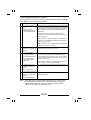
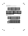
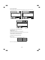
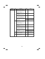
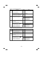
7 IMAGE STABILIZATION SYSTEM
7-1. Overview of the Image Stabilization System
◆ The following image stabilization controls are provided to ensure
stabilized copy image.
Item
Initial
Setting
Quality
Image
density,
gradation
Purpose
To make an initial
adjustment of the
toner-to-carrier
ratio (T/C) control
level and optimum
Exposure Lamp
voltage using the
F5 operation.
Image
density
To compensate for
any drop in image
density due to a
deteriorating PC
Drum.
Gradation
To compensate for
any drop in the
intensity of LA1
light due to a
contaminated
optical system.
Regular
Correction
To keep a given
Foggy
T/C of the
background developer in the
Developer Mixing
Chamber.
Control
• After making the variation adjustment
and contamination correction for the
AIDC Sensor, the copier produces a
solid-black and halftone pattern and,
through AIDC Sensor control, sets
the initial values for the T/C control
level and optimum Exposure Lamp
voltage.
• After making the AIDC Sensor
contamination correction, the copier
produces a solid-black pattern and,
through AIDC Sensor control, corrects
the T/C control level.
• The copier corrects the grid voltage
whenever the PC Drum has turned for
a given period of time.
• After making the AIDC Sensor
contamination correction, the copier
produces a halftone pattern and,
through AIDC Sensor control, corrects
the optimum Exposure Lamp voltage.
• The copier corrects the optimum
Exposure Lamp voltage whenever the
PC Drum has turned for a given
period of time.
• The copier provides toner
replenishing control through ATDC
Sensor control. (*1)
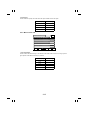
M-16
Item
Quality
Purpose
Control
One-Shot
Correction
Image
(When the
density,
Power
gradation
Switch is
turned ON)
To compensate for
any drop in surface
potential of the PC
Drum when the Power
Switch is turned ON in
the morning.
• After making the AIDC Sensor
contamination correction, the
copier produces a halftone
pattern and, through AIDC
Sensor control, corrects the
optimum Exposure Lamp voltage.
Correction
Image
for Faulty
density,
AIDC
gradation
Sensor
To compensate for
image density and
gradation aggravated
by a faulty AIDC
Sensor.
• The copier corrects the grid
voltage and optimum Exposure
Lamp voltage according to the
time over which the PC Drum
has turned.
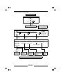
*1: See pp. M-77 of "DEVELOPMENT UNIT."
(According to Halftone Pattern Density)
Exposure Lamp Voltage Setting/Correction
Grid Voltage
Correction
Toner Replenishing
Rotation
Time
PC Drum
AIDC Sensor
ATDC
Sensor
T/C Control Level
Setting/Correction
(According to Solid-Black Pattern Density)
1075M101AA
M-17
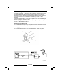
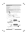
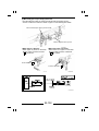
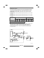
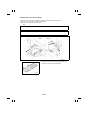
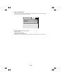
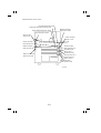
7-2. AIDC Sensor
To provide image stabilization control, this copier has AIDC Sensor UN9
fitted to the Cleaning Unit of the PC Unit. The sensor is used to detect the
toner density and background level on the PC Drum.
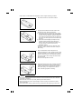
Theory of Operation
1. The UN9’s LED projects approx. 940-nm infrared light onto the surface
of the PC Drum.
2. The UN9’s phototransistor detects the amount of light reflected back.
3. The phototransistor outputs a voltage corresponding to the intensity of
the light reflected back.
Output GND
LED Power Supply
PC Drum Surface
Toner Density
Reflected Light
Output
High
Small
High
Low
Large
Low
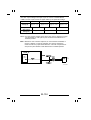
The AIDC Sensor LED is turned ON or OFF by the pulse signal output from
pin 13 of IC1A on Master Board PWB-A. The intensity of the light emitted by
the LED is controlled by varying the pulse width as shown below.
Pulse Width
IC1A-13
AIDC Sensor
LED
OFF
OFF
ON
Light Amount : Small
ON
ON
ON
OFF
Light Amount : Large
1075T184CA
M-18
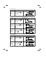
7-3. AIDC Sensor Control
◆ There are five processes performed as the AIDC Sensor control:
➀ AIDC Sensor variation adjustment
➁ AIDC Sensor contamination correction
➂ T/C control level setting (correction)
➃ Optimum Exposure Lamp
voltage setting (correction)
➄ AE Sensor gain adjustment
◆ Control of Each Process
➀ AIDC Sensor Variation Adjustment
This adjustment corrects part-to-part variations in the AIDC Sensor
(installation, sensitivity, deterioration, etc.). Pin 79 of IC1A on Master
Board PWB-A receives the output from the AIDC Sensor and from the
4-bit analog switch. The AIDC Sensor variations are corrected by
selecting the output of the 4-bit analog switch (i.e., changing the load
resistance). The 4-bit analog switch output is variable in 16 different
steps.
Control
The AIDC Sensor LED is turned ON to illuminate the erased surface on
the PC Drum.
The maximum 4-bit analog switch output is selected (i.e., the minimum
load resistance).
The sensor LED is illuminated with its maximum intensity.
Repeated
The input to pin 79 of IC1A at this time is sampled.
The sensor LED is illuminated with its minimum intensity.
The input to pin 79 of IC1A at this time is sampled. ... A
The 4-bit analog switch output is switched one step.
The 4-bit analog switch position is fixed when the voltage of A exceeds
1.1V for the first time.
➁ AIDC Sensor Contamination Correction
If the Sensor is dirty with toner, it results in an error being produced in
the AIDC Sensor output value. The intensity of the AIDC Sensor LED
light is therefore varied.
Control
The AIDC Sensor LED is turned ON to illuminate the erased surface on
the PC Drum.
The input to pin 79 of IC1A at this time is sampled.
The intensity of the AIDC Sensor LED light is varied so that the above
voltage becomes 1.0V. The pulse signal (pulse width) is selected when
the voltage is more than 1.0V and its deviation from 1.0V is the
smallest.
M-19
1075C50MAA
M-20
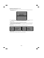
➂ T/C Control Level Setting (Correction)
The copier produces a solid-black pattern on the PC Drum and the AIDC
Sensor reads the image density (ID) of the pattern. If the ID reading is
found to fall outside the specified range, the copier increases or
decreases the T/C control level by 0.5%.
Control
The intensity of the AIDC Sensor LED light is set to a level three times
as strong as the normal one and grid voltage (V G) is output at a level
45V lower than usual.
With the Exposure Lamp turned OFF, the Image Erase Lamp is kept
OFF for a given period of time to produce a solid-black pattern.
The input to pin 79 of IC1A at this time is sampled. ... A
The AIDC Sensor LED light intensity and VG are returned to the normal
level.
The T/C control level is set as follows according to the voltage of A.
Voltage A
T/C Control Level
4.3V or higher 0.5% lower
4.1 to 4.3V
As is (5% if upon setting-up)
4.1V or lower
0.5% higher (Auxiliary toner replenishing is carried out for
about 60 sec. upon F5 operation.)
➃ Optimum Exposure Lamp Voltage Setting (Correction)
The copier produces a halftone pattern on the PC Drum and the AIDC
Sensor reads the ID of the pattern. The copier adjusts the Exposure
Lamp voltage (VL) to obtain a good ID.
The following four different types of controls are provided for the
optimum Exposure Lamp voltage correction. Control (3) is not provided if
the input to pin 79 of IC1A is outside the specified range (3.85 to 4.45V)
as checked through the T/C control level setting performed immediately
before control (3).
(1) The optimum Exposure Lamp voltage is adjusted at the initial setup or
when the first F5 operation is run after the PC Drum has been
replaced with a new one (the PC Drum counter has been cleared).
(The adjustment value should fall within the range 50 to 82V, in 1V
increments.)
Control
LA1 is turned ON to illuminate the halftone patch on the back of the
Original Width Scale and LA3 is kept OFF for a given period of time to
produce a halftone pattern.
The input to pin 79 of IC1A at this time is sampled. ... A
VL is varied so that voltage A becomes 1.6V or as near 1.6V as
possible.
M-21
(2) A correction is made when the second or subsequent F5 test
operation is run after the Exposure Lamp has been cleaned or "Exp.
Lamp Manual Adj." setting of Tech. Rep. Choice changed. [The
correction should be in the range between +2 and −4V with respect to
the optimum Exposure Lamp voltage set in (1).]
Control
The Exposure Lamp voltage (VL) is set at a value set in (1) minus 4V.
LA1 is turned ON to illuminate the halftone patch on the back of the
Original Width Scale and LA3 is kept OFF for a given period of time to
produce a halftone pattern.
The input to pin 79 of IC1A at this time is sampled. ... A
VL is increased 1V at a time so that voltage A becomes 1.6V or as near
1.6V as possible.
(3) A correction is made of the Exposure Lamp voltage when the Power
Switch is turned ON first thing in the morning to compensate for any
drop in the surface potential of the PC Drum in the morning (One-shot
correction).
(4) A correction is made to compensate for any drop in the intensity of
LA1 light occurring due to a contaminated optical system. This is done
for every 200 copies made after the Power Switch has been turned
ON.
Control for (3) or (4)
With the Exposure Lamp voltage set by (1) or (2) :
LA1 is turned ON to illuminate the halftone patch on the back of the
Original Width Scale and LA3 is kept OFF for a given period of time to
produce a halftone pattern.
The input to pin 79 of IC1A at this time is sampled. ... A
The Exposure Lamp voltage is corrected as follows according to
voltage A.
Voltage A
Exposure Lamp Voltage
1.8V or higher Corrected by +1V
1.4 to 1.8V
Not corrected
1.4V or lower
Corrected by −1V
M-22
➄ AE Sensor Gain Adjustment
The output from the AE Sensor which detects the original image density
in the Auto Exposure mode varies depending on the intensity of the LA1
light. The AE Sensor gain is therefore adjusted in proportion to the
setting (or correction) of the optimum Exposure Lamp voltage.
The AE Sensor gain can be varied by the pulse signal (pulse width)
output from pin 9 of IC1A on Master Board PWB-A. The following two
different types of controls are provided.
(1) The AE Sensor gain is adjusted when the F5 operation is run.
Control
When the F5 operation is run, the optimum Exposure Lamp voltage is
set (corrected).
LA1 is turned ON to illuminate a blank sheet of paper placed on the
Original Glass with an optimum Exposure Lamp voltage.
The AE Sensor output voltage is applied to pin 1 of IC1A on Master
Board PWB-A.
The AE Sensor gain is varied so that the above voltage becomes 1.8V
and the pulse signal (pulse width) is finally selected that has resulted in
the gain nearest to 1.8V within the range of ±0.5V.
LA1 is turned ON to illuminate the halftone patch on the back of the
Original Width Scale with the optimum Exposure Lamp voltage.
The AE Sensor output voltage is applied to pin 1 of IC1A and stored in
memory. ... A
(2) The AE Sensor gain is corrected as necessary when the Exposure
Lamp voltage is corrected (by (3) or (4) of ➃), thereby maintaining the
appropriate AE control.
Control
After the exposure correction has been made, LA1 is turned ON to
illuminate the halftone patch on the back of the Original Width Scale
with the Exposure Lamp voltage which has undergone the correction.
The AE Sensor output voltage is applied to pin 1 of IC1A on PWB-A.
The AE Sensor gain is adjusted so that the above voltage becomes the
voltage value stored in memory when F5 was run and the pulse signal
(pulse width) at that time is taken.
1075C52MAA
M-23
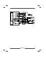
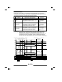
◆ Control Processing Timing
➀ AIDC Sensor variation adjustment
➁ AIDC Sensor contamination correction
➂ T/C control level setting (correction)
➃ Optimum Exposure Lamp
voltage setting (correction)
➄ AE Sensor gain adjustment
O: Performed
Item
Initial
Setting
➀
➁ ➂ ➃
➄
At the initial setup, or when the first F5
operation is run after the PC Drum has
been replaced.
O
O
O
O
O
The second or subsequent F5 operation
is run when "Exp. Lamp Manual Adj."
setting of the Tech. Rep. Choice has
been changed or the Exposure Lamp
cleaned.
O
O
O
O
O
Timing
Correction
When
The Power Switch is turned ON
Power is
(one-shot correction).
Turned
ON
If LA1
If further
intensity
correction
has
is
O
O
been
*1
necessary
varied
after ➁
by ➃
Each time the copier has made 200
Regular
copies after the Power Switch has been
Correction
turned ON.
If LA1
If further
intensity
correction
O O has
is
O
*2 *3 been
necessary
varied
after ➁
by ➃
*1: This corresponds to the first regular correction session in which a
solid-black pattern is produced to read the ID. The T/C control level is
not changed, however, even if the ID is outside the good range.
*2: The T/C control level is changed only when the level is considered to
need two consecutive 0.5% increases or decreases.
*3: The processing is not performed if the ID is outside the specified range
(3.85 to 4.45V) in ➂.
7-4. Control for Correction for a Deteriorated PC Drum and a Faulty
AIDC Sensor
The PC Drum deteriorates with age, resulting in its surface potential being
reduced. To compensate for it, the following controls are provided according
to the period of time over which the PC Drum has turned. When the copier
detects a faulty AIDC Sensor [if adjustments of ➀ and ➁ are not possible], it
drops the AIDC Sensor control and, instead, provides the following controls
for stabilized image.
(1) The Exposure Lamp voltage setting is increased by 1V each time the
cumulative time over which the PC Drum has turned exceeds 12 hours
(720 minutes).
(2) The grid voltage (V G) is increased by 15V each time the cumulative
time over which the PC Drum has turned exceeds 36 hours (2,160
minutes).
M-24
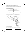
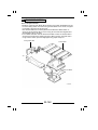
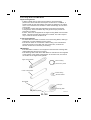
8 PC DRUM
8-1. PC Drum
• The photoconductor used in this copier is the organic photoconductor
(OPC) type.
• The drum is made up of two distinct, semiconductive materials on an
aluminum alloy base. The outer of the two layers is called the Charge
Transport Layer (CTL), while the inner layer is called the Charge
Generating Layer (CGL).
• The PC Drum measures φ100 mm × 350 mm.
Handling Precautions
This photoconductor exhibits greatest light fatigue after being exposed to
light over an extended period of time. It must therefore be protected from
light by a clean, soft cloth whenever the PC Unit has been removed from the
copier. Further, use utmost care when handling the PC Drum to prevent it
from being contaminated.
PC Drum
PC Drum
Cross-Sectional View
CTL
CGL
Aluminum
Cylinder
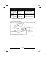
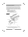
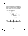
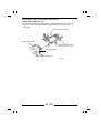
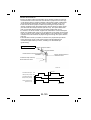
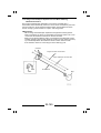
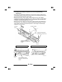
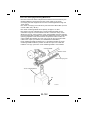
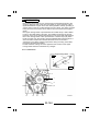
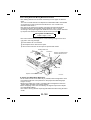
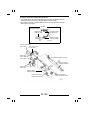
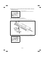
8-2. PC Drum Drive Mechanism/Control
<PC Drum Drive Mechanism>
• Drive for the PC Drum comes from PC Drum Drive Motor M5.
• When the PC Unit is slid into the copier, Catch A engages with Catch B on
the rear flange of the PC Drum. This transmits the drive from M5 to the PC
Drum.
M5
A
PC Drum
B
1075M045AA
M-25
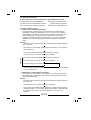
<PC Drum Drive Control>
M5 is energized and deenergized by the output from pin 52 of IC5A on
Master Board PWB-A.
= M5 Energization Timing =
M5 is energized at different timings depending on which drawer the paper is
fed from. Timer value T1, which is the period between the press of the Start
Key and the energization of M5, varies with the paper source as listed
below. This ensures that the PC Drum turns for a given period of time for
each copy cycle regardless of the paper source.
Paper Source
T1
1st and 2nd Drawer
5msec
3rd Drawer
290msec
Multi Bypass Table
600msec
= M5 Deenergization Timing =
M5 is deenergized approx. 1,250 msec. after Scanner Control Processor
Board PWB-J has output a SCEND signal.
1075C01MAA
M-26
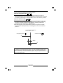
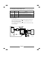
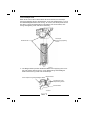
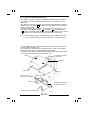
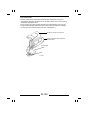
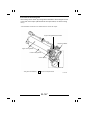
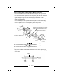
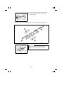
8-3. Grounding of the PC Drum
The PC Drum ground point is inside the rear end. When the PC Unit is slid
into the copier, the Drum Holding Shaft contacts the ground point. This
provides for assured grounding of the PC Drum through the Ground Plate in
the rear to the frame of the copier.
Conductive
Grease
Drum Holding
Shaft
Ground Point
Ground
Plate
Drive Gear
Coupling Gear
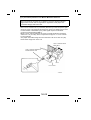
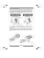
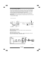
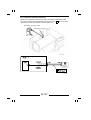
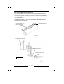
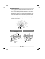
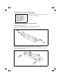
8-4. Drum Dry Heater
• Drum Dry Heater H4 is located beside the Image Transfer/Paper Separator
Coronas. It is a panel heater that prevents condensation from forming on
the surface of the PC Drum.
• H4 turns ON when:
1. The power cord is plugged in the wall outlet.
2. Power Switch S1 is in the OFF position.
3. Drum Dehumidifying Switch S9 is in the ON position.
H4
M2
S9
Image Transfer/Paper
Separator Coronas
1075C02MAA
M-27
9 DRUM CHARGING
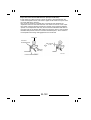
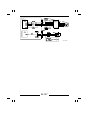
9-1. PC Drum Charge Corona
• The PC Drum Charge Corona of this copier is provided with two corona
wires and Scorotron grids, depositing a DC negative charge evenly across
the entire surface of the PC Drum.
• When PC Drum Charge HV HV1 turns ON, a voltage of approx. DC-6kV
flows through the two wires and a corona emission begins. A grid voltage
(VG) is applied to the two grid meshes, thereby ensuring that the charge
level is maintained evenly across the entire surface of the PC Drum.
• The grid voltage (V G) applied to the grid meshes is varied to compensate
for any drop in the surface potential (V0) which could occur with age. (For
more details, see page M-24.)
• VG is controlled by the Constant-Voltage Circuit in HV1 to remain in the
range between DC−650V and −890V according to the Grid Control pulse
output from Master Board PWB-A. It is initially set at DC−770V.
• The corona unit is provided with a mechanism that cleans its two wires at a
given timing. It effectively removes from the wires any toner and dust
particles which would otherwise cause uneven charging. (For more details,
see p. M-31.)
Corona Wires
Grid Mesh
Grid Mesh
PC Drum
1075M047AA
VG
DC (−) 6kV
HV1
GND
Corona Wires
Grid Meshes
PC Drum
1075M048AA
M-28
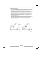
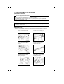
<Theory of Scorotron System with Two Wires>
HV1 turns ON and DC negative corona
emissions begin from the two corona
wires. A grid voltage according to the
Grid Control pulse is applied to the two
grid meshes.
HV1
Constant-Voltage
Circuit
PC Drum
Since there is a potential difference
between the grid mesh and PC Drum at
this time, the negative charge of the
corona emission flows through the grid
mesh to the surface of the PC Drum,
resulting in the surface being charged to
a relatively even level by the 1st
Scorotron Unit.
During this time, the PC Drum is being
charged and its surface potential
remains low.
Like the 1st Scorotron Unit, the 2nd Unit
deposits negative charge on the surface
of the PC Drum. The potential of the PC
Drum then becomes equal to that of the
grid mesh (i.e., it reaches the grid
voltage as set by the Grid Control pulse).
HV1
Constant-Voltage
Circuit
PC Drum
When the PC Drum potential equals the
grid mesh potential, the DC negative
corona current flows through the grid
mesh though HV1 to the ground. The
surface of the PC Drum will therefore
never be charged above the given level.
M-29
9-2. Control of the PC Drum Charge Corona
The PC Drum Charge Corona is turned ON and OFF by the output signal
from pin 76 of IC5A on Master Board PWB-A.
<ON Timing>
The PC Drum Charge Corona/Grid voltage output from PC Drum Charge HV
HV1 is turned ON approx. 400 msec. after PC Drum Drive Motor M5 has
been energized (see p. M-26).
<OFF Timing>
The PC Drum Charge Corona/Grid voltage output from HV1 is turned OFF
approx. 280 msec. after Scanner Control Processor Board PWB-J has
output a SCEND signal.
1075C03MAA
M-30
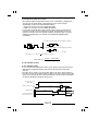
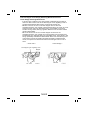
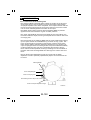
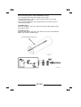
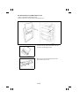
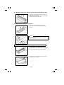
9-3. PC Drum Charge Corona Wires Cleaning Mechanism/Control
The PC Drum Charge Corona is provided with a mechanism that
automatically cleans its two corona wires. It effectively removes from the
wires any toner and dust particles which would otherwise cause uneven
charging, white streaks on copies, and charge leak.
<Mechanism>
• When PC Drum Charge Wire Cleaning Motor M21 is energized, its drive
is transmitted to the Screw Shaft. This in turn moves the Cleaner
mounted on the Screw Shaft.
• M21 is a two-phase stepping motor. The Cleaner is detected at its
standby position (which is the reference position for its cleaning motion)
by Drum Wire Cleaner Home Position Sensor PC54.
• The Cleaner makes one round trip per each cleaning cycle.
PC54
Cleaner
Corona Wires
Actuator
M21
Screw Shaft
M-31
<Control>
• The PC Drum Charge corona wires are automatically cleaned under the
following conditions. The cleaning function is, however, disabled if the
"Charge Wire Cleaning" function of "System Input" available from the Tech.
Rep. mode has been set to "Off".
(1) A period of 200 msec. has elapsed after Power Switch S1 has been
turned ON.
(2) The number of copies made exceeds 2,000 after S1 has been turned ON
and 10 minutes elapse after the last copy cycle has been completed (the
same timing as the auto clear when paper is empty).
(3) A PC Drum Charge Corona malfunction (C0200), which has been
detected, is reset.
(4) A misfeed/malfunction, which has been detected, is reset with a sheet of
paper remaining at the area near the Image Transfer/Paper Separator
Corona.
• No control panel indication is given for the cleaning cycle and the copier
accepts the press of the Start Key, though it only feeds the paper up to the
Synchronizing Rollers and starts the scan after the cleaning cycle is
completed.
• If the timing arrives for the timer power OFF function during a cleaning
cycle, the copier is turned OFF after the current cleaning cycle is
completed.
• M21 is energized and deenergized by a signal output from pin 63 of IC4A
on PWB-A and fed via PC Drum Charge Wire Cleaning Motor Drive Board
PWB-P1.
• The Cleaner is detected at its standby position when the light blocking plate
of the Cleaner blocks Drum Wire Cleaner Home Position Sensor PC54.
• When the above conditions for auto wire cleaning are met, the cleaning
sequence is carried out at the following timing.
200msec
Cleaning Conditions Met
12sec
115msec
IC4A-63
M21
Turning Forward
OFF
OFF
Turning Backward
PC54
Unblocked
Blocked
1075T95MCA
1075C04MAA
M-32
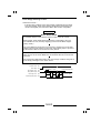
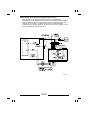
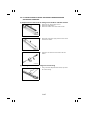
9-4. Ozone Filter
• Ozone produced by the PC Drum Charge Corona is absorbed by the
Ozone Filter as the air is drawn out of the copier by Ventilation Fan Motor
M19.
• This Ozone Filter is also used to absorb ozone produced by the Image
Transfer/Paper Separator Coronas from the air drawn out of the copier by
M19.
• M19 is energized and deenergized by the output from pin 49 of IC5A on
PWB-A.
PC Drum Charge Corona Duct
Image Transfer/Paper
Separator Coronas
PC Drum Charge Corona
Ozone Filter
Rear of Copier
M19
<M19 Energization Timing>
M19 is energized at the same time when PC Drum Drive Motor M5 is
energized (see p. M-26).
<M19 Deenergization Timing>
M19 is deenergized approx. 4,600 msec. after the trailing edge of the last
copy has moved past Paper Exit Sensor PC36.
1075C05MAA
M-33
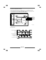
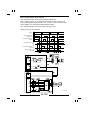
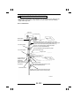
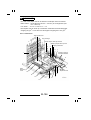
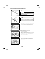
10 OPTICAL SECTION
• As the Scanner is moved by Scanner Motor M11, the light from Exposure
Lamp LA1 is reflected off the original and guided through the six mirrors
onto the surface of the PC Drum to form the electrostatic latent image.
10-1. Construction
5
3
1
10
6
4
11
8
2
7
9
12
13
14
21
22
15
16
17
18
20
19
M-34
Part Name
Symbol
PC1
Function
1
Scanner Reference
Position Sensor
Provides the reference position for Scanner
movement.
2
Scanner Drive Cable
(Rear)
3
Scanner Control
Processor Board
PWB-J
Mainly controls M11.
4
Exposure Lamp
Regulator
PU5
Applies an appropriate voltage to Exposure
Lamp LA1.
5
Scanner Motor
M11
Drives the Scanner and 2nd/3rd Mirrors
Carriage by way of the Scanner Drive Cables.
6
Lens X Direction
Reference Position
Sensor
PC2
Provides the reference position for the Lens to
move in the X-direction (feeding direction).
7
Lens Y Direction
Reference Position
Sensor
PC3
Provides the reference position for the Lens to
move in the Y-direction (crosswise direction).
8
Lens Y Direction
Drive Motor
M13
Moves the Lens in the Y-direction (crosswise
direction).
9
Lens
Driven by Scanner Motor M11 to move the
Scanner and 2nd/3rd Mirrors Carriage. (The
front Scanner Drive Cable performs the same
function.)
Brings together rays of light reflected off the
original.
10 4th/5th Mirrors
Carriage
Corrects the conjugation distance according to
the current zoom ratio.
11 4th Mirror
Reflects the light from the 3rd Mirror and Lens
onto the 5th Mirror.
12 5th Mirror
Reflects the light from the 4th Mirror onto the
6th Mirror.
13 6th Mirror
Reflects the light from the 5th Mirror onto the
surface of the PC Drum.
14 Lens X Direction
Drive Motor
M12
15 Lens Drive Cable
16 AE Sensor Board
Moves the Lens in the X-direction (feeding
direction) by way of the Lens Drive Cable.
Transmits drive from M13 to move the Lens in
the X-direction (feeding direction).
PWB-H
Measures the intensity of the light reflected off
the original.
17 Scanner
Scans the original.
18 1st Mirror
Reflects the light from the original onto the 2nd
Mirror.
19 2nd/3rd Mirrors
Carriage
Maintains the optical path length between the
original and PC Drum.
20 Optical Section
Cooling Fan Motor
M17
Cools the optical section.
21 2nd Mirror
Reflects the light from the 2nd Mirror onto the
Lens.
22 3rd Mirror
Reflects the light from the 1st Mirror onto the
3rd Mirror.
M-35
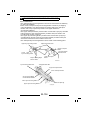
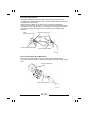
10-2. Function of Exposure Components
Book
2
Original Glass
1
3
6
5
4
1st Mirror
1. Auxiliary Reflector
:
Reflects light onto the areas that Exposure Lamp LA1
cannot illuminate when an original does not lie flat on
the Original Glass (such as a book). It functions to
reduce shadows which would otherwise be transferred
to the copy.
2. Aperture Plates:
:
Regulate the amount of LA1 light illuminating the
original surface. (There are four plates.)
3. Exposure Lamp
Thermal Fuse TF1
:
Becomes electrically open (blows) if the temperature in
the area surrounding the Main Reflector runs
excessively high, thereby preventing LA1 from being
kept ON or turning ON with the maximum line voltage.
4. Main Reflector
:
Ensures that light from LA1 exposes all areas of the
original.
5. Exposure Lamp LA1
:
A halogen frost lamp is used and its light distribution
characteristics keep the intensity of the light remaining
flat.
6. Intensity Correction
Mirror
:
Fitted on the front and rear ends of the Scanner, these
mirrors correct the intensity of the light emitted by LA1
slightly attenuated at the very ends.
M-36
10-3. Exposure Lamp LA1 Control
• The voltage applied to Exposure Lamp LA1 is controlled by changing the
duty ratio of the pulse width of the Exposure Lamp Control signal
(AVRPWM*) output from Master Board PWB-A.
* AVR is an acronym for Auto Voltage Regulator.
PWM is an acronym for Pulse Width Modulation.
• For possible contamination of the optical system and to incorporate any
correction made in the grid voltage, the copier automatically varies the
optimum intensity of the LA1 light and adjusts AE Sensor gain to ensure
stabilized image quality. (For details, see "IMAGE STABILIZATION
SYSTEM.")
<To lower the image density, the Lamp voltage is reduced.>
t
H
t'
L
(t > t')
<To raise the image density, the Lamp voltage is increased.>
T
(t > t')
t'
Duty Ratio (%) =
Period T
1075T96MCA
Pulse Width t / Period T
Duty Ratio (%) =
Period T - Pulse Width t
Period T
(1) LA1 ON/OFF Control
◆ LA1 ON/OFF Timing
• LA1 turns ON and the Scanner starts a scan motion when PC Drum Drive
Motor M5 is energized following the press of the Start Key and paper
take-up.
• During a return motion, LA1 turns OFF approx. 50 msec. after the start of
the return motion and remains OFF for approx. 20 msec. before turning ON
again. (It turns OFF 50 msec. after the Scanner has returned to the position
of Scanner Reference Position Sensor PC1.)
PC Drum Drive ON
Motor (M5) OFF
Exposure Lamp (LA1)
Energized
20 msec
ON
50 msec
ON
OFF
50 msec
SCEND Signal
H
L
Scan
Return
Start of Return
Scanner Reference
Position Sensor (PC1)
H
L
Unblocked H
Scanner stops
at PC1.
Blocked L
1075T97MCA
M-37
(2) Auto Exposure Control
<Overview>
• The copier is provided with the Auto Exposure mode in which the
voltage applied to LA1 is automatically increased or decreased as
necessary so that copies of consistent quality are produced regardless
of whether, for example, the original has a dark background or is a
pencil line drawing.
• AE Sensor Board PWB-H beside the Lens measures the intensity of the
light reflected off the 3rd Mirror, which results in the black/white ratio of
an area of 210 mm (W) × 8 mm (L) of the original being measured. As
the original is being scanned in the Auto Exposure mode, PWB-H
senses the image density of the original (or the intensity of the light
reflected) on a real-time basis.
• In this mode, the copier either increases or decreases the LA1 voltage
according to the difference between the AE Sensor output and reference
voltage during the period between when the Image Leading Edge signal
(BASE) is output and when LA1 is turned OFF.
Surface of Original
3rd Mirror
Original
210 mm
Exploded
View
Scan
Direction
8 mm
210 mm
A Given
Distance
Slit
3rd Mirror
AE Sensor Board
PWB-H
AE Sensor Board
PWB-H
M-38
This area corresponds
to a 210-mm-wide band
across the original.
<Operation/Control>
With the copier set into the Auto Exposure mode (the Touch Panel showing
"Auto Expo."), press the Start Key. Then, LA1 is turned ON at the central
manual exposure level (EXP5) and the Scanner leaves its home position
(PC1 blocked) to travel up to the leading edge position of the original
[where the Image Leading Edge signal (BASE) goes from HIGH to LOW].
This starts the automatic exposure control.
Control by AE Sensor Board PWB-H
Light reflected off the original strikes PD1H (photodiode) and PWB-H
converts its intensity to a corresponding voltage value, outputting an AE
Sensor analog voltage to Master Board PWB-A. (The higher the intensity of
the light striking PD1H, the lower the AE Sensor analog voltage.)
Original
Light
Intensity
Analog Output Voltage
Light
High
Low
Dark
Low
High
Control by Master Board PWB-A
Receiving the AE Sensor analog voltage, PWB-A compares it with the
reference voltage. It increases the Lamp voltage if the input voltage is
higher than the reference, and decreases it if the input is lower than the
reference. It varies the duty ratio of the pulse width of the Exposure Lamp
Control signal (AVRPWM) and outputs the pulse signal to Exposure Lamp
Regulator PU5.
Control by Exposure Lamp Regulator PU5
PU5 controls the Exposure Lamp voltage according to the input pulse
signal.
M-39
(3) Manual Exposure Control
• When either one of the Exposure Control Keys (Lighter or Darker) on the
Touch Panel is touched, it sets the copier into the Manual Exposure mode.
In this mode, the copier permits the user to vary the Lamp voltage (i.e., the
exposure level) in nine different steps.
<Operation/Control>
Touch the Exposure Control Key as necessary.
Control by Master Board PWB-A
The exposure level data is sent from the control panel to PWB-A via MSC
Board PWB-B.
PWB-A converts the exposure level data to a pulse signal and outputs it to
PU5.
Control by Exposure Lamp Regulator PU5
According to the input pulse signal, PU5 sets the Lamp voltage (variable in
nine steps).
M-40
1075C26MAA
M-41
10-4. Intensity Correction
(1) Because of the nature of the Lens, the intensity of the LA1 light after
passing through the Lens tends to be higher at the center and lower
toward both ends. To solve this problem, there is a Lens Aperture Cover
installed at the back of the Lens. It limits the amount of light at the center
to ensure that an even amount of light strikes the surface of the PC Drum.
(2) When a zoom ratio is large, it results in the intensity of light striking the
surface of the PC Drum decreasing. The following exposure corrections
are made according to the zoom ratio to correct this problem. (Particular
correction ratios are set for different zoom ratios and used to increase
the Lamp voltage. The same correction ratios are used for both the Auto
and Manual Exposure modes.)
Zoom Range
Manual/Auto
Exposure Correction
Ratio
Zoom Range
Manual/Auto
Exposure Correction
Ratio
0.500 to 0.523
+6%
1.216 to 1.401
+1%
0.524 to 0.556
+5%
1.402 to 1.546
+2%
0.557 to 0.596
+4%
1.547 to 1.675
+3%
0.597 to 0.646
+3%
1.676 to 1.796
+4%
0.647 to 0.713
+2%
1.797 to 1.911
+5%
0.714 to 0.822
+1%
1.912 to 2.000
+6%
0.823 to 1.215
±0%
M-42
10-5. Scanner and Mirrors Carriages Moving Mechanism
<Scanner>
• The Scanner projects an even amount of light from Exposure Lamp LA1,
as it moves, onto the entire surface of the original and reflects this light,
with the 1st Mirror, onto the 2nd and 3rd Mirrors.
• It is driven by Scanner Motor M11 with the Scanner Drive Cables
attached to the front and rear at a speed appropriate to the set zoom
ratio. The speed is varied from the reference speed of 340.0 mm/sec.
which is the scan speed for the full size mode.
• The Scanner is at its home position when Scanner Reference Position
Sensor PC1 is blocked. The position serves as the reference for the
scan motion.
<2nd/3rd Mirrors Carriage>
• The 2nd and 3rd Mirrors are mounted to their holder at right angles to
each other. They function to let the light reflected off the 1st Mirror strike
the 4th and 5th Mirrors through the Lens.
• The 2nd/3rd Mirrors Carriage is also moved by the Scanner Drive
Cables and pulleys driven by M11. It travels at a speed half that of the
Scanner, thereby keeping constant the optical path length between the
Original Glass and PC Drum.
• The 2nd/3rd Mirrors Carriage has been adjusted to run parallel with the
Scanner though Focus-Positioning of the Scanner and Mirrors Carriage.
Scanner Drive Cable (Rear)
Rear of Copier
PC1 Light
Blocking Plate
Scanner
Scanner
Reference
Position Sensor
PC1
Scanner Drive
Cable (Front)
Exposure Lamp LA1
1st Mirror
2nd Mirror
3rd Mirror
Front of Copier
2nd/3rd Mirrors
Carriage
M-43
<4th/5th Mirrors Carriage>
• The 4th and 5th Mirrors are mounted to their holder at right angles to
each other. They function to let the light reflected from the 3rd Mirror
and through Lens strike the 6th Mirror via themselves.
• The 4th/5th Mirrors Carriage is moved in the X-direction (feeding
direction) to correct the conjugation distance (the distance between the
original and the surface of the PC Drum) according to the set zoom ratio.
Its drive comes from Lens X Direction Drive Motor M12 which turns a
cam. The rotary motion of the cam is changed to a reciprocating, or
straight-line, motion of the carriage through a link mechanism.
• To ensure that a focused image of the original is reproduced on the
surface of the PC Drum when in an enlargement or reduction mode, the
conjugation distance must be greater than that when in the full size
mode. To accomplish this, the 4th/5th Mirrors Carriage is moved in the
direction of a greater conjugation distance.
• There are three different types of cams available according to the focal
length of the Lens. When the Lens is replaced, the cam must also be
replaced with one appropriate for the focal length of the new Lens.
Lens Focal Length
(in mm)
Cam ID Marking
Cam Part No.
213.50 to 214.35
−
1046-4823-02
214.40 to 215.20
0
1046-4821-02
215.25 to 216.10
+
1046-4822-02
Note: In the illustration below, if the 4th/5th Mirrors Carriage is located at the
full size position, it moves in the direction of the arrow ➡ for all
enlargement or reduction modes.
4th Mirror
5th Mirror
4th/5th Mirrors Carriage
6th Mirror
n
ctio
u
ed
Enlargement Side
e
t/R
Siz men
l
l
Fu arge
l
En
Link Mechanism
Lens X Direction Drive
Motor M12
Cam
M-44
10-6. Scanner Motor M11 Control
<Overview>
• A DC servomotor is used for Scanner Motor M11. The pulse width
modulation, or PWM, control is employed in which the average voltage is
controlled by varying the width of the Scanner drive pulse which is the
voltage input to M11.
• M11 has a built-in photosensor and pulse disk. Their function is to
convert the Motor shaft speed into a corresponding series of pulses.
This pulse signal is input to Scanner Control Processor Board PWB-J.
• PWB-J then calculates the Motor speed using the period of the pulse
signal applied to it and controls the Scanner drive pulse which is to be
applied to the Motor. This effectively stabilizes the Motor speed.
• The pulse signal applied to PWB-J is also used to determine the
distance over which the Scanner should travel. This distance is
represented by the number of pulses corresponding to each paper size
and zoom ratio.
<Scan/Return Switching and Braking of M11>
• M11 is turned forward to move the Scanner in the scan direction, turned
backward to move the Scanner in the return direction, or braked by the
Motor Forward and Backward signals input to PWB-J. Details are as
follows.
Motor Forward Signal
(Pin 13 of IC3J)
Motor Backward Signal
(Pin 15 of IC3J)
Turns Forward
H
L
Turns Backward
L
H
Braked (in Scan Motion)
L
H
Braked (in Return Motion)
H
L
• The brake control in the return motion is provided as follows, since M11
builds up its speed to the maximum level during the return motion. The
Motor Backward signal is first alternated between HIGH and LOW states
to reduce the input voltage to M11 to a low level. After M11 is
decelerated to a given speed through this operation, the above brake
control is performed.
Braking
Motor Forward Signal
H
L
Motor Backward Signal
H
L
Scanner Motor M11
Deceleration Braking
Forward Rotation (Scan)
Backward Rotation (Return)
1075T98MCA
M-45
<Scanner Speed Control>
• The speed of M11 is controlled by varying the width of the Scanner drive
pulse output from Scanner Control Processor Board PWB-J. (This
means that the current flowing through M11 is varied.)
Scanner Drive Pulse Output Waveform
Period T
High-Speed Rotation
Pulse Width t
1075T103CA
Period T
Low-Speed Rotation
Pulse Width t'
1075T104CA
1075C25MAA
M-46
10-7. Lens Drive Mechanism/Control
(1) Lens Drive Mechanism
• In this copier, registration for the original is to one side, while the copy
paper is fed through the center of the copier. For this reason, the Lens
must be moved according to the paper size even in the full size mode
(×1.000). The Lens is moved independently in the X-direction (feeding
direction) and Y-direction (crosswise direction).
(2) X (Feeding) Direction Lens Motion Mechanism/Control
The Lens is moved in the X-direction to obtain a conjugation distance
appropriate for the set zoom ratio.
• The Lens is moved in the X-direction by the cable wound around the pulley
turned by Lens X Direction Drive Motor M12. (M12 is a stepping motor and
turned forward or backward by the pulse signal output from Scanner
Control Processor Board PWB-J.)
• When a zoom ratio is selected, the Lens is moved as follows. The M12’s
shaft turns 7.5° per step, which is equivalent to approx. 0.19 mm of linear
Lens movement.
• The Lens is at the full size position when the Lens X-Unit moves a distance
of approx. 95 mm from the position at which it has unblocked Lens X
Direction Reference Position Sensor PC2 (the sensor going from LOW to
HIGH). This position provides the reference for Lens movement in various
zoom ratios.
• As the Lens moves in the X-direction, the 4th/5th Mirrors Carriage moves
to correct the conjugation distance appropriate for the zoom ratio.
L Blocked
PC2
Lens X Direction
Reference Position
Sensor PC2
4th/5th Mirrors
Carriage
Lens X-Unit
95 mm
Enlargement
Side
Full Size
Position
ion
uct
d
/Re
Lens Drive
Cable
Lens X Direction
Drive Motor M12
ize ent
ll S
Fu argem
l
En
1075M006AA
M-47
◆ Lens X Direction Reference Position Return
From the enlargement side ( H ➡ L )
➀ M12 is energized to move the Lens toward the reduction side and
deenergized when Lens X Direction Reference Position Sensor PC2 goes
from HIGH (unblocked) to LOW (blocked). This is the reference position.
From the reduction side ( L ➡ H )
➀ M12 is energized to move the Lens toward the enlargement side. From
➁
the point at which PC2 goes from LOW (blocked) to HIGH (unblocked),
the Lens is further moved two steps (approx. 0.38 mm) toward the
enlargement side before M12 is deenergized.
M12 is energized to turn backward and, when PC2 goes from HIGH
(unblocked) to LOW (blocked), it is deenergized. This is the reference
position.
Lens X Direction Reference
Position Sensor PC2
Enlargement Side ( H )
Reduction Side ( L )
➀
2 Steps
➀
➁
To enhance Lens positioning accuracy, the Lens is always brought to the
reference position from the enlargement side. This compensates for the
error produced by backlash in the drive gears and part-to-part variations in
the moving mechanism.
M-48
(3) Y (Crosswise) Direction Lens Motion Mechanism/Control
The Lens must be moved in the Y-direction, since the original is always
aligned with the rear side for registration regardless of the paper size
(crosswise length) and zoom ratio.
• The Lens is moved in the Y (crosswise) direction by a rack and pinion gear
driven by Lens Y Direction Drive Motor M13. (M13 is a stepping motor and
turned forward or backward by the pulse signal output from Scanner
Control Processor Board PWB-J.)
• When a zoom ratio is selected, the Lens is moved as follows. The M13’s
shaft turns 1.8° per step, which is equivalent to approx. 0.11 mm of linear
Lens movement.
* The paper size widths range from the minimum 100 mm to 297 mm (A3).
* Zoom ratios range from 0.5 to 2.0.
Lens Y Direction Drive
Motor M13
Lens Y Direction Reference
Position Sensor PC3
Lens
Lens Y-Unit
M-49
◆ Lens Y Direction Reference Position Return
The movement of the Lens in the Y (crosswise) direction should be referred
to as that in the plus (+) or minus (−) direction, instead of in the enlargement
or reduction direction, since the Lens also needs to be moved in the Y
direction according to the paper size (width).
From the plus (+) side ( L ➡ H )
➀ M13 is energized to move the Lens toward the minus (−) side and
deenergized when Lens Y Direction Reference Position Sensor PC3 goes
from LOW (blocked) to HIGH (unblocked). This is the reference position.
From the minus (−) side ( H ➡ L )
➀ M13 is energized to move the Lens toward the plus (+) side. From the
➁
point at which PC3 goes from HIGH (unblocked) to LOW (blocked), the
Lens is further moved two steps (approx. 0.22 mm) toward the (+) side
before M13 is deenergized.
M13 is energized to turn backward and, when PC3 goes from LOW
(blocked) to HIGH (unblocked), it is deenergized. This is the reference
position.
Rear Side, Enlargement Direction
➀
+ Side ( L )
Lens Y Direction Reference
Position Sensor PC3
➁
2 Steps
− Side ( H )
➀
Front Side, Reduction Direction
To enhance Lens positioning accuracy, the Lens is always brought to the
reference position from the plus (+) side. This compensates for the error
produced by backlash in the drive gears and part-to-part variations in the
moving mechanism.
M-50
1075C60MAA
M-51
(4) Lens Movements in the X/Y-Direction
◆ When Power Switch is turned ON
(1) The Scanner is returned to the home position, if it is not there. It is at the
home position when Scanner Reference Position Sensor PC1 is blocked.
(2) The Lens is returned to the reference position in the Y-direction.
Lens Y Direction Reference Position Sensor PC3 ... L ➡ H
(3) The Lens is returned to the reference position in the X-direction.
Lens X Direction Reference Position Sensor PC2 ... H ➡ L
(4) The Scanner makes a prescan motion.
(5) Lens drive check in the X-direction.
(6) Lens drive check in the Y-direction.
(7) The Lens moves to the full size position.
Note: Steps (5) and (6) are not performed when the Lower Front Door is
opened and closed (with DC5V being supplied).
M-52
10-8. Optical Section Cooling Fan Motor
• Optical Section Cooling Fan Motor M17 draws air from the outside into the
inside of the copier to cool the areas around the optical section (especially
the Original Glass) which is heated by a lit Exposure Lamp LA1.
Fusing Motor (M6)
ON
OFF
600 msec
PC Drum Drive ON
Motor (M5) OFF
Optical Section Cooling ON
Fan Motor (M17) OFF
Paper Exit Sensor
(PC36)
4 sec
H
L
Paper Fed Out
1075T99MCB
1075C29MAA
M-53
11 ORIGINAL SIZE DETECTING SYSTEM
• The conventional original size detecting system, which uses the intensity of
the light reflected off the original as the basis for detection, is not 100%
capable of detecting originals with high image density. The new system, on
the other hand, determines the distance between the sensor and the
original and is less affected by the color, reflectivity, paper quality, and
other factors of the original.
• The adoption of this new system has resulted in the following
improvements.
➀ Higher maximum original image density level that can be detected, up
➁
➂
from a conventional 0.25 to 0.8 according to the manufacturer’s
comparison.
The system is less susceptible to the image density and color of the
original.
The optional sensors enable the detection of originals both of the metric
as well as inch systems.
11-1. Construction
4
Original Cover
Detecting Lever
5
1
3
8
2
6
7
Control Panel
M-54
Name
Symbol
1 Size Reset Switch
S7
Function
Clears the preceding original size data.
2
Original Size Detecting
Sensor CD2 (option)
UN7
Detects the size of the original in the
crosswise direction (i.e., width). Enables the
detection of an inch size original.
3
Original Size Detecting
Sensor CD1
UN6
Detects the size of the original in the
crosswise direction (i.e., width).
4
Original Size Detecting
Board
UN2
Determines the size of the original based on
the data provided by the Original Size
Detecting Sensors.
5
Original Cover Detecting
Sensor
PC4
Detects the position of the Original Cover,
whether it is raised or lowered.
6
Original Size Detecting
Sensor FD3 (option)
UN3
Detects the size of the original in the feeding
direction (i.e., length). Enables the detection
of an inch size original.
7
Original Size Detecting
Sensor FD2
UN4
Detects the size of the original in the feeding
direction (i.e., length).
8
Original Size Detecting
Sensor FD1
UN5
Detects the size of the original in the feeding
direction (i.e., length).
11-2. Construction of the Original Size Detecting Sensor
• The original size detecting sensors used in the system determine the
distance between the sensor and the original, which enables the detection
of originals with high image density (original density up to 0.8).
• Each sensor has two LEDs (LED1 and LED2) and one photo receiver
(PSD).
• Two types of sensor are used: the CD (crosswise) and FD (feeding
direction) sensors. Since the CD sensors are installed at a height different
from FD sensors, each type has a different setting distance as detailed
below.
CD sensors : Setting distance 124 mm
FD sensors : Setting distance 60 mm
FD Sensor
CD Sensor
LED1
PSD
LED1
LED2
LED2
M-55
PSD
11-3. Original Detection Method
• When the photo receiver receives the reflected light of the two LEDs at an
intensity that exceeds a predetermined level, the detection system
determines that an original is placed within the setting distance of the
sensor.
Original
Original Glass
Light Being
Received
Setting
Distance
Light Being
Emitted
Light Being
Received
Light Being
Emitted
1075M017AA
<When There is an Original>
<When There is No Original>
• Raise the AFR-9, place the original on the Original Glass, and lower the
AFR-9. The size of the original is determined when, at this time, the output
from Original Cover Detecting Sensor PC4 goes from HIGH to LOW (i.e.,
when the AFR-9 is lowered to an angle of 15°).
• If the AFR-9 is kept raised (PC4 remains HIGH) with an original placed on
the Original Glass, the size of the original is determined when the Start Key
is pressed.
• The original size is read by the AFR-9 if it is used for making copies.
• The previous original size data is cleared when Size Reset Switch S7 is
deactuated, which occurs when the AFR-9 is raised.
Original Cover
Detecting Lever
Actuating
Magnet
Original Size is
Detected at an
Angle of 15°.
PC4
Size Reset
Switch S7
M-56
Each sensor has a built-in signal processing circuit that outputs 8-bit serial
data to Original Size Detecting Board UN2.
Original Size
Detecting
Sensor
UN2
Reg
4
2
Vcc(su)
E P-ROM
PSD
Signal
Processing
Circuit
LED1
3
Sensor Control
Microprocessor
1
5
LED
Drive
Circuit
2 GND
LED2
Original
Size
sig
Master
CPU
PWB-A
1075M159CB
Original
M-57
11-4. Sensor Locations
• The number and location of the Original Size Detecting Sensors varies
depending on the marketing area, as given below.
●: Optional
O: Standard
CD1
(UN6)
O
O
O
Sensors
Areas
Metric Areas
Inch Areas
(Hong Kong Area)
CD2
(UN7)
●
●
O
FD1
(UN5)
O
●
O
FD2
(UN4)
O
O
O
FD3
(UN3)
●
●
O
NOTE: If the optional sensors are installed, set Jumper Connector J2 on UN2 as
illustrated below, connect CN3 and CN4 on UN2, and run the F7 operation.
For the installation of the optional Original Size Detecting Sensors, see
DIS/REASSEMBLY, ADJUSTMENT.
FD 1
Length (Inch)
FD 2
Letter C Letter L
FD3
Legal
11" × 17"
Width (Inch)
Width
(Metric)
A5L
B5L
Legal,
Letter L
A4L
B4L & B5C
Letter C,
11" × 17"
A3L & A4C
CD1
CD2
Length (Metric)
L: Lengthwise;
B5C A4C B5L A4L
B4L A3L C: Crosswise
A5L
Original Size Detecting Board UN2
PSD
CN4
CN1
CN3
J1
LED1 LED2
J2
CN2
FD1 is mounted
FD1 is not
mounted
CD2 and FD3
are mounted
CD2 and FD3
are not mounted
Position of
J1
Position of
J2
M-58
1075M018AD
11-5. Original Size Detection
• Original Size Detecting Board UN2 reads the output data provided by the
original size detecting sensors. By comparing the data from each sensor
with the threshold level, it determines whether there is an original placed
on the Original Glass. UN2 then determines the size of the original
according to the combination of the comparison results.
• The threshold level is set so that UN2 can determine whether there is an
original or not by compensating for part-to-part variations and variations in
the installed positions of the sensors. This procedure is performed by the
F7 operation.
Original Size
A3L
B4L
A4L
A5L
Invoice:
5-1/2" × 8-1/2"
A4C
Letter L: 8-1/2" × 11"
11" × 17"
Legal: 8-1/2" × 14"
FLS: 8-1/2" × 13"
Letter C: 11"×8-1/2"
No Original
FD1
LED2
O
O
O
FD2
LED1 LED2
O
O
O
O
O
O
FD3
LED1 LED2
O
O
O
O
●
l
CD1
LED1 LED2
O
O
●
O
●
l
CD2
LED1
O
●
●
O
●
●
●
l
l
●
●
O
O
O
O
O
O
●
●
O
O
O
O
●
●
●
●
O
O
O
●
●
●
●
O
O
O
●
●
●
●
O
O
●
l
l
O
●
O
●
l
O
l
O
●
O
●
●
O
●
O
●
●
●
●
●
●
O: Original Present
●: Original Not Present
Notes: • UN2 does not use the data provided by LED1 of Original Size
Detecting Sensor FD1 (UN5) and LED2 of CD2 (UN7) for the
determination of the original size.
• Any non-standard size is rounded off to the nearest standard size.
M-59
11-6. Original Size Detection Processing
The copier performs different processing for the detection of the original size
under different copier conditions as follows.
Copier Condition
Original Size Detection Processing
The Original Cover is left LEDs of Original Size Detecting Sensors UN3 to UN7
open.
project light onto the original and the photo receivers
of the sensors receive the reflected light and transmit
* Original Cover
the corresponding data to Original Size Detecting
Detecting Sensor PC4
Board UN2.
remains deactivated.
UN2 determines the original size based on the
combination of the output data from the original size
detecting sensors.
1
UN2 divides the original size data into two parts and
transmits 4-bit parallel data to Master Board PWB-A
approx. every 73 msec.
PWB-A combines the 4-bit original size data back into
8-bit data and stores it in memory.
2
The Original Cover is
lowered to an angle less
than 15°.
* PC4 is activated.
The Original Cover is
completely lowered.
3
* The magnets fitted to
the Original Cover
actuate Size Reset
Switch S7.
The Original Cover is
raised to an angle less
4 than 15°
The original size data is latched when PC4 is
activated and the original size is set.
The copier selects the appropriate paper size based
on the set original size data and selects the paper
source loaded with paper of that size, with the paper
size indicated on the control panel (when in the Auto
Paper or Size mode).
If the copier is unable to find the target paper size, it
gives a paper-empty warning message.
The set original size data and selected paper size are
reset.
* S7 is deactuated.
* PC4 remains activated.
The Original Cover is
The copier proceeds with the next original size
raised to an angle more
detection sequence.
5
than 15°.
* PC4 is deactivated.
Note:
If the Start Key is pressed with the Original Cover raised (PC4 is
deactivated and S7 deactuated), UN2 transmits the original size
data available when the Start Key is pressed to Master Board
PWB-A for the selection of the paper size.
M-60
11-7. Original Size Detection Circuit
1075C22MAA
M-61
12 IMAGE ERASE LAMP
12-1. Image Erase Lamp LA3
• Any areas of charge which are not to be developed along the leading,
trailing, front, and rear edges are neutralized by lighting up Image Erase
Lamp LA3. This effectively prevents non-image areas from being dirtied
and economizes on toner consumption. The lamp also functions to erase
the leading and trailing edges, and the areas defined in the File Margin and
Edge/Frame Erase mode, of the electrostatic latent image on the surface of
the PC Drum.
• LA3 consists of 64 LEDs arranged at 5-mm pitch in a row. Different LEDs
are turned ON at different timings depending on the size of the paper to be
fed, zoom ratio, and mode (Margin, Erase).
LA3
LA3
M-62
12-2. Image Erase Lamp LA3 ON/OFF Control
LA3 is controlled by the following signals output from Master Board PWB-A.
Signal Name
Signal
Output Pin
DATA
IC1A-5
64-bit serial data signal controlling turning ON and
OFF each of the 64 LEDs of LA3.
CLK
IC1A-3
Synchronizing signal to transmit data serially.
MODE
IC1A-4
Signal causing LA3 to latch the transmitted data.
STROBE
IC1A-2
Signal to turn ON LA3 according to the latched data.
Function
= Flow of Each Signal =
In synchronism with the CLK signal, the DATA signal is input to LA3.
When all serial DATA signals are input, the MODE signal is input to
LA3 and LA3 latches the data.
As the STROBE signal is input to LA3, LEDs are turned ON according
to the latched data.
1075C06MAA
M-63
12-3. Control for Each Erase Function
<LA3 ON Start Timing>
All LA3 LEDs are turned ON approx. 250 msec. after PC Drum Drive Motor
M5 has been energized (see p. M-26) and the leading edge erase and edge
erase controls are thereafter provided.
<LA3 OFF Timing>
The LA3 LEDs are turned OFF approx. 1,050 msec. after Scanner Control
Processor Board PWB-J has output an SCEND signal, which completes a
series of erase controls.
= Leading Edge Erase =
• The image along the leading edge of the electrostatic latent image on the
surface of the PC Drum is erased by turning ON all LA3 LEDs. This
prevents a black streak which would otherwise be produced by the shadow
of the Original Width Scale. It also helps the leading edge of the paper to
be easily separated from the Fusing Rollers.
• All LA3 LEDs are kept ON for a given period of time after PWB-J has
output an Image Leading Edge signal (BASE). The leading edge erase is
then switched to edge erase. The leading edge erase time varies
depending on the zoom ratio, mode (File Margin, Edge/Frame Erase), and
whether "Leading Edge Erase" of the Tech. Rep. Choice is set to "Yes" or
"No." See the Table below.
"Yes" (4 mm)
"No"
File Margin
Normal
10
15
File Margin
Normal
20
10
15
20
Erase Width (mm)
4
14
19
24
0
10
15
20
Timer (msec.)
75
105
120
135
60
90
105
120
* In an enlargement mode, the above erase widths are made greater
according to the particular zoom ratio as follows.
Zoom Ratio
1.001 to 1.500
1.501 up
Erase Width Correction (mm)
+ 1. 7
+ 3. 4
+5
+ 10
Timer Correction (msec.)
M-64
= Edge Erase =
• The 64 LEDs are turned ON and OFF as necessary to erase unnecessary
charges along both the front and rear edges of the image as well as those
deposited in a reduction mode. This economizes on toner consumption and
prevents black streaks from occurring on the copy.
• Which LEDs are turned ON for edge erase depends on the copy paper size
and zoom ratio setting. In the full size and enlargement mode, it depends
on the copy paper size, while in a reduction mode, it depends on the zoom
ratio and copy paper size.
• Since the copy paper is fed through the center of the copier in this copier,
LEDs are turned ON as detailed below for different copy paper sizes. We
call the table LED ON Pattern A which is used to control edge erase in the
full size and enlargement mode. Edge erase is also provided for multi
bypass copying in which this copier detects the paper size (in the
crosswise direction only).
LED ON Pattern A (For Metric Area)
L1: Frontmost LED; L64: Rearmost LED; O: ON; X: OFF; L appended
to paper size: Lengthwise (L25 to L40 are OFF)
Paper
Size
LEDs
L 1~L 8
L 9~L 16
L 17~L 24
L 41~L 48
L 49~L 56
L 57~L 64
A6L
OOOOOOOO OOOOOOOO OOOOOXXX XXXOOOOO OOOOOOOO OOOOOOOO
B6L
OOOOOOOO OOOOOOOO OOXXXXXX
XXXXXXOO OOOOOOOO OOOOOOOO
A5L
OOOOOOOO OOOOOOOO
XXXXXXXX
OOOOOOOO OOOOOOOO
B5L
OOOOOOOO OOOOOXXX
XXXXXXXX
XXXXXXXX
XXXOOOOO OOOOOOOO
A4L
OOOOOOOO OOXXXXXX
XXXXXXXX
XXXXXXXX
XXXXXXOO OOOOOOOO
B4L
OOOOOOXX
XXXXXXXX
XXXXXXXX
XXXXXXXX
XXXXXXXX
XXOOOOOO
A3L
OOXXXXXX
XXXXXXXX
XXXXXXXX
XXXXXXXX
XXXXXXXX
XXXXXXXO
XXXXXXXX
LED ON Pattern A (For Inch Area)
L1: Frontmost LED; L64: Rearmost LED; O: ON; X: OFF; L appended
to paper size: Lengthwise (L25 to L40 are OFF)
Paper
Size
LEDs
L 1~L 8
L 9~L 16
L 17~L 24
L 41~L 48
L 49~L 56
L 57~L 64
5-1/2"
×
OOOOOOOO OOOOOOOO
8-1/2"L
OXXXXXXX
XXXXXXXX
XXXOOOOO OOOOOOOO
8-1/2 ×
OOOOOOOO OOXXXXXX
11"L
XXXXXXXX
XXXXXXXX
XXXXXXXO OOOOOOOO
10" ×
14"L
OOOOOOXX
XXXXXXXX
XXXXXXXX
XXXXXXXX
XXXXXXXX
XXXOOOOO
11" ×
17"L
OOOOXXXX
XXXXXXXX
XXXXXXXX
XXXXXXXX
XXXXXXXX
XXXXXOOO
M-65
• In this copier, the original is aligned with a corner for registration, while the
copy paper is fed through the center of the copier. Because of that, the
reference position of the image on the surface of the PC Drum varies
according to the copy paper size. This defies a single LED ON pattern for
the reduction mode, as was used conventionally. (Different LEDs are
turned ON in the reduction mode according to the copy paper size.)
If, however, a particular LED ON pattern is established for each reduction
ratio and each paper size, it requires a much larger storage capacity and
processing time than used in the conventional copiers. An LED ON pattern
for varying reduction ratios is therefore established only with the paper size
whose crosswise length is the maximum (A3 lengthwise = 297 mm). This
pattern is called LED ON Pattern B shown on the next page. For other
paper sizes, a particular reduction ratio is converted to that in the maximum
paper size and the reduction ratio found is applied to LED ON Pattern B to
find which LEDs are ON. This saves the storage space and processing
time.
• The following formula is used to convert the actual reduction ratio to a ratio
for the maximum paper size.
MNEW = M + (PS MAX − PS) / (2 × PSMAX)
M: Actual reduction ratio
MNEW : Conversion ratio
PSMAX : Maximum paper size (A3 lengthwise = 297 mm)
PS : Paper size to be used
• Edge erase in the reduction mode is controlled by the logical sum of the
following: the LED ON data obtained by applying the ratio found through
the above formula to LED ON Pattern B and the LED ON data obtained by
applying the copy paper size to LED ON Pattern A.
Example: Copy paper size: A4 lengthwise, reduction ratio: 0.500
➀ When the variables are applied to the above formula:
MNEW = 0.500 + (297 − 210) / 2 × 297
= 0.646
➁ When 0.646 is applied to LED ON Pattern B:
We know that L42 to L64 are ON.
➂ When A4 lengthwise is applied to LED ON Pattern A:
We know that L1 to L10 and L55 to L64 are ON.
The logical sum of ➁ and ➂ are that L1 to L10 and L42 to L64 are ON.
M-66
LED ON Pattern B
O: ON; X: OFF (L1 to L32 are OFF)
Zoom Ratio
LEDs
Inch Area
Metric Area
L33 to L40
L41 to L48
L49 to L56
L57 to L64
To 0.507
To 0.511
OOOOOOOO
OOOOOOOO
OOOOOOOO
OOOOOOOO
0.508 to 0.523 0.512 to 0.527
XOOOOOOO
OOOOOOOO
OOOOOOOO
OOOOOOOO
0.524 to 0.539 0.528 to 0.543
XXOOOOOO
OOOOOOOO
OOOOOOOO
OOOOOOOO
0.540 to 0.555 0.544 to 0.559
XXXOOOOO
OOOOOOOO
OOOOOOOO
OOOOOOOO
0.556 to 0.572 0.560 to 0.576
XXXXOOOO
OOOOOOOO
OOOOOOOO
OOOOOOOO
0.573 to 0.588 0.577 to 0.592
XXXXXOOO
OOOOOOOO
OOOOOOOO
OOOOOOOO
0.589 to 0.604 0.593 to 0.608
XXXXXXOO
OOOOOOOO
OOOOOOOO
OOOOOOOO
0.605 to 0.620 0.609 to 0.624
XXXXXXXO
OOOOOOOO
OOOOOOOO
OOOOOOOO
0.621 to 0.637 0.625 to 0.641
XXXXXXXX
OOOOOOOO
OOOOOOOO
OOOOOOOO
0.638 to 0.653 0.642 to 0.656
XXXXXXXX
XOOOOOOO
OOOOOOOO
OOOOOOOO
0.654 to 0.669 0.657 to 0.673
XXXXXXXX
XXOOOOOO
OOOOOOOO
OOOOOOOO
0.670 to 0.686 0.674 to 0.689
XXXXXXXX
XXXOOOOO
OOOOOOOO
OOOOOOOO
0.687 to 0.702 0.690 to 0.706
XXXXXXXX
XXXXOOOO
OOOOOOOO
OOOOOOOO
0.703 to 0.718 0.707 to 0.722
XXXXXXXX
XXXXXOOO
OOOOOOOO
OOOOOOOO
0.719 to 0.734 0.723 to 0.738
XXXXXXXX
XXXXXXOO
OOOOOOOO
OOOOOOOO
0.735 to 0.751 0.739 to 0.754
XXXXXXXX
XXXXXXXO
OOOOOOOO
OOOOOOOO
0.752 to 0.767 0.755 to 0.771
XXXXXXXX
XXXXXXXX
OOOOOOOO
OOOOOOOO
0.768 to 0.786 0.772 to 0.787
XXXXXXXX
XXXXXXXX
XOOOOOOO
OOOOOOOO
0.787 to 0.799 0.788 to 0.803
XXXXXXXX
XXXXXXXX
XXOOOOOO
OOOOOOOO
0.800 to 0.816 0.804 to 0.820
XXXXXXXX
XXXXXXXX
XXXOOOOO
OOOOOOOO
0.817 to 0.832 0.821 to 0.836
XXXXXXXX
XXXXXXXX
XXXXOOOO
OOOOOOOO
0.833 to 0.848 0.837 to 0.852
XXXXXXXX
XXXXXXXX
XXXXXOOO
OOOOOOOO
0.849 to 0.864 0.853 to 0.868
XXXXXXXX
XXXXXXXX
XXXXXXOO
OOOOOOOO
0.865 to 0.881 0.869 to 0.885
XXXXXXXX
XXXXXXXX
XXXXXXXO
OOOOOOOO
0.882 to 0.897 0.886 to 0.901
XXXXXXXX
XXXXXXXX
XXXXXXXX
OOOOOOOO
0.898 to 0.913 0.902 to 0.917
XXXXXXXX
XXXXXXXX
XXXXXXXX
XOOOOOOO
0.914 to 0.929 0.918 to 0.933
XXXXXXXX
XXXXXXXX
XXXXXXXX
XXOOOOOO
0.930 to 0.946 0.934 to 0.950
XXXXXXXX
XXXXXXXX
XXXXXXXX
XXXOOOOO
0.947 to 0.962 0.951 to 0.966
XXXXXXXX
XXXXXXXX
XXXXXXXX
XXXXOOOO
0.963 to 0.978 0.967 to 0.982
XXXXXXXX
XXXXXXXX
XXXXXXXX
XXXXXOOO
0.979 to 0.994 0.983 to 0.998
XXXXXXXX
XXXXXXXX
XXXXXXXX
XXXXXXOO
XXXXXXXX
XXXXXXXX
XXXXXXXX
XXXXXXXO
0.995 to
0.999 to
M-67
= Trailing Edge Erase =
• The image along the trailing edge of the electrostatic latent image on the
surface of the PC Drum is erased by turning ON all LA3 LEDs. This
prevents the Fusing Rollers from being dirtied by excess toner and offset
from occurring as the trailing edge of the paper is fused.
• The timing at which the trailing edge erase is switched from edge erase
varies depending on the mode (File Margin, Edge/Frame Erase) and
whether "Trailing Edge Erase" of the Tech. Rep. Choice is set to "Yes" or
"No," with reference to the SCEND signal output from PWB-J. See the
Table below.
"Yes" (4 mm)
File Margin
Normal
10
Erase Width (mm)
Timer (msec.)
"No"
15
File Margin
Normal
20
10
15
20
4
14
19
24
0
10
15
20
255
225
210
195
270
240
225
210
M-68
13 DEVELOPING UNIT
13-1. Construction
• This copier employs the New Micro-Toning developing system equipped
with three Sleeve/Magnet Rollers.
• The toner fed up to the Toner Replenishing Sleeve/Magnet Roller is
supplied to the turning 1st and 2nd Sleeve/Magnet Rollers. From there, it is
supplied to the electrostatic latent image on the surface of the PC Drum to
form a visible, developed toner image of the original.
• Toner is supplied from the Toner Bottle by way of the Main Hopper and
Sub Hopper.
2
3
1
4
20 21
19
5
18
17
6
16
15
8
14
7
9
13
10
12
1
2
3
4
5
11
Toner Bottle
Toner Bottle Holder
Toner Bottle Home Position Sensor
PC30
Main Hopper Toner Replenishing
Motor M14
Sub Hopper Toner Conveying Screw
12 Bucket Roller
13 Developer Regulator
14 2nd Sleeve/Magnet Roller
15 1st Sleeve/Magnet Roller
16 Developer Scattering Prevention
Mylar
6 Sub Hopper Toner Agitating Lever
17 Developer Scattering Prevention Plate
7 Sub Hopper Toner Empty Switch S8
18 Toner Replenishing Sleeve/Magnet
Roller
8 Toner Regulator
19 Doctor Blade
9 Developer Conveying/Agitating Screw 20 Magnet Sheet
10 ATDC Sensor
21 Sub Hopper Toner Replenishing
Roller
11 Developing Unit Dehumidifying
Heater H6
M-69
13-2. Developing Unit Drive Mechanism
• Drive for the Developing Unit comes from PC Drum Drive Motor M5.
• Coupling Gear 2 is spring-loaded. If the protruding part of Coupling Gear 1
makes contact with that of Coupling Gear 2 when the PC Unit is slid into
the copier, spring-loaded Coupling Gear 2 is pushed back toward the rear
of the copier allowing the PC Unit to be slid into position. When drive is
later transmitted to the Developing Unit, Coupling Gear 2 is pushed to the
front by the tension of the spring to mesh positively with Coupling Gear 1.
• The following parts are driven by M5. Given in ( ) are the drive gears keyed
to the illustration.
Sub Hopper Toner Conveying Screw ➀ (A)
Sub Hopper Toner Agitating Lever ➁ (B)
Developer Conveying/Agitating Screw ➂ (C)
Bucket Roller ➃ (Coupling Gear 1)
Toner Replenishing Sleeve/Magnet Roller ➄ (D)
1st and 2nd Sleeve/Magnet Roller ➅, ➆ (E, F)
➁
Rear of Copier
➀
➂
➃
➄
A
D
B
C
➅
Coupling Gear 2
➆
E
F
Coupling Gear 1
M5
Note: To ensure that a stabilized amount of developer is conveyed, the
Toner Replenishing Sleeve/Magnet Roller is turned at a rate approx.
3/5 of that of the 1st and 2nd Sleeve/Magnet Roller.
M-70
13-3. Developer Flow
When drive from PC Drum Drive Motor M5 is transmitted, the Developer
Conveying/Agitating Screw, Bucket Roller, and Toner Replenishing, 1st, and
2nd Sleeve/Magnet Rollers start turning. As a result, the developer and toner
flow along a figure-8-shaped path as indicated by the arrows below, thus
mixing and agitating toner and carrier efficiently.
Developer
Conveying/Agitating
Screw
Bucket Roller
*1: The Magnet Sheet prevents the Bucket Roller from supplying toner from
the Sub Hopper directly onto the Toner Replenishing Sleeve/Magnet
Roller without mixing it well with the developer.
Magnet Sheet
Toner Replenishing Sleeve/Magnet Roller
Sub Hopper Toner
Replenishing Roller
Bucket Roller
M-71
From the Sub Hopper, an even amount of toner is supplied over the full
length of the Bucket Roller by the Sub Hopper Toner Replenishing
Roller. (For details, see 13-7. Sub Hopper Toner Replenishing
Mechanism.)
The toner is then mixed together with the developer inside the Bucket
Roller and conveyed to both ends of the Bucket Roller. From the two
ends, it is fed to the Developer Conveying/Agitating Screw which
further agitates the developer.
The toner-to-carrier ratio of the developer, which has been conveyed to
the center of the Developer Conveying/Agitating Screw, is sensed by
ATDC Sensor UN8. (See p. M-75.)
At the center of the Developer Conveying/Agitating Screw, the
developer is again fed onto the Bucket Roller and directed towards the
front and rear of the Bucket Roller by the Oval Plate, which ensures
that the developer is fed evenly over the Toner Replenishing
Sleeve/Magnet Roller.
Part of the developer which was
not fed to the Toner
Replenishing Sleeve/Magnet
Roller is fed back again via both
ends of the Bucket Roller to the
Developer Conveying/Agitating
Screw.
The developer forms a brush on
the Toner Replenishing
Sleeve/Magnet Roller by the
magnetic poles of different
magnetic forces and the height
of the developer brush is
regulated by the Doctor Blade. It
is then supplied to the 1st
Sleeve/Magnet Roller.
The developer is attracted onto the surface of the 1st Sleeve/Magnet
Roller by the poles with varying magnetic forces and is carried to the
point of development by the turning 1st Sleeve/Magnet Roller. The
developer not used for development is supplied to the 2nd
Sleeve/Magnet Roller.
The developer is attracted onto the surface of the 2nd Sleeve/Magnet
Roller by the poles with varying magnetic forces and is carried to the
point of development by the turning 2nd Sleeve/Magnet Roller. The
developer not used for the development is carried back to the
Developer Conveying/Agitating Screw via the Bucket Roller.
M-72
13-4. Magnetic Pole Positioning
• Each Magnet Roller of the Toner Replenishing, 1st, and 2nd
Sleeve/Magnet Rollers is made up of five magnets asymmetrically packed.
• The Bias Plate at the front of the Developing Unit ensures that the angle of
principal magnetic pole N1 of the 1st Sleeve/Magnet Roller and that of
principal magnetic pole S1 of the 2nd Sleeve/Magnet Roller will not be
changed with respect to the center of the PC Drum.
• The torsion coil springs at the front and rear ends of the Developing Unit
press the Ds Positioning Collars of the 1st and 2nd Sleeve/Magnet Rollers
tightly against the PC Drum, thus keeping constant the distance between
each Sleeve/Magnet Roller and the PC Drum.
N2
Developer
Regulator
S1
S1
N2
S2
N1
N1
S3
Developer
N3
S1
Doctor Blade
N1
N2
Solid Line : Magnetic flux density
Dotted Line : Magnetic attraction
S2
M-73
<Toner Replenishing Sleeve/Magnet Roller>
N3, S2 : The developer fed by the Bucket Roller is attracted onto the
surface of the Sleeve Roller.
N2 : The developer brush is formed by this pole. The height of the
brush is moderate before the brush is regulated by the Doctor
Blade.
S1 : This pole functions to hold the developer brush firmly onto the
surface of the Sleeve Roller as it is fed onto the point of supply to
the 1st Sleeve/Magnet Roller.
N1 : The developer brush is formed so that the developer attracted
onto the Toner Replenishing Sleeve/Magnet Roller is efficiently
transferred onto the 1st Sleeve/Magnet Roller.
<1st Sleeve/Magnet Roller>
S2 : The developer fed by the Toner Replenishing Sleeve/Magnet
Roller is positively attracted onto the surface of the Sleeve Roller.
N2, S1 : Two poles are provided between the relatively wide gap between
S2 and N1.
N1 : This is the principal magnetic pole and its lines of magnetic flux
at the point of development are perpendicular to the surface of
the PC Drum. Therefore, when toner is attracted to the latent
image, the carrier is firmly held onto the Sleeve Roller.
S3 : The developer brush is formed so that the developer attracted
onto the 1st Sleeve/Magnet Roller and not used for development
is efficiently transferred onto the 2nd Sleeve/Magnet Roller.
<2nd Sleeve/Magnet Roller>
N3 : The developer fed by the 1st Sleeve/Magnet Roller is positively
attracted onto the surface of the Sleeve Roller.
S1 : This is the principal magnetic pole and its lines of magnetic flux
at the point of development are perpendicular to the surface of
the PC Drum.
S1-N1 : A strong magnetic force is provided between these two poles to
ensure that the carrier is firmly held onto the Sleeve Roller.
S2-N2 : The magnetic flux density between these two poles is made low
to ensure that the developer remaining on the Sleeve Roller is
smoothly recycled to the Developer Mixing Chamber. The
developer which has fallen off the Sleeve Roller is mixed together
with fresh toner in the Developer Mixing Chamber.
N2-N3 : The interval between these two poles is wide and there is the
Developer Regulator installed between them. This prevents the
developer remaining on the Sleeve Roller from being fed back to
the PC Drum.
M-74
13-5. ATDC Sensor
<ATDC Sensor>
• ATDC Sensor UN8 is installed at the center of the Developer
Conveying/Agitating Screw on the underside of the Developer Mixing
Chamber, over which all developer flows as it moves along a
figure-8-shaped path.
• It detects the varying toner-to-carrier ratio (T/C) of the developer, which is
circulated through the chamber, as changes in the magnetic flux density.
The magnetic flux density is converted to a corresponding voltage value
which is applied to pin 80 of IC1A of Master Board PWB-A.
• There is a cleaning mylar at the center of the Developer
Conveying/Agitating Screw. It ensures that fresh developer moves over
UN8 at all times, thus ensuring detection of accurate T/C.
<ATDC Sensor Automatic Adjustment>
Running an F8 operation will automatically adjust the output of the ATDC
Sensor.
Pin 4 of IC4A on PWB-A outputs an initial voltage to UN8 when an F8
operation is started.
The output voltage from UN8 is applied to pin 80 of IC1A.
IC1A checks to see if the voltage input to it is 2.5V.
NO
YES
The output voltage from pin 4 of IC4A
is fixed as the reference voltage.
The UN8 sensitivity is adjusted with
respect to the initial starter T/C of 5%.
The output voltage from pin 4
of IC4A is varied.
The voltage is decreased if the
input voltage is 2.5V or more.
The voltage is increased if the
input voltage is less than 2.5V.
1075C51MAA
M-75
Once the ATDC Sensor automatic adjustment is completed, varying T/C’s
may be compared with the UN8 output voltages as follows.
T/C
UN8 Output
Voltage
T/C
UN8 Output
Voltage
3.0%
3.17 V
6.0%
2.16 V
3.5%
3.00 V
6.5%
2.00 V
4.0%
2.84 V
7.0%
1.83 V
4.5%
2.67 V
7.5%
1.66 V
5.0%
2.50 V
8.0%
1.49 V
5.5%
2.33 V
<T/C Control Level Setting>
The T/C control level is set by AIDC Sensor control with reference to the
initial 5% at setting-up. (For details, see p. M-21.)Toner replenishing and
other controls are therefore provided so that the ATDC Sensor outputs are
according to the "T/C control level set by AIDC Sensor control."
M-76
<Toner Replenishing Control by ATDC Sensor>
• UN8 samples T/C at the following timings for each copy.
<ATDC Sampling Timing>
Approx. 20 msec. after a HIGH BASE signal, which is output from pin 2 of
IC2J on PWB-J for each scan motion, has been input to pin 96 of IC5A on
PWB-A, the ATDC Sensor takes readings at about 5-msec. intervals for
about 280 msec. (i.e., taking about 56 readings).
BASE Signal
Approx. 20 msec.
Approx. 5 msec.
Approx. 280 msec.
ATDC Sensor Sampling
T1 msec.
ON
ON
Sub Hopper Toner
Replenishing Motor (M15)
1075T105CA
T1 msec. : Varies with the ATDC Sensor output voltage and paper size.
For details, see below.
• The ATDC Sensor output voltages are applied to pin 80 of IC1A on PWB-A.
The value of the readings sampled is compared with the "T/C control level
set by AIDC Sensor control" and toner is replenished in either of the
following four modes (the figures are based on A4 paper).
➀ Large amount
replenishing
➁ Small amount
replenishing
➂ Fixed amount
replenishing
➃ No toner
replenishing
Compared with T/C
Control Level
Toner
Replenishing
Time (T1)
Amount
Replenished
Lower by 0.5% or more
980msec. (*1)
Approx. 163 mg
Lower by less than 0.5%
700msec. (*1)
Approx. 117 mg
Higher by less than 1%
70msec. (*1)
Approx. 12 mg
Higher by 1% or more
<NOTE>
The toner replenishing time and the amount of toner replenished vary
according to the paper size.
(*1): M15 is actually energized 50 msec. earlier to take into account the
rise time of the motor.
M-77
13-6. Control for Abnormally Low T/C
Any of the following faulty conditions occurring during a copy cycle could
cause a steep drop in T/C, resulting in image trouble and carrier
scattering. When ATDC Sensor UN8 detects an abnormally low T/C due
to any of these reasons during a copy cycle, the self recovery function of
the copier interrupts the current copy cycle to replenish the supply of
toner temporarily.
➀ Defective Sub Hopper Toner Replenishing Motor M15
➁ Plugged toner supply path
➂ Defective Sub Hopper Toner Empty Switch S8
➃ A large number of copies are made from originals with image density
higher than the specifications.
<Detecting Conditions>
• If the T/C detected by UN8 is lower than the "T/C control level set by
AIDC Sensor control" by 2% or more, the copier determines that the T/C
is abnormally low.
• An abnormally low T/C is not detected, however, when a toner-empty
condition has been detected or UN8 found faulty.
If an abnormally low T/C is detected, the paper take-up motion will be
brought to an immediate stop and M15 is energized to replenish the supply
of toner.
M-78
= Toner Replenishing Sequence Performed When an Abnormally Low T/C is
Detected =
<Master Board PWB-A>
The ATDC Sensor output voltage applied to pin 80 of IC1A indicates an
abnormally low T/C (T/C is lower than the setting by 2% or more).
(The copier determines that the T/C is abnormally low.)
After the copy cycle has been completed for the paper which had been
taken up and fed in, the next paper take-up sequence is interrupted and,
instead, Sub Hopper Toner Replenishing Motor M15 is energized.
While M15 is being energized (toner is being replenished), ATDC Sensor
UN8 takes readings at about 5 msec. intervals for about 280 msec. to check
for T/C.
Has the T/C increased by 1%?
NO
YES
M15 is deenergized and the copy
cycle is resumed after the toner
replenishing motion has been
brought to a stop. (Control is now
passed back to normal toner
replenishing by ATDC Sensor.)
• The readings are taken at the
same timings again to check for
T/C.
• If T/C is not increased even after
these operations for 140 sec.,
the sequence goes to the next
step.
The toner replenishing sequence is further continued, while UN8 takes
readings at the same timings to check for T/C.
YES
Has the T/C increased by 2%?
NO
• The readings are taken at the same timings again to check for T/C.
• If T/C is not increased even after these operations for 80 sec., the copier
shows the following malfunction code on the Touch Panel.
Malfunction Code: C0072 (Defective M15)
M-79
13-7. Sub Hopper Toner Replenishing Mechanism/Control
<Toner Replenishing Mechanism>
• Toner is replenished from the Sub Hopper when Sub Hopper Toner
Replenishing Motor M9 at the front of the PC Unit is energized to turn
the Sub Hopper Toner Replenishing Roller.
• The Sub Hopper Toner Replenishing Roller is made of polyurethane
foam. It supplies toner along the full length of the roller in a powder form
to the Developer Mixing Chamber. (The powdered toner makes for
improved triboelectric charge efficiency.)
• The Sub Hopper Toner Replenishing Roller is positioned so that part A
of the housing is constantly deforming the roller. This is done so that
toner on the roller can be easily flipped off down onto the Bucket Roller
as the roller is turned.
• The Sub Hopper Toner Conveying Screw and Sub Hopper Toner
Agitating Lever are driven by PC Drum Drive Motor M5 (see p. M-XX).
Regardless of whether M15 is energized or not, therefore, they convey
toner from the Main Hopper to the Sub Hopper, mix it, and further supply
it to the Sub Hopper Toner Replenishing Roller.
• There is a Toner Regulator placed between the Sub Hopper Toner
Agitating Lever and Sub Hopper Toner Replenishing Roller. It limits the
amount of toner sticking to the surface of the Sub Hopper Toner
Replenishing Roller.
Sub Hopper Toner
Replenishing
Roller
M-15
Sub Hopper
Toner
Agitating
Level
Toner Regulator
Sub Hopper Toner
Replenishng Roller
A
Sub Hopper Toner
Conveying Screw
from Main Hopper
1075M060AA
M-80
PC Drum Drive Motor M5 is energized.
Toner supplied from the Main Hopper is conveyed by the Sub Hopper
Toner Conveying Screw and fed at the center of the screw to the Sub
Hopper (Sub Hopper Toner Agitating Lever).
The Sub Hopper Toner Agitating Lever evens out the toner towards the
front and rear, while agitating it. Toner is then fed under the Toner
Regulator onto the Sub Hopper Toner Replenishing Roller.
Sub Hopper Toner Replenishing Motor M15 is energized.
The Sub Hopper Toner Replenishing Roller is turned by a gear train to
feed toner into the Developer Mixing Chamber.
<Toner Replenishing Control>
• When the copier determines that toner replenishing is to be carried out
based on the ATDC output voltages, M15 is controlled by the signal
output from pin 70 of IC4A on PWB-A.
• For the timing at which M15 is energized (toner replenishing timing) and
the period of time during which M15 is kept energized (toner
replenishing time), see 13-5. ATDC Sensor.
1075C07MAA
M-81
13-8. Sub Hopper Toner Empty Detecting Mechanism/Control
<Toner Empty Detecting Mechanism>
• A toner-empty condition in the Sub Hopper is detected by the magnet
that turns at the same time as the Sub Hopper Toner Agitating Lever to
actuate and deactuate Sub Hopper Toner Empty Switch S8.
• While the amount of toner in the Sub Hopper is more than the
predetermined one, the magnet is pushed upwards by the toner as it first
meets the toner during its downward swing. It thereafter turns with a
smaller turning radius, leaving a greater distance from S8. S8 therefore
remains deactuated.
• When the amount of toner in the Sub Hopper is less than the
predetermined one, the magnet turns with a greater turning radius and
actuates S8 as it nears S8 during its downward swing. This results in S8
being repeatedly actuated and deactuated. When the cumulative period
of time during which S8 remains actuated exceeds a predetermined
value, the copier CPU determines that the Sub Hopper has run out of
toner.
= Toner Full =
= Toner Empty =
Sub Hopper Toner Agitating Lever
Magnet
S8 : ON
S8 : OFF
M-82
<Toner Empty Detecting Control>
= Detection Control =
• A toner-empty condition of the Sub Hopper is detected by the output
from Sub Hopper Toner Empty Switch S8 while the Developing Unit
remains energized (PC Drum Drive Motor M5 remains energized).
S8 is actuated.
Master Board PWB-A
A LOW Sub Hopper Toner Empty signal is input to pin 99 of IC4A.
Main Hopper Toner Replenishing Motor M14 is energized to turn the
Toner Bottle one turn, thereby supplying toner from the Main Hopper.
(See p. M-85.)
The Toner Bottle is turned one turn at a time to supply toner to the Sub
Hopper until the Sub Hopper Toner Empty signal being input to pin 99 of
IC4A remains HIGH for a continuous 2-sec. period.
The above operation is repeated and, if the signal does not go HIGH even
after 16 turns of the Toner Bottle, the Toner Bottle will not be turned the
next time.
The copier CPU determines that it is a toner-empty condition and gives a
toner-empty message on the Touch Panel.
PC Drum Drive ON
Motor (M5) OFF
Approx. 1.6 sec.
Toner Empty Detected
Sub Hopper Toner ON
Empty Switch (S8) OFF
T
T
T
Main Hopper Toner ON
Replenishing Motor (M14) OFF
Toner Bottle is Turned 16 Turns.
M-83
T : Time for One Turn
of Toner Bottle
1075T185CA
= Control After Detection of Toner-Empty Condition =
Open the Upper Front Door, change the Toner Bottle, and close the Upper
Front Door.
Master Board PWB-A
Main Hopper Toner Replenishing Motor M14 is energized to continuously
turn the Toner Bottle, thereby supplying toner from the Main Hopper to
Sub Hopper.
M14 is deenergized to stop the Toner Bottle when the signal from Sub
Hopper Toner Empty Switch S8 remains HIGH for a continuous 2-sec.
period.
The toner-empty message on the Touch Panel is turned OFF.
Note: If opening and closing the Upper Front Door does not reset the
toner-empty message, open and close the door once again.
Upper Front Door ON
Set Sensor (PC31) OFF
PC Drum Drive ON
Motor (M5) OFF
Time for One Turn
of Toner Bottle
Main Hopper Toner ON
Replenishing Motor (M14) OFF
Sub Hopper Toner ON
Empty Switch (S8) OFF
Toner Empty Message
2 sec.
or more
ON
OFF
1075T186CA
1075C08MAA
M-84
13-9. Main Hopper Toner Replenishing Mechanism/Control
When a toner-empty condition is detected in the Sub Hopper, Main Hopper
Toner Replenishing Motor M14 is energized to turn the Toner Bottle, thereby
supplying toner from the Main Hopper to Sub Hopper.
<Mechanism>
= Toner Replenishing to Sub Hopper =
Main Hopper Toner Replenishing Motor M14 is energized.
The coupling is turned by a gear train.
Since the two pins on the Toner Bottle fit into the slots in the
coupling, the coupling and Toner Bottle are turned together.
When the Toner Bottle turns, toner in the Toner Bottle is guided along
the spiral ridge in the bottle towards the front end of the bottle. During
rotation, protrusion A causes the bottle to vibrate, ensuring smooth
movement of the toner through the bottle.
Since the Toner Supply Port in the Toner Bottle is aligned with the Toner
Supply Hole in the coupling, toner in the Toner Bottle drops down as the
supply hole becomes located at the bottom.
A
Toner Supply Port
Toner Supply Hole
Coupling
PC30
Coupling Gear
M14
Sub Hopper
= Coupling Position Detection =
The home position of the coupling of the Toner Bottle is detected when the
light blocking plate integrated with the Coupling Gear blocks Toner Bottle
Home Position Sensor PC30.
M-85
= Coupling Locking Mechanism =
The coupling is locked in position to prevent it from moving when the Toner
Bottle is removed or installed. When the Toner Bottle Holder is swung out to
the front, the tension of the spring causes the Coupling Lock Lever to hook
the coupling. When the holder is swung into position, the bottom of the
Coupling Lock Lever is pushed by the protrusion of the holder, disengaging
the Coupling Lock Lever from the coupling.
When Toner Bottle Holder is
Swung in
When Toner Bottle Holder is
Swung out
Coupling
Coupling Lock
Lever
Toner Bottle Holder
= Toner Supply Hole Covering/Uncovering Mechanism =
The Toner Supply Hole in the Toner Bottle Holder is covered to prevent
toner from dropping into the inside of the copier when the PC Unit is slid out
of the copier.
When the PC Unit is in the copier, the Sub Hopper keeps the Toner Supply
Hole uncovered. When the PC Unit is slid out of the copier, the tension of
the springs slides the Cover Plate to the front, covering the Toner Supply
Hole.
Toner
Cover Plate
M-86
<Main Hopper Toner Replenishing Motor M14 Control>
• Main Hopper Toner Replenishing Motor M14 is energized and
deenergized by the output from pin 69 of IC4A on Master Board PWB-A.
• M14 is energized when a toner-empty condition is detected in the Sub
Hopper (see p. M-83). It is deenergized when Toner Bottle Home
Position Sensor PC30 is blocked, at which time the Toner Supply Port of
the Toner Bottle is located on the top.
1075C09MAA
M-87
13-10. Auxiliary Toner Replenishing (User Mode Function)
• The copier is set into the Auxiliary Toner Replenishing mode when the User
Mode Key on the control panel is pressed and then Toner Replenisher
selected on the Touch Panel. It drives the Sub Hopper to let it feed toner
into the Developing Unit, thereby increasing the toner-to-carrier ratio of the
developer.
• When Toner Replenisher is selected, the CPU compares the current
toner-to-carrier ratio with the "T/C Control Level" set by the AIDC Sensor
T/C Control. If the current T/C ratio is lower than the setting, auxiliary toner
replenishing is carried out. If the ratio is higher than the setting, the
Developing Unit is driven to mix the developer well.
• Toner replenishing is intermittent to prevent toner from scattering and to
ensure that toner and carrier are sufficiently triboelectrically charged.
= Operation =
Toner Replenisher is selected.
PC Drum Drive Motor M5 is energized. = The Developing Unit is energized
to mix the developer.
ATDC Sensor UN8 takes readings of the T/C every 5 msec. for 280 msec.
and the CPU compares them with the T/C Control Level.
If the readings are lower than the setting
➀ Sub Hopper Toner Replenishing Motor M15 is energized for 2 sec.
➁ While the developer is being mixed for 1 sec., UN8 takes readings
of the T/C every 5 msec. for 280 msec. and the CPU compares
them with the T/C Control Level.
➀ and ➁ have
been repeated, toner replenishing is stopped. For 30 sec. thereafter,
the developer is mixed before the sequence is completed.
• When the T/C Control Level is reached after steps
➀ and ➁ are repeated up to 30 times and, even if the T/C
Control Level is not reached, the sequence is terminated after the
mixing of developer for 30 sec.
• Steps
If the readings are higher than the setting
M5 is deenergized and the sequence is terminated.
• If a copy cycle is started during the toner replenishing sequence, the
sequence is interrupted and, after the copy cycle is completed, the
developer mixing is carried out.
• The Toner Replenisher function is rejected while the copier is warming up
or toner is empty in the Sub Hopper.
M-88
= Timing Chart =
<If Readings are Lower Than the T/C Control Level>
PC Drum Drive
Motor (M5)
ON : Developer Mixing
OFF
2 sec.
30 sec.
ATDC Detection
T
T
2 sec.
Sub Hopper Toner
Replenishing Motor (M15)
1 sec.
T
T
T : 280 msec.
1075T187CA
<If Readings are Higher Than the T/C Control Level>
PC Drum Drive
Motor (M5)
ON : Developer Mixing
2 sec.
975 msec.
280 msec.
ATDC Detection
1075T110CA
M-89
T
13-11. Developing Bias
• A negative voltage (VB = developing bias voltage) is applied to the 1st and
2nd Sleeve/Magnet Rollers to prevent a foggy background on the copy.
The amount of toner attracted onto the surface of the PC Drum depends on
how much lower the PC Drum surface potential (V I) is than VB after
exposure.
• A developing bias voltage of DC-270V is applied to the two Sleeve/Magnet
Rollers by PC Drum Charge HV HV1.
• The developing bias is turned ON or OFF by the signal output from pin 75
of IC5A on Master Board PWB-A.
<Developing Bias ON Timing>
The developing bias output of HV1 turns ON at the same time when the PC
Drum Drive Motor is energized (p. M-26).
<Developing Bias OFF Timing>
The developing bias output of HV1 turns OFF approx. 1550 msec. after
Scanner Control Processor Board PWB-J has output a SCEND signal.
1st Sleeve/Magnet Roller
2nd Sleeve/Magnet Roller
1075C10MAA
M-90
13-12. Developing Unit Dehumidifying Heater
• Variations in the environmental conditions (temperature and humidity)
surrounding the copier could result in toner and carrier being insufficiently
charged. Then, the amount of toner attracted onto the surface of the PC
Drum decreases, making copy image density unstable. Developing Unit
Dehumidifying Heater H6 installed on the underside of the Developing Unit
ensures that toner and carrier mixed together in the Developing Unit are
sufficiently charged under changing environmental conditions around the
Developing Unit.
• H6 is turned ON only when the following two conditions are met:
1. The power cord is plugged in.
2. Power Switch S1 is in the OFF position.
M6
1075C11MAA
M-91
13-13. Toner Suction Fan Motor
• This copier is provided with a Suction Duct under the 2nd Sleeve/Magnet
Roller. Toner particles from the Developing Unit are drawn in through the
Suction Duct so that they will not fall over the Pre-Image Transfer Guide
Plate and Image Transfer/Paper Separator Coronas Unit.
• The toner particles are drawn through the Suction Duct and collected by
the Air Filter as the air is drawn out of the copier by Toner Suction Fan
Motor M20.
• M20 is energized and deenergized by the signal output from pin 49 of IC5A
on Master Board PWB-A.
Toner Suction Path
M20
Air
2nd Air Filter
1st Air Filter
1075M070AA
Suction Duct
1075M071AA
Air Filter
<M20 Energization Timing>
M20 is energized at the same time when PC Drum Drive Motor M5 is
energized (p. M-26).
<M20 Deenergization Timing>
M20 is deenergized approx. 4,600 msec. after the trailing edge of the last
copy has moved past Paper Exit Sensor PC36.
1075C12MAA
M-92
14 PRE-IMAGE TRANSFER ERASE LAMP
14-1. Pre-Image Transfer Erase Lamp
• This copier is equipped with Pre-Image Transfer Erase Lamp LA4 whose
light strikes the surface of the PC Drum after development to improve
image transfer and paper separation.
• A cold-cathode discharge tube is used for LA4. It emits light of short
wavelength to the surface of the PC Drum.
LA4
LA4
14-2. Pre-Image Transfer Erase Lamp LA4 ON/OFF Control
LA4 is turned ON when Pre-Image Transfer Lamp Power Supply PU4 is
turned ON by the signal output from pin 92 of IC4A on Master Board PWB-A.
<LA4 ON Timing>
PU4 turns ON to turn ON LA4 approx. 450 msec. after PC Drum Drive Motor
M5 has been energized (p. M-26).
<LA4 OFF Timing>
PU4 turns OFF to turn OFF LA4 approx. 890 msec. after Scanner Control
Processor Board PWB-J has output a SCEND signal.
M-93
1075C13MAA
M-94
15 PAPER TAKE-UP/FEED SECTION
15-1. Construction
1
2
4
3
33
30
5
36 37 38
35
34
6 7
8
9
10
11
12
13
14
15
32
29
16
17
28
18
19
27
20
21
23
1.
2.
3.
4.
5.
6.
7.
8.
9.
10.
11.
12.
13.
14.
15.
16.
17.
18.
19.
20.
21.
22.
26 25
Synchronizing Roller
Paper Leading Edge Sensor
PC27
Transport Rollers
Transport Roller Sensor PC26
Manual Bypass Separator Roll
Manual Bypass Feed Roll
Manual Bypass Take-Up Roll
Manual Feed Paper Empty
Sensor PC28
Vertical Transport Roller 1
Vertical Transport Sensor 1
PC10
Vertical Transport Roller 2
Vertical Transport Sensor 2
PC11
2nd Drawer Feed Roll
2nd Drawer Paper Take-Up Roll
2nd Drawer Separator Roll
Vertical Transport Roller 3
Vertical Transport Sensor 3
PC12
3rd Drawer Paper Take-Up
Sensor PC8
3rd Drawer Feed Roll
3rd Drawer Separator Roll
3rd Drawer Paper Take-Up Roll
Wire Take-Up Pulley
24 23
23.
24.
25.
26.
27.
28.
29.
30.
31.
32.
33.
34.
35.
36.
37.
38.
M-95
22
31
Tension Pulley
Main Tray
Shifter Transport Timing Belt
Shifter Transport Roller
Shift Tray
Shifter
Shift Gate
Pulley
3rd Drawer Paper Empty Sensor
PC24 (at front of copier)
3rd Drawer Lift-Up Sensor PC16
(in rear of copier)
2nd Drawer Paper Empty
Sensor PC23 (at front of copier)
2nd Drawer Lift-Up Sensor
PC15 (in rear of copier)
2nd Drawer Paper Take-Up
Sensor PC7
1st Drawer Separator Roll
1st Drawer Paper Take-Up Roll
1st Drawer Paper Empty Sensor
PC22 (at front of copier)
1st Drawer Lift-Up Sensor PC14
(in rear of copier)
1st Drawer Feed Roll
1st Drawer Paper Take-Up
Sensor PC6
15-2. Drawer-in-Position Detection
• When the 1st/2nd Drawer is slid into the copier, the light blocking plate in
the rear of the drawer blocks 1st/2nd Drawer Set Sensor PC18/19 ( L ).
The copier then knows that the drawer has been slid into position.
1st/2nd Drawer Set Sensor PC18/19
Light Blocking Plate
1075C54MCA
M-96
15-3. Paper Empty Detection
(1) Metric Areas
• A paper empty detection in the 1st and 2nd Drawers is detected by 1st
Drawer Paper Empty Sensor PC22 and 2nd Drawer Paper Empty Sensor
PC23, respectively.
(2) Inch Areas
• A paper empty detection in the 1st and 2nd Drawers is detected by 1st
Drawer Paper Empty Sensor PC22 and 2nd Drawer Paper Empty Sensor
PC23, and 1st Drawer Paper Empty Board PWB-E1 and 2nd Drawer Paper
Empty Board PWB-E2, respectively.
• PC22/23 detects a paper-empty condition at the time of the paper take-up.
The copier considers that there is no paper loaded if the sensor is
unblocked ( H ).
• PWB-E1/E2 detects a paper-empty condition when the drawer is slid into
the copier. The copier considers that there is no paper loaded if the board
is unblocked ( H ).
PWB-E1/E2
Paper Lifting Plate
Paper Empty Lever
1st/2nd Drawer Paper
Empty Sensor PC22/23
PC22/23 (blocked)
Paper Present
The paper stack raises the Paper
Empty Lever which blocks ( L )
PC22/23.
PC22/23 (unblocked)
Paper Not Present
The Paper Empty Lever drops into the
cutout in the Paper Lifting Plate and
the light blocking plate of the empty
lever clears PC22/23 ( H ).
M-97
1075C55MCA
M-98
15-4. Paper Lifting/Lowering Mechanism/Control
(1) Metric Areas
• When the drawer is slid into the copier, the flat spring at the rear of the
drawer raises the Lift-Up Motor Assy and, as a result, Gear A on the Paper
Lifting Arm shaft meshes with the Lift-Up Motor Assy gear.
• At this time, 1st/2nd Drawer Set Sensor PC18/19 is blocked ( L ) and, 1
sec. thereafter, 1st/2nd Drawer Lift-Up Motor M23/24 is energized.
• When M23/24 is energized, it turns the Paper Lifting Arm, thus raising the
paper stack so it is pressed against the Paper Take-Up Roll.
Light Blocking Plate
Gear A
Paper Lifting Arm
Lift-Up Motor Assy
1st/2nd Drawer Set
Sensor PC18/19
Flat Spring
1st/2nd Drawer Lift-Up
Motor M23/24
When Drawer is Slid in
PC18/19 is blocked ( L ).
1 sec.
M23/24 is energized causing the paper
stack to be raised. (Paper lifting is
started.)
The paper causes the light blocking
plate of the Paper Take-Up Roll Assy
to block 1st/2nd Drawer Lift-Up Sensor
PC14/15 ( L ).
M23/24 is deenergized. (Paper lifting is
completed.)
1st/2nd Drawer Set
Sensor PC18/19
H
L
1 sec.
1st/2nd Drawer Lift-Up ON
Motor M23/24 OFF
1st/2nd Drawer Lift-Up
Sensor PC14/15
H
L
1075T111CA
M-99
During Copy Cycle
Paper is consumed as copies are
made.
As the Paper Take-Up Roll lowers,
1st/2nd Drawer Lift-Up Sensor
PC14/15 is unblocked ( H ).
1st/2nd Drawer Lift-Up Motor M23/24
is energized to raise the paper stack,
thus blocking PC14/15 ( L ).
M23/24 is deenergized.
Note: Repeating these operations
keeps constant the pressure
between the Paper Take-Up Roll
and paper regardless of the
amount of paper still available
for use.
1075C56MCA
M-100
(2) Inch Areas
• When the drawer is slid into the copier and, if 1st/2nd Drawer Paper Empty
Sensor PC22/23 and 1st/2nd Drawer Paper Empty Board PWB-E1/E2 are
blocked ( L ), any of the following operations will energize 1st/2nd Drawer
Lift-Up Motor M23/24 to turn forward, thus raising the paper stack.
Press 1st/2nd Drawer Paper Descent
Key UN10/11.
Load originals on the Duplexing
Document Feeder.
Turn ON Power Switch S1.
Place a paper stack on the Multi Bypass
Table.
Open and close a door.
Slide the Sorter away from, and back to,
the copier.
Raise and lower the Duplexing
Document Feeder.
Press any key on the control panel.
Paper Lifting Arm
M23, M24
Paper Stack Lifting
M23/24 is energized causing the paper
stack to be raised. (Paper lifting is
started.)
The paper causes the light blocking
plate of the Paper Take-Up Roll Assy
to block 1st/2nd Drawer Lift-Up Sensor
PC14/15 ( L ).
M23/24 is deenergized. (Paper lifting is
completed.)
M-101
During Copy Cycle
Paper is consumed as copies are
made.
As the Paper Take-Up Roll lowers,
1st/2nd Drawer Lift-Up Sensor
PC14/15 is unblocked ( H ).
M23/24 is energized to raise the
paper stack, thus blocking PC14/15
( L ).
M23/24 is deenergized.
Note: Repeating these operations
keeps constant the pressure
between the Paper Take-Up Roll
and paper regardless of the
amount of paper still available
for use.
1075C57MCA
M-102
15-5. Paper Stack Lowering/Drawer Locking Mechanism/Control (Inch
Areas)
• When the Paper Descent Key (UN10/11) is pressed or the drawer runs out
of paper during a copy cycle, the Lift-Up Motor (M23/24) is energized to
turn backward to lower the Paper Lifting Plate.
• The Paper Lifting Plate is at its lower limit position when the segment gear
mounted on the same shaft as the Paper Lifting Arm blocks 1st/2nd Drawer
Lower Limit Position Sensor PC49/50 ( L ).
• When UN10/11 is pressed, M23/24 continues turning backward even after
PC49/50 has been blocked and is deenergized when PC49/50 is unblocked
( H ), the blocking plate passing through the sensor. This unlocks the
drawer and the drawer is pushed approx. 70 mm out to the front by the
spring placed in the rear of the copier.
• After the drawer has been unlocked, M23/24 starts turning forward and is
deenergized when PC49/50 is blocked ( L ).
• The drawer is locked in position by the lock holder inside the copier when it
is slid all the way into the copier.
Lock Holder
Spring
1075M126CA
Paper Lifting Arm
PC49, PC50
M23, M24
1075M124CA
◆ Timing Chart
3rd Drawer Paper
Empty Sensor (PC24)
H
L
1st/2nd Drawer Paper ON
Descent Key (UN10/11) OFF
1st/2nd Drawer Lift-Up
Motor (M23/24)
Forward
Stop
Backward
1st/2nd Drawer Lower Limit
Position Sensor (PC49/50)
H
1st/2nd Drawer Set
Sensor (PC18/19)
H
L
Lowering Start
Lower Limit
Position
Detected
Unlocked
L
1075T185CA
M-103
1075C58MCA
M-104
15-6. Paper Level Detection
• The amount of paper still available for use, or the paper level, of the 1st
and 2nd Drawer is detected by 1st/2nd Drawer Lift-Up Motor Pulse Sensor
PC56/57 and a pulse disk.
• The pulse disk is mounted on the shaft of the intermediary gear that
transmits drive from the Lift-Up Motor (M23/24). The speed of M23/24 is
known by counting the number of pulses using PC56/57.
When the Drawer is Slid in
*Paper Level Indicator
Counting of the number of pulses is started
when M23/24 is energized (to turn forward)
and continues until PC56/57 is blocked ( L ).
The total number of pulses is translated into
the amount of paper which is shown on the
Touch Panel as a graphic marker in units of
50 sheets of paper.
• 1 to 50 sheets
During Copy Cycle
• 350 to 500 sheets
500
0
1134M058AA
• 50 to 200 sheets
500
0
1134M059AA
• 200 to 350 sheets
500
0
1134M060AA
500
0
1134M061AA
As the paper is consumed and the top level of
the paper stack lowers, M23/24 is energized
(to turn forward) to raise the paper stack.
During this time, PC56/57 detects pulses and
that pulse count is accumulated. When the
count reaches 50 sheets of paper, one
segment of the paper level indicator on the
Touch Panel goes out.
(Metric Area)
• 500 sheets up
500
0
1134M062AA
(Inch Area)
Pulse Disk
PC56, PC57
M23,24,25,26
PC56,57,58,59
1075M123CA
M23, M24
M-105
1075C59MCA
M-106
15-7. 3rd-Drawer-in-Position Detection
• When the 3rd Drawer is slid into the copier, the light blocking plate in the
rear of the drawer blocks 3rd Drawer Set Sensor PC61 ( L ) and the copier
determines that the 3rd Drawer has been slid into it.
3rd Drawer Set Sensor PC61
Light Blocking Plate
1075C39MAA
M-107
15-8. 3rd Drawer Paper Empty Detection
Main Tray
• A paper-empty condition of the Main Tray is detected by 3rd Drawer Main
Tray Paper Empty Board PWB-E and 3rd Drawer Paper Empty Sensor
PC24.
• PWB-E detects a paper-empty condition at a timing when the 3rd Drawer is
slid into the copier (i.e., when the Main Tray is at its lower limit position).
The copier notes a paper-empty condition if PWB-E is unblocked ( H ).
• PC24 works when paper is taken up from the Main Tray (i.e., when the
Main Tray is at its upper limit position). The copier considers that the Main
Tray has run out of paper if PC24 is unblocked ( H ).
Shift Tray
• A paper-empty condition of the Shift Tray is detected by 3rd Drawer Shift
Tray Paper Empty Sensor PC60.
• The copier considers that the Shift Tray has run out of paper when PC60 is
unblocked ( H ).
<Copying Operation at Main/Shift Tray Paper Empty>
* When a paper-empty condition is detected in the Main Tray during a multi
copy cycle, the paper stack on the Shift Tray, if available, is transferred to
the Main Tray to continue the copy cycle. If paper is not loaded on the Shift
Tray but paper of the same size and direction is loaded in any other paper
source, that paper source is automatically selected for an uninterrupted
copy cycle.
* When a paper-empty condition is detected in both the Main and Shift Tray
during a multi copy cycle, and if no paper of the same size and direction is
available, a paper-empty message is given on the Touch Panel and the
copy cycle is terminated.
3rd Drawer Paper Empty Sensor PC24
3rd Drawer Main
Tray Paper Empty
Board PWB-E
3rd Drawer Shift Tray Paper
Empty Sensor PC60
4425M120AA
M-108
1075C40MAA
M-109
15-9. Main Tray Paper Stack Lifting/Lowering Mechanism/Control
◆ Main Tray Paper Stack Lifting/Lowering Mechanism
• The Main Tray is raised and lowered by 3rd Drawer Elevator Motor M27.
When M27 turns forward or backward, the wires at the front and rear are
wound around, or fed off, the pulleys to raise or lower the Main Tray.
: When the Main Tray is raised, the paper
• Detection of Main Tray at
its upper limit position
stack on the tray presses upward the Paper
Take-Up Roll Assy which blocks 3rd Drawer
Lift-Up Sensor PC16 ( L ). The low signal
indicates that the Main Tray has reached its
upper limit position.
: As the Main Tray is lowered, the light
• Detection of Main Tray at
its lower limit position
blocking plate on the bottom of the tray
blocks 3rd Drawer Tray Lower Position
Sensor PC46 ( L ). The low signal indicates
that the Main Tray has reached its lower
limit position.
3rd Drawer Lift-Up
Sensor PC16
Main Tray
Shift Tray
Wire
Light Blocking
Plate
3rd Drawer Tray Lower
Position Sensor PC46
3rd Drawer Elevator
Motor M27
Wire
◆ 3rd Drawer Elevator Motor M27 Control
• M27, a DC motor, is energized to turn forward or backward and
deenergized by the M27 Control signals fed from Master Board PWB-A and
output through pins 59 and 60 of IC1F on Drawer S/P Board PWB-F.
Details are as follows.
M27
IC1F
Main Tray
59
60
Energized (forward)
Up
L
H
Energized (backward)
Down
H
L
Deenergized
Stop
L
L
M-110
When Drawer is Slid in
3rd Drawer Lift-Up
Sensor PC16
3rd Drawer Set Sensor PC61 is blocked
( L ).
1 sec.
3rd Drawer Paper Descent Key UN12 is pressed.
(For inch areas)
M27 is energized to raise the Main Tray.
The paper stack causes the light blocking plate
of the Paper Take-Up Roll Assy to block PC16
( L ).
15 msec.
M27 is deenergized.
During Copy Cycle
Paper is consumed as copies are made.
3rd Drawer Lift-Up
Sensor PC16
The Paper Take-Up Roll gradually lowers,
unblocking PC16 ( H ).
M27 is energized to raise the Main Tray,
causing the paper stack to block PC16 ( L ).
* Repeating these operations keeps constant the
pressure between the paper stack and Paper
Take-Up Roll regardless of the amount of
paper still available for use.
◆ Main Tray Up/Down Motion Conditions
• The Main Tray is Raised When:
(1) The 3rd Drawer is slid into the copier with its Main Tray loaded with
paper. (For metric areas)
(2) Any of the following operations is performed with the 3rd Drawer slid
into the copier and with the Main Tray loaded with paper. (For inch
areas)
Press 3rd Drawer Paper
Descent Key UN12.
Turn ON Power Switch S1.
Open and close a door.
Raise and lower the Duplexing
Document Feeder.
Load originals on the Duplexing
Document Feeder.
Place a paper stack on the Multi
Bypass Table.
Slide the Sorter away from, and
back to, the copier.
Press any key on the control
panel.
(3) The paper stack on the Shift Tray is transferred to the Main Tray.
(4) 3rd Drawer Lift-Up Sensor PC16 is unblocked ( H ) during a paper
take-up sequence with the Main Tray loaded with paper (during top
level correction).
M-111
• The Main Tray is Lowered When:
(1) 3rd Drawer Paper Empty Sensor PC24 is unblocked ( H ) during a
paper take-up sequence.
(2) 3rd Drawer Paper Descent Key UN12 is pressed.
(3) Power Switch S1 is turned ON when the Main Tray is located at a
position other than its upper and lower limits.
◆ Main Tray Stop Conditions
• While the Main Tray is going up:
(1) 3rd Drawer Lift-Up Sensor PC16 is blocked ( L ).
(2) PC16 is blocked ( L ) during top level correction.
• While the Main Tray is going down:
(1) 3rd Drawer Tray Lower Position Sensor PC46 is blocked ( L ).
◆ Timing Chart
Ascent
(Inch Area)
3rd Drawer Paper ON
Descent Key (UN12) OFF
3rd Drawer Set
Sensor (PC61)
H
L
1 sec.
3rd Drawer Elevator ON ( Forward)
Motor (M27) OFF
3rd Drawer Lift-Up
Sensor (PC16)
H
L
Descent
3rd Drawer Paper ON
Descent Key (UN12) OFF
0.5 sec.
ON (Backward)
3rd Drawer Elevator
Motor (M27) OFF
3rd Drawer Tray Lower
Position Sensor (PC46)
H
L
1075T112CB
M-112
1075C41MAA
M-113
15-10. 3rd Drawer Paper Level Detecting Mechanism
• The amount of paper still available for use, or the paper level, of the Main
Tray is detected using 3rd Drawer Elevator Motor Pulse Sensor PC44 and
a pulse disk which detect the speed of 3rd Drawer Elevator Motor M27.
• The pulse disk is mounted on the shaft of the intermediary gear that
transmits drive from M27. The speed of M27 is known by counting the
number of pulses using PC44.
*Paper Level Indicator
When 3rd Drawer is Slid in
500
• 1 to 50 sheets
Counting of the number of pulses is started
when M27 is energized (to turn forward) and
continues until PC16 is blocked ( L ). The
total number of pulses is translated into the
amount of paper which is shown on the Touch
Panel as a graphic marker in units of 50
sheets of paper.
0
1134M058AA
• 50 to 200 sheets
500
0
1134M059AA
• 200 to 350 sheets
500
0
1134M060AA
• 350 to 500 sheets
During Copy Cycle
500
0
1134M061AA
As the paper is consumed and the top level of
the paper stack lowers, M27 is energized (to
turn forward) to raise the paper stack. During
this time, PC44 detects pulses and that pulse
count is accumulated. When the count
reaches 50 sheets of paper, one segment of
the paper level indicator on the Touch Panel
goes out.
• 500 sheets up
500
0
1134M062AA
3rd Drawer Elevator
Motor Pulse Sensor PC44
NOTE : If there is paper on the Shift Tray, the 3rd Drawer
copier detects that 500 sheets or
Elevator Motor
more of paper are left in the 3rd
M27
Drawer as long as paper is left on the
Main Tray.
Pulse
Disk
4444M050AA
1075C42MAA
M-114
15-11. Shifter Drive Mechanism/Control
• The Shifter is driven by 3rd Drawer Shift Motor M28 via a belt. As M28 is
energized, the Shifter transfers the paper stack on the Shift Tray to the
Main Tray.
• The Shifter is at its home position when 3rd Drawer Shifter Home Position
Sensor PC47 is blocked ( L ). This is before the Shifter moves the paper
stack to the Main Tray.
• The return position of the Shifter is where the light blocking plate ( ∗ 1) on
the bottom of the Shifter blocks ( L ), unblocks ( H ), and then blocks
( L ) again 3rd Drawer Shifter Return Position Sensor PC48. This is where
the Shifter has just transferred the paper stack onto the Main Tray.
( ∗1): The light blocking plate is shaped as shown below (having a cutout in
it). As it moves past PC48, it produces the sensor outputs as shown.
• The Shift Gate serves as a wall to block the paper on the Shift Tray from
moving toward the Main Tray.
• It is moved out to the front and retracted back to the rear as 3rd Drawer
Shift Gate Solenoid SL7 is deenergized and energized.
• When SL7 is energized, it retracts the Shift Gate, allowing the paper stack
on the Shift Tray to be moved onto the Main Tray.
3rd Drawer Shift Gate
Solenoid SL7
Shifter
Shift Gate
Paper Stack
Main Tray
4425M103AA
3rd Drawer Shifter
Home Position Sensor
Light Blocking Plate
Shifter
3rd Drawer Shifter Return
Position Sensor PC48
3rd Drawer Shift Motor M28
M-115
◆ 3rd Drawer Shift Motor M28 Control
• M28, a DC motor, is energized to turn forward or backward and
deenergized by the M28 Control signals fed from Master Board PWB-A and
output through pins 33 and 34 of IC1F on Drawer S/P Board PWB-F.
M28
IC1F
Shifter
33
34
Energized (forward)
Transfer
L
H
Energized (backward)
Return
H
L
Deenergized
Stop
L
L
◆ 3rd Drawer Shift Gate Solenoid SL7 Control
• SL7 is energized and deenergized by the SL7 Control signal fed from
PWB-A and output through pin 33 of IC1F on PWB-F.
SL7
Pin 33 of IC1F
Energized
L
Deenergized
H
1075C43MAA
M-116
◆ Timing Chart
3rd Drawer Paper Empty
Sensor (PC24)
H
L
0.5 sec.
Forward (Up)
3rd Drawer Elevator Stop
Motor (M27)
Backward (Down)
3rd Drawer Tray Lower
Position Sensor (PC46)
0.5 sec.
H
L
Forward (Transfer)
3rd Drawer Shift Stop
Motor (M28) Backward (Return)
0.5 sec.
3rd Drawer Shifter Home
Position Sensor (PC47)
H
3rd Drawer Shifter Return
Position Sensor (PC48)
H
L
L
3rd Drawer Shift Gate ON
Solenoid(SL7) OFF
1075T113CA
M-117
15-12. 3rd Drawer Lock/Release
Lock
• When the 3rd Drawer is slid into the copier, the locking pawl in the rear of
the copier is hooked onto the locking shaft in the rear of the 3rd Drawer.
Release
Press 3rd Drawer Paper Descent Key UN12.
The Main Tray starts lowering and blocks 3rd Drawer Tray Lower Position
Sensor PC46 ( L ).
0.5 sec.
3rd Drawer Lock Solenoid SL8 is energized and remains so for 0.5 sec.
The locking pawl in the rear of the copier is disengaged from the locking
shaft in the rear of the 3rd Drawer.
The tension of the spring in the rear of the copier pushes the 3rd Drawer
approx. 70 mm out to the front.
3rd Drawer Lock Solenoid SL8
Locking Pawl
Locking Shaft
3rd Drawer Paper
Descent Key UN12
M-118
15-13. Paper Dehumidifying Heaters (Except Europe, U.S.A., and
Canada)
• When the paper in the drawer grows damp, its electrical resistance
decreases, which degrades image transfer efficiency. As a result, void
areas and other image problems occur on the copy.
• Upper and Lower Paper Dehumidifying Heaters H7 and H5 are provided to
prevent this problem.
H7
H5
◆ Upper/Lower Paper Dehumidifying Heater H7/5 ON/OFF Conditions
• ON Conditions
H7 and H5 are turned ON when Paper Dehumidifying Switch S10 is
turned ON with the power cord plugged in.
• OFF Conditions
When Power Switch S1 is turned ON, it cuts off DC24V to H7 and H5,
turning them OFF.
1075C44MAA
M-119
15-14. Drawer Paper Take-Up Mechanism/Control
<Paper Take-Up Mechanism>
• Drive for the paper take-up sequence is transmitted from Paper Take-Up
Motor M1 when 1st/2nd/3rd Drawer Paper Take-Up Clutch CL1/2/3 is
energized.
Paper Take-Up Motor M1
Paper Take-Up Roll
1st/2nd/3rd Drawer Paper
Take-Up Clutch CL1/2/3
Paper Feed Roll
Paper Separator Roll
M-120
<Paper Separating Mechanism>
• The paper separating mechanism employs a torque limiter to ensure that
only the top sheet of paper is fed in by separating the second sheet of
paper from the top one.
• This is accomplished by the difference in friction coefficient between the
Feed and Separator Rolls.
• When only one sheet of paper is taken
<Normal Feeding>
up, the friction coefficient on the top side
of the paper is equal to that on the
underside. Driven by the Feed Roll, the
paper drives the Separator Roll, allowing
the paper to be fed onto the Vertical
Transport Section.
Feed Roll
Paper
Separator Roll
Driven
• Since the friction coefficient between the
<Double Feeding>
second sheet of paper and the
Separator Roll is greater than that
between the first and second sheets of
paper, the Separator Roll is not driven
and holds the second sheet of paper.
The Feed Roll thus feeds the first sheet
of paper onto the Vertical Transport
Section.
Feed Roll
1st Sheet of Paper
2nd Sheet of Paper
Separator Roll
4425M013AA
Stationary
M-121
<Paper Pressure Release Mechanism> (Except 3rd Drawer)
• If the drawer is pulled out when a sheet of paper is pinched between the
Feed and Separator Rolls, that sheet of paper is left inside the copier and it
becomes difficult to remove it.
• This copier is therefore provided with a mechanism that releases the
Separator Roll from the Feed Roll when the drawer is slid out of the copier.
• The paper pressure release mechanism consists of the Pressure Release
Spacer on the Separator Roll Assy and the Pressure Release Rail fitted to
the upper part of the Drawer Rail. When the drawer is slid out, the Pressure
Release Rail presses down the Pressure Release Spacer, which results in
the Separator Roll being disengaged from the Feed Roll.
Feed Roll
Pressure
Release Spacer
Gap: Approx.
2 mm
Separator
Roll Assy
Pressure Release Rail
M-122
<Paper Take-Up Motor M1 Control>
• Paper Take-Up Motor M1 is a DC motor and controlled by the M1 Remote
signal output from pin 48 of IC5A on Master Board PWB-A.
◆ Control Timing (Multi copy cycle for 2 copies)
1st Sheet of Paper
2nd Sheet of Paper
Take-Up Start
Take-Up Start
Paper Take-Up ON
Motor (M1) OFF
1st/2nd/3rd Drawer Paper ON
Take-Up Clutch (CL1/2/3) OFF
1st/2nd/3rd Drawer Paper
Take-Up Sensor (PC6/7/8)
T1
T2
T1
H
L
Vertical Transport ON
Motor (M2) OFF
Vertical Transport Sensor
(1/2/3 PC10/11/12)
H
L
T1 : 40 msec.
T2 : 5 msec.
1075T114CA
1075C60MCA
M-123
<Paper Take-Up Retry Control>
• To minimize the occurrence of paper misfeed due to a slippery Paper
Take-Up Roll, the Paper Take-Up Clutch (CL1/2/3) is kept deenergized for
500 msec. before it is energized again, if a sheet of paper fails to reach the
Paper Take-Up Sensor (PC6/7/8) even after the lapse of 925 msec. after
the clutch has first been energized. (This is called the paper take-up retry
function.)
• A paper misfeed results if the sheet of paper does not reach the Paper
Take-Up Sensor even after two paper take-up sequences.
• Here is the control timing chart.
Paper Take-Up ON
Motor (M1) OFF
925 msec.
500 msec.
1st/2nd/3rd Drawer Paper ON
Take-Up Clutch (CL1/2/3) OFF
2038 msec.
1st/2nd/3rd Drawer Paper
Take-Up Sensor (PC6/7/8)
H
L
1075T186CA
*1: The copier determines that there is a paper misfeed if the output
from the Paper Take-Up Sensor does not go LOW even after the
lapse of approx. 2,038 msec. after the paper take-up sequence,
including the retry.
<Paper Take-Up Interval Control>
• The Paper Feed Roll and Separator Roll may sometimes fail to separate
the subsequent sheet of paper properly and the leading edge of that paper
may be ahead of the Feed and Separator Rolls inside the copier. If the
Paper Take-Up Roll is started for the new paper take-up sequence in this
condition, the distance between the preceding and the current sheet of
paper will become shorter than normal, resulting in a misfeed.
• To maintain a given paper take-up interval, therefore, this copier provides
the following control, thereby preventing a paper misfeed.
• It normally takes approx. 160 msec. or more for the paper to block the
Paper Take-Up Sensor (PC6/7/8) ( L ) after the Paper Take-Up Clutch
(CL1/2/3) has been energized. If this timing is less than 160 msec., the
clutch is deenergized temporarily and, after a given period of time, it is
energized again to provide a good interval between two paper take-ups.
(This is called the paper take-up interval control.)
Paper Take-Up Start
1st/2nd/3rd Drawer Paper ON
Take-Up Clutch (CL1/2/3) OFF
Restart
A Given Period of Time
160 msec.
1st/2nd/3rd Drawer Paper
Take-Up Sensor (PC6/7/8)
H
L
1075T187CA
M-124
<Double Feed Control>
• Even if the Paper Take-Up Roll takes up two sheets of paper at one time,
the double feed control uses the second sheet of paper for the next copy
cycle without causing a paper misfeed. It eliminates a paper misfeed that
would otherwise result when two sheets of paper are taken up at once.
• If the second sheet of paper is stationary blocking the Paper Take-Up
Sensor (PC6/7/8) when the trailing edge of the first sheet of paper moves
past the Vertical Transport Sensor (PC10/11/12), the copier determines
that it is a double feed condition and provides double feed control.
• If, however, the second sheet of paper has reached the Vertical Transport
Roller, the double feed control is not provided since the paper is fed further
into the copier by the Vertical Transport Roller. This could result in a paper
misfeed or the second sheet of paper being fed through the copier with the
first one.
• If double feed control is provided, it results in the paper take-up interval
timing becoming longer. That means longer intervals between two
successive paper take-up motions, resulting in a decreased cpm
(productivity).
Feeding from 1st Drawer
Vertical Transport Rollers
Transport Rollers
Double Feed Control
Not Provided
Provided
Vertical Transport Sensor
1 Detection Point
1st Drawer Paper Take-Up
Sensor Detection Point
235 msec.
1st/2nd/3rd Drawer Paper ON
Take-Up Clutch (CL1/2/3) OFF
1st/2nd/3rd Drawer Paper
Take-Up Sensor (PC6/7/8)
H
Vertical Transport Sensor
(1/2/3 PC10/11/12)
H
L
L
1075T117CA
M-125
15-15. Vertical Transport Drive Mechanism
• Each Vertical Transport Roller is driven by Vertical Transport Motor M2.
M2
Vertical Transport Rollers
M-126
◆ Vertical Transport Drive Control
• Vertical Transport Motor M2, a stepping motor, is controlled by the M2
Control signals fed from Master Board PWB-A and output through pins 50,
51, 52, and 53 of IC1F on Drawer S/P Board PWB-F.
1075C46MAA
◆ Timing Chart
Transport Roller Sensor
(PC26)
TRON
Paper Leading Edge
Sensor (PC27)
H
L
H
L
H
L
Vertical Transport ON
Motor (M2) OFF
Fusing Motor (M6)
50 msec.
50 msec.
50 msec.
114 msec.
ON
OFF
1075T118CB
M-127
15-16. Multi Bypass Table
(1) Construction
• The Multi Bypass Table consisting of the following parts is fitted to the
Right Door of the copier.
1
2
4
3
Rear of Copier
5
6
7
10
8
Front of Copier
9
8
5
1. Manual Feed Paper Empty
Sensor PC28
2. Manual Bypass Separator Roll
3. Manual Bypass Feed Roll
4. Manual Feed Paper Pick-Up
Solenoid SL9
5. Manual Bypass Edge Guides
6. Manual Bypass Table
7. Manual Feed Size Detecting
Resistor VR1
8. Paper Stopper
9. Manual Bypass Take-Up Roll
10. Right Door
M-128
(2) Manual Bypass Paper Take-Up Drive Mechanism
• Drive for paper take-up from the Multi Bypass Table is transmitted from
Transport Motor M3 via Manual Feed Paper Take-Up Clutch CL5 to the
Manual Bypass Feed and Take-Up Rolls.
• Here is the drive train.
Transport Motor M3
Rear of Copier
Manual Feed Paper Take-Up Clutch CL5
Lower Transport Roller
Manual Bypass Take-Up Roll
Manual Bypass
Feed Roll
Front of Copier
M-129
(3) Manual Take-Up Roll Pressure Mechanism
• The Manual Bypass Take-Up Roll is operated as follows when Manual
Feed Paper Pick-Up Solenoid SL9 is energized and deenergized.
• The two Paper Stoppers, which block the leading edge of the paper stack
loaded on the Multi Bypass Table, are also operated as follows as SL9 is
energized and deenergized.
SL9
Take-Up Roll Position
Paper Stoppers
At take-up
Deenergized
Pressing paper
Free
At timings other than
take-up
Energized
Retracted
Locked
(Ref.) SL9 is a keeper solenoid.
• Here are the operating sequences at paper take-up and at a timing other
than paper take-up.
<At Take-Up>
SL9 is deenergized.
The segment gear turns
counterclockwise.
The lock levers are moved
in the direction of arrow A.
Lock Levers
The Manual Bypass
Take-Up Roll is pressed
against the paper stack.
The Paper Stoppers are free.
Segment Gear
A
Manual Feed Paper
Pick-Up Solenoid SL9
Paper Stopper (free)
Deenergized
Manual Bypass Take-Up Roll
Pressed
Paper Stopper (free)
<At Timing Other Than Take-Up>
SL9 is energized.
The segment gear
turns clockwise.
The lock levers are moved
in the direction of arrow B.
The Manual Bypass Take-Up
Roll is retracted.
The Paper Stoppers are locked.
B
Retracted
Energized
Paper Stoppers (locked)
M-130
(4) Manual Bypass Paper Separating Mechanism
• The paper separating mechanism employs a torque limiter to ensure that
only the top sheet of paper is fed in by separating the second sheet of
paper from the top one.
• This is accomplished by the difference in friction coefficient between the
Manual Bypass Feed and Separator Rolls.
• When only one sheet of paper is taken
<Normal Feeding>
up, the friction coefficient on the top side
of the paper is equal to that on the
underside. Driven by the Manual Bypass
Feed Roll, the paper drives the Manual
Bypass Separator Roll, allowing the
paper to be fed onto the Transport
Rollers.
Manual
Bypass Feed
Roll
Paper
Manual
Bypass
Separator
Roll
Driven
1076M085
• Since the friction coefficient between the
<Double Feeding>
second sheet of paper and the Manual
Bypass Separator Roll is greater than
that between the first and second sheets
of paper, the Manual Bypass Separator
Roll is not driven and holds the second
sheet of paper. The Manual Bypass
Feed Roll thus feeds the first sheet of
paper onto the Transport Rollers.
Manual Bypass
Feed Roll
1st Sheet of Paper
2nd Sheet of Paper
Stationary
Manual Bypass
Separator Roll
• A friction plate is attached to the Multi Bypass Table immediately under the
Manual Bypass Take-Up Roll. It prevents the Manual Bypass Take-Up Roll
from taking up two or more sheets of paper when only several sheets of
paper are placed on the Multi Bypass Table.
Manual Bypass Take-Up Roll
Multi Bypass Table
Friction Plate
M-131
(5) Manual Bypass Paper Empty Detection
• The Multi Bypass Table is equipped with Manual Feed Paper Empty
Sensor PC28 which detects a sheet of paper on the Multi Bypass Table.
Manual Feed Paper Empty Sensor PC28
Manual Bypass Take-Up Roll
<When Paper is Placed>
• When paper is placed on the Multi
Bypass Table, PC28 is blocked
( L ) as follows.
<When No Paper is Placed>
• When there is no paper on the Multi
Bypass Table, PC28 is unblocked
( H ) as follows.
PC28: Blocked ( L )
PC28: Unblocked ( H )
1075C47MAA
M-132
(6) Manual Bypass Paper Width Detection
• In this copier, the original is aligned with the rear edge, while the paper is
fed though the center of the copier. For this reason, it becomes necessary
to detect the width of the paper placed on the Multi Bypass Table and move
the Lens in the Y (crosswise) direction.
• There is a sliding resistor installed whose resistance is varied as the
Manual Bypass Edge Guides are moved. The resistor is Manual Feed Size
Detecting Resistor VR1 which detects the width of the paper loaded on the
table.
• The movement of the Manual Bypass Edge Guides is relayed via the Edge
Guide Rack Gear and gear A to the VR1 Rack Gear as illustrated below.
= Moving Edge Guides Out =
Edge Guide Rack Gear
= Moving Edge Guides In =
Edge Guide Rack Gear
VR1 Rack Gear
VR1 Rack Gear
Manual Feed Size Detecting Resistor VR1
<From Back Side>
<From Back Side>
• Here is the relation between the distance of movement of the Edge Guide
and the VR1 output voltage.
(V)
Approx. 4.17
A3L
Approx. 3.95
11" x 17" L
VR1 Output
Voltage
L : Lengthwise
Approx. 1.35
Approx. 0.67
5-1/2" x 8-1/2" L
A6L
0
105 140
(5-1/2")
279
(11")
Distance of Edge Guide Movement
M-133
297
(mm)
1075T119CB
• The VR1 output voltages are input to pin 75 of IC1A on Master Board
PWB-A and the copier knows the paper width by the particular voltage.
Paper Width
A3, A4C
B4
A4L, A5C
A5L
VR1 Output
Voltage (V)
Approx. 4.17
Approx. 3.45
Approx. 2.58
Approx. 1.49
Paper Width
11" × 17"L
8-1/2" × 11"L
5-1/2" × 11"L
VR1 Output
Voltage (V)
Approx. 3.95
Approx. 2.74
Approx. 1.35
L: Lengthwise; C: Crosswise
<Note> The VR1 output voltages given above are only for reference as they
vary depending on VR1 part-to-part variations and differences in
installed position.
<Ref.> Whenever VR1 has been replaced, or removed and reinstalled, or
memory cleared, run the FD operation of Function and set the
reference value for paper width detection. This will compensate for
VR1 part-to-part variations and differences in installed position.
1075C48MAA
M-134
(7) Manual Bypass Take-Up Control
• Manual Feed Paper Pick-Up Solenoid SL9, which presses the Manual
Bypass Take-Up Roll against and releases it from the paper stack on the
Multi Bypass Table, is controlled by the SL9 ON signal output from pin 54
of IC5A and SL9 OFF signal output from pin 55 of IC5A on Master Board
PWB-A.
• Manual Feed Paper Take-Up Clutch CL5, which couples the drive from
Transport Motor M3, is controlled by the CL5 Remote signal output from
pin 50 of IC5A on PWB-A.
• Here is the timing chart.
<Multi Copy Cycle for 2 Copies>
Start Key ON
Fusing Motor ON
(M6) OFF
500 msec.
SL9 OFF Signal
H
L
500 msec.
SL9 ON Signal
500 mse
H
L
500 msec.
ON
Manual Feed Paper
Retracted
Pick-Up Solenoid (SL9) OFF
5 msec.
Manual Feed Paper ON
Take-Up Clutch (CL5) OFF
Transport Motor ON
(M3) OFF
Transport Roller
Sensor (PC26)
H
Pressed
60 msec.
100 msec.
5 msec.
100 msec.
60 msec.
L
50 msec.
Synchronizing ON
Motor (M4) OFF
Paper Leading Edge
Sensor (PC27)
Retracted
H
50 msec.
90 msec.
90 msec.
L
1075T120CA
TRON for 1st Copy
TRON for 2nd Copy
1075C49MAA
M-135
16 TRANSPORT/SYNCHRONIZING ROLLERS UNIT
16-1. Construction
• The Transport/Synchronizing Rollers Unit can be removed as an assembly
for easy serviceability.
• Each of the Transport and Synchronizing Rollers is driven by a stepping
motor dedicated to it so that the paper is properly fed by the Transport
Rollers and a loop is positively formed in the paper before the
Synchronizing Rollers.
• The Upper Transport Roller (a metal roller covered with a polyvinyl chloride
tubing) and the Lower Transport Roller (a rubber roller) are fixed to the
front and rear frames of the unit.
• The Upper Synchronizing Roller (a metal roller covered with a polyvinyl
chloride tubing) and the Lower Synchronizing Roller (a rubber roller) are
also fixed to the front and rear frames of the unit.
• The Transport/Synchronizing Rollers Unit is made of the following parts.
Upper Synchronizing Roller
Paper Dust Removers
Upper Transport
Roller
Transport Roller
Sensor PC26
Lower
Synchronizing Roller
Paper Leading Edge
Sensor PC27
Synchronizing Motor M4
Lower Transport
Roller
Transport Motor M3
Upper Transport Roller
Lower Transport Roller
Synchronizing Motor
Control Board PWB-T
Lower Synchronizing Roller
Torsion Springs
Upper Synchronizing Roller
M-136
16-2. Paper Dust Remover
• The Upper Transport Roller and Upper Synchronizing Roller are each
equipped with a Paper Dust Remover to prevent paper dust from sticking to
the surface of the PC Drum.
• Since these two rollers are covered with a vinyl tubing, triboelectric
charging occurs as the rollers turn in contact with the Paper Dust Remover.
• As paper is fed through the rollers, the charges on the tubing attract paper
dust from the paper. The dust is then transferred onto the Paper Dust
Remover.
Upper
Synchronizing Roller
Paper Dust Removers
Upper Transport
Roller
Lower Synchronizing Roller
Lower Transport Roller
16-3. Transport Roller Drive Mechanism
• The Upper Transport Roller is driven by the Lower Transport Roller.
• The Lower Transport Roller is driven by Transport Motor M3 through a gear
train.
Transport Motor M3
Lower Transpot Roller
M-137
16-4. Transport Roller Drive Control
• The Transport Rollers are driven by Transport Motor M3.
• M3, a stepping motor, is controlled by energizing the four internal coils
using pulse signals output from pins 2, 6, 3, and 7 of IC4F on Drawer S/P
Board PWB-F, as controlled by Master Board PWB-A.
• The Transport Rollers are driven at the following timing.
<Multi Copy Cycle for 3 Copies>
TRON
H
L
Paper Leading Edge
Sensor (PC27)
H
Transport Roller Sensor
(PC26)
H
Fusing Motor (M6)
L
L
ON
OFF
Synchronizing Motor ON
(M4) OFF
Transport Motor ON
(M3) OFF
114 msec.
50 msec.
50 msec.
50 msec.
1075C34MAA
M-138
16-5. Synchronizing Roller Drive Mechanism
• The Upper Synchronizing Roller is driven by the Lower Synchronizing
Roller.
• The Lower Synchronizing Roller is driven by Synchronizing Motor M4
through a gear train.
Lower Synchronizing Roller
Synchronizing Motor M4
M-139
16-6. Synchronizing Roller Drive Control
• The Synchronizing Rollers are driven by Synchronizing Motor M4.
• M4, a stepping motor, is controlled by energizing the four internal coils
using pulse signals output from pins 2, 3, 6, and 7 of IC2T on
Synchronizing Motor Control Board PWB-T, as controlled by Master Board
PWB-A.
• The Synchronizing Rollers are started in synchronism with the Registration
signal (TRON).
* The BASE signal is output when the Scanner reaches a given point in its
scan motion.
* The TRON signal is output from Scanner Control Processor Board PWB-J
at a given time after the Image Leading Edge signal (BASE) has been
output.
• The Synchronizing Rollers are stopped at a given time after the trailing
edge of the paper has moved past Paper Leading Edge Sensor PC27.
• The Synchronizing Rollers are driven at the following timing.
TRON
H
L
Paper Leading Edge
Sensor (PC27)
H
Transport Roller Sensor
(PC26)
H
Fusing Motor (M6)
L
L
ON
OFF
Synchronizing Motor ON
(M4) OFF
90
msec.
90
msec.
90
msec.
1075T122CA
M-140
1075C33MAA
M-141
16-7. Prevention of Low Image Density on Copy
During conditions of high humidity when the paper is damp, charges would
tend to flow from the Image Transfer Corona through the paper and guide
plates to the ground. This results in low image density on the copies.
To prevent this from occurring, a plastic spacer is installed at the pivot of the
Right Door and where the Transport/Synchronizing Rollers Unit is fitted.
If, however, the resistance with the ground is made infinity, the guide plates
would build up charges and a spark can occur with other guide plates,
resulting in a malfunction. To prevent this, an 82-megohm resistor and a
1-kV varistor are connected to the guide plates. The Manual Bypass, Vertical
Transport, Transport/Synchronizing Roller, and Pre-Image Transfer Guide
Plates are connected by flat springs and a wire.
A 1-kV varistor is connected to the Multi Bypass Guide Plate to protect the
CPU from noise when the right door is opened.
Synchronizing Rollers
Flat Spring
Transport Rollers
Flat Spring
Multi Bypass
Feed/Separator
Rolls
Varistor
Varistor
Wire
Flat Spring
Vertical Transport
Guide Plate
Resistor
Transport/Synchronizing Rollers Unit
M-142
17 IMAGE TRANSFER/PAPER SEPARATOR CORONAS
17-1. Image Transfer/Paper Separator Coronas
• The Image Transfer Corona, employing the corotron system, applies a DC
negative corona emission to the underside of the paper thereby attracting
the positively charged toner onto the surface of the paper to form a visible,
developed image of the original.
• When the image transfer corona output of Image Transfer/Paper Separator
HV HV2 turns ON, a negative DC voltage of about 7kV is applied to the
corona wire and a corona emission is applied.
• The Paper Separator Corona, employing the corotron system, showers the
underside of the paper with both positive and negative charges so that the
paper can be easily separated from the PC Drum.
• When the paper separator corona output of HV2 turns ON, an AC voltage
of about 5kV plus positive DC900V bias voltage is applied to the corona
wire and a corona emission is applied. The bias voltage of positive
DC900V applied to the Paper Separator Corona is switched to positive
DC450V in the second copy cycle of the 2-sided copy mode. This
represents the fact that the back side of the copy offers better paper
separation than the front side.
• In addition to the Paper Separator Corona, Paper Separator Fingers are
also used to ensure that the paper is effectively separated. (For details,
see 18-5. PC Drum Paper Separator Fingers.)
• The Image Transfer/Paper Separator Coronas Unit is provided with a
Pre-Image Transfer Guide Plate that determines the angle at which the
paper comes into contact with the PC Drum and keeps an optimum
distance between the paper and the PC Drum so that the image may be
properly transferred onto the paper. The Pre-Image Transfer Guide Plate is
secured with an insulating material and connected to the guide plates near
the Synchronizing Rollers. This effectively prevents poor image transfer
occurring due to damp paper when it is very humid. (See p. M-142 for the
guide plates near the Synchronizing Rollers.)
• There is a mechanism provided that automatically cleans the corona wires
at a given timing, thereby preventing uneven charging caused by a dirty
wire. (For details, see p. M-145.)
Paper Separator Corona Wire
Image Transfer Corona Wire
1075M074AA
M-143
17-2. Image Transfer/Paper Separator Coronas Control
Turning ON and OFF the Image Transfer/Paper Separator Coronas is
controlled by the signal output from pins 74 and 83 of IC5A on Master Board
PWB-A.
<Image Transfer/Paper Separator Coronas ON Timing>
Approx. 250 msec. after PC Drum Drive Motor M5 has been energized (p.
M-26), the image transfer/paper separator corona output from Image
Transfer/Paper Separator HV HV2 is turned ON.
<Image Transfer/Paper Separator Coronas OFF Timing>
Approx. 770 msec. after Scanner Control Processor Board PWB-J has
output a SCEND signal, the image transfer/paper separator corona output
from HV2 is turned OFF.
1075C14MAA
M-144
17-3. Image Transfer/Paper Separator Corona Wires Cleaning
Mechanism/Control
The Image Transfer/Paper Separator Coronas are provided with a
mechanism that automatically cleans its corona wires. It effectively removes
from the wires any toner and dust particles which would otherwise cause
uneven charging, white streaks on copies, and charge leak.
<Mechanism>
• When Image Transfer/Paper Separator Charge Wire Cleaning Motor
M22 is energized, its drive is transmitted to the Screw Shaft. This in turn
moves the two Cleaners mounted on the Screw Shaft.
• M22 is a two-phase stepping motor. The Cleaners are detected at their
standby position (which is the reference position for the cleaning motion)
by Transfer/Separator Wire Cleaner Home Position Sensor PC55.
• The Cleaners make one round trip per each cleaning cycle.
Cleaners
Image Transfer Corona Wire
Paper Separator Corona Wire
Screw Shaft
M22
PC55
M-145
<Control>
• The Image Transfer/Paper Separator corona wires are automatically
cleaned under the following conditions. The cleaning function is, however,
disabled if the "Charge Wire Cleaning" function of "System Input" available
from the Tech. Rep. mode has been set to "Off".
(1) A period of 200 msec. has elapsed after Power Switch S1 has been
turned ON.
(2) The number of copies made exceeds 2,000 after S1 has been turned ON
and 10 minutes elapse after the last copy cycle has been completed (the
same timing as the auto clear when paper is empty).
(3) An Image Transfer/Paper Separator Coronas malfunction (C0210), which
has been detected, is reset.
(4) A misfeed/malfunction, which has been detected, is reset with a sheet of
paper remaining at the area near the Image Transfer/Paper Separator
Corona.
• No control panel indication is given for the cleaning cycle and the copier
accepts the press of the Start Key, though it only feeds the paper up to the
Synchronizing Rollers and starts the scan after the cleaning cycle is
completed.
• If the timing arrives for the timer power OFF function during a cleaning
cycle, the copier is turned OFF after the current cleaning cycle is
completed.
• M22 is energized and deenergized by a signal output from pin 72 of IC4A
on PWB-A and fed via Image Transfer/Paper Separator Charge Wire
Cleaning Motor Drive Board PWB-P2.
• The Cleaners are detected at their standby position when the light blocking
plate of the Cleaners blocks Transfer/Separator Wire Cleaner Home
Position Sensor PC55.
• When the above conditions for auto wire cleaning are met, the cleaning
sequence is carried out at the following timing.
200msec
Cleaning Conditions Met
11.6sec
115msec
IC4A-72
M22
Turning Forward
OFF
OFF
Turning Backward
PC55
Unblocked
Blocked
1075T100CA
M-146
1075C15MAA
M-147
17-4. Image Transfer/Paper Separator Coronas Assy Retracting
Mechanism
• The Image Transfer/Paper Separator Coronas Assy Holder is designed to
retract downward to prevent the coronas assy from contacting the PC Drum
when the PC Unit is slid out of the copier.
• When the PC Unit is in the copier, shaft A fitted to the PC Unit Holder
pushes the Coronas Lever rearward. As a result, the Image Transfer/Paper
Separator Coronas Assy Holder, which is connected to the Coronas Lever,
is raised to be pressed against the PC Unit.
• When the PC Unit is slid out of the copier, shaft A leaves and releases the
Coronas Lever. This lowers the Image Transfer/Paper Separator Coronas
Assy Holder, which is the retracted position of the Image Transfer/Paper
Separator Coronas Assy.
PC Unit Holder
Coronas
Lever
A
Image Transfer/Paper
Separator Coronas Assy
Image Transfer/Paper
Separator Coronas Assy
Holder
When PC Unit is in Copier
When PC Unit is Slid out of Copier
A
Coronas
Lever
1075M077AA
Image Transfer/Paper
Separator Coronas Assy
Holder
M-148
1075M078AA
17-5. Ozone Filter
• Ozone produced by the Image Transfer/Paper Separator Coronas is
absorbed by the Ozone Filter from the air being drawn out of the copier by
Ventilation Fan Motor M19.
• In this copier, this Ozone Filter absorbs ozone produced by not only the
Image Transfer/Paper Separator Coronas but also the PC Drum Charge
Corona. (For the control of M19, see 9-4. Ozone Filter.)
PC Drum Charge Corona Duct
Image Transfer/Paper Separator
Coronas Duct
Ozone Filter
M19
1075M059AA
M-149
18 CLEANING UNIT
18-1. Construction of the Cleaning Unit
• The Cleaning Blade is pressed tightly against the surface of the PC Drum
and scrapes off any toner remaining on the surface after image transfer
and paper separation have been completed. The scraped-off toner falls into
the Toner Conveying Coil and is conveyed by that Coil to the Toner Chute
into the Toner Collecting Bottle at the back of the copier.
• The Blade Tension Spring ensures that the Cleaning Blade is pressed
against the PC Drum surface at a given constant pressure.
• The Toner Antispill Mylar prevents the scraped-off toner from falling onto
the areas inside the copier, ensuring all scraped-off toner falls on the Toner
Conveying Coil.
• The back surface of the Cleaning Blade has the toner applied when setting
up the copier and that accumulated during a number of copy cycles. This
toner can stick again to the areas on the surface of the PC Drum where
there remains surface potential, adversely affecting the copy image. This
copier is equipped with Pre-Cleaning Erase Lamp LA5 located immediately
under the Cleaning Unit. Light from LA5 striking the surface of the PC
Drum reduces surface potential, thereby preventing toner accumulated on
the back side of the Cleaning Blade from sticking to the surface of the PC
Drum.
• The PC Drum Paper Separator Fingers join forces with the Paper
Separator Corona to positively separate the paper from the surface of the
PC Drum.
Cleaning Blade
Toner Antispill Mylar
Toner Conveying Coil
Pre-Cleaning Erase Lamp LA5
PC Drum Paper Separator Finger
M-150
18-2. Cleaning Blade Moving Mechanism
• The Cleaning Blade is moved to the front and rear while the PC Drum is
turning to ensure that all residual toner is scraped cleanly off the surface of
the PC Drum, thereby preventing the PC Drum as well as Cleaning Blade
from deteriorating.
• Drive from PC Drum Drive Motor M5 turns the Lateral Movement Cam. The
Lateral Movement Pin on the end of the Cleaning Blade Assy Mounting
Bracket is pushed by the cam, which results in the Cleaning Blade being
moved to the front and rear.
Cleaning Blade Assy
Mounting Bracket
Lateral Movement Pin
PC Drum Drive Motor M5
Lateral Movement Cam
Lateral Movement Pin
Rear of Copier
M-151
18-3. Toner Conveying/Collecting Mechanism
• The toner which has been scraped off the surface of the PC Drum by the
Cleaning Blade is conveyed to the rear of the copier by the Toner
Conveying Coil and dropped into the Toner Collecting Bottle through the
Toner Chute.
• The Toner Conveying Coil is driven by PC Drum Drive Motor M5. (For the
control of M5, see p. M-26.)
• The Toner Collecting Bottle has a capacity of approx. 13 liters.
• The amount of toner collected in the Toner Collecting Bottle can be
checked through the "Consumables Counter" of the Tech. Rep. mode.
When the count of "Toner Collect" of the "Consumables Counter" reaches
the prescribed setting (400K), the message "Maintenance time. Code: M2"
(warning) appears on the Touch Panel. If copies are further made, the
copier inhibits the initiation of a new copy cycle as soon as it has made
5,000 more copies. (For details, see "SWITCHES ON PWBs".)
• Toner Collecting Bottle Set Switch S11 is provided to detect the Toner
Collecting Bottle installed in position so that the copier can inhibit the
initiation of a copy cycle if the Toner Collecting Bottle is not installed.
Cleaning Blade
Residual Toner
M5
Toner Conveying Coil
Toner Collecting Bottle
S11
M-152
<Pipe Shutter Mechanism>
• There is a mechanism called the Pipe Shutter that prevents spent toner
from spilling, provided at the Chute Port.
• The Toner Conveying Pipe has an opening in the bottom at the rear end
which is covered and uncovered by the Pipe Shutter as the PC Unit is
slid out of, and into, the copier.
• When the PC Unit is slid into the copier, the Pipe Shutter is held back by
the Toner Chute, while the Toner Conveying Pipe passes into the Toner
Chute (Upper) until the opening in the Toner Conveying Pipe is aligned
with the Chute Port. As a result, toner falls through the Toner Chute into
the Toner Collecting Bottle.
• When the PC Unit is slid out of the copier, the Pipe Shutter springs back
to the rear, thus covering the opening in the Toner Conveying Pipe,
preventing toner from spilling.
1075M083AA
Spring
Pipe Shutter
When PC Unit is slid out of Copier
When PC Unit is slid into Copier
Pipe Shutter
Spring
Chute Port
Chute Port
Toner Chute
(Upper)
Spent Toner
Toner Chute
(Lower)
1075M084AA
To Toner Collecting Bottle
M-153
1075M085AA
18-4. Pre-Cleaning Erase Lamp LA5 ON/OFF Control
• Pre-Cleaning Erase Lamp LA5 is made up of 64 LEDs.
• The ON/OFF timing of LA5 is in synchronism with that of Pre-Image
Transfer Erase Lamp LA4.
• LA5 is turned ON and OFF by the signal output from pin 89 of IC4A on
Master Board PWB-A.
<LA5 ON Timing>
LA5 turns ON approx. 450 msec. after PC Drum Drive Motor M5 has been
energized (p. M-26).
<LA5 OFF Timing>
LA5 turns OFF approx. 890 msec. after Scanner Control Processor Board
PWB-J has output an SCEND signal.
Pre-Cleaning Erase Lamp LA5
1075C16MAA
M-154
18-5. PC Drum Paper Separator Fingers Moving Mechanism/Control
<Mechanism>
• The PC Drum Paper Separator Fingers function, together with the Paper
Separator Corona, to ensure good separation of paper from the PC
Drum after image transfer has taken place.
• The Paper Separator Fingers are made of metal with their tips ground to
minimize damage to the surface of the PC Drum.
• There are three Paper Separator Fingers provided to cope with any
paper size.
• The Paper Separator Fingers are pressed against the surface of the PC
Drum to positively separate paper from it. Further, to minimize damage
to the PC Drum, the Fingers are moved back and forth.
Separator Finger Solenoid SL6
Actuating Lever
PC Drum Paper Separator Fingers
M-155
= Finger Pressing Motion =
• The PC Drum Paper Separator Fingers are pressed against the surface
of the PC Drum by Separator Finger Solenoid SL6 as it is energized at a
timing to separate paper from the surface of the PC Drum.
• When SL6 is energized, part A of the Actuating Lever is raised. This
moves the lower part of the lever in the direction of the arrow. Since the
Finger Shaft is connected to the Actuating Lever at B, the Paper
Separator Fingers are turned counterclockwise. This brings the fingers
into contact with the surface of the PC Drum. The pressure the Paper
Separator Fingers exert against the surface of the PC Drum is
maintained at approx. 1g.
• When SL6 is deenergized, the Actuating Lever is lowered by the tension
of the spring. This results in the Finger Shaft being turned clockwise,
causing the Paper Separator Fingers to be moved away from the
surface of the PC Drum.
When Separator Finger Solenoid
SL6 is deenergized
When Separator Finger
Solenoid SL6 is energized
SL6
SL6
A
PC Drum
M-156
= Finger Back-and-Forth Motion =
• The PC Drum Paper Separator Fingers are moved in the crosswise
direction by the eccentric cam with ratchet when Separator Finger
Solenoid SL6 is operated.
• When SL6 is energized, the Actuating Lever is moved in the direction of
arrow C. At this time, pawl D moves over the ratchet one tooth, which is
a given amount of rotary motion of the eccentric cam. When SL6 is
deenergized, the Actuating Lever is returned to the original position (in
the direction of arrow E) by the tension of the spring. As a result, pawl D
moves over the ratchet one tooth back. (The ratchet is not turned
backward as it is provided with a lock that prevents the ratchet from
turning backward.)
• According to the profile of the eccentric cam, the Lateral Movement
Plate is moved as the eccentric cam turns. This results in the Finger
Shaft being moved back and forth over an approx. 9 mm distance. (One
complete turn of the eccentric cam is equivalent to one round trip of the
fingers.)
Lateral Movement Plate
Eccentric Cam with Ratchet
Lock Preventing Backward
Rotation of Ratchet
9mm
Ratchet
C
D
E
M-157
<Control>
Separator Finger Solenoid SL6 is energized and deenergized by the signal
output from pin 88 of IC4A on Master Board PWB-A.
<SL6 Energization Timing>
SL6 is energized approx. 120 msec. after Scanner Control Processor Board
PWB-J has output a TRON (registration) signal.
<SL6 Deenergization Timing>
SL6 is deenergized approx. 280 msec. after it has been energized.
1075C17MAA
M-158
18-6. Cleaning Bias (Option)
• A Cleaning Bias Seal can be installed optionally.
• It is installed according to the type of copy paper the user uses.
• It must be installed if the user uses acid paper which contains a lot of talc.
• A bias voltage of approx. DC+410V is applied to the Cleaning Bias Seal by
Seal Bias HV3, thereby attracting talc from the surface of the PC Drum.
Cleaning Bias Seal
• The cleaning bias is turned ON and OFF by the signal output from pin 95 of
IC4A on Master Board PWB-A.
<Cleaning Bias ON Timing>
Approx. 120 msec. after Scanner Control Processor Board PWB-J has
output a TRON (registration) signal, HV3 is turned ON to output the bias
voltage.
<Cleaning Bias OFF Timing>
HV3 is turned OFF approx. 890 msec. after PWB-J has output a SCEND
signal.
1075C18MAA
M-159
19 MAIN ERASE LAMP
19-1. Main Erase Lamp
• Main Erase Lamp LA2 neutralizes any surface potential remaining on the
surface of the PC Drum after cleaning.
• It consists of nine incandescent tungsten-filament lamps connected in a
series inside a glass tube.
Main Erase Lamp LA2
Main Erase Lamp LA2
1075M092AA
1075M093AA
19-2. Main Erase Lamp LA2 ON/OFF Control
• LA2 is turned ON and OFF by the signal output from pin 93 of IC4A on
Master Board PWB-A.
• The signal input via LA2 to pin 56 of IC5A as the LA2 ON signal is output
from pin 93 of IC4A is used to determine whether LA2 is properly ON. (If
any unusual condition is detected, a malfunction code of C0E00 is shown
on the Touch Panel.
<LA2 ON Timing>
LA2 turns ON approx. 350 msec. after PC Drum Drive Motor M5 has been
energized (p. M-26).
<LA2 OFF Timing>
LA2 turns OFF approx. 1,250 msec. after Scanner Control Processor Board
PWB-J has output a SCEND signal.
M-160
1075C19MAA
M-161
20 TRANSPORT SECTION
20-1. Transport Section
• Rotation of Suction Fan Motor M18 results in the paper separated from the
PC Drum being drawn onto the turning Suction Belts. As a result, the paper
is smoothly carried to the Fusing Unit.
• The Suction Belts are turned by the Suction Belt Drive Roller which is
driven by Fusing Motor M6. (For the timing at which M6 is energized and
deenergized, see p. M-168.)
• Four rubber belts are used as the Suction Belts. There are small holes in
each belt to enhance the drawing power of M18. Further, each belt has a
rough surface which prevents slippage during paper transport.
Fusing Motor M6
Suction Belt
Air
Suction Fan Motor
M18
M-162
20-2. Suction Fan Motor M18 Control
Suction Fan Motor M18 turns at either half or full speed, selected by the
signal output from pin 49 of IC5A on Master Board PWB-A. It is controlled at
the following timings.
<M18 Half Speed Rotation Timing>
• At the same time when Power Switch S1 is turned ON, M18 turns at half
speed.
• The speed of M18 rotation is switched from full to half approx. 4,600
msec. after the trailing edge of the last copy has moved past Paper Exit
Sensor PC36.
<M18 Full Speed Rotation Timing>
• The speed of M18 rotation is switched from half to full at the same time
when PC Drum Drive Motor M5 is energized (p. M-XX).
= Timing Chart =
Trailing Edge of Last Copy Moves Past PC36
M5 : ON
Power Switch S1
ON
4600 msec
IC5A-49
M18
Half-Speed
Rotation
Full-Speed Rotation
Half-Speed
Rotation
1075T101CB
1075C20MAA
M-163
21 FUSING UNIT
• The Fusing Unit functions to fix permanently the developed image to the
paper by applying heat to the toner and paper. A given pressure is also
applied between the Upper and Lower Fusing Rollers, thereby providing a
certain width of area of contact between the two rollers. This offers a longer
fusing time and, at the same time, helps toner to be fused into the paper
easily.
• The Upper Fusing Roller is provided with two heater lamps - Main Heater
Lamp H1 and Sub Heater Lamp H2. This enables a warming-up time of
less than 5 min (at an ambient temperature of 20°C and with rated power).
• The Lower Fusing Roller is also provided with a heater lamp (H3) which
heats the roller from the inside to ensure stabilized fusing performance. It
also minimizes wrinkles and skewed feed that would occur due to
variations in the rollers surface temperature during the early period after
the power has been turned ON.
• A wear-resistant coating has been applied to the surface of the Upper
Fusing Roller that also neutralizes any charges.
21-1. Construction
Upper Fusing Roller
Front
9
5
8
3
2
7
1
6
16
4
7
9
15
10
14
13
12
11
M-164
Rear
Part Name
Symbol
Function
1
Web Take-Up Roller
Takes up the Cleaning Web being supplied
from the Web Roller.
2
Oil Supply/Web
Feeding Roller
Presses the Cleaning Web down onto the
surface of the Upper Fusing Roller and feeds
the Cleaning Web as it is taken up by the
Web Take-Up Roller.
3
Web Regulating Plate
Held tightly up against the Web Roller to
prevent the Cleaning Web from developing
slack as it is being fed out. It also provides a
gauge to visually determine the approximate
amount of Cleaning Web still available for use.
4
Web Roller
The Cleaning Web into which silicone oil has
been soaked is fed off this roller to coat the
Upper Fusing Roller with silicone oil and to
clean it.
5
Upper Fusing Roller
Sub Heater Lamp
H2
Turns ON during the warming-up period.
6
Upper Fusing Roller
Main Heater Lamp
H1
Turns ON during the warming-up period, a
copy cycle, and in the standby state following
the completion of warming-up (to constantly
provide temperature control).
7
Upper Fusing Roller
Thermistor
TH1
Detects the surface temperature of the Upper
Fusing Roller.
8
Fusing Roller
Thermal Fuse
TF2
Blows out when the Upper Fusing Roller
temperature runs excessively high to prevent
a fire.
9
Upper Fusing Roller
Fixes the developed image to the paper and,
at the same time, feeds the paper onto the
Exit Section.
10
Fusing Unit Entrance
Guide Plate
Serves as a guide for the paper being fed into
the Fusing Unit.
11
Lower Fusing Roller
Thermistor
TH2
12
Lower Fusing Roller
Heater Lamp
H3
Detects the surface temperature of the Lower
Fusing Roller.
Turns ON in the standby state following the
completion of warming-up.
13
Lower Fusing Roller
Made up of a silicone rubber cylinder covered
with teflon tubing and functions with the
Upper Fusing Roller to fix the developed
image to the paper.
14
Fusing Roller
Pressure Spring
Presses the Lower Fusing Roller up against
the Upper Fusing Roller.
15
Lower Paper
Separator Fingers
Strip the paper from the surface of the Lower
Fusing Roller.
16
Upper Paper
Separator Fingers
Strip the paper from the surface of the Upper
Fusing Roller.
M-165
21-2. Fusing Rollers and Web Roller
<Upper Fusing Roller>
• A teflon-coated roller is used, which makes for improved fusing
performance and a reduced consumption of silicone oil. In addition, it
stands up well to high temperature and repels the adherence of melted
toner. It is so hard that it is resistant to wear and damage. This ensures
a longer life.
• A conductive coating has been applied to the surface of the Upper
Fusing Roller, which neutralizes any charges and helps prevent the
production of offsets.
• Further, silicone oil is supplied to the Upper Fusing Roller from the Web
Roller. This also prevents the production of offsets. The roller requires
only a minimum amount of silicone oil.
<Lower Fusing Roller>
• An elastic silicone rubber is used for the Lower Fusing Roller, offering a
wider area of contact between the two rollers.
• The silicone rubber is covered with a teflon tubing. This contributes to
preventing smear on the roller and, at the same time, reduces the
amount of silicone oil necessary for cleaning.
<Web Roller>
• The Web Roller consists of a core pipe around which the Cleaning Web
impregnated with silicone oil is wound.
• The Cleaning Web is fed off the Web Roller so that silicone oil is applied
to the surface of the Upper Fusing Roller. At the same time, this cleans
the surface of the Upper Fusing Roller.
Upper Fusing Roller
Teflon Coating
Aluminum Cylinder
Lower Fusing Roller
Teflon Tubing
Silicone Rubber
Web Roller
Core Pipe
Cleaning Web
Web Take-Up Roller
M-166
1075M107AA
21-3. Drive for the Fusing Unit
• The Fusing Unit is driven by Fusing Motor M6 fitted to the Fusing Drive Unit
in the rear of the copier. (M6 is fitted to the copier frame, not to the Fusing
Unit.)
*The illustration shows the unit viewed from the rear of the copier.
Upper Fusing Roller Drive Gear
Paper Exit Roller
Upper Fusing Roller
Lower Fusing Roller
Clutch Spring
Fusing Motor M6
The gears enclosed by
are on the copier frame.
1075M009AB
M-167
◆ Fusing Motor M6 Control
• M6 is energized at the same time when the Start Key is pressed and
deenergized approx. 600 msec. after the trailing edge of the last copy has
deactivated Paper Exit Sensor PC36. (The Start Key should be pressed
when the copier is ready to make copies after having completed warming
up.)
Start Key ON
ON
Fusing Motor
(M6) OFF
Paper Exit Sensor
(PC36)
H
L
Energized
600 msec
No Copy
Last Copy
The trailing edge of
the last copy moves
past PC36.
1075T102CA
• M6 is energized when a LOW M6 Remote signal is output from pin 13 of
PJ7A on Master Board PWB-A.
1075C27MAA
M-168
21-4. Fusing Rollers Pressure Mechanism
• To ensure that there is a certain width of area of contact between the
Upper and Lower Fusing Rollers, a pressure spring is installed to each of
the front and rear Pressure Holders.
• The Lower Fusing Roller is held pressed against the Upper Fusing Roller at
all times. It is released only when servicing the copier. Pressure can be
adjusted with the Pressure Adjusting Screws at the front and rear. (The
copier is shipped with the Lower Fusing Roller released from the Upper
Fusing Roller.)
• The pressure between the two rollers is approx. 100 kg which reached
when the Pressure Adjusting Screws are fully tightened. (To release the
Lower Fusing Roller, therefore, you have only to loosen these screws.)
• As the screws are tightened [arrow ➀], the Pivot Plates are moved in the
direction of arrow ➁, pulling the Pressure Springs. Then, the Pressure
Holders are moved in the direction of arrow ➂, thus pressing the Lower
Fusing Roller up [arrow ➃] against the Upper Fusing Roller. (The
mechanisms are identical in the rear.)
Pressure Adjusting
Screw
Upper Fusing Roller
Pivot Plate
Lower Fusing Roller
Pressure Holder
Pressure Spring
* The illustration shows the
unit viewed from the front
of the copier.
21-5. Oil Application Mechanism
• The silicone oil is applied to the surface of the Upper Fusing Roller when
the Cleaning Web being fed off the Web Roller is pressed tightly up against
the Upper Fusing Roller by the Oil Supply/Web Feeding Roller. The surface
of the Upper Fusing Roller is cleaned at the same time when silicone oil is
applied to it.
• The silicone oil is then transferred onto the Lower Fusing Roller. The oil
prevents copies having offsets from being produced and helps the paper be
stripped off the surface of the Upper or Lower Fusing Roller.
• The Oil Supply/Web Feeding Roller is made of foam rubber and is thus
elastic. This provides a wider width of area of contact between this roller
and the Upper Fusing Roller, enhancing cleaning and oil application
efficiency. This roller also functions to feed the Cleaning Web as it is being
taken up by the Web Take-Up Roller.
M-169
21-6. Cleaning Web Take-Up Mechanism/Control
• The Cleaning Web wound around the Web Roller is taken up by the Web
Take-Up Roller which is driven by Cleaning Web Drive Motor M16.
• M16 is turned about one turn in every ten copy cycles.
* The length of the Cleaning Web taken up per one revolution of M16
varies depending on the amount of Cleaning Web which has already
been taken up. That is, in the beginnings of a new roll of Cleaning Web,
a shorter length of web is taken up per one revolution of M16, as there is
a very little amount of web taken up by the Web Take-Up Roller. (This is
self-explanatory when you imagine how small the diameter of the Web
Take-Up Roller with a web wound around it is.) The more the web is
taken up, the longer the length of web taken up.
• The Web Take-Up Roller Shaft is provided with a Clutch Spring that
prevents the roller from turning backward, thereby preventing the Cleaning
Web from developing slack or wrinkling during take-up.
• On the right side at the front of the Fusing Unit, there is a gauge provided
showing an approximate amount of Cleaning Web still available for use. It
eliminates the need of removing the Cleaning Web Assy to check for the
amount of web. The replacement time of the Cleaning Web may also be
known using the Tech. Rep. mode. ("Tech. Rep. Mode Menu" → "Counter"
→ "Consumables" → the count of "Web Roller")
When the count of Web Roller reaches the setting (replacement cycle
200K), the copier gives the maintenance call message on the Touch Panel.
If copy cycles are run after the message has appeared and when 10,000
additional copies have been made, the copier inhibits the initiation of a new
copy cycle. (For details, see SWITCHES ON PWBs.)
Oil Supply/Web
Feeding Roller
Web Regulating Plate
Web Roller
Clutch Spring
Web Take-Up Roller
Cleaning Web
Drive Motor M16
New Web Roller
with full Web
Web Roller Soon
Running out of Web
1075M024AA
M-170
◆ Cleaning Web Drive Motor M16 Control
• Cleaning Web Drive Motor M16 is energized by a LOW M16 Remote signal
output from pin 2 of PJ4A on Master Board PWB-A, which occurs each
time when five copies have been made.
• The LOW M16 Remote signal output from pin 2 of PJ4A is input to pin 5 of
PJ10 on M14/M16 Drive Board PWB-O. Then, power (ac converted from
dc) is supplied from pins 3 and 4 of PJ20 on PWB-O to M16, turning M16
about one turn.
1075C28MAA
M-171
21-7. Fusing Temperature Control
• The Fusing Unit is provided with three heater lamps, each turning ON to
provide fusing temperature control at a particular timing so that power
consumption can be minimized.
Part Name
Symbol
Controlled
Temperature
Function
Turns ON during the warming-up cycle, a
copy cycle, and in the standby state
following the completion of warm-up. (The
lamp provides temperature control at all
times.)
Upper Fusing
Roller Main
Heater Lamp
H1
Upper Fusing
Roller Sub
Heater Lamp
H2
Turns ON during the warming-up cycle.
Lower Fusing
Roller Heater
Lamp
H3
Turns ON in the standby state following the
completion of warm-up.
190°C
140°C
* The temperature is controlled at 180°C during the Energy Saver mode.
Only H1 is turned ON to increase the temperature after the Energy Saver
mode.
* "Temperature control" refers to the process of turning ON and OFF the
heater lamps to arrive at a predetermined temperature.
* "Temperature control completed" means the predetermined temperature
has been reached.
◆ Example: The copier is turned ON when the Upper and Lower Fusing
Rollers remain cool in the morning and a copy cycle is run
following the completion of warm-up.
Power Switch
ON
Warm-up Completed
(Temperature Control Completed)
Predrive Start
( C)
Start Key
ON
Predrive End
85 sec.
Copy Cycle
Energy Saver
Completed
OFF
Energy Saver
ON
190
180
170
Changes in Upper Fusing Roller
Surface Temperature
140
Changes in Lower Fusing Roller
Surface Temperature
0
5 min. or less
(Time)
M6
H1
H2
H3
Fusing Motor M6 Energized
Temperature Control Provided
1075M155CC
M-172
<Temperature Control>
• Upper Fusing Roller Thermistor TH1 and Lower Fusing Roller Thermistor
TH2 detect the surface temperatures of the corresponding rollers. They
provide analog voltage inputs to pin 7 of PJ5A (TH1) and pin 3 of PJ5A
(TH2) on Master Board PWB-A, respectively. This controls the fusing
temperature.
• H1 is turned ON or OFF by the Remote signal output from pin 3 of PJ7AA
on PWB-A.
• H2 is turned ON or OFF by the Remote signal output from pin 2 of PJ7AA
on PWB-A.
• H3 is turned ON or OFF by the Remote signal output from pin 1 of PJ7AA
on PWB-A.
Temperature °C
Upper Fusing Roller Thermistor TH1
Lower Fusing Roller
Thermistor TH2
170
130
180
190
200
220
140
150
Analog Output Approx. Approx. Approx. Approx. Approx. Approx. Approx. Approx.
Voltage (V)
2.12
1.82
1.57
1.35
0.96
1.64
1.37
1.13
Detection of an Abnormally High Temperature
When TH1 detects an abnormally high temperature (220°C or higher), the
output from IC24 on PWB-A goes from LOW to HIGH causing the
Self-Holding signal to PJ5C on DC Power Supply Board PWB-C to go
LOW, which turns OFF RY1. This cuts off power to the heater lamps,
turning them OFF.
1075C24MAA
M-173
1075C21MAA
M-174
<Predrive Control>
• Predrive is controlled in three different ways depending on the surface
temperatures of the Upper and Lower Fusing Rollers. This is done to save
downtime for clearing of misfeeds and other troubles.
Fusing Roller
Condition
Surface Temperature of
Upper/Lower Fusing Roller
Predrive
1 Cool
The surface temperature of the Upper
Fusing Roller is 170°C or less.
Predrive for 85 sec.
when the Upper
Fusing Roller is
170°C
2 Heated
➀
The surface temperature of the Upper
Fusing Roller is 170°C or higher and
the temperature difference between
the two rollers is 120°C or more.
Predrive for 40 sec.
when the Upper
Fusing Roller is
180°C
3 Heated
➁
The surface temperature of the Upper
Fusing Roller is 170°C or higher and
the temperature difference between
the two rollers is less than 120°C.
Predrive for 5 sec.
when the Upper
Fusing Roller is
190°C.
◆ Example: The copier is turned ON when the Upper and Lower Fusing
Rollers remain cool in the morning and a copy cycle is run
following the completion of warm-up. During the copy cycle, a
misfeed occurs and is cleared, which is followed by predrive.
At this time, the Fusing Rollers are in the condition of heated ➁.
Start Key
Power Switch
Warm-up Completed
ON
ON
(Temperature Control Completed)
( C)
Predrive Start
Predrive End
85 sec.
190
Misfeed Reset
Predrive End
Predrive Start
(Temperature
Misfeed Occurred
Control Completed)
Misfeed Clearing Time
5 sec.
180
Changes in Upper Fusing Roller
Surface Temperature
170
140
Changes in Lower Fusing Roller
Surface Temperature
0
5 min. or less
(Time)
M6
H1
H2
H3
Fusing Motor M6 Energized
Temperature Control Provided
1075M156CC
M-175
21-8. CPM Control
• The CPM (copies/minute) control is provided to keep good fusing
performance even in multi-copy cycles and with the system power sourced
from a single power outlet.
<What is CPM Control?>
• As we noted earlier, only Upper Fusing Roller Main Heater Lamp H1 is
ON during a copy cycle. Because of that, the Fusing Roller surface
temperatures go down in a multi-copy cycle, resulting in degraded fusing
performance. The copier therefore estimates the fusing performance
based on the Fusing Roller surface temperature and, when the fusing
performance is considered to be degraded, it decreases the CPM by
25% in an attempt to recover good fusing performance.
(When the CPM is decreased, it provides a greater interval between
sheets of paper, which helps increase the Fusing Roller surface
temperature. This recovers the fusing performance. When good fusing
performance is recovered, the copier resumes the normal CPM.)
<CPM Control>
• When the normal CPM is 60 copies/min., for example, and when the
copier determines that fusing performance has been degraded, it
reduces the CPM by 25% to 45 copies/min.
• During the CPM control, the copier provides a greater interval between
scan motions and between sheets of paper, thereby increasing the
Fusing Roller temperature. (The system speed is not varied.)
• The CPM control can be activated if a multi-copy cycle is run
immediately after the power has been turned ON in the morning (when
the Fusing Rollers remain cool). In this condition, only the surface of the
Lower Fusing Roller is heated by the heat which comes from the Upper
Fusing Roller. If multiple copies are made in such a condition, the CPM
control is activated. Since the inside of the Lower Fusing Roller remains
cool, it tries to take more heat from the Upper Fusing Roller, thus
decreasing the temperature of the Upper Fusing Roller. In times other
than early morning, however, the Lower Fusing Roller is heated by
Lower Fusing Roller Heater Lamp H3 from the inside and, even with a
multi-copy cycle, the CPM control is not readily activated. (For paper
with a large weight and size, however, the CPM control can be activated
even at times other than early morning.)
M-176
◆ Multi-Copy Cycle Immediately After Warm-up in Early Morning
(normal CPM: 60)
Start Key
ON
CPM Control
(45 copies/min.)
Normal CPM
(60 copies/min.)
Copy Cycle
Completed
( C)
190
180
Changes in Upper Fusing Roller
Surface Temperature
Changes in Lower Fusing Roller
Surface Temperature
140
0
(Time)
Multi-Copy Cycle
1075M157CC
M-177
22 EXIT/DUPLEX SWITCHING UNIT
22-1. Construction
• The Exit/Duplex Switching Unit functions to switch the paper path to feed
the copy:
➀ Out onto the Exit Tray; or,
➁ Down into the Duplex Unit.
5
4
6
Fusing Unit
3
Transport Roller
2
Upper
Fusing
Roller
1
Rear View
Transport
Rolls
Lower
Fusing
Roller
Turnover Feed Sensor PC37
Front View
7
Part Name
Symbol
Function
1 Exit Tray
Receives the copy fed out of the copier.
2 Paper Exit Roller
Feeds the copy out onto the Exit Tray.
3
Charge Neutralizing
Brush
Neutralizes the copy being fed out onto the
Exit Tray.
4 Paper Exit Rolls
5 Paper Exit Sensor
6
Exit/Duplex Switching
Plate
7
Exit/Duplex Switching
Solenoid
Feed the copy out onto the Exit Tray.
PC36
Detects a sheet of paper being fed out of the
copier.
Directs the copy transported from the Fusing
Unit toward the Exit Tray or Duplex Unit.
SL1
Operates the Exit/Duplex Switching Plate as
required.
M-178
22-2. Exit/Duplex Switching Mechanism/Control
<Overview>
• Exit/Duplex Switching Solenoid SL1 is energized or deenergized to
operate the Exit/Duplex Switching Plate so that the copy is fed either out
onto the Exit Tray or down into the Duplex Unit.
Paper Exit Roller
Exit Tray Side
Duplex Unit Side
Rear View
Exit/Duplex Switching Plate
SL 1
<SL1 is Deenergized:
Feeding Copy onto Exit Tray>
<SL1 is Energized:
Feeding Copy into Duplex Unit>
SL1: Deenergized
SL1: Energized
Rear View
M-179
<Control>
• SL1 is energized and deenergized by the signal output from pin 1 of
PJ6A on Master Board PWB-A.
• The Exit/Duplex Switching Plate is operated at the following timings.
H
TRON Signal
L
Synchronizing Motor ON
(M4) OFF
Exit/Duplex Switching ON
Solenoid (SL1) OFF
930 msec.
1,460 msec.
1075T123CB
1075C23MAA
M-180
23 DUPLEX UNIT TURNOVER MECHANISM
• The turnover mechanism of the Duplex Unit reverses the copy fed from the
Exit/Duplex Switching Unit and feeds it into the Duplex Unit, the trailing
edge of the copy first.
23-1. Construction
Exit/Duplex
Switching Unit
Fusing Unit
Exit/Duplex
Switching Plate
Turnover Roll A
Turnover Roll B
Turnover Feed Sensor PC37 (Detects the paper
bound for the Duplex Unit and times when to energize
Duplex Unit Turnover Switching Solenoid SL11)
Turnover Transport Roller (Feeds the paper
onto the Turnover/Paddle Roller)
Turnover/Paddle Roller (Feeds the paper
into the Duplex Unit)
Duplex Unit
Turnover Roll C
Release Lever
(Releases
Turnover Roll C
when turning over
the paper)
Turnover Roll D
Slip Roller (Feeds the paper to the
Turnover/Paddle Roller)
Turnover Roll C
Duplex Unit Turnover Path Sensor PC39
(Detects the paper on the turnover path)
M-181
23-2. Drive Mechanism
• Duplex Unit Drive Motor M7 gives drive to each roller of the turnover
mechanism.
Turnover
Transport Roller
Turnover Feed Sensor PC37
Duplex Unit
Turnover
Switching
Solenoid
SL11
Slip Roller
Turnover/Paddle Roller
Duplex Unit Turnover
Path Sensor PC39
Gear on Duplex Unit
*M7 is in the Duplex Unit.
M-182
23-3. Duplex Unit Turnover Mechanism
• The paper is turned over as follows.
1) The paper from the Fusing Unit is
directed down toward the turnover
mechanism by the Exit/Duplex
Switching Plate.
* The leading edge of the paper
blocks ( L ) Turnover Feed
Sensor PC37.
2) The Turnover Transport Roller is
driven to feed the paper to the
Turnover/Paddle Roller.
Exit/Duplex Switching Plate
Turnover
Transport Roller
Turnover/Paddle
Roller
PC37
Paper present: Blocked ( L )
Paper not present: Unblocked ( H )
Turnover
Roll C
Slip Roller
A
Tip of Turnover Roll C
Release Lever
In this condition, Turnover Roll C is
pressed against the Slip Roller.
(Turnover Roll C is integrated with
the Turnover Roll C Release Lever as
an assembly.)
3) When the leading edge of the
paper reaches the tip of the
Turnover Roll C Release Lever, the
paper pushes the release lever in
the direction of arrow A , thus
releasing Turnover Roll C from the
Slip Roller. As a result, the Slip
Roller can no longer transport the
paper upward, allowing the paper
to move downward.
* The Turnover Roller of the
Turnover/Paddle Roller is driven
to feed the paper to the Slip
Roller.
In this condition, Turnover Roll C is
not pressed against the Slip Roller
(with a gap between them).
M-183
Duplex Unit
4) When the trailing edge of the paper
moves past the tip of the Turnover
Roll C Release Lever, the release
lever returns to its original position.
The paper is then moved up by
Turnover Roll C and the Slip
Roller. When Duplex Unit Turnover
Switching Solenoid SL11 is
energized, the Paddle Roller of the
Turnover/Paddle Roller starts
turning and the paddles feed the
paper into the Duplex Unit.
Duplex Unit Turnover Path Sensor PC39
1075M029AB
◆ Turnover/Paddle Roller Mechanism/Control
<Mechanism>
• The Turnover Roller of the Turnover/Paddle Roller turns whenever
Duplex Unit Drive Motor M7 remains energized (as indicated by
below). The Paddle Roller of the Turnover/Paddle Roller, on the other
hand, turns one complete turn (as indicated by
below) when the
stoppers are disengaged, which occurs when Duplex Unit Turnover
Switching Solenoid SL11 is energized. These sequences of operation
are performed for each copy, thereby feeding the copy into the Duplex
Unit.
SL11
Turnover Roller
Paddle Roller
Stopper
M-184
<Control>
• SL11 is energized 300 msec. after Turnover Feed Sensor PC37 has
gone from LOW to HIGH as the trailing edge of the paper moves past it.
The solenoid remains energized for 100 msec.
Leading Edge of Paper
Turnover Feed
Sensor (PC37)
H
Trailing Edge of Paper
Paper Present
L
Duplex Unit Turnover ON
Switching Solenoid (SL11) OFF
220 msec.
100 msec.
1075T124CB
• SL11 is energized and deenergized by the signal output from pin 2 of
PJ6A on Duplex Unit S/P Board PWB-G.
1075C30MAA
M-185
24 DUPLEX UNIT
• The size of the paper that can be stored in the Duplex Unit is as follows.
Metric areas ... A5 lengthwise (148 mm × 210 mm) to A3 lengthwise (297
mm × 420 mm)
Inch areas ..... 5-1/2" × 8-1/2" to 11" × 17"
• The Duplex Unit can store up to 50 sheets of Minolta-recommended paper
weighing 60 g/m2. It can also store thick paper weighing 60 to 157 g/m2.
24-1. Construction
Trailing Gate Unit
Copy Storage
2
3
Duplex Paper Take-Up Section
(Duplex) Paper Take-Up Roll
(Duplex) Feed Roll
4
5
6
7
1
(Duplex) Vertical
Transport Rollers
8
17
9
Gate
Switching
Lever
(Duplex)
Separator Roll
18
10
16
11
15
12
13
14
M-186
Part Name
1
Symbol
Upper Guide Plate
Assy
Duplex Unit Gate
2
Switching Solenoid
Function
Serves as a top guide for the paper being fed
into the Duplex Unit.
SL2
Operates the Gate Switching Lever. When the
paper length exceeds 297 mm, the solenoid is
energized to allow the paper through Gate 2 into
the Copy Storage.
3
Gate 1 Transport
Roller
Feeds the 297-mm-or-shorter paper into the
Copy Storage.
4
Leading Edge Guide
Plate
Stops the leading edge of the paper being fed
into the Copy Storage to align it with that of
other copies already stored.
5
Duplex Unit Pick-Up
Solenoid
6
SL4
Energized to start a paper take-up sequence.
Duplex Unit Paper
Empty Sensor
PC41
Detects a sheet of paper in the Copy Storage.
7
Duplex Unit Paper
Take-Up Sensor
PC40
Detects whether or not a sheet of paper has
been taken up from the Copy Storage.
8
Duplex Unit Leading
Edge Solenoid
9
Duplex Unit S/P
Board
SL5
Energized to lower the Leading Edge Guide
Plate so that a sheet of paper can be taken up
from the Copy Storage.
PWB-G
Controls the motors and other components of
the Duplex Unit.
Duplex Unit
10 Front/Rear Edge
Guide Drive Motor
M10
Moves the Front and Rear Edge Guide Plates to
the exact width of the paper being stored in the
Copy Storage.
Duplex Unit
Front/Rear Edge
11
Guide Plate Home
Position Sensor
PC42
Detects the Front/Rear Edge Guide Plate at the
home position, with reference to which the guide
plates are moved to the width of the paper.
12
Duplex Unit Drive
Motor
Duplex Unit Gate
13 Home Position
Sensor
M7
PC43
14
Duplex Unit Gate
Motor
15
Turnover Mechanism
Drive Gear
16
Duplex Unit Paper
Entry Sensor
PC38
17
Duplex Unit Paper
Finger Solenoid
SL3
18
Gate 2 Transport
Roller
M9
Drives the turnover mechanism of the Duplex
Unit.
Detects the Trailing Gate Unit at the home
position, with reference to which the unit is
moved according to the length of the paper
being fed into the Copy Storage.
Moves the Trailing Gate Unit to a position
according to the length of the paper being fed
into the Copy Storage.
Transmits drive from M7 to the gear train of the
turnover mechanism.
Detects a sheet of paper being fed into the Copy
Storage.
Turns the Paper Finger so that the finger
presses the trailing edge of the copy or copies
stored in the Copy Storage.
Feeds the paper longer than 297 mm through
Gate 2 into the Copy Storage.
M-187
24-2. Trailing Gate Unit Moving Mechanism/Control
• The Trailing Gate Unit is moved as necessary to store paper of different
sizes.
The unit is moved as drive from Duplex Unit Gate Motor M9 is transmitted
via a gear train to the Screw Cam and Screw Pin. It is moved in the
direction of the arrow ↔.
• This is done to enhance the Duplex Units paper storage performance
(misfeed prevention, appropriate storing sequence, etc.). It moves
according to the paper length with reference to the home position detected
by Duplex Unit Gate Home Position Sensor PC43 (blocked L ).
Trailing Gate Unit Movement
Paper Length + 3 mm
• The unit moves to its home position at the following timings if there is no
copy left in the Copy Storage:
➀ Power Switch S1 is turned ON.
➁ The Duplex Unit is slid into the copier.
➂ The Lower Front Door of the copier is opened and closed.
Trailing Gate Unit
Screw Pin
Duplex Unit Gate Home
Position Sensor PC43
Screw Cam
Duplex Unit Gate Motor M9
◆ Duplex Unit Gate Motor M9 Control
• At the same time when the Start Key is pressed, M9 is energized to move
the Trailing Gate Unit to the position for the paper size selected (paper
length + 3 mm).
• When the 2-sided copy mode is canceled, M9 is energized to return the
Trailing Gate Unit back to the home position.
• M9 is a stepping motor and controlled by the signals output from Duplex
Unit S/P Board PWB-G.
• The order of turning ON the output signals determines the turning direction
of M9.
M-188
24-3. Gate Switching Mechanism/Control
• When paper is to be stored into the Duplex Unit, the Gate Switching Lever
is operated as necessary according to the paper size to select Gate 1 or
Gate 2.
• The Gate Switching Lever is operated by Duplex Unit Gate Switching
Solenoid SL2 which is energized or deenergized according to the paper
size to select Gate 1 or Gate 2 as shown in Table 1 on the next page.
• SL2 is operated at the same time when the paper take-up sequence starts.
• When the paper to be stored is 298 mm long or more, SL2 is energized to
swing open the Gate Switching Lever to allow the paper through Gate 2.
• When the paper to be stored is 297 mm long or less, SL2 is deenergized,
allowing the paper through Gate 1.
Duplex Unit Gate Switching Solenoid SL2
Gate 1
297 mm long or less
Gate 2
298 mm long or more
Gate Switching Lever
297 mm long or less
298 mm long or more
SL2 ON
SL2 OFF
M-189
24-4. Trailing Gate Unit Moving and Gate Switching Operations
◆ Timing Chart (A3L, 2 sheets)
Start Key ON
Copy Stored
Duplex Unit Drive ON
Motor (M7) OFF
Duplex Unit Gate
Motor (M9)
Paper Size Position
Retracted Position
Duplex Unit Front/Rear Edge
Guide Drive Motor (M10)
Duplex Unit Gate
Switching Solenoid (SL12)
1075T125CA
◆ Trailing Gate Unit Travel Distance / Gate Switching Operation Table 1
Metric Areas
Paper
Length
(mm)
Travel
Distance
(mm)
B5C
182
−28
O
Size
Gate
Paper
Length
(mm)
Travel
Distance
(mm)
A4L
297
+87
O
Size
1
2
Gate
1
2
A5L
210
0
O
B4L
364
+19
O
A4C
210
0
O
A3L
420
+75
O
B5L
257
+47
O
Inch Areas
Size
Paper Travel Gate
Length Distance
1 2
(mm)
(mm)
Size
Paper
Travel
Length Distance
(mm)
(mm)
Gate
1
2
10-1/2" × 8"
203.2
−7
O
8-1/2" × 11"
279.4
+69
O
10" × 8"
203.2
−7
O
8-1/4" × 13"
330.2
−15
O
5-1/2" × 8-1/2"
215.9
+6
O
8-1/2" × 13"
330.2
−15
O
11" × 8-1/2"
215.9
+6
O
8-1/2" × 14"
355.6
+11
O
8" × 10"
254
+44
O
9" × 14"
355.6
+11
O
8" × 10-1/2"
266.7
+57
O
11" × 17"
431.8
+87
O
*Gate 1: The Gate Switching Lever remains stationary, guiding paper
toward Gate 1.
*Gate 2: The Gate Switching Lever swings up to guide paper through
Gate 2 into the Copy Storage.
*Travel Distance: The Trailing Gate Unit moves in the + direction when it
slides toward the Paddle Roller and in the − direction
when it slides toward the Paper Take-Up Unit of the
Duplex with reference to its home position.
L: Lengthwise; C: Crosswise
M-190
24-5. Front/Rear Edge Guide Plate Drive Mechanism/Control
• The Front and Rear Edge Guide Plates of the Duplex Unit align the front
and rear edges of the paper being stored into the Copy Storage.
• The drive mechanism employs a rack and pinion gear and each of the two
guide plates is moved over the same distance (because of center
registration) by the gear and belt driven by Duplex Unit Front/Rear Edge
Guide Drive Motor M10.
• M10 turns in steps, each step moving each guide plate a distance of about
0.4 mm with respect to the position where Duplex Unit Front/Rear Edge
Guide Plate Home Position Sensor PC42 is blocked. M10 is energized to
move the plates up to the corresponding paper size positions.
Rear Edge Guide Plate
Duplex Unit Front/Rear Edge Guide
Plate Home Position Sensor PC42
Duplex Unit Front/Rear
Edge Guide Drive Motor M10
Front Edge Guide Plate
Light Blocking Plate
PWB-G
PJ4
M10 turns in the direction of A : A (The Front/Rear Edge Guide Plates
are moved outward to widen the gap between them.)
B:
B
(The Front/Rear Edge Guide Plates
M10 turns in direction of
are moved inward to narrow the gap between them.)
◆ Retracted Position
• After the Front/Rear Edge Guide Plates move to the width of the paper,
they are retracted as each moves 5 mm away from the corresponding edge
of the paper.
Paper
5 mm
5 mm
M-191
◆ Operation of the Front/Rear Edge Guide Plates (for A4 lengthwise
paper)
<In standby, at home position>
• The Front/Rear Edge Guide Plates are located at a position where
Duplex Unit Front/Rear Edge Guide Plate Home Position Sensor PC42
is blocked.
Rear Edge Guide Plate
Front Edge Guide Plate
PC42
M10
307 mm
1075M033AA
<When storing and taking up a copy>
• Select the 2-sided copy mode and press the Start Key. At the same
time, M10 starts turning forward and the two guide plates move to the
respective retracted positions.
A4 lengthwise (210 mm) + Retract Distance (5 mm × 2)
5 mm
5 mm
Approx. T msec. after the trailing edge of the paper to be stored in the
Duplex Unit has unblocked ( H ) Duplex Unit Paper Entry Sensor PC38,
M10 starts turning forward moving the Front/Rear Edge Guide Plates to
the paper aligning positions, the dimension between which is the width of
the paper. The two guide plates align the paper.
T: 470 msec. for A4 lengthwise (297 mm)
85 msec. for a length longer than A4 lengthwise
The guide plates move between the retracted and aligning positions for
each copy to be stored.
A4 lengthwise (210 mm)
1075M035AA
Press the Start Key.
When Duplex Unit Paper Empty Sensor PC41 is unblocked ( H ), M10
starts turning backward to return the Front/Rear Edge Guide Plates to a
position where PC42 is blocked ( L ).
M-192
24-6. Storing of Copies in Duplex Unit
• The 1-sided copy is stored into the Copy Storage of the Duplex Unit as
detailed below during the 2-sided copy mode.
<For A4 crosswise paper>
Select the 2-sided copy mode.
Press the Start Key.
Duplex Unit S/P Board
An M7 Remote signal is output from pin 31 of IC1G
(to turn M7 forward).
M9 pulse signals are output from pins 56 to 62 of IC1G
(to turn M9 forward and backward).
M10 pulse signals are output from pins 35 to 38 of IC1G
(to turn M10 forward).
M7 : Energized
M9 : Energized
M10: Energized
The Trailing Gate Unit moves to the position corresponding to the set
paper size.
The Front/Rear Edge Guide Plates move to the retracted positions
appropriate for the set paper size.
M9, M10: Deenergized
The 1-sided copy is fed into the Duplex Unit.
The trailing edge of the 1-sided copy moves past PC38 ( H ).
Approx. 470 msec.
PWB-G
M10 pulse signals are output from pins 35 to 38 of IC1G (to turn
M10 forward).
M10: Energized
The Front/Rear Edge Guide Plates move to the predetermined paper
size position and align the copy.
NO
Is the 1-sided copy just stored the last one?
YES
M10: Deenergized
The copy storing sequence is completed when the Front/Rear Edge
Guide Plates complete aligning the copy.
M-193
1075C31MAA
M-194
24-7. Leading Edge Guide Plate and Duplex Paper Take-Up Drive
Mechanism/Control
• Copies stored in the Duplex Unit are taken up and fed back into the copier
for the second copy cycle by the Duplex Paper Take-Up Roll and Feed
Roll. These rolls are driven as Paper Take-Up Motor M1 of the copier
drives the Duplex Paper Take-Up Roll shaft. The top copy is separated
from the remaining ones by a paper separating mechanism with a torque
limiter.
• The Leading Edge Guide Plate aligns the leading edge of the copy being
stored into the Copy Storage of the Duplex Unit.
• When Duplex Unit Leading Edge Solenoid SL5 is energized to begin a
paper take-up sequence, the Leading Edge Guide Plate is lowered and its
stoppers are laid down flat. When Duplex Unit Pick-Up Solenoid SL4 is
energized, the Duplex Paper Take-Up Roll is pressed up against the copy
and starts taking it up.
*When SL5 is energized: .. The plunger is pulled in the direction
of arrow ➀ .
Lever A lowers: ................ The Leading Edge Guide Plate lowers in the
direction of arrow ➁ .
The stoppers lie down in the direction of arrow
➂ and the Duplex Unit is now ready to take
up the copy.
*When SL4 is energized: .. The plunger is pulled in the direction
of arrow ➃ .
Lever B lowers: ................. The Duplex Paper Take-Up Roll Assy lowers in
the direction of arrow ➄ .
The Paper Take-Up Roll lowers in the direction
and, 200 msec. thereafter,
of arrow ➅
Duplex Unit Paper Take-Up Clutch CL6 is
energized and the paper take-up sequence
begins.
(SL5 and SL4 are energized at the same time.)
Drive from Copier
➃
Duplex Unit Pick-Up
Solenoid SL4
Lever B Duplex Paper
Take-Up Roll
Feed Roll
Separator
Roll
Duplex Paper
Take-Up Roll Assy
When Paper
is Stored
Lever A
➄
When Paper
is Taken up
➅
Duplex Unit
Leading Edge
Solenoid SL5
➂
Stopper
➅
Paper
Stopper
➀
➂
1075M037AA
M-195
Leading
Edge Guide
➁
1075M036AA
◆ Duplex Vertical Transport Rollers Drive
• The paper taken up from the Duplex Unit is fed by the Duplex Vertical
Transport Rollers onto the Transport Rollers of the copier.
• The Duplex Vertical Transport Rollers are driven by Vertical Transport
Motor M2 of the copier.
Section
Transport Roller
Duplex Paper
Take-Up Area
Transport Roller
Sensor PC26
Duplex Vertical
Transport Roller
Vertical Transport
Motor M2
This gear is free
on the shaft.
Duplex Unit
Paper Take-Up
Clutch CL6
To Transport Rollers of Copier
Duplex Vertical
Transport Rollers
Paper Take-Up
Motor M1
Duplex Paper
Take-Up Mechanism
Duplex Unit Paper
Empty Sensor PC41
M-196
Duplex Unit Paper
Take-Up Sensor PC40
24-8. Duplex Paper Take-Up Operation
◆ Normal mode (Making 2 2-sided copies on A4 crosswise paper from
1-sided originals by using the Duplexing Document Feeder)
Start Key ON
Fusing Motor (M6)
Duplex Paper Take-Up Start
ON
OFF
Vertical Transport ON
Motor (M2) OFF
Paper Take-Up ON
Motor (M1) OFF
Align/Retract
Align
Return to Home
Duplex Unit Front/Rear Edge ON
Guide Drive Motor (M10) OFF
Duplex Unit Leading Edge ON
Solenoid (SL5) OFF
Duplex Unit Pick-Up ON
Solenoid (SL4) OFF
1st Copy
200
msec.
Duplex Unit Paper ON
Take-Up Clutch (CL6) OFF
Duplex Unit Paper
Take-Up Sensor (PC40)
2nd Copy
200
msec.
H
L
260msec.
260msec.
1075T126CA
◆ Paper Take-Up Retry Control
• If Duplex Unit Paper Take-Up Sensor PC40 is not activated (blocked)
within a given period of time after the start of the Duplex paper take-up
sequence, the paper take-up sequence starts again after SL4 and SL5 are
deenergized. This reduces the occurrence of paper misfeed.
<Paper Take-Up Retry>
CL6 is energized approx. 200 msec.
after SL4 and SL5 have been energized.
If the leading edge of the copy does not block PC40 within
approx. 1,100 msec. after SL4 and SL5 have been energized,
the paper take-up retry sequence starts.
SL4 and SL5 are deenergized.
500 msec.
CL6 is energized approx. 200 msec. after SL4 and SL5
have been energized again. (Paper take-up retry operation)
NOTE: The paper take-up retry sequence is not performed in the Time Saver
mode.
M-197
◆ Time Saver Mode
• In the Time Saver mode, the copies stored in the Duplex Unit are taken up
and fed back into the copier in a different order from when in the normal
mode. When the number of copies remaining to be stored in the Duplex
Unit becomes N, that copy is immediately taken up and fed back to the
copier and the subsequent ones are taken up each time they have just
been stored in the Duplex Unit.
• This mode is set only when the Duplexing Document Feeder is being used
[in the standard mode (not in the Mixed Original Detection mode) with
full-size zoom ratio, and using 297-mm-long-or-less paper].
• When Duplex Unit Paper Finger Solenoid SL3 is energized, it turns the
Duplex Unit Paper Finger so that the finger presses the copy or copies
stored in the Duplex Unit.
• When all copies are fed out of the Duplex Unit, the Paper Finger returns to
its home position.
No.
Paper Length
Time Saver Mode
1
139 mm to 216 mm
The number of copies remaining to
be stored in the Duplex Unit is 4
2
217 mm to 297 mm
The number of copies remaining to
be stored in the Duplex Unit is 3
Duplex Unit Paper Finger
Duplex Unit Paper
Finger Solenoid SL3
M-198
<Operation in Time Saver Mode: A4 crosswise paper, 10 copies>
The trailing edge of the 6th copy moves past Duplex Unit Paper Entry
Sensor PC38 ( H ).
Approx. 470 msec.
The Front/Rear Edge Guide Plates move to the set paper size position
to align the copy.
At the same time, Duplex Unit Paper Finger Solenoid SL3 is energized
and the Duplex Unit Paper Finger presses the copies stored in the
Duplex Unit.
The trailing edge of the 7th copy moves past PC38 ( H ).
(Each of the 7th and subsequent copies is taken up and fed back into
the copier each time it has just been stored.)
Approx. 470 msec.
The Front/Rear Edge Guide Plates move to the set paper size position
to align the copy.
Duplex paper take-up sequence starts.
Duplex Unit Leading Edge Solenoid SL5 is energized.
Duplex Unit Pick-Up Solenoid SL4 is energized.
Approx. 200 msec.
260 msec. after the leading edge of the copy has blocked Duplex Unit
Paper Take-Up Sensor PC40 ( L ), SL4 and Duplex Paper Take-Up
Clutch CL6 are deenergized and the Front/Rear Edge Guide Plates
move to the standby position.
NO
Have all copies been taken up for Time Saver?
YES
After all copies for Time Saver have been taken up and fed in, the
copies previously stored in the Duplex Unit are taken up and fed in,
one by one.
When all copies have been taken up from the Duplex Unit, the Duplex
Unit Paper Finger turns to the home position.
Duplex Unit Paper Empty Sensor PC41, which has been in the blocked
( L ) state, is unblocked ( H ).
M10 is energized and the Front/Rear Edge Guide Plates return to their
home positions.
M-199
1075C32MAA
M-200
25 POWER SUPPLY
The copier power is supplied as follows when the power cord is plugged in
or Power Switch S1 is turned ON.
1. When Power Cord is Plugged in.
Power Cord: Plugged
PJ2-1,3
PJ3-1,3
DC Power Supply 1 PU2: ON
PJ9-2,3
DC Power Supply 2 PU3: ON
PJ8-3
DC24V: Output
DC36V: Output
PJIC-6
PJ1C-3,4
PJIC-5
DC Power Supply Board PWB-C
RY2C: OFF
RY1C:
RY3C:
RY4C:
RY5C:
RY6C:
RY7C:
RY5C: OFF
RY8C: OFF
OFF
OFF
OFF
OFF
OFF
OFF
PJ4C-6
∗1 Drum Dry Heater H4: ON
∗1 Lower Paper Dehumidifying
Heater H5: ON
Developing Unit Dehumidifying
Heater H6: ON
∗1 Upper Paper Dehumidifying
Heater H7: ON
∗2
DC24V is not
supplied
(including
options).
DC36V is not
supplied.
Main Relay RY1: OFF
AC power is not supplied.
DC5V REM: L (S1C: A)
RY1C: Normally-open
DC5V is not supplied
RY5C: Normally-open
RY2C: Normally-closed RY6C: Normally-open
RY3C: Normally-open
RY7C: Normally-open
RY4C: Normally-open
RY8C: Normally-open
∗1: DC24V is not supplied to H4, H5, and H7 if Drum Dehumidifying Switch
S9 and Paper Dehumidifying Switch S10 are OFF.
∗2: When S1 on PWB-C is placed in the "A" position, the DC5V REM signal
which is input to PU2 goes LOW and, as a result, DC5V is not supplied.
M-201
2. Power Switch S1 is Turned ON.
Power Switch S1: ON
DC Power Supply Board PWB-C
Q1C:ON
DC5V REM: H
PJ1C-5
PJ10-1
DC5V is supplied
to the various parts.
DC Power Supply 1 PU2
PJ1A-4
Master Board PWB-A
RY1 REM: L
OP. RY REM: L
SELF-HOLD OFF: H
PJ12A-4
PJ12A-5
PJ12A7
PJ5C-4
PJ5C-3
PJ5C-1
DC5V is
converted to
4.7V by VR1
and ZD1A.
DC Power Supply Board PWB-C
RY4C:
RY5C:
RY7C:
RY8C:
ON
ON
ON
ON
RY3C: ON
RY6C: ON
AC power
is supplied.
RY1C: ON
RY2C: ON
S1 is self-held.
PJ6C-1,2
RY1C: ON
RY4C: ON
RY7C: ON
PJ2C-1~4
PJ4C-1~6
PJ3C-5,6
DC36V is
supplied.
DC24V is
supplied to
the copier.
DC24V is
supplied to the
options.
PJ1A-1
DC24V is converted to DC12V by IC8A on PWB-A.
M-202
H4, H5
H6, H7:
OFF
1075C29TAA
M-203
26 MEMORY BACKUP
IC1 (RAM) of RAM Board PWB-R connected to Master Board PWB-A stores
the setting/adjustment values set in the Tech. Rep. modes as well as the
counter counts. Backup Battery BAT1 is mounted on PWB-R to prevent the
contents of memory from being lost when the power cord is unplugged or
PWB-R removed from the copier. BAT1 requires a voltage of 2 V or more to
retain the contents of memory.
Important
As noted above, the RAM stores critical data. If PWB-R has been
replaced with a new one, memory must first be cleared and then all
settings be made again. It should also be noted that PWB-R should not be
replaced at the same time when PWB-A is replaced.
1136C38M
M-204
Copyright
1994 MINOLTA CO., LTD
Printed in Japan
Use of this manual should
be strictly supervised to
avoid disclosure of
confidential information.
MINOLTA CO., LTD.
1075-7991-11 94103720
Printed in Japan
EP6000
DIS/REASSEMBLY,
ADJUSTMENT
CONTENTS
1
SERVICE INSTRUCTIONS
1-1. PRECAUTIONS FOR DISASSEMBLY/ADJUSTMENTS . . . D-1
1-2. INSTRUCTIONS FOR HANDLING THE PWBs WITH
MOS ICs . . . . . . . . . . . . . . . . . . . . . . . . . . . . . . . . . . . . . . . . . . D-3
1-3. HANDLING OF THE PC DRUM . . . . . . . . . . . . . . . . . . . . . . . D-3
1-4. PARTS WHICH MUST NOT BE TOUCHED . . . . . . . . . . . . . D-5
2
DISASSEMBLY/REASSEMBLY
2-1. DOORS, COVERS, AND EXTERIOR PARTS:
IDENTIFICATION AND REMOVAL PROCEDURES . . . . . . .
2-2. REMOVAL OF CIRCUIT BOARDS AND OTHER
ELECTRICAL COMPONENTS . . . . . . . . . . . . . . . . . . . . . . . .
2-3. PAPER TAKE-UP/TRANSPORT SECTION
(1) Removal of the Paper Take-Up Unit . . . . . . . . . . . . . . . . .
(2) Replacement of the Paper Take-Up Clutch . . . . . . . . . . .
(3) Replacement of the Paper Take-Up Roll, Paper Feed
Roll, and Paper Separator Roll Assy . . . . . . . . . . . . . . . . .
(4) Cleaning of the Vertical Transport Rollers . . . . . . . . . . . .
(5) Replacement of the Vertical Transport Rollers . . . . . . . . .
(6) Removal of the Lift-Up Motor (Metric areas only). . . . . . .
(7) Removal of the Synchronizing Rollers Unit. . . . . . . . . . . .
(8) Disassembly of the Synchronizing Rollers Unit . . . . . . . .
(9) Removal of the Suction Belts . . . . . . . . . . . . . . . . . . . . . . .
(10) Disassembly of the Multi Bypass Unit . . . . . . . . . . . . . . .
(11) Removal of the 3rd Drawer . . . . . . . . . . . . . . . . . . . . . . .
(12) Removal of the 3rd Drawer Wires . . . . . . . . . . . . . . . . . .
(13) Removal of the Paper Drawer (Inch areas only) . . . . . .
(14) Removal of the Lift-Up Motor (Inch areas only) . . . . . . .
2-4. OPTICAL SECTION
(1) Cleaning of the Original Glass . . . . . . . . . . . . . . . . . . . . . .
(2) Cleaning of the Scanner Rails/Bushings. . . . . . . . . . . . . .
(3) Removal of the Scanner . . . . . . . . . . . . . . . . . . . . . . . . . .
(4) Cleaning of the Exposure Lamp. . . . . . . . . . . . . . . . . . . . .
(5) Resetting of the Exposure Lamp Thermal Switch . . . . . .
(6) Cleaning of the 1st, 2nd, and 3rd Mirrors and Original
Size Detecting Sensors . . . . . . . . . . . . . . . . . . . . . . . . . . .
(7) Cleaning of the Lens and 4th and 5th Mirrors. . . . . . . . . .
(8) Cleaning of the 6th Mirror and Image Erase Lamp . . . . .
(9) Replacement of the Cooling Fan Filter . . . . . . . . . . . . . . .
i
D-6
D-9
D-12
D-13
D-14
D-16
D-16
D-17
D-18
D-19
D-21
D-22
D-25
D-25
D-27
D-28
D-29
D-29
D-29
D-30
D-30
D-31
D-31
D-32
D-32
CONTENTS
(10) Removal of the Lens Drive Cable . . . . . . . . . . . . . . . . . . D-32
(11) Winding of the Lens Drive Cable . . . . . . . . . . . . . . . . . . . D-35
(12) Removal of the Scanner Drive Cables . . . . . . . . . . . . . . D-37
(13) Winding of the Scanner Drive Cables . . . . . . . . . . . . . . . D-38
2-5. PC UNIT
(1) Sliding Out the PC Unit. . . . . . . . . . . . . . . . . . . . . . . . . . . . D-41
(2) Removal of the Developing Unit . . . . . . . . . . . . . . . . . . . . D-41
(3) Removal of the PC Drum Charge Corona. . . . . . . . . . . . . D-41
(4) Removal of the Cleaning Unit . . . . . . . . . . . . . . . . . . . . . . D-41
(5) Replacement of the PC Drum . . . . . . . . . . . . . . . . . . . . . . D-42
(6) Cleaning of the Pre-Image Transfer Erase Lamp. . . . . . . D-42
(7) Removal of the Pre-Image Transfer Erase Lamp. . . . . . . D-42
(8) Removal of the Main Erase Lamp . . . . . . . . . . . . . . . . . . . D-42
(9) Cleaning of the Pre-Cleaning Erase Lamp, Toner
Antispill Seal, AIDC Sensor, and PC Drum Paper
Separator Fingers . . . . . . . . . . . . . . . . . . . . . . . . . . . . . . . . D-43
(10) Disassembly of the PC Drum Paper Separator Fingers
Assy . . . . . . . . . . . . . . . . . . . . . . . . . . . . . . . . . . . . . . . . . . D-43
(11) Removal of the Toner Antispill Seal and Pre-Cleaning
Erase Lamp . . . . . . . . . . . . . . . . . . . . . . . . . . . . . . . . . . . . D-45
(12) Replacement of the Cleaning Blade . . . . . . . . . . . . . . . . D-45
(13) Replacement of the PC Ground Plate . . . . . . . . . . . . . . . D-46
(14) Replacement of the Ozone Filter . . . . . . . . . . . . . . . . . . . D-46
(15) Replacement of the Toner Collecting Bottle . . . . . . . . . . D-46
2-6. PC DRUM CHARGE CORONA AND
IMAGE TRANSFER/PAPER SEPARATOR CORONAS
(1) Replacement of the PC Drum Charge Corona Wires
and Wire Cleaner . . . . . . . . . . . . . . . . . . . . . . . . . . . . . . . . D-47
(2) Cleaning of the PC Drum Charge Corona Housing . . . . . D-47
(3) Cleaning and Replacement of the Grid Mesh . . . . . . . . . . D-48
(4) Removal of the Image Transfer/Paper Separator
Coronas . . . . . . . . . . . . . . . . . . . . . . . . . . . . . . . . . . . . . . . . D-48
(5) Replacement of the Image Transfer/Paper Separator
Corona Wires and Wire Cleaners . . . . . . . . . . . . . . . . . . . D-49
(6) Cleaning of the Image Transfer/Paper Separator
Coronas Housing. . . . . . . . . . . . . . . . . . . . . . . . . . . . . . . . . D-49
(7) Cleaning of the Pre-Image Transfer Guide Plate . . . . . . . D-49
ii
CONTENTS
2-7. DEVELOPING UNIT
(1) Removal of the Sub Hopper . . . . . . . . . . . . . . . . . . . . . . . . D-50
(2) Disassembly of the Developing Unit and Replacement
of Parts. . . . . . . . . . . . . . . . . . . . . . . . . . . . . . . . . . . . . . . . . D-50
(3) Cleaning and Replacement of the Developer Scattering
Prevention Seal . . . . . . . . . . . . . . . . . . . . . . . . . . . . . . . . . . D-53
(4) Cleaning and Replacement of the Side Seals . . . . . . . . . D-53
(5) Cleaning of the Ds Positioning Collar . . . . . . . . . . . . . . . . D-54
(6) Cleaning of the Duct . . . . . . . . . . . . . . . . . . . . . . . . . . . . . . D-54
(7) Replacement of the Air Filter . . . . . . . . . . . . . . . . . . . . . . . D-54
(8) Removal of the ATDC Sensor . . . . . . . . . . . . . . . . . . . . . . D-54
(9) Replacement of the Developer. . . . . . . . . . . . . . . . . . . . . . D-55
2-8. FUSING UNIT
(1) Removal of the Fusing Unit . . . . . . . . . . . . . . . . . . . . . . . . D-56
(2) Disassembly of the Fusing Unit . . . . . . . . . . . . . . . . . . . . . D-57
(3) Cleaning and Replacement of the Upper Paper
Separator Fingers . . . . . . . . . . . . . . . . . . . . . . . . . . . . . . . . D-60
(4) Cleaning and Replacement of the Lower Paper
Separator Fingers . . . . . . . . . . . . . . . . . . . . . . . . . . . . . . . . D-61
(5) Cleaning and Replacement of the Pre-Fusing Guide
Plate . . . . . . . . . . . . . . . . . . . . . . . . . . . . . . . . . . . . . . . . . . . D-61
(6) Cleaning and Replacement of the Upper Fusing Roller
Thermistor . . . . . . . . . . . . . . . . . . . . . . . . . . . . . . . . . . . . . . D-61
(7) Cleaning and Replacement of the Lower Fusing Roller
Thermistor . . . . . . . . . . . . . . . . . . . . . . . . . . . . . . . . . . . . . . D-62
(8) Replacement of the Web Roller . . . . . . . . . . . . . . . . . . . . . D-63
(9) Replacement of the Oil Supply/Web Feeding Roller . . . . D-63
(10) Cleaning of the Upper Transport Roller . . . . . . . . . . . . . D-64
(11) Cleaning of the Lower Transport Roller . . . . . . . . . . . . . D-64
2-9. DUPLEX UNIT
(1) Removal of the Duplex Unit . . . . . . . . . . . . . . . . . . . . . . . . D-65
(2) Replacement of the Duplex Paper Take-Up and
Feed Rolls . . . . . . . . . . . . . . . . . . . . . . . . . . . . . . . . . . . . . . D-65
(3) Replacement of the Duplex Separator Roll Assy . . . . . . . D-67
iii
CONTENTS
3 ADJUSTMENT
3-1. ADJUSTMENT JIGS AND TOOLS USED . . . . . . . . . . . . . . . D-68
3-2. ADJUSTMENT REQUIREMENTS LIST . . . . . . . . . . . . . . . . . D-69
3-3. ADJUSTMENT OF SWITCHES . . . . . . . . . . . . . . . . . . . . . . . D-70
(1) Microswitches . . . . . . . . . . . . . . . . . . . . . . . . . . . . . . . . . . . D-70
(2) Adjustment of the Front Lower Door Interlock Switch
(S2) Position . . . . . . . . . . . . . . . . . . . . . . . . . . . . . . . . . . . . D-71
(3) Adjustment of the Right Door Interlock Switch
(S5) Position . . . . . . . . . . . . . . . . . . . . . . . . . . . . . . . . . . . . D-71
(4) Adjustment of the Toner Collecting Bottle Set Switch
(S11) Position . . . . . . . . . . . . . . . . . . . . . . . . . . . . . . . . . . . D-72
3-4. SENSOR ADJUSTMENT. . . . . . . . . . . . . . . . . . . . . . . . . . . . . D-73
(1) Adjustment of Front Upper Door Set Sensor
(PC31) Position . . . . . . . . . . . . . . . . . . . . . . . . . . . . . . . . . . D-73
3-5. ADJUSTSMENT OF BELT TENSION . . . . . . . . . . . . . . . . . . D-74
(1) Adjustment of the Vertical Transport Section Timing
Belt . . . . . . . . . . . . . . . . . . . . . . . . . . . . . . . . . . . . . . . . . . . . D-74
(2) Adjustment of the Paper Take-Up Unit Timing Belt . . . . . D-74
(3) Adjustment of the Developing Unit Timing Belt . . . . . . . . D-75
(4) Adjustment of the Duplex Unit Timing Belt . . . . . . . . . . . . D-75
(5) Adjustment of the Duplex Unit Front/Rear Edge Guide
Timing Belt. . . . . . . . . . . . . . . . . . . . . . . . . . . . . . . . . . . . . . D-75
(6) Adjustment of the Paper Exit Timing Belt . . . . . . . . . . . . . D-75
(7) Adjustment of the Scanner Motor (M11) Timing Belt . . . . D-76
(8) Adjustment of the 3rd Drawer Timing Belt . . . . . . . . . . . . D-76
3-6. SOLENOID POSITION ADJUSTMENT . . . . . . . . . . . . . . . . . D-77
(1) Adjustment of the Exit/Duplex Switching Solenoid
(SL1) Position . . . . . . . . . . . . . . . . . . . . . . . . . . . . . . . . . . . D-77
(2) Adjustment of the Duplex Unit Gate Switching Solenoid
(SL2) Position . . . . . . . . . . . . . . . . . . . . . . . . . . . . . . . . . . . D-78
(3) Adjustment of the Duplex Unit Paper Finger Solenoid
(SL3) Position . . . . . . . . . . . . . . . . . . . . . . . . . . . . . . . . . . . D-79
(4) Adjustment of the Duplex Unit Leading Edge Solenoid
(SL5) Position . . . . . . . . . . . . . . . . . . . . . . . . . . . . . . . . . . . D-80
(5) Positioning of the PC Drum Paper Separator Fingers
[Separator Finger Solenoid (SL6)] . . . . . . . . . . . . . . . . . . . D-81
(6) Adjustment of the 3rd Drawer Shift Gate Solenoid
(SL7) Position . . . . . . . . . . . . . . . . . . . . . . . . . . . . . . . . . . . D-82
iv
CONTENTS
(7) Adjustment of Manual Feed Paper Pick-Up Solenoid
(SL9) Position . . . . . . . . . . . . . . . . . . . . . . . . . . . . . . . . . . . D-83
(8) Adjustment of the Duplex Unit Turnover Switching
Solenoid (SL11) Position . . . . . . . . . . . . . . . . . . . . . . . . . . D-84
3-7. ACCESSING THE TECH. REP. MODE AND ADJUST
MODE . . . . . . . . . . . . . . . . . . . . . . . . . . . . . . . . . . . . . . . . . . . . D-85
(1) Accessing the Tech. Rep. Mode . . . . . . . . . . . . . . . . . . . . D-85
(2) Accessing the Adjust Mode . . . . . . . . . . . . . . . . . . . . . . . . D-85
3-8. ELECTRICAL/IMAGE ADJUSTMENTS . . . . . . . . . . . . . . . . . D-86
(1) Initial Adjustment of Original Size Detection
(F7 Mode) . . . . . . . . . . . . . . . . . . . . . . . . . . . . . . . . . . . . . . D-86
(2) ATDC Adjustment (F8 Mode) . . . . . . . . . . . . . . . . . . . . . . . D-87
(3) Adjustment of the Aperture Plates . . . . . . . . . . . . . . . . . . . D-89
(4) Adjustment of Exposure Level in the Auto Exposure
Mode (F5 Mode) . . . . . . . . . . . . . . . . . . . . . . . . . . . . . . . . . D-90
(5) Adjustment of Optimum Exposure Setting in the
Manual Exposure Mode . . . . . . . . . . . . . . . . . . . . . . . . . . . D-91
(6) Adjustment of the Reference Value for Manual Bypass
Paper Width Detection (FD Mode). . . . . . . . . . . . . . . . . . . D-93
(7) Adjustment of Zoom Ratio in the Crosswise Direction
(Adjust 1/2: A1 Lens Full Size Position) . . . . . . . . . . . . . . D-96
(8) Adjustment of the Zoom Ratio in the Feeding Direction
(Adjust 1/2: A3 Feed Direction Mag. Ratio) . . . . . . . . . . . D-98
(9) Adjustment of the Reference Position of the
Multi-Bypass Table, 1st and 2nd Drawers, 3rd Drawer,
and Duplex Unit. . . . . . . . . . . . . . . . . . . . . . . . . . . . . . . . . . D-100
(10) Adjustment of the Leading Edge Registration in the
Full Size Mode
(Adjust 1/2: A4 Lens Position Full Size) . . . . . . . . . . . . . D-105
(11) Adjustment of the Leading Edge Registration in the
Reduction Mode
(Adjust 1/2: A5 Lens Position Reduction) . . . . . . . . . . . . D-107
(12) Adjustment of the Leading Edge Registration in the
Enlargement Mode
(Adjust 2/2: A11 Lens Position Enlargement) . . . . . . . . . D-109
(13) Adjustment of the Leading Edge Registration for Book
Second Page (Adjust 2/2: A6 Book B-Scan Regist) . . . . D-111
(14) Adjustment of the Image Leading Edge Erase Width
(Adjust 2/2: A12 Leading Edge Erase Adjust) . . . . . . . . D-114
v
CONTENTS
(15) Adjustment of the Image Trailing Edge Erase Width
(Adjust 2/2: A13 Trailing Edge Erase Adjust) . . . . . . . . . D-116
(16) Adjustment of the Image Erase Lamp (LA3) Position . . D-118
(17) Focus-Positioning of the Scanner and 2nd/3rd Mirrors
Carriage . . . . . . . . . . . . . . . . . . . . . . . . . . . . . . . . . . . . . . . D-119
(18) Focus Adjustment . . . . . . . . . . . . . . . . . . . . . . . . . . . . . . . D-122
(19) Adjustment of the Image Transfer/Paper Separator
Coronas Height . . . . . . . . . . . . . . . . . . . . . . . . . . . . . . . . . D-124
4
MISCELLANEOUS
4-1. INSTALLATION OF THE ORIGINAL SIZE DETECTING
SENSOR (OPTION) . . . . . . . . . . . . . . . . . . . . . . . . . . . . . . . . D-126
4-2. INSTALLATION OF THE PLUG-IN COUNTER (OPTION)
MOUNTING BRACKET . . . . . . . . . . . . . . . . . . . . . . . . . . . . . . D-129
vi
1 SERVICE INSTRUCTIONS
1-1. PRECAUTIONS FOR DISASSEMBLY/ADJUSTMENTS
Observe the following precautions whenever servicing the copier.
• Be sure to unplug the copier from the outlet before attempting to service the copier.
• The basic rule is not to operate the copier anytime during disassembly.
•
•
•
•
•
•
•
•
•
•
•
•
•
•
If it is absolutely necessary to run the copier with its covers removed, use care not to allow your
clothing to be caught in revolving parts such as the Timing Belt and gears.
Be sure to use the Interlock Switch Actuating Jig whenever it is necessary to actuate the Interlock
Switch with the covers left open or removed.
Do not plug in or unplug print jacks on the Board or connect or disconnect the Board connectors
while power is being supplied to the copier.
Do not use flammable spray around the copier in operation.
The Magnet Roller of the Imaging Unit generates strong magnetic force. Do not bring it near a
cathode-ray tube or watch.
A used lithium cell should be disposed of according to the local regulations and never be
discarded casually or left unattended at the user’s premises.
Do not use an air gun or vacuum cleaner for cleaning the ATDC Sensor and other sensors, as
they can cause electrostatic destruction. Use a blower brush and cloth. If a unit containing these
sensors is to be cleaned, first remove the sensors from the unit.
When handling the PWBs with MOS ICs, observe "1-2. Instructions for Handling the PWBs with
MOS ICs."
When handling the PC Drum, observe precautions given in "1-3. Handling of the PC Drum."
Note that replacement of a PWB may call for readjustments or resetting of particular items.
Use the right screw in the right place at reassembly. Note that some are longer and some are
thicker than others.
A toothed washer is used with the screw that secures the ground wire to ensure positive
conduction. Do not forget to insert this washer at reassembly.
To reassemble the copier, reverse the order of disassembly unless otherwise specified.
If it becomes necessary to replace the thermal fuse or any other fuse mounted on a board, be sure
to use one of the rating marked on the blown fuse. Always note the rating marked on the fuse, as
the rating and mounting site or number used are subject to change without notice.
Do not pull out the Toner Hopper while the Toner Bottle is turning, as a damaged Toner
Replenishing Motor or locking mechanism could result. If the copier is to be run with the Front
Door swung down, make sure that the Toner Hopper is in the locked position.
CAUTION: DANGER OF EXPLOSION IF BATTERY IS INCORRECTLY REPLACED. REPLACE
ONLY WITH THE SAME OR EQUIVALENT TYPE RECOMMENDED BY THE MANUFACTURER.
DISCARD USED BATTERIES ACCORDING TO THE MANUFACTURER’S INSTRUCTIONS.
ADVARSEL!: Lithiumbatteri - Eksplosionsfare ved fejlagtig håndtering. Udskiftning må kun ske
med batteri af samme fabrikat og type. Levér det brugte batteri tilbage til leverandøren.
D-1
<Identification of Fuses and Circuit Breakers>
Scanner Control Processor Board PWB-J
Circuit Breaker: 3.15A
Exposure Lamp Thermal Switch TF1: 94°C
Fusing Roller Thermal Fuse TF2: 220°C
DC Power Supply 1 PU2:
Metric areas: 250V, 12A
Inch areas: 125V, 12A
DC Power Supply Board PWB-C:
250V, T3A (4 pcs.)
Circuit Breaker
Metric areas: 10A (2 pcs.)
Inch areas: 25A
DC Power Supply 2 PU3:
Metric areas: 250V, 3.15A
Inch areas: 125V, 6.3A
D-2
1-2. INSTRUCTIONS FOR HANDLING THE PWBs WITH MOS ICs
The following precautions must be observed when handling P.W. Boards with MOS (Metal
Oxide Semiconductor) ICs.
During Transportation/Storage:
• During transportation or when in storage, new P.W. Boards must not be indiscriminately removed
from their protective conductive bags.
• Do not store or place P.W. Boards in a location exposed to direct sunlight.
• When it becomes absolutely necessary to remove a Board from its conductive bag or case,
always place it on its conductive mat in an area as free as possible from static electricity.
• Do not touch the pins of the ICs with your bare hands.
During Replacement:
• Before unplugging connectors from the P.W. Boards, make sure that the power cord has been
unplugged from the outlet.
• When removing a Board from its conductive bag or conductive case, do not touch the pins of the
ICs or the printed pattern. Place it in position by holding only the edges of the Board.
• Before plugging connectors into the Board, make sure that the power cord has been unplugged
from the power outlet.
During Inspection:
• Avoid checking the IC directly with a multimeter; use connectors on the Board.
• Never create a closed circuit across IC pins with a metal tool.
• When it is absolutely necessary to touch the ICs and other electrical components on the Board, be
sure to ground your body.
1-3. HANDLING OF THE PC DRUM
During Transportation/Storage:
• Use the specified carton whenever moving or storing the PC Drum.
• The storage temperature is in the range between −20°C and 40°C.
• In summer, avoid leaving the PC Drum in a car for a long time.
Handling:
• Ensure that the correct PC Drum is used.
• Whenever the PC Drum has been removed from the copier, store it in its Container or protect it
with a Drum Cloth.
• The PC Drum exhibits greatest light fatigue after being exposed to strong light over an extended
period of time. Never, therefore, expose it to direct sunlight.
• Use care not to contaminate the surface of the PC Drum with oilbase solvent, fingerprints, and
other foreign matter.
• Do not scratch the surface of the PC Drum.
• Do not apply chemicals to the surface of the PC Drum.
• Do not attempt to wipe clean the surface of the PC Drum unless its surface is contaminated with
fingerprints.
D-3
If the surface is contaminated with fingerprints, clean it using the following procedure.
1. Place the PC Drum into one half its container.
2. Gently wipe the residual toner off the surface of the
PC Drum with a dry, dust-free cotton pad.
a) Rotate the PC Drum so that the area of its surface
on which the line of toner left by the Cleaning Blade
is present is facing staright up. Wipe the surface in
one continuous movement from the rear edge of the
PC Drum to the front edge and off the surface of the
PC Drum.
b) Rotate the PC Drum slightly and wipe the newly
exposed surface area with a clean face of the
dust-free cotton pad. Repeat this procedure until
the entire surface of the PC Drum has been
thoroughly cleaned.
* Always use a clean face of the dry dust-free cotton
pad until no toner is evident on the face of the pad
after wiping.
3. Soak a small amount of either ethyl alcohol or
isopropyl alcohol into a clean, unused dust-free cotton
pad which is folded over into quarters. Now, wipe the
surface of the PC Drum in one continuous movement
from its rear edge to its front edge and off its surface
one to two times.
* Never move the pad back and forth.
4. Using the same face of the pad, repeat the procedure
explained in the latter half of step 3 until the entire
surface of the PC Drum is wiped. Always overlap the
areas when wiping. Two complete turns of the PC
Drum would be appropriate for cleaning.
NOTES
• The Organic Photoconductor Drum is softer than CdS and Selenium Drums and is therefore
susceptible to scratches.
• Even when the PC Drum is only locally dirtied, wipe the entire surface.
• Do not expose the PC Drum to direct sunlight. Clean it as quickly as possible even under
interior illumination.
• If dirt remains after cleaning, repeat the entire procedure from the beginning one more time.
D-4
1-4. PARTS WHICH MUST NOT BE TOUCHED
(1) Red Painted Screws
Purpose of Application of Red Paint
Red painted screws show that the assembly or unit secured can only be adjusted or set at the
factory and shall not be readjusted, set, or removed in the field.
Note that when two or more screws are used on the part in question, only one representative
screw may be marked with red paint.
(2) Variable Resistors on Board
Do not turn the variable resistors (potentiometers) on boards to which no adjusting instructions
are given in "ADJUSTMENT."
(3) Other Screws
Although not marked with red paint, the following screws must not be loosened or readjusted.
6 screws on the Front and Rear
Scanner Rails
4 screws and 2 set screws on
the 2nd/3rd Mirrors Carriage
2 screws on the 4th/5th Mirrors
Carriage
2 screws on the Pre-Image
Transfer Guide Plate
4th/5th Mirrors Carriage height
adjusting screw (front)
4th/5th Mirrors Carriage height
adjusting screw (rear)
D-5
2 DISASSEMBLY/REASSEMBLY
2-1. DOORS, COVERS, AND EXTERIOR PARTS: IDENTIFICATION AND
REMOVAL PROCEDURES
4
3
2
5
1
6
7
14
13
12
8
11
10
9
18
17
19
20
16
21
15
22
23
25
24
D-6
No.
Part Name
Removal Procedure
1
Front Lower Door
Open the Front Lower Door. → Remove 2 belt mounting
screws. → Remove 4 Front Lower Door mounting screws.
2
Front Upper Door
Open the Front Upper Door. → Remove 1 belt mounting
screw. → Remove 4 Front Upper Door mounting screws.
3
Control Panel Unit
See p. D-8.
Loosen the center upper mounting screw on the Right
Upper Cover. → Pull the Upper Right Cover up.
4
Upper Right Cover
5
Right Upper Cover
Open the Front Upper Door. ⇒ Swing up the Multi
Bypass Table. → Remove 4 Right Upper Cover
mounting screws.
6
Right Rear Cover
Remove 2 Right Rear Cover mounting screws.
7
Right Door (Multi Bypass
Unit)
Remove the Right Rear Cover. ⇒ Remove the harness
from one wiring saddle. ⇒ Unplug 3 connectors. →
Remove 1 ground wire mounting screw. ⇒ Open the
Right Door and pull it up.
8
Right Lower Cover
Open the Right Door. → Remove 2 Right Lower Cover
mounting screws.
9
Right Front Cover
Open the Front Lower Door. → Remove 3 Right Front
Cover mounting screws.
10
Front Right Cover
Slide out all paper drawers. → Remove 4 Front Right
Cover mounting screws.
11
3rd Drawer
See p. D-25.
12
2nd Drawer
Remove the Front Right Cover. ⇒ Remove the Drawer
Stopper. ⇒ Slide out the 2nd Drawer and, raising it
slightly up, pull it out.
13
1st Drawer
Remove the Front Right Cover. ⇒ Remove the Drawer
Stopper. ⇒ Slide out the 1st Drawer and, raising it
slightly up, pull it out.
14
Front Left Cover
22
Left Front Cover
Slide out all paper drawers. ⇒ Open the Left Door. →
Remove 2 Left Front Cover mounting screws. →
Remove 3 Front Left Cover mounting screws. (The Front
Left Cover and Left Front Cover are secured by means of
metal plates.)
D-7
No.
Part Name
Removal Procedure
15
Rear Upper Cover
Remove 3 Rear Upper Cover mounting screws.
16
Upper Rear Cover
Remove 4 AFR-9 mounting screws. → Remove 2
Ornament Covers. → Remove 2 Upper Rear Cover
mounting screws.
17
AFR-9
Unplug one connector. → Remove 2 AFR-9 mounting
screws.
18
Original Glass
19
Original Width Scale
20
Upper Left Cover
Remove the Upper Rear Cover. → Remove the Control
Panel. → Remove 2 Upper Left Cover mounting screws.
21
Left Upper Cover
Open the Front Upper Door. → Remove 4 Left Upper
Cover mounting screws.
23
Left Door
Remove the Left Rear Cover. → Open the Left Door and
pull it up.
24
Left Rear Cover
Remove 3 Left Rear Cover mounting screws.
25
Rear Lower Cover
Remove 4 Rear Lower Cover mounting screws.
Raise the AFR-9. ⇒ Remove 2 Original Width Scale
mounting screws.
Note: When the Original Width Scale has been
removed, use care not to lose two springs.
◆
1.
2.
3.
Removal of the Control Panel Unit (No. 3)
Remove the Right Upper Cover and Left Upper Cover.
Raise the AFR-9 and remove the magnet catches by removing two screws.
Loosen four screws on the right and left as illustrated below and remove one screw beside the
Toner Bottle.
4. Raising the Control Panel Unit, unplug three connectors. This allows the Control Panel Unit to be
removed.
* To remove Control Panel UN1 only, loosen two screws (A) and, raising the Control Panel, unplug
two connectors.
A
D-8
2-2. REMOVAL OF CIRCUIT BOARDS AND OTHER ELECTRICAL
COMPONENTS
• When removing a circuit board or other electrical component, refer to "PRECAUTIONS FOR
HANDLING THE PWBs" contained in SWITCHES ON PWBs and follow the corresponding
removal procedures.
• The removal procedures given in the following omit the removal of connectors and screws
securing the circuit-board support or circuit board.
• Where it is absolutely necessary to touch the ICs and other electrical components on the
board, be sure to ground your body.
PWB-H
HV2
PWB-A
PWB-R
PU5
PWB-J
UN-1
HV1
PWB-B
PWB-T
UN2
UN8
PWB-F
PWB-C
PU2
PU3
PWB-G
PWB-P1
UN9
PWB-D
PWB-O
PU4
PWB-P2
PWB-I
NOTE
Replacement of PWB-R, UN2, UN8, UN9, and PU5 calls for readjustments or resetting of
particular items. For details, see "ADJUSTMENT."
D-9
Symbol
Name
Removal Procedure
PWB-A
Master Board
Remove the Right Upper Cover. → Remove PWB-A.
PWB-B
MSC Board
Open the Front Lower Door. → Open the Front Upper
Door. → Remove the Panel Lower Cover. → Remove
PWB-B.
PWB-C
DC Power Supply Board
Remove the Rear Lower Cover. → Remove PWB-C.
PWB-D
Noise Filter Board
Remove the Rear Lower Cover. → Remove the Power
Unit Assy. → Remove PWB-D.
PWB-F
Drawer S/P Board
Remove the Rear Lower Cover. → Remove PWB-F.
PWB-G
Duplex Unit S/P Board
Open the Front Lower Door. → Remove the Duplex
Unit Cover. → Remove PWB-G.
PWB-H
AE Sensor Board
Remove the Original Glass. → Remove the Optical
Cover. → Remove PWB-H.
PWB-I
Tech. Rep. Setting Switches
Board
Open the Front Lower Door. → Open the Front Upper
Door. → Remove the Panel Lower Cover. → Remove
PWB-I.
PWB-J
Scanner Control Processor
Board
Remove the Rear Upper Cover. → Remove PWB-J.
PWB-O
M14/M16 Drive Board
Open the Front Lower Door. → Open the Front Upper
Door. → Remove the Left Upper Cover. → Remove the
Panel Lower Cover. → Remove the PWB-B mounting
bracket. → Remove PWB-O.
PWB-P1
PC Drum Charge Wire
Cleaning Motor Drive Board
Open the Front Lower Door. → Remove the PC Unit
Cover. → Remove PWB-P1.
PWB-P2
Image Transfer/Paper
Separator Charge Wire
Cleaning Motor Drive Board
Open the Front Lower Door. → Release and swing up
the Upper Half of the copier. → Remove the Image
Transfer Cover. → Remove PWB-P2.
PWB-R
RAM Board
Remove the Right Upper Cover. → Remove PWB-R.
PWB-T
Synchronizing Motor
Control Board
Open the Front Lower Door. → Remove the Image
Transfer Cover. → Remove the Synchronizing Rollers
Unit. → Remove PWB-T.
UN1
Control Panel
See p. D-8.
UN2
Original Size Detecting
Board
Remove the Rear Upper Cover. → Remove the Left
Upper Cover. → Remove UN2.
UN8
ATDC Sensor
Open the Front Lower Door. → Slide out the PC Unit.
→ Remove the Developing Unit. → Remove the Duct
Cover. → Remove UN8.
UN9
AIDC Sensor
Open the Front Lower Door. → Slide out the PC Unit.
→ Remove the Cleaning Unit. → Remove the PC
Drum. → Remove the PC Drum Paper Separator
Fingers Assy. → Remove UN9.
PU2
DC Power Supply 1
Remove the Rear Lower Cover. → Remove the Power
Unit Assy. → Remove PU2.
PU3
DC Power Supply 2
Remove the Rear Lower Cover. → Remove the Power
Unit Assy. → Remove PU3.
D-10
Symbol
Name
Removal Procedure
PU4
Pre-Image Transfer Lamp
Power Supply
Open the Front Lower Door. → Slide out the PC Unit.
→ Remove the Cleaning Unit. → Remove PU4.
PU5
Exposure Lamp Regulator
Remove the Rear Upper Cover. → Remove the Upper
Rear Cover. → Remove the PWB-J. → Remove the
PU5 Cover. → Remove PU5.
HV1
PC Drum Charge HV
Remove the Rear Upper Cover. → Remove the Upper
Rear Cover. → Remove PWB-J. → Remove the HV1
mounting bracket. → Remove HV1.
HV2
Image Transfer/Paper
Separator HV
Remove the Rear Lower Cover. → Remove HV2.
D-11
2-3. PAPER TAKE-UP/TRANSPORT SECTIONS
(1) Removal of the Paper Take-Up Unit
1. Remove the Right Door (Multi Bypass Unit).
2. Slide out the drawer.
3. Remove one screw and the harness cover.
4. Remove the locking wiring saddle.
5. Unplug connectors from Drawer S/P Board PWB-F.
6. Remove four screws each and slide the Paper Take-Up Unit in the direction shown in the
illustration.
D-12
(2) Replacement of the Paper Take-Up Clutch
1. Remove the Paper Take-Up Unit.
2. Unplug one connector of the Paper Take-Up Clutch.
3. Remove three screws and the Paper Take-Up Clutch
mounting bracket.
4. Remove the bushing and Paper Take-Up Clutch Assy.
5. Remove the E-ring and Paper Take-Up Clutch.
NOTE
When reinstalling the Paper Take-Up Clutch, secure
it in position with the protrusion of the clutch aligned
with the cutout in the mounting bracket.
D-13
(3) Replacement of the Paper Take-Up Roll, Paper Feed Roll, and Paper
Separator Roll Assy
1. Open the Right Door.
2. Remove two screws and the Paper Separator Unit.
3. Remove the pivot pins on both ends and the Guide Plate.
4. Remove two shoulder screws of the Paper Separator Roll Assy.
5. Remove two C-clips and slide the bushing off to remove the Paper Separator Roll Assy.
6. Remove two screws and the Paper Guide Plate.
D-14
7. Remove the C-clip and slide the bushing to the side.
8. Slide the coupling to the left and remove the Paper
Take-Up Roll Assy.
9. Remove the C-clip and slide the bushing off to remove the Paper Take-Up Roll and Feed Roll.
NOTE
When reinstalling the Paper Take-Up Roll Assy,
place it horizontally by holding down the torsion
spring.
D-15
(4) Cleaning of the Vertical Transport Rollers
1. Open the Right Door.
2. Using a soft cloth dampened with alcohol, wipe clean
each Vertical Transport Roller.
(5) Replacement of the Vertical Transport Rollers
1. Remove the Paper Take-Up Unit.
2. Remove the Misfeed Removal Knob, edge cover, and two pressure springs.
3. Remove four C-clips, two bushings, one gear, and two bearings.
4. Remove the Vertical Transport Roller (white) by sliding it in the direction shown.
5. Loosen two screws on the Paper Guide Plate and remove the Vertical Transport Roller (black) by
sliding it in the direction shown.
D-16
(6) Removal of the Lift-Up Motor (Metric areas only)
1. Remove the Right Rear Cover and Rear Lower Cover.
2. Unplug the connectors from DC Power Supply Board
PWB-C and Drawer S/P Board PWB-F and remove
the harness from the wiring saddle.
3. Remove four screws and the mounting brackets for
PWB-C and PWB-F.
1075D017AA
4. Remove the Toner Collecting Bottle. Remove two
screws and the metal plate.
5. Remove four screws and unplug one connector to free
the Vertical Transport Motor Assy.
6. Remove five screws. Slightly raising the Paper
Take-Up Drive Assy, remove it together with the
Vertical Transport Motor Assy.
7. Unplug two connectors, remove two screws and the
Lift-Up Motor Assy.
1075D020AA
8. Remove the C-clip and the Lift-Up Motor.
D-17
(7) Removal of the Synchronizing Rollers Unit
1. Open the Front Lower Door and remove three screws
and the Total Counter Cover.
2. Release and swing up the Upper Half of the copier
and remove two screws and the Image Transfer Cover.
3. Unplug two connectors and remove one screw and the
Image Transfer/Paper Separator Coronas.
4. Open the Right Door (Multi Bypass Unit).
5. Unplug two connectors, remove the two screws shown, and pull the Synchronizing Rollers Unit
out to the front.
D-18
(8) Disassembly of the Synchronizing Rollers Unit
1. Remove the Synchronizing Rollers Unit.
2. Unhook one spring. Remove the Misfeed Removal
Guide Plate by turning it 90° and then lifting it.
3. Remove the pressure springs at the front and rear, Upper Transport Roller, and Upper
Synchronizing Roller.
NOTE
Different types of pressure springs are used for the Transport Roller and Synchronizing Roller.
That for the Transport Roller is thinner than that for the Synchronizing Roller. Do not confuse
them at reinstallation.
4. Remove four screws, unplug one connector, and remove the Pre-Synchronizing Rollers Guide
Plate.
5. Remove five screws, unplug one connector, and remove the Pre-Transport Rollers Guide Plate.
D-19
6. Remove the M4 Misfeed Removal Knob and E-ring and pull out the bushing for the Lower
Transport Roller.
7. Remove the M2 Misfeed Removal Knob, gear, and E-ring and pull out the bushing for the Lower
Synchronizing Roller.
8. Remove the Lower Transport Roller by sliding it in the direction shown.
9. Remove the Lower Synchronizing Roller by sliding it in the direction shown.
D-20
(9) Removal of the Suction Belts
1. Open the Front Lower Door and release and swing up the Upper Half of the copier.
2. Remove two screws and the Image Transfer Cover.
3. Remove four screws and the Suction Unit.
TIP
Remove the Fusing Unit first, which will make the job easier.
NOTE
At reinstallation, press the Suction Unit against the Suction Base Plate.
<Front>
<Rear>
4. Work the Suction Belts Driven Roller off the Suction
Unit Frame to remove the Suction Belts.
D-21
(10) Disassembly of the Multi Bypass Unit
1. Remove the Right Door (Multi Bypass Unit).
2. Remove the three screws shown and the Multi Bypass Unit.
3. Loosen two screws, slide the pivot shaft to the side
and remove the Multi Bypass Table.
4. Remove two screws and the Manual Feed Paper
Pick-Up Solenoid Assy Cover.
D-22
5. Remove three screws, unplug two connectors, and remove the Manual Feed Paper Pick-Up
Solenoid Assy.
6. Remove the Paper Take-Up Roll Assy by removing the two C-clips, gear, and bushings shown.
7. Disassemble the Paper Take-Up Roll Assy.
D-23
8. Remove four screws and the Guide Plate.
9. Remove the Paper Separator Roll pressure spring.
10. Remove the C-clip and Paper Separator Assy.
11. Remove the C-clip, slide the bushing off, and remove
the Paper Separator Roll Assy.
D-24
(11) Removal of the 3rd Drawer
1. Press the Paper Descent Key and slide out the 3rd
Drawer.
∗ If pressing the Paper Descent Key does not allow you to
slide out the 3rd Drawer, insert a screwdriver or similar
object through the hole in the Rear Lower Cover and
unlock the drawer.
2. Remove four screws on the Slide Rails and pull the
3rd Drawer out to the front.
3. Unplug one connector, loosen two thumbscrews to
remove the Connector Board Assy, and remove the
3rd Drawer.
NOTE
Use care not to let the 3rd Drawer come off the Slide
Rails.
(12) Removal of the 3rd Drawer Wires
1. Remove the 3rd Drawer.
2. Remove four screws, unplug one connector, and
remove the Cover Assy.
3. Remove two screws and the inner cover.
4. Remove two screws and the drive cover.
D-25
5. Remove three screws and the drive base plate.
6. Remove four E-rings, four pulley covers and four
pulleys.
7. Remove four wire holders and the Main Tray.
NOTES
• Use care not to bend the wire.
• Use new wire holders at reinstallation.
8. Remove four screws each and the Frame Assy at the
front and rear.
9. Remove the E-ring, slide the bushing off, and remove
the Wire Take-Up Pulley Assy.
D-26
(13) Removal of the Paper Drawer (Inch areas only)
1. Press the Paper Descent Key and slide out the drawer.
∗ If pressing the Paper Descent Key does not allow you to
slide out the drawer, open the Right Door and push the
Lock Release Lever shown in the illustration with a
screwdriver or similar object to unlock the drawer.
2. Remove two screws and the metal plate.
3. Remove one screw and the connector cover.
4. Unplug one connector and remove one screw and flat
cable mounting bracket.
5. Remove the Front Right Cover, Drawer Stoppers, and
the drawer.
D-27
(14) Removal of the Lift-Up Motor (Inch areas only)
1. Slide out the drawer.
2. Remove one screw and the Lift-Up Motor Cover.
3. Unplug one connector.
4. Remove one E-ring and the Lift-Up Motor.
NOTE
If the Lift-Up Motor is replaced with a new one,
loosen the screw and, while lightly pressing the
Lift-Up Motor fixing bracket in the direction of the
arrow, tighten the screw.
D-28
2-4. OPTICAL SECTION
(1) Cleaning of the Original Glass
1. Wipe clean the Original Glass with a soft cloth.
NOTE
The surface of the Original Glass is coated with
conductive material. Do not use a wax-based
detergent.
An alcohol-dampened cloth may be used if the glass
is seriously contaminated.
1075D040AA
(2) Cleaning of the Scanner Rails/Bushings
1. Remove the Original Glass.
2. Using a soft cloth, wipe clean the Scanner
Rails/Bushings (at the front).
3. Using a soft cloth, wipe clean the Scanner
Rails/Bushings (in the rear).
NOTE
Apply lubricant to the Scanner Rails/Bushings after
they have been cleaned.
(3) Removal of the Scanner
1. Remove the Original Glass.
2. Remove the Exposure Lamp flat cable holder.
3. Unplug one connector.
D-29
4. Remove two screws shown and turn the Scanner sideways to remove the Scanner from the
copier.
(4) Cleaning of the Exposure Lamp
1. Remove the Scanner.
2. Remove one screw and the Exposure Lamp terminal.
3. Remove the Exposure Lamp.
NOTE
When the Exposure Lamp has been cleaned or
replaced, be sure to make the "adjustment of
exposure level in the Auto Exposure mode." (See p.
D-90.)
4. Using a soft cloth dampened with alcohol, clean the
lamp by gently wiping its surface in one direction.
NOTE
When reinstalling the lamp, point the protruding navel
of the lamp toward the opening in the Lamp Reflector
so that the protruding navel will not hit against the
Lamp Reflector.
(5) Resetting of the Exposure Lamp Thermal Switch
If the Exposure Lamp Thermal Switch is operated to
cut off the circuit, press the red reset button shown,
which resets the Exposure Lamp Thermal Switch.
NOTE
Perform this step after unplugging the power cord.
D-30
(6) Cleaning of the 1st, 2nd, and 3rd Mirrors and Original Size Detecting
Sensors
1. Remove the Original Glass.
2. Wipe clean the 1st Mirror with a soft cloth.
3. Wipe clean the 2nd and 3rd Mirrors with a soft cloth.
NOTE
After the 1st, 2nd, and 3rd Mirrors have been
cleaned, make the "adjustment of exposure level in
the Auto Exposure mode." (See p. D-90.)
4. Clean the Original Size Detecting Sensors with a soft
cloth.
(7) Cleaning of the Lens and 4th and 5th Mirrors
1. Remove the Original Glass.
2. Remove two screws and the Optical Cover.
3. Wipe clean the Lens with a soft cloth.
∗ If the Lens is hard to clean, move it in the enlargement
or reduction direction as necessary.
1075D052AA
D-31
4. Wipe clean the 4th and 5th Mirrors with a soft cloth.
NOTE
After the Lens and 4th and 5th Mirrors have been
cleaned, make the "adjustment of exposure level in
the Auto Exposure mode." (See p. D-90.)
(8) Cleaning of the 6th Mirror and Image Erase Lamp
1. Open the Front Lower Door, slide out the PC Unit and
release and swing up the Upper Half of the copier.
2. Wipe clean the 6th Mirror and Image Erase Lamp with
a soft cloth.
NOTE
After the 6th Mirror has been cleaned, make the
"adjustment of exposure level in the Auto Exposure
mode." (See p. D-90.)
(9) Replacement of the Cooling Fan Filter
1. Remove the Left Upper Cover.
2. Remove four rubber stoppers and replace the Cooling
Fan Filter.
(10) Removal of the Lens Drive Cable
1. Remove the Original Glass and Optical Cover.
2. Remove two screws to free the Original Size
Detecting Sensors mounting bracket.
3. Remove one spring, two E-rings, and the Lens Cover.
D-32
4. Remove one screw and the AE Sensor mounting
bracket.
5. Remove two screws and the Lens Drive Cover.
6. Remove one screw and the Light Blocking Mylar
mounting bracket.
7. Remove one screw that secures the Lens Drive Cable.
8. Open the Front Upper Door, turn the Toner Bottle 90°
and remove three screws and the cover shown.
9. Unplug the connector of the Lens X Direction Drive
Motor.
D-33
10. Snap off the E-ring that secures the 4th/5th Mirrors
Moving Lever.
11. Remove three screws and the Lens Drive Motor Assy.
1075D064AA
12. Snap off the E-ring and remove the 4th/5th Mirrors
Positioning Lever.
1075D065AA
13. Loosen the screw that secures the cam and remove
the cam.
14. Remove three screws and the upper frame.
1075D067AA
D-34
15. Work off the cable and remove the drive gear.
(11) Winding of the Lens Drive Cable
1. Hold the Cable Drive Gear with the bead at the bottom.
2. Wind the length of the cable with a bead on its end
four and 1/2 turns clockwise around the Cable Drive
Gear, working from the back to the front side. Then,
tape it.
NOTE
When winding the cable, make sure that no part of
the cable rides on the other.
D-35
3. Wind the other length of the cable two and 1/2 turns
counterclockwise around the Cable Drive Gear,
working from the front to back side. Then, tape it.
NOTE
When winding the cable, make sure that no part of
the cable rides on the other.
4. Place the Cable Drive Gear onto the lower frame and
insert a wrench into the hole to position the gear.
5. Wind both lengths of the cable around the pulleys and
pull the spring to connect the two lengths.
6. Remove the wrench and peel off two pieces of tape.
7. Mount the Lens Drive Motor Assy by reversing the
order of disassembly. Do not, however, secure the
cam into position.
∗ When securing the cable to the Lens Base Plate, make
sure that dimension A shown measures 4 ±1 mm.
A
D-36
8. Turn ON the Power Switch to bring the Lens to the full
size position.
NOTE
Be careful, the Scanner moves when the Power
Switch is turned ON.
9. Install the 4th/5th Mirrors Positioning Jig and, when
the hole in the cam is aligned with the pin on the jig,
tighten the set screw.
NOTE
From a safety viewpoint, turn OFF the Power Switch
before tightening the set screw that secures the cam.
(12) Removal of the Scanner Drive Cables
1. Remove the AFR-9, Rear Upper Cover, Upper Rear
Cover, Control Panel Unit, Right Upper Cover, Left
Upper Cover, Upper Left Cover, and Original Glass.
2. Remove the Scanner.
3. Remove the Scanner positioning screws, one each at
the front and rear, and the Scanner fixing bracket.
4. Unplug one connector and remove four screws and
the Scanner Motor.
5. Remove the timing belt.
6. Using a flat-blade screwdriver, loosen the spring
anchors to unhook the beads of the front and rear
Scanner Drive Cables.
D-37
7. Remove six screws. Remove the holding brackets at
the front and rear of the Scanner Drive Shaft and the
Scanner Drive Shaft Assy.
8. Disassemble the Scanner Drive Shaft Assy as illustrated below.
(13) Winding of the Scanner Drive Cables
D-38
Front
1. Pass the Scanner Drive Cable into the pulley as
shown so that the round bead is at the center of the
pulley.
<How to Install the Cable>
1075D363AA
2. Holding the pulley as shown, wind the side of the
cable with two fixing beads clockwise six turns around
the pulley, working from the back to front side.
3. Wind the shorter length of the cable counterclockwise
two turns, working from the front to the back side.
Then, slip the Cable Holding Jig onto the pulley.
NOTE
Make sure that no part of the cable rides on the other.
1075D210AA
Rear
4. Pass the Scanner Drive Cable into the pulley as
shown so that the round bead is at the center of the
pulley.
<How to Install the Cable>
1075D364AA
5. Holding the pulley as shown, wind the side of the
cable with two fixing beads clockwise six turns around
the pulley, working from the back to front side.
D-39
6. Wind the shorter length of the cable counterclockwise
two turns, working from the front to the back side.
Then, slip the Cable Holding Jig onto the pulley.
NOTE
Make sure that no part of the cable rides on the other.
7. Assemble the Scanner Drive Shaft Assy and install it
in the copier.
NOTE
When securing the Scanner Drive Shaft Assy, press it
against the optical frame.
8. Loop the side of the cable with one fixing bead around
the outer pulley for the 2nd/3rd Mirrors Carriage and
hook the fixing bead to the adjustable anchor.
∗ The illustration shows the front side of the copier. The
same applies to the rear side.
9. Loop the side of the cable with two fixing beads
around the pulley on the frame and the inner pulley for
the 2nd/3rd Mirrors Carriage and hook the fixing bead
to the spring anchor.
∗ The illustration shows the front side of the copier. The
same applies to the rear side.
10. Remove the Cable Holding Jigs.
11. Mount the Scanner Motor and timing belt and make the Scanner Motor timing belt adjustment.
(For details, see "ADJUSTMENT.")
12. Mount the Scanner and perform the "Focus-Positioning of the Scanner and 2nd/3rd Mirrors
Carriage." (For details, see "ADJUSTMENT.")
D-40
2-5. PC UNIT
(1) Sliding Out the PC Unit
1. Open the Front Lower Door.
2. Loosen one screw and slide out the PC Unit.
1075U007AA
(2) Removal of the Developing Unit
1. Slide out the PC Unit.
2. Loosen two screws and remove the Developing Unit.
∗ For the Developing Unit, see 2-7. DEVELOPING UNIT.
1075U008AA
(3) Removal of the PC Drum Charge Corona
1. Remove the Developing Unit.
2. Unplug one connector and remove the PC Drum
Charge Corona.
∗ For the PC Drum Charge Corona, see 2-6. PC DRUM
CHARGE CORONA AND IMAGE TRANSFER/PAPER
SEPARATOR CORONAS.
(4) Removal of the Cleaning Unit
1. Remove the PC Drum Charge Corona.
2. Unplug one connector and remove the Cleaning Unit.
D-41
(5) Replacement of the PC Drum
1. Remove the PC Drum Charge Corona.
2. Unlock two PC Drum Lock Levers and remove or
replace the PC Drum.
NOTE
When the PC Drum has been replaced, clear the "PC
Drum" count of "Port/Option 3/3" available from
"Counter" under the Tech. Rep. mode and make the
adjustment of exposure level in the Auto Exposure
mode.
(6) Cleaning of the Pre-Image Transfer Erase Lamp
1. Remove the PC Drum.
2. Blow all foreign matter off the Pre-Image Transfer
Erase Lamp with a blower brush.
∗ If the lamp is seriously contaminated, wipe its surface
clean of dirt with a soft cloth.
1075D085AA
(7) Removal of the Pre-Image Transfer Erase Lamp
1. Remove the PC Drum and Cleaning Unit.
2. Unplug one connector.
3. Remove one screw and the cord clamp.
4. Remove two screws from the lower guide frame and
slide out the Pre-Image Transfer Erase Lamp.
1075D087AA
(8) Removal of the Main Erase Lamp
1. Remove the PC Drum.
2. Unplug two connectors and remove the Main Erase
Lamp holder.
D-42
3. Remove one screw and the Main Erase Lamp.
1075D089AA
(9) Cleaning of the Pre-Cleaning Erase Lamp, Toner Antispill Seal, AIDC
Sensor, and PC Drum Paper Separator Fingers
1. Remove the PC Drum.
2. Using a brush or soft cloth, clean the Pre-Cleaning
Erase Lamp, Toner Antispill Seal, AIDC Sensor, and
PC Drum Paper Separator Fingers.
(10) Disassembly of the PC Drum Paper Separator Fingers Assy
1. Remove the PC Drum.
2. Remove the Cleaning Unit.
3. Turn over the Cleaning Unit, remove four screws,
unplug one connector, and remove the PC Drum
Paper Separator Fingers Assy.
4. Remove two screws and PC Drum Paper Separator
Fingers mounting bracket.
1075D092AA
D-43
5. Remove the PC Drum Paper Separator Fingers and AIDC Sensor UN9 as illustrated below.
NOTE
During removal and reinstallation of the PC Drum Paper Separator Fingers, use care not to
damage the tips of the fingers (scratches, bend, etc.).
Be also careful not to hurt yourself with the tips of the fingers.
6. When reinstalling the PC Drum Paper Separator
Fingers, be sure to rehook the torsion coil spring
correctly as shown. After reinstallation, check that the
fingers move smoothly.
NOTE
1075D094AA
Whenever the PC Drum Paper Separator Fingers
have been removed and reinstalled, be sure to adjust
the position of the PC Drum Paper Separator Fingers.
For details, see "ADJUSTMENT."
D-44
(11) Removal of the Toner Antispill Seal and Pre-Cleaning Erase Lamp
1. Remove the PC Drum Paper Separator Fingers Assy.
2. Remove two screws shown.
3. Unplug one connector and remove the Toner Antispill
Seal and Pre-Cleaning Erase Lamp.
1075D095AA
(12) Replacement of the Cleaning Blade
1. Remove the PC Drum and Main Erase Lamp.
2. Remove two screws and the Cleaning Blade and
replace it.
1075D096AA
NOTE
When installing the Cleaning Blade, press it against
the mounting bracket.
1075D097AA
When the Cleaning Blade has been replaced, perform the following steps.
1. Before installing the PC Drum, apply lubricant
(shipped with the new Cleaning Blade) to the cleaning
felt pads at both ends of the PC Drum. Also apply
toner to the entire surface of the Cleaning Blade.
2. Install the PC Drum and apply a thin coat of toner to
the surface of the PC Drum.
1075U047AA
D-45
3. Holding onto both ends of the PC Drum, turn the PC
Drum 1/2 turn in the direction of arrow A, then turn it
one turn in the direction of arrow B.
A
B
Function
Menu
F1 Paper Passage
F7 Orig. Sensor
F2 Drum/Trans
F8 ATDC Adjust
F3 Exp. Lamp
FD Paper Width
F4 HV Separator
FE Blade Priming
4. Reinstall the PC Unit and run the FE operation (Blade
Priming) of "Function" available from the Tech. Rep.
mode.
F5 Optimum & AE
F6 Edit Ref. Adj
1075U063CA
(13) Replacement of the PC Ground Plate
1. Open the Front Lower Door and release and swing up
the Upper Half of the copier.
2. Remove one screw and the PC Ground Plate. Replace
the PC Ground Plate.
1075D100AA
(14) Replacement of the Ozone Filter
1. Remove the Rear Lower Cover.
2. Remove one screw and the Ozone Filter Cover.
3. Pull out the Ozone Filter and replace it.
(15) Replacement of the Toner Collecting Bottle
1. Remove the Rear Lower Cover.
2. Remove the Toner Collecting Bottle and replace it.
NOTE
When the Toner Collecting Bottle has been replaced,
clear the "Toner Collect" count of "Consumable"
available from "Counter" under the Tech. Rep. mode.
1075D102AA
D-46
2-6. PC DRUM CHARGE CORONA AND IMAGE TRANSFER/PAPER
SEPARATOR CORONAS
(1) Replacement of the PC Drum Charge Corona Wires and Wire Cleaner
1. Remove the PC Drum Charge Corona.
2. Remove the Grid Meshes.
3. Remove the holder covers at the front and rear.
1075D103AA
4. Extend the corona wire spring and remove the corona
wire and wire cleaner.
1075D104AA
5. Unlock the wire cleaner lock and remove the wire
cleaner.
(2) Cleaning of the PC Drum Charge Corona Housing
1. Using a soft cloth dampened with alcohol, wipe clean
the corona housing.
1075D106AA
D-47
(3) Cleaning and Replacement of the Grid Mesh
1. Blow all foreign matter off the Grid Mesh with a blower
brush.
NOTE
If the blower brush is not effective in cleaning the
Grid Mesh, use a soft cloth dampened with alcohol to
clean serious contamination.
NOTE
Place the Grid Mesh on a flat surface and sweep the
cloth along the mesh.
Do not touch the cleaned Grid Mesh with bare hands.
2. When installing the Grid Mesh, make sure that it does
not ride on the protrusions indicated by the arrows.
1075D107AB
(4) Removal of the Image Transfer/Paper Separator Coronas
1. Open the Front Lower Door.
2. Remove the Image Transfer Cover.
3. Unplug the connector of the Pre-Image Transfer Guide
Plate and that of the Image Transfer/Paper Separator
Charge Wire Cleaning Motor.
4. Remove one screw and the Image Transfer/Paper
Separator Coronas.
D-48
(5) Replacement of the Image Transfer/Paper Separator Corona Wires
and Wire Cleaners
1. Remove the Image Transfer/Paper Separator Coronas.
2. Remove the holder covers at the front and rear and
four paper guides.
1075D110AA
3. Extend the corona wire spring and remove the corona
wire and wire cleaner.
4. Unlock the wire cleaner lock and remove the wire
cleaner.
(6) Cleaning of the Image Transfer/Paper Separator Coronas Housing
1. Using a soft cloth dampened with alcohol, wipe the
housing clean of dirt.
1075D112AA
(7) Cleaning of the Pre-Image Transfer Guide Plate
1. Using a soft cloth dampened with alcohol, wipe the
guide plate clean of dirt.
D-49
Copyright
1994 MINOLTA CO., LTD
Printed in Japan
Use of this manual should
be strictly supervised to
avoid disclosure of
confidential information.
MINOLTA CO., LTD.
1075-7992-11 94103720
Printed in Japan
EP6000
SWITCHES ON PWBs,
TECH. REP. MODE
CONTENTS
1
PRECAUTIONS FOR HANDLING THE PWBs
1-1. Precautions for Transportation and Storage . . . . . . . . . . . . . . . . S-1
1-2. Precautions for Replacement/Inspection . . . . . . . . . . . . . . . . . . . S-1
2
CONTROL PANEL KEYS AND TOUCH PANEL
2-1. Control Panel Keys . . . . . . . . . . . . . . . . . . . . . . . . . . . . . . . . . . . . S-2
2-2. Explanation of the Touch Panel . . . . . . . . . . . . . . . . . . . . . . . . . . S-4
3
FUNCTIONS OF SWITCHES AND VARIABLE RESISTORS ON PWBs
3-1. PWB Locations. . . . . . . . . . . . . . . . . . . . . . . . . . . . . . . . . . . . . . . . S-7
3-2. Power Supply Board (PWB-C) . . . . . . . . . . . . . . . . . . . . . . . . . . . S-8
3-3. Tech. Rep. Settings Switches Board (PWB-I) . . . . . . . . . . . . . . . S-9
4
USER’S CHOICE MODE
4-1. User’s Choice Mode Menu Screen . . . . . . . . . . . . . . . . . . . . . . . S-11
4-2. User’s Choice Mode Setting Procedure . . . . . . . . . . . . . . . . . . . S-11
4-3. Settings in the User’s Choice Mode . . . . . . . . . . . . . . . . . . . . . . S-12
4-3-1. Menu screen 1/6 . . . . . . . . . . . . . . . . . . . . . . . . . . . . . . . . S-12
4-3-2. Menu screen 2/6 . . . . . . . . . . . . . . . . . . . . . . . . . . . . . . . . S-13
4-3-3. Menu screen 3/6 . . . . . . . . . . . . . . . . . . . . . . . . . . . . . . . . S-15
4-3-4. Menu screen 4/6 . . . . . . . . . . . . . . . . . . . . . . . . . . . . . . . . S-17
4-3-5. Menu screen 5/6 . . . . . . . . . . . . . . . . . . . . . . . . . . . . . . . . S-18
4-3-6. Menu screen 6/6 . . . . . . . . . . . . . . . . . . . . . . . . . . . . . . . . S-21
5
TECH. REP. MODE
5-1. Tech. Rep. Mode Menu Screen . . . . . . . . . . . . . . . . . . . . . . . . . S-23
5-2. Tech. Rep. Mode Setting Procedure . . . . . . . . . . . . . . . . . . . . . S-23
5-3. Settings in the Tech. Rep. Mode . . . . . . . . . . . . . . . . . . . . . . . . S-24
1. Function . . . . . . . . . . . . . . . . . . . . . . . . . . . . . . . . . . . . . . . . . . S-24
1-1. Function mode setting procedure . . . . . . . . . . . . . . . . . . S-24
1-2. Settings in the Function mode . . . . . . . . . . . . . . . . . . . . S-24
1-3. Components energized in the Function mode . . . . . . . . S-26
2. Tech. Rep. Choice. . . . . . . . . . . . . . . . . . . . . . . . . . . . . . . . . . S-27
2-1. Tech. Rep. Choice mode setting procedure . . . . . . . . . S-27
2-2. Settings in the Tech. Rep. Choice mode . . . . . . . . . . . . S-27
i
CONTENTS
3. System Setting . . . . . . . . . . . . . . . . . . . . . . . . . . . . . . . . . . . . S-33
3-1. System Setting setting procedure. . . . . . . . . . . . . . . . . . S-33
3-2. Settings in the System Setting mode . . . . . . . . . . . . . . . S-33
4. Counter . . . . . . . . . . . . . . . . . . . . . . . . . . . . . . . . . . . . . . . . . . S-35
4-1. Counter setting procedure. . . . . . . . . . . . . . . . . . . . . . . . S-35
4-2. Settings in the Counter mode . . . . . . . . . . . . . . . . . . . . . S-35
5. I/O Check . . . . . . . . . . . . . . . . . . . . . . . . . . . . . . . . . . . . . . . . . S-45
5-1. I/O Check setting procedure . . . . . . . . . . . . . . . . . . . . . . S-45
5-2. Settings in the I/O Check mode . . . . . . . . . . . . . . . . . . . S-45
6. Last Trouble . . . . . . . . . . . . . . . . . . . . . . . . . . . . . . . . . . . . . . . S-51
7. ROM Version . . . . . . . . . . . . . . . . . . . . . . . . . . . . . . . . . . . . . . S-52
8. RD Mode . . . . . . . . . . . . . . . . . . . . . . . . . . . . . . . . . . . . . . . . . S-53
8-1. Settings in the RD mode . . . . . . . . . . . . . . . . . . . . . . . . . S-53
9. ADF Check/Setting . . . . . . . . . . . . . . . . . . . . . . . . . . . . . . . . . S-56
9-1. ADF Check/Setting setting procedure . . . . . . . . . . . . . . S-56
9-2. Settings in the ADF Check/Setting mode. . . . . . . . . . . . S-57
10. Level History . . . . . . . . . . . . . . . . . . . . . . . . . . . . . . . . . . . . . S-60
11. Machine Status . . . . . . . . . . . . . . . . . . . . . . . . . . . . . . . . . . . S-61
12. Administrator Mode . . . . . . . . . . . . . . . . . . . . . . . . . . . . . . . . S-62
6
ADJUST MODE
6-1. Adjust Mode Screens. . . . . . . . . . . . . . . . . . . . . . . . . . . . . . . . . . S-63
6-2. Adjust Mode Setting Procedure . . . . . . . . . . . . . . . . . . . . . . . . . S-63
6-3. Settings in the Adjust Mode . . . . . . . . . . . . . . . . . . . . . . . . . . . . S-64
7 LIST OF SETTINGS TO BE MADE DUE TO PARTS
. . . .REPLACEMENT
. . . . . . . . . . . . . . . . . . . . . . . . . . . . . . . . . . . . . . . . . . . . . . . . . . . . . .S-70
ii
1 PRECAUTIONS FOR HANDLING THE PWBs
1-1. Precautions for Transportation and Storage
a) Before transporting or storing the PWBs, put them in protective conductive cases or bags so that
they are not subjected to high temperature (they are not exposed to direct sunlight.)
b) Protect the PWBs from any external force so that they are not bent or damaged.
c) Once the PWB has been removed from its conductive case or bag, never place it directly on an
object that is easily charged with static electricity (carpet, plastic bags, etc.).
d) Do not touch the parts and printed patterns on the PWBs with bare hands.
1-2. Precautions for Replacement/Inspection
a) Whenever replacing the PWB, make sure that the power cord of the copier has been unplugged.
b) When the power is on, the connectors must not be plugged in or unplugged.
c) Use care not to strap the pins of an IC with a metal tool.
d) When touching the PWB, wear a wrist strap and connect its cord to a securely grounded place
whenever possible. If you cannot wear a wrist strap, touch the metal part before touching the
PWB to discharge static electricity.
S-1
2 CONTROL PANEL KEYS AND TOUCH PANEL
* For more details, see the "Operator’s Manual" shipped together with the
copier.
2-1. Control Panel Keys
1
2
Auxiliary
User Mode
Finishing
Orig.
3
Copy
Job Recall
1
2
3
4
5
6
7
8
9
0
C
4
Basic
Ready to Copy
1
Auto Exp.
x1.000
Auto Paper
Exposure
Zoom
Paper
5
6
Mode Check
7
1134P476DA
12
1
11
10
9
8
1134P476DA
User Mode Key
• Shows the User Mode setting screen on the Touch Panel. It looks like
as follows.
User Mode
Exit
Select a function by pressing the
key.
Data Send
Job Memory
Input
Zoom Memory Input
Meter
Count
Toner RePlenisher
Drum Dehumidifier
User's
Choice
1134P359CA
Data Send
∗1
Job Memory Input
Transmits the copier condition to the center when a DT-103 is installed
on the copier.
Stores in memory up to 10 different, frequently used copying-job
programs and recalls them later as necessary. If "Copy Track" has
been turned ON in the "Administrator Mode" of User’s Choice, five
more jobs can be stored in memory for each account (max. 140 jobs).
Zoom Memory Input
Stores in memory up to three different, frequently used zoom ratios.
Meter Count
Allows for checking the total count of each of the four different counters
- Total, Size, 2-Sided Total, and 2-Sided Size.
Toner Replenisher
Regains the normal image density quickly. If the image density is
sufficiently high, toner is not replenished, but only mixed.
Drum Dehumidifier
Dries the surface of the PC Drum, preventing condensation. (The cycle
lasts for about 3 min.)
User’s Choice
Allows for selecting the default settings according to the user’s own
needs.
∗1: Except the U.S.A. and Canada
S-2
1
2
Auxiliary
User Mode
Finishing
Orig.
Copy
Ready to Copy
Job Recall
3
4
1
2
3
4
5
6
7
8
9
0
C
Basic
1
Auto Exp.
x1.000
Auto Paper
Exposure
Zoom
Paper
5
6
Mode Check
7
1134P476DA
12
2
Touch Panel
3
10-Key Pad
4
5
11
10
• A large liquid-crystal display is
used for greater ease of operation.
8
9
Access Mode Key
• Enables and disables a copy cycle
if "Copy Track" has been turned
ON of User’s Choice.
• Sets the copier into the Energy
Saver mode, turning OFF all
control panel indicators except the
Start Key and Energy Saver Key.
7
Panel Reset Key
Clear Key
• Clears the number of copies,
zoom ratio, and other data
including the counter reading.
Stop Key
• Stops a multi-copy cycle and a
Test mode operation.
10 Start Key
• Starts a multi-copy cycle and a
Test mode operation.
• Used also in combination with
other keys to enter the Adjust
mode. (With the Tech. Rep. Mode
screen on the Touch Panel, press
the Stop Key and then the Start
Key, in that order.)
• Interrupts a current job with a
different one or restores the copier
to the previous job.
• Sets the copier into the initial
mode, clearing all settings made
previously on the control panel.
1134P476DA
• Used also in combination with
other keys to enter the Adjust
mode. (With the Tech. Rep. Mode
screen on the Touch Panel, press
the Stop Key and then the Start
Key, in that order.)
Energy Saver Key
Interrupt Key
8
• Ejects an original fed previously
onto the Original Glass by the
Duplexing Document Feeder.
• Sets the number of copies to be
made, zoom ratio, paper size,
access number, and other
numeric data including that for the
Tech. Rep. mode.
6
9
11 Job Recall Key
• Selects the Job Recall screen, on
which the user can recall or check
a copying-job program previously
stored in memory.
12 Mode Check Key
• Selects the Mode Check screen
• From this screen, the user can
access the setting screen of a
particular function and change or
cancel the setting as necessary.
S-3
2-2. Explanation of the Touch Panel
• The screen shown on the Touch Panel is classified into the four types: the
Basic, Warning, User Mode, and Tech. Rep. Mode screens.
• Following is the detailed explanation of what is shown on the Basic and
Warning screens.
(1) Basic Screen
• The Basic screen is the initial screen that appears when the power is
turned ON, the control panel is reset, or auto clear function is activated.
1
2
Auxiliary
3
Finishing
Orig.
Copy
Basics
Ready to copy.
Auto Expo.
1
x1.000
4
Auto Paper
5
8
Exposure
Zoom
Paper
6
£
Staple
1134P429CA
7
1
Auxiliary Key
• When the Auxiliary key is touched, the Auxiliary functions menu
screen appears, allowing the operator to select either Cover, Page
Insertion, OHP Interleaving, Book Copy, File Margin, or Edge/Frame
Erase.
• The functions "Cover" and "Page Insertion" appear only if the copier
is equipped with an AFR-9.
2
Finishing Key
• When the Finishing key is touched, a screen appears that allows the
operator to select the finishing type, either Non-Sort, Sort,
Sort-and-Staple, Group, Hole Punch, or Manual Staple.
• The functions other than Non-Sort appear only when the copier is
equipped with a Sorter or Staple Sorter.
Orig.
▲
3
Copy Key
▲
• When the Orig.
▲
Copy key is touched, a screen appears that allows
the operator to set the original
copy type.
4
Message Display
• Shows the current copier status, operating instructions or caution,
and other data including the number of copies selected.
S-4
1
2
Auxiliary
3
Finishing
Orig.
Copy
Basics
Ready to copy.
Auto Expo.
1
x1.000
4
Auto Paper
5
8
Exposure
Zoom
Paper
6
£
Staple
1134P429CA
7
5
Paper Key
• When the Paper key is touched, a screen appears that allows the
operator to select the paper size.
• The graphic symbol "
" appears on the paper size key when the
corresponding drawer runs out of paper.
6
Zoom Key
• When the Zoom key is touched, a screen appears that allows the
operator to select the zoom ratio. The functions available on the
screen are Auto Size, fixed ratios, Zoom Up/Down, and User Set (for
10-Key Pad input and zoom memory).
7
Set Function Display
• Shows graphic representations of functions set other than the initial
8
▲
ones, including the Orig.
Copy and Finishing types.
Exposure Key
• When the Exposure key is touched, a screen appears that allows the
operator to select the image density. Available function keys are the
Auto exposure mode key and manual exposure setting keys.
S-5
(2) Warning Screen
• The warning screen may be a malfunction display, error display, warning
display, or a caution display.
• Here are examples to show what kind of information each display gives.
<Malfunction Display>
A malfunction display is given when
trouble occurs which cannot be
corrected by the user and requires
remedial action by the Tech. Rep.
(For example, a malfunction that
can be identified with a specific
code.)
<Error Display>
An error display is given when
trouble occurs which can be
corrected by the user.
(For example, a door or option left
loose and a paper misfeed.)
Misfeed detected,
Remove misfeed at
.
A malfunction was detected.
Call your Technical Rep.
and provide the code:
Code:C
TEL :
1134M039AA
<Warning Display>
A warning display is given when
any further copier operation will not
be possible, or only faulty results
will come out, due to erroneous
panel settings or other cause.
(For example, unmatched paper
size in Auto Paper mode.)
Auxiliary
Finishing
Orig.
Copy
1075O162CA
<Caution Display>
A caution display is given when,
though further copier operation will
be possible, it could result in a
malfunction.
(For example, a toner-empty
condition.)
Auxiliary
Basics
Finishing
Orig.
Replenish Toner:MT Toner 601A
Matching paper size isn't available.
Reselect paper size or change zoom.
Copy
Basics
1
Auto Expo.
x1.000
Auto Paper
Auto Expo.
x1.000
Auto Paper
Exposure
Zoom
Paper
Exposure
Zoom
Paper
1075S001CA
1134M038AA
Note: For the European market, the toner is MT
Toner 601B.
S-6
3
FUNCTIONS OF SWITCHES AND VARIABLE RESISTORS ON PWBs
3-1. PWB Locations
PWB-C
PWB-I
S-7
3-2. Power Supply Board (PWB-C)
• When the DT-103 is fitted to the copier, this switch is used to keep the power (DC5V) supplied to
the DT-103 if the Power Switch is turned OFF.
S1C
Description
Position A
DC5V is shut off when the Power Switch is turned OFF.
Position B
DC5V is supplied if the Power Switch is turned OFF.
S-8
Initial Setting
∗
3-3. Tech. Rep. Settings Switches Board (PWB-I)
Symbol
Name
Description
Trouble Reset Switch
Used to reset trouble related to Exposure
Lamp malfunction (C04XX) and Fusing
malfunction (C05XX).
Contrast Adjusting Variable Resistor
Used to adjust the contrast of the Display.
Initialize Points
Used to forcibly reset a jam/trouble that
occurred due to incorrect operation, etc.
when it cannot be reset by opening and
closing the Front Door or pressing S1.
GND Test Point
Ground used for memory clear.
Memory Clear Test Point
Used to clear data other than all values
counted by the Electronic Counters.
S1
VR1
PJ2
TP1
TP2
S-9
<Point Clearing Procedure>
• Initialize Points (PJ2)
1. Turn the Power Switch OFF.
2. With the PJ2I points (1, 2) shorted, turn the Power Switch ON.
• Memory Clear Test Point (TP2)
1. Turn the Power Switch OFF.
2. With the TP1 and TP2 points shorted, turn the Power Switch ON.
NOTES
• When incorrect display/incorrect operation has occurred, reset and clear it in the following
sequence:
Initialize Points (PJ2) → Memory clear Test Point (TP2)
• When memory has been cleared, each mode must be set again (see below).
<List of Data Cleared by the Switch and Points>
Front Door
Open/Close
Trouble Reset
Switch S1
Initialize
Points PJ2
Memory
Clear Test
Point TP2
Jam display
O
—
O
—
Trouble display
(other than Exposure/Fusing)
O
—
O
—
Trouble display
(Exposure/Fusing only)
—
O
O
—
Incorrect display/incorrect operation
—
—
O
O
Copy mode program
—
—
—
O
User’s choice
—
—
—
O
Tech. Rep. choice
—
—
—
O
F5/F7 setting
—
—
—
O
System setting
—
—
—
O
ADF setting
—
—
—
O
Clearing Method
Data Cleared
Level history
—
—
—
O
RD mode setting
—
—
—
O
Admin. mode
—
—
—
O
Adjust mode
—
—
—
O
O: Cleared.
—: Not cleared.
Note: When memory has been cleared, "Level History" must be selected and the required value
entered into "ATDC Set".
S-10
4 USER’S CHOICE MODE
• This mode is used by the user to make various settings according to user requirements.
4-1. User’s Choice Mode Menu Screen
• Select the User Mode key on the control panel.
User Mode
Exit
Select a function by pressing the
key.
Data Send
Job Memory
Input
Zoom Memory Input
Meter
Count
Toner RePlenisher
Drum Dehumidifier
User's
Choice
1134P359CA
• From among the modes displayed, select User’s Choice to enter the User’s Choice mode.
• The User’s Choice mode has a total of six screens. Press any of 1/6, 2/6, 3/6, 4/6, 5/6 and 6/6 to
switch to the required menu screen as described below.
Note: "The selection Data Send" is displayed only when the copier is fitted with the DT-103.
4-2. User’s Choice Mode Setting Procedure
<Setting Procedure>
1. Press the User Mode key on the control panel.
2. Select the desired menu screen from among 1/6, 2/6, 3/6, 4/6, 5/6 and 6/6 displayed at the
bottom of the screen.
3. On the menu screen selected, select the mode to be set and make settings as required.
4. After the settings are complete, press the "Enter" key to enter the settings.
Note: The mode selected is highlighted.
<Leving the Mode>
Perform any one of the following steps.
• Press the Panel Reset Key.
• Press "Exit" on the screen.
S-11
4-3. Settings in the User’s Choice Mode
4-3-1. Menu screen 1/6
User's Choice 1/6
Exit
Select a key to change settings, or
press Pg.# key for additional menu.
Mixed Orig. Detection:
OFF
Language Selection:
English
Paper Priority:
Letter
Copy Mode Priority:
Auto Size
1/6
2/6
3/6
4/6
5/6
/1
6/6
1134P368EA
1. Mixed Original Detection mode
Used to select "Mixed Original Detection" or "High Speed".
Mixed Orig. Detection ON: APS/AMS is performed for all originals loaded in the
Automatic/Duplexing Document Feeder. (A paper size that can be
loaded both lengthwise and crosswise is acceptable.)
Mixed Orig. Detection OFF: APS/AMS is performed for only the first sheet of paper loaded in the
Automatic/Duplexing Document Feeder.
Screen Display
Description
ON
Mixed Original Detection enabled (High speed mode disabled)
Initial Setting
OFF
Mixed Original Detection disabled (High speed mode enabled)
∗
2. Language Selection
Used to specify the language to be displayed on the screen according to the user or area.
<USA/Canada Area>
Screen Display
Initial
Setting
English
∗
French
Spanish
Portuguese
<Europe Area>
Type A
Type B
Type C
Screen Display
Initial
Setting
Screen Display
Initial
Setting
Screen Display
Initial
Setting
German
∗
Italian
∗
Danish
∗
English
Spanish
Norwegian
French
Portuguese
Swedish
Dutch
English
English
S-12
3. Paper Priority
Used to select the paper in the priority paper source in the AMS or Manual Mode.
Paper Source
Initial Setting
1st Drawer
∗
2nd Drawer
3rd Drawer
C-302
4. Copy Mode Priority
Used to select the Auto Mode which is given priority when the Power Switch is turned ON or Panel
Reset Key pressed.
Screen Display
Initial Setting
Auto Paper
∗
Auto Size
Manual
4-3-2. Menu screen 2/6
User's Choice 2/6
Exit
Select a key to change settings, or
press Pg.# key for additional menu.
Expo. Mode Priority:
Auto
Expo. Level Priority:
Normal
Manual Expo. Adjust:
Mode 1
Non Sort
Finishing Priority
1/6
2/6
3/6
4/6
5/6
6/6
1134P370CA
1. Exposure Mode Priority
Used to select the Exposure mode which is given priority when the Power Switch is turned ON or
Panel Reset Key pressed.
Screen Display
Initial Setting
Auto
∗
Manual
S-13
2. Exposure Level Priority
• Used to select the auto exposure level in the Auto Exposure mode.
• Used to select the manual exposure level when the Auto Exposure mode has been switched to
the Manual Exposure mode.
<Auto Exposure Level Setting>
Screen Display
Description
Lighter
Equivalent to EXP. 4.5
Initial Setting
Normal
Equivalent to EXP. 5.0
Darker
Equivalent to EXP. 5.5
∗
<Manual Exposure Level Setting>
Description
Initial Setting
Description
EXP. 1
EXP. 6
EXP. 2
EXP. 7
EXP. 3
EXP. 8
EXP. 4
Initial Setting
EXP. 9
∗
EXP. 5
Note: EXP. 1: Lightest
EXP. 9: Darkest
3. Manual Exposure Adjustment
Used to select the exposure voltage level in the Manual Exposure mode according to the type of the
original used.
Screen Display
Description
Initial Setting
∗
Mode 1
Photo originals
Mode 2
Ordinary originals
Mode 3
Colored originals
<List of Manual Exposure Voltages Based on Modes>
Manual Exposure Voltage (V)
EXP.
Mode
1
2
3
4
5
6
7
8
9
Mode 1
+8
+5
+3
+1
0
−1
−3
−5
−8
Mode 2
+8
+6
+5
+3
0
−2
−4
−6
−8
Mode 3
+8
+7
+6
+4
0
−3
−5
−7
−8
Note: EXP. 5 is a voltage value adjusted automatically in the "F5" mode.
S-14
4. Priority Sort
Used to select the priority exit mode when the copier is fitted with an exit option.
Screen Display
Initial Setting
Non Sort
∗
Sort
Sort & Staple
Group
4-3-3. Menu screen 3/6
User's Choice
Exit
Select a key to change setting, or
press Pg.# Key for additional menu.
Auto Panel Reset:
1min.
Energy Saver Mode:
OFF
Drum Dehumidifier:
OFF
Counter Removal:
ON
1/6
2/6
3/6
4/6
5/6
6/6
1134S029CA
1. Auto Panel Reset
Used to select "the Reset Timing" or "No Reset" to the initial mode at the end of a copy cycle or a
given period of time after the final key is pressed.
Screen Display
Initial Setting
1 min.
∗
2 min.
3 min.
5 min.
No Reset
S-15
2. Energy Saver Mode
Used to turn "ON" or "OFF" the Energy Saver Mode. Set the time for this Mode when "ON" is
selected.
Description
Initial setting
1 to 10 min.
∗
OFF
<Procedure>
• To select "ON", enter the required value from the 10-key pad. When the value entered is wrong,
press the Clear Key to clear the value to zero. Then, enter a correct value.
• To select "OFF", press "OFF" on the screen.
3. Drum Dehumidifier
Used to turn "ON" or "OFF" the Drum Dehumidifier when the Power Switch is turned ON.
Screen Display
Initial Setting
ON (Auto)
∗
OFF
4. Counter Removal
Used to turn "ON" or "OFF" the reset function when the Plug-In Counter/Magnetic Card (D-102) is
pulled out.
Screen Display
Description
ON
Reset to the initial mode.
OFF
Not reset to the initial mode.
S-16
Initial Setting
∗
4-3-4. Menu screen 4/6
User's Choice
Exit
Select a key to change setting, or
press Pg.# Key for additional menu.
Intelligent Sort:
ON
Confirmation Beep:
ON
Original Thickness:
Standard
Smaller Originals:
EnableCopy
1/6
2/6
3/6
4/6
5/6
6/6
1134S030CA
1. Intelligent Sort
Used to turn "ON" or "OFF" the Intelligent Sort function (which automatically switches between Sort
and Non Sort according to the number of documents) when a paper exit option is fitted to the copier
and used with an Automatic/Duplexing Document Feeder.
<When set to ON>
• When the number of documents is 1, Non Sort is selected.
• When the number of documents is 2 or more, Sort is selected.
Screen Display
Description
ON
Switched automatically.
OFF
Not switched automatically.
Initial Setting
∗
Note: The Intelligent Sort mode functions when APS/AMS is selected with the Intelligent Sort mode
set to "ON" and the "Mixed Orig. Detection" set to "OFF (high speed)".
2. Confirmation Beep
Used to turn "ON" or "OFF" the Confirmation Beep when any of the keys on the control panel or the
Mode Keys on the screen is pressed.
Screen Display
Description
ON
Beep sounds.
NO
Beep does not sound.
Initial Setting
∗
3. Original Thickness
Used to select between bringing and not bringing originals fed by the Automatic/Duplexing
Document Feeder to a stop against the Original Scale.
Screen Display
Standard
Thin
Description
Stopped against the Original
Scale.
Not stopped against the Original
Scale.
S-17
Initial Setting
∗
4. Smaller Originals
Used to turn "ON" or "OFF" the copying of originals of the minimum detectable size (less than A5
lengthwise).
Screen Display
Description
Initial Setting
ON
Originals are copied onto paper
fed through the priority paper
source.
∗1
OFF
Warning is displayed and copying
is disabled.
∗2
∗1: Europe Area, ∗2: USA/Canada Area
4-3-5. Menu screen 5/6
User's Choice
Exit
Select a key to change setting, or
press Pg.# Key for additional menu.
Custom 2in1:
Custom 2in1 Separation:
Custom Book Copy:
Special Paper:
1/6
2/6
3/6
4/6
5/6
6/6
1134S031CA
1. Custom 2-in-1
Used to specify the priority modes (Paper, Zoom, Margin, Erase) when 2-in-1 is selected.
Mode
Description
Initial Setting
Paper
Auto paper/select a give drawer
Zoom
Fixed zoom ratio
Auto paper
Margin
Position : Right side/left side
Mode
: Full size (shift)/reduction
Width
: 10 mm/15 mm/20 mm
No setting
Erase
Position : Right side/left side/frame erase/upper side
(feeding direction)/center
Width
: 10 mm/15 mm/20 mm
No setting
×0.707
Note: When the erase position is set to the frame erase or upper side (feeding direction), the erase
width is automatically fixed at 10 mm.
S-18
2. Custom 2-in-1 Separation
Used to specify the priority modes (Paper, Zoom, Margin, Erase) when 2-in-1 Separation is selected.
Mode
Paper
Description
Auto paper/select a give drawer
Initial Setting
Auto paper
×1.414
Zoom
Fixed zoom ratio
Margin
Position : Right side/left side
Mode
: Full size (shift)/reduction
Width
: 10 mm/15 mm/20 mm
No setting
Erase
Position : Right side/left side/frame erase/upper side
(feeding direction)/center
Width
: 10 mm/15 mm/20 mm
No setting
Note: When the erase position is set to the frame erase or upper side (feeding direction), the erase
width is automatically fixed at 10 mm.
3. Custom Book Copy
Used to specify the priority modes (Paper, Zoom, Margin, Erase) when Book Copy is selected.
Mode
Description
Initial Setting
Paper
Select a give drawer
Zoom
Fixed zoom ratio
1st Drawer
Margin
Position : Right side/left side
Mode
: Full size (shift)
Width
: 10 mm/15 mm/20 mm
No setting
Erase
Position : Right side/left side/frame erase/upper side
(feeding direction)/center
Width
: 10 mm/15 mm/20 mm
No setting
×1.000
Note: When the erase position is set to the frame erase or upper side (feeding direction), the erase
width is automatically fixed at 10 mm.
S-19
4. Special Paper
Used to specify the type of paper loaded in each paper source.
Screen Display
S0: Normal
S1: Recycled
S2: Insert Paper
S3: Not for 2-Sided
The initial settings are all S0.
<Procedure>
• Select the paper source to be set and press the key on the screen to change the displayed paper
type as shown below:
S0
S1
S2
S3
<APS/Automatic Paper Source Switching Operation>
APS
Automatic Paper Source Switching
(Paper of the same type only)
S0: Normal
O
O
S1: Recycled
O Note 1
O
S2: Insert Paper
—
—
S3: Not for 2-Sided
O Note 2
O
Special Paper
Note 2
O: Functions.
—: Does not function.
Note 1: A warning is displayed and a copy cycle is started by pressing the Start Key.
Note 2: Automatic switching is performed only in the 1-sided copy mode.
S-20
4-3-6. Menu screen 6/6
User's Choice
Exit
Select a key to change setting, or
press Pg.# Key for additional menu.
CopyTrack:
OFF
User Help:
OFF
Max. Copy Sets:
1/6
2/6
3/6
4/6
5/6
6/6
1134S032CA
1. Copy Track
Used to turn "ON" or "OFF" the Copy Track function per account (max. 26 accounts).
Screen Display
Description
ON
Copy Track is made.
Initial Setting
OFF
Copy Track is not made.
∗
<When ON is selected>
When the Access # is set by the administrator for each account, the number of copy cycles per
account is monitored. (A simple form of the D-102 function is provided.)
User's Choice
For each Account #, you can assign/
change Access # or reset counters.
CopyTrack
Enter
Account #
18
Exit
Access #
1234
Total Count
148839
Size Count
478
1134S033CA
<Setting Procedure>
1. Select "ON" and press the "Enter" Key.
2. Press the ▼ / ▲ key to access the Account # to be administrated. (Max. 26 accounts)
3. Press the Access # key and register the access number corresponding to the above Account #
from the 10-key pad. (Max. 4 digits)
Note: If the access number has been changed or the number entered is wrong, press the Clear Key
to clear the number and re-enter.
4. Press the "Enter" Key to enter the access number.
Note: When a copy is to be made after the access number has been entered, the access number
must be entered and the Access # Key pressed to enter the copy mode.
<Counter Clearing Method>
• Select the counter to be cleared and press the Clear Key.
S-21
2. User Help
When the user sends a User Help code according to the status of the copier fitted with the DT-103,
this function transmits that status to the center.
<Setting Procedure>
• Enter a 3-digit value from the 10-key pad (max. six codes).
Note: To transmit the User Help code, enter the value and press "Data Send" on the User Mode
screen.
3. Max. Copy Sets
Used to turn "ON" or "OFF" the maximum number setting of copy cycles.
Select "ON" to limit the number of copy cycles that can be performed in a single copy operation.
Description
Initial Setting
1-99
∗
OFF
<Setting Procedure>
• To set the maximum number of copy cycles, enter the required value (1 to 99) from the 10-key
pad (without pressing any key on the screen). When it is not desired to set the maximum number,
select "OFF" on the screen.
S-22
5 TECH. REP. MODE
• This mode is used by the Tech. Rep. to set, confirm, adjust and/or register various Tech. Rep.
functions.
5-1. Tech. Rep. Mode Menu Screen
Tech. Rep. Mode Menu
Exit
Function
ROM Version
Tech. Rep. Choice
RD Mode
System Input
ADF Check
Counter
Level History
I/O Check
Machine status
Last Trouble
Admin. Mode
1134S034CA
5-2. Tech. Rep. Mode Setting Procedure
<Setting Procedure>
1. Place the copier in the Tech. Rep. mode by pressing the following Keys:
Stop Key
→
"0"
→
Stop Key
→
"1"
2. Select the mode to be set from among those displayed on the Tech. Rep. Mode Menu screen.
3. Make various mode settings according to the screens selected.
<Living the Mode>
• Press the Panel Reset Key.
S-23
5-3. Settings in the Tech. Rep. Mode
1. Function
• Used to adjust/confirm various Tech. Rep. functions.
Function
Menu
F1 PaperPassage
F7 Orig. Sensor
F2 Drum/Trans
F8 ATDC Adiust
F3 Exp. Lamp
FD Paper Width
F4 HV Separator
FE Blade Priming
F5 Optimum & AE
F6 Edit Ref. Adj
1075S003CB
1-1. Function mode setting procedure
<Setting Procedure>
1. Select "Function".
2. Select the function mode to be adjusted/confirmed.
3. Press the Start Key to start the operation of the corresponding mode.
4. Press the Stop Key to stop the operation.
1-2. Settings in the Function mode
● F1 (Paper Passage)
This test can be initiated without having to wait for warm-up to complete.
<Operation time>
• This test continues until the Drawer or port selected for use runs out of paper.
• This test continues until the Stop Key is pressed.
● F2 (Drum/Trans)
Used to confirm the output of the High Voltage Unit (HV) for Drum Charge/Image Transfer
Coronas. (For factory setting)
<Operation time>
• This function runs for 30 seconds.
• This function runs until the Stop Key is pressed.
● F3 (Exp. Lamp)
Used to confirm that the Exposure Lamp is lit.
<Operation time>
• This test runs for 30 seconds.
• This test runs until the Stop Key is pressed.
S-24
● F4 (HV Separator)
Used to confirm the output of the High Voltage Unit (HV) for the Paper Separator Corona. (For
factory setting)
<Operation time>
• This function runs for 60 seconds.
• This function runs until the Stop Key is pressed.
● F5 (Optimum & AE)
Used to make Vg level adjustment, manual optimum exposure adjustment, and automatic AE
Sensor optimum exposure adjustment.
<Operation time>
• This function runs for 30 seconds.
• This function runs until the Stop Key is pressed.
● F6 (Edit Ref. Adj)
Used to adjust the edit position according to the pattern output by the Image Erase Lamp.
<Operation time>
• This function runs for one copy cycle.
● F7 (Orig. Sensor)
Used to automatically adjust the Original Size Detecting Sensor.
<Operation time>
• This function continues until the adjustment ends.
● F8 (ATDC Adjust)
This function agitates the developer to automatically adjust the ATDC Sensor level.
<Operation time>
• This function runs for 3 minutes.
• This function runs until the Stop Key is pressed.
● FD (Paper Width)
Used to automatically adjust the center registration for manual feed.
<Operation time>
• This function continues until the adjustment is complete.
● FE (Blade Priming)
• Used when setting up a new machine or replacing either the Drum or Cleaning Blade.
• This function primes the Cleaning Blade to ensure a good, smooth fit between Blade and Drum,
and to prevent warping of the Blade.
<Operation time>
• This function runs for 45 seconds.
• This function runs until the Stop Key is pressed.
S-25
1-3. Components energized in the Function mode
Mode
Component
F1
F2
F3
F4
F5
F6
F7
F8
FD
FE
PC Drum Drive Motor
O
O
O
O
O
O
—
O
—
O
Fusing Motor
O
—
—
—
—
O
—
—
—
—
Fan Motors
O
O
O
O
O
O
—
O
—
O
—
Synchronizing Motor
O
—
—
—
—
O
—
—
—
Toner Replenishing Motor
O
—
—
—
—
O
—
—
—
O
Scan
O
—
O
—
O
O
—
—
—
—
Paper Feed
O
—
—
—
—
O
—
—
—
—
Drum Charge Corona
O
O
—
—
O
O
—
—
—
O
Image Transfer Corona
O
O
—
—
—
O
—
O
—
—
Paper Separator Corona
O
—
—
O
—
O
—
—
—
—
Developing Bias
O
O
O
O
O
O
—
O
—
O
Seal Bias
O
O
—
—
—
O
—
—
—
—
Exposure Lamp
O
—
O
—
O
—
—
—
—
—
Main Erase Lamp
O
O
—
O
O
O
—
O
—
O
Image Erase Lamp
O
—
—
O
O
O
—
—
—
O
Pre-Image Transfer Erase Lamp
O
O
—
—
—
O
—
—
—
—
Pre-Cleaning Erase Lamp
O
O
—
—
—
O
—
—
—
—
Separator Finger Solenoid
O
—
—
—
—
O
—
—
—
—
Jam detection
O
—
—
—
—
O
—
—
—
—
Malfunction detection
O
O
O
O
O
O
O
O
O
O
O : Energized
—: Not energized
S-26
2. Tech. Rep. Choice
• Used by the Tech. Rep. to make adjustments and confirmations of various Tech. Rep. functions.
Tech. Rep. Choice
Tech. Rep. Choice
Enter
Tech. Rep. Choice 1
Plug-In Counter
Size Counter
Total Counter
Maintenance Call
Copy Kit Counter
Toner Empty Stop
BackUp
Auto Paper Config.
Sorter Trouble
Leading Edge Erase
Trailing Edge Erase
Loop Adjust (Drawer)
Loop Adjust (Man/LCT)
# of Sheets
A3
Mode 0
NO
NO
Disable
# of Sheets Copy Cycle
Inch/Metric
Enable Copy
Yes
Yes
50
50
Inch/Metric Inch
Next
Next
1134S037CA
1134S036CA
Tech. Rep. Choice
BackUp
Enter
Tech. Rep. Choice 3
Exp. Lamp Manual Adj.
50
T/C Control Level
Adj.
50
47-54
1075S004CA
2-1. Tech. Rep. Choice mode setting procedure
<Setting procedure>
1. Select the Tech. Rep. mode.
2. Using ▼ / ▲ key, select the mode to be set/adjusted.
▼
Note: Press the "Next"/"Back Up" key to switch the screen from one to another.
▲
Enter
Tech. Rep. Choice 2
3. Using the / key, specify the function to be set.
4. Press the "Enter" Key to enter the set function.
2-2. Settings in the Tech. Rep. Choice mode
● Plug-In Counter
Used to select the counting method of the Plug-In Counter.
Screen Display
Initial Setting
# of Sheets
∗
Copy Cycle
Note: For the counting methods, see the Count-Up List on the next page.
S-27
● Size Counter
Used to select the paper size counted by the Paper Size Counter.
<Metric Area>
Screen
Display
Initial
Setting
Screen
Display
No
∗
A3
<Inch Area>
Initial
Setting
Screen
Display
A3/B4
No
A3/B4
11 × 17
Initial
Setting
Screen
Display
Initial
Setting
∗
11×14+LGR
11×14+LGR
Note: For the counting methods, see the Count-Up List given below.
● Total Counter
Used to select the counting method of each Counter according to the paper size and copy mode.
Screen Display
Description
Initial Setting
∗
Mode 0
1 count per 1 copy cycle
Mode 1
Multiple count-up according to the paper size and
copy mode
Mode 2
Multiple count-up according to the paper size and
copy mode
Note: For the counting methods, see the Count-Up List given below.
<Count-Up List>
Mode 0
Mode 1
Mode 2
1
2
2
2
2
4
4
1
Size Counter (Electronic)
0
1
1
2
0
2
2
0
0
Two-Sided Total Counter
(Electronic)
0
0
1
1
4
0
Two-Sided Size Counter
(Electronic)
0
0
1
1
4
0
1
4
4
1
2
4
4
1
0: No count
1
1
2
2
# of copy
cycles
1
1
2
2
1: 1 count
2: 2 counts
S-28
2
0
# of sheets
4: 4 counts
1
Mode 2
1
1
Mode 1
Mode 2
Manual
Feeding
Mode 1
Sizes set
Mode 0
Sizes set
Total Counter
(Mechanical/Electronic)
Plug-In
Counter
(Mechanical)
Mode 2
Total Counter
Mode 1
Size Counter
2-Sided
Sizes
other than
those set
Mode 0
1-Sided
Sizes
other than
those set
Mode 0
Copy Mode
1
2
2
2
<Setting of the Tech. Rep. Choice Mode When the D-102 Is Installed on the Copier>
• When the D-102 is fitted to the copier, set the Tech. Rep. Choice Mode as follows according to
the count-up mode of the D-102.
Tech. Rep. Choice Mode (Copier)
Count-Up Mode
(D-102)
Plug-In Counter
Total Counter
# of sheets
# of copy cycles
Mode 0
Mode 1
All Size Mode
—
O
O
O
Size Mode I
Size Mode II
Full Color Mode I
Mono Color Mode I
Special Mode I
O
—
O
—
2-Sided Mode I
2-Sided Mode II
Full Color Mode II
Mono Color Mode II
Special Mode II
—
O
O
—
O : Setting acceptable
—: Setting inhibited
● Maintenance Call
Used to select "YES" or "NO" for the Maintenance Call display when the Maintenance Counter
reaches the set count.
Screen Display
Initial Setting
Yes
∗
No
Note: There are five different Maintenance Counters (up to five Counters may be set). When any of
the Maintenance Counters has reached the set count the Maintenance Call message is
displayed together with the inspection code "M1".
S-29
● Copy Kit Counter
Used to select "Yes" or "No" for "Copy Kit" counting by the Consumables Counter or to "Enable"
or "Disable" a copy cycle when the Counter reaches the set count.
Screen Display
No
Description
Initial Setting
∗
No count
Mode 1
Copy enabled when the Counter reaches
the set count.
Mode 2
Copy disabled when the Counter reaches
the set count.
Note: Select Mode 1 or 2 to start the Copy Kit Counter counting. If "No" has been set for
Maintenance Call, the Maintenance Call message is displayed together with the inspection
code "M4" when the Counter reaches the set count.
● Toner Empty Stop
Used to select "Disable Copy" or "Enable Copy" after a Toner Empty condition is detected.
Screen Display
Initial Setting
Enable Copy
Disable Copy
∗
Note: When "Disable Copy" has been selected, the copy cycle is inhibited on detection of a 2% or
less toner-to-carrier ratio.
● Auto Paper Config.
Used to automatically select "Metric or Inch" paper or "Metric" paper for the original size detected .
Screen Display
Metric/Inch
Metric
Description
The copier automatically selects metric or
inch paper for the original detected.
The copier automatically selects metric
paper for all originals detected.
S-30
Initial Setting
∗
● Sorter Trouble
Used to select "Enable Copy" or "Disable Copy" when a malfunction of the paper exit option is
detected.
Screen Display
Description
Initial Setting
Enable Copy
Copy is enabled after detection of a
malfunction.
Disable Copy
Copy is disabled after detection of a
malfunction.
∗
Note: If a malfunction has already been detected when "Enable Copy" is selected, a warning is
displayed only when the malfunctioning Mode detected is selected, and the Mode selected is
not accepted.
● Leading Edge Erase
Used to select "Yes" or "No" for the Leading Edge Erase function.
Note: When "Yes" is selected, the erase width is approx. 3 mm.
Screen Display
Initial Setting
Yes
∗
No
● Trailing Edge Erase
Used to select "Yes" or "No" for the Trailing Edge Erase function.
Screen Display
Initial Setting
Yes
∗
No
Note: When "Yes" is selected, the erase width is approx. 3 mm.
● Loop Adjust (Drawer)
Used to adjust the loop length (before the Synchronizing Roller) of the paper fed from any of the
1st to 3rd Drawers.
Code
Loop Length
Initial Setting
Code
Loop Length
47
Approx. 4 mm
51
Approx. 12 mm
48
Approx. 6 mm
52
Approx. 14 mm
49
Approx. 8 mm
53
Approx. 16 mm
50
Approx. 10 mm
∗
S-31
Initial Setting
● Loop Adjust (Man/LCT)
Used to adjust the loop length (before the Synchronizing Roller) of the paper fed manually or
from the paper feed option.
Code
Loop Length
Initial Setting
Code
Loop Length
47
Approx. 4 mm
51
Approx. 12 mm
48
Approx. 6 mm
52
Approx. 14 mm
49
Approx. 8 mm
53
Approx. 16 mm
50
Approx. 10 mm
Initial Setting
∗
● Exp. Lamp Manual Adj.
Used to make fine-adjustment of the Lamp voltage in the Manual Exposure mode. When an
optimum manual exposure level cannot be achieved by the execution of the "F5" function mode
after the replacement of the PC Drum, etc., adjust the Exposure Lamp voltage in the range of −6
to +6V.
Code
Variable Voltage
Value
Code
Variable Voltage
Value
44
45
−6V
51
+1V
−5V
52
+2V
46
−4V
53
+3V
47
−3V
54
+4V
48
−2V
55
+5V
49
−1V
56
+6V
50
0V
Initial Setting
Initial Setting
∗
Note: After the setting of this mode has been changed, the "F5" mode must be executed.
● T/C Control Level Adj.
Used to adjust the T/C control Level set by the AIDC Sensor Control.
This adjustment affects the grid voltage which produces the solid black pattern, which in turn
determines the setting of the AIDC Sensor Control.
Code
Grid Voltage
Correction
47
Vg 0V
48
Vg −15V
52
Vg −75V
49
Vg −30V
53
Vg −90V
50
Vg −45V
54
Vg −105V
Initial Setting
∗
Note : Code 50 → 47 Toner Density is increased.
Code 50 → 54 Toner Density is decreased.
S-32
Code
Grid Voltage
Correction
51
Vg −60V
Initial Setting
3. System Setting
• This mode is used to set the fixed zoom ratio, paper size input, marketing area and Plug-In
Counter, or to advance the Drum Charge Corona Wire.
System Input
Menu
Change Fixed Zoom Ratio
Paper Size Input
Marketing Area
Plug-In Counter
Charge wire cleaning
Telephone # Input
1075S005CB
3-1. System Setting setting procedure
<Setting procedure>
1. Select "System Setting".
2. Select the mode to be set.
3. Make the various settings according to the screens selected.
3-2. Settings in the System Setting mode
● Change Fixed Zoom Ratio
Used to reset a fixed zoom ratio to a desired value within the range ×0.500 to ×2.000.
<Setting procedure>
1. Select the fixed zoom ratio to be changed and clear it with the Clear Key.
Note: If the ratio cleared is not the one to be cleared, press the Panel Reset Key to return to the
preceding zoom ratio.
2. Using the 10-key pad, set the desired zoom ratio within the range ×0.500 to ×2.000.
3. Press the "Enter" Key on the screen to enter the zoom ratio set.
● Paper Size Input
Used to set the paper size used in the corresponding paper source.
<Setting procedure>
1. Select the paper source for which you want to set the paper size (on the paper Size Input 1
screen).
2. When the paper source is selected, the display automatically switches to the Paper Size Input 2
screen. Using the ▼ / ▲ key, select the paper used in the paper source selected, and press the
"Enter" key.
S-33
● Marketing Area
Used to change the paper size/fixed zoom ratio according to the marketing area.
Screen Display
Factory Setting
Screen Display
Factory Setting
MC
U.S.A Area
Europe Area
Others Area
MJ
MH
Note: When the marketing area has been changed, the copier must be momory cleared.
● Plug-In Counter
Used to disable or enable the copier depending on whether or not a Plug-In Counter or Magnetic
Card is used when the copier is equipped with a Plug-In Counter or D-102.
Screen Display
Description
ON
The copier is disabled when the Plug-In
Counter or Magnetic Card is removed.
OFF
The copier remains enabled even when
the Plug-In Counter or Magnetic Card is
removed.
Initial Setting
∗
Note: "ON" should be selected when the copier is equipped with a Plug-In Counter or D-102.
● CH Wire Cleaning
Used to clean the Drum and Transfer charge wires to prevent uneven charging or malfunction
due to contamination. This function is, or is not, performed when the Power switch is turned ON
depending on the following choice.
Screen Display
Description
Initial Setting
ON
Cleaning
∗
OFF
No Cleaning
● Telephone # Input
Used to register the telephone number of the Tech. Rep. so that the telephone number registered
is displayed when a malfunction occurs or a Maintenance Call is displayed.
<Setting procedure>
• Press the Clear Key and register the telephone number using the 10-key pad (up to 19 digits).
Note: Use the Interrupt Key to register "—".
S-34
4. Counter
• This mode is used by the Tech. Rep. to set the counts of the Maintenance Counter and
Consumables Counter or to show the counts of various counters.
Counter
Menu
Paper
Port/Option
Jam
Consumable
Retry
Auto CPU Reset
Trouble
Maintenance
1134S040CA
4-1. Counter setting procedure
<Setting procedure>
1. Select "Counter".
2. Select the mode to be set/displayed.
3. Set or clear the count according to the screen selected.
4-2. Settings in the Counter mode
● Paper
Counts the number of sheets copied on a paper size/type basis (S0: standard paper, S1: recycled
paper, S2: special paper, S3: 2-sided disabled paper).
Note: For such a paper size as A4 which can be loaded both lengthwise and crosswise, the count
represents the sum of both.
<Paper Counter 1/2>
<Paper Counter 2/2>
Paper Size
Paper Type
A3
11 × 17
S0
B4
11 × 14
S1
A4
Legal
S2
B5
Letter
S3
A5
5-1/2 × 8-1/2
B6
FLS
<Clearing procedure>
• Using the ▼/▲ key, select the paper size or paper type to be cleared and press the Clear Key.
Note: If the paper size or paper type has been cleared accidentally, press the Interrupt Key to return
the counter to the count it had before clearing.
S-35
● Jam
Counts the number of jams that occurs in the copier or entire system (MCBJ) and per section.
<Jam Counter 2/3>
<Jam Counter 1/3>
Screen Display
MCBJ System
Description
Screen Display
Jam occurrence ratio in
the system
4th Drawer
5th Drawer
Jam occurrence ratio in
MCBJ Machine Only
the copier only
Manual Feed
1st Drawer
2nd Drawer
3rd Drawer
Number of jams that
occurred at the Manual
Feed Section
Number of jams that
occurred at the 1st
Drawer
Number of jams that
occurred at the 2nd
Drawer
Description
Not counted
Not counted
Dup Entrance
Number of jams that
occurred at the Duplex
Unit Entry
Dup Exit
Number of jams that
occurred at the Duplex
Unit Exit
Vertical Trans.
Number of jams that
occurred in the
Transport section
Horizontal Trans.
Number of jams that
occurred in the Paper
Separator section
Number of jams that
occurred at the 3rd
Drawer
Note: MCBJ = Total Counter value ÷ Jam Counter value
<Jam Counter 3/3>
Screen Display
Description
Exit
Number of jams that
occurred at the Exit
section
Sorter
Number of jams that
occurred in the paper
exit option
ADF
Number of jams that
occurred in the ADF
LCT
Number of jams that
occurred in the Large
Capacity Cassette on
C-302 section
<Clearing procedure>
• Using the ▼/▲ key, select the count to be cleared and press the Clear Key.
Note: If the count has been cleared accidentally, press the Interrupt Key to return the counter to the
count it had before clearing.
S-36
● Retry
Counts the number of feed retries which are made when no paper reaches the Paper Take-Up
Sensor in a given period of time in order to reduce misfeeds (jams) caused by slip, etc. of the
Paper Take-Up Roll.
Screen Display
Description
1st Drawer
Number of feed retries
in the 1st Drawer
2nd Drawer
Number of feed retries
in the 2nd Drawer
3rd Drawer
Number of feed retries
in the 3rd Drawer
4th Drawer
Not counted
5th Drawer
Not counted
Dup
Number of feed retries
in the Duplex Unit
LCT
Number of feed retries
in the Large Capacity
Cassette on C-302
<Clearing procedure>
• Using the ▼/▲ key, select the port to be cleared and press the Clear Key.
Note: If the count has been cleared accidentally, press the Interrupt Key to return the counter to the
count it had before clearing.
● Trouble
Counts the number of malfunction occurrences in each section.
<Trouble 1/7>
Screen Display
Code
Description
Location
C000X
Fuser Drive Motor
Fuser Drive Motor rotation malfunction
C001X
PC Drum Drive Motor
PC Drum Drive Motor rotation malfunction
C002X
Feeding Motor
Paper Take-Up Motor rotation malfunction
C0040/1
Suction Fan Motor
Suction Fan Motor rotation malfunction
C0042/3
Toner Suction Fan
Toner Suction Fan Motor rotation malfunction
C004A/b
Optical Cooling Fan
Optical Cooling Fan Motor rotation malfunction
C004C/d
Ventilation Fan
Ventilation Fan Motor rotation malfunction
C004E/F
Power Supply Fan
Power Supply Fan Motor rotation malfunction
S-37
<Trouble 2/7>
Screen Display
Code
Description
Location
C0070/1
Main Hopper Motor
Main Hopper Toner Replenishing Motor rotation
malfunction
C0072/3
Sub Hopper Motor
Sub Hopper Toner Replenishing Motor rotation
malfunction
C0080
Sync. Roller Motor
Synchronizing Motor rotation malfunction
C0100
CH Wire Cleaning
PC Drum CH Wire Cleaning malfunction
C0110
Trans. Wire Cleaning
Image Tran. CH Wire/Paper Separator CH Wire
Cleaning malfunction
C0200
PC Charge Corona
PC Charge Corona malfunction
C0210
Trans. Corona
Image Transfer, Paper Separator Corona
malfunction
C03XX
Control Board/Harness
Control Board, Harness malfunction
<Trouble 3/7>
Screen Display
Code
Description
Location
C04XX
Exposure Lamp
Exposure Lamp ON malfunction
C050X
Fuser Warm-Up
Warming-up malfunction
C051X
Fuser Low Temp.
Abnormally low fusing temperature
C052X
Fuser High Temp.
Abnormally high fusing temperature
C060X
Scanner Drive System
Scanner Motor/SCP Board malfunction
C061X
Lens Drive System
Lens drive malfunction
C065X
Scanner Sensor
Scanner Reference Position Sensor malfunction
S-38
<Trouble 4/7>
Screen Display
Code
Description
Location
C0660
Scanner System
Scanner load malfunction
C06FX
Scanner Interface
Scanner Interface malfunction
C090X
3rd Drawer
Not count
C091X
2nd Drawer
2nd Drawer malfunction
C092X
1st Drawer
1st Drawer malfunction
4th Drawer
Not count
C0990-6
C095X
LCC Main-Tray
3rd Drawer malfunction
C0998-d
LCC Shift System
3rd Drawer malfunction
<Trouble 5/7>
Screen Display
Code
Description
Location
C09CX
LCT
C-302 malfunction
C0E0X
Main Erase Lamp
Main Erase Lamp ON malfunction
C0E20
Auxil. Erase Lamp
Image Erase Lamp ON malfunction
C0F02
Orig. Size Det. CPU
Original Size Detecting Board malfunction
C0F10
AE Sensor
AE Board malfunction
C0F2X
AIDC Sensor
AIDC Sensor malfunction
C0F3X
ATDC Sensor
ATDC Sensor malfunction
S-39
<Trouble 6/7>
Screen Display
Code
C0F66
Description
Location
Paper Size Sensor
Paper Size Sensor malfunction
C0F79
Paper Empty Sensor
3rd Drawer Paper Empty Sensor malfunction
C0FE/FX
Orig. Size Det. Sens.
Original Size Detecting Sensor malfunction
C0b0X
Sorter (Transport)
Sorter transport malfunction
C0b1X
Sorter (Chuck)
Sorter Chuck movement malfunction
C0b3X
Sorter (Guide)
Sorter Paper Aligning Motor malfunction
C0b5X
Sorter (Stapler)
Stapler malfunction
C0b6X
Sorter (Bin Shift)
Bin movement malfunction
<Trouble 7/7>
Screen Display
Code
Description
Location
C0b7X
Sorter (Puncher)
Punch hole malfunction
C0d00
Front/Rear Guide
Front/Rear Edge Guide operation malfunction
C0d20
Dup Storage
Gate operation malfunction
C0d5X
Dup Drive Motor
Duplex Unit Drive Motor malfunction
Note: For details of malfunctions, see the TROUBLESHOOTING Manual.
<Clearing procedure>
• Using the ▼/▲ key, select the count to be cleared and press the Clear Key.
Note: If the count has been cleared accidentally, press the Interrupt Key to return the counter to the
count it had before clearing.
S-40
● Maintenance
Set the next maintenance time based on copy cycle count. The count is increased by 1 per copy
cycle. When the count reaches the setting, the Maintenance Call message and inspection code
"M1" are displayed together.
Note: The Maintenance Call message is displayed or not displayed depending on the setting of
"Maintenance Call" in the Tech. Rep. Choice mode.
Note: If the Maintenance Call message is displayed, the copy cycle can be continued and copy is
not disabled.
Screen Display
Set
Count
Counter 1
XXXXXX
XXXXXX
Counter 2
XXXXXX
XXXXXX
Counter 3
XXXXXX
XXXXXX
Counter 4
XXXXXX
XXXXXX
Counter 5
XXXXXX
XXXXXX
▲
<Setting procedure>
1. Using the ▼/ Skey, select the counter to be set (1 to 5).
2. Enter the value from the 10-key pad (max. six digits).
▲
Note: To clear the counter, select the count to be cleared using the ▼/ key, and press the Clear
Key. If the count has been cleared accidentally, press the Interrupt Key to return the counter
to the count it had before clearing.
S-41
● Port/Option
Counts the frequency of use per port/option as reference data to be used by the Tech. Rep. in
maintenance.
<Port/Option 2/3>
<Port/Option 1/3>
Screen Display
Screen Display
Description
Manual Feed
Number of sheets fed
from the Manual Feed
Section
Description
LCT
Number of sheets fed
from the Large Capacity
Cassette on C-302
1st Drawer
Number of sheets fed
from the 1st Drawer
ADF
Number of sheets that
passed the ADF Entry
2nd Drawer
Number of sheets fed
from the 2nd Drawer
ADF Rev.
3rd Drawer
Number of sheets fed
from the 3rd Drawer
Number of sheets that
passed the ADF
Turnover section
4th Drawer
Not counted
5th Drawer
Not counted
Dup
Number of paper
take-up cycles in the
Duplex Unit
Sorter
Number of sheets that
passed through the
Sorter
Stapler
Number of stapling
cycles
<Port/Option 3/3>
Screen Display
Description
Puncher
Number of punching
cycles
PC Drum
Value converted from
the number of PC Drum
revolutions into the
number of A4 crosswise
sheets fed
Starter
Number of sheets fed
Fusing Roller
Value converted from
the number of Fusing
Roller revolutions into
the number of A4
crosswise sheets fed
Note: The counts of the PC Drum, Fusing Roller
are displayed on 1000 sheet basis.
<Clearing procedure>
• Using the ▼/▲ key, select the count to be cleared and press the Clear Key.
Note: If the count has been cleared accidentally, press the Interrupt Key to return the counter to the
count it had before clearing.
S-42
● Consumables
Set the life of the consumables. When the count which increases one per copy cycle reaches the
set count, the Maintenance Call message and a code are displayed.
Note: Code display
Toner Collect: Code "M2", Web Roller: Code "M3" Copy Kit: Code "M4"
Note: Toner Collect should not be set higher than 400 K, Web Roller should not be set higher than
200 K, The Tech. Rep. Call message is displayed when these two respective settings are
reached, Copying is inhibited after 5000 more copies are made.
Note: "Copy Kit" depends on the setting of "Copy Kit Counter" in the Tech. Rep. Choice mode.
Screen Display
Set
Count
Toner Collect
XXXXXX
XXXXXX
Web Roller
XXXXXX
XXXXXX
Copy Kit
XXXXXX
XXXXXX
▲
<Setting procedure>
1. Using the ▼/
key, select the counter to be set (1 to 5).
2. Enter the value from the 10-key pad (max. six digits).
▲
Note: To clear the counter, select the count to be cleared using the ▼/
key, and press the Clear
Key. If the count has been cleared accidentally, press the Interrupt Key to return the counter
to the count it had before clearing.
<Clearing procedure>
• Using the ▼/▲ key, select the count to be cleared and press the Clear Key.
Note: If the count has been cleared accidentally, press the Interrupt Key to return the counter to the
count it had before clearing.
S-43
- Maintenance Code Display Resetting Procedures -
• Code: M1
Displayed to indicate that the count of any Maintenance Counter has reached the set count.
<Resetting procedure>
1. Select "Count" in the Tech. Rep. mode and access the"Maintenance" screen.
2. Select the count that has reached the set count and press the Clear Key to clear the count.
• Code: M2
Displayed to indicate that the Toner Collect count of the Consumables Counter has reached the
set count.
<Resetting procedure>
1. Select "Count" in the Tech. Rep. mode and access the "Consumables" screen.
2. Select the count of Toner Collect and press the Clear Key to clear the count.
• Code: M3
Displayed to indicate that Web Roller count of the Consumables Counter has reached the setting.
<Resetting Procedures>
1. Select "Count" in the Tech. Rep. mode and call up the "Consumable" screen.
2. Select the count for Web Roller and press the clear key to clear the count.
• Code: M4
Displayed to indicate that the Copy Kit count of the Consumables Counter has reached the set
count.
<Resetting procedure>
1. Select "Count" in the Tech. Rep. mode and access the "Consumables" screen.
2. Select the count of Copy Kit and press the Clear Key to clear the count.
● Auto CPU Reset
On detection of an incorrect operation due to noise, etc., the CPU deenergizes and energizes the
Main Relay to prevent the occurrence of a malfunction. "1" or "0" is displayed to indicate whether
an incorrect operation has occurred or not based on the locations of occurrences.
Screen Display
MSC/Panel
Master
SCP
ADF
Sorter
Data Controller
Description
PWB-B (MSC Board)
PWB-A (Master Board)
PWB-J (SCP Board)
AFR-9
S-206/ST-207
D-102
Note: "1" indicates the occurrence of a malfunction and "0" no malfunction.
S-44
5. I/O Check
• This mode is used to check the Sensors and Boards at the occurrence of a jam or malfunction to
determine the location of the fault.
I/O Check
Menu
IC Port Data Check
Paper Path Sensors Check
Memory Check
Controller Board Check
Panel Indication Check
1134S041CA
5-1. I/O Check setting procedure
<Setting procedure>
1. Select "I/O Check".
2. Select the mode to be checked.
3. Check the mode and change data according to the screen selected.
5-2. Settings in the I/O Check mode
● IC Port Data Check
Shows the states of I/O ports in a machine stop state.
<Input ports>
= Input Port Data display: "L/H" =
Cause the sensor to be "not blocked" or "blocked" to display "H" or "L" as input port data according
to the sensor state. This allows the sensor to be checked.
<Output ports>
= Output Port Data display: "0/1" =
Change the data of an output port from "0 to 1" or "1 to 0" with the "Change" key to make an
operation check on the electrical part corresponding to that port. This allows the electrical part to be
checked.
Note: Only the ports whose data may be changed are highlighted. 5 seconds after the data is
changed, the port highlighted returns to the previous state. Two or more pieces of data cannot
be changed together.
S-45
<IC Port Data 1/8>
IC No.
PWB-A
(IC1A)
PWB-A
(IC4A)
Data
Port
7
6
5
4
P47-0
P57-0
P67-0
P87-0
1
H
1
1
1
1
1
1
0
1
L
1
1
1
APA7-0
APB7-0
APC7-0
BPA7-0
H H H H
1 0 0 1
1 1 1 1
L H H H
∗
/
∗
1
0
0 ∗ ∗
0 1 0
H H L
1 ∗ H
3
2
∗
1
1
∗
L
1
L
1
L
L
L L
1 1
∗ H H
L H H
3
2
1
0
1
L
1
0
L
1
Note: "∗" indicates either an unused or non-existing port.
<IC Port Data 2/8>
IC No.
Data
Port
7
6
5
4
1
1
1
1
1
1
1
1
/
PWB-A
(IC4A)
BPB7-0
BPC7-0
φ3-0
∗ ∗ ∗ ∗
1 1
H L
1 1
PWB-A
(IC5A)
APA7-0
APB7-0
APC7-0
BPA7-0
BPB7-0
1 1 1 1
H H H H
H H L H
∗ ∗ 1 ∗
H H L L
1
H
H
1
L
S-46
1 1 1
H L H
H H L
1 0 1
H L H
<IC Port Data 3/8>
IC No.
Data
Port
7
PWB-A
(IC5A)
BPC7-0
φ3-0
PWB-F (4)
(IC1F)
PB3-0/PA3-0
PD3-0/PC3-0
PF3-0/PE3-0
PH3-0/PG3-0
PB3-0/PA3-0
PD3-0/PC3-0
6
5
4
/
H H H H
∗
∗
∗
∗
∗
∗
∗
∗
∗
∗
∗
∗
∗
∗
∗
∗
∗
∗
∗
∗
∗
∗
∗
∗
∗
∗
∗
∗
3
2
1
0
∗
∗
∗
∗
∗
∗
∗
∗
∗
∗
∗
∗
∗
∗
∗
∗
∗
∗
1
1
3
2
1
0
H L H H
1 1 1 1
∗
∗
∗
∗
∗
∗
∗
∗
∗
∗
∗
∗
∗
∗
∗
∗
∗
∗
∗
∗
∗
∗
∗
∗
Note: 4: Japan Only
<IC Port Data 4/8>
IC No.
Data
Port
PWB-F (4)
(IC1F)
PF3-0/PE3-0
PH3-0/PG3-0
PWB-A (4)
(IC2F)
PB3-0/PA3-0
PD3-0/PC3-0
PF3-0/PE3-0
PH3-0/PG3-0
∗
∗
∗
∗
∗
∗
PWB-F (3MJ)
(IC1F)
PB3-0/PA3-0
PD3-0/PC3-0
∗ ∗
1 1
H H
3
2
1
0
0
0
0
1
0
0
/
3
2
1
0
∗
∗
∗
∗
∗
∗
∗
∗
∗
∗
∗
∗
∗
∗
∗
∗
∗
∗
∗
∗
∗
∗
∗
∗
∗
∗
1
1
1
1
1
1
3
2
1
0
0 0
L H
0
1
0
0
Note: 3MJ: Except for U.S.A. and Canada Areas
<IC Port Data 5/8>
IC No.
Data
Port
PWB-F (3MJ)
(IC1F)
PF3-0/PE3-0
PH3-0/PG3-0
PWB-F (3MJ)
(IC2F)
PB3-0/PA3-0
PD3-0/PC3-0
PF3-0/PE3-0
PH3-0/PG3-0
∗
∗
∗
∗
∗
∗
∗
∗
∗
∗
PWB-F (3MC)
(IC2F)
PB3-0/PA3-0
PD3-0/PC3-0
∗ ∗
1
1
Note: 3MC: U.S.A. and Canada Areas Only
S-47
/
H H
H L
H L
L L
L
L
L
H
H H L
H H ∗
H H L
L ∗ H
1 1
H H
1
1
1
1
1
1
1
1
<IC Port Data 6/8>
IC No.
Data
Port
3
2
1
0
0
0
0
1
0
0
/
3
2
1
0
0 0
L H
0
1
0
0
PWB-F (3MC)
(IC1F)
PF3-0/PE3-0
PH3-0/PG3-0
∗ ∗
PWB-F (3MC)
(IC2F)
PB3-0/PA3-0
PD3-0/PC3-0
PF3-0/PE3-0
PH3-0/PG3-0
L H H
H L
H H H L
∗ ∗ L L
L
L
L
H
PWB-G (Dup)
(IC1G)
PB3-0/PA3-0
PD3-0/PC3-0
1 1 ∗ ∗
∗ ∗ ∗ ∗
1 1 1 1
L H H H
L
∗ ∗
H
H
H
L
H L
H H
H L
H H
Note: Dup: Duplex Unit
<IC Port Data 7/8>
IC No.
Data
Port
PWB-G (Dup)
(IC1G)
PF3-0/PE3-0
PH3-0/PG3-0
PWB-A (C)
(IC1A)
PB3-0/PA3-0
PD3-0/PC3-0
PF3-0/PE3-0
PH3-0/PG3-0
PB3-0/PA3-0
PD3-0/PC3-0
3
2
1
0
0
0
0
1
0
1
∗
∗
∗
∗
∗
∗
∗
∗
∗
∗
∗
∗
∗
∗
∗
∗
∗
∗
∗
∗
∗
∗
∗
∗
∗
∗
3
2
1
0
/
3
2
1
0
H
0 0
L
0
∗
∗
∗
∗
∗
∗
∗
∗
∗
∗
∗
∗
∗
∗
∗
∗
∗
∗
0 0
L H
1
L
3
2
∗ ∗
0
Note: LCC: C-302
<IC Port Data 8/8>
IC No.
PWB-A (LCC)
(IC1A)
Data
Port
PF3-0/PE3-0
PH3-0/PG3-0
S-48
∗ ∗ ∗ ∗
∗ ∗ 0 0
/
1
0
0
H L H
0
L
∗ ∗
● Paper Path Sensors Check
The passage of paper causes the states of the Paper Path Sensors to be switched from "1 to 0"
or "0 to 1" in order of paper passage. This allows checking whether the Sensors are "normal" or
"faulty".
Screen Display
1 1st Feed
Sensor Name
1st Drawer Paper Take-Up Sensor (PC6)
2 2nd Feed
2nd Drawer Paper Take-Up Sensor (PC7)
3 3rd Feed
3rd Drawer Paper Take-Up Sensor (PC8)
4 4th Feed
Not Use
5 1st Vertical
Vertical Transport Sensor 1 (PC10)
6 2nd Vertical
Vertical Transport Sensor 2 (PC11)
7 3rd Vertical
Vertical Transport Sensor 3 (PC12)
8 4th Vertical
Not Use
9 Trans. Roller
Transport Roller Sensor (PC26)
10 Leading Edge
Paper Leading Edge Sensor (PC27)
11 Exit Section
Paper Exit Switch (PC36)
12 Turnover
Duplex Unit Turnover Path Sensor (PC39)
13 Dup Entrance
Duplex Unit Paper Entry Sensor (PC38)
14 Dup Exit
Duplex Unit Paper Take-Up Sensor (PC40)
Note: "0": Paper present, "1": Paper absent
<Setting procedure>
• Select the paper path (Drawer/Duplex Unit) to be checked, enter this mode, and press the Start
Key.
Note: When "Auto Paper" has been selected, paper is not passed (the check is not made).
S-49
● Memory Check
Used to check whether the ROM/RAM on the PWB-B Board (MSC Board) is accessed properly or
not.
Check Result
Normal
Faulty
Screen Display
Action
"Memory check completed. Turn the
Power Switch OFF, and then ON.
The Power Switch must be turned OFF
and ON.
"ROM ERROR"
Change PWB-B (IC2B).
"Message ROM ERROR"
Change PWB-B (IC4B).
"RAM ERROR"
Change the PWB-B Board.
"VRAM ERROR"
Change the PWB-B Board.
"LCDTC ERROR"
Change the PWB-B Board.
<Setting procedure>
• Selecting this mode automatically puts the copier in the Memory Check mode.
Note: For the screen displayed after completion of the check, see the above table.
● Controller Board Check
Used to make a self-diagnostic check on the PWB-A (Master Board).
Check Result
Screen Display
Action
Normal
"Board Check mode highlighted
returns to the previous state."
None
Faulty
"Malfunction code C03XX is displayed." Change the PWB-A Board.
<Setting procedure>
• Selecting this mode automatically puts the copier in the Controller Board Check mode.
Note: For the screen displayed after completion of the check, see the above table.
● Panel Indication Check
Used to check the Control Panel LEDs and screen (liquid crystal).
<Setting procedure>
1. When this mode is selected, the LEDs which are all ON are turned OFF in the following
sequence. When all the LEDs are turned OFF, they are turned ON again in the same sequence.
All ON
Mode Check Key
Energy Saver Key
Interrupt Key
Start Key (Orange)
2. Checkered patterns appear on the screen (liquid crystal).
3. Select individual patterns. If the pattern displayed on the screen is switched from white to black
or from black to white, it is judged that the corresponding liquid crystal is normal.
S-50
6. Last Trouble
• Displays the copy mode in which the most recent malfunction occurred.
Item
Copy paper
Description
APS, paper size
Zoom ratio
AMS, zoom ratio
Image density
AE, Manual Exposure
Copy cycle
Copy cycle
Original copy mode
1-sided → 2-sided, 2-sided → 2-sided, etc., Mixed Original
Detection mode, Book mode
Sort mode
Sort, Non-sort, Group, Staple, Punch
Cover mode
Front cover, back cover, copied cover, not copied
Insertion mode
Copied insert, non-copied
OHP Interleaving mode
Copied interleave, non-copied
File Margin mode
Margin function, margin position, margin width
Erase mode
Erase function, erase position, erase width
S-51
7. ROM Version
• Displays the current ROM version loaded in the system.
ROM Version
Menu
ROM Version
MSC/Panel
Master
SCP
ADF
Sorter
Data Controller
Message
1134S045CA
Screen Display
Description
MSC/Panel
PWB-B (IC2B)
Master
PWB-A (IC2A)
SCP
PWB-J (IC1J)
ADF
PWB-A (IC3A)
Sorter
S-206 PWB-A (IC3A)
ST-207 PWB-A (IC3A)
Data Controller
D-102 (IC2)
Message
PWB-B (IC4B)
S-52
8. RD Mode
• Select this mode when the copier is fitted with the DT-103.
RD Mode
Menu
End of normal data trans.
ID Code
*******
Initial
Transmission
DT Setting
Data Save
Call Completion
Data Load
Counter Clear
1134S052CA
<Setting procedure>
• With this screen displayed, enter the ID Code from the 10-key pad (seven digits).
8-1. Settings in the RD mode
● DT Setting
When the copier is fitted with the DT-103, make the necessary settings.
RD Mode
RD Mode
Menu
DT Setting
DT Setting
CT-ID
DT-ID
TEL No.
Dial Mode
Auto Receive
RAM Clear
BackUp
Menu
Tone
YES
YES
Change
Next
1134S053CA
1134S054CA
<Setting procedure>
1. Select CT-ID and enter the center ID from the 10-key pad (four digits).
2. Select DT-ID and enter the data terminal ID from the 10-key pad (six digits).
3. Select TEL No. and enter the telephone number of the Center from the 10-key pad.
Note: When the office extension and outside line use different systems, enter "p" (for a "pulse"
telephone line) or "t" (for a "tone" telephone line) with the Stop Key before entering the
telephone number.
Note: Enter a pause or wait code according to the time required for switching from the extension line
to the outside line, which depends on the type of office system used:
Switching time = less than 3 seconds → Use the Interrupt Key to enter the pause code "—".
Switching time = more than 3 seconds → Use the Energy Saver Key to enter the wait code
"w".
S-53
4. Press the "Next" key.
5. Select "Dial Mode" and set the Dial Mode with the "Change" key according to the type of the
telephone line used.
Pulse line
P10/P20
Tone line
Tone
6. Select "Auto Receive" and specify "Yes" or "No" using the"Change" key.
Yes
There is a DT-103 dedicated line.
No
There is no DT-103 dedicated line.
Note: When there is no DT-103 dedicated line, specify "No".
7. Select "RAM Clear" and select "No" using the "Change" key.
Yes
To make setting again.
No
Normal setting
Note: Select "Yes" to change CT-ID or DT-ID after completion of the set-up. If "Yes" is not selected,
the setting cannot be changed.
● Data Save
Used to transmit the User’s Choice/Tech. Rep. Choice settings to the Center.
● Data Load
Used to return the Choice settings transmitted to the Center by Data Save.
● Initial Transmission
Used when the DT-103 has been set up to give a transmission command from the Data Terminal
to the Center to check the communication status.
Any of the following messages is displayed according to the communication status:
Message Displayed
End of normal data trans.
Connection failed.
Line is busy.
DT modem error.
Not answering.
Connected.
Max. trial number reached.
● Call Completion
Notifies the Center that the maintenance of the machine is complete.
S-54
● Counter Clear
Used to clear the Spare Counter to be cleared.
RD Mode
Menu
SpareCounter Clear
1
2
3
4
5
6
7
8
9
10
11
12
13
14
15
16
17
18
19
20
1134S055CA
<Setting procedure>
• Selecting the Counter to be cleared clears the selected Counter.
S-55
9. ADF Check/Setting
• This mode is used to check the operation of the Automatic/Duplexing Document Feeder and to
adjust the document stop position in each mode.
ADF Check/Setting
Menu
Paper Passage & Input
Check
Output Check
Doc. Stop Position Set
1134S050CA
9-1. ADF Check/Setting setting procedure
<Setting procedure>
1. Select "ADF Check/Setting".
2. Select the mode to be checked/set.
3. Make the check or adjustment in the corresponding mode according to the screen selected.
S-56
9-2. Settings in the ADF Check/Setting mode
● Paper Passage & Input Check
The results of the Paper Passage Check and Sensor Check of the document path in each mode
are indicated by "1/0".
Sensor
Empty Sensor (PC2)
Register Sensor (PC1)
Exit Sensor (PC8)
Width Sensor A (PC9)
Width Sensor B (PC10)
Width Sensor C (PC11)
Pick-Up Sensor A (PC3)
Pick-Up Sensor B (PC4)
Note: "1" indicates that paper is present and "0" that paper is absent except for the Pick-Up Sensors
A, B where "1" indicates that the Sensor is unblocked and "0" that it is blocked.
<Setting procedure>
1. On the Paper Passage Check screen, select the mode to be checked.
2. Press the "Next" key to access the Input Check screen, load paper onto the Automatic/Duplexing
Document Feeder, and press the Start Key.
3. According to the mode selected, make sure that "1/0" changes in order of the paper passage.
● Output Check
Used to check the operations of the Motors and Solenoids as single parts.
Screen Display
Part Name
Screen Display
Part Name
M1
Pick-Up Motor
M4
M2
Paper Take-Up Motor
SL1
Scale Solenoid
M3
Main Drive Motor
SL2
Turnover Solenoid
<Setting procedure>
• Select the part to be checked for operation and press the Start Key.
S-57
Turnover/Exit Motor
● Doc. Stop Position Set
Used to adjust the document stop position in each mode.
- 1-Sided Used to adjust the stop position of 1-sided documents when the Automatic/Duplexing Document
Feeder is used on the copier.
Setting
Description
Setting
Description
43
Approx. −7 mm
Initial Setting
51
Approx. +1 mm
44
Approx. −6 mm
52
Approx. +2 mm
45
Approx. −5 mm
53
Approx. +3 mm
46
Approx. −4 mm
54
Approx. +4 mm
47
Approx. −3 mm
55
Approx. +5 mm
48
Approx. −2 mm
56
Approx. +6 mm
49
Approx. −1 mm
57
Approx. +7 mm
50
Approx. 0 mm
58
Approx. +8 mm
∗
Initial Setting
Note: "43 to 49": Direction in which the document stop position overlaps the Original Scale
"51 to 58": Direction in which the document stop position moves away from the Original Scale
- 2-Sided Used to adjust the stop position of 2-sided documents when the Automatic/Duplexing Document
Feeder is used on the copier.
Setting
Description
Setting
Description
43
Approx. −7 mm
Initial Setting
51
Approx. +1 mm
44
Approx. −6 mm
52
Approx. +2 mm
45
Approx. −5 mm
53
Approx. +3 mm
46
Approx. −4 mm
54
Approx. +4 mm
47
Approx. −3 mm
55
Approx. +5 mm
48
Approx. −2 mm
56
Approx. +6 mm
49
Approx. −1 mm
57
Approx. +7 mm
50
Approx. 0 mm
58
Approx. +8 mm
∗
Initial Setting
Note: "43 to 49": Direction in which the document stop position overlaps the Original Scale
"51 to 58": Direction in which the document stop position moves away from the Original Scale
S-58
- 2in1Used to adjust the stop position of 2-in-1 documents when the Automatic/Duplexing Document
Feeder is used on the copier.
Setting
Description
Setting
Description
43
Approx. −7 mm
Initial Setting
51
Approx. +1 mm
44
Approx. −6 mm
52
Approx. +2 mm
45
Approx. −5 mm
53
Approx. +3 mm
46
Approx. −4 mm
54
Approx. +4 mm
47
Approx. −3 mm
55
Approx. +5 mm
48
Approx. −2 mm
56
Approx. +6 mm
49
Approx. −1 mm
57
Approx. +7 mm
50
Approx. 0 mm
58
Approx. +8 mm
∗
Initial Setting
Note: "43 to 49": Direction in which the document stop position overlaps the Original Scale
"51 to 58": Direction in which the document stop position moves away from the Original Scale
- 2in1 Doc. Spacing Used to adjust the spacing of 2-in-1 documents when the Automatic/Duplexing Document Feeder is
used on the copier.
Setting
Description
Setting
Description
43
Approx. −7 mm
Initial Setting
51
Approx. +1 mm
44
Approx. −6 mm
52
Approx. +2 mm
45
Approx. −5 mm
53
Approx. +3 mm
46
Approx. −4 mm
54
Approx. +4 mm
47
Approx. −3 mm
55
Approx. +5 mm
48
Approx. −2 mm
56
Approx. +6 mm
49
Approx. −1 mm
57
Approx. +7 mm
50
Approx. 0 mm
58
Approx. +8 mm
∗
Note: "43 to 49": Direction in which the document spacing decreases
"51 to 58": Direction in which the document spacing increases
▼
▲
<Setting procedure>
1. Using the ▼/▲ key, select the mode to be adjusted.
2. Using the
/
key, select the desired setting.
S-59
Initial Setting
10. Level History
• This mode is used to display and set various level operating values to the operating status of the
machine.
<Level History 1/2>
Screen Display
Set
ATDC Level
Variable Range Increments
Description
2 to 254
2
Reference value of ATDC control
Target
1.0 to 9.0 (%)
0.5%
Target ATDC level
Correction
1.0 to 9.0 (%)
0.5%
Current ATDC level
Initial
650 to 875 (V)
15V
Initial setting of grid voltage
Current
650 to 875 (V)
15V
Correction value of grid voltage due
to changes with time
Vg Level
<Level History 2/2>
Screen Display
Variable Range Increments
180 to 200 (°C)
Current
160 to 220, 225
10°C
(°C)
Current fuser temperature
Initial
49 to 80 (V)
1V
Initial setting of Exposure Lamp
level
Current
49 to 80 (V)
1V
Correction value of Exposure Lamp
voltage due to changes with time
0 to 1270
(minutes)
10 minutes
Cumulative time of toner
replenishment
Fuser Temp.
10°C
Description
Set
Expo. Level
Toner Replenishing Time
Target value of fuser temperature
NOTE
Values may be entered into only "ATDC Level - Set" and "Fuser Temp. - Set". The other level
histories are only displayed for your reference.
= ATDC level reference value =
When the PWB-R (RAM Board) is changed or the P/C Unit from another machine is used, enter
the ATDC level reference value (given on the Label found inside the Front Door).
= Fuser temperature setting =
When a fusing malfunction occurs frequently due to the environment or paper used, adjust the
fuser temperature setting to prevent the fuser malfunction.
▼
▲
<Setting procedure>
1. Select the mode to be set.
2. Using the
/
key, select the desired setting.
S-60
11. Machine Status
• This mode is used to display up to five codes of isolated malfunctions that have occurred. The
following malfunctions are detected as isolated malfunctions.
Malfunction Code
Description
C03
51 to 54
71/74
Control Board, Harness malfunction
C09
XX
Paper feed malfunction
C0F
02
Original size detection malfunction
C0F
20, 21, 23
AIDC Sensor malfunction
C0F
79
Paper Empty Sensor malfunction
C0F
E1 to FF
Original Size Detecting Sensor malfunction
C0b
10 to 13, 30, 51, 60 to 64, 70, 71
Sorter malfunction
C0d
XX
Duplex Unit malfunction
Note 1: Up to five isolated malfunction codes are displayed. When the sixth isolated malfunction is
detected or when an isolated malfunction is detected at any paper source other than the
Manual Feed Section, the corresponding ordinary malfunction code is displayed and copy is
disabled.
Note 2: The isolated malfunctions corresponding to codes C0bXX (Sorter Trouble) are displayed in
the form of the following pictorial symbols, not in the form of malfunction codes. The
malfunctions corresponding to codes C0b10 to 13, 51 and 70 are treated as isolated
malfunctions when detected during initial operation and as ordinary malfunctions when
detected during a copy cycle.
C0b10 to 13/30/60 to 64
:
1134M071AA
C0b51
:
C0b70, 71
:
1134M072AA
1134M073AA
<Clearing procedure>
• With the Machine Status screen being displayed, swing open/close the Front Door to clear all the
isolated malfunction codes being displayed.
Note: For C0F02/C0FE1 to FF and C0bXX, turn the Power Switch OFF and ON to clear the isolated
malfunction codes.
S-61
12. Administrator Mode
• This mode is used to set the administrator number in addition to the functions on "Menu Screen
6/6" in the User’s Choice mode.
Administrator Mode
Menu
Select a function by pressing the
key.
Copy Track:
OFF
User Help:
OFF
Max. Copy Sets:
Administrator # Input:
1134S044CA
● Copy Track
● User Help
● Max. Copy Sets
∗: For these functions, see "Menu Screen 6/6" in the User’s Choice Mode.
● Administrator # Input
Used to set the administrator number required to make any of the above settings on "Menu
Screen 6/6" in the User’s Choice Mode. (Identification number setting for opening the screen)
<Setting procedure>
• Enter the number from the 10-key pad (max. four digits).
S-62
6 ADJUST MODE
• This mode is used to adjust the optical components before shipment from the factory and must not
be executed except when the PWB-R (RAM Board) has been changed. When the PWB-R has
been changed, enter the factory settings indicated on the Label inside the Front Door.
6-1. Adjust Mode Screens
Adjust
Adjust
Enter
Adjust 1/2
BackUp
Enter
Adjust 2/2
A0 Lens Focus
A1 Lens Full Size Position
50
50
A3 Feed Direction Mag. Ratio
A4 Lens Position Full Size
A5 Lens Position Reduction
50
50
50
A6 Book B-Scan Regist
A10 Lens Position Adjust
A11 Lens Position Enlargement
A12 Leading Edge Erase Adjust
A13 Trailing Edge Erase Adjust
49-51
50
50
50
50
45-55
Next
1075S006CB
1075S007CA
6-2. Adjust Mode Setting Procedure
<Setting Procedure>
1. Place the copier in the Tech. Rep. mode by pressing the following Keys.
Stop Key
→
"0"
→
Stop Key
"1"
2. Then, place the copier in the Adjust Mode with the following Keys.
Stop Key
→
Start Key
3. Make various settings according to the screen selected.
4. Using the ▼/▲ key, select the function of the Adjust Mode to be set.
Note: Press the "Next" or "Back Up" key to switch the screen from one to the other.
▲
▼
5. Using the
/
key, select the setting.
6. Press "Enter" to enter the setting.
Note: In regard to A0, A1and A10, after pressing Enter Key, setting is completed by turning the
Power switch OFF and ON.
<Leving the Mode>
• Press the Panel Reset Key.
S-63
6-3. Settings in the Adjust Mode
● Lens Focal Length Adjustment (A-0)
Corrects the focal length of the Lens.
Setting
Description
49
Short focal
length
adjustment
50
Standard
51
Long focal
length
adjustment
Initial Setting
∗
● Lens Full Size Position Adjustment (A-1)
Adjusts the magnification ratio in the crosswise direction by finely adjusting the Lens home
position.
Setting
Description
43
44
Initial Setting
Setting
Description
±0 steps
51
+16 steps
+2 steps
52
+18 steps
45
+4 steps
53
+20 steps
46
+6 steps
54
+22 steps
47
+8 steps
55
+24 steps
48
+10 steps
56
+26 steps
49
+12 steps
57
+28 steps
50
+14 steps
58
+30 steps
∗
S-64
Initial Setting
● Feeding Direction Magnification Ratio Adjustment (A-3)
Adjusts the magnification ratio in the feeding direction by finely adjusting the scan speed.
Setting
Description
Setting
Description
46
−16/1000
Initial Setting
51
+4/1000
47
−12/1000
52
+8/1000
48
−8/1000
53
+12/1000
49
−4/1000
54
+16/1000
50
±0
∗
S-65
Initial Setting
● Lens Position Full Size Registration (A-4)
Adjusts the leading edge for a full size copy by changing the engagement timing of the
Synchronizing Roller.
Setting
Description
Setting
Description
40
−10 pulses
Initial Setting
51
+1 pulse
41
−9 pulses
52
+2 pulses
42
−8 pulses
53
+3 pulses
43
−7 pulses
54
+4 pulses
44
−6 pulses
55
+5 pulses
45
−5 pulses
56
+6 pulses
46
−4 pulses
57
+7 pulses
47
−3 pulses
58
+8 pulses
48
−2 pulses
59
+9 pulses
49
−1 pulse
60
+10 pulses
50
±0
∗
Note: Increments: Approx. 0.4 mm/1 pulse
S-66
Initial Setting
● Lens Position Reduction Registration (A-5)
Adjust the leading edge for a reduction copy by changing the engagement timing of the
Synchronizing Roller.
Setting
Description
Setting
Description
40
−20 pulses
Initial Setting
51
+2 pulse
41
−18 pulses
52
+4 pulses
42
−16 pulses
53
+6 pulses
43
−14 pulses
54
+8 pulses
44
−12 pulses
55
+10 pulses
45
−10 pulses
56
+12 pulses
46
−8 pulses
57
+14 pulses
47
−6 pulses
58
+16 pulses
48
−4 pulses
59
+18 pulses
49
−2 pulse
60
+20 pulses
50
±0
∗
Note: Increments: Approx. 0.4 mm/2 pulse
S-67
Initial Setting
● Book B Scan Registration (A-6)
Adjust Book Scan B by changing the engagement timing of the Synchronizing Roller.
Setting
Description
Setting
Description
45
−5 pulses
Initial Setting
51
+1 pulse
46
−4 pulses
52
+2 pulses
47
−3 pulses
53
+3 pulses
48
−2 pulses
54
+4 pulses
49
−1 pulse
55
+5 pulses
50
±0
Initial Setting
∗
Note: Increments: Approx. 0.4 mm/1 pulse
● Lens Position Adjust (A-10)
Corrects the optical center of the lens (to center the copy image) by moving the lens position.
Setting
Description
Setting
Description
40
−10 pulses
Initial Setting
51
+1 pulse
41
−9 pulses
52
+2 pulses
42
−8 pulses
53
+3 pulses
43
−7 pulses
54
+4 pulses
44
−6 pulses
55
+5 pulses
45
−5 pulses
56
+6 pulses
46
−4 pulses
57
+7 pulses
47
−3 pulses
58
+8 pulses
48
−2 pulses
59
+9 pulses
49
−1 pulse
60
+10 pulses
50
±0
Initial Setting
∗
● Lens Position Enlargement Registration (A-11)
Adjust the leading edge for a enlargement copy by changing the engagement timing of the
Synchronizing Roller.
Setting
Description
Setting
Description
40
−10 pulses
51
+1 pulse
41
−9 pulses
52
+2 pulses
42
−8 pulses
53
+3 pulses
43
−7 pulses
54
+4 pulses
44
−6 pulses
55
+5 pulses
45
−5 pulses
56
+6 pulses
46
−4 pulses
57
+7 pulses
47
−3 pulses
58
+8 pulses
48
−2 pulses
59
+9 pulses
49
−1 pulse
60
+10 pulses
50
±0
Initial Setting
∗
Note: Increments: Approx. 0.8 mm/1 pulse
S-68
Initial Setting
● Leading Edge Erase Adjustment (A-12)
Corrects the width of erase on the leading edge of an image by changing the ON timing of the
Image Erase Lamp.
Setting
Description
Setting
Description
45
−5 mm
Initial Setting
51
+1 mm
46
−4 mm
52
+2 mm
47
−3 mm
53
+3 mm
48
−2 mm
54
+4 mm
55
+5 mm
49
−1 mm
50
±0 mm
Initial Setting
∗
● Trailing Edge Erase Adjustment (A-13)
Corrects the width of erase on the trailing edge of an image by changing the ON timing of the
Image Erase Lamp.
Setting
Description
Setting
Description
42
−8 mm
Initial Setting
51
+1 mm
43
−7 mm
52
+2 mm
44
−6 mm
53
+3 mm
45
−5 mm
54
+4 mm
46
−4 mm
55
+5 mm
47
−3 mm
56
+6 mm
48
−2 mm
57
+7 mm
49
−1 mm
58
+8 mm
50
±0 mm
∗
S-69
Initial Setting
7
LIST OF SETTINGS TO BE MADE DUE TO PARTS REPLACEMENT
Parts Changed
Original
Original
RAM
Board
PC Drum Starter
AIDC
Sensor
ATDC
Sensor
Setting Item
Size
Exposure
Size
Detecting
Lamp
Detecting
Board
Sensor
Copy Mode Program
O
—
—
—
—
—
—
User’s Choice Mode
O
—
—
—
—
—
—
—
—
Tech. Rep. Mode
O
—
—
—
—
—
—
—
Adjust Mode
O
—
—
—
—
—
—
—
F5 Mode
O
O
—
O
—
—
O
—
F7 Mode
O
—
—
—
—
O
—
O
FD Mode
O
—
—
—
—
—
—
—
"PC Drum" in the
Port/Option Counter
cleared
—
O
—
—
—
—
—
—
"Starter" in the
Port/Option Counter
cleared
—
—
O
—
O
—
—
—
Initialize
O
—
—
—
—
—
—
—
Memory Clear
O
—
—
—
—
—
—
—
O: Setting made
—: No setting
S-70
Copyright
1994 MINOLTA CO., LTD
Printed in Japan
Use of this manual should
be strictly supervised to
avoid disclosure of
confidential information.
MINOLTA CO., LTD.
1075-7997-11 94103720
Printed in Japan
EP6000
TROUBLESHOOTING
CONTENTS
1 1 INTRODUCTION
1-1.
1-2.
1-3.
1-4.
General Precautions . . . . . . . . . . . . . . . . . . . . . . . . . . . . . . . . T-1
How to Use This Book . . . . . . . . . . . . . . . . . . . . . . . . . . . . . . . T-1
Reading the Text . . . . . . . . . . . . . . . . . . . . . . . . . . . . . . . . . . . T-1
Method for Checking the Control Parts with Loads . . . . . . . . T-2
2 2 PAPER TRANSPORT FAILURE
1. Paper Misfeed . . . . . . . . . . . . . . . . . . . . . . . . . . . . . . . . . . . . . . . . . T-8
2. Types of Misfeed Detection and Detection Timings . . . . . . . . . . . T-10
3. Misfeed Clearing Procedures . . . . . . . . . . . . . . . . . . . . . . . . . . . . . T-13
3-1.
3-2.
3-3.
3-4.
3-5.
3-6.
Copier Take-Up Misfeed . . . . . . . . . . . . . . . . . . . . . . . . . . . . . T-13
Transport/Separator Misfeed . . . . . . . . . . . . . . . . . . . . . . . . . T-19
Multi Bypass Misfeed . . . . . . . . . . . . . . . . . . . . . . . . . . . . . . . . T-23
Fusing/Exit Misfeed . . . . . . . . . . . . . . . . . . . . . . . . . . . . . . . . . T-26
Duplex Unit Transport/Entry Misfeed . . . . . . . . . . . . . . . . . . . T-28
Duplex Unit Take-Up Misfeed . . . . . . . . . . . . . . . . . . . . . . . . . T-32
3 3 MALFUNCTION
1. Detection Timing . . . . . . . . . . . . . . . . . . . . . . . . . . . . . . . . . . . . . . . T-35
2. Troubleshooting Procedures . . . . . . . . . . . . . . . . . . . . . . . . . . . . . . T-66
2-1. C0000:
C0001:
2-2. C0010:
C0011:
C0011:
2-3. C0020:
C0021:
C0021:
Fusing Motor M6’s Failure to Turn. . . . . . . . . . . . . . . T-66
Fusing Motor M6 Turning at Abnormal Timing
PC Drum Drive Motor M5’s Failure to Turn . . . . . . . T-68
PC Drum Drive Motor M5 Turning at Abnormal
Timing
Paper Take-Up Motor M1’s Failure to Turn . . . . . . . T-70
Paper Take-Up Motor M1 Turning at Abnormal
Timing.
i
CONTENTS
2-4. C0040: Suction Fan Motor M18’s Failure to Turn . . . . . . . . . T-72
C0042: Toner Suction Fan Motor M20’s Failure to Turn
C0043: Toner Suction Fan Motor M20 Turning at
C0043:Abnormal Timing
C004A: Optical Section Cooling Fan Motor M17’s Failure to
C004A: Turn
C004b: Optical Section Cooling Fan Motor M17 Turning at
C0021: Abnormal Timing
C004E: Power Supply Unit Cooling Fan Motor M29’s
C004A: Failure to Turn
C004F: Power Supply Unit Cooling Fan Motor M29
C004F: Turning at Abnormal Timing
2-5. C004c: Ventilation Fan Motor M8/M19’s Failure to Turn . . . T-74
C004d: Ventilation Fan Motor M8/M19 Turning at
C004F: Abnormal Timing
2-6. C0070: Main Hopper Toner Replenishing Motor M14’s
C0070: Failure to Turn . . . . . . . . . . . . . . . . . . . . . . . . . . . . . . . T-76
C0071: Main Hopper Toner Replenishing Motor M14
C0070: Turning at Abnormal Timing
C0072: Sub Hopper Toner Replenishing Motor M15’s
C0072: Failure to Turn
2-7. C0800: Synchronizing Motor M4 Turning at Abnormal
C004F: Timing . . . . . . . . . . . . . . . . . . . . . . . . . . . . . . . . . . . . . T-78
2-8. C0100: PC Drum Charge Wire Cleaning Motor M21’s
C0072: Failure to Turn . . . . . . . . . . . . . . . . . . . . . . . . . . . . . . . T-80
C0110: Image Transfer/Paper Seprator Charge Wire
C0072: Cleaning Motor M22’s Failure to Turn
2-9. C0200: PC Drum Charge Corona Failure . . . . . . . . . . . . . . . T-82
C0210: Image Transfer/Paper Separator Coronas Failure
2-10. C033** (Master Board, Harness Malfunction) . . . . . . . . . . . T-84
2-11. C0400: Exposure Lamp LA1’s Failure to Turn ON . . . . . . . T-85
C0410: Exposure Lamp LA1 Turning ON at Abnormal
C0410: Timing
2-12. C0500: Warming-Up Failure . . . . . . . . . . . . . . . . . . . . . . . . . T-87
C0510: Upper Fusing Roller Abnormally Low
C0520: Temperature
C0520: Upper Fusing Roller Abnormally High
C0520: Temperature
C0522: Upper Fusing Roller Thermistor TH1 Malfunction
ii
CONTENTS
2-13. C0511: Lower Fusing Roller Abnormally Low
C0511: Temperature . . . . . . . . . . . . . . . . . . . . . . . . . . . . . . . T-89
C0521: Lower Fusing Roller Abnormally High
C0511: Temperature
C0523: Lower Fusing Roller Thermistor TH2 Malfunction
C0540: Fusing Roller Thermistor Loading Failure
2-14. C0600: Scanner Motor M11 Malfunction . . . . . . . . . . . . . . . T-91
C0601: SCP Board PWB-J Malfunction
C0650: Scanner Reference Position Sensor PC1
C0650: Malfunction
C0660: Scanner Load Failure
C06F0 to C06F7: SHOME, BASE, TRON, SCEND,
C06F0 to C06F7: Signal Failure
2-15. C0610: Lens X-Direction Motion Failure . . . . . . . . . . . . . . . T-93
C0611: Lens Y-Direction Motion Failure
2-16. C0910: 2nd Drawer Lift-Up Failure . . . . . . . . . . . . . . . . . . . . T-95
C0914: 2nd Drawer Lift-Up Motor M24’s Failure to Turn
C0920: 1st Drawer Lift-Up Failure
C0924: 1st Drawer Lift-Up Motor M23’s Failure to Turn
2-17. C0911: 2nd Drawer Lower-Down Failure (Inch Areas) . . . . T-99
C0912: 2nd Drawer Lower-Down Failure,
C0912: 2nd Drawer Lock Failure
C0913: 2nd Drawer Lock Failure
C0914: 2nd Drawer Lock Release Failure
2-18. C0921: 1st Drawer Lower-Down Failure (Inch Areas) . . . . T-101
C0922: 1st Drawer Lower-Down Failure,
C0F21: 1st Drawer Lock Failure
C0923: 1st Drawer Lock Failure
C0926: 1st Drawer Lock Release Failure
2-19. C0990: Main Tray Upward Motion Failure . . . . . . . . . . . . . . T-103
C0991: Main Tray Downward Motion Failure
C0992: Main Tray Downward Motion Failure
C0993: Main Tray Upward Motion Failure
C0994: 3rd Drawer Elevator Motor M27’s Failure to Turn
iii
CONTENTS
2-20. C0998: Shifter Transfer Failure. . . . . . . . . . . . . . . . . . . . . . . T-106
C0999: Shifter Return Failure
C099A: Shifter Return Failure
C099b: Shifter Transfer Failure
C099C: 3rd Drawer Shift Motor M28’s Failure to Trun
2-21. C0996: 3rd Drawer Lock Release Failure . . . . . . . . . . . . . . T-109
C0F79: Paper Empty Sensor Failure
2-22. C0d00: Duplex Unit Front/Rear Edge Guide Plates
C0d00: Home Position Detection Failure . . . . . . . . . . . . . . . T-113
C0d20: Duplex Unit Trailing Gate Unit Home Position
C0d20: Detection Failure
C0d50: Duplex Unit Drive Motor M7’s Failure to Turn
C0d51: Duplex Unit Drive Motor M7 Turning at
C0d51: Abnormal Timing
2-23. C0E00: Main Erase Lamp LA2’s Failure To Turn ON . . . . . T-115
C0F01: Main Erase Lamp LA2 Turning ON at Abnormal
C0F01: Timing
2-24: C0E20: Image Erase Lamp LA3 Connection Failure . . . . . T-117
2-25: C0F10: AE Board PWB-H Malfunction . . . . . . . . . . . . . . . . . T-118
2-26: C0F20: AIDC Sensor UN9 Variation Correction Failure . . . T-119
C0F21: AIDC Sensor UN9 Contamination Correction
C0F21: Failure
C0F23: AIDC Sensor UN9 Exposure Correction Failure
2-27: C0F30: ATDC Sensor UN8 Failure. . . . . . . . . . . . . . . . . . . . T-120
C0F31: ATDC Sensor UN8 Failure
2-28: C0F66: Manually Fed Paper Width Reference
C0F66: Position Failure . . . . . . . . . . . . . . . . . . . . . . . . . . . . . T-121
2-29: C0F02: Original Size Detection Board UN2
C0F02: Malfunction . . . . . . . . . . . . . . . . . . . . . . . . . . . . . . . . T-123
C0FE1 to C0FFF: Original Size Detecting Sensor Failure
3. Power is not Turned ON . . . . . . . . . . . . . . . . . . . . . . . . . . . . . . . . . T-125
iv
1 INTRODUCTION
1-1. General Precautions
1. When servicing the copier with its covers removed, use utmost care to prevent your hands,
clothing, and tools from being caught in revolving parts including the chains and gears. When
servicing the copier with the Lower Rear Cover removed, be sure to install the jig.
2. Before attempting to replace parts and unplug connectors, make sure that the power cord of
the copier has been unplugged from the wall outlet.
3. Never create a closed circuit across connector pins except those specified in the text and on the
printed circuit.
4. When creating a closed circuit and measuring a voltage across connector pins specified in the
text, be sure to use the green wire (GND).
5. When the user is using a word processor or personal computer from the wall outlet of the same
line, take necessary steps to prevent the circuit breaker from opening due to overloads.
6. Keep all disassembled parts in good order and keep tools under control so that none will be lost
or damaged.
1-2. How to Use This Book
1. If a component on a PWB or any other functional unit including a motor is defective, the text only
instructs you to replace the whole PWB or functional unit and does not give troubleshooting
procedure applicable within the defective unit.
2. All troubleshooting procedures contained herein assume that there are no breaks in the
harnesses and cords and all connectors are plugged into the right positions.
3. For the removal procedures of covers and parts, see DIS/REASSEMBLY, ADJUSTMENT.
4. The troubleshooting procedures are given in the order of greater frequency of trouble or order of
operation.
5. The procedures preclude possible malfunctions due to noise and other external causes.
1-3. Reading the Text
1. The paper transport failure troubleshooting procedures are given according to the symptom. First
identify the location where the paper is present and start the procedure for that particular location.
For malfunction troubleshooting, start with step 1 and onward.
2. Make checks in numerical order of the steps and, if an item is checked okay, go to the next step.
Pattern 1
Pattern 2
Step Check Item
1
2
Is --?
Result
YES
Action
Do this.
Step Check Item
Result
Is --?
YES
Do this.
NO
Check that.
1
Go to step 2 if it checks okay.
2
T-1
Action
Go to step 2 if it checks
okay.
1-4. Method for Checking the Control Parts with Loads
To check the Control parts easier and safer, this copier allows the Technical
Representative to determine whether a control part is fully operational and signals are
input and output properly by changing or checking the I/O port data of the board IC
with the copier in the standby state (including where a misfeed, malfunction or setting
fault condition exists).
Procedure
1. On the circuit diagram accompanying the text, locate the I/O port of the control part which is
probably faulty when a misfeed or malfunction occurs.
2. Select the function "I/O Port Data" of "I/O Check" in the Tech. Rep. mode and call up the screen
which contains the port identified in Step 1) above. (See the SWITCHES ON PWBs Section.)
3. Change or check the input or output port data to check that the control part is operational and
signals are input and output properly.
4. If the control part does not operate after the output port data has been changed, select "Board
Check" of "I/O Check" in the Tech. Rep. mode and determine whether the cause of the problem
is the board or any other functional unit.
T-2
<Checking a Control Part with a load by changing the Input Port Data>
Example
The 1st Drawer Paper Take-Up Sensor PC6 is probably faulty when a misfeed occurs at the
Paper Take-Up Section of the copier.
<Procedure>
1) Remove the misfed paper.
2) From the circuit diagram accompanying the text, the port for the input signal indicating that
PC6 is HIGH or LOW is identified as PA2 on PWB-F (IC2F).
1075C01TAA
3) Select "IC Port Data Check" of "I/O Check" in the Tech. Rep. mode, and call up the screen
which contains the PA2 input port on PWB-F (IC2F).
IC Port Data
4/8
BackUp
Menu
IC
Port
3 2 1 0/3 2 1 0
PWB-F(4)
(IC1F)
PWB-F(4)
(IC2F)
PF3-0/PE3-0
PH3-0/PG3-0
PB3-0/PA3-0
PD3-0/PC3-0
PF3-0/PE3-0
PH3-0/PG3-0
PB3-0/PA3-0
PD3-0/PC3-0
00000
10L
H
LLL
H L
LLH
1111
HH1
PWB-F(3MJ)
(IC1F)
Change
0
L
H
H
H
L
0
1
H
L
H
H
1
11
0
0
L
H
L
L
1
1
Next
1075T094CB
To
➀ on next page.
T-3
➀
4) Make sure that the on-the-screen data of PA2 input port on PWB-F (IC2F) is " H " (sensor not
blocked).
5) Move the Actuator of PC6 and block PC6 with paper, etc.
6) Return to the "I/O Check" menu screen, select "IC Port Data Check" again, call up the screen
which contains the PA2 input port, and make sure that the data has changed from " H " to " L ".
L: PC6 normal
T-4
H: PC6 faulty
<Checking a Control Part with a load by changing the Output Port Data>
Example
The Manual Feed Paper Take-Up Clutch CL5 is probably faulty when a multi-bypass misfeed
occurs.
<Procedure>
1) Remove the misfed paper, and reset the misfeed.
2) From the circuit diagram accompanying the text, the port for the CL5
energization/deenergization output signal is identified as APA2 on PWB- A (IC5A).
1075C02TAA
3) Select "IC Port Data Check" of "I/O Check" in the Tech. Rep. mode, and call up the screen
which contains the APA2 output port on PWB-A (IC5A).
IC Port Data
2/8
BackUp
Menu
IC
Port
7 6 5 4/3 2 1 0
PWB-A
(IC4A)
BPB7-0
BPC7-0
3-0
APA7-0
APB7-0
APC7-0
BPA7-0
BPB7-0
11111110
1111HLLL
1111
11111111
HHHHHHLH
HHLHHHHL
1 1101
HHLLLHLH
PWB-A
(IC5A)
Change
Next
1075T095CC
To
➀ on next page.
T-5
➀
4) Make sure that the on-the-screen data of APA2 output port on PWB-A (IC5A) is "1" (CL5:
deenergized).
5) Press the "Change" key on the screen to change the data from "1" to "0" and energize CL5 for
approx. 5 seconds. Check if the clutch makes a sound or not to determine whether it is
"normal" or "faulty".
Normal: CL5 makes a sound.
Faulty: CL5 does not make a sound.
6) If CL5 did not operate, make a "Board Check" in the Tech. Rep. mode. (Some electrical parts
only)
7) The corresponding malfunction code is displayed if PWB-A does not output the CL5
energization signal.
∗: "C0326" is displayed for CL5.
T-6
— Port Check Screens —
* The following screens are
those in the standby state.
<Port Check 1/8>
IC Port Data
1/8
<Port Check 5/8>
BackUp
Menu
IC Port Data
5/8
BackUp
Menu
IC
Port
7 6 5 4/3 2 1 0
IC
Port
3 2 1 0/3 2 1 0
PWB-A
(IC1A)
P47-0
P57-0
P67-0
P87-0
APA7-0
APB7-0
APC7-0
BPA7-0
1 1 1 1 0
H 1 0 1 0
1 1 1 1 H
1 L 1
H H H H L
1 0 0 1 1
1 1 1 1 L
L H H H L
PWB-F(3MJ)
(IC1F)
PWB-F(3MJ)
(IC2F)
PF3-0/PE3-0
PH3-0/PG3-0
PB3-0/PA3-0
PD3-0/PC3-0
PF3-0/PE3-0
PH3-0/PG3-0
PB3-0/PA3-0
PD3-0/PC3-0
000
1
H
H
H
L
111
H
PWB-A
(IC4A)
Change
1 0 1
H L1
H
L L L
1 1 1
H H
L H H
PWB-F(3MC)
(IC2F)
Change
Next
0
0
H
L
L
L
1
H
0
L
L
L
L
H
1
1
0
H
H
H
H
L
1
1
0
1
H
H
H
0
0
L
L
H
11
11
Next
1075T096CB
1075T100CB
Note: 3MC: U.S.A. and Canada Aareas Only.
<Port Check 6/8>
<Port Check 2/8>
IC Port Data
2/8
BackUp
Menu
IC Port Data
6/8
BackUp
Menu
IC
Port
7 6 5 4/3 2 1 0
IC
Port
3 2 1 0/3 2 1 0
PWB-A
(IC4A)
BPB7-0
BPC7-0
3-0
APA7-0
APB7-0
APC7-0
BPA7-0
BPB7-0
1 1 1 1 1 1 1 0
1 1 1 1 H L L L
1 1 1 1
1 1 1 1 1 1 1 1
H H H H H H L H
H H L H H H H L
1 1 1 0 1
H H L L L H L H
PWB-F(3MC)
(IC1F)
PWB-F(3MC)
(IC2F)
PF3-0/PE3-0
PH3-0/PG3-0
PB3-0/PA3-0
PD3-0/PC3-0
PF3-0/PE3-0
PH3-0/PG3-0
PB3-0/PA3-0
PD3-0/PC3-0
0 0 0
1
L L H
H
H H H
L
1 1
PWB-A
(IC5A)
Change
PWB-G(Dup)
(IC1G)
Change
Next
0
H
H
H
H
L
1
H
0
1
H
H
H
H
1
H
0
0
L
H
L
H
1
H
1075T101CB
<Port Check 3/8>
3/8
0
L
L
L
L
H
1
L
Next
1075T095CC
IC Port Data
0
0
H
L
L
L
<Port Check 7/8>
BackUp
IC Port Data
Menu
7/8
BackUp
Menu
IC
Port
7 6 5 4/3 2 1 0
IC
Port
3 2 1 0/3 2 1 0
PWB-A
(IC5A)
BPC7-0
3-0
PB3-0/PA3-0
PD3-0/PC3-0
PF3-0/PE3-0
PH3-0/PG3-0
PB3-0/PA3-0
PD3-0/PC3-0
H H H H H L H H
1 1 1 1
PWB-G(Dup)
(IC1G)
PF3-0/PE3-0
PH3-0/PG3-0
PB3-0/PA3-0
PD3-0/PC3-0
PF3-0/PE3-0
PH3-0/PG3-0
PB3-0/PA3-0
PD3-0/PC3-0
0000
HL
110000
PWB-F(4)
(IC1F)
PWB-A(LCC)
(IC1A)
Change
001
LHL
Change
Next
Next
1075T102CA
1075T098CC
<Port Check 4/8>
IC Port Data
4/8
IC
Port
PWB-F(4)
(IC1F)
PWB-F(4)
(IC2F)
PF3-0/PE3-0
PH3-0/PG3-0
PB3-0/PA3-0
PD3-0/PC3-0
PF3-0/PE3-0
PH3-0/PG3-0
PB3-0/PA3-0
PD3-0/PC3-0
PWB-F(3MJ)
(IC1F)
Change
<Port Check 8/8>
BackUp
IC Port Data
Menu
3 2 1 0/3 2 1 0
8/8
BackUp
IC
Port
PWB-A(LCC)
(IC1A)
PF3-0/PE3-0
PH3-0/PG3-0
Menu
3 2 1 0/3 2 1 0
0 0
0 0 H L H L
1 1 1 1
1 1
H H 1 1 1 1
Change
Next
1075T111CA
Next
1075T103CA
Note: 3MJ: Except for U.S.A. and Canada Aareas.
T-7
2 PAPER TRANSPORT FAILURE
1. Paper Misfeed
When a paper misfeed occurs in the copier, the misfeed message, misfeed location, and paper
location are displayed on the screen.
13
11
12
14
3
2
10
1
9
6
7
8
5
4
15
Blinking
Misfeed location
Lit
Paper location
1075T110CA
Blinking/Lit
Misfeed/Paper Location
Ref. Page
1
Multi bypass take-up and copier transport
2
Transport/Separator
3-2
3
Fusing/Exit
3-4
4
Copier transport
3-1
5
Duplex Unit transport
3-5
6
1st Drawer take-up
3-1
7
2nd Drawer take-up
3-1
8
3rd Drawer take-up
3-1
9
Duplex Unit take-up
3-6
10
Duplex Unit storage
3-5
11
Automatic/Duplexing Document Feeder take-up
12
Automatic/Duplexing Document Feeder transport
13
Automatic/Duplexing Document Feeder turnover/exit
14
Sorter
15
LCT
OP
3-1/3-3
See the relevant
option manual.
∗
∗
*: When an option is installed
<Misfeed display resetting method>
Misfeed in the copier
Open/close the Front Door.
Misfeed in the option
Open/close or re-connect the option.
T-8
<Misfeed Detection Sensor Layout>
Transport Roller Sensor PC26
Duplex Unit Paper Take-Up Sensor PC40
Paper Leading Edge Sensor PC27
Manual Feed Paper
Empty Sensor PC28
Paper Exit Sensor PC36
Turnover Feed
Sensor PC37
Vertical Transport
Sensor 1 PC10
Duplex Unit Paper
Empty Sensor PC41
1st Drawer Paper
Take-Up Sensor PC6
Duplex Unit Paper
Entry Sensor PC38
Vertical transport
Sensor 2 PC11
2nd Drawer Paper
Take-Up Sensor PC7
Duplex Unit Turnover
Path Sensor PC39
Vertical Transport
Sensor 3 PC12
3rd Drawer Paper
Take-Up Sensor PC8
T-9
2. Types of Misfeed Detection and Detection Timings
<Paper Take-Up Misfeed>
Type
Detection Timing
The Vertical Transport Sensor 1
PC10 is not blocked ( L ) approx.
2.038 second after the 1st
Paper take-up
Drawer Paper Take-Up Clutch
failure detection
CL1 is energized.
Note: This also applies to the 2nd
and 3rd Drawers.
Paper take-up
trailing edge
detection
The 1st Drawer Paper Take-Up
Sensor PC6 is not unblocked
( H ) "T" seconds (Which depends
on the Paper Size) after the
Vertical Transport Sensor 1 PC10
is blocked ( L ).
Note: This also applies to the 2nd
and 3rd Drawers.
ON
CL1
OFF
Approx. 2.038 sec
H
PC10
L
1075T094CB
H
PC10
L
T sec
H
PC6
L
1075T095CB
A3 lengthwise. : T = approx.1.8 sec
H
PC26 is not blocked ( L ) approx.
0.85 second after the Vertical
Transport Sensor 1 PC10 is
blocked ( L ).
PC10
L
Approx. 0.85 sec
H
PC26
L
1075T096CB
H
Leading edge
detection by
Transport
Roller Sensor
PC26
PC26 is not blocked ( L ) approx.
1.16 seconds after the Vertical
Transport Sensor 2 PC11 is
blocked ( L ).
PC11
L
Approx. 1.16 sec
H
PC26
L
1075T097CB
PC26 is not blocked ( L ) approx.
1.47 seconds after the Vertical
Transport Sensor 3 PC12 is
blocked ( L ).
H
PC12
L
Approx. 1.47 sec
H
PC26
L
1075T098CB
T-10
<Multi Bypass Misfeed>
Type
Bypass paper
take-up failure
detection
Detection Timing
The Transport Roller Sensor
PC26 is not blocked ( L ) approx.
2.08 second after the Manual
Feed Paper Take-Up Clutch CL5
is energized.
ON
CL5
OFF
Approx. 2.08 sec
H
PC26
L
1075T100CB
<Transport/Separator Misfeed>
Type
Detection Timing
H
TRON
Trailing edge
detection by
Transport
Roller Sensor
PC26
PC26 is not unblocked ( H ) "T"
seconds (Which depends on the
Paper Size) after the TRON
signal is input.
L
T sec
H
PC26
L
1075T101CB
A3 lengthwise. : T = approx.1.57 sec
H
Leading edge
detection by
Paper Leading
Edge Sensor
PC27
PC27 is not blocked ( L ) approx.
1.1 seconds after the Transport
Roller Sensor PC26 is blocked
( L ).
PC26
L
Approx. 1.1 sec
H
PC27
L
1075T102CA
Trailing edge
detection by
Paper Leading
Edge Sensor
PC27
PC27 is not unblocked ( H )
approx. 0.905 seconds after the
Transport Roller Sensor PC26 is
unblocked ( H ).
H
PC26
L
Approx. 0.905 sec
H
PC27
L
1075T103CB
<Fusing/Exit Misfeed>
Type
Detection Timing
TRON
Leading edge
detection by
Paper Exit
Switch PC36
PC36 is not blocked ( L ) approx.
2.055 seconds after the TRON
signal is input.
H
L
Approx. 2.055 sec
H
PC36
L
1075T104CB
H
Trailing edge
detection by
Paper Exit
Switch PC36
PC36 is not unblocked ( H )
approx. 2.12 seconds after the
Paper Leading Edge Sensor
PC27 is unblocked ( H ).
PC27
L
Approx. 2.12 sec
H
PC36
L
1075T105CB
T-11
<Duplex Unit Paper Take-Up Misfeed>
Type
Detection Timing
TRON
Leading edge
detection by
Turnover Feed
Sensor PC37
H
PC37 is not blocked ( L ) approx.
1.92 seconds after the TRON
signal is input.
L
Approx. 0.8 sec
H
PC37
L
1075T106CA
H
Trailing edge
detection by
Turnover Feed
Sensor PC37
PC37 is not unblocked ( H )
approx. 1.98 seconds after the
Paper Leading Edge Sensor
PC27 is unblocked ( H ).
PC27
L
Approx. 1.98 sec
H
PC37
L
1075T107CB
Leading edge
detection by
Duplex Unit
Paper Entry
Sensor PC38
PC38 is not blocked ( L ) within
approx. 2.3 seconds (paper
length of 301mm or more) or 1.9
seconds (paper length of 300mm
or less) after the Turnover Feed
Sensor PC37 is blocked ( L ).
H
PC37
L
Approx. 2.3 sec
Approx. 1.9 sec
H
PC38
L
1075T108CA
Trailing edge
detection by
Duplex Unit
Paper Entry
Sensor PC38
PC38 is not unblocked ( H ) within
approx. (paper length/350) + 0.6
seconds after it has been blocked
( L ).
H
PC38
L
Approx. (paper length / 350)
0.6 sec
1075T109CA
Duplex Unit
paper take-up
fault detection
The Duplex Unit Paper Take-Up
Sensor PC40 is not blocked ( L )
within approx. 2 seconds after
the Duplex Unit Paper Take-Up
Clutch CL6 has been energized.
ON
CL6 OFF
Approx. 2 sec
H
PC40
L
1075T180CA
Pre-fed paper
take-up failure
detection
PC40 is not blocked ( L ) within
approx. 1.1 seconds after CL6
has been energized.
ON
CL6 OFF
Approx. 1.1 sec
H
PC38
L
1075T181CA
Trailing edge
detection by
Duplex Unit
Paper Take-Up
Sensor PC40
PC40 is not unblocked ( H ) within
approx. (paper length/340) + 0.6
seconds after it has been blocked
( L ).
H
PC40
L
Approx. (Paper length / 340) 0.6 sec
1075T182CA
T-12
3. Misfeed Clearing Procedures
3-1. Copier Take-Up Misfeed
PWB-A
PC10
M2
PWB-F
CL1
PC6
CL2
PC11
PC7
PC8
CL3
PC12
Symbol
Name
CL1
CL2
CL3
M2
PC6
PC7
PC8
PC10
PC11
PC12
PWB-A
PWB-F
1st Drawer Paper Take-Up Clutch
2nd Drawer Paper Take-Up Clutch
3rd Drawer Paper Take-Up Clutch
Vertical Transport Motor
1st Drawer Paper Take-Up Sensor
2nd Drawer Paper Take-Up Sensor
3rd Drawer Paper Take-Up Sensor
Vertical Transport Sensor 1
Vertical Transport Sensor 2
Vertical Transport Sensor 3
Master Board
Drawer S/P Board
1075T050AA
1075C03TCA
T-13
<Copier Take-Up Misfeed Clearing Procedure>
Symptom
Step
• Paper is not
taken up at all.
1
• Paper is at a
stop before
the Vertical
Transport
Sensor.
Check Item
Does the paper being used meet
product specifications?
Result
NO
YES
Change the paper.
Instruct the user on the
storage of paper.
Is the paper curled, wavy or damp?
2
3
4
Does the Paper (Length/Width)
Guide (of the drawer) position
match the paper used?
Are the Paper Take-Up Roll and
Paper Separator Roll deformed,
worn, or dirty with paper dust?
When the 1st Drawer is used
Check the operation of the Paper
Take-Up Clutch CL1.
Action
Instruct the user to use
the paper that meets
product specifications.
NO
YES
Change the Guide
mounting position.
Clean or change the
Paper Take-Up Roll
and/or Paper Separator
Roll.
1) Remove the misfed paper and
reset the misfeed.
2) Select "IC Port Data Check".
5
3) Is the data of BPC4 on PWB-A
(IC4A) "1"?
(See the 2/8 screen on T-7)
4) By pressing the "Change" key to
change the data from "1" to "0",
does CL1 operate? (Check that
CL1 makes a sound.)
5) By making a "Board Check", is
the malfunction code "C033D"
displayed?
6
Is the Paper Take-Up Guide Plate
dirty or deformed?
T-14
Change PWB-A.
NO
YES
YES
NO
YES
Proceed to Step 6, or
check PC6.
Change PWB-A.
Change CL1.
Clean or change the
Paper Take-Up Guide
Plate.
Symptom
Step
• Paper is at a
Check Item
When the 2nd Drawer is used
Check the operation of Paper
Take-Up Clutch CL2.
stop before
the Vertical
Transport
Sensor.
Result
Action
1) Remove the misfed paper and
reset the misfeed.
2) Select "IC Port Data Check".
1
3) Is the data of BPC5 on PWB-A
(IC4A) "1"?
(See the 2/8 screen on T-7.)
4) By pressing the "Change" key
to change the data from "1" to
"0", does CL2 operate? (Check
that CL2 makes a sound.)
5) By making a "Board Check", is
the malfunction code "C03E"
displayed?
2
Is the Paper Take-Up Guide Plate
dirty or deformed?
When the 3rd Drawer is used
Check the operation of Paper
Take-Up Clutch CL3.
Change PWB-A.
NO
YES
Proceed to Step 2, or
check PC7.
YES
Change PWB-A.
NO
Change CL2.
YES
Clean or change the
Paper Take-Up Guide
Plate.
1) Remove the misfed paper and
reset the misfeed.
2) Select "IC Port Data Check".
1
3) Is the data of PC2 on PWB-F
(IC1F) "1"? (See the 4/8 or 5/8
screen on T-7.)
4) By pressing the "Change" key
to change the data from "1" to
"0", does CL3 operate? (Check
that CL3 makes a sound.)
2
Is the Paper Take-Up Guide Plate
dirty or deformed?
T-15
NO
Change PWB-F or
PWB-A.
YES
Proceed to Step 2, or
check PC8.
NO
Change CL3.
YES
Clean or change the
Paper Take-Up Guide
Plate.
Symptom
Step
• Paper is at a
stop in the
Vertical
Transport
Section.
Check Item
Result
1
Are the Vertical Transport Rollers
deformed, worn, or dirty with paper
dust?
YES
2
Is the Paper Take-Up or Vertical
Transport Guide Plate deformed or
dirty?
YES
3
Does Vertical Transport Motor M2
rotate when the Start Key is turned
ON?
When the 1st Drawer is used
Check 1st Drawer Paper Take-Up
Sensor PC6
Action
Clean or change the
Vertical Transport
Rollers.
Clean, correct, or
change.
YES
Check for overload.
NO
Change PWB-F, PWB-A
or M2.
1) Remove the misfed paper.
2) Select "IC Port Data Check".
4
3) Is the data of PA2 on PWB-F
(IC2F) " H ". (See the 5/8 or 6/8
screen on T-7.)
NO
4) Operate the Actuator to block
PC6.
5) Return to the "I/O Check" menu
screen and select "IC Port Data
Check" again. Has the data of
PA2 changed from " H " to " L "?
NO
Check the Vertical Transport
Sensor 1 PC10.
Check the operation of
the Actuator.
Change PC6.
1) Remove the misfed paper.
2) Select "IC Port Data Check".
5
3) Is the data of PA1 on PWB-F
(IC2F) " H ". (See the 5/8 or 6/8
screen on T-7.)
NO
4) Operate the Actuator to block
PC10.
5) Return to the "I/O Check" menu
screen and select "IC Port Data
Check" again. Has the data of
PA1 changed from " H " to " L "?
T-16
Check the operation of
the Actuator.
YES
Change PWB-F or
PWB-A.
NO
Change PC10.
Symptom
Step
• Paper is at a
stop in the
Vertical
Transport
Section.
Check Item
Result
Action
When the 2nd Drawer is used
Check the 2nd Drawer Paper
Take-Up Sensor PC7.
1) Remove the misfed paper.
2) Select "IC Port Data Check".
1
3) Is the data of PE2 on PWB-F
(IC2F) " H ". (See the 5/8 or 6/8
screen on T-7.)
NO
4) Operate the Actuator to block
PC7.
5) Return to the "I/O Check" menu
screen and select "IC Port Data
Check" again. Has the data of
PE2 changed from " H " to " L "?
NO
Check the Vertical Transport
Sensor 2 PC11.
Check the operation of
the Actuator.
Change PC7.
1) Remove the misfed paper.
2) Select "IC Port Data Check".
2
3) Is the data of PE1 on PWB-F
(IC2F) " H ". (See the 5/8 or 6/8
screen on T-7.)
NO
4) Operate the Actuator to block
PC11.
5) Return to the "I/O Check" menu
screen and select "IC Port Data
Check" again. Has the data of
PE1 changed from " H " to " L "?
When the 3rd Drawer is used
Check 3rd Drawer Paper Take-Up
Sensor PC8.
Check the operation of
the Actuator.
YES
Change PWB-F or
PWB-A.
NO
Change PC11.
1) Remove the misfed paper.
2) Select "IC Port Data Check".
1
3) Is the data of PC2 on PWB-F
(IC2F) " H ". (See the 5/8 or 6/8
screen on T-7.)
NO
4) Operate the Actuator to block
PC8.
5) Return to the "I/O Check" menu
screen and select "IC Port Data
Check" again. Has the data of
PC2 changed from " H " to " L "?
NO
T-17
Check the operation of
the Actuator.
Change PC8.
Symptom
Step
• Paper is at a
Check Item
Check the Vertical Transport
Sensor 3 PC12.
stop in the
Vertical
Transport
Section.
Result
Action
1) Remove the misfed paper.
2) Select "IC Port Data Check".
2
3) Is the data of PG3 on PWB-F
(IC2F) " H ". (See the 5/8 or 6/8
screen on T-7.)
NO
4) Operate the Actuator to block
PC12.
5) Return to the "I/O Check" menu
screen and select "IC Port Data
Check" again. Has the data of
PG3 changed from " H " to " L "?
T-18
YES
NO
Check the operation of
the Actuator.
Change PWB-F or
PWB-A.
Change PC12.
3-2. Transport/Separator Misfeed
Symbol
M3
M18
PC26
PC27
SL6
PWB-A
PWB-F
PWB-A
M3
Name
Transport Motor
Suction Fan Motor
Transport Roller Sensor
Paper Leading Edge Sensor
Separator Fingers Solenoid
Master Board
Drawer S/P Board
SL6
PWB-F
PC26
PC27
M18
1075C04TAA
T-19
<Transport/Separator Misfeed Clearing Procedure>
Symptom
• Paper is at a
stop in the
Transport
Roller Section.
Step
Check Item
1
Are the Transport Rollers deformed,
worn, or dirty with paper dust?
2
Does the Transport Motor M3 rotate
when the Start Key is turned ON?
Check the Transport Roller Sensor
PC26.
Result
YES
Action
Clean or change.
YES
Check for overload.
NO
Change PWB-F, PWB-A
or M3.
1) Remove the misfed paper.
2) Select "IC Port Data Check".
3
3) Is the data of BPA4 on PWB-A
(IC4A) " H ".
(See the 1/8 screen on T-7.)
NO
4) Operate the Actuator to block
PC26.
5) Return to the "I/O Check" menu
screen and select "IC Port Data
Check" again. Has the data of
BPA4 changed from " H " to
" L "?
• Paper is at a
stop at the
Synchronizing
Rollers.
1
Are the Synchronizing Rollers
deformed, worn, or dirty with paper
dust?
YES
3
Refer to Step 3 above and check
Transport Roller Sensor PC26.
Check Paper Leading Edge Sensor
PC27.
Change PWB-A.
Change PC26.
NO
YES
Is a proper length of loop formed
before the Synchronizing Rollers?
2
Check the operation of
the Actuator.
Clean or change the
Synchronizing Rollers.
NO
Select "Loop Adjust
(Drawer)" or "Loop
Adjust (Man/LCT)" in the
Tech. Rep. Choice
mode and adjust the
length of the paper loop.
1) Remove the misfed paper.
2) Select "IC Port Data Check".
4
3) Is the data of BPA5 on PWB-A
(IC4A) " H ".
(See the 1/8 screen on T-7. )
NO
4) Operate the Actuator to block
PC27.
5) Return to the "I/O Check" menu
screen and select "IC Port Data
Check" again. Has the data of
BPA5 changed from " H " to
" L "?
T-20
YES
Check the operation of
the Actuator.
Change PWB-A.
Change PC27.
NO
Symptom
• Paper is at a
stop near the
PC Drum.
Step
Result
Action
1
Is the Pre-Image Transfer Guide
Plate deformed or dirty?
YES
Clean, correct or change
the Guide Plate.
2
Are the Image Transfer/Paper
Separator Corona Wires dirty or
deteriorated?
YES
Clean or change the
Corona Wires.
3
Is the Paper Guide above the
Paper Separator Corona dirty or
deformed?
YES
Clean or change the
Paper Guide.
4
Are the Synchronizing Rollers
deformed, worn, or dirty with paper
dust?
YES
Clean or change the
Synchronizing Rollers.
5
• Paper is
wedged at the
Drum Paper
Separator
Fingers.
1
Check Item
Check the Paper Separator Corona
Remote signal from PWB-A.
Does the malfunction code
"C034A" appear when a "Board
Check" is made?
Are the Drum Paper Separator
Fingers dirty or deformed?
YES
Change PWB-A.
NO
Change the Image
Transfer/Paper
Separator Coronas Unit
or the High Voltage Unit
HV2.
YES
Clean or change the
Separator Fingers.
Check the operation of the
Separator Fingers Solenoid SL6.
1) Remove the misfed paper and
reset the misfeed.
2) Select "IC Port Data Check".
2
3) Is the data of BPB2 on PWB-A
(IC4A) "1".
(See the 2/8 screen on T-7. )
NO
4) By pressing the "Change" key
to change the data from "1" to
"0", does SL6 operate? (Check
that SL6 makes a sound.)
YES
5) By making a "Board Check", is
the malfunction code "C031F"
displayed?
T-21
Change PWB-A.
Adjust the solenoid
stroke.
YES
Change PWB-A.
NO
Change SL6.
Symptom
• Paper is at a
stop on the
Suction Belts.
Step
1
Check Item
When the Main Drive Motor is run,
do the Suction Belts turn?
Check whether the Suction Fan
Motor M18 is switched from half
speed to full speed when the Start
Key is turned ON.
Result
NO
Action
Check the drive gear
and timing belt.
1) Remove the misfed paper and
reset the misfeed.
2) Select "IC Port Data Check".
2
3) Is the data of APA1 on PWB-A
(IC5A) "1" when M18 is running
at half speed?
(See the 2/8 screen on T-7. )
4) By pressing the "Change" key
to change the data from "1" to
"0", is M18 switched from half
speed to full speed?
5) By making a "Board Check", is
the malfunction code "C0330"
displayed?
T-22
Change PWB-A.
NO
Check the Suction Belts.
NO
YES
Change PWB-A.
NO
Change M18.
3-3. Multi Bypass Misfeed
Symbol
PWB-A
CL5
PC28
SL5
SL9
PWB-A
CL9
Name
Manual Feed Paper Take-Up
Clutch
Manual Feed Paper Empty
Sensor
Manual Feed Paper Pick-Up
Solenoid
Master Board
PC28
1075C05TAA
T-23
<Multi Bypass Misfeed Clearing Procedure>
Symptom
Step
Check Item
Result
Action
1
Is the paper fed out of the copier
properly when it is taken up and fed
in from the copier drawer?
NO
Refer to the section on
Copier Take-Up Misfeed.
2
Is the Manual Feed indicator
displayed on the screen when a
sheet of paper is placed on the
Multi Bypass Table.
YES
• Paper is not
taken up at all.
Check Manual Feed Paper Empty
Sensor PC28.
To Step 4.
1) Remove the misfed paper.
2) Select "IC Port Data Check".
3
3) Is the data of BPB6 on PWB-A
(IC5A) " H " with no paper
placed on the Multi Bypass
Table?
(See the 2/8 screen on T-7.)
NO
4) Place a sheet of paper on the
Multi Bypass Table to block
PC28.
5) Return to the "I/O Check" menu
screen and select "IC Port Data
Check" again. Has the data of
BPB6 changed from " H " to
" L "?
4
Does the paper being used meet
product specifications?
Check the operation of
the Actuator.
YES
T-24
Change PWB-A.
Change PC28.
NO
NO
Instruct the user to use
the paper that meets
product specifications.
YES
Change the paper.
Instruct the user on the
storage of paper.
Is the paper curled, wavy or damp?
5
Symptom
Step
• Paper is not
Check Item
Result
Action
Check the operation of Manual
Feed Paper Pick-Up Solenoid SL9.
taken up at all.
1) Remove the misfed paper and
reset the misfeed.
2) Select "IC Port Data Check".
6
3) Is the data of APA6 on PWB-A
(IC5A) "1"?
(See the 2/8 screen on T-7.)
NO
4) By pressing the "Change" key
to change the data from "1" to
"0", does SL9 operate to lower
the Paper Take-Up Rolls?
YES
5) By making a "Board Check", is
the malfunction code "C0316"
displayed?
Change PWB-A.
To Step 8.
YES
Change PWB-A.
NO
Change SL9 or adjust its
stroke.
Check the operation of Manual
Feed Paper Take-Up Clutch CL5.
1) Remove the misfed paper and
reset the misfeed.
2) Select "IC Port Data Check".
7
NO
4) By pressing the "Change" key
to change the data from "1" to
"0", does CL5 operate? (Check
that CL5 makes a sound.)
YES
5) By making a "Board Check", is
the malfunction code "C0326"
displayed?
8
9
Change PWB-A.
3) Is the data of APA2 on PWB-A
(IC5A) "1"?
(See the 2/8 screen on T-7.)
Are the Pressure Pad and Guide
Plate dirty or deformed?
Are the Manual Feed Paper
Take-Up Rolls deformed, worn, or
dirty with paper dust?
T-25
To Step 8.
YES
Change PWB-A.
NO
Change CL5.
YES
Clean or change the
Pressure Pad and Guide
Plate.
YES
Clean or change the
Manual Feed Take-Up
Rolls.
3-4. Fusing/Exit Misfeed
Symbol
M18
PC36
PWB-A
PWB-A
Name
Suction Fan Motor
Paper Exit Sensor
Master Board
PC36
M1 8
1075C06TAA
T-26
<Fusing/Exit Misfeed Clearing Procedure>
Symptom
Step
• Paper is at a
stop before
the Fusing
Roller.
• Paper is at a
stop in the
Fusing Roller
Section.
1
Check Item
Is the Fusing Guide Plate dirty or
deformed?
Result
YES
2
Refer to Section 3-2
"Transport/Separator Misfeed" and
check the Suction Fan Motor M18.
1
Are the Fusing Rollers dirty or
scratched?
YES
2
Are the Fusing Roller Paper
Separator Fingers dirty, worn or
deformed?
YES
3
• Paper is at a
Is the Oil Roller dirty?
YES
Action
Clean or change the
Fusing Guide Plate.
Clean or change the
Fusing Rollers.
Clean or change the
Paper Separator Fingers.
Clean or change the Oil
Roller.
Check the Paper Exit Sensor PC36.
stop in the
Paper Exit
Section.
1) Remove the misfed paper.
2) Select "IC Port Data Check".
1
3) Is the data of APB3 on PWB-A
(IC5A) " H "?
(See the 2/8 screen on T-7.)
NO
4) Operate the Actuator to block
PC36.
5) Return to the "I/O Check" menu
screen and select "IC Port Data
Check" again. Has the data of
APB3 changed from " H " to
" L "?
T-27
YES
Check the operation of
the Actuator.
Change PWB-A.
Change PC36.
NO
3-5. Duplex Unit Transport/Entry Misfeed
PWB-A
Symbol
Name
PC37
PC38
PC39
Turnover Feed Sensor
Duplex Unit Paper Entry Sensor
Duplex Unit Turnover Path
Sensor
Duplex Unit Paper Empty
Sensor
Exit/Duplex Switching Solenoid
Duplex Unit Gate Switching
Solenoid
Duplex Unit Turnover Switching
Solenoid
Master Board
Drawer S/P Board
Duplex Unit S/P Board
PC41
SL1
SL1
SL2
PWB-F
PC37
PC41
SL11
SL11
PWB-G
PC38
PWB-A
PWB-F
PWB-G
PC39
SL2
1075C07TAA
T-28
<Duplex Unit Vertical Transport Misfeed Clearing Procedure>
Symptom
Step
• Paper is at a
Check Item
Result
Action
Check the operation of the
Exit/Duplex Switching Solenoid SL1.
stop in the
Exit Section.
1) Remove the misfed paper and
reset the misfeed.
2) Select "IC Port Data Check".
1
3) Is the data of BPB1 on PWB-A
(IC4A) "1"?
(See the 2/8 screen on T-7.)
4) By pressing the "Change" key
to change the data from "1" to
"0", does SL1 operate? (Make
sure that SL1 makes a sound.)
5) By making a "Board Check", is
the malfunction code "C0321"
displayed?
2
• Paper is at a
Are the Exit/Duplex Switching Plate
and Upper and Lower Guide Plates
dirty or deformed?
Change PWB-A.
NO
YES
Proceed to Step 2, or
change SL1 or adjust its
stroke.
YES
Change PWB-A.
NO
Change SL1.
NO
Clean or change the
Plates.
Run the Duplex Unit Drive Motor
M7 and check the operations of the
Duplex Unit Vertical Transport Roll
and Duplex Unit Drive Connection.
stop in the
Vertical
Transport
Section of the
Duplex Unit.
1
1) Open the left door.
2) Select "IC Port Data Check".
3) Press the "Change" key to
change the data of PB3 on
PWB-G (IC1G) from "1" to "0".
(See the 6/8 screen on T-7.)
4) Do the Duplex Unit Vertical
Transport Roll and Duplex Unit
Drive Connection operate
properly?
Check the Turnover Feed Sensor
PC37.
NO
Check the gears, rollers
and belts.
1) Remove the misfed paper.
2) Select "IC Port Data Check".
2
3) Is the data of APB5 on PWB-A
(IC5A) " H "?
(See the 2/8 screen on T-7.)
NO
4) Operate the Actuator to block
PC37.
5) Return to the "I/O Check" menu
screen and select "IC Port Data
Check" again. Has the data of
APB5 changed from " H " to
" L "?
T-29
YES
Check the operation of
the Actuator.
Change PWB-A.
Change PC37.
NO
Symptom
Step
• Paper is at a
stop in the
Turnover
Section of the
Duplex Unit.
1
2
Check Item
Result
Action
Refer to Step 1 above, run Duplex
Unit Drive Motor M7, and check the
operations of the Paddle Roller,
Slip Roller and Duplex Unit Drive
Connection.
Do the Paddle Roller, Slip Roller
and Duplex Unit Drive Connection
operate properly?
NO
Are the Paddle, Roller, Slip Roller
and Release Lever worn, deformed,
or dirty with paper dust?
Check the operation of the Duplex
Unit Turnover Switching Solenoid
SL11.
YES
Check the gears and
rollers.
Clean or change the
Rollers.
Check the Release
Lever mechanism.
1) Remove the misfed paper and
reset the misfeed.
2) Select "IC Port Data Check".
3
3) Is the data of PA2 on PWB-G
(IC1G) "1"?
(See the 6/8 screen on T-7.)
4) By pressing the "Change" key
to change the data from "1" to
"0", does SL11 operate? (Make
sure that SL11 makes a sound.)
Check the Duplex Unit Turnover
Path Sensor PC39.
Change PWB-G.
NO
NO
Change SL11 or adjust
its stroke.
1) Remove the misfed paper.
2) Select "IC Port Data Check".
4
3) Is the data of PF1 on PWB-F
(IC2F) " H "? (See the 5/8 or 6/8
screen on T-7.)
NO
4) Operate the Actuator to block
PC39.
5) Return to the "I/O Check" menu
screen and select "IC Port Data
Check" again. Has the data of
PF1 changed from " H " to " L "?
T-30
Check the operation of
the Actuator.
YES
Change PWB-F or
PWB-A.
NO
Change PC39.
<Duplex Unit Entry Misfeed Clearing Procedure>
Symptom
• The leading
edge of the
paper is at a
stop inside
the Duplex
Unit.
Step
1
Check Item
Is the Paper Guide Mylar dirty or
deformed?
Check the Duplex Unit Paper Entry
Sensor PC38.
Result
YES
Action
Clean or change the
Mylar.
1) Remove the misfed paper.
2) Select "IC Port Data Check".
2
3) Is the data of PC1 on PWB-G
(IC1G) " H "?
(See the 6/8 screen on T-7.)
NO
4) Operate the Actuator to block
PC38.
5) Return to the "I/O Check" menu
screen and select "IC Port Data
Check" again. Has the data of
PC1 changed from " H " to " L "?
Check the operation of
the Actuator.
Change PC38.
NO
Check the Duplex Unit Gate
Switching Solenoid SL2.
1) Remove the misfed paper and
reset the misfeed.
2) Select "IC Port Data Check".
3
3) Is the data of PH1 on PWB-G
(IC1G) "1"?
(See the 7/8 screen on T-7.)
4) By pressing the "Change" key
to change the data from "1" to
"0", does SL2 operate? (Make
sure that SL2 makes a sound.)
• Paper is at a
Check the Duplex Unit Paper
Empty Sensor PC41.
stop in the
Entry Section.
NO
Change PWB-G or
PWB-A.
YES
Change PWB-G or
PWB-A.
NO
Change SL2 or adjust its
stroke.
1) Remove the misfed paper.
2) Select "IC Port Data Check".
1
3) Is the data of PC2 on PWB-G
(IC1G) " H "?
(See the 6/8 screen on T-7.)
NO
4) Operate the Actuator to block
PC41.
5) Return to the "I/O Check" menu
screen and select "IC Port Data
Check" again. Has the data of
PC2 changed from " H " to " L "?
T-31
YES
NO
Check the operation of
the Actuator.
Change PWB-G or
PWB-A.
Change PC41.
3-6. Duplex Unit Take-Up Misfeed
Symbol
CL6
PWB-A
M2
PC40
M2
CL6
PWB-F
SL4
PWB-A
PWB-F
PWB-G
PC40
SL4
Name
Duplex Unit Paper Take-Up
Clutch
Vertical Transport Motor
Duplex Unit Paper Take-Up
Sensor
Duplex Unit Paper Pick-Up
Solenoid
Master Board
Drawer S/P Board
Duplex Unit S/P Board
PWB-G
1075C08TAA
T-32
Symptom
Step
• Paper is
not taken
up at all.
1
Check Item
Result
Are the Take-Up Roll, Feed Roll
and Separator Roll deformed,
worn, or dirty with paper dust?
Action
Clean or change the Rolls.
YES
Check the operation of the Duplex
Unit Paper Pick-Up Solenoid SL4.
1) Remove the misfed paper and
reset the misfeed.
2) Select "IC Port Data Check".
2
3) Is the data of PB2 on PWB-G
(IC1G) "1"?
(See the 6/8 screen on T-7.)
4) By pressing the "Change" key
to change the data from "1" to
"0", does SL4 operate? (Make
sure that SL4 makes a sound.)
Change PWB-G or PWB-A.
NO
YES
NO
Check the Pick-Up Mechanism,
or adjust the SL4 stroke.
Change SL4.
Check the operation of the Duplex
Unit Paper Take-Up Clutch CL6.
1) Remove the misfed paper and
reset the misfeed.
2) Select "IC Port Data Check".
3
3) Is the data of PA3 on PWB-G
(IC1G) "1"?
(See the 6/8 screen on T-7.)
4) By pressing the "Change" key
to change the data from "1" to
"0", does CL6 operate? (Make
sure that CL6 makes a sound.)
5) By making a "Board Check", is
the malfunction code "C0347"
displayed?
• Paper is
at a stop
in the
Vertical
Transport
Section.
1
Are the Vertical Transport Rollers
and Guide Plate deformed, worn,
or dirty with paper dust?
2
Is the Vertical Transport Motor M2
rotating when a copy is taken up
and fed into the copier from the
Duplex Unit?
Check the Duplex Unit Paper
Take-Up Sensor PC40.
1) Remove the misfed paper.
2) Select "IC Port Data Check".
3
Change PWB-G or PWB-A.
NO
Change CL6.
YES
YES
NO
YES
YES
Change PWB-G or PWB-A.
Change CL6.
Clean or change the Vertical
Transport Rollers and Guide
Plate.
Check for overload.
Change PWB-F, PWB-A or M2
NO
3) Is the data of PC0 on PWB-G
(IC1G) " H "?
(See the 6/8 screen on T-7.)
NO
4) Operate the Actuator to block
PC40.
5) Return to the "I/O Check"
menu screen and select "IC
Port Data Check" again. Has
the data of PC0 changed from
" H " to " L "?
YES
T-33
Check the operation of the
Actuator.
Change PWB-G or PWB-A.
Change PC40.
NO
3 MALFUNCTION
The copier CPU has a function to self-diagnose the copier conditions. On detection of a malfunction,
the corresponding malfunction name, location and definition codes are shown on the Touch Panel of
the copier together with a technical representative call message.
C0 ∗∗∗
Malfunction definition code
Malfunction location code
Malfunction name code
• Reset malfunctions and isolation malfunctions by the following procedures.
<Malfunction Resetting Procedure>
• Press the Trouble Reset Switch on the Tech. Rep. Settings Switches Board PWB-I for Exposure
Lamp failures (C04∗∗ ) and Fusing failures (C05∗∗).
• Swing open and close the Front Door for any other malfunctions.
• Note that for malfunctions of original size detection, the Front Door should be opened and
closed after the Power Switch is turned OFF and ON.
• Disconnect and connect the option or open and close the option door for malfunctions of options.
<Isolation Malfunction Resetting Procedure>
• Select "Machine Status" in the Tech. Rep. mode. With the malfunction code displayed, swing
open and close the Front Door.
• For malfunctions of original size detection, turn the Power Switch OFF and ON, and select
"Machine Status" in the Tech. Rep. mode. With the malfunction code displayed, swing open and
close the Front Door.
• Pictorial symbols are used to indicate the isolation malfunctions of the Sorter. Reset these
malfunctions by the following procedure:
(1) Select "Tech. Rep. Choice" in the Tech. Rep. mode, and set the Sorter function to "Disable
Copy".
(2) Turn the Power Switch OFF and ON to access the malfunction code corresponding to the
pictorial symbol.
(3) Perform the troubleshooting procedure and turn the Power Switch OFF and ON.
T-34
1. Detection Timing
• The codes preceded by ∗ apply to isolation malfunctions.
Copier-related malfunctions
C00 ∗∗ (Drive system malfunctions)
*
Code
Description
C0000 Fusing Motor M6’s
failure to turn
Detection Timing
The Fusing Motor Lock signal remains HIGH for a
continuous 1.2-second period after M6 has been
energized.
ON
M6
Fusing Motor
Lock Signal
OFF
H
L
1.2 sec
C0001 Fusing Motor M6 turning
at abnormal timing
1075T113CB
The Fusing Motor Lock signal remains LOW for a
continuous 5-second period after M6 has been
deenergized.
ON
M6
Fusing Motor
Lock Signal
OFF
H
L
5 sec
1075T114CA
C0010 PC Drum Drive Motor
M5’s failure to turn
The PC Drum Drive Motor Lock signal remains HIGH for
a continuous 1-second period after M5 has been
energized.
ON
M5
OFF
H
PC Drum Drive
Motor Lock Signal
L
1 sec
C0011 PC Drum Drive Motor
M5 turning at abnormal
timing
1075T115CB
The PC Drum Drive Motor Lock signal remains LOW for a
continuous 5-second period after M5 has been
deenergized.
ON
M5
PC Drum Motor
Lock Signal
OFF
H
L
5 sec
1075T116CA
T-35
C00 ∗∗ (Drive system malfunctions)
*
Code
Description
C0020 Paper Take-Up Motor
M1’s failure to turn
Detection Timing
The Paper Take-Up Motor Lock signal remains HIGH for
a continuous 1-second period after M1 has been
energized.
ON
M1
OFF
H
Paper Take-Up Motor
Lock Signal
L
1 sec
C0021 Paper Take-Up Motor
M1 turning at abnormal
timing
1075T117CC
The Paper Take-Up Motor Lock signal remains LOW for a
continuous 1.5-second period after M1 has been
deenergized.
ON
M1
OFF
H
Paper Take-Up Motor
Lock Signal
L
1.5 sec
1075T118CC
C0040 Suction Fan Motor
M18’s failure to turn
The PC Drum Motor Lock signal remains HIGH for a
continuous 2-second period after M18 has been
energized.
ON
M18
OFF
H
Suction Fan Motor
Lock Signal
L
2 sec
C0042 Toner Suction Fan
Motor M20’s failure to
turn
M20
Toner Suction Fan
Motor Lock Signal
OFF
H
L
2 sec
C0043 Toner Suction Fan
Motor M20 turning at
abnormal timing
1075T119CA
The Toner Suction Fan Motor Lock signal remains HIGH
for a continuous 2-second period after M20 has been
energized.
ON
1075T120CB
The Toner Suction Fan Motor Lock signal remains LOW
for a continuous 10-second period after M20 has been
deenergized.
ON
M20
Toner Suction Fan
Motor Lock Signal
OFF
H
L
10 sec
1075T121CC
T-36
C00 ∗∗ (Drive system malfunctions)
*
Code
Description
C004A Optical Section Cooling
Fan Motor M17’s failure
to turn
Detection Timing
The Optical Section Cooling Fan Motor Lock signal
remains HIGH for a continuous 2-second period after M17
has been energized.
ON
M17
OFF
H
Optical Section Cooling
Fan Motor Lock Signal
L
2 sec
C004b Optical Section Cooling
Fan Motor M17 turning
at abnormal timing
1075T122CA
The Optical Section Cooling Fan Motor Lock signal
remains LOW for a continuous 10-second period after
M17 has been deenergized.
ON
M5
OFF
H
Optical Section Cooling
Fan Motor Lock Signal
L
10 sec
1075T123CB
C004c Fusing Unit Ventilation
Fan Motor M8’s failure
to turn
Ventilation Fan Motor
M19’s failure to turn
<M8>
The Fusing Ventilation Fan Motor Lock signal remains
HIGH for a continuous 2- second period after M8 has
been energized.
ON
M8
Fusing Ventilation
Fan Motor
Lock Signal
OFF
H
L
2 sec
1075T124CD
<M19>
The Ventilation Fan Motor Lock signal remains HIGH for a
continuous 2- second period after M19 has been
energized.
ON
M19
Ventilation Fan Motor
Lock Signal
OFF
H
L
2 sec
T-37
1075T183CB
C00 ∗∗ (Drive system malfunctions)
*
Code
Description
C004d Fusing Unit Ventilation
Fan Motor M8 turning at
abnormal timing
Detection Timing
<M8>
The Fusing Ventilation Fan Motor Lock signal remains
LOW for a continuous 20-second period after M8 has been
deenergized.
Ventilation Fan Motor
M19 turning at abnormal
timing
ON
M8
OFF
Fusing Ventilation
Fan Motor
Lock Signal
H
L
20 sec
1075T125CD
<M19>
The Ventilation Fan Motor Lock signal remains LOW for a
continuous 10-second period after M19 has been
deenergized.
ON
M19
OFF
Ventilation Fan Motor
Lock Signal
H
L
10 sec
1075T184CB
C004E Power Supply Unit
Cooling Fan Motor
M29’s failure to turn
The Power Supply Unit Cooling Fan Motor Lock signal
remains HIGH for a continuous 2-second period after M29
has been energized.
ON
M29
OFF
Power Supply Unit
Cooling Fan Motor
Lock Signal
H
L
2 sec
C004F Power Supply Unit
Cooling Fan Motor M29
turning at abnormal
timing
1075T126CB
The Power Supply Unit Cooling Fan Motor Lock signal
remains LOW for a continuous 10-second period after M29
has been deenergized.
ON
M29
OFF
Power Supply Unit
Cooling Fan Motor
Lock Signal
H
L
10 sec
1075T127CC
C0070 Main Hopper Toner
Replenishing Motor
M14’s failure to turn
The output from the Toner Bottle Home Position Sensor
PC30 does not go HIGH within 5 seconds after M14 has
been energized.
ON
M14
OFF
5 sec
H
PC30
L
1075T128CA
T-38
C00 ∗∗ (Drive system malfunctions)
*
Code
Description
Detection Timing
The output from PC30 does not go Low within 10 seconds
after it has gone HIGH following the energization of M14.
ON
M14
OFF
10 sec
H
PC30
L
1075T129CA
C0071 Main Hopper Toner
Replenishing Motor M14
turning at abnormal
timing
The PC30 output goes HIGH 2 seconds after M14 has
been deenergized.
ON
M14 OFF
2 sec
H
PC30
L
1075T130CA
C0072 Sub Hopper Toner
Replenishing Motor
M15’s failure to turn
When the current toner-to-carrier ratio is 2% lower than
the "T/C control level set by AIDC Sensor control" and the
Add Toner Indicator is not lit on the control panel, a toner
replenishing sequence is carried out (M15 is turned); the
toner- to-carrier ratio does not increase by 2% within 220
seconds.
C0080 Synchronizing Motor M4
turning at abnormal
timing
The Watchdog Pulse signal from the Synchronizing Motor
Control Board remains unchanged for 5 seconds.
C01 ∗∗ (PC Drum Charge, Image Transfer/Paper Separator Corona cleaning malfunctions)
*
Code
Description
C0100 PC Drum Charge Wire
Cleaning Motor M21’s
failure to turn
Detection Timing
The output from the Drum Wire Cleaner Home Position
Sensor PC54 does not go HIGH 7 seconds after M21 has
started forward rotation (cleaning).
Forward rotation
M21
OFF
H
PC54
L
7 sec
1075T131CA
The output from PC54 does not go LOW 20 seconds after
M21 has started backward rotation (home position return).
Backward rotation
M21
OFF
H
PC54
L
20 sec
1075T132CA
T-39
C01 ∗∗ (PC Drum Charge, Image Transfer/Paper Separator Corona cleaning malfunctions)
*
Code
Description
C0110 Image Transfer/Paper
Separator Charge Wire
Cleaning Motor M22’s
failure to turn
Detection Timing
The output from the Transfer Separator Wire Cleaner
Home Position Sensor PC55 does not go HIGH 7
seconds after M22 has started forward rotation (cleaning).
Forward rotation
M21
OFF
H
PC55
L
7 sec
1075T133CB
The output from PC55 does not go LOW 20 seconds after
M22 has started backward rotation (home position return).
Backward rotation
M21
OFF
H
PC55
L
20 sec
1075T134CB
C02 ∗∗ (PC Drum Charge, Image Transfer/Paper Separator Coronas malfunctions)
*
Code
Description
C0200 PC Drum Charge
Corona failure
Detection Timing
The Short Circuit Detection signal (SCD1) does not go
LOW for a continuous 600-msec. period while the PC
Drum Charge Corona is ON.
ON
PC Drum
Charge Corona
OFF
600 msec
H
SCD1
L
1075T135CA
C0210 Image Transfer/Paper
The Short Circuit Detection signal (SCD2) remains LOW
Separator Corona failure for a continuous 600-msec. period while the Image
Transfer/Paper Separator Coronas are ON.
Image Transfer/Paper
Separator Coronas
ON
OFF
600 msec
H
SCD2
L
1075T136CB
T-40
C03 ∗∗ (Control Board/Harness malfunctions)
• The copier performs a self-diagnostic sequence to determine if the
microprocessor outputs a signal to each of the IC ports on the Master Board
PWB-A properly. It is intended to detect the following malfunctions (C03**). If
the microprocessor fails to output any of these signals or if any of the
electronic components on the board (driver IC, etc.) is faulty, the copier
determines that there is a faulty condition existing and shows the
corresponding malfunction code on the Touch Panel.
• C0371/C0372 (data for serial communication) is used to determine whether
the output signal from the Master Board is transmitted to PWB-F and is sent
back correctly. C0373 (data for serial communication) is used to determine
whether the output signal from the Master Board is transmitted to PWB-G and
is sent back correctly.
• C0374 (data for serial communication) is used to determine whether the output
signal from the Master Board is transmitted to PWB-A of the C-302 and is sent
back correctly.
∗
Code
Description (Input or
output signal fault)
Port on
Master
Board
Detection Timing
• When the "Board Check" of "I/O
C0300
The HIGH signal required to
start the diagnostic
sequence of each port is not
input.
IC1A P85
C0311
AVR PWM
IC1A P50
• When the "Board Check" of "I/O Check"
C0312
Upper Fusing Roller Main
Heater Lamp (H1) REM
IC1A P51
• When a malfunction is detected.
C0314
AE adjustment (PWB-H)
PWM
IC1A P60
C0315
Manual Feed Paper Pick-Up
Solenoid (SL9) DOWN
IC5A APA6
C0316
Manual Feed Paper Pick-Up
Solenoid (SL9) UP
IC5A APA7
C0317
Image Erase Lamp (LA3)
DATA
IC1A P64
C0318
Image Erase Lamp (LA3)
LATCH
IC1A P65
C0319
Image Erase Lamp (LA3)
CLK
IC1A P66
C031A
Image Erase Lamp (LA3)
STROBE
IC1A P67
in the Tech. Rep. Mode is executed.
IC4A APA3
C031D AVR REM
IC5A BPA0
C031E SCAN signal
IC5A BPA2
Separator Finger Solenoid
(SL6) REM
• When the "Board Check" of "I/O
Check" in the Tech. Rep. Mode is
executed.
• When the "Board Check" of "I/O Check"
Main Hopper Toner
C031B Replenishing Motor (M14)
REM
C031F
Check" in the Tech. Rep. Mode is
executed.
in the Tech. Rep. Mode is executed.
• When a malfunction is detected.
• When the "Board Check" of "I/O
IC4A BPB2
T-41
Check" in the Tech. Rep. Mode is
executed.
∗
Code
Description (Input or
output signal fault)
Port on
Master
Board
C0321
Exit/Duplex Switching
Solenoid (SL1) REM
IC4A BPB1
C0322
Developing Bias REM
IC5A φ2
C0323
PC Drum Charge REM
IC5A φ3
C0326
Manual Feed Paper Take-Up
IC5A APA2
Clutch (CL5) REM
C0329
Fusing Motor (M6) REM
Detection Timing
• When the "Board Check" of "I/O
Check" in the Tech. Rep. Mode is
executed.
• When the "Board Check" of "I/O Check"
IC5A APA5
in the Tech. Rep. Mode is executed.
• When a malfunction is detected.
C032E ENABLE signal
IC4A APB6 • When the "Board Check" of "I/O
Check" in the Tech. Rep. Mode is
executed.
IC5A BPA1
C032F
Seal Bias REM
IC4A BPB7
C0330
Optical Section Cooling Fan
(M17)/Suction Fan
(M16)/Ventilation Fan
(M19)/Toner Suction Fan
(M20)/Power Supply Unit
Cooling Fan (M29)
IC5A APA1
C0333
Main Erase Lamp (LA2)
REM
IC4A BPB5
C0335
PC Drum Charge Wire
Cleaning Motor (M21) REM
IC4A APB7
C0336
Lower Fusing Roller Heater
(H3) REM
IC1A P43
C0337
Upper Fusing Roller Sub
Heater (H2) REM
IC1A P46
C0338
Image Transfer/Image
Separator REM
IC4A APC7
C0339
PC Drum/Image
Transfer/Paper Separator φ0
IC4A OUT0
C033A
PC Drum/Image
Transfer/Paper Separator φ1
IC4A OUT1
C033B
PC Drum/Image
Transfer/Paper Separator φ2
IC4A OUT2
C033C
PC Drum/Image
Transfer/Paper Separator φ3
IC4A OUT3
C033D
1st Drawer Paper Take-Up
Clutch (CL1) REM
IC4A BPC4
C032C Original Size (UN2) Area 1
C032D Original Size (UN2) Area 2
IC4A APB5
• When the "Board Check" of "I/O
2nd Drawer Paper Take-Up
C033E
Clutch (CL2) REM
IC4A BPC5
C033F
Cassette LED 1
IC4A BPC6
C0340
Cassette LED 2
IC4A BPC7
T-42
Check" in the Tech. Rep. Mode is
executed.
• When a malfunction is detected.
• When the "Board Check" of "I/O
Check" in the Tech. Rep. Mode is
executed.
∗
Code
Description
(Input or output signal fault)
Port on
Master
Board
C0341
Synchronizing Motor (M4)
REM
C0342
Cleaning Web Winding Motor
IC4A APC6
(M16) REM
C0343
Pre-Image Transfer Erase
Lamp (LA4) REM
IC4A BPB4
C0344
Fusing Unit Ventilation Fan
Motor (M8) REM
IC4A BPB0
C0345
Pre-Cleaning Erase Lamp
(LA5) REM
IC4A BPB3
IC5A BPA3
Detection Timing
• When the "Board Check" of "I/O Check"
in the Tech. Rep. Mode is executed.
• When the "Board Check" of "I/O Check"
in the Tech. Rep. Mode is executed.
• When the "Board Check" of "I/O Check"
C0346
Paper Take-Up Motor (M1)
REM
IC5A APA0
C0347
Duplex Unit Paper Take-Up
Clutch (CL6) REM
IC5A APA3
in the Tech. Rep. Mode is executed.
• When a malfunction is detected.
• When the "Board Check" of "I/O Check"
in the Tech. Rep. Mode is executed.
• When the "Board Check" of "I/O Check"
C0348
PC Drum Drive Motor (M5)
REM
IC5A APA4
C0349
Paper Separator Corona
Output Switching
IC5A OUT0
in the Tech. Rep. Mode is executed.
• When a malfunction is detected.
• When the "Board Check" of "I/O Check"
in the Tech. Rep. Mode is executed.
C034A Paper Separator Corona REM IC5A OUT1
C034B Image Transfer Corona REM
IC5A OUT2
C034C 40kHz PWM
IC1A P56
Sub Hopper Toner
C034D Replenishing Motor (M15)
REM
IC4A APC5
• When the "Board Check" of "I/O Check"
∗ C0351
Output Data for Serial
Communication (PWB-F)
IC3A
SI1/SO1
∗ C0352
Output Data for Serial
Communication (PWB-F)
IC3A
SI2/SO2
∗ C0353
Output Data for Serial
Communication (AD-5)
IC3A
SI3/SO3
∗ C0354
Output Data for Serial
Communication (C-302)
IC3A
SI4/SO4
∗ C0371
Input Data for Serial
Communication (PWB-F)
IC3A
SI1/SO1
∗ C0372
Input Data for Serial
Communication (PWB-F)
IC3A
SI2/SO2
∗ C0373
Input Data for Serial
Communication (AD-5)
IC3A
SI3/SO3
∗ C0374
Input Data for Serial
Communication (C-302)
IC3A
SI4/SO4
T-43
in the Tech. Rep. Mode is executed.
• When a malfunction is detected.
• When the "Board Check" of "I/O Check"
in the Tech. Rep. Mode is executed.
• When the Power Switch is turned ON.
C04 ∗∗ (Exposure Lamp malfunctions)
∗
Code
Description
C0400 Exposure Lamp LA1’s
failure to turn ON
Detection Timing
The output from the AE Sensor Board PWB-H has not
become 4.27V or less from when LA1 turns ON and the
Scanner starts a scan motion until when the Image
Leading Edge signal (BASE) turns ON (goes LOW).
LA1
ON
OFF
H
L
BASE
PWB-H 4.27V
1075T137CB
C0410 Exposure Lamp LA1
turning ON at abnormal
timing
The output from PWB-H remains 3.9V or less for a
continuous 0.6-second period while the output from the
Scanner Reference Position Sensor PC1 remains LOW.
H
PC1
L
3.9V
0.6 sec
PWB-H
1075T138CB
The output from PWB-H remains 3.9V or less for a
continuous 0.6-second period while the output from the
Size Reset Switch S7 remains LOW (i.e. while the
Original Cover remains closed) and PC1 remains HIGH.
H
S7
L
3.9V
0.6 sec
PWB-H
1075T139CB
C05 ∗∗ (Fusing Unit malfunctions)
∗
Code
Description
Detection Timing
C0500 Warming-up failure
(Upper Fusing Heater
failure)
• After the Power Switch S1 has been turned ON or the
C0510 Abnormally low fusing
temperature (Upper
Fusing Heater failure)
The surface temperature of the Upper Fusing Roller
remains 150°C or less for a continuous 5-second period
after the copier has warmed up.
C0511 Abnormally low fusing
temperature (Lower
Fusing Heater failure)
The surface temperature of the Lower Fusing Roller
remains 140°C or less for a continuous 15 minutes period
after the copier has warmed up.
corresponding door opened and closed after
troubleshooting, the surface temperature of the Upper
Fusing Roller does not reach:
* 60°C within 130-second.
* 120°C within 150-second after it has reached 60°C.
* 170°C within 140-second after it has reached 120°C.
* 190°C within 180-second after it has reached 170°C.
* 190°C within 120-second after the copier has left the
Energy Saver mode.
T-44
C05 ∗∗ (Fusing Unit malfunctions)
∗
Code
Description
Detection Timing
C0520 Abnormally high fusing
temperature (Upper
Fusing Heater Lamp
turning ON at abnormal
timing)
The surface temperature of the Upper Fusing Roller
remains 210°C or more for a continuous 5-second period
after the copier has warmed up.
C0521 Abnormally high fusing
temperature (Lower
Fusing Heater Lamp
turning ON at abnormal
timing)
The surface temperature of the Lower Fusing Roller
remains 220°C or more for a continuous 5-second period
after the copier has warmed up.
C0522 Upper Fusing Roller
Thermistor TH1
malfunction
The voltage from TH1 remains 0.16V or less for a
continuous 1-second period after the copier has warmed
up.
C0523 Lower Fusing Roller
Thermistor TH2
malfunction
The voltage from TH2 remains 0.16V or less for a
continuous 1-second period after the copier has warmed
up.
C0540 Fusing Roller Thermistor The Connector Setting signal remains HIGH for a
loading malfunction
continuous 4-second period.
C06 ∗∗ (Optical Section malfunctions)
∗
Code
Description
C0600 Scanner Motor M11
malfunction
Detection Timing
With no encoder pulses input to the SCP Board PWB-J
for 100 to 130 msec. while M11 is turning, the
Forward/Backward Rotation signal from PWB-J does not
go from LOW to HIGH, or vice versa, when an attempt is
made to turn M11 backward.
ON
M11
OFF
Encoder Pulse
Forward rotation
Signal
H
Backward rotation
Signal
H
100~130 msec
L
L
1075T140CA
T-45
C06 ∗∗ (Optical Section malfunctions)
∗
Code
Description
C0601 SCP Board PWB-J
malfunction
Detection Timing
With no encoder pulses input to PWB-J for 100 to 130
msec. while M11 is turning, the Forward/Backward
Rotation signal from PWB-J goes from LOW to HIGH, or
vice versa, when an attempt is made to turn M11
backward.
ON
M11
OFF
Encoder Pulse
Forward rotation
Signal
H
Backward rotation
Signal
H
100~130 msec
L
L
1075T141CA
C0610 Lens X-direction motion
failure
The output from the Lens X Direction Reference Position
Sensor PC2 does not go from HIGH to LOW or from LOW
to HIGH a given period of time after the Lens X-Direction
Drive Motor M12 has started.
C0611 Lens Y-direction motion
failure
The output from the Lens Y Direction Reference Position
Sensor PC3 does not go from HIGH to LOW or from LOW
to HIGH a given period of time after the Lens Y-Direction
Drive Motor M13 has started.
C0650 Scanner Reference
Position Sensor PC1
malfunction
<At the start of the Scanner’s scan motion>
PC1 is not unblocked ( H ) after a given period of time
has elapsed.
<At the end of the Scanner’s return motion>
PC1 is not blocked ( L ) after a given period of time
has elapsed.
C0660 Scanner load failure
The Scan Motor M11 does not switch from acceleration to
constant speed from when the SHOME signal goes LOW
until when a LOW TRON signal is detected.
Acceleration
Constant speed
M11
1075T142CA
T-46
C06 ∗∗ (Optical Section malfunctions)
∗
Code
Description
Detection Timing
C06F0 SHOME signal failure
(SHOME does not go
LOW)
<During prescan>
• When the Scanner is at other than the home position,
the SHOME signal does not go LOW 5 seconds after
the Power Switch has been turned ON.
• The SHOME signal does not go LOW 5 seconds after
the SCEND signal has gone from LOW to HIGH.
<During a copy cycle>
• When the Scanner is at other than the home position,
the SHOME signal does not go LOW 7 seconds after
the SCAN signal has gone LOW.
• The SHOME signal does not go LOW 5 seconds after
the SCEND signal has gone from LOW to HIGH.
C06F1 SHOME signal failure
(SHOME does not go
HIGH)
The SHOME signal does not go HIGH 7 seconds after it
has gone LOW.
C06F2 BASE signal failure
(BASE does not go
LOW)
The BASE signal does not go LOW 5 seconds after the
SHOME signal has gone HIGH.
C06F3 BASE signal failure
(BASE does not go
HIGH)
<During prescan>
The BASE signal does not go HIGH 5 second after the
TRON signal has gone LOW.
C06F4 TRON signal failure
(TRON does not go
LOW)
<During prescan>
The TRON signal does not go LOW 5 seconds after
the BASE signal has gone LOW.
<During a copy cycle>
The TRON signal does not go LOW 5 seconds after
the SHOME signal has gone HIGH.
C06F5 TRON signal failure
(TRON does not go
HIGH)
<During prescan>
The TRON signal does not go HIGH 5 second after the
BASE signal has gone HIGH.
C06F6 SCEND signal failure
(SCEND does not go
LOW)
<During prescan>
The SCEND signal does not go LOW 5 second after
the TRON signal has gone HIGH.
<During a copy cycle>
The SCEND signal does not go LOW 5 seconds after
the SHOME signal has gone HIGH.
C06F7 SCEND signal failure
(SCEND does not go
HIGH)
The SCEND signal does not go HIGH 5 second after it
has gone LOW.
T-47
C09 ∗∗ (Paper Take-Up Section malfunctions)
*
*
Code
Description
Detection Timing
C0900 3rd Drawer Lift-Up failure • The 3rd Drawer Lift-Up Sensor PC16 is not blocked ( L )
5 seconds after the 3rd Drawer Paper Lift-Up Motor M25
has started rotating forward.
• The 3rd Drawer Lift-Up Motor Pulse Sensor PC58
detects 75 pulses after M25 had started rotating forward.
Forward rotation
M25 Backward rotation
5 sec
H
PC16
L
150 count
H
PC58
L
1075T143CA
*
C0904 3rd Drawer Lift-Up Motor • The 3rd Drawer Lift-Up Motor Pulse Sensor PC58
M25’s failure to turn
detects no pulses 500 msec. after M25 had been
energized.
• The 3rd Drawer Lift-Up Motor Pulse Sensor PC58
detects no pulses for 200 msec. while M25 was being
energized.
ON
M25
OFF
H
PC58
500
msec
200
msec
L
1075T144CB
T-48
C09 ∗∗ (Paper Take-Up Section malfunctions)
*
Code
*
C0910 2nd Drawer Lift-Up
failure
Description
Detection Timing
• The 2nd Drawer Lift-Up Sensor PC15 is not blocked ( L )
5 seconds after the 2nd Drawer Lift-Up Motor M24 has
started rotating forward.
• The 2nd Drawer Lift-Up Motor Pulse Sensor PC57
detects 75 pulses after M24 had started rotating forward.
Forward rotation
M24 Backward rotation
5 sec
H
PC15
L
150 count
H
PC57
L
1075T145CA
*
C0911 2nd Drawer
(Inch Lower-Down failure
Areas)
The 2nd Drawer Lift-Up Sensor PC15 is not unblocked
( H ) though the 2nd Drawer Lift-Up Motor Pulse Sensor
PC57 detects 10 pulses after M24 had started rotating
backward.
Stop
M24 Backward rotation
20 count
H
PC57
L
H
PC15
L
1075T146CA
T-49
C09 ∗∗ (Paper Take-Up Section malfunctions)
*
Code
*
C0912 2nd Drawer
(Inch Lower-Down failure
Areas)
2nd Drawer Lock failure
Description
Detection Timing
<Lower-down failure>
• The 2nd Drawer Lower Limit Position Sensor PC50 is
not blocked ( L ) 5 seconds after the 2nd Drawer
Lift-Up Motor M24 has started rotating backward.
• The 2nd Drawer Lift-Up Motor Pulse Sensor PC57
detects 75 pulses after M24 had started rotating
backward.
Stop
M24 Backward rotation
5 sec
H
PC50
L
150 count
PC57
1075T147CA
<Lock failure>
• The 2nd Drawer Lower Limit Position Sensor PC50 is
not blocked ( L ) 2 seconds after the 2nd Drawer
Lift-Up Motor M24 has started rotating forward.
Forward rotation
M24
Stop
2 sec
H
PC50
L
1075T148CA
*
C0913 2nd Drawer Lock failure
(Inch
Areas)
With the 2nd Drawer Lower Limit Position Sensor PC50
blocked ( L ), PC50 is not unblocked ( H ) 1.5 seconds
after the 2nd Drawer Lift-Up Motor M24 has started
rotating forward.
Forward rotation
M24
Stop
1.5 sec
H
PC50
L
1075T149CA
T-50
C09 ∗∗ (Paper Take-Up Section malfunctions)
*
Code
*
C0914 2nd Drawer Lift-Up
Motor M24’s failure to
turn
Description
Detection Timing
• The 2nd Drawer Lift-Up Motor Pulse Sensor PC57
detects no pulses 500 msec. after M24 had been
energized.
• The 2nd Drawer Lift-Up Motor Pulse Sensor PC57
detects no pulses for 200 msec. while M24 was being
energized.
ON
M24
OFF
H
PC57
500
msec
200
msec
L
1075T150CA
*
*
C0916 2nd Drawer lock release
(Inch failure
Areas)
The 2nd Drawer is not pushed out 10 seconds after the
2nd Drawer Lowered Position Sensor PC50 has been
blocked ( L ) during lowering motion.
C0920 1st Drawer Lift-Up failure • The 1st Drawer Lift-Up Sensor PC14 is not blocked ( L )
5 seconds after the 1st Drawer Lift-Up Motor M23 has
started rotating forward.
• The 1st Drawer Lift-Up Motor Pulse Sensor PC56
detects 75 pulses after M23 had started rotating forward.
Forward rotation
M23 Backward rotation
5 sec
H
PC14
L
150 count
H
PC56
L
1075T151CA
*
C0921 1st Drawer Lower-Down
(Inch failure
Areas)
The 1st Drawer Lift-Up Sensor PC14 is not unblocked
( H ) though the 1st Drawer Lift-Up Motor Pulse Sensor
PC56 detects 10 pulses after M23 had started rotating
backward.
Stop
M23 Backward rotation
20 count
H
PC56
L
H
PC14
L
1075T152CA
T-51
C09 ∗∗ (Paper Take-Up Section malfunctions)
*
Code
*
C0922 1st Drawer Lower-Down
(Inch failure
Areas)
1st Drawer Lock failure
Description
Detection Timing
<Lower-down failure>
• The 1st Drawer Lower Limit Position Sensor PC49 is
not blocked ( L ) 5 seconds after the 1st Drawer
Lift-Up Motor M23 has started rotating backward.
• The 1st Drawer Lift-Up Motor Pulse Sensor PC56
detects 75 pulses after M23 had started rotating
backward.
Stop
M23 Backward rotation
5 sec
H
L
PC49
150 count
PC56
1075T153CA
<Lock failure>
• The 1st Drawer Lower Limit Position Sensor PC49 is
not blocked ( L ) 2 seconds after the 1st Drawer
Lift-Up Motor M23 has started rotating forward.
Forward rotation
M23
Stop
2 sec
H
PC49
L
1075T154CA
*
C0923 1st Drawer lock failure
(Inch
Areas)
With the 1st Drawer Lower Limit Position Sensor PC49
blocked ( L ), PC49 is not unblocked ( H ) 1.5 seconds
after the 1st Drawer Lift-Up Motor M23 has started
rotating forward.
Forward rotation
M23
Stop
1.5 sec
H
PC49
L
1075T155CA
T-52
C09 ∗∗ (Paper Take-Up Section malfunctions)
*
Code
*
C0924 1st Drawer Lift-Up Motor
M23’s failure to turn
Description
Detection Timing
• The 1st Drawer Lift-Up Motor Pulse Sensor PC56
detects no pulses 500 msec. after M23 had been
energized.
• The 1st Drawer Lift-Up Motor Pulse Sensor PC56
detects no pulses for 200 msec. while M23 was being
energized.
ON
M23
OFF
H
PC56
500
msec
200
msec
L
1075T156CA
*
C0926 1st Drawer lock release
(Inch failure
Areas)
The 1st Drawer is not pushed out 10 seconds after the 1st
Drawer Lower Limit Position Sensor PC49 has been
blocked ( L ) during lowering motion.
T-53
C09 ∗∗ (Paper Take-Up Section malfunctions)
*
Code
*
C0990 Main Tray upward
motion failure
Description
Detection Timing
The 3rd Drawer Lift-Up Sensor PC16 is not blocked ( L )
10 seconds after the 3rd Drawer Elevator Motor M27 has
started rotating forward (upward motion), or the 3rd
Drawer Elevator Motor Pulse Sensor PC44 detects 120
pulses after M27 had started rotating forward (upward
motion).
Forward rotation
M27 Backward rotation
10sec. or more
H
PC16
L
120 pulses or more
H
PC44
L
1075T159CA
*
C0991 Main Tray downward
motion failure
The 3rd Drawer Lift-Up Sensor PC16 is not unblocked
( H ) though the 3rd Drawer Elevator Motor Pulse Sensor
PC44 detects 10 pulses after M27 has started rotating
backward (downward motion).
Forward rotation
M27 Backward rotation
H
PC16
L
10 pulses or more
H
PC44
L
1075T160CA
T-54
C09 ∗∗ (Paper Take-Up Section malfunctions)
*
Code
*
C0992 Main Tray downward
motion failure
Description
Detection Timing
3rd Drawer Tray Lower Position Sensor PC46 is not
blocked ( L ) 10 seconds after M27 has started rotating
backward (downward motion), or PC44 detects 120
pulses after M27 has started rotating backward
(downward motion).
Forward rotation
M27 Backward rotation
10sec. or more
H
L
PC46
120 pulses or more
H
L
PC44
1075T161CA
*
C0993 Main Tray upward
motion failure
PC46 is not unblocked ( H ) though PC44 detects 10
pulses after M27 has started rotating forward (upward
motion).
Forward rotation
M27 Backward rotation
H
L
PC46
10 pulses or more
H
L
PC44
1075T162CB
*
C0994 3rd Drawer Elevator
Motor M27’s failure to
turn
The 3rd Drawer Elevator Motor Pulse Sensor PC44
detects no pulses when 200 msec. (500 msec. for the first
pulse in consideration of the start of M27) has elapsed
during the forward/backward rotation (upward/downward
motion) of M27.
Forward/Backward rotation
M27
Stop
500msec
or more
200msec
or more
H
L
PC44
1075T163CA
*
C0996 3rd Drawer lock release
failure
The 3rd Drawer Set Sensor PC20 does not go HIGH
though the 3rd Drawer Lock Solenoid SL8 has been
energized three times for 500 msec..
ON
SL8 OFF
3rd Drawer
Set Sensor
(PC20)
T-55
H
500msec
4.5 sec
or more
L
1075T164CC
C09 ∗∗ (Paper Take-Up Section malfunctions)
*
Code
*
C0998 Shifter transfer failure
Description
Detection Timing
The 3rd Drawer Shifter Return Position Sensor PC48
does not detect the second trailing ( H → L ) edge 10
seconds after the 3rd Drawer Shift Motor M28 has started
forward rotation (right shift), or the 3rd Drawer Shift Motor
Pulse Sensor PC45 detects 125 pulses after M28 has
started forward rotation (right shift).
Forward rotation
M27 Backward rotation
10 sec. or more
H
PC48
L
125 pulses or more
H
PC45
L
1075T165CC
*
C0999 Shifter return failure
PC48 cannot detect a leading ( L → H ) edge though
PC45 has detected 10 pulses after M28 has started
backward rotation (left shift).
Forward rotation
M28 Backward rotation
H
PC48
L
10 pulses or more
H
PC45
L
1075T166CB
*
C099A Shifter return failure
The 3rd Drawer Shifter Home Position Sensor PC47 is
not blocked ( L ) 10 seconds after M28 has started
backward rotation (left shift), or the 3rd Drawer Shift
Motor Pulse Sensor PC45 detects 125 pulses after M28
has started backward rotation (left shift).
Foward rotation
M28 Backward rotation
H
PC47
L
10 sec or more
H
PC45
L
1075T168CB
T-56
C09 ∗∗ (Paper Take-Up Section malfunctions)
*
Code
*
C099b Shifter transfer failure
Description
Detection Timing
PC47 cannot detect a leading ( L → H ) edge though
PC45 has detected 10 pulses after M28 has started
forward rotation (right shift).
Foward rotation
M28 Backward rotation
H
PC47
L
10 sec or more
H
PC45
L
1075T168CB
*
C099c 3rd Drawer Shift Motor’s
failure to turn
The 3rd Drawer Shift Motor Pulse Sensor PC45 detects
no pulses when 200 msec. (500 msec. for the first pulse
in consideration of the start of M28) has elapsed during
the forward/backward rotation (right/left shift) of M28.
Forward/Backward rotation
M28
Stop
500msec
200msec
or more
H
PC45
L
1075T169CA
T-57
C0d ∗∗ (Duplex Unit malfunctions)
∗
∗
Code
Description
C0d00 Duplex Unit Front/Rear
Edge Guide Plates
home position detection
failure
Detection Timing
This position is only detected during initial operation.
(When the Power Switch is turned ON, the Duplex Unit is
loaded, Duplex Unit take- up ends, or the Duplex Unit is
unloaded).
This failure occurs when the Front/Rear Edge Guide Plate
Home Position Sensor PC42 is not blocked ( L ) within
2.37 seconds after the initial operation is started.
Front/Rear Edge Guide ON
Drive Motor (M10) OFF
2.37 sec. or more
H
L
PC42
1075T170CA
∗
C0d20 Duplex Unit Trailing
Gate home position
detection failure
This position is only detected during initial operation.
(When the Power Switch is turned ON, the Duplex Unit is
loaded, or the Duplex Unit is unloaded, the Gate moves
after completion of the initial operation.)
1. When the Duplex Gate Home Position Sensor PC43 is
being blocked ( L ) at the start of the initial operation,
this failure occurs if:
(1) PC43 does not go HIGH within 2.63 seconds; or
(2) PC43 does not go LOW within 1 second after it has
gone HIGH.
Gate Motor (M9) ON
OFF
H
2.63 sec. or more
L
PC43
1 sec. or more
1075T171CA
2. When the Duplex Gate Home Position Sensor PC43 is
being unblocked ( H ) at the start of the initial
operation, this failure occurs if:
(1) PC43 does not go LOW within 7.06 seconds.
Front/Rear Edge Guide ON
Drive Motor (M9) OFF
7.06 sec. or more
H
L
PC43
1075T172CA
∗
C0d50 Duplex Unit Drive Motor
M7’s failure to turn
The Motor Lock signal ( L ) is not detected within 1
second after 650 msec. has elapsed from the energization
of M7. (Detected only at the start of the Motor.)
ON
M7 OFF
Motor Lock
H
L
650msec
1 sec. or more
1075T173CA
T-58
C0d ∗∗ (Duplex Unit malfunctions)
∗
∗
Code
Description
C0d51 Duplex Unit Drive Motor
M7 turning at abnormal
timing
Detection Timing
The Motor Lock signal ( L ) is detected for a continuous
1-second period 100 msec. after M7 has been
deenergized. (Detected any time during the stop of the
Motor.)
ON
M7 OFF
Motor Lock
100msec.
H
1 sec. or more
L
1075T174CA
C0E∗∗ (Erase Lamp malfunctions)
∗
Code
Description
C0E00 Main Erase Lamp LA2’s
failure to turn ON
Detection Timing
The LA2 Malfunction signal remains HIGH for a
continuous 1-second period while LA2 remains ON.
ON
LA2 OFF
LA2 Malfunction
Signal
1 sec.
H
L
1075T175CA
C0E01 Main Erase Lamp LA2
turning ON at abnormal
timing
The LA2 Malfunction signal remains LOW for a
continuous 1-second period while LA2 remains OFF.
ON
LA2 OFF
LA2 Malfunction
Signal
1 sec.
H
L
1075T176CA
C0E20 Image Erase Lamp LA3
connection failure
The Loading signal remains HIGH for a continuous
10-second period after the Power Switch has been turned
ON.
T-59
C0F ∗∗ (Sensor malfunctions)
∗
∗
Code
Description
C0F02 Original Size Detecting
Board UN2 malfunction
Detection Timing
<In F7 mode>
1) The Busy signal does not go LOW within approx. 800
msec. after the Initial signal has gone LOW, or
undefined data is input to the Master CPU.
2) If 1 is checked okay, the Busy signal goes HIGH
within approx. 200 msec.
3) If both 1 and 2 are checked okay, the Busy signal
does not go HIGH within approx. 400 msec.
4) If 1, 2 and 3 are checked okay, undefined data is
input to the Master CPU within approx. 500 msec.
Initial Signal H
L
Busy Signal
1)
2)
3) 4)
800msec 200msec 400msec 500msec
1075T177CA
<Under normal conditions>
1) The Busy signal remains HIGH or LOW for approx.
3,000 msec or more.
2) Undefined data is input to the Master CPU.
Busy Signal
70msec. 70msec. 70msec. 70msec.
1075T178CA
<When the Power Switch S1 is turned ON>
1) The Busy signal remains HIGH or LOW for approx.
5,000 msec or more.
2) Undefined data is input to the Master CPU.
H
Busy Signal
L
H
Busy Signal
5000 msec
L
1075T179CA
T-60
C0F ∗∗ (Sensor malfunctions)
∗
Code
Description
C0F10 AE Sensor Board
PWB-H malfunction
Detection Timing
<In normal conditions>
• The output from PWB-H remains approx. 0.18V or
less for a continuous 2-second period when LA1 is
OFF, PC1 output is LOW, or S7 output is LOW (i.e.
the Original Cover is closed).
<In F5 mode>
• The output from PWB-H is less than 1.8V when the
gain of the AE Sensor is 100%.
• The output from PWB-H is 1.8V or more when the
gain of the AE Sensor is 0%.
• The output from PWB-H is outside the target range
(1.8 ±0.05V) when the gain of the AE Sensor is 50%.
<When the optimum LA1 voltage is changed after the
intensity of LA1 light has been corrected>
• The output from PWB-H at the AE Sensor gain of
100% is smaller than that for halftones stored in the
F5 mode.
• The output from PWB-H at the AE Sensor gain of 0%
is smaller than that for halftones stored in the F5
mode.
• The output from PWB-H at the AE Sensor gain of 50%
is outside the range of (output for halftones stored in
the F5 mode) ±0.05V.
∗
∗
C0F20 AIDC Sensor UN9
variation correction
failure
C0F21 AIDC Sensor UN9
contamination correction
failure
• The UN9 output is 0.9V or more when all signals from
the 4-bit analog switch are turned LOW (i.e. when a
load resistance is maximum).
• The UN9 output is less than 1.1V when all signals
from the 4-bit analog switch are turned HIGH (i.e.
when a load resistance is minimum).
• The UN9 output does not exceed or fall from 1V when
the intensity of the Sensor LED is minimum (after the
variation correction of UN9)
• The UN9 output is 2V or more when the intensity of
the LED is optimum.
T-61
C0F ∗∗ (Sensor malfunctions)
∗
∗
Code
Description
Detection Timing
C0F23 AIDC Sensor UN9
exposure correction
failure
The AIDC Sensor output voltage does not become 1.6
±0.2V even after the eighth correction sequence.
C0F30 ATDC Sensor UN8
malfunction
The UN8 output remains approx. 0.18V or less or approx.
4.52V or more for a continuous 3-second period while M1
remains energized.
C0F31 ATDC Sensor UN8
malfunction
• The value shown for "Set" of "ATDC Level" of "Level
C0F66 Manually fed paper
width reference position
failure
<When Fd-0 or Fd-2 is executed>
• The maximum set reference voltage becomes 2.35V
or less.
History" is greatly different from the value set in the F8
mode.
• In the F8 mode, the output of UN8 does not fall within
the range 4.45V to 11.05V.
<When Fd-1 or Fd-3 is executed>
• The minimum set reference voltage becomes 2.35V
or more.
∗
C0F79 3rd Drawer Paper Empty PC24 is not blocked ( L ) when the Main Tray has
Sensor PC24
completed lift-up.
malfunction
Main Tray Paper Empty
Detecting Board PWB-E
malfunction
PWB-E does not detect HIGH when the Main Tray has
completed lowering due to a paper empty condition.
Shift Tray Paper Empty
Sensor PC60
malfunction
PC60 is not unblocked ( H ) after completion of paper
transfer from the Shift Tray to the Main Tray.
PWB-E does not detect LOW after completion of paper
transfer from the Shift Tray to the Main Tray.
T-62
Code
Description
Detection Timing and Sensor Layout
C0FE1 Original Size Detecting
Sensor ➊ failure
<Detection Timing>
After having read the output data from UN3 to UN7,
UN2 determines that there is a failure.
C0FE2 Original Size Detecting
Sensor ➋ failure
C0FE3 Original Size Detecting
Sensors ➊ and ➋ failure
C0FE4 Original Size Detecting
Sensor ➌ failure
Original Size Detecting Board ∗
C0FE5 Original Size Detecting
Sensors ➊ and ➌ failure
<Sensor Layout>
Metric Areas
• ➊: UN5, ➋: UN4, ➌: UN3 (option),
➍: UN6, ➎: UN7 (option)
∗ UN3 and UN7 are standard for Hong Kong area.
• A to E: Sensor locations
C0FE6 Original Size Detecting
Sensors ➋ and ➌ failure
A
➊
C0FE7 Original Size Detecting
Sensors ➊, ➋, and ➌ failure
C0FE8 Original Size Detecting
Sensor ➍ failure
C
D
E
A
➍
C0FE9 Original Size Detecting
Sensors ➊ and ➍ failure
C0FEA Original Size Detecting
Sensors ➋ and ➍ failure
C0FEB Original Size Detecting
Sensors ➊, ➋, and ➍ failure
B
➎
Inch Areas
• ➊: UN5 (option), ➋: UN4,
➌: UN3 (option), ➍: UN6
C0FEC Original Size Detecting
Sensors ➌and ➍ failure
A
➊
C0FEE Original Size Detecting
Sensors ➋, ➌, and ➍ failure
A
➍
➍
T-63
➌
➋
B
C0FED Original Size Detecting
Sensors ➊, ➌, and ➍ failure
C0FEF Original Size Detecting
Sensors ➊, ➋, ➌, and
failure
➌
➋
B
C
D
E
∗
Code
Description
Sensor Layout
C0FF0 Original Size Detecting
Sensor ➎ failure
C0FF1 Original Size Detecting
Sensors ➊ and ➎ failure
C0FF2 Original Size Detecting
Sensors ➋ and ➎ failure
C0FF3 Original Size Detecting
Sensors ➊, ➋, and ➎ failure
Metric Areas
• ➊: UN5, ➋: UN4, ➌: UN3 (option),
➍: UN6, ➎: UN7 (option)
∗ UN3 and UN7 are standard for Hong Kong area.
• A to E: Sensor locations
C0FF4 Original Size Detecting
Sensors ➌ and ➎ failure
A
Original Size Detecting Board ∗
C0FF6 Original Size Detecting
Sensors ➋, ➌, and ➎ failure
➌
➋
B
C0FF5 Original Size Detecting
Sensors ➊, ➌, and ➎ failure
C0FF7 Original Size Detecting
Sensors ➊, ➋, ➌, and
failure
➊
D
C
E
A
➍
➎
B
➎
C0FF8 Original Size Detecting
Sensors ➍ and ➎ failure
C0FF9 Original Size Detecting
Sensors ➊, ➍, and ➎ failure
C0FFA Original Size Detecting
Inch Areas
Sensors ➋, ➍, and ➎ failure
• ➊: UN5 (option), ➋: UN4,
➌: UN3 (option), ➍: UN6
C0FFB Original Size Detecting
Sensors ➊, ➋, ➍, and ➎
failure
A ➊
C0FFC Original Size Detecting
➋
Sensors ➌, ➍, and ➎ failure
B
C
C0FFD Original Size Detecting
Sensors ➊, ➌, ➍, and ➎
failure
A
C0FFE Original Size Detecting
➍
Sensors ➋, ➌, ➍, and ➎
failure
C0FFF Original Size Detecting
Sensors ➊, ➋, ➌, ➍, and
➎ failure (Metric Areas)
T-64
➌
D
E
C09C∗ (C-302 malfunctions)
∗
∗
Code
Description
Detection Timing
C09C0 Elevator ascent failure
• The Paper Raised Position Sensor LEV SEN is not
blocked ( L ) 125 seconds after the Elevator Motor (H
MOT) has been energized.
• LEV SEN is not blocked ( L ) 3 seconds after H MOT
has been energized and the Paper Empty Sensor EMP
SEN unblocked ( H ).
∗
C09C1 Elevator descent failure
• The Paper Lowered Position Sensor LOW SEN is not
blocked ( L ) 12 seconds after H MOT has been
energized.
C0b∗∗ (S-206/ST-207 malfunctions)
∗
Code
C0b00
Description
Classification
Transport drive malfunction
S-206/ST-207
Paper Clamp Unit motion failure
ST-207
Paper Aligning Mechanism drive failure
ST-207
Stapling failure
ST-207
Bin motion failure
S-206/ST-207
Hole punching failure
ST-207
C0b01
∗
C0b10
∗
C0b11
∗
C0b12
∗
C0b13
∗
C0b30
C0b31
C0b50
∗
C0b51
C0b52
∗
C0b60
∗
C0b61
∗
C0b62
∗
C0b63
∗
C0b64
∗
C0b65
∗
C0b70
∗
C0b71
* For the detection timing, see the ST-207/S-206 Service Manual.
T-65
2. Troubleshooting Procedures
2-1. C0000: Fusing Motor M6’s Failure to Turn
C0001: Fusing Motor M6 Turning at Abnormal Timing
Symbol
M6
PWB-A
Name
Fusing Motor
Master Board
PWB-A
M6
1075C09TAA
T-66
Step
1
Check Item
Result
Is the malfunction code C0000?
NO
Check the M6 REM signal as described
below:
1) Reset the malfunction.
2
Action
• To Step 5.
2) Select "IC Port Data Check".
3) By changing the data of APA5 on
PWB-A (IC5A) from "1" to "0", does M6
rotate? (See the 2/8 screen on T-7.)
Check the M6 Lock signal as described
below:
• To Step 4.
NO
1) Select "IC Port Data Check".
3
2) Is the data of APB7 on PWB-A (IC5A)
" L "? (See the 2/8 screen on T-7.)
YES
• Change PWB-A.
• Check the gears, belt, etc. for
NO
overload.
• Change M6.
By making a "Board Check" in "I/O Check",
is the malfunction code displayed?
YES
• Change PWB-A.
• Check the gears, belt, etc. for
4
NO
overload.
• Change M6.
Check the M6 REM signal as described
below:
5
2) Is the data of APA5 on PWB-A (IC5A)
"1"? (See the 2/8 screen on T-7.)
Check the M6 Lock signal as described
below:
6
1) Select "IC Port Data Check".
NO
• Change PWB-A.
1) Select "IC Port Data Check".
2) Is the data of APB7 on PWB-A (IC5A)
" H "? (See the 2/8 screen on T-7.)
T-67
YES
• Change PWB-A.
NO
• Change M6.
2-2. C0010: PC Drum Drive Motor M5’s Failure to Turn
C0011: PC Drum Drive Motor M5 Turning at Abnormal Timing
Symbol
M5
PWB-A
Name
PC Drum Drive Motor
Master Board
M5
PWB-A
1075C10TAA
T-68
Step
1
Check Item
Result
Is the malfunction code C0010?
NO
Check the M5 REM signal as described
below:
1) Reset the malfunction.
2
Action
• To Step 5.
2) Select "IC Port Data Check".
3) By changing the data of APA4 on
PWB-A (IC5A) from "1" to "0", does M5
rotate? (See the 2/8 screen on T-7.)
Check the M5 Lock signal as described
below:
• To Step 4.
NO
1) Select "IC Port Data Check".
3
2) Is the data of APB4 on PWB-A (IC5A)
" L "? (See the 2/8 screen on T-7.)
YES
• Check the gears, belt, etc. for
NO
4
By making a "Board Check" in "I/O Check",
is the malfunction code displayed?
• Change PWB-A.
YES
overload.
• Change M5.
• Change PWB-A.
• Check the gears, belt, etc. for
NO
overload.
• Change M5.
Check the M5 REM signal as described
below:
5
2) Is the data of APA4 on PWB-A (IC5A)
"1"? (See the 2/8 screen on T-7.)
Check the M5 Lock signal as described
below:
6
1) Select "IC Port Data Check".
NO
• Change PWB-A.
1) Select "IC Port Data Check".
2) Is the data of APB4 on PWB-A (IC5A)
" H "? (See the 2/8 screen on T-7.)
T-69
YES
NO
• Change PWB-A.
• Change M5.
2-3. C0020: Paper Take-Up Motor M1’s Failure to Turn
C0021: Paper Take-Up Motor M1 Turning at Abnormal Timing
Symbol
M1
PWB-A
Name
Paper Take-Up Motor
Master Board
PWB-A
M1
1075C11TAA
T-70
Step
1
Check Item
Result
Is the malfunction code C0020?
NO
Check the M1 REM signal as described
below:
1) Reset the malfunction.
2
Action
• To Step 5.
2) Select "IC Port Data Check".
3) By changing the data of APA0 on
PWB-A (IC5A) from "1" to "0", does M1
rotate? (See the 2/8 screen on T-7.)
Check the M1 Lock signal as described
below:
• To Step 4.
NO
1) Select "IC Port Data Check".
3
2) Is the data of APC4 on PWB-A (IC5A)
" L "? (See the 2/8 screen on T-7.)
YES
• Check the gears, belt, etc. for
NO
4
By making a "Board Check" in "I/O Check",
is the malfunction code displayed?
• Change PWB-A.
YES
overload.
• Change M1.
• Change PWB-A.
• Check the gears, belt, etc. for
NO
overload.
• Change M1.
Check the M1 REM signal as described
below:
5
2) Is the data of APA0 on PWB-A (IC5A)
"1"? (See the 2/8 screen on T-7.)
Check the M1 Lock signal as described
below:
6
1) Select "IC Port Data Check".
NO
• Change PWB-A.
1) Select "IC Port Data Check".
2) Is the data of APC4 on PWB-A (IC5A)
" H "? (See the 2/8 screen on T-7.)
T-71
YES
NO
• Change PWB-A.
• Change M1.
2-4. C0040: Suction Fan Motor M18’s Failure to Turn
C0042: Toner Suction Fan Motor M20’s Failure to Turn
C0043: Toner Suction Fan Motor M20 Turning at Abnormal Timing
C004A: Optical Section Cooling Fan Motor M17’s Failure to Turn
C004b: Optical Section Cooling Fan Motor M17 Turning at
Abnormal Timing
C004E: Power Supply Unit Cooling Fan Motor M29’s Failure to Turn
C004F: Power Supply Unit Cooling Fan Motor M29 Turning at
Abnormal Timing
Symbol
Name
M17
Optical Section Cooling Fan
Motor
Suction Fan Motor
Toner Suction Fan Motor
Power Supply Unit Cooling Fan
Motor
Master Board
M18
M20
M29
M20
PWB-A
M17
PWB-A
M29
M18
1075C12TAB
T-72
∗ Failure to Turn (C0040/C0042/C004A/C004E)
Step
Check Item
Check the Motor REM signal as described
below:
1) Reset the malfunction.
1
Result
Action
2) Select "IC Port Data Check".
3) By changing the data of APA1 on PWB-A
(IC5A) from "1" to "0", does the Motor
corresponding to the malfunction code
rotate? (See the 2/8 screen on T-7.)
By making a "Board Check" in "I/O Check",
is the malfunction code displayed?
• To Step 3.
NO
YES
• Change PWB-A.
• Check the fan for overload.
2
NO
• Change the Motor
corresponding to the
malfunction code.
Check the Lock signal of the Motor
corresponding to the malfunction codes as
described below:
1) Select "IC Port Data Check".
3
2) Is the data of the Lock signal "
the 2/8 screen on T-7.)
M17: APC2 on PWB-A (IC5A)
M18: APC5 on PWB-A (IC5A)
M20: APC1 on PWB-A (IC5A)
M29: APC3 on PWB-A (IC5A)
L
"? (See
YES
• Change PWB-A.
• Check the fan for overload.
NO
• Change the Motor
corresponding to the
malfunction code.
∗ Turning at Abnormal Timing (C0043/C004b/C004F)
Step
Check Item
Check the Motor REM signal as described
below:
1
Result
Action
1) Select "IC Port Data Check".
2) Is the data of APA0 on PWB-A (IC5A)
"1"? (See the 2/8 screen on T-7.)
Check the Lock signal of the Motor
corresponding to the malfunction codes as
described below:
NO
• Change PWB-A.
YES
• Change PWB-A.
• Check the fan for overload.
1) Select "IC Port Data Check".
2
2) Is the data of the Lock signal "
the 2/8 screen on T-7.)
M17: APC2 on PWB-A (IC5A)
M20: APC1 on PWB-A (IC5A)
M29: APC3 on PWB-A (IC5A)
H
"? (See
NO
• Change the Motor
corresponding to the
malfunction code.
T-73
2-5. C004c: Ventilation Fan Motor M8/M19’s Failure to Turn
C004d: Ventilation Fan Motor M8/M19 Turning at Abnormal Timing
Symbol
Name
M8
M19
PWB-A
Fusing Unit Ventilation Fan Motor
Ventilation Fan Motor
Master Board
M8
PWB-A
M19
1075C13TAA
T-74
Step
1
Check Item
Result
Is the malfunction code C004c?
NO
Check the M8/M19 REM signal as described
below:
1) Reset the malfunction.
Action
• To Step 5.
2) Select "IC Port Data Check".
2
3) By changing the data of BPB0 on
PWB-A (IC4A) from "1" to "0", does M8
rotate? Also, by changing the data of
APA1 on PWB-A (IC5A) from "1" to "0",
does M19 rotate? (See the 2/8 screen on
T-7.)
Check the M8/M19 Lock signal as described
below:
• To Step 4.
NO
2) Is the data of APC4 on PWB-A (IC5A)
"L"? (M8)
Also, is the data of APC3 on PWB-A
(IC4A) " L "? (M19)
(See the 1/8 and 2/8 screen on T-7.)
YES
• Change PWB-A.
• Check the fan for overload.
NO
• Change M8 or M19.
By making a "Board Check" in "I/O Check",
is the malfunction code displayed?
YES
• Change PWB-A.
NO
• Check the fan for overload.
• Change the Motor.
1) Select "IC Port Data Check".
3
4
Check the M8/M19 REM signal as described
below:
1) Select "IC Port Data Check".
5
2) Is the data of BPB0 on PWB-A (IC5A)
"1"? (M8)
Also, is the data of APC4 on PWB-A
(IC5A) "1"? (M19)
(See the 2/8 screen on T-7.)
Check the M8/M19 Lock signal as described
below:
• Change PWB-A.
NO
1) Select "IC Port Data Check".
6
2) Is the data of APC4 on PWB-A (IC5A)
" H "? (M8)
Also, is the data of APC3 on PWB-A
(IC4A) "L"? (M19)
(See the 1/8 and 2/8 screen on T-7.)
T-75
YES
• Change PWB-A.
• Change M8 or M19.
NO
2-6. C0070: Main Hopper Toner Replenishing Motor M14’s Failure to
Turn
C0071: Main Hopper Toner Replenishing Motor M14 Turning at
Abnormal Timing
C0072: Sub Hopper Toner Replenishing Motor M15’s Failure to Turn
Symbol
M14
PWB-A
M15
CN133
M14
PC30
PWB-O
S8
S8
M15
PWB-A
PWB-O
Name
Main Hopper Toner
Replenishing Motor
Sub Hopper Toner
Replenishing Motor
Toner Bottle Home Position
Sensor
Sub Hopper Toner Empty
Detecting Switch
Master Board
M14/M16 Drive Board
1075C14TAA
T-76
∗ C0070, C0071
Step
Check Item
Result
Action
Do as described below to check whether
M14 rotates:
1
1) Open the Upper Front Door and turn the
Toner Bottle slightly toward you.
2) Turn the Power Switch OFF and ON.
2
3
NO
Does the Toner Bottle stop after turning?
YES
• Change PWB-A.
NO
• Change PC30.
Do as in Step 1 again. Is the voltage across
PJ4A-1 on PWB-A and GND DC0V?
Do as described below to check whether
power is supplied to M14:
4
• To Step 3.
3) Does the Toner Bottle turn when the
Upper Front Door Setting Sensor is
blocked?
1) Remove and free the control panel.
2) Unplug CN133 (9P).
3) Do as in Step 1. Is the voltage across
CN133-6 and -7 AC12V?
YES
• Change M14.
NO
• Change PWB-O.
∗ C0072
Step
1
Check Item
Result
Is the amount of toner in the Sub Hopper so
low that the system detects a toner-empty
condition?
Do as described below to check the input
signal from S8 on detection of a toner empty
condition:
2
NO
1) Select "IC Port Data Check".
2) Is the data of BPC3 on PWB-A (IC4A)
" L "? (See the 2/8 screen on T-7.)
Check the output signal to M15 as described
below:
3
Action
• To Step 3.
YES
• Change S8.
NO
• Change PWB-A.
1) Select "IC Port Data Check".
2) Is the data of APC5 on PWB-A (IC4A)
"0"? (See the 1/8 screen on T-7.)
T-77
YES
• Change M15.
NO
• Change PWB-A.
2-7. C0080: Synchronizing Motor M4 Turning at Abnormal Timing
Symbol
PU3
PWB-A
PWB-C
M4
PWB-T
PWB-A
M4
PWB-C
PWB-T
Name
DC Stabilizing Power Supply 2
Master Board
Power Board
Synchronizing Motor
Synchronizing Motor Control
Board
CN30
CN29
PU3
1075C15TAA
T-78
Step
1
Check Item
Result
Is the voltage across CN30 (2P) Pin 2 and
GND DC36V?
Are PJ3A and CN29 securely plugged into
PWB-A?
NO
• Change PWB-A. If the
YES
2
NO
T-79
Action
• Check PU3 and PWB-C.
malfunction occurs again,
change PWB-T.
• Plug in PJ3A and CN29
securely.
2-8. C0100: PC Drum Charge Wire Cleaning Motor M21’s Failure to Turn
C0110: Image Transfer/Paper Separator Charge Wire Cleaning
Motor M22’s Failure to Turn
PC54
Symbol
Name
M21
PC Drum Charge Wire Cleaning
Motor
Image Transfer/Paper
Separator Charge Wire
Cleaning Motor
Drum Wire Cleaner Home
Position Sensor
Transfer/Separator Wire
Cleaner Home Position Sensor
Master Board
PC Drum Charge Wire Cleaning
Motor Drive Board
Image Transfer/Paper
Separator Charge Wire
Cleaning Motor Drive Board
M22
PC55
PWB-A
PWB-P1
M22
PC54
PC55
PWB-A
PWB-P1
PWB-P2
M21
PWB-P2
1075C16TAA
T-80
∗ The procedures for C0100 and C0110 are the same. The parts for C0110 are indicated in the
parentheses.
Step
1
Check Item
Result
Is the Cleaner Holder at a stop in the home
position? (In the back part of the Corona)
Check PC54 (PC55) as described below:
1) Select "IC Port Data Check".
2
YES
Action
• To Step 4.
• Check the operation of the
2) Is the data of BPB4 (BPB3) on PWB-A
(IC5A) " H "? (See the 2/8 screen on T-7.)
NO
When the Screw Shaft is turned by hand,
does the Cleaner Holder move smoothly?
YES
Actuator or change PC54
(PC55).
• Change PWB-P1 (PWB-P2). If
the malfunction recurs, change
PWB-A.
• Check the Stabilizing Plate for
3
NO
Check PC54 (PC55) as described below:
1) Select "IC Port Data Check".
• Check the Stabilizing Plate for
2) Is the data of BPB4 (BPB3) on PWB-A
(IC5A) " H "? (See the 2/8 screen on T-7.)
YES
4
burrs, the Screw for
deformation, and the Gear of
M21 (M22).
burrs, the Screw for
deformation, and the Gear of
M21 (M22).
• Change PWB-P1 (PWB-P2). If
the malfunction recurs, change
PWB-A or M21 (M22).
• Check the operation of the
NO
T-81
Actuator or change PC54
(PC55).
2-9. C0200: PC Drum Charge Corona Failure
C0210: Image Transfer/Paper Separator Coronas Failure
Symbol
HV1
HV2
PWB-A
HV1
PWB-A
Name
PC Drum Charge HV
Image Transfer/Paper
Separator HV
Master Board
HV2
1075C17TAA
T-82
∗ C0200
Step
Check Item
Result
1
Is the PC Drum Charge Corona installed
properly?
2
Are the PC Drum Charge Corona wires dirty
or have they snapped?
3
Is "C0200" shown even when PJ70 is
unplugged from PC Drum Charge HV HV1?
NO
YES
YES
NO
Action
• Install the PC Drum Charge
Corona properly.
• Clean or replace the corona
wires.
• Replace PWB-A.
• Replace HV1.
∗ C0210
Step
1
Check Item
Result
Is the Image Transfer/Paper Separator
Coronas Unit installed properly?
2
Are the Image Transfer/Paper Separator
Coronas wires dirty or have they snapped?
3
Is "C0210" shown even when PJ66 is
unplugged from Image Transfer/Paper
Separator HV HV2?
T-83
Action
• Install the Image
NO
YES
YES
NO
Transfer/Paper Separator
Coronas Unit properly.
• Clean or replace the corona
wires.
• Replace PWB-A.
• Replace HV2.
2-10. C03** (Master Board, Harness malfunction)
∗ C0300 to C0334D
Step
1
Action
Change PWB-A.
∗ C0351, C0352, C0371, C0372
Step
Action
1
Check that PJ11A is securely plugged into PWB-A and PJ9F into PWB-F.
2
Change PWB-F or PWB-A.
∗ C0353, C0373
Step
Action
1
Check that PJ13A and CN58 are securely plugged into PWB-A and PJ8F into PWB-F.
2
Change PWB-G or PWB-A.
∗ C0354, C0374
Step
1
Action
Check that the connector for connection of the copier and C-302 is without fault.
2
Check that PJ13A is securely plugged into PWB-A and CN1A into C-302 PWB-A.
3
Change PWB-A or C-302 PWB-A.
T-84
2-11. C0400: Exposure Lamp LA1’s Failure to Turn ON
C0410: Exposure Lamp LA1 Turning ON at Abnormal Timing
Symbol
PU5
LA1
TF1
PU5
PWB-A
PWB-H
PWB-L
PWB-A
PWB-L
TF1
PWB-H
Name
Exposure Lamp
Exposure Lamp Thermal Fuse
Exposure Lamp Regulator
Master Board
AE Sensor Board
Lamp Flat Cable
LA1
1075C18TAA
T-85
Step
Check Item
Do as described below to check whether the
Exposure Lamp LA1 turns ON:
1) Reset the malfunction.
1
Result
Action
2) Select "IC Port Data Check".
• To Step 7.
3) By changing the data of BPA0 on
PWB-A (IC5A) from "1" to "0", does LA1
turn ON? (See the 2/8 screen on T-7.)
YES
2
By making a "Board Check" in "I/O Check",
is C0300 displayed?
YES
3
Unplug PJ2L (3P) from PWB-L. Is there
continuity across 1 and 3 on the LA1 side?
YES
Is there continuity across TF1?
YES
• To Step 5.
• Change LA1.
• Reset TF1.
* Note that after reset has been
4
NO
5
Is there continuity across PJ2L (3P) and
PJ1L (3P) on PWB-L?
6
Is the voltage across PJ4-1 and -3 on PU5
the power supply voltage AC100V?
7
• Change PWB-A.
Is the voltage across PJ2A-3 and GND 4.0V
or less when the Power Switch is turned ON
or the copier is in the standby state?
T-86
NO
made, Step 7 must be executed
and PU5 and the Optical
Section Cooling Fan Motor
checked.
• Change PWB-L.
YES
• Change PU5.
NO
• Check the power supply line.
• Clean the AE Sensor or change
YES
NO
PWB-H.
• Change PWB-A.
2-12. C0500: Warming-Up Failure
C0510: Upper Fusing Roller Abnormally Low Temperature
C0520: Upper Fusing Roller Abnormally High Temperature
C0522: Upper Fusing Roller Thermistor TH1 Malfunction
Symbol
Name
H1
Upper Fusing Roller Main
Heater Lamp
Upper Fusing Roller Sub
Heater Lamp
Fusing Roller Thermal Fuse
Upper Fusing Roller Thermistor
Upper Fusing Roller Main
Heater Lamp SSR
Upper Fusing Roller Sub
Heater Lamp SSR
Master Board
H2
PWB-A
TF2
TH1
SSR1
SSR2
SSR1
SSR3
TF2
SSR2
TH1
PWB-A
CN24
H1
H2
CN22
CN6
1075C19TAA
T-87
∗ C0500, C0510
Step
1
2
3
4
Check Item
Result
When the Fusing Unit Front Door is
removed and the Power Switch is turned
ON, do the Upper Fusing Roller Main and
Sub Heater Lamps H1 and H2 light up?
Is TH1 connected securely or clean?
Disconnect CN24 (4P). Is the resistance
across CN24-2 and -3 on the Fusing Unit
side infinite?
With the Power Switch ON and the Front
Door closed, check the H1 and H2 ON/OFF
signals from the Master Board as described
below:
NO
YES
• Connect TH1 securely or clean
YES
• Change TH1.
NO
• Change PWB-A.
TH1.
1) Select "IC Port Data Check".
2) Is the data of P51 (H1) and P46 (H2) on
PWB-A (IC1A) "0"? (See the 1/8 screen
on T-7.)
5
Action
• To Step 4.
Disconnect CN6 (6P). Is there continuity
across CN6-1, 2 and 3 on the Fusing Unit
side?
• Change PWB-A.
NO
YES
• Change SSR1 or SSR2.
• Check H1, H2 and Fusing
NO
Thermoswitch TF2 for
continuity.
∗ C0520, C0522
Step
1
Check Item
Result
Do the Upper Fusing Roller Main and Sub
Heater Lamps H1 and H2 remain lit up after
the copier has completed warming up?
By changing the H1 and H2 ON/OFF signals
from the Master Board, check whether H1
and H2 are turned OFF or not as described
below:
Action
• To Step 3.
NO
1) Select "IC Port Data Check".
2
3
• Change PWB-A.
2) Is the data of P51 (H1) and P46 (H2) on
PWB-A (IC1A) "1"? (See the 1/8 screen
on T-7.)
NO
3) By pressing the "Change" key to change
the data from "0" to "1", are H1 and H2
turned OFF?
NO
Disconnect CN22 (8P). Is the circuit across
CN22-1 and -2 on the Fusing Unit side
shorted?
T-88
• Change SSR1 or SSR2.
YES
Change TH1.
NO
• Change PWB-A.
2-13. C0511: Lower Fusing Roller Abnormally Low Temperature
C0521: Lower Fusing Roller Abnormally High Temperature
C0523: Lower Fusing Roller Thermistor TH2 Malfunction
C0540: Fusing Roller Thermistor Loading Failure
Symbol
Name
H3
Lower Fusing Roller Heater
Lamp
Lower Fusing Roller Thermistor
Lower Fusing Roller Heater
Lamp SSR
Master Board
PWB-A
TH2
SSR3
PWB-A
SSR3
TH2
CN25
CN22
H3
CN6
1075C19TAA
T-89
∗ C0511, C0523
Step
1
2
3
Check Item
Result
When the Fusing Unit Front Door is
removed and the copier has completed
warming-up, does the Lower Fusing Roller
Heater Lamp H3 light up?
Is TH2 connected securely or clean?
Disconnect CN25 (4P). Is the resistance
across CN25-2 and -3 on the Fusing Unit
side infinite?
4
After the copier has completed warming-up,
is the voltage across PJ7-1A on PWB-A and
GND DC0V? (When H3 is turned ON)
5
Disconnect CN6 (6P). Is there continuity
across CN6-4 and -5 on the Fusing Unit
side?
Action
• To Step 4.
NO
YES
• Connect TH2 securely or clean
YES
• Change TH2.
NO
• Change PWB-A.
TH2.
• Change PWB-A.
NO
YES
• Change SSR3.
NO
• Change H3.
∗ C0523
Step
1
Check Item
Result
After the copier has completed warming up,
does the Lower Fusing Roller Heater Lamp
H3 remain lit up?
By changing the H3 ON/OFF signal from the
Master Board, check whether H1 is turned
OFF or not as described below:
Action
• To Step 3.
NO
1) Select "IC Port Data Check".
2
3
2) Is the data of P43 on PWB-A (IC1A) "1"?
(See the 1/8 screen on T-7.)
NO
3) By pressing the "Change" key to change
the data from "0" to "1", is H3 turned
OFF?
NO
Disconnect CN22 (8P). Is the circuit across
CN22-5 and -6 on the Fusing Unit side
shorted?
• Change PWB-A.
• Change SSR3.
YES
• Change TH3.
NO
• Change PWB-A.
∗ C0540
Step
Check Item
Check the Thermistor Loading signal as
described below:
1
Result
Action
1) Select "IC Port Data Check".
2) Is the data of BPC2 on PWB-A (IC4A)
" L "? (See the 2/8 screen on T-7.)
YES
NO
T-90
• Change PWB-A.
• Check CN22 (8P), CN24 (4P)
and CN25 (4P).
2-14. C0600: Scanner Motor M11 Malfunction
C0601: SCP Board PWB-J Malfunction
C0650: Scanner Reference Position Sensor PC1 Malfunction
C0660: Scanner Load Failure
C06F0 to C06F7: SHOME, BASE, TRON, SCEND Signal Failure
Symbol
M11
M11
PC1
PWB-A
PWB-J
PWB-J
PC1
PWB-A
Name
Scanner Motor
Scanner Reference Position
Sensor
Master Board
SCP Board
1075C20TAA
T-91
∗ C0600, C0601
Step
Check Item
Result
Action
• Plug it in securely.
• Check the DC5V line.
1
Is PJ6J securely plugged into PWB-J?
NO
2
When the Power Switch is turned ON, is the
voltage across PJ6J-6 on PWB-J and GND
DC5V?
NO
3
Is C0600 being displayed?
YES
• Change M11.
4
Is C0601 being displayed?
YES
• Change PWB-J.
∗ C0650
Step
1
2
Check Item
Result
Action
• Plug them in securely.
Is PJ5J securely plugged into PWB-J and
PJ43 into PC1?
NO
Is the Light Blocking Plate installed properly?
YES
• Change PC1.
NO
• Reinstall.
∗ C0660
Step
1
Check Item
Result
With the Power Switch OFF, do you feel an
overload when you move the Scanner
manually?
Action
• Correct or change the Cables
YES
or part being overloaded.
∗ C06F0 to C06F7
Step
1
Check Item
Result
Is PJ12AB securely plugged into PWB-A
and PJ2J into PWB-J?
T-92
Action
YES
• Change PWB-A or PWB-J.
NO
• Plug them in securely.
2-15. C0610: Lens X-Direction Motion Failure
C0611: Lens Y-Direction Motion Failure
Symbol
PC2
PWB-J
PWB-K
PWB-A
M12
M13
PC2
M13
PC3
M12
PWB-J
PWB-K
PC3
Name
Lens X-Direction
Lens Y-Direction
Lens X-Direction
Position Sensor
Lens Y-Direction
Position Sensor
SCP Board
Lens Flat Cable
Drive Motor
Drive Motor
Reference
Reference
1075C21TAA
T-93
∗ C0610
Step
1
2
Check Item
Result
Action
• Change PC2.
When PC2 is blocked, does the voltage
across PJ3J-2 on PWB-J and GND change
from DC5V to DC0V?
NO
By opening and closing the Front Door, does
the Lens move in the X direction?
YES
NO
• Check the Cable Drive Section
for any overload.
• Change M12 or PWB-J.
∗ C0611
Step
Check Item
Result
1
When PC3 is blocked, does the voltage
across PJ3J-5 on PWB-J and GND change
from DC5V to DC0V?
2
When PC3 is blocked, does the voltage
across PJ2K-2 on PWB-K and GND change
from DC5V to DC0V?
3
When the paper size has been changed,
does the Lens attempt to move in the Y
direction?
T-94
Action
• To Step 3.
NO
YES
• Check PWB-K.
• Change PWB-K.
NO
• Change PC3.
YES
• Check the Lens Drive Section
NO
• Change M11 or PWB-J.
for any overload.
2-16. C0910: 2nd Drawer Lift-Up Failure
C0914: 2nd Drawer Lift-Up Motor M24’s Failure to Turn
C0920: 1st Drawer Lift-Up Failure
C0924: 1st Drawer Lift-Up Motor M23’s Failure to Turn
PWB-A
PWB-F
PC56
PC14
Name
M23
M24
PC14
PC15
PC56
1st Drawer Lift-Up Motor
2nd Drawer Lift-Up Motor
1st Drawer Lift-Up Sensor
2nd Drawer Lift-Up Sensor
1st Drawer Lift-Up Motor Pulse
Sensor
2nd Drawer Lift-Up Motor Pulse
Sensor
Master Board
Drawer S/P Board
PC57
PC15
PC57
Symbol
M23
M24
PWB-A
PWB-F
<Metric Areas>
1075C30TCA
T-95
<Inch Areas>
1075C31TDA
T-96
∗ C0910
Step
Check Item
Slide out the 2nd Drawer and check the 2nd
Drawer Lift-Up Sensor PC15 as described
below:
Result
Action
1) Select "IC Port Data Check".
1
• Check the Paper Take-Up Roll
2) <Metric Areas>
Is the data of PE3 on PWB-F (3MJ)
(IC2F) " H "?
(See the 5/8 Screen on T-7.)
<Inch Areas>
Is the data of PE3 on PWB-F (3MC)
(IC2F) " H "?
(See the 6/8 Screen on T-7.)
NO
3) Slide the 2nd Drawer back in to
complete lift-up. (PC15: blocked).
4) Select "IC Port Data Check" again.
<Metric Areas>
Has the data of PE3 on PWB-F (3MJ)
(IC2F) changed from " H " to " L "?
<Inch Areas>
Has the data of PE3 on PWB-F (3MC)
(IC2F) changed from " H " to " L "?
YES
Assy.
• Change PWB-F or PWB-A.
• Change PC15.
NO
∗ C0920
Step
Check Item
Slide out the 1st Drawer and check the 1st
Drawer Lift-Up Sensor PC14 as described
below:
Result
Action
1) Select "IC Port Data Check".
1
• Check the Paper Take-Up Roll
2) <Metric Areas>
Is the data of PA3 on PWB-F (3MJ)
(IC2F) " H "?
(See the 5/8 Screen on T-7.)
<Inch Areas>
Is the data of PA3 on PWB-F (3MC)
(IC2F) " H "?
(See the 6/8 Screen on T-7.)
NO
3) Slide the 1st Drawer back in to complete
lift-up. (PC14: blocked).
4) Select "IC Port Data Check" again.
<Metric Areas>
Has the data of PA3 on PWB-F (3MJ)
(IC2F) changed from " H " to " L "?
<Inch Areas>
Has the data of PA3 on PWB-F (3MC)
(IC2F) changed from " H " to " L "?
YES
T-97
Assy.
• Change PWB-F or PWB-A.
• Change PC14.
NO
∗ C0914
Step
Check Item
Result
1
YES
2
When the 2nd Drawer is slid in, does the
voltage across PJ17F-3 (Metric Areas) or
PJ16F-3 (Inch Areas) on PWB- F and GND
change from DC0V to DC24V and then
change to DC0V again?
While M24 is rotating, does the voltage
across PJ12F-5 (Metric Areas) or PJ14F-4
(Inch Areas) on PWB-F and GND change in
the range DC0V to DC5V?
YES
3
Action
• To Step 3.
Slide out the 2nd Drawer and slide it back
in. Does the 2nd Drawer Lift-Up Motor M24
rotate?
YES
• Change M24.
• Change PWB-F or PWB-A.
NO
NO
• Change PWB-F or PWB-A.
• Check the inside of the Lift-Up
Motor Assy.
• Change PC57.
∗ C0924
Step
Check Item
1
Slide out the 1st Drawer and slide it back in.
Does the 1st Drawer Lift-Up Motor M23
rotate?
YES
2
When the 1st Drawer is slid in, does the
voltage across PJ17F-1 (Metric Areas) or
PJ16F-1 (Inch Areas) on PWB- F and GND
change from DC0V to DC24V and then
change to DC0V again?
While M23 is rotating, does the voltage
across PJ12F-2 (Metric Areas) or PJ14F-3
(Inch Areas) on PWB-F and GND change in
the range DC0V to DC5V?
YES
3
Result
T-98
Action
• To Step 3.
YES
• Change M23.
• Change PWB-F or PWB-A.
NO
• Change PWB-F or PWB-A.
• Check the inside of the Lift-Up
NO
Motor Assy.
• Change PC56.
2-17. C0911: 2nd
C0912: 2nd
C0913: 2nd
C0916: 2nd
Drawer
Drawer
Drawer
Drawer
Lower-Down Failure (Inch Areas)
Lower-Down Failure, 2nd Drawer Lock Failure
Lock Failure
Lock Release Failure
Symbol
PC15
PC50
PWB-A
PWB-F
PWB-A
PWB-F
PWB-M2
Name
2nd Drawer Lift-Up Sensor
2nd Drawer Lower Limit
Position Sensor
Master Board
Drawer S/P Board
2nd Drawer Flexible Printed
Circuit
PC15
PWB-M2
PC50
1075C37TCA
T-99
∗ C0911 (Inch Areas)
Step
Check Item
Slide out the 2nd Drawer and check the 2nd
Drawer Lift-Up Sensor PC15 as described
below:
Result
Action
1) Select "IC Port Data Check".
1
• Check the Paper Take-Up Roll
2) Is the data of PE3 on PWB-F (3MC)
(IC2F) " H "?
(See the 6/8 screen on T-7.)
NO
3) Slide the 2nd Drawer back in and press
the 2nd Drawer Paper Descent Key to
complete lift-up. (PC15: blocked)
4) Select "IC Port Data Check" again. Has
the data of PE3 on PWB-F (3MC) (IC2F)
changed from " H " to " L "?
Assy.
YES
• Change PWB-F or PWB-A.
NO
• Change PWB-M2 or PC15.
∗ C0912, C0913 (Inch Areas)
Step
Check Item
Check the 2nd Drawer Lower Limit Position
Sensor PC50 as described below:
Result
Action
1) Select "IC Port Data Check".
1
<PC50 is blocked>
2) Is the data of PF3 on PWB-F (3MC)
(IC2F) " L "?
(See the 6/8 screen on T-7.)
YES
<PC50 is not blocked>
3) Is the data of PF3 on PWB-F (3MC)
(IC2F) " H "?
(See the 6/8 screen on T-7.)
YES
• Change PWB-F or PWB-A.
• Change PWB-M2 or PC50.
NO
• Change PWB-F or PWB-A.
• Change PWB-M2 or PC50.
NO
∗ C0916 (Inch Areas)
Step
Result
Action
1
Remove the Right Door, push the Lock
Lever forward with a flat- blade screwdriver
to unlock and slide out the 2nd Drawer.
Check Item
2
Is the Lock Release Spring Installed
properly?
NO
3
Are the Lock Lever and Torsion Spring
installed properly?
NO
T-100
• Reinstall or change.
• Reinstall or change.
2-18. C0921: 1st Drawer Lower-Down Failure (Inch Areas)
C0922: 1st Drawer Lower-Down Failure, 1st Drawer Lock Failure
C0923: 1st Drawer Lock Failure
C0926: 1st Drawer Lock Release Failure
PWB-A
Symbol
Name
PC14
PC49
1st Drawer Lift-Up Sensor
1st Drawer Lower Limit Position
Sensor
Master Board
Drawer S/P Board
1st Drawer Flexible Printed
Circuit
PWB-A
PWB-F
PWB-M1
PWB-F
PC14
PC49
PWB-M1
1075C36TCA
T-101
∗ C0921 (Inch Areas)
Step
Check Item
Slide out the 1st Drawer and check the 1st
Drawer Lift-Up Sensor PC14 as described
below:
Result
Action
1) Select "IC Port Data Check".
1
• Check the Paper Take-Up Roll
2) Is the data of PA3 on PWB-F (3MC)
(IC2F) " H "?
(See the 6/8 screen on T-7.)
NO
3) Slide the 1st Drawer back in and press
the 1st Drawer Paper Descent to
complete lift-up. (PC14: blocked)
4) Select "IC Port Data Check" again. Has
the data of PA3 on PWB-F (3MC) (IC2F)
changed from " H " to " L "?
Assy.
YES
• Change PWB-F or PWB-A.
NO
• Change PWB-M1 or PC14.
∗ C0922, C0923 (Inch Areas)
Step
Check Item
Check the 1st Drawer Lower Limit Position
Sensor PC49 as described below:
Result
Action
1) Select "IC Port Data Check".
1
<PC49 is blocked>
2) Is the data of PF2 on PWB-F (3MC)
(IC1F) " L "?
(See the 6/8 screen on T-7.)
YES
<PC49 is not blocked>
3) Is the data of PF2 on PWB-F (3MC)
(IC1F) " H "?
(See the 6/8 screen on T-7.)
YES
• Change PWB-F or PWB-A.
• Change PWB-M1 or PC49.
NO
• Change PWB-F or PWB-A.
• Change PWB-M1 or PC49.
NO
∗ C0926 (Inch Areas)
Step
Result
Action
1
Remove the Right Door, push the Lock
Lever forward with a flat- blade screwdriver
to unlock and slide out the 1st Drawer.
Check Item
2
Is the Lock Release Spring Installed
properly?
NO
3
Are the Lock Lever and Torsion Spring
installed properly?
NO
T-102
• Reinstall or change.
• Reinstall or change.
2-19. C0990: Main Tray Upward Motion Failure
C0991: Main Tray Downward Motion Failure
C0992: Main Tray Downward Motion Failure
C0993: Main Tray Upward Motion Failure
C0994: 3rd Drawer Elevator Motor M27’s Failure to Turn
PWB-A
PWB-F
Name
M27
PC16
PC44
3rd Drawer Elevator Motor
3rd Drawer Lift-Up Sensor
3rd Drawer Elevator Motor
Pulse Sensor
3rd Drawer Tray Lower Position
Sensor
3rd Drawer Paper Descent Key
Master Board
Drawer S/P Board
3rd Drawer Flexible Printed
Circuit
PC46
PC16
PC46
PC44
PWB-H
Symbol
UN12
UN12
PWB-A
PWB-F
PWB-H
M27
1075C32TAA
T-103
∗ C0990, C0991
Step
Check Item
Slide out the 3rd Drawer and check the 3rd
Drawer Lift-Up Sensor PC16 as described
below:
Result
Action
1) Select "IC Port Data Check".
1
• Check the Paper Take-Up Roll
2) <Metric Areas>
Is the data of PC3 on PWB-F (3MJ)
(IC2F) " H "?
(See the 5/8 Screen on T-7.)
<Inch Areas>
Is the data of PC3 on PWB-F (3MC)
(IC2F) " H "?
(See the 6/8 Screen on T-7.)
NO
3) Slide the 3rd Drawer back in to complete
lift-up. (PC16: blocked).
4) Select "IC Port Data Check" again.
<Metric Areas>
Has the data of PC3 on PWB-F (3MJ)
(IC2F) changed from " H " to " L "?
<Inch Areas>
Has the data of PC3 on PWB-F (3MC)
(IC2F) changed from " H " to " L "?
YES
T-104
Assy.
• Change PWB-F or PWB-A.
• Change PC16.
NO
∗ C0992, C0993
Step
Check Item
Slide out the 3rd Drawer and check the 3rd
Drawer Tray Lower Position Sensor PC46
as described below:
Result
Action
1) Select "IC Port Data Check".
1
• Check that the Main Tray is in
2) <Metric Areas>
Is the data of PB0 on PWB-F (3MJ)
(IC2F) " L "?
(See the 5/8 Screen on T-7.)
<Inch Areas>
Is the data of PB0 on PWB-F (3MC)
(IC2F) " L "?
(See the 6/8 Screen on T-7.)
NO
3) With the 3rd Drawer slid out, lift up the
Main Tray to unblock PC46.
4) Select "IC Port Data Check" again.
<Metric Areas>
Has the data of PB0 on PWB-F (3MJ)
(IC2F) changed from " L " to " H "?
<Inch Areas>
Has the data of PB0 on PWB-F (3MC)
(IC2F) changed from " L " to " H "?
YES
the lowermost position.
• Change PWB-F or PWB-A.
• Change PC46/PWB-H.
NO
∗ C0994
Step
Check Item
Result
1
Does the 3rd Drawer Elevator Motor M27
rotate when the Drawer Paper Descent Key
is pressed? (Does the Main Tray descend?)
2
When the 3rd Drawer is slid in or the Drawer
Paper Descent Key is pressed, does the
voltage across PJ15F-3 (ascent)/-4
(descent) on PWB-F and GND change from
DC0V to DC24V?
3
While M27 is rotating, does the voltage
across PJ13F-3 on PWB-F and GND
change in the range DC0V to DC5V?
Action
• To Step 3.
YES
YES
• Change M27.
• Check PWB-H
• Change PWB-F or PWB-A.
NO
YES
NO
• Change PWB-F or PWB-A.
• Check the Pulse Discs, Gears,
etc.
• Change PC44.
T-105
2-20. C0998: Shifter Transfer Failure
C0999: Shifter Return Failure
C099A: Shifter Return Failure
C099b: Shifter Transfer Failure
C099C: 3rd Drawer Shift Motor M28’s Failure to Turn
PWB-A
Symbol
M28
PC45
PWB-F
PC47
PC48
PC48
PWB-A
PWB-F
PWB-H
PWB-H
Name
3rd Drawer Shift Motor
3rd Drawer Shift Motor Pulse
Sensor
3rd Drawer Shifter Home
Position Sensor
3rd Drawer Shifter Return
Position Sensor
Master Board
Drawer S/P Board
3rd Drawer Flexible Printed
Circuit
PC45
M28
PC47
1075C34TAA
T-106
∗ C0998, C0999
Step
Check Item
Result
Action
Slide out the 3rd Drawer and check the 3rd
Drawer Shifter Return Position Sensor PC48
as described below:
1) Select "IC Port Data Check".
1
• Check the position of the
2) <Metric Areas>
Is the data of PB1 on PWB-F (3MJ)
(IC2F) " H "?
(See the 5/8 Screen on T-7.)
<Inch Areas>
Is the data of PB1 on PWB-F (3MC)
(IC2F) " H "?
(See the 6/8 Screen on T-7.)
NO
3) With the 3rd Drawer slid out, lift up the
Main Tray to unblock PC48.
4) Select "IC Port Data Check" again.
<Metric Areas>
Has the data of PB1 on PWB-F (3MJ)
(IC2F) changed from " H " to " L "?
<Inch Areas>
Has the data of PB1 on PWB-F (3MC)
(IC2F) changed from " H " to " L "?
YES
T-107
Shifter.
• Change PWB-F or PWB-A.
• Change PC48/PWB-H.
NO
∗ C099A, C099b
Step
Check Item
Slide out the 3rd Drawer and check the 3rd
Drawer Shifter Home Position Sensor PC47
as described below:
Result
Action
1) Select "IC Port Data Check".
1
• Check that the Shifter is in the
2) <Metric Areas>
Is the data of PF0 on PWB-F (3MJ)
(IC2F) " L "?
(See the 5/8 Screen on T-7.)
<Inch Areas>
Is the data of PF0 on PWB-F (3MC)
(IC2F) " L "?
(See the 6/8 Screen on T-7.)
NO
3) Remove the Shift Tray and Blocking
Plate to unblock PC47.
4) Select "IC Port Data Check" again.
<Metric Areas>
Has the data of PF0 on PWB-F (3MJ)
(IC2F) changed from " L " to " H "?
<Inch Areas>
Has the data of PF0 on PWB-F (3MC)
(IC2F) changed from " L " to " H "?
YES
home position.
• Change PWB-F or PWB-A.
• Change PC47/PWB-H.
NO
∗ C099C
Step
Check Item
1
After loading a paper stack in the Shift Tray,
slide the 3rd Drawer into the copier. Does
the 3rd Drawer Shift Motor M28 rotate? (Is
the paper stack transferred to the Main
Tray?)
2
In Step 1, does the voltage across PJ15F-1
(rightward motion) on PWB-F and GND
change from DC0V to DC24V?
3
Result
While M28 is rotating, does the voltage
across PJ13F-2 on PWB-F and GND
change in the range DC0V to DC5V?
Action
• To Step 3.
YES
YES
NO
YES
• Change M28.
• Check PWB-H.
• Change PWB-F or PWB-A.
• Change PWB-F or PWB-A.
• Check the Pulse Discs, Gears,
NO
Belt, etc.
• Change PC45.
T-108
2-21. C0996: 3rd Drawer Lock Release Failure
C0F79: Paper Empty Sensor Failure
PWB-A
PWB-F
SL8
Symbol
Name
PC24
PC60
3rd Drawer Paper Empty Sensor
3rd Drawer Shift Tray Paper
Empty Sensor
3rd Drawer Set Sensor
3rd Drawer Lock Solenoid
Master Board
3rd Drawer Main Tray Paper
Empty Board
Drawer S/P Board
3rd Drawer Flexible Printed
Circuit
PC61
SL8
PWB-A
PWB-E
PC24
PC61
PWB-F
PWB-H
PWB-H
PWB-E
PC60
1075C34TAA
T-109
∗ C0996
Step
Check Item
Check the operation of the 3rd Drawer Lock
Solenoid SL8 as described below:
1) Reset the malfunction.
Result
Action
2) Select "IC Port Data Check".
1
3) <Metric Areas>
Is the data of PC3 on PWB-F (3MJ)
(IC1F) "1" (SL8: deenergized)?
(See the 4/8 Screen on T-7.)
<Inch Areas>
Is the data of PC3 on PWB-F (3MC)
(IC1F) "1" (SL8: deenergized)?
(See the 5/8 Screen on T-7.)
4) By pressing the "Change" key to change
the data from "1" to "0", does SL8
operate? (Make sure that SL8 makes a
sound.)
Do as described below to check the 3rd
Drawer Set Sensor PC61 when the 3rd
Drawer is slid in:
• Change PWB-F or PWB-A.
NO
YES
NO
• Check the Drawer Lock
mechanism.
• Change SL8.
1) Select "IC Port Data Check".
2
• Check the 3rd Drawer Set
2) <Metric Areas>
Is the data of PG2 on PWB-F (3MJ)
(IC2F) " L "?
(See the 5/8 Screen on T-7.)
<Inch Areas>
Is the data of PG2 on PWB-F (3MC)
(IC2F) " L "?
(See the 6/8 Screen on T-7.)
NO
3) Remove the Lower Rear Door and
forcibly unlock the 3rd Drawer with a
screwdriver to push it out. (PC61: not
blocked)
4) Select "IC Port Data Check" again.
<Metric Areas>
Has the data of PG2 on PWB-F (3MJ)
(IC2F) changed from " L " to " H "?
<Inch Areas>
Has the data of PG2 on PWB-F (3MC)
(IC2F) changed from " L " to " H "?
T-110
Detecting Plate.
YES
• Change PWB-F or PWB-A.
• Change PC61.
NO
∗ C0F79
Step
Check Item
Result
1
Does this failure occur when the Main Tray
has completed upward motion?
2
Does this failure occur when the Main Tray
has completed downward motion or on
completion of paper transfer from the Shift
Tray to the Main Tray?
With the paper stack lifting up the Actuator,
check the 3rd Drawer Paper Empty Sensor
PC24 as described below:
YES
Action
• To Step 3.
• To Steps 4, 5.
YES
1) Select "IC Port Data Check".
3
2) <Metric Areas>
Is the data of PD0 on PWB-F (3MJ)
(IC2F) " L "?
(See the 5/8 Screen on T-7.)
<Inch Areas>
Is the data of PD0 on PWB-F (3MC)
(IC2F) " L "?
(See the 6/8 Screen on T-7.)
Slide out the 3rd Drawer and do as
described below to check that no paper
exists on the 3rd Drawer Main Tray Paper
Empty Detecting Board PWB-E:
YES
• Change PWB-F or PWB-A.
• Change PC24.
NO
1) Select "IC Port Data Check".
4
• Change PWB-E or PWB-H.
2) <Metric Areas>
Is the data of PG0 on PWB-F (3MJ)
(IC2F) " H "?
(See the 5/8 Screen on T-7.)
<Inch Areas>
Is the data of PG0 on PWB-F (3MC)
(IC2F) " H "?
(See the 6/8 Screen on T-7.)
NO
3) Using a sheet of paper, block PWB-E.
4) Select "IC Port Data Check" again.
<Metric Areas>
Has the data of PG0 on PWB-F (3MJ)
(IC2F) changed from " H " to " L "?
<Inch Areas>
Has the data of PG0 on PWB-F (3MC)
(IC2F) changed from " H " to " L "?
YES
• Change PWB-F or PWB-A.
• Change PWB-E or PWB-H.
T-111
NO
∗ C0F79
Step
Check Item
With no paper on the Shift Tray, check the
3rd Drawer Shift Tray Paper Empty Sensor
PC60 as described below:
Result
Action
1) Select "IC Port Data Check".
5
• Change PC60 or PWB-H.
2) <Metric Areas>
Is the data of PD1 on PWB-F (3MJ)
(IC2F) " H "?
(See the 5/8 Screen on T-7.)
<Inch Areas>
Is the data of PD1 on PWB-F (3MC)
(IC2F) " H "?
(See the 6/8 Screen on T-7.)
NO
3) Using a sheet of paper, block PC60.
4) Select "IC Port Data Check" again.
<Metric Areas>
Has the data of PD1 on PWB-F (3MJ)
(IC2F) changed from " H " to " L "?
<Inch Areas>
Has the data of PD1 on PWB-F (3MC)
(IC2F) changed from " H " to " L "?
YES
T-112
• Change PWB-F or PWB-A.
• Change PC60 or PWB-H.
NO
2-22. C0d00: Duplex Unit Front/Rear Edge Guide Plates Home Position
Detection Failure
C0d20: Duplex Unit Trailing Gate Unit Home Position Detection
Failure
C0d50: Duplex Unit Drive Motor M7’s Failure to Turn
C0d51: Duplex Unit Drive Motor M7 Turning at Abnormal Timing
PWB-A
Symbol
M7
M9
M10
PC42
PWB-G
PC42
PC43
PC43
PWB-A
PWB-G
M10
Name
Duplex Unit Drive Motor
Gate Drive Motor
Front/Rear Edge Guide Drive
Motor
Front/Rear Edge Guide Plate
Home Position Sensor
Duplex Gate Home Position
Sensor
Master Board
Duplex Unit S/P Board
M7
M9
1075C35TAA
T-113
∗ C0d00
Step
1
Check Item
Result
Slide out the Duplex Unit, move the
Front/Rear Edge Guide Plates to other than
their home positions, and slide the Duplex
Unit back in. At this time, does the
Front/Rear Edge Guide Drive Motor M10
rotate?
Check the Front/Rear Edge Guide Plate
Home Position Sensor PC42 as described
below:
2
1) Block PC42. (The Front/Rear Edge
Guide Plates are at their home positions.)
YES
NO
Action
• Check for overload.
• Change M10.
• Change PWB-G or PWB-A.
YES
• Change PWB-G or PWB-A.
NO
• Change PC42.
2) Select "IC Port Data Check".
3) Is the data of PC3 on PWB-G (Dup)
(IC1G) " L "?
(See the 6/8 screen on T-7.)
∗ C0d20
Step
1
Check Item
Result
While turning the Screw Cam, move the
Trailing Gate Unit to unblock the Duplex
Gate Home Position Sensor PC43. When
the Duplex Unit is slid into position in this
state, does the Gate Drive Motor M9 rotate?
YES
Action
• Check for overload.
• Change M9.
NO
• Change PWB-G or PWB-A.
YES
• Change PWB-G or PWB-A.
NO
• Change PC43.
Check PC43 as described below:
1) Block PC43. (The Trailing Gate Unit is at
its home position.)
2
2) Select "IC Port Data Check".
3) Is the data of PE0 on PWB-G (Dup)
(IC1G) " L "?
(See the 7/8 screen on T-7.)
∗ C0d50, C0d51
Step
Check Item
Check the Duplex Unit Drive Motor M7 as
described below:
1) Reset the malfunction.
1
Action
2) Select "IC Port Data Check".
• Change PWB-G or PWB-A.
3) Is the data of PB3 on PWB-G (Dup)
(IC1G) "1"?
(See the 6/8 screen on T-7.)
YES
4) By pressing the "Change" key to change
the data from "1" to "0", does M7 rotate?
YES
Do as described below to check the input
signal (Duplex Unit Drive Motor Lock signal)
when M7 is rotating:
2
Result
• Check the rollers, gears, etc.
for overload.
YES
• Change PWB-G or PWB-A.
• Change M7.
1) Select "IC Port Data Check".
2) Is the data of PE1 on PWB-G (Dup)
(IC1G) " H "?
(See the 7/8 screen on T-7.)
T-114
NO
2-23. C0E00: Main Erase Lamp LA2’s Failure to Turn ON
C0E01: Main Erase Lamp LA2 Turning ON at Abnormal Timing
Symbol
LA2
PWB-A
PWB-A
Name
Main Erase Lamp
Master Board
LA2
1075C22TAA
T-115
∗ C0E00
Step
Check Item
Result
1
When the Start Key is turned ON, does the
Main Erase Lamp LA2 light up?
YES
2
When the Start Key is turned ON, does the
voltage across PJ4A-12 on PWB-A and
GND change from DC0V to DC24V?
NO
Do as described below to check the
Malfunction signal provided when the Main
Erase Lamp LA2 is turned ON:
3
Action
• To Step 3.
• Change PWB-A.
1) Select "IC Port Data Check".
2) Is the data of APB0 on PWB-A (IC5A)
" L "? (See the 2/8 screen on T-7.)
YES
NO
• Change LA2.
• Change PWB-A.
∗ C0E01
Step
Check Item
Result
1
When the copier is in the standby state, is
the Main Erase Lamp LA2 OFF?
YES
2
When the copier is in the standby state, is
the voltage across PJ4A-12 on PWB-A and
GND DC0V?
NO
Do as described below to check the
Malfunction signal provided when the Main
Erase Lamp LA2 is turned OFF:
3
Action
• To Step 3.
• Change PWB-A.
1) Select "IC Port Data Check".
2) Is the data of APB0 on PWB-A (IC5A)
" H "? (See the 2/8 screen on T-7.)
T-116
YES
• Change PWB-A.
NO
• Change LA2.
2-24. C0E20: Image Erase Lamp LA3 Connection Failure
CN83
PWB-A
Symbol
Name
LA3
PWB-A
Image Erase Lamp
Master Board
LA3
1075C23TAA
Step
Check Item
Check the Loading signal as described
below:
1
Action
1) Select "IC Port Data Check".
2) Is the data of APC0 on PWB-A (IC5A)
" L "? (See T-5.)
2
Result
Is PJ7AB and CN83 (10P) securely plugged
into PWB-A?
YES
YES
NO
T-117
• Change PWB-A.
• Change LA3.
• Plug PJ7AB and CN83 in
securely.
2-25. C0F10: AE Board PWB-H Malfunction
Symbol
PWB-A
PWB-H
PWB-A
Name
Master Board
AE Board
PWB-H
1075C24TAA
Step
1
Check Item
Result
When the Scanner is at its home position,
the Exposure Lamp is OFF, and the AFR-9
is closed, is the voltage across PJ2A-3 on
PWB-A and GND 0.18V or less?
and PJ1H.
YES
• Check the photo receiver of
PWB-H for contamination, or
change PWB-H.
NO
T-118
Action
• Check the connection of PJ2A
• Change PWB-A.
2-26. C0F20: AIDC Sensor UN9 Variation Correction Failure
C0F21: AIDC Sensor UN9 Contamination Correction Failure
C0F23: AIDC Sensor UN9 Exposure Correction Failure
Symbol
UN9
PWB-A
PWB-A
Name
AIDC Sensor
Master Board
CN44
UN9
CN50
CN43
1075C25TAA
Step
1
2
Check Item
Result
Are PJ4A, CN43 (24P), CN44 (10P) and
CN50 (3P) plugged securely into PWB- A?
Is the photo receptor/LED of the AIDC
Sensor contaminated?
NO
YES
NO
T-119
Action
• Plug them in securely.
• Clean the AIDC Sensor.
• Change UN9. If the failure
recurs, change PWB-A.
2-27. C0F30: ATDC Sensor UN8 Failure
C0F31: ATDC Sensor UN8 Failure
Symbol
UN8
PWB-A
PWB-A
Name
ATDC Sensor
Master Board
CN99
UN8
1075C26TAA
Step
1
2
Check Item
Result
Is the value for "Set" of "ATDC Level" of
"Level History" equal to the value given on
the Adjust Label?
After the Power Switch has been turned ON,
is the voltage across PJ6A-5 on PWB-A and
GND in the range DC0.18V to DC4.52V?
Action
• Enter the value given on the
NO
YES
NO
Adjust Label.
• Change PWB-A.
• Check that PJ6A and CN99
have been plugged in.
• Change UN8.
T-120
2-28. C0F66: Manually Fed Paper Width Reference Position Failure
Symbol
VR1
PWB-A
PWB-A
Name
Manual Feed Size Detecting
Resistor
Master Board
VR1
1075C27TAA
T-121
Step
1
2
Check Item
Result
Is this malfunction code displayed when the
function mode Fd-0 (Inch Area) or Fd-2
(Metric Area) is executed?
Is the Manual Feed Guide Plate set to the
maximum width position?
Action
• To Step 4.
NO
• Move the Guide Plate to the
NO
maximum width position.
• Check the Rack Gear.
3
Is the voltage across PJ7AB-14 on PWB-A
and GND DC 2.35V or less?
YES
NO
4
Is the Manual Feed Guide Plate in the
minimum width position?
• Change PWB-A.
• Change the mounting position
of VR1.
• Change VR1.
• Move the Guide Plate to the
NO
minimum width position.
• Check the Rack Gear.
5
Is the voltage across PJ7AB-14 on PWB-A
and GND DC 2.35V or more?
YES
• Change PWB-A.
• Change the mounting position
NO
of VR1.
• Change VR1.
T-122
2-29. C0F02: Original Size Detecting Board UN2 Malfunction
C0FE1 to C0FFF: Original Size Detecting Sensor Failure
Symbol
UN4
UN3
UN2
UN3
PWB-A
UN5
UN4
UN7
UN5
UN2
UN6
UN6
UN7
PWB-A
Name
Original Size Detecting
Original Size Detecting
FD3
Original Size Detecting
FD2
Original Size Detecting
FD1
Original Size Detecting
CD1
Original Size Detecting
CD2
Master Board
Board
Sensor
Sensor
Sensor
Sensor
Sensor
1075C28TAA
T-123
∗ C0F02
Step
Check Item
Result
1
Is the jumper connector fitted properly
across J1 and J2 on UN2?
2
Is PJ116 (CN2) plugged securely into UN2
and PJ8A into PWB-A?
3
Is the voltage across PJ8A-6 on PWB-A and
GND changing between DC0V and DC5V?
Action
• Change the position of the
NO
jumper connector.
• Plug them in securely.
NO
• Change PWB-A.
• Change UN2.
YES
NO
∗ C0FE1 to C0FFF
Step
Check Item
Result
1
Is the jumper connector fitted properly
across J1 and J2 on UN2?
2
Is each Original Size Detecting Sensor
installed at the correct position?
NO
3
Is the malfunction code redisplayed after the
corresponding Original Size Detecting
Sensor has been changed?
YES
NO
Action
• Change the position of the
jumper connector.
• Reinstall.
• Change UN2 or PWB-A.
<Sensor Locations>
Standard: CD1 (UN6), FD1 (UN5), FD2 (UN4)
Optional: CD2 (UN7), FD3 (UN3)
NOTE: If the optional sensors are installed, set Jumper Connector J2 on UN2 as illustrated
below, connect CN3 and CN4 on UN2, and run the F7 operation.
FD 2
FD 1
Length (Inch)
FD3 (option)
Letter C Letter L Legal 11" × 17"
Width
(Metric)
Width (Inch)
A5L
B5L
Legal,
Letter L
A4L
B4L & B5C
Letter C,
11" × 17"
A3L & A4C
CD1
L: Lengthwise;
CD2 (option)
C: Crosswise
Length
B4L A3L
B5C A4C B5L A4L
Original
Size
Detecting
Board
UN2
(Metric)
A5L
CN4
PSD
CN1
CN3
J2
J1
LED1 LED2 Standard
When
Optional
Sensors
are
Mounted
J2
CN2
1075M018AB
T-124
3. Power is not Turned ON
Symbol
S1
S2
PWB-A
UN1
S5
RY1
UN1
PU2
PWB-A
PWB-B
PWB-C
PWB-D
PWB-C
S5
S1
S2
RY1
PU2
PU3
Name
Power Switch
Lower Front Door Interlock
Switch
Right Door Interlock Switch
Main Relay
Control Panel
DC Power Supply 1
Master Board
MSC Board
DC Power Supply Board
Noise Filter Board
PWB-D
Symptom
Step
RY1 is not
turned ON.
Check Item
1
2
Though
RY1 is
turned ON,
no control
panel
indicators
light up.
Result
NO
Is the voltage across PJ9-2/-3 on PU2
and GND DC24V?
Action
• Check the circuit
Is there an AC voltage (power supply
voltage) across PJ2-1 and -3 on PU2?
breaker and power
supply voltage. If they
check okay, change
PWB-D.
• Check the fuse on
NO
PU2. If it checks okay,
change PU2.
• Change PWB-C.
3
When S1 is OFF, is the voltage across
PJ7C-2 on PWB-C and GND DC24V?
NO
4
When S1 is ON, is the voltage across
PJ7C-1/-3 on PWB-C and GND DC24V?
NO
• Check S1, S2 and S5.
5
When S1 is ON, is the voltage across
PJ1C-5 on PWB-C and GND DC24V?
NO
• Change PWB-C.
6
When S1 is ON, is the voltage across
PJ4-1 on PU2 and GND DC5V?
NO
7
When S1 is ON, is the voltage across
PJ10-3 on PU2 and GND DC5V?
NO
8
When S1 is ON, is the voltage across
PJ6C-1/-2 on PWB-C and GND DC24V?
NO
1
Is the voltage across PJ10-2 on PU2
and GND DC5V?
NO
2
Is the voltage across PJ9-1 on PU2 and
GND DC24V?
NO
3
Are all PJs on PWB-B plugged securely
into position?
NO
4
Is PJ25 plugged securely into PWB-I?
NO
5
Is PJ12AA plugged securely into
PWB-A?
NO
T-125
• Change PU2.
• Change PWB-A.
• Check RY1.
• Change PU2.
• Change PU2.
• Plug them in securely.
• Plug it in securely.
• Change PWB-A,
PWB-B, UN1 or PWB-I.
1075C29TBA
T-126
Copyright
1994 MINOLTA CO., LTD
Printed in Japan
Use of this manual should
be strictly supervised to
avoid disclosure of
confidential information.
MINOLTA CO., LTD.
1075-7998-11 94105550
Printed in Japan