1
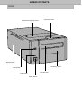
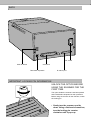
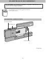
Hardware Manual
Thank you for purchasing the Minolta Dimâge Scan Multi II. The Dimâge Scan Multi II is a multiple format film scanner
capable of scanning medium format, 35mm, 16mm, and sleeved APS film. With the optional APS adapter, advanced
photo system film in the cassette can also be scanned.
Your new scanner has extraordinary features, including:
• Medium-format film scanning capability. The included medium-format film holder uses antinewton glass and
includes masks for 6x4.5, 6x6, 6x7, 6x9.
• 12-bit AD converter, so fine detail is captured with a dynamic range.
This manual has been designed to help you understand the operation of your scanner. To realize all the benefits of
your scanner, please read this manual and the accompanying software manual thoroughly.
The instructions in this manual assume you have a working knowledge of the operating system for your computer
(Mac OS, Windows 95, or Windows NT) and its conventions. Familiarity with the mouse and standard operating system
menus and commands is necessary before operating the Dimâge Scan Multi II software.
This manual does not instruct in the:
• basic use of personal computers.
• use of Window 95, Windows NT, or Mac OS.
• use of Adobe Photoshop, Paint Shop Pro, or Corel Draw.
Microsoft, Windows®, Windows 95®, and Windows NT® are registered trademarks of the Microsoft Corporation.
Macintosh™, Apple®, and Power Macintosh® are registered trademarks of Apple Computer, Inc.
Other corporate and product names are the trademarks and registered trademarks of their respective companies.
• Changes or modifications not approved by the party responsible for compliance could void the user’s authority to
operate the equipment.
• This manual may not be copied in part or whole without prior written permission from Minolta Co., Ltd. ©1998
Minolta Co., Ltd.
• Every necessary caution has been taken to ensure the accuracy of this instruction manual. Please contact us if you
have any questions, find any errors, or notice missing information.
• Minolta is not responsible for loss, damage, or other results occurring during the operation of this product.
This mark certifies that this product meets the requirements of the EU (European Union) concerning
interference causing equipment regulations. CE stands for Conformité Européenne.
This device complies with Part 15 of the FCC Rules. Operation is subject to the following
conditions: (1) This device may not cause harmful interference, and (2) this device must
accept any interference received, including interference that may cause undesired
operation.
Do not remove the ferrite cores from the SCSI cable.
This Class B digital apparatus complies with Canadian ICES-0003.
Cet appareil numérique de la classe B est conforme à la norm NMB-003 du Canada.
Tested by the Minolta Corporation
101 Williams Drive
Ramsey, New Jersey 07446
USA
FOR PROPER AND SAFE USE
Please read and understand each caution before using this product.
CAUTION
To avoid fire or electric shock:
• Only use the voltage specified for this unit.
• Do not expose this unit to liquids.
• Do not insert metal objects into this unit.
• Do not touch the cord or plug if your hands are wet.
• Unplug this unit when it is not in use.
Improper use of the power cord may result in fire or electric shock.
• Insert the plug securely into an electrical outlet.
• Do not pull on the cord. Grasp the plug when removing the power cord from an
outlet.
• Do not scratch, twist, modify, heat, or place a heavy object on the power cord.
• Do not connect the ground to a gas pipe, telephone ground, or a water pipe.
Improper grounding can result in electric shock.
This product must have sufficient ventilation while in use. Blocked ventilation ducts may cause
the unit to overheat, increasing the risk of fire.
• Do not use or store this product in dusty or very humid areas.
If there is smoke, a strange smell, or any other unusual conditions, shut down and unplug the
unit, then contact a Minolta Service Facility.
Do not attempt to disassemble this product. It contains high-voltage circuits. Take the
product to a Minolta Service facility for repairs.
Unexpected damage may occur if this unit is left unattended near young children.
1
TABLE OF CONTENTS
FOR PROPER AND SAFE USE ..................................................................................1
BEFORE YOU BEGIN
Package Contents.........................................................................................................4
System Requirements ..................................................................................................5
NAMES OF PARTS
Front..............................................................................................................................6
Back ..............................................................................................................................7
Important: Locking Pin Information ...............................................................................7
SETTING THE SCSI ID ................................................................................................8
CONNECTING TO THE COMPUTER
If the Scanner is the Only or Last Device in the Chain ................................................9
If the Scanner is Inside the Chain ................................................................................11
GETTING STARTED
Film Emulsion ...............................................................................................................14
Handling Care...............................................................................................................14
LOADING 35MM FILM HOLDERS
Slide Mount Holder SH-M1...........................................................................................15
35mm Film Holder FH-M1 ............................................................................................16
LOADING THE MEDIUM FORMAT FILM HOLDER MH-M1
Using the Medium Format Film Holder MH-M1............................................................18
Medium Format and TEM Film .....................................................................................18
16mm and APS Sleeve Film.........................................................................................20
Rotating the Frame .......................................................................................................22
INSERTING THE HOLDER INTO THE SCANNER......................................................23
Ejecting .........................................................................................................................23
APS ADAPTER AD-100 (SOLD SEPARATELY)...........................................................24
APS Adapter – Names of Parts....................................................................................24
Loading the Cassette....................................................................................................25
Inserting the Adapter ....................................................................................................26
Ejecting the Adapter .....................................................................................................27
CHANGING THE FLUORESCENT LAMP....................................................................28
IMPORTANT: BEFORE TRANSPORTING THE SCANNER ........................................30
TROUBLESHOOTING..................................................................................................31
2
INDICATOR LAMP........................................................................................................33
TECHNICAL DETAILS..................................................................................................34
CUSTOMER SERVICE.................................................................................................35
Minolta ..........................................................................................................................36
3
BEFORE YOU BEGIN
PACKAGE CONTENTS
CHECK THIS PACKING LIST BEFORE YOU BEGIN. IF SOME PARTS ARE
MISSING, CONTACT YOUR DEALER OR A MINOLTA SERVICE FACILITY.
• Minolta Dimâge Scan Multi II scanner
• 35mm Film Holder FH-M1
• 35mm Slide Mount Holder SH-M1
• Medium Format Film Holder MH-M1
• Film Masks:
6 x 4.5 Medium Format Film Mask
6 x 6 Medium Format Film Mask
6 x 7 Medium Format Film Mask
6 x 8 Medium Format Film Mask
6 x 9 Medium Format Film Mask
APS Sleeve Film Mask
16mm Film Mask
• Power Cord PW-M2
• SCSI Cable SC-11
• Dimâge Scan Multi II CD-ROM v1.0
• Instruction Manuals (1 software, 1 hardware)
• Warranty and Software Registration card
4
SYSTEM REQUIREMENTS
MACINTOSH
CPU: Power PC, Power Macintosh G3, Blue & White Power Macintosh G3 and Power Macintosh G4 (Except for 68 K
Macintosh and Mac OS compatible unit). Power Macintosh G4 is recommended when loading with 16 bit and using the
Digital ROC/GEM functions.
Operation System:
Memory:
Mac OS 7.5.3 to 9.0.4
A minimum of 32 MB (megabytes) application RAM in addition to the requirements for the
Mac OS.
256 MB or more when loading with 16 bit and using the Digital ROC/GEM functions.
Hard Disk Space:
About 600 MB or more of available hard disk space.
About 2 GB or more of available hard disk space when loading with 16 bit and using the
Digital ROC/GEM functions. (About 3 GB or more is recommended.)
Monitor:
Minimum 13 (640 x 480) inch monitor capable of displaying at least 32,000 Colors.
19 inch(1024 x 768) or larger is recommended.
CD-ROM Drive:
Necessary (when installing the software.)
Recommended SCSI Board:
With a Power Macintosh and Power Macintosh G3
The standard built-in SCSI board
Connecting to the extension board inserted into the PCI bus/NuBus is not available.)
With a Blue & White Power Macintosh G3*, Power Macintosh G4
Adaptec PowerDomain 2940UW/U2W, PowerDomain 2930U, SCSI Card 2906, and AVA2903B
* Some models in the Blue & White Power Macintosh G3 series use the Ultra2 Wide SCSI
board as the standard built-in SCSI board, however, connecting the Dimage Scan Multi II to
the standard built-in SCSI board is not recommended. The connecting capacity may be
limited and the full capabilities of the PC may not be usable due to the specifications of the
standard built-in SCSI board.
When using the model which has the standard built-in SCSI board, insert the
recommended SCSI board as described above in the open slot without detaching the
standard built-in SCSI board and then connect the Dimage Scan Multi II to the SCSI
connctor on the inserted SCSI board.
Other:
Adobe PhotoShop Ver. 4.0.1, Ver. 5.0.2, Ver. 5.5 and Adobe Photoshop 5.0 LE have been
fully tested for use with the plug-in software.
MACINTOSH
CPU:
IBM PC/AT compatible with an Intel Pentium processor 90 MHz or above.
• Support cannot be provided for custom or home built machines.
Pentium III Processor is recommended when loading with 16 bit or using the Digital
ROC/GEM functions.
Orerating System:
Windows®95 (inc. OSR2), Windows®98 (inc. Second Edition), Windows®2000
Professional, Windows®NT 4.0
Memory:
A minimum of 32 MB (megabytes) of RAM.
A minimum of 512 MB when loading with 16 bit and using the Digital ROC/GEM functions.
Hard Disk Space:
About 600 MB or more of available hard disk space.
About 2 GB or more of available hard disk space when loading with 16 bit and using the
Digital ROC/GEM functions. (About 3 GB or more is recommended.)
Monitor:
Minimum VGA (640 x 480) monitor capable of displaying High Color (16 bit) is required.
XGA (1024 x 768) or larger is recommended.
CD-ROM Drive:
Necessary (when installing the software.)
Recommended SCSI Board:
Adaptec AHA-1510B, AHA-1520B, AHA-1540CP, AHA-2910B, AHA-2910C, AHA-2920C,
AHA-2940, AHA-2940U/W/AU/UW/U2W, SCSI Card 19160/29160/29160N, AVA2902E/2903B/2906
Other:
Photoshop Ver. 3.0.5, Ver.4.0.1, Ver. 5.0.2, Ver. 5.5, Photoshop 5.0 LE, Paint Shop Pro Ver.
6, Corel PHOTO-PAINT Ver. 9* have been fully tested for use with the TWAIN driver
software.
*Corel Scan is not recommended.
5
NAMES OF PARTS
FRONT
Fluorescent lamp unit cover
Connector cover
Indicator lamp
Accessory panel
Eject button
Film-slot door
Power lamp
Power switch
BACK
AC socket
SCSI ID switch
Centronics
Terminator dip switch
D-sub-25 port
IMPORTANT: LOCKING PIN INFORMATION
UNLOCK THE OPTICS BEFORE
USING THE SCANNER FOR THE
FIRST TIME.
The optics inside the scanner have been parked
and locked before shipment for their protection.
Before using the scanner for the first time, unlock
the locking pin.
• Gently turn the scanner up-side
down. Using a flat-head screwdriver,
turn the locking pin counterclockwise until it pops up.
7
SETTING THE SCSI ID
The Dimâge Scan Multi II’s SCSI ID is factory preset to 5. If 5 is not being used by another operating SCSI device in
the SCSI chain, it is not necessary to change the SCSI ID.
A SCSI ID is a unique address you assign to each SCSI device connected to your computer. The SCSI ID range of
your computer is from 0 to 7, however some IDs are already occupied by your computer.
Occupied SCSI ID
IBM PC/AT:
7 (SCSI host adapter)
Macintosh:
0 (internal hard drive)*
3 (internal CD-ROM drive)**
7 (system)
* IDE Macintosh systems do not use SCSI ID 0 for the hard drive.
** Macintosh systems with a dual bus have SCSI ID 3 available on the external bus.
TURN OFF THE COMPUTER AND ALL THE SCSI DEVICES
BEFORE CHANGING SCSI IDS, CONNECTING SCSI
CABLES, OR DISCONNECTING SCSI CABLES.
TO CHANGE THE SCSI ID:
1. Turn off the computer and all connected SCSI devices.
2. Determine which SCSI IDs are not being used.
3. Change the SCSI ID using the upper or lower SCSI buttons.
Press the upper button to select a smaller SCSI number.
The current SCSI ID number.
Press the lower button to select a higher SCSI number.
8
CONNECTING TO THE COMPUTER
IF THE SCANNER IS THE ONLY OR LAST DEVICE IN THE CHAIN…
TURN OFF THE COMPUTER AND ALL THE SCSI DEVICES
BEFORE CHANGING SCSI IDS, CONNECTING SCSI
CABLES, OR DISCONNECTING SCSI CABLES.
One D-sub-25 to Centronics 50 cable is included with your scanner. Please see your dealer if you require a
different cable.
1. Connect one end of the SCSI cable to either
SCSI port on the back of the scanner.
• Either SCSI port can be used, there is no dedicated in or
out port.
2. Connect the other end of the SCSI cable to the
SCSI port on the computer or on the last SCSI
device in the chain.
3. Flip the dip switch marked 1 up to turn the
terminator on.
• Dip switches 2 through 4 are inactive. Their position will not
affect the scanner operation.
9
Continued on following page.
CONNECTING TO THE COMPUTER
4. Plug the power cord into the scanner’s AC
socket.
5. Plug the other end of the power cord into a
grounded outlet.
10
IF THE SCANNER IS INSIDE THE CHAIN…
TURN OFF THE COMPUTER AND ALL THE SCSI DEVICES
BEFORE CHANGING SCSI IDS, CONNECTING SCSI
CABLES, OR DISCONNECTING SCSI CABLES.
One D-sub-25 to Centronics 50 cable is included with your scanner. Please see your dealer if you require additional
cables.
The following is an example of one possible SCSI chain configuration.
Computer
SCSI Device 2
SCSI Device 1
Scanner
Cable “A”
Cable “B”
1. Connect one end of the SCSI cable A into
either SCSI port on the back of the scanner.
• Either SCSI port can be used, there is no dedicated in or
out port.
2. Plug the other end of SCSI cable A into SCSI
device 1.
11
Continued on following page.
CONNECTING TO THE COMPUTER
3. Connect one end of SCSI cable B into the
remaining SCSI port on the back of the
scanner.
4. Connect the other end of SCSI cable B into the
next device in the chain.
5. Flip the dip switch marked 1 down to turn the
terminator off.
• Dip switches 2 through 4 are inactive. Their position will not
affect the scanner operation.
6. Plug the power cord into the scanner’s AC
socket.
12
7. Plug the other end of the power cord into a grounded outlet.
length of
The total
in
SCSI cha
cable in a xceed 6m
te
should no ost
m
r
(20 ft.) fo
.
systems
13
GETTING STARTED
FILM EMULSION
The emulsion side of the film is the side coated with the photographic material. The base side of the film has no
photographic material and its surface is smooth and shiny. The emulsion side of slide film has raised areas at subject
contrast. The emulsion side of negative film is dull compared to the base side. It is easiest to determine the emulsion
side when viewing the film at an angle.
Light
Viewing angle
FILM EMULSION
Slightly dull or raised surface
FILM BASE
Smooth, shiny surface
The frame numbers and text are backward when the film’s emulsion side is up.
HANDLING CARE
• Do not pull the film holder out of the scanner until the holder is properly ejected and
the green indicator light is off.
• Do not move the scanner or touch the film holder while the transport motor is
engaged (such as while scanning).
• Place the scanner on a stable surface.
14
LOADING 35MM FILM HOLDERS
SLIDE MOUNT HOLDER SH-M1
• The slide mount holder can hold up to 4 mounted slides (35mm or APS).
• Slide mounts must be thicker than 1mm and thinner than 2mm to fit properly into the holder.
• Results of scanning glass-mounted slides can be unpredictable.
• Blow dust off the slide before placing it into the film holder.
1. Position the slide mount
holder so the white arrow is
on the top-left side, then open
the slide mount.
• Open the slide holder by pushing up
on the two tabs from underneath.
2. Place the slides within the
indentations, making sure
they lie flat.
• Insert the slides emulsion side down.
3. Press the cover firmly closed
until it clicks.
15
35MM FILM HOLDER FH-M1
Use the FH-M1 for 35mm negatives and unmounted 35mm slide film.
• The 35mm Film Holder FH-M1 can hold film strips up to 6 frames long.
• Blow dust off the film before placing it into the film holder.
1. Position the film holder so the
white arrow is on the top-left
side, then open the slide
mount.
• Open the slide holder by pushing up
on the two tabs from underneath.
2, Place the film in the film
holder emulsion side down.
3. Align the frames within the
scanning windows.
16
4. Press the cover firmly closed
until it clicks.
17
LOADING THE MEDIUM FORMAT HOLDER MH-M1
USING THE MEDIUM FORMAT HOLDER MH-M1
Use the MH-M1 for 120/220 film frames in 6x4.5, 6x6, 6x7, and 6x9 formats. The MH-M1 should also be used for
sleeved APS film, 16mm film, and TEM* film. Use the appropriate film mask for each film format. The glass in the
Medium Format Film Holder MH-M1 has been treated to prevent the appearance of Newton’s rings (coloured rings)
when scanning.
• Handle the Medium Format Film Holder MH-M1 with care. Protect the glass from impact, shock, and scratches.
• Touching the glass in the film holder may cause damage to the antinewton treatment.
• Blow away any dust from the film holder before inserting the film. If the film holder is dirty, first blow away any dust
or debris, then moisten a lens cleaning tissue with lens cleaning fluid and gently wipe the surface.
* Transmission Electron Microscope
MEDIUM FORMAT AND TEM FILM
1. Press on the lever marked
“PUSH”, then lift open the
holder.
2. Select the appropriate mask
and place it in the film holder
using the guides.
• The cut corner on the mask should be
on the bottom-left side.
• Choose the appropriate size mask for
TEM film.
Align the slot in the
mask with the rail
on the film holder.
Align the holes in the mask with the pins on the film
holder.
18
3. Place the film in the film
holder.
• Secure the film by placing it flush
against the rail on the film holder.
• Place the film emulsion side down
(p 14).
Secure the film by placing it flush
against the rail on the film holder.
4. Press the cover firmly closed
until it clicks.
erly
se a prop
Always u
e
sk with th
fitting ma
lm
fi
t
a
rm
medium fo mask or a
o
n
If
r.
holde
e is
is too larg
t
a
th
mask
will
t
h
acting lig
used, refr ge quality.
ima
degrade
19
16mm AND APS SLEEVE FILM
1. Press on the lever marked
“PUSH”, then lift open the
holder.
2. Place the APS Sleeve mask or
16mm mask on the film
holder.
Align the slot in the mask with the rail on the
film holder.
• The film guides on the mask should
be on the right side.
Align the holes in the mask with the pins on the film
holder.
20
Make sure the film lies flat between the
film guides.
3. Place the film in the mask
using the film guides.
• Place the film emulsion side down
(p 14).
Make sure the film lies flat between the
film guides.
4. Align the desired frame within
the scanning window.
5. Press the cover firmly closed
until it clicks.
erly
se a prop
Always u
e
sk with th
fitting ma
lm
fi
t
a
rm
medium fo mask or a
o
n
If
r.
holde
e
is too larg
t
a
th
mask
ht
g
fracting li
is used, re image
de
will degra
.
ty
quali
21
ROTATING THE FRAME
The image area of the Medium Format Holder MH-M1 can rotate 10 degrees in either direction to
compensate for a tilted image composition. By rotating the frame before scanning, the need to rotate the
scanned image, thus resampling the pixels, is eliminated.
1. Turn the holding screw
counter clockwise to
loosen it.
2. Rotate the carrier as
desired.
• Use the angle scale on the holder
for reference.
• With larger film formats, the
corners of the frame may not fit in
the scanning area when the
carrier is rotated.
3. Turn the holding screw
clockwise to secure it.
22
INSERTING THE HOLDER INTO THE SCANNER
1. Press the power switch to turn
the scanner on. Turn on your
computer, then launch the
Dimâge Scan Multi II software.
• The green indicator lamp will blink
slowly while the scanner is setting up.
2. Insert the holder into the
scanner in the direction
indicated by the white arrow
on top of the holder.
• Do not insert the holder at an angle.
3. Gently push the holder into
the scanner until the raised
insertion mark
is aligned
with the film-slot door.
• The film holder will be automatically
guided in past the
mark.
• If the holder is not loaded correctly,
then eject and reinsert it.
EJECTING
1. Press the eject button on the
front of the scanner.
• The holder will automatically eject
partway, then stop.
2. Remove the holder.
• Wait for the Indicator lamp to turn off
before removing the holder.
• The holder should pull out easily.
23
APS ADAPTER AD-100 (SOLD SEPARATELY)
• The APS Adapter AD-100 (optional accessory) is required to scan APS film in the
cassette with the Dimâge Scan Multi II.
Only processed film with the VEI set to
the APS Adapter AD-100.
can be inserted into
APS ADAPTER – NAMES OF PARTS
Film-chamber release
Film-chamber door
Scanner contacts*
* Do not touch
24
LOADING THE CASSETTE
1. Slide the film-chamber release as shown.
• The film chamber door will open.
2. Insert the film cassette into the film chamber
with the VEI on top.
• Only load cassettes displaying the
mark.
3. Close the film-chamber door.
• The film-chamber release will return to its start position
when the door is closed properly.
25
INSERTING THE ADAPTER
1. Press the power switch to turn
the scanner on. Turn on your
computer, then launch the
Dimâge Scan Multi II software.
• The green indicator lamp will blink
slowly while the scanner is setting up.
2. Pull the accessory panel on
the scanner straight out, then
open it all the way pushing it
until it clicks.
• Do not force the accessory panel.
• Do not open the accessory panel
during the set-up process. Wait until
set-up is complete and the indicator
lamp is off.
3. Insert the holder into the
scanner in the direction
indicated by the white arrow
on top of the adapter.
• Do not insert the adapter at an angle.
4. Gently push the adapter into
the scanner until the raised
insertion mark
is aligned
with the film-slot door.
• The adapter will be automatically
guided in past the
mark.
• If the adapter is not loaded correctly,
then eject and reinsert it.
26
EJECTING THE ADAPTER
1. Press the eject button on the
front of the scanner.
• The adapter will automatically eject
partway, then stop.
2. Remove the adapter.
• Wait for the Indicator lamp to turn off
before removing the adapter.
• The adapter should pull out easily.
• When the Eject button on the front of the scanner is used, the film will rewind into the cassette before the
adapter is ejected, regardless of the software Preference settings. Please refer to the Preferences section in the
software manual.
• If a film transport error occurs, do not use that cassette in the adapter. Contact a Minolta
Service Facility.
• Minolta is not responsible for damage to the cassette.
• With some camera models the images will appear up-side-down. Use the Rotate All
Frames 180˚ option in the Preferences. Please refer to the Preferences section in the
software manual.
27
CHANGING THE FLUORESCENT LAMP
When the indicator light is red and blinks rapidly, check to see of the fluorescent lamp is operational. Replace
the fluorescent lamp when it burns out. See your dealer to purchase a replacement lamp unit.
CAUTION:
Turn off the scanner and allow the unit to cool for 10 minutes
before removing the fluorescent lamp.
1. Remove the fluorescent lamp
unit cover.
2. Pull up the locking bar.
3. Press on the release tab on
the plug and disconnect the
old lamp.
28
4. Connect the new lamp.
• Snap the connectors together until they click.
5. Place the lamp unit in the scanner
by aligning the raised edge of the
lamp unit 1 with the rectangular
notch 2 on the scanner.
• The arrows on the lamp and scanner should
be lined up.
• The lamp unit will not slide from side to side if
it is inserted correctly.
6. Hold the lamp unit in place and
replace the locking bar.
7. Replace the fluorescent lamp unit
cover.
29
IMPORTANT: BEFORE TRANSPORTING THE SCANNER
Before transporting the scanner the optics must be parked and locked into place to prevent damage.
1. With the Dimâge Scan Multi II software active (utility, TWAIN driver, or plug-in):
Windows: press Ctrl + Shift + L.
Macintosh: press Command + Shift + L.
2. The message informing you the optics will be moved will appear. Click on OK.
3. After the optics have been moved, a message will appear asking you to turn the
scanner off. Click on OK.
• The utility software will quit.
4. Turn off the computer.
5. Turn off the scanner and other SCSI devices.
6. Gently turn the scanner up-side down. Using a flat-head screwdriver, push down
and turn the locking pin clockwise until it locks down.
• Once the optics have been moved to the locking position through the software, the scanner must perform
the set-up operation to return to normal. The scanner automatically performs set-up when it is first turned
on. Set-up can also be initiated by pressing the following keys simultaneously while the software is active:
Windows95/NT: Control + Shift + i
Macintosh: Command + Shift + i
30
TROUBLESHOOTING
Symptom
Cause/Action
The computer will not start after connecting
the scanner.
Check that all the SCSI cables are secure.
The computer does not recognize the
scanner.
Was the scanner turned on before the
computer was turned on?
Reference
Page 8
Check that two SCSI devices are not sharing
the same address.
Check that all the SCSI cables are secure.
Windows 95/NT: Check that the SCSI device
driver been installed correctly.
1. Select Start ‘ Settings ‘ Control Panel.
• The Control Panel window will appear.
2. Double-click on the System Icon, then click
on the Device Manager tab.
3.Click on the plus (+) next to
“SCSI controllers”.
• A sub-menu of SCSI controllers should
appear.
4. Confirm the appropriate SCSI Controller for
your board is listed in the sub-menu.
The scanner does not pull in the film holder
when loading
Eject, then reinsert the holder.
The scanned image is very green or blownout white when using the Medium-format
holder.
The mask does not fit the image properly. Be
sure to use a proper fitting mask that is not too
big for the image. There should be no
uncovered space between the film and the
mask.
The indicator lamp glows red.
If using a film holder:
The film holder must be inserted to the
marks for it to be engaged by the scanner’s
motor
Pages 18 -21.
The accessory panel is open. Close the
accessory panel.
If using the APS adapter:
The accessory panel is not fully open.
Open it all the way and push it until it
clicks.
31
Continued on following page.
Page 26.
TROUBLESHOOTING
Cause/Action
Symptom
The indicator lamp is red and blinks rapidly
or
The scanned image is black.
The scanned image colour is strange.
1. Turn off the computer, then the scanner.
Check that the fluorescent lamp cover is
closed.
2. Turn on the scanner. If the fluorescent
lamp does not glow, replace the lamp.
3. If the cover was closed, the fluorescent
lamp works, and the red lamp continues
to blink rapidly, there is a hardware
problem. Turn off and unplug the scanner,
then call a Minolta Service Facility.
Check that there is no dust on the film or film
holder.
Check that the colour palette (START –
SETTINGS – CONTROL PANEL – DISPLAY
– SETTINGS) is on High Colour (16 bit) or
higher. Different or additional steps may be
necessary depending on your graphics board.
Refer to your graphics board‘s documentation.
If using the Medium-format holder, be sure to
use a proper fitting mask. If the holder is dirty,
clean it as directed.
Reinitialize the scanner.
Windows 95/NT: Press Control, Shift, and i
keys simultaneously.
Macintosh: Press Command, Shift, and i keys
simultaneously.
Reinitializing while using the APS adapter:
1.
2.
3.
4.
5.
•
Press the initialization key combination.
The adapter will eject automatically.
Initialization (set-up) will stop.
Remove the adapter.
Close the accessory panel.
Initialization (set-up) will resume.
32
Reference
Page 28.
INDICATOR LAMP
The indicator lamp on the front of the scanner reveals the status of the scanner.
Indicator Lamp
Scanner Status
Off
Set up is complete and there is no holder
inserted in the scanner.
Green – blinking slowly
Scanner is busy:
• setting up (initializing).
• index scanning, prescanning, or scanning.
• autofocus, point AF, manual focus.
Green – blinking quickly
If using a film holder, the scanner is busy:
• loading the film holder.
• transporting the film holder.
• ejecting the film holder.
If using the APS Adapter, the scanner is busy:
• rewinding the film in the APS adapter.
• transporting the adapter.
Green – glows steadily
There is a film holder in the scanner. The
scanner is not busy.
Red – glows steadily
There is a problem with the accessory panel.
If using a film holder:
The accessory panel is open. Close the
accessory panel.
If using the APS adapter:
The accessory panel is not fully open.
Open it all the way and push it until it clicks.
Red – blinks quickly
The fluorescent lamp unit cover is not fully
closed.
or
The fluorescent lamp is burnt out.
or
There is a hardware malfunction. Contact a
Minolta Service facility.
33
TECHNICAL DETAILS
Type:
Film transport, fixed sensor, 1 pass scan film scanner
Usable Film:
Medium format film (6x4.5, 6x6, 6x7, 6x8, 6x9) – positive/negative, colour/B&W;
35mm film - positive/negative, colour/B&W;
Transmission Electron Microscope film – (5.9 x 8.2cm) positive/negative,
colour/B&W;
16mm film – positive/negative, colour/B&W;
APS sleeve film – positive/negative, colour/B&W
APS Casette (with optional adapter) – positive/negative, colour;
Scanning Dimensions:
35mm
6 x 4.5
6x6
6x7
6x8
6x9
TEM
APS
16mm
Optical Input Resolution:
2820dpi: 35mm, APS, and 16mm film
1128dpi: Medium format and TEM film
A/D Conversion:
12-bit
Image Sensor:
RGB 3-line CCD (2700 pixels)
Continuous Scan Max.:
35mm Sleeved: 6 frames
35mm Mounted: 4 frames
APS Cassette (requires optional accessory): 40 frames
35mm Mounted with optional Slide Feeder: 50 frames
Interface:
SCSI-2
SCSI Ports:
D-Sub 25 pin, Centronics 50
Light Source:
Hot cathode fluorescent lamp, 3 wavelength, user replaceable.
Power/Frequency:
AC 100 – 240V, 50/60Hz
Dimensions:
(w)200 x (d)410 x (h)124mm (7.9 x 16.1 x 4.9 in.)
Weight:
Approximately 6kg (211.8 oz)
24.20
56.16
56.16
56.16
56,16
56.16
56.16
17.28
13.00
x
x
x
x
x
x
x
x
x
36.30mm
41.76mm
56.16mm
64.80mm
78,08mm
83.52mm
82.00mm
29.95mm
19.50mm
2688
2496
2496
2496
2496
2496
2496
1920
2688
x
x
x
x
x
x
x
x
x
4032
1856
2496
2880
3472
3712
3712
3328
4032
pixels
pixels
pixels
pixels
pixels
pixels
pixels
pixels
pixels
Specifications are based on the latest information available at the time of printing and are subject to change without
notice.
34
CUSTOMER SERVICE
Please contact your dealer regarding installation, SCSI interface recommendations, or application compatibility. If
your dealer is unable to help you, contact us toll free.
Technical Support
1-800-808-4888
Monday – Friday 8:30-5:00 (EST)
Minolta Corporation
101 Williams Dr.
Ramsey, NJ 07446
(201) 825-4000i
Please have the following information ready when calling Minolta Technical Support:
Make and model of your computer:
Available application RAM:
Operating system and version:
Other connected SCSI devices and their SCSI ID numbers:
DS Multi II software version number:
Symptoms:
Messages that appear on the screen when the problem occurs:
Frequency of occurrence:
To determine the version number of your driver software:
Place the pointer over the Status Bar in the Command window. The version number will be displayed in the
status window.
35
A
Minolta Austria Ges.m.b.H
Amalienstr. 59-61, A-1131 Wien, Österreich
Tel:01 87868 176
Fax:01 87868 153
http://www.minoltaeurope.com
B
Minolta Belgium Branch
Prins Boudewijnlaan 1
B-2550 Kontich, België
Tel: 03 451 07 00
Fax: 03 458 50 48
http://www.minolta.be en http://www.minolta.nl
CAN Minolta Canada Inc., Head Office
369 Britannia Road East,
Mississauga, Ontario L4Z 2H5, Canada
Tel.0905 890 66 00
Fax0905 890 71 99
http://www.minolta.com
CH Minolta (Schweiz) AG
Riedstr. 6, CH-8953 Dietikon, Schweiz
Tel:157 57 11 (sFr 2.15/min)
Fax:01 741 33 12
http://www.minolta.ch
D
Minolta Europe GmbH
Minoltaring 11,
D-30855 Langenhagen,
Deutschland
Reparatur/Repair
Senator-Helmken-Strasse 1,
D-28279 Bremen,
Deutschland
Hotline: Tel: 0221 5 60 60 31
Fax: 0221 5 60 60 40
DK
E
F
http://www.minolta.de
Paul Westheimer A/S
Erhvervsvej 30, DK-2610 Rødovre, Danmark
Tel:44 85 34 00
Fax:44 85 34 01
http://www.minoltaeurope.com
Videosonic S.A.
c/ Valportillo II, 8, Pol. Ind. de Alcobendas,
E-28108 Alcobendas/Madrid, Spain
Tel:91 4840077
Fax:91 4840079
http://www.minoltaeurope.com
Minolta France S. A.
365, Route de Saint-Germain,
F-78420 Carrières-Sur-Seine, France
Tel:0130 86 62 37
Fax:0130 86 62 82
http://www.minolta.fr
FIN Minolta Finland Branch
Niittykatu 6, PL 37 SF-02201 Espoo, Finland
Tel:435 565 0
Fax:435 565 56
http://www.minolta.fi
GB Minolta (UK) LTD. Photographic Division
Precedent Drive,
Rooksley, Milton Keynes, MK13 8HF, England
Tel:01 908 208 349
Fax:01 908 208 334
http://www.minoltaeurope.com
IRL Photopak Sales
241 Western Industrial Estate, Naas Road,
Dublin 12, Ireland
Tel:01 45 66 400
Fax:01 45 00 452
http://www.minoltaeurope.com
I
Rossi & C. S.p.A.
Via Ticino 40,
I – 50019 Osmannoro Sesto Fiorentino (Fi),
Italy
Tel.:055 323141
Fax:055 32314252
http://www.minoltafoto.it
N
Scandiafilm AS
Enebakkveien 304, N-1188 Oslo 11, Norge
Tel:022 28 00 00
Fax:022 28 17 42
http://www.minoltaeurope.com
NL Minolta Camera Benelux B.V.
Zonnebaan 39, Postbus 6000
3600 HA Maarssen, Nederland
Tel: 030 247 08 09
Fax: 030 247 08 88
http://www.minolta.nl
P
Minolta Portugal Lda
Av. do Brasil 33-a, P-1700 Lisboa, Portugal
Tel:01793 00 16
Fax:01 793 10 64
http://www.minoltaeurope.com
S
Minolta Svenska AB
P. O. Box 9058, Albygatan 114, S-17109 Solna,
Sverige
Tel:08 627 76 50
Fax:08 627 76 21
http://www.minoltaeurope.com
Sin Minolta Singapore (Pte) Limited
10 Teban Gardens Crescent, Singapore 2260
Tel:56 35 533
Fax:56 10 217
http://www.minolta.com
36
37