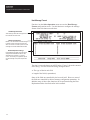
1
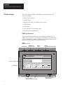
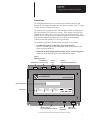
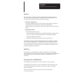
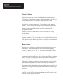
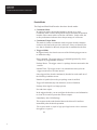
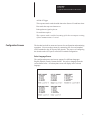
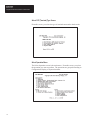
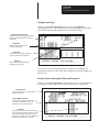
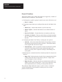
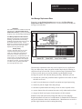
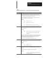
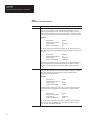
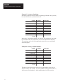
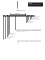
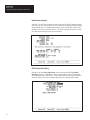
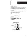
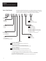
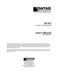
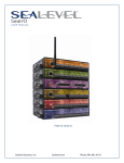
A–B ALLEN-BRADLEY Single/Dual-Head Enhanced Bar Code Decoders (Catalog No. 2755-DS1A,-DS4A,-DD1A,-DD4A) Series B Product Data Overview. The Enhanced Bar Code Decoders are available in a variety of configurations providing application flexibility. For example, the single-head decoders (Catalog No. 2755-DS1A or -DS4A) have one scanner port while the dual-head decoders (Catalog No. 2755-DD1A or -DD4A) have two. Plus, each decoder is available in a NEMA Type 1 or Type 4 enclosure. Other options available for each decoder include: • LCD Display • I/O Module Board supporting up to eight output modules You can order these options with the decoder or as separate components for customer installation. In addition, Allen-Bradley offers a full line of accessories to support the decoders including scanners, package detectors, and cables. Product Data Bulletin 2755 Single/Dual-Head Enhanced Bar Code Decoders Decoder Features This section describes features of the Single and Dual-Head Bar Code Decoders including: • NEMA Type Enclosures • Scanner Port(s) • Integrated 100-240V AC (nominal) Power Supply • LED Indicators • LCD Display • AUX and HOST Communication Ports • Discrete Input/Output Modules NEMA Type Enclosures The Single and Dual-Head Decoders are available in a NEMA Type 1 or NEMA Type 4 enclosure. All connections on the NEMA Type 4 enclosure comply with NEMA 4 standards. Although the installation differs for each they have the same features and operate identically. Figure 1 NEMA Type 1 Version POWER SCANNER A Port SCANNER B Port (DD Versions Only) AUX Port RS-232 ALLEN-BRADLEY HOST Port RS-232/422 &485 w/DH485 Protocol BAR CODE DECODER Optional LCD Display LED Indicators POWER CPU ACTIVE COMMUNICATION LASER ON A TRIGGER ACTIVE A VALID READ A LASER ON B TRIGGER ACTIVE B VALID READ B Holes for Conduit or Optional Output Module Connectors 2 DISCRETE I/O 1 2 3 4 5 6 7 8 IEC 320 Power Connector and ON/OFF Switch Product Data Bulletin 2755 Single/Dual-Head Enhanced Bar Code Decoders Scanner Ports The Dual-Head Decoder has two scanner ports, labeled Scanner A and Scanner B. The Single-Head Decoder has only the Scanner A port.➀ Figures 1 and 2 show the location of the ports. The scanner ports support all of the Allen-Bradley medium and high speed bar code scanners (see Accessories section). The scanners do not require a separate power supply; they receive power directly from the decoder. The NEMA Type 1 version of each decoder also supports all of the Allen-Bradley stop and scan Visible Laser Diode (VLD) fixed mount and hand-held scanners when used with the 2755-NC16 gun adapter. The scanners on the Dual-Head Decoders can operate in two modes: • Coordinated Mode (Coordinated 1 and Coordinated 2) Scanners A and B operate in a coordinated mode, each using the same trigger source (Scanner A). • Independent Mode (Independent Package Detect or Host Triggered) Scanner A and Scanner B operate with independent triggers. Figure 2 NEMA Type 4 Version SCANNER B Port SCANNER A Port (DD Versions Only) AUX Port RS-232 ALLEN-BRADLEY HOST Port RS-232/422 &485 w/DH485 Protocol BAR CODE DECODER Optional LCD Display LED Indicators POWER CPU ACTIVE COMMUNICATION LASER ON A TRIGGER ACTIVE A VALID READ A LASER ON B TRIGGER ACTIVE B VALID READ B Holes for Conduit or Optional Output Module Connectors DISCRETE I/O 1 2 3 4 5 6 7 8 ON/OFF Toggle Switch NEMA Type 4 Power Connector ➀ The Single-Head Decoder cannot be upgraded to include a second port. 3 Product Data Bulletin 2755 Single/Dual-Head Enhanced Bar Code Decoders Power Supply An internal power supply provides power to the scanners and the decoder. The source voltage may range from 100 to 240 volts AC nominal (50 to 60 Hz). The power supply automatically adjusts to the input voltage. LED Indicators Front panel indicators provide a visual indication of the operating status of the decoders. Figures 1 and 2 show the location of the LED indicators. Table 1 defines the color and function of each LED. Table 1 LED Indicators LED Label➀ Power CPU Active Color Green Green Communication Laser On A Trigger Active A Valid Read A Laser On B Trigger Active B Valid Read B Discrete I/O (1-8) Yellow Red Yellow Green Red Yellow Green Red Function Lights when the decoder is receiving power. Lights when the CPU is active and running. The LED turns off if a fault condition is detected. Lights when data is transmitting to or from the AUX port or HOST port. Lights when Scanner A is activated to turn on its laser light source. Lights when the decoder is in triggered mode and scanning has been triggered. Lights when a valid read occurs from Scanner A. Lights when Scanner B is activated to turn on its laser light source.➁ Lights when the decoder is in triggered mode and scanning has been triggered.➁ Lights when a valid read occurs from Scanner B.➁ Lights when an input or output module in position 1,2, 3, 4, 5, 6, 7, or 8 is closed. ➀ LED labels are available in five different languages. ➁ These LED indicators are not included with the Single-Head Decoder. LCD Display The decoders support an optional 2 line x 20 character per line alphanumeric LCD Display for on-line viewing of: • Bar code data • Output counter values • Decoder performance values The format of the display data is under user control via the configuration screens or host commands. The LCD Display can be ordered with the decoder or as a separate component for customer installation. Figures 1 and 2 show the location of the LCD Display. 4 Product Data Bulletin 2755 Single/Dual-Head Enhanced Bar Code Decoders AUX Port The AUX port communicates with a standard ASCII terminal using the RS-232 interface. This terminal is referred to as the AUX terminal. The AUX port can switch between two modes of operation. • Decoder Configuration The ASCII terminal is used to access built-in setup menus to configure and monitor decoder operations; format and configure host communications; and display bar code data, output counters and decoder status. • Manual Data Entry The ASCII terminal is used to: – enter data at the keyboard when the unattended scanners cannot read a label. This feature is useful when labels are damaged or missing. – display messages from the host. – display bar code data, output counters and decoder status. The decoder features an AUX Terminal jumper on the main logic board to switch between configuration and manual data entry operations. Another way to switch between these two modes is to connect specific pins in the AUX port connector. The port and logic board jumpers are initially set for decoder configuration operations. HOST Port The HOST port supports RS-232, RS-422, and DH485 (Allen-Bradley multidrop interface). The HOST port allows the exchange of commands and data between the decoder and a host computer or Allen-Bradley PLC controller. Power Connector and On/Off Switch The NEMA Type 1 decoder uses an IEC 320 power entry connector. The NEMA Type 4 decoder uses an environmental 3-pin connector with a separate ON/OFF toggle switch (that is sealed to comply with NEMA Type 4 standards). The power cords available for each decoder are listed under the Accessories Section. 5 Product Data Bulletin 2755 Single/Dual-Head Enhanced Bar Code Decoders Discrete I/O Modules The decoders support an optional I/O Module Board (eight positions for outputs with one position alternately accepting an input). With the optional I/O modules, the decoder can be used to control external AC or DC devices. Conditions that activate the outputs are under user control via the configuration screens or host commands. All positions accept an output module. Position 8 also excepts an input module. You can configure the decoder to automatically load scanned bar code data into the match code table. The input module (in position 8) can be used to reset the autoload data without using host commands or the configuration terminal. Each decoder has two conduit holes or optional connectors for wiring the I/O modules. The I/O Module Board is available in several variations for factory or customer installation. You can order the decoder with the I/O Module Board only, for customer installation of specific modules, or with 2 DC outputs and 1 DC input for ”out of the box” applications. Each option is listed under the Accessories sections. Memory Backup The decoders are designed to retain configuration during short term power interruptions. Controlled discharge of an on-board capacitor supports configuration retention for 6 hours at an ambient temperature of 50C (122F), or 50 hours at 30C (86F). The capacitor accumulates a charge when power is restored. An optional battery (catalog number 1747-BA) may be used to retain the configuration without outside power for up to five years. When the optional battery is used, power interruptions (whether intentional or resulting from power supply “glitches”) will have no affect on operating memory. If the battery is not used, long term power loss (see above) will result in the loss of the Extended Match Code Table configuration, the Primary and Extended Match Code Counters, and the text examples contained in the Host Replacement Rules. Note that the Replacement Rules themselves will not be lost, but the test examples you have entered at the bottom of each rule page will be lost. Storage memory configuration is transferred into operating memory on restart if power is lost for a period longer than the on-board capacitor (and, if installed, optional battery) can support. 6 Product Data Bulletin 2755 Single/Dual-Head Enhanced Bar Code Decoders Decoder Functions The decoder acquires and decodes bar code data from one or two scanners. The decoder can then: • send the decoded data to a host device (computer, PLC or SLC), ASCII terminal, or LCD display • apply Host Replacement Rules to incoming data, and send the result to a host device • compare the decoded data to data stored in the Primary or Extended match table and use the results to operate up to eight discrete outputs. The decoder also maintains counters for package count, no-reads, and discrete output operations. Symbologies The decoders support the following bar code symbologies: • Code 39 • UPC-A and UPC-E including optional 2 or 5 digit supplements • EAN-8 and EAN-13 including optional 2 or 5 digit supplements • Code 128 • Codabar • Interleaved 2-of- 5 • PharmaCode (Available in DS1P, DS4P, DD1P, or DD4P decoders) • Other symbologies in future product releases. Operating Modes When configuring the decoder, you can select from several operating modes. This section gives an overview of the different modes of operation. Scanning Modes The Dual-Head Decoder supports two scanning modes: • Coordinated Mode Scanner A and Scanner B are coordinated, using the same trigger source and set of configuration parameters. • Independent Mode Scanner A and Scanner B operate independently, each using a separate trigger source and set of configuration parameters.➀ ➀ Some parameters, such as Capture Count, Symbols per Scan, and Symbols per Package are shared in independent mode. 7 Product Data Bulletin 2755 Single/Dual-Head Enhanced Bar Code Decoders Decode Modes The Single and Dual-Head Decoders have three decode modes: • Continuous Mode In continuous mode, the decoder attempts to decode every scan. Continuous mode is useful during initial setup to determine the optimum location of the scanner relative to the bar code labels. In this mode, the on-line performance indicator shows the percentage of valid scans. • Continuous/Unique Mode This mode is similar to continuous mode except the decoder compares each new valid read to the previous valid read. If they are identical, the new data is discarded so that only unique data is transmitted to the host. • Triggered Mode In triggered mode, the decoder uses one of the following trigger sources to initiate decoding: Host Command. The trigger source is a command generated by a host computer or programmable controller. Package Detect. The trigger source is a package detector connected to the scanner. Internal Timer. The trigger source is an internal timer that cycles the trigger on and off at a set time interval. Once triggered, the decoder continuously decodes bar codes until one of the following conditions occurs: Number of symbols (bar codes) per package count is satisfied. Trigger off command (stop scan character) received from host. Package detect signal is no longer present. No-read timer expires. In the triggered mode, you can configure the decoder to send information to a host device and/or operate the discrete outputs: Immediately After Valid Package This response mode sends decoded data to the discrete I/O and host immediately after the decode operation. This response mode is useful in high speed applications where maximum throughput is required. or 8 Product Data Bulletin 2755 Single/Dual-Head Enhanced Bar Code Decoders At End of Trigger This response mode sends decoded data to the discrete I/O and host when: Host sends the stop scan character or Package detect signal expires or No-read timer expires. This response mode is useful when timing of the discrete outputs or timing of host communications is critical. Configuration Screens The decoder has built-in menus and screens for configuration and monitoring operations. You access these menus by connecting one of several standard ASCII terminals to the AUX port of the decoder. The process of configuring the decoder at the AUX port is called AUX terminal configuration. Select Language Screen The configuration menus and screens support five different languages: English, Spanish, French, German, Italian. You select a language from the screen shown below. All subsequent screens will display in the selected language. 9 Product Data Bulletin 2755 Single/Dual-Head Enhanced Bar Code Decoders Select CRT (Terminal) Type Screen From this screen, you select the type of terminal connected to the decoder. Select Operation Menu The Select Operation screen is the main menu. From this screen, you select the operation you want to perform. The operations are grouped according to Configuration, Display, or System functions. 10 Product Data Bulletin 2755 Single/Dual-Head Enhanced Bar Code Decoders Configure Symbology Option 1 on the Select Operation menu accesses the Symbology configuration screen. Use this function to select symbologies for decoding and to define the operating parameters to use during decoding. Symbology/Length Checking Enable and disable symbologies for decoding, and help assure data integrity and optimum performance Supplements Enable or disable supplements for UPC/EAN symbologies. PharmaCode (PharmaCode versions only) provides full control for all PharmaCode variables. Verification Enable verification of guard bars with Interleaved 2-of-5 symbols. The decoder will auto discriminate between multiple symbologies. For optimum performance, enable only those symbologies and code lengths you intend to use. Scanner Control, Primary Match Table, and Discrete I/O Option 2 on the Select Operation configuration screens. Use this function to configure scanner control, match codes, and discrete I/O operations. Scanner Control Control the operation of Scanner A and B (for Dual-Head Decoders). Primary Match Code Table Holds up to eight (1-8) match code entries. You can define the symbology and up to 32 characters for each match code string. Discrete I/O Controls the state (normally opened or normally closed) of the output modules, defines the source of the data (Dual-Headed Decoders only) and allows you to configure one of 11 conditions that will activate each output for a set duration. 11 Product Data Bulletin 2755 Single/Dual-Head Enhanced Bar Code Decoders Discrete I/O Conditions The Primary Match Code Counters and Outputs are triggered by a number of different events or conditions. These include: • Verifying that a symbol or group of symbols was read or failed to be read S Read or No-Read. • Comparing scanned data to pre-configured data stored in the Match Code Table S Match Entry – Scanned data matches a specific table entry. S Match Complete – Scanned data matches a user-defined number of entries. S Read and No-Match – Scanned data does not match any table entry S No-Read or No-Match – Either no symbol data was decoded (perhaps due to a damaged or missing label) or the decoded data did not exist in the table. • Configuring the Match Code Table by scanning bar code symbols S Autoload – Allows the scanned data from the first package read to be automatically entered into the match code table. Subsequent matches to the original data will activate outputs. S Autoload Input – Allows an operator to load new data into the match code table by activating a discrete input module (through a push button, key switch, or PLC output for example), and scanning a bar code symbol. • Monitoring host communication flow to throttle product flow and prevent data loss S Buffer Full – Indicates that the decoder’s host communications buffer is filling faster than data is being taken by the host. Output can be used, for example, to slow a conveyor. S Buffer Overflow – Indicates that the host communications buffer was unable to store all the incoming data. Can be used to shut down a line until communications are restored, preventing further data loss. The parameter None disables the output, or can be used as a “dead man” switch (with normally closed contact) to indicate power loss or other problem with the decoder. 12 Product Data Bulletin 2755 Single/Dual-Head Enhanced Bar Code Decoders Extended Match Table and Counters You can use the screen illustrated that follows to set up match code entries in the Extended Match Code Table. You can define up to 128 entries here that provide added flexibility in response to incoming data over the Primary Match Codes described in the previous chapter. Using Extended Match Codes you can compare all incoming data against table entries that you create to meet your own unique needs. The decoder can then count valid matches, and optionally fire one or more outputs. Extended Match Codes provide a way to gather extremely detailed information based on decoder activity, and to exercise an additional level of control over decoder output activities. The Extended Match Codes differ from the Primary Match Codes in a number of ways • • Extended Match Code counters appear on the same screen from which they are controlled (the primary counters appear on a separate Status and Primary Counters screen) Extended Match Codes can activate multiple outputs, the duration of which are defined in the Primary Match Code Table (Primary Match Codes can each fire only a single output). This screen displays the extended match code table in eight sets of sixteen entries. Set one includes entries 1 through 16, Set 2 includes 17 through 32, and so on. The entry numbers (1 through 128) appear on the left side of the screen. Screen Status Parameters provide updates status, resetting options, and access to all 128 extended match code entries. Each set of 16 entries can be individual enabled or disabled. Extended Match Code Table 128 entries arranged in 8 screens of 16 each. The operating mode, scanner source, bar code symbology, as well as the 32-character match table string are configured here. Loading Counts Individual counts and outputs are displayed here. Each match can be simply counted, or may additionally fire up to 8 discrete outputs. Outputs may be fired together or in a round robin sequence with each match. 13 Product Data Bulletin 2755 Single/Dual-Head Enhanced Bar Code Decoders AUX and LCD Display Parameters The decoder can display the following on an auxiliary terminal or an optional 2 line x 20 character per line alphanumeric LCD display to monitor: • • • • bar code data output counters decoder performance values host messages The AUX terminal and LCD display can each display bar code data, output counter values and decoder performance indicators. The parameters on the screen shown below control how this data is formatted. 14 Product Data Bulletin 2755 Single/Dual-Head Enhanced Bar Code Decoders Host Message Replacement Rules Function 5 on the Select Operation menu accesses the Host Message Replacement Rules configuration screen. Use this function to modify the message sent to the host. Rule Status Each number represents an available host message replacement rule. Currently enabled rules are marked with an asterisk ( * ), Rules are enabled by assigning a value to the Find String Containing field. Host Message Replacement Rule Definition Displays the current search rule criteria (Source, Symbology, Symbol Number, and Find String Containing) and the replacement string to send to the host when matches are found. The rule definition also includes parameters to fix the field length, character used to “fill” the field, and the alignment of the string within the field. Example Testing Provides a “worksheet” where you can insert sample bar code strings to test your rules. Allows you to “debug” your replacement rule expressions for structural and logical errors before going on-line. Just input the test bar code string on the left. The string that appears in the host message after application of the displayed rule appears on the right. If your test string does not create a match, you will be notified of that fact on the right side of the screen. Host message replacement rules may not be required in every application. They are unnecessary when your needs include simple object counting, or collection of raw bar code data. However, host message replacement rules will prove useful when you need to substitute a predetermined output message for specific bar code data during decoding. With them you can: • • • • • • send data in a particular, predefined order regardless of the order in which the labels were read mask bar code characters to simplify operations and speed processing truncate or pad the length of the data package substitute a predetermined text string for one or more expected values convert abstract bar code contents into more easily understood text form categorize labels based upon selected portions of their contents. Both the search and replacement strings that make up a Host Message Replacement Rule can consist of a combination of standard ASCII characters and special characters known as metacharacters. Metacharacters are used to perform logic functions on the incoming data string. 15 Product Data Bulletin 2755 Single/Dual-Head Enhanced Bar Code Decoders Metacharacters The decoder provides a complete set of special purpose characters you can use to perform logical functions on characters, expressions, or even entire strings. These characters are known as metacharacters. Metacharacters are string manipulation commands consisting of standard ASCII characters which you can embed within search or replacement strings. Each metacharacter conveys a specific instruction to the decoder software, and acts upon a clearly defined range within the string. Metacharacters can be used with standard alphanumeric characters to describe and manipulate even the most complex substitution scenarios with ease. Table 2 Search Pattern Metacharacters – Position Dependent Character Description and Use Note: The following two metacharacters are position-dependent. They must appear in the location specified to be matched. ^ $ . If the circumflex ( ^ ) is used as the first character in the search pattern, it indicates that the characters, other metacharacters, expressions, or strings must occur at the beginning of the string to be matched. Note that the circumflex has a special meaning if used within square brackets, as explained elsewhere in this chapter. When the dollar sign is used as the last character in the search pattern, it indicates that the characters, other metacharacters, expressions or strings must occur at the end of the string to be matched. The period represents any single character, and is used as a single-character “wildcard”. Note: These metacharacters refer to the character, metacharacter, string, or expression that immediately precedes them. 16 ? The question mark instructs the rule to match either no occurrence or one occurrence of what precedes it. This metacharacter is used in a search string where the character may not appear at all, or may appear once. + The plus sign instructs the rule to match one or more occurrences of what precedes it. This metacharacter is used in a search string where the character will be present, but you are unsure how many times it appears. * The asterisk instructs the rule to match none or more occurrences of what precedes it. This metacharacter is used in a search string in cases where the character may not appear, or may appear one or more times. Product Data Bulletin 2755 Single/Dual-Head Enhanced Bar Code Decoders Table 3 Search Pattern Metacharacters – Logical Operators and Other Special Functions Character Description and Use [ ] Square brackets ( [ ] ) instructs the rule to match an incoming string if any character enclosed within the brackets appears in the string. A range of values can be represented within the brackets by separating the first and last characters in the range by a hyphen. Square brackets must be used in pairs. Note: The circumflex ( ^ ) can be used as the first character within the square brackets to reverse the sense of the expression. Examples ( ) [ABC] Matches “A”, “B”, or “C” [L–P] Matches “L”, “M”, “N”, “O”, or “P” [0 – 9] Matches “0”, “1”, “2”, “3”, “4”, “5”, “6”, “7”, “8”, or “9” [^A – Z] Matches any character that is not upper case alphabetic Parentheses can be used in two different ways. They can be used in search patterns to group characters and metacharacters to form expressions. Parentheses must be used in pairs. Examples (AB)+ The plus sign applies to the expression (AB). Strings that would match this expression include: “AB”, “ABAB”, “123AB”, and “AB123”. Parentheses can also be used to identify strings for use in the Replace Entire String With field. If a character, string, or expression is surrounded by parentheses in a search pattern, then it can be later recalled in a replace pattern with the “\n” metacharacter described elsewhere in this chapter. Note: Parentheses may be nested to form complex expressions. | A vertical bar (the shifted “\” character on the keyboard) instructs the rule to match an incoming string if the character or expression on the left or right of the vertical bar appears in the string. Examples \ A|B Matches “A” or “B” abc|123 Matches “abc” or “123” The backslash indicates that the following character, which would normally be interpreted as a metacharacter, should instead be interpreted as a literal ASCII character. Note: The backslash is used differently in the Replace Patterns. Example \. The period ( . ) will be interpreted as a period rather than a single character wildcard. 17 Product Data Bulletin 2755 Single/Dual-Head Enhanced Bar Code Decoders Table 4 Replacement String Metacharacters Character Description and Use \n The backslash plus a number 1 through 9 recalls a previously saved string. Any character, string or expression that is surrounded by parentheses in the search pattern (as described earlier) can be recalled by the replace pattern using the “\n” format. Since the parentheses may be nested, the number “n” represents the order of the groupings as defined by the order of the left parenthesis in the search pattern. Examples Search Pattern = Replace Entire String With = Incoming String = Result for Host Message = 123(ABC) \1 123ABC456 ABC The search pattern above matches the incoming string. The Replace Entire String With value states that the string identified within the first parentheses should be sent to the host. Search Pattern = Replace Entire String With = Incoming String = Result for Host Message = (123(ABC)) \1\2 123ABC456 123ABCABC The search pattern above matches the incoming string. The Replace Entire String With value states that the string identified within the first parentheses (123ABC), plus the string identified by the second parentheses(ABC) should be sent to the host. & When the ampersand ( & ) is used in a replacement pattern, it indicates that the part of the string that matches the search pattern should be sent to the host. Therefore, if the string read contains more characters than the search pattern, then the additional characters are discarded. Examples Search Pattern = Replace Entire String With = Incoming String = Result for Host Message = 123ABC & 123ABC 123ABC The search pattern matches the incoming string. The Replace Entire String With value states that the string identified in the search pattern should be sent to the host. Search Pattern = Replace Entire String With = Incoming String = Result for Host Message = 123ABC & 123ABC456 123ABC The search pattern matches the incoming string. The Replace Entire String With value states that the string identified in the search pattern should be sent to the host. This does not include the digits 456. 18 Product Data Bulletin 2755 Single/Dual-Head Enhanced Bar Code Decoders Examples of Host Message Replacement Rules Example 1: Sorting the Host Message Contents by the Source of Data Parameter Rule #1 Value Source A Symbology Any Symbol Number All Rule #2 Value B Any All Find String Containing .* .* Replace Entire String With & & Minimum Field Length 0 0 Alignment Right Right Fill Character None None Host Message Field 1 Number 2 In the decode mode Coordinated 1 or 2, two symbols per package and each scanner reading a single symbol, the data from Scanner A will always appear first, and the data from Scanner B second. Appropriate No-Read messages may be selected for each scanner by using the No-Read Replacement Rules. Example 2: Identifying the Source of Data Parameter Rule #1 Value Rule #2 Value Source A|B Aux Symbology Any Any Symbol Number All Find String Containing .* Replace Entire String With & Minimum Field Length 0 All .* & Aux Data 0 Alignment Right Right Fill Character None None Host Message Field 1 Number 1 All scanner data will be sent to the host as received. Data entered into the AUX Port will be sent with the characters “Aux Data” appended to the data. In a real application, it may be critical to know the source of information. The Host Replacement Rules make this possible. (Also possible using optional Source Identifiers.) 19 Product Data Bulletin 2755 Single/Dual-Head Enhanced Bar Code Decoders Example 3: Sorting by Symbology By setting up specific rules to check for symbology, different code types may be sent to the host in a predetermined order. Parameter Rule #1 Value Source A|B Symbology Code 128 Symbol Number All Rule #2 Value A|B I 2 of 5 All Find String Containing .* .* Replace Entire String With & & Minimum Field Length 0 0 Alignment Right Right Fill Character None None Host Message Field 1 Number 2 In this case, 2 symbols per package will be read. The symbols are sent to the host with the Code 128 symbol first, or its No-read Replacement Message. This technique may be useful in applications where these two symbologies are used together. Example 4: Sorting by Symbol Number Parameter Rule #1 Value Rule #2 Value Source A|B A|B Symbology Any Any Symbol Number 2 1 Find String Containing .* .* Replace Entire String With & & Minimum Field Length 0 0 Alignment Right Right Fill Character None None Host Message Field 1 Number 2 The above rules allow the host to receive the symbol data in reverse order from the order it was decoded. The first symbol decoded (symbol number 1) will be sent as field number 2, while symbol number 2 will be sent first. 20 Product Data Bulletin 2755 Single/Dual-Head Enhanced Bar Code Decoders Example 5: Sorting Symbols by Data Identifiers Parameter Rule #1 Value Rule #2 Value Rule #3 Value Rule #4 Value Source A|B A|B A|B A|B Symbology Any Any Any Any All All All ^Q( . * ) ^S( . * ) ^V( . . . . . )$ Qty = \1 \1 \1 0 0 0 Alignment Right Right Right Right Fill Character None None None None 2 3 4 Symbol Number All Find String ^P( . . . . . . . )$ Containing Replace Entire String \1 With Minimum Field 0 Length Host Message Field 1 Number This example illustrates the effects of sorting host data using data identifiers. Specifications such as AIAG and ODETTE use these unique characters to identify specific data within a group of symbols. These characters are embedded into the encoded Bar Code symbol. Although not always printed in the human readable text, they appear as the first character (or group of characters) in the symbol. In this example data are sorted so that the part number, quantity, serial number, and supplier identification are sent to the host in that particular order. By using the parentheses in the search string and the “\1” in the replace string, we are able to strip off the data identifier, and send only the data desired. In this example, if the part number does not have exactly 7 characters after the identifier, it will fail the rule and not be sent. In rule #2, we search for the quantity identifier. If the symbol Q100 was read, we would send “Qty = 100” with the replace string “Qty = \1” 21 Product Data Bulletin 2755 Single/Dual-Head Enhanced Bar Code Decoders Example 6: Sorting by Unique Characters and/or Strings Parameter Rule #1 Value Source A|B Symbology Any Symbol Number All Find String Containing ^6[2–9] | ^[7–9][0–9]$ Replace Entire String With & Minimum Field Length 0 Alignment Right Fill Character None Host Message Field Number 1 This rule checks symbols as they are decoded for values between 62 and 99. All other symbols would be ignored by this rule. Values between 62 and 99 are sent to the host. Note the ^ and $ are required to avoid matching strings such as 562 or 758 that do contain the desired string data (62 and 75), but are not the desired matches. Example 7: Stripping Unwanted Characters Parameter Rule #1 Value Source A|B Symbology Any Symbol Number All Find String Containing ^0*( . * )$ ($ is optional in this example) Replace Entire String With \1 Minimum Field Length 0 Alignment Right Fill Character None Host Message Field Number 1 This example strips leading zeroes off the decoded symbols. For example, the symbol 00012345678905 would be sent to the host as 12345678905. 22 Product Data Bulletin 2755 Single/Dual-Head Enhanced Bar Code Decoders Example 8: Stripping Unwanted Characters Parameter Rule #1 Value Source A|B Symbology UPC-A Symbol Number All Find String Containing ^( . . . . . . )(. * ) Replace Entire String With \2 Minimum Field Length 0 Alignment Right Fill Character None Host Message Field Number 1 This rule allows the number system character (first character) and the next 5 characters (the manufacturer’s identification code) to the dropped when the data is sent to the host. This technique can be useful in obtaining maximum throughput, as it helps minimize communication and host program sorting time. Example 9: Substituting Characters Within a String Parameter Rule #1 Value Source A|B Symbology Any Symbol Number All Find String Containing ( . * )(123)( . * ) Replace Entire String With \1ABC\3 Minimum Field Length 0 Alignment Right Fill Character None Host Message Field Number 1 This example will substitute “ABC” for “123” within the string. Note that if “123” appears more than once within the incoming data, “ABC” will be substituted only for the last occurrence. For example, “01234567” would become “0ABC4567”, and “01231237” would become “0123ABC7”. 23 Product Data Bulletin 2755 Single/Dual-Head Enhanced Bar Code Decoders Host Message Format Function 6 on the Select Operation menu accesses the Host Message Format configuration screen. Use this function to configure the message format of bar code data sent to the host. Host Message Parameters These settings control the message format of bar code data sent to the host. Default No–Read String Defines a 1 to 32 character no-read message to include in each message sent to the host when a no-read occurs and a specific no-read message has not been defined for that field. No-Read Replacement Strings If Host Replacement Rules are active, these strings will be substituted for the bar code data whenever a rule fails or a no-read occurs. This allows you to generate specific no-read messages in response to particular data. The data is sent to the host as an ASCII string. Figure 3 shows the structure of the string. For each field in the string, the figure shows: • • The type of data in each field length of the field (in parentheses) Some of the fields are controlled by the bar code itself. However, most of the fields are controlled by the host message configuration parameters. In addition, many of these same functions can be performed using the Host Replacement Rules described earlier in this manual. 24 Product Data Bulletin 2755 Single/Dual-Head Enhanced Bar Code Decoders Figure 3 Bar Code Host Message Format ASCII BAR CODE DATA 12. Transmission Check (0 to 2) 11. End Message (0 to 3) 10. Performance Indicators. (0 or 6) 9. Package Count (0 or 6–DD, 0 or 3–DS) 8. Field Delimiter (0 or 1) 7. Field Delimiter (0 or 1) 6. Bar Code Data or No-Read Message (0 to 64 characters, including start, stop, and check characters. Up to 64 characters will be sent for each field read. (Codabar Stop Character follows Codabar Check Characters, if sent.) The results of the Host Replacement Rules or the No-Read Replacement Strings (if enabled) will be sent in this position. 5. Symbology (0 or 2) 4. Field Delimiter (0 or 1) 3. Header Message (0 to 32) 2. Source Identifier (0 to 4) 1. Start Character (0 or 1) In messages containing multiple bar code data strings, each string will be separated by a single field delimiter. A double delimiter follows the final string. 25 Product Data Bulletin 2755 Single/Dual-Head Enhanced Bar Code Decoders Host Communications Function 7 on the Select Operation menu accesses the Host Communications menu screen You can use this screen to control host communications settings for the HOST port. (Configuration must be saved and decoder restarted for changes in this section to take effect.) Also defines trigger characters, buffer size and when message will be sent to the host. AUX Terminal Data Entry Function 8 on the Select Operation screen accesses the AUX Terminal Data Entry screen. With this screen you can configure the AUX terminal for manual data entry operations. These parameters are used by the terminal when the AUX port is set to manual data entry (not configuration) mode. 26 Product Data Bulletin 2755 Single/Dual-Head Enhanced Bar Code Decoders Display Status and Primary Counters The Display Status and Primary Counters function on the Select Operation menu allows you to monitor system status and counters maintained by the decoder. 27 Product Data Bulletin 2755 Single/Dual-Head Enhanced Bar Code Decoders Host Commands The decoder also supports a set of host commands for configuring the decoder, monitoring operations, and triggering the scanner. Host commands are sent to the decoder from a PLC controller or computer and perform the same functions as the configuration software. The HOST port accepts commands using the RS-232, RS-422 or DH485 interface and supports a variety of communication protocols. Stand-alone Operation The decoder can operate as a stand-alone device or be connected to a host device. As a stand-alone device, the decoder uses output modules to control external devices. The decoder sends discrete output signals to external control equipment based on the results of decoded data. The discrete I/O can also be controlled remotely by host commands or manually via the configuration screens. Host Operation The decoder can also communicate directly with a host computer, PLC or SLC controller in a control or data collection application. The decoder communicates with and transmits bar code data to a host computer or controller via the HOST port of the decoder. Programmable Logic Controllers (PLC) The decoder connects to an Allen-Bradley PLC as follows (see Figure 5): 1. Flexible Interface Module (Catalog No. 2760-RB) which supports a: – Point-to-Point link using the RS-232, RS-422, or DH485 interface of the HOST port. – Multi-drop link using the DH485 interface of the HOST port and the Flexible Interface Module. Each port of the Module operates as a separate network, supporting up to 31 decoders. Use the Catalog No. 2760-SFC2 or -SFC3 protocol cartridge with the Flexible Interface Module and configure the decoder for DH485 mode. 2. Catalog No. 1771-DB BASIC Module or 1771-DA ASCII I/O Module connects decoder directly to a PLC. 28 Product Data Bulletin 2755 Single/Dual-Head Enhanced Bar Code Decoders Small Logic Controller (SLC) Figure 4 shows how the decoder connects to an SLC 500 Controller over an RS-232 link using the SLC BASIC Module (Catalog No. 1746-BAS), or to a SLC 5/03 Controller using Allen–Bradley’s DH485 multidrop interface. Host Computers The decoder connects directly to other host computers using the RS-232 or RS-422 interface of the host device, or can be multidropped through a 1784-KR module using the DH485 interface. Figure 4 SLC and Host Computer Configurations Host Computer to Decoder using RS-232 or RS-422 DH485 (using 1784-KR) RS-232 RS-422 2755–DS/DD Decoder SLC 500 Controller with BASIC Module to Decoder using RS-232 SLC 500 Controller 1746 1/O Rack 2755–DS/DD Decoder Catalog No. 1746-BAS SLC BASIC Module➀ ➀ Requires BASIC Driver for communications between SLC BASIC Module and Bar Code Decoder. 29 Product Data Bulletin 2755 Single/Dual-Head Enhanced Bar Code Decoders Figure 5 PLC Controller Configurations Point-to-Point Link using Flexible Interface Module RS-232, RS-422, or DH485 (point-to-point) Flexible Interface Module with 2760-SFC1 or -SFC2 Protocol Cartridge ... .. Point-to-Point Link using PLC-5 family processor with serial ASCII port. 1771-1/O Rack PLC Processor 2755–DD1A/4A Decoder 2755–DD1A/4A Decoder 1771-1/O Rack PLC Processor 2755–DD1A/4A Decoder 2755–DD1A/4A Decoder Multi-drop Link using Flexible Interface Module and DH485 Data Link Flexible Interface Module with 2760-SFC2 Protocol Cartridge ... .. 1771-1/O Rack 2755-CY1 with NEMA Type 4 device or 2760-A485 connectors with NEMA Type 1 device PLC Processor 2755–DD1A/4A Decoder 2755–DD1A/4A Decoder 31 2755–DD1A/4A Decoder 2755–DD1A/4A Decoder 2755–DD1A/4A Decoder 1 1 2 2 SLC 5/03 Controller Multidrop Using DH485 Datalink 2755–DD1A/4A Decoder 31 2755–DD1A/4A Decoder 2755–DD1A/4A Decoder 1 2 2755–DD1A/4A Decoder 31 PLC with ASCII or BASIC Module to Decoder using RS-232 SLC 5/03 Controller Catalog No. 1771-DA ASCII I/O Module PLC Processor 1746 1/O Rack 2755–DD1A/4A Decoder 2755–DD1A/4A Decoder 2755–DD1A/4A Decoder 31 2 1 30 2755–DS/DD Decoder 1 7 7 1 1 7 7 1 D A D B Catalog No. 1771-DB BASIC I/O Module➀ 2755–DS/DD Decoder ➀ Requires BASIC Driver for communications between 1771-DB BASIC Module and Bar Code Decoder. Product Data Bulletin 2755 Single/Dual-Head Enhanced Bar Code Decoders Mounting Dimensions Figure 6 shows mounting dimensions in inches (and mm) for the NEMA Type 1 and NEMA Type 4 decoders. Figure 6 Mounting Dimensions (Allow clearance of 6 inches above and below decoder for cables) 4.57 (116.08) - ALLEN BRADLEY 10.25 (260.35) 9.50 (241.3) 8.00 (203.20 ) 10.50 (266.70) 12.00 (304.80) Mounting Holes You can mount the decoder horizontally or vertically. When mounting: • Allow a clearance of 6 inches (152 mm) above the decoder to connect cables to the scanner ports and communication ports. • Allow a clearance of 6 inches (152 mm) below the decoder to wire I/O modules and to access the power entry/power switch. To mount the decoder, we recommend that you use four 1/4 inch (M6) hex-head capscrews or bolts with flat and split lockwashers and nuts. Select a capscrew length that equals the thickness of the mounting surface, plus the thickness of the washers, plus at least 1/2 inch (12.7mm) to accommodate the mounting brackets of the decoder and the nut. 31 Product Data Bulletin 2755 Single/Dual-Head Enhanced Bar Code Decoders Accessories for Decoder This section lists accessories available for the Single and Dual-Head Bar Code Decoders. Visible Laser Diode Scanners and Cables 2755-LD8① Catalog No. Product High Performance Visible Laser Diode Bar Code Scanner. Description 500 scan per second fixed mount scanners with 10 foot (3.05 meters) attached cable. NEMA Type 1 and Type 4 available. Read distances up to 50 inches (1.27 meters) depending on the symbol size and quality. 2755-LD4① High Performance Visible Laser Diode Bar Code Scanner. 200 scan per second fixed mount scanners with 10 foot (3.05 meters) attached cable. NEMA Type 1 and Type 4 available. Read distances up to 84 inches (2.13 meters) depending on the symbol size and quality. 2755-C15D1 2755-C40D1 2755-C15D4 2755-C40D4 15 foot (4.6 meters) Extension Cable 40 foot (12.2 meters) Extension Cable 15 foot (4.6 meters) Extension Cable 40 foot (12.2 meters) Extension Cable Connects NEMA N MA Type T 1 decoder to 2755-LD4 or LD8 scan head. Connects NEMA N MA Type T 4 decoder to 2755-LD4 or LD8 scan head. ① Catalog Number is not complete. The scanners are available in a variety of configurations. High Speed Scanners and Cables Catalog No. 2755-L9① Product Industrial (NEMA Type 4) High Speed Bar Code Scanner Description Raster and side scanning devices that operate at 800 scans per second with read distances up to 30 inches (76 cm) depending upon symbol size and quality. 2755-L7① Industrial (NEMA Type 4) Medium Speed Bar Code Scanner Raster and side scanning devices that operate at 350 scans per second with read distances up to 50 inches (1.27 meters) depending upon symbol size and quality. Scanners read case code symbols (on Kraft paper/cardboard boxes). 2755-CL10 2755-CL25 2755-CL40 2755-CL50 2755-CN10 2755-CN25 2755-CN40 2755-CN50 10 foot (3.05 meters) Scan Head Cable 25 foot (7.62 meters) Scan Head Cable 40 foot (12.19 meters) Scan Head Cable 50 foot (15.24 meters) Scan Head Cable 10 foot (3.05 meters) Scan Head Cable 25 foot (7.62 meters) Scan Head Cable 40 foot (12.19 meters) Scan Head Cable 50 foot (15.24 meters) Scan Head Cable Connects NEMA N MA Type T 1 decoder to Catalog No. N 2755-L7 or -L9 scan heads. Connects NEMA N MA Type T 4 decoder to Catalog No. N 2755-L7 or -L9 scan heads. ① Catalog Number is not complete. The scanners are available in a variety of configurations. Medium Speed Scanners and Cables Catalog No. 2755-L4F① L4R① 2755-L5R① 2755-CK10 2755-CK25 2755-CM10 2755-CM25 Product Enhanced (NEMA Type 12) Medium Speed Bar Code Scanner Description Front or side scanners that operate at 200 scans per second with read distances up to 50 inches (1.27 meter) depending on the symbol size and quality. Scanners read case code symbols (on Kraft paper/cardboard boxes). Enhanced (NEMA Type 12) Medium Speed Raster Scanner 10 foot (3.05 meters) Scan Head Cable 25 foot (7.62 meters) Scan Head Cable 10 foot (3.05 meters) Scan Head Cable 25 foot (7.62 meters) Scan Head Cable Raster scanners that operate at 200 scans per second with read distances up to 45 inches (1.14 meters) depending on symbol size and quality. N MA Type T N 2755-L4 or -L5 scan heads. Connects NEMA 1 decoder to Catalog No. Connects NEMA N MA Type T 4 decoder to Catalog No. N 2755-L4 or -L5 scan heads. ① Catalog Number is not complete. The scanners are available in a variety of configurations. 32 Product Data Bulletin 2755 Single/Dual-Head Enhanced Bar Code Decoders Cable Selector Guide SCANNER Group I NEMA TYPE 1 DECODER Group III Group II LD4 / LD8 LD4 / LD8 L7 / L9 L7 / L9 L4 / L5 L4 / L5 Group V Group VII NEMA TYPE 4 DECODER Group IV Group VI G3 / G6 LD1 / LD2 Group Decoder / Scanner Combination Description I Optional extension cable (there is a 10 ft. (3.05 m) cable hard-wired to the scanner) 15 ft. (4.75 m) 2755-C15D1 N MA 1 to LD4 / LD8 NEMA 40 ft. (12.19 m) 2755-C40D1 II Optional extension cable (there is a 10 ft. (3.05 m) cable hard-wired to the scanner) 15 ft. (4.75 m) 2755-C15D4 N MA 4 to LD4 / LD84 NEMA 40 ft. (12.19 m) 2755-C40D4 10 ft. (3.05 m) 2755-CL10 25 ft. (7.62 m) 2755-CL25 40 ft. (12.19 m) 2755-CL40 50 ft. (15.24 m) 2755-CL50 10 ft. (3.05 m) 2755-CN10 25 ft. (7.62 m) 2755-CN25 40 ft. (12.19 m) 2755-CN40 50 ft. (15.24 m) 2755-CN50 10 ft. (3.05 m) 2755-CK10 25 ft. (7.62 m) 2755-CK25 10 ft. (3.05 m) 2755-CM10 25 ft. (7.62 m) 2755-CM25 8 ft. (2.4 m) 2755-CG08 15 ft. (4.6 m) 2755-CG15 Hand-Held Scanner Cable – Straight 20 ft. (6.1 m) 2755-CG20 Scanner Cable – Straight with 9-pin connectors on each end. 6 ft. (1.83 m) 2755-CD06 Adapter that plugs directly into the scanner port of a NEMA 1 decoder and provides the circuitry necessary to connect the decoder to a handheld scanner cable. N/A 2755-NC16 III IV N MA 1 to L7 / L9 NEMA N MA 4 to L7 / L9 NEMA Scanner Cable Scanner Cable V N MA 1 to L4 / L5 NEMA Scanner Cable VI N MA 4 to L4 / L5 NEMA Scanner Cable NEMA 1 to G3 / G6➀ VII NEMA 1 to LD1 / LD2➀ NEMA 1 to G3 / G6➀ or LD1 / LD2 Hand-Held Scanner Cable – Coiled Length Catalog No. ➀ These scanners require the 2755-NC16 Gun Adapter to function with these decoders. 33 Product Data Bulletin 2755 Single/Dual-Head Enhanced Bar Code Decoders Laser Diode Scanner Adapter (for use with NEMA Type 1 decoders only) Catalog No. 2755-NC16 Product Adapter Description Connects laser diode, hand-held scanners to NEMA Type 1 decoder. The adapter has two connectors. The 15-pin D connector plugs into the scanner port of the decoder and the 9-pin D Connector connects to the hand-held scanner. Package Detectors for Scanners Catalog No. Description 2755-NP3 Optional, for Catalog No. 2755-L7, -L9 Scan Head. DC retroflective detector with an operating range up to 18 feet (5.49 meters). Mounts from front or rear, plus head rotation allows additional flexibility in selecting sending direction. 2755-NP5 Optional, for Catalog No. 2755-L7, -L9 Scan Head. Polarized beam retroflective detector has a maximum operating distance of 10 feet (3.03 meters) or 8 feet (2.43 meters) with a 2 to 1 operating margin. Includes mounting brackets for single-hole or flat surface mounting. 2755-NP1 Optional, for Catalog No. 2755-L4, -L5 Scan Head. DC retroflective detector with an operating range up to 18 feet (5.49 meters). Mounts from front or rear, plus head rotation allows additional flexibility in selecting sending direction. 2755-NP4 Optional, for Catalog No. 2755-L4, -L5 Scan Head. Polarized beam retroflective detector has a maximum operating distance of 10 feet (3.03 meters) or 8 feet (2.43 meters) with a 2 to 1 operating margin. Includes mounting brackets for single-hole or flat surface mounting. Communication Cable and Connector Kit A cable and connector kit is available for the AUX and HOST ports of the NEMA Type 4 decoder. Order as separate components for field assembly. Catalog Number 2755–NC17 2755–CT1 2755–CY1 Product Connector Kit Interface Cable Description 19-pin NEMA 4 Host or AUX port connectors. Used to make custom NEMA 4 communication cables. 10 foot cable with NEMA Type 4 connector on one end for connecting to HOST or AUX port of NEMA Type 4 Decoder and 25-pin DB connector on other end for connecting to a host device or programming terminal. Multidrop Cable DH485 multidrop cable for daisy chaining NEMA Type 4 decoders. NEMA 4 Input/Output Modules 1.6 amp plug-in fuses for the output modules provide overload protection for the decoder and are available as Replacement Part No. W77104-899-01. The optional I/O Module Board supports the following I/O modules: Catalog Number Nominal Line Voltage Maximum Line Voltage Minimum Line Voltage Maximum Peak Off State Voltage Maximum Peak Off State Leakage Static off-state dv/dt Maximum On-State Current Minimum On-State Current Maximum 1 Cycle Surge Maximum 1 Second Surge Peak On-State Voltage 34 Output Modules (function as a switch not a power source) 2755-OB5S 2755-OA5S 2755-OM5S –– 120 VAC 240 VAC 60 VDC 140 VAC 280 VAC 3.0 VDC 12 VAC 24 VAC 60 VDC 400 V peak 600 V peak 1.0 mA 2.5 mA RMS 4.5 mA RMS –– 200 V/usec 200 V/usec 0.5 A DC 0.5 A RMS 0.5 A RMS 10 mA DC 50mA RMS 50mA RMS –– 4.0 A peak 4.0 A peak 1.5 A DC –– –– 1.5 V DC 1.6 V peak 1.6 V peak Product Data Bulletin 2755 Single/Dual-Head Enhanced Bar Code Decoders Catalog Number Maximum Input Voltage Minimum Input Voltage Input Resistance Maximum Input Current Drop Out Current Allowable Off-State Input Current Allowable Off-State Input Voltage Input Modules (require voltage source for activation) 2755-IB5S 2755-IA5S① 2755-IM5S① 32 VDC 140V RMS/VDC 280V RMS/VDC 3.3 VDC 90V RMS/VDC 180V RMS/VDC 1 k ohm – – 32mA DC @32VDC 10mA RMS @140V RMS 8mA RMS @280V RMS 1.0 mA DC 2.5 mA RMS 1.5 mA RMS 1.0 mA DC 3.0 mA RMS 2.0 mA RMS 2.0 VDC 50 VRMS/VDC 120 VRMS/VDC ① AC or DC Input Module Replacement Fuses (for decoders with I/O Module Board options) Replacement Number 77104-899-01 Description 1.6 A plug-in fuse for output modules provide overload protection for decoder. 35 Product Data Bulletin 2755 Single/Dual-Head Enhanced Bar Code Decoders How to Order Decoder The Single and Dual-Head Decoders are available in different configurations. To order a decoder, use the following Catalog Number breakdown. You can order the decoder with options or separately for customer installation. 2755 - D S 1 A - 1 - U - B 1 - R 1 Bulletin Number D = Decoder LCD Display Blank = No Display ➀ R1 = LCD Display, with Backlighting Scan Heads Discrete I/O Options S = Single D = Dual Blank = No I/O Installed ➀ B1 = I/O Board (no modules) B2 = I/O Board, 3 modules ➁ B5 = I/O Board, 1 NEMA Type 4 Connector/Cables B6 = I/O Board, 2 NEMA Type 4 Connectors/Cables B7 = I/O Board, 3 modules, 2 NEMA Type 4 Connectors/Cables ➁ Device DeviceType Type Enclosure Type 1 = UL, NEMA Type 1 4 = UL, NEMA Type 4 Manual Language Functions A = Standard Device P = Pharmacode Capability Included Blank = English ➀ U = No Manual Included Power Cords Power Cords for NEMA Type 1 Blank = 120 VAC, IEC 320, terminated plug prong, US style power cord 0 = No Cord (user must supply) 1 = 240 VAC, three wire (US Color Code) unterminated power cord 2 = 240 VAC, three wire (European Harmonized) unterminated power cord ➂ Power Cords for NEMA Type 4 Blank = 120/240 VAC, three wire (US Color Code) unterminated power cord 0 = No Cord (user must supply) 3 = 240 VAC, three wire (European Harmonized) unterminated power cord ➂ ➀ For applications that do not require special hardware, these fields are omitted. For example: A NEMA Type 1, Dual Scan Head Decoder with only an LCD display = 2755–DD1A–R1 ➁ 2 DC output modules and 1 DC input module. ➂ Decoder is not UL listed/CSA approved when used with the European Harmonized power cord. 36 Product Data Bulletin 2755 Single/Dual-Head Enhanced Bar Code Decoders How to Order Options Decoder options can also be ordered separately for customer installation. Options include the LCD Display, variations of the I/O Module Board, and replacement power cords. LCD Display The 2 line x 20 character LCD Display with backlighting is available for customer installation by ordering Catalog No. 2755-NR1. I/O Module Board Options I/O Module Board options available for customer installation are listed below with catalog numbers. These options can be used with the NEMA Type 1 or Type 4 Decoders. Catalog No. 2755-NB0 2755-NB1 2755-NB2 Module I/O Board No Yes Yes Qty 0 0 2 Output Modules Positions Type –– –– –– –– 1, 2 3 - 60 VDC at 0.5 amps Qty 0 0 1 Input Module Position Type –– –– –– –– 8 3.3 - 32 VDC I/O Connector/ Cables① 1 set None None ① The I/O connector(s) wire to modules in positions 1-8 of the I/O board and comply with NEMA Type 4 standards. Six foot (1.83 meter) cables are supplied with each connector for wiring to the modules. Replacement Power Cords Replacement power cords available for the NEMA Type 1 decoder are listed below with replacement part numbers. Replacement Part No. 77121-801-01 77121-801-02 77121-801-03 Power Cord Description 120 VAC, 320 IEC, terminated three prong, U.S. style power cord 240 VAC, three wire (U.S. Color Code) unterminated power cord 240 VAC, three wire (European Harmonized) unterminated power cord① ① The decoder is not UL listed/CSA approved when used with this power cord. Replacement power cords available for the NEMA Type 4 decoder are listed below with replacement part numbers. The decoder is not UL listed/CSA approved when used with this power cord. Replacement Number 77121-801-04 77121-801-05 Power Cord Description 120/240 VAC, three wire (US Color Code) unterminated power cord 240 VAC, three wire (European Harmonized) unterminated power cord① ① The decoder is not UL listed/CSA approved when used with this power cord. 37 Product Data Bulletin 2755 Single/Dual-Head Enhanced Bar Code Decoders Specifications Electrical Input Line Voltage 85 (Min) to 264 (Max) VAC 100 to 240 VAC Nominal 47 - 63 Hz Input Line Frequency Power Catalog No. 2755-DS1A or -DS4A 55VA Catalog No. 2755-DD1A or -DD4A 80VA I/O Module Protection Fuse (Replacement Part No. 77104-899-01) Output Module Voltage/Current Catalog No. 2755-0B5S Catalog No. 2755-0A5S Catalog No. 2755-0M5S 3-60 VDC, 0.5A Max 12-140 VAC, 0.5A Max 24-280 VAC, 0.5A Max Input Module Voltage Catalog No. 2755-IB5S Catalog No. 2755-IA5S Catalog No. 2755-IM5S 3.3-32 VDC 90-140V RMS/DC 180-280V RMS/DC Mechanical Enclosure Catalog No. 2755-DS1A or -DD1A NEMA Type 1 Catalog No. 2755-DS4A or -DD4A NEMA Type 4 38 LED Indicators POWER ON CPU ACTIVE COMMUNICATIONS LASER ON A TRIGGER ACTIVE A VALID READ A LASER ON B TRIGGER ACTIVE B VALID READ B DISCRETE I/O 1 to 8 Green Green Yellow Red Yellow Green Red Yellow Green Red Weight 10 lbs (4.5 kg) maximum, with all options installed Dimensions Inches Centimeters 10.25 (H) x 12 (W) x 4.57 (D) 26.0 (H) x 30.5 (W) x 11.6 (D) Environment Ambient Temperature Operating Storage Relative Humidity 0 to 50° C (32 to 122° F) -40 to 85° C (-40 to 185° F) 5 to 95%, noncondensing Product Data Bulletin 2755 Single/Dual-Head Enhanced Bar Code Decoders Scanner Ports Scanner Ports A and B Connector (NEMA Type 1) Connector (NEMA Type 4) Communications HOST Port Electrical Standards Protocols 15-pin (female) subminiature D 19-pin (male) circular Cannon KPT series Connector (NEMA Type 1) Connector (NEMA Type 4) Baud Rate Parity Data Bits Stop Bits Flow Control RS-232, RS-422, RS-485 ASCII (RS-232, RS-422, DH485) Allen-Bradley PCCC (DH485 only) 25-pin (female) subminiature D 19-pin (male) circular Cannon KPT series① 300, 1200, 2400, 4800, 9600, 19200, 38400 None, Odd, Even 8 or 7 1 or 2 None, XON/XOFF, RTS/CTS AUX Port Electrical Standard Connector (NEMA Type 1) Connector (NEMA Type 4) Data Bits Stop Bit Baud Rate Parity RS-232 25-pin (female) subminiature D 19-pin (male) circular Cannon KPT series① 8 1 9600 None LCD Display (Optional) Number of lines Number of characters/line Backlighting 2 20 characters/line Continuous LED backlighting Decoded Symbologies Code 39 (Standard Set) Interleaved 2-of-5 Code 128 UPC-A with optional 2 or 5 digit supplements UPC-E with optional 2 or 5 digit supplements EAN-8 with optional 2 or 5 digit supplements EAN-13 with optional 2 or 5 digit supplements Codabar PharmaCode ① Catalog Number 2755-NC17 Connector Kit is available for the NEMA Type 4 HOST and AUX port. 39 PLC is a registered trademark of Allen-Bradley Company, Inc. Publication 2755-2.43 – September, 1993 Supersedes Publication 2755-2.43 – March, 1992 Copyright 1993 Allen-Bradley Company, Inc. Printed in USA