1
E5x-03 Suspension elliptical
S E R V IC E M ANUA l
E 5 X - 0 4 S U S P E N S ION E LLIPTICAL
S E R V IC E M ANUA l
Table of contents
CHAPTER 1: Serial number location ............................................................ 1
CHAPTER 2: Important Safety instructions
2.1
2.2
Read and Save These Instructions.............................................................................. 3
Electrical Requirements .............................................................................................. 4
CHAPTER 3: Preventative Maintenance
3.1
3.2
3.3
Recommended Cleaning Tips ..................................................................................... 5
Check for Damaged Parts .......................................................................................... 5
Care and Maintenance Instructions ............................................................................ 6
CHAPTER 4: CONSOLE overlay and workout description
4.1
4.2
4.3
4.4
4.5
4.6
4.7
Console Description .................................................................................................... 7
Workout Setup Steps - Manual.................................................................................... 8
Workout Setup Steps - Fat Burn.................................................................................. 8
Workout Setup Steps - Training Workout.................................................................... 8
Workout Setup Steps - Cooper Fitness Test................................................................ 9
Workout Setup Steps - Target Heart Rate................................................................... 10
Workout Setup Steps - Constant Watts....................................................................... 10
CHAPTER 5: Manager MODE
5.1
5.2
Manager Mode Overview............................................................................................. 11
Manager Mode Information.......................................................................................... 12
CHAPTER 6: engineering mode
6.1
Engineering Mode Overview........................................................................................ 13
CHAPTER 7: SERVICE MODE
7.1
Service Mode Overview............................................................................................... 14
CHAPTER 8: TROUBLESHOOTING
8.1
8.2
8.3
8.4
8.5
8.6
8.7
8.8
8.9
8.10
8.11
8.12
8.13
8.14
Electrical Diagram ....................................................................................................... 15
Error Codes on the Console........................................................................................ 19
LCB LED Indicators..................................................................................................... 20
LCB1 Wiring Connection.............................................................................................. 21
Troubleshooting - Error 04A0....................................................................................... 22
Troubleshooting - Error 04B0....................................................................................... 23
Troubleshooting - Error 0248....................................................................................... 24
Troubleshooting - Error 02B4....................................................................................... 25
Troubleshooting - Error 02AB...................................................................................... 26
Troubleshooting - Error 01AC...................................................................................... 27
Troubleshooting - No Resistance................................................................................. 28
Troubleshooting - Heart Rate Issues........................................................................... 29
Troubleshooting - No Power to the Console................................................................ 30
Troubleshooting - Keypad Issues................................................................................ 31
CHAPTER 9: PART REPLACEMENT GUIDE
9.1
9.2
9.3
9.4
9.5
9.6
9.7
Front Disk Replacement ............................................................................................. 32
Front Shroud Replacement.......................................................................................... 33
Lower Control Board (LCB) Replacement................................................................... 36
Generator Replacement............................................................................................... 38
Generator Belt Replacement....................................................................................... 39
Drive Belt Replacement............................................................................................... 40
Pulley Axle Set Replacement....................................................................................... 41
Table of Contents
9.8
9.9
9.10
9.12
9.13
9.14
9.15
9.16
9.17
9.18
9.19
9.20
9.21
Drive Axle Set Replacement........................................................................................ 42
Crank Replacement..................................................................................................... 46
Console Replacement.................................................................................................. 47
Console Mast Handlebar Replacement....................................................................... 50
Dual Action Handlebar Replacement........................................................................... 51
Foot Pedals Replacement............................................................................................ 52
Pedal Arm Replacement.............................................................................................. 53
Link Arm Replacement................................................................................................. 54
Swing Arm Replacement.............................................................................................. 55
Vertical Stabilizer Arm Replacement............................................................................ 56
Incline Arm Cover Replacement.................................................................................. 57
Handlebar Service........................................................................................................ 58
Testing the Suspension Elliptical.................................................................................. 59
CHAPTER 10: Suspension Elliptical SPECIFICATIONS AND ASSEMBLY GUIDE
10.1
10.2
10.3 10.4 10.5
Suspension Elliptical Specifications ............................................................................ 60
Assembly Hardware..................................................................................................... 61
Suspension Elliptical Assembly Steps ........................................................................ 62
Leveling the Suspension Elliptical................................................................................ 74
TV Bracket Installation Instructions.............................................................................. 75
CHAPTER 11: SOFTWARE UPGRADE PROCEDURE
11.1
Software Upgrade Procedure...................................................................................... 80
iii
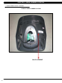
CHAPTER 1: Serial Number Location
1.1 SERIAL NUMBER LOCATION
SERIAL Number LOCATION
1
Chapter 1: Serial Number Location
1.1 SERIAL NUMBER LOCATION - CONTINUED
console serial number location
SN # PLACEMENT
2
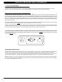
CHAPTER 2: Important Safety Instructions
2.1 READ THESE INSTRUCTIONS
This Suspension Elliptical is intended for commercial use. To ensure
your safety and protect the equipment, read all instructions before
operating the MATRIX Suspension Elliptical.
CAUTION! If you experience chest pains, nausea, dizziness, or
shortness of breath, stop exercising immediately and consult
your physician before continuing. When using an electrical product, basic precautions should always be
followed including the following:
CAUTION! Any changes or modifications to this equipment
could void the product warranty. • A
n appliance should never be left unattended when plugged
in. Unplug the unit from the outlet when not in use and before
putting on or taking off any parts.
• T
his product must be used for its intended purpose
described in this service manual. Do not use other
attachments that are not recommend by the manufacturer.
Attachments may cause injury.
• T
o prevent electrical shock, never drop or insert any object
into any opening. • D
o not remove the console covers. Service should only be
done by an authorized service technician.
• Do not carry this unit by it’s supply cord or use the cord as a handle. • C
lose supervision is necessary when the Suspension
Elliptical is used by or near children or disable persons.
• Do not use outdoors. • D
o not operate where aerosol (spray) products are being
used or when oxygen is being administered.
• T
o disconnect, turn all controls to the off position, then
remove the plug from the outlet.
• D
o not use the equipment in any way other than designed or
intended by the manufacturer. It is imperative that all Matrix
Fitness Systems equipment is used properly to avoid injury.
• Keep hands and feet clear of moving parts at all times to avoid injury.
• Unsupervised children must be kept away from this equip
ment.
• Do not wear loose clothing while on the equipment.
3
Chapter 2: important safety information
2.2 ELECTRICAL REQUIREMENTS
The Matrix Suspension Elliptical is designed to be self powered. NOTE: If an add on TV (using a bracket) is added to the unit, it must be
plugged in, or the TV will not operate correctly. If the Suspension Elliptical will be plugged in, follow the requirements below.
MATRIX DEDICATED CIRCUIT/ELECTRICAL REQUIREMENT INFO
All Matrix Suspension Ellipticals require the use of a 15 amp or 20 amp “dedicated circuit,” with a non-looped (isolated) neutral/ground, for the
power requirement. Quite simply this means that each outlet you plug Suspension Ellipticals into should not have anything else running on that
same circuit besides other Suspension Ellipticals (up to 3 per 15 amp circuit and 4 per 20 amp circuit). The easiest way to verify this is to locate
the main circuit breaker box, and turn off the breaker(s) one at a time. Once a breaker has been turned off, the only thing that should not have
power to it are the Suspension Ellipticals in question. No lamps, vending machines, fans, sound systems, or any other item should lose power
when you perform this test.
Non-looped (isolated) neutral/grounding means that each circuit must have an individual neutral/ground connection coming from it, and terminating
at an approved earth ground. You cannot “jumper” a single neutral/ground from one circuit to the next.
In addition to the dedicated circuit requirement, the proper gauge wire must be used from the circuit breaker box, to each outlet that will have the
maximum number of units running off of it. If the distance from the circuit breaker box, to each outlet, is 100 ft or less, then 12 gauge wire may be
used. For any distance greater than 100 ft from the circuit breaker box to the outlet, 10 gauge wire must be used.
For your safety and Suspension Elliptical performance, the ground on this circuit must be non-looped. Please refer to NEC article 210-21 and 210-23.
Your Suspension elliptical is provided with a power cord with a plug listed below and requires the listed outlet. Any alterations of this power cord
could void all warranties for this product. Multiple Suspension ellipticals can be powered on one dedicated circuit. (3 units per 15 Amp and 4 units
per 20 Amp dedicated circuit.)
GROUNDING INSTRUCTIONS:
The Matrix E5x-04 Suspension Elliptical must be grounded. If it should malfunction or break down, grounding provides a path of least resistance
for electric current to reduce the risk of electric shock. The Suspension Elliptical is equipped with a cord having an equipment grounding
conductor and a grounding plug. The plug must be plugged into an appropriate outlet that is properly installed and grounded in accordance with
all local codes and ordinances. If the user does not follow these grounding instructions, the user could void the Matrix limited warranty.
DANGER: Improper connection of the equipment grounding conductor can result in the risk of electric shock. Check with a qualified electrician
if the user is in doubt as to whether the product is properly grounded. Do not modify the plug provided with the product if it will not fit the outlet,
have a proper outlet installed by an electrician.
4
CHAPTER 3: Preventative Maintenance
3.1 RECOMMENDED CLEANING TIPS
In order to maximize life span, and minimize down time, all Matrix Fitness Equipment requires regularly
scheduled cleaning.
YOU WILL NEED:
-
Mild dish soap and water mixture in a spray bottle (10:1 water to soap ratio).
Lint free 100% cotton cleaning cloths or Micro fiber cleaning cloths.
Vacuum / Shop Vac with extendable hose and soft brush attachment.
Corrosion Block (available from Matrix - part # ZMS4001374).
DAILY:
1. Wipe down the unit after each use with a mild dish soap and water mixture. NOTE: Spray the soap / water mixture onto the cloth.
NEVER spray directly onto the equipment. We recommend that you do NOT allow customers to use spray bottles to clean the equipment. If
the cleaner is sprayed directly on the equipment or over spray is present, it may cause your equipment to rust and / or cause damage to console overlays.
WEEKLY:
1. With a clean dry 100% lint free cloth and water / soap mixture, wipe down the entire frame so it is free of dust, dirt, and sweat.
2. With a clean dry 100% lint free cloth and water / soap mixture, wipe down the entire console area including the hand grips and hand rails.
MONTHLY:
1. Vacuum under and around the Elliptical Trainer. If you need to move it, unplug the unit first.
2. Vacuum debris out of the foot pedals.
3. Apply Corrosion Block to the metal part of the iPod cable.
3.2 check for damaged parts
DO NOT use any equipment that is damaged or has worn or broken parts. Use only replacement parts supplied by Matrix Fitness Systems.
maintain labels and nameplates. Do not remove labels for any reason. They contain important information. If unreadable or missing,
contact Matrix Fitness Systems for a replacement. 1-866-693-4863, www.matrixfitness.com
maintain all equipment Preventative maintenance is the key to smooth operating equipment. Equipment needs to be inspected at regular
intervals. Defective components must be replaced immediately. Improperly working equipment must be kept out of use until it is repaired.
Ensure that any person(s) making adjustments or performing maintenance or repair of any kind is qualified to do so. Matrix Fitness Systems will
provide service and maintenance training at our corporate facility upon request or in the field if proper arrangements are made.
5
Chapter 3: Preventative Maintenance
3.3 CARE AND MAINTENANCE INSTRUCTION
In order to maximize life span, and minimize down time, all MATRIX equipment requires regular maintenance items performed on a scheduled
basis. This section contains detailed instructions on how to perform these items and the frequency of which they should be done. Some basic
tools and supplies will be necessary to perform these tasks which include (but may not be limited to):
* Metric Allen wrenches
* #2 Phillips head screwdriver
* Adjustable wrench
* Teflon based spray lubricant such as “Super Lube”, or other Matrix approved product
You may periodically see an addendum to this document, as the Matrix Technical Support Team identifies items that require specific attention, the
latest version will always be available on the Matrix website, www.matrixfitness.com
DAILY MAINTENANCE ITEMS
1. Attempt to wobble the unit back and forth, level if needed (see Section 10.4).
QUARTERLY MAINTENANCE ITEMS
1.
Check all connecting joint areas for tightness of bolt assemblies.
2.
Ensure that there is little, or no free play at all joint assemblies once bolts have been tightened. Installation of washer kits may be required
if free play does not come out from tightening bolts.
3.
Remove plastic covers, and lubricate the ball joint where the Link Arm and Handlebar join together. Use your finger to apply grease to the
ball bearing. Matrix recommends using Superlube brand grease with PTFE {Teflon} additive.
YEARLY MAINTENANCE ITEMS
1.
6
Remove the front round covers and check the belts for damage, alignment, and proper tension.
CHAPTER 4: Console Overlay and Workout Description
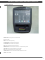
4.1 CONSOLE DESCRIPTION
WORKOUT KEYS: Simple program view and selection buttons.
GO: One touch Start.
ENTER: To confirm each program setting.
UP / DOWN LEVEL: Easy information and level selection.
UP / DOWN TIME: Easy information and time adjustment.
STOP: Ends workout and shows workout summary data.
NUMBER KEYPAD: Workout data input for workout setup. Level adjustment during workout.
COOL DOWN: Puts the Suspension Elliptical into Cool Down Mode.
FAN: Allows for fan speed selection (fan has 3 operating speeds).
TOGGLE DISPLAY: Allows user to select what information is displayed on the console.
Language: Select language.
7
Chapter 4: Console overlay and workout description
4.2 workout setup steps - MANUAL
GO - Press to immediately begin a workout. Workout, resistance
level, and time will automatically go to default settings. Pressing
GO will not prompt user for age, weight, or level settings.
ROLLING HILLS - The Rolling Hills program is a level based
1) Start pedaling and press the GO key to begin your workout. 2)
The display will read 3, 2, 1, Begin and then the program will start.
1) Start pedaling and press the ROLLING HILLS key. Then press
ENTER.
2) Select Level by using the UP or DOWN LEVEL keys and press
ENTER.
3) Select Time by using the UP or DOWN LEVEL keys and press
ENTER.
4) Select Weight by using the UP or DOWN LEVEL keys and press
ENTER.
5) Press Go, then the display will read 3, 2, 1, Begin and then the
program will start.
MANUAL - Manual allows the user to input more information
while defining their own workout. Calorie expenditure will be more
accurate when inputting information in Manual than by pressing GO.
1) Start pedaling, press the MANUAL key. Then press ENTER.
2) Select Level by using the UP or DOWN LEVEL keys and press
ENTER.
3) Select Time by using the UP or DOWN LEVEL keys and press
ENTER.
4) Select Weight by using the UP or DOWN LEVEL keys and press
ENTER.
5) Press GO, and then the display will read 3, 2, 1, Begin and then
the program will start.
4.3 workout setup steps - fat burn
FAT BURN - Fat burn is a level based program that is designed
to help users burn fat through various resistance level changes.
1) Start pedaling and press the FAT BURN key. Then press
ENTER.
2) Select Level by using the UP or DOWN LEVEL keys and press
ENTER.
3) Select Time by using the UP or DOWN LEVEL keys and press
ENTER.
4) Select Weight by using the UP or DOWN LEVEL keys and press
ENTER.
5) Press GO, then the display will read 3, 2, 1, Begin and then the
program will start.
8
4.4 workout setup steps - LEVEL BASED
program that automatically adjusts the resistance level to simulate
real terrain.
INTERVAL TRAINING - The Interval Training program is a
level based program that automatically adjusts the resistance of the
machine from low to high intensity settings at regular intervals.
1) Start pedaling and press the INTERVAL TRAINING key. Then
press ENTER.
2) Select Level by using the UP or DOWN LEVEL keys and press
ENTER.
3) Select Time by using the UP or DOWN LEVEL keys and press
ENTER.
4) Select Weight by using the UP or DOWN LEVEL keys and press
ENTER.
5) Press GO then the display will read 3, 2, 1, Begin and then the
program will start.
RANDOM - Random is a level based workout that randomly
adjusts the resistance of the machine.
1) Start pedaling and press the key next to RANDOM key. Then
press ENTER.
2) Select Level by using the UP or DOWN LEVEL keys and press
ENTER.
3) Select Time by using the UP or DOWN LEVEL keys and press
ENTER.
4) Select Weight by using the UP or DOWN LEVEL keys and press
ENTER.
5) Press GO, then the display will read 3, 2, 1, Begin and then the
program will start.
CHAPTER 4: Console Overlay and Workout Description
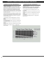
4.5 workout setup steps - cooper fitness test
FITNESS TEST -The Cooper Fitness Test measures cardiovascular fitness and proves an estimated sub-maximal VO2 result. It is based
on power output according to ACSM standards and was developed by the Cooper Institute© (www.cooperinstitute.org). User RPMs must
remain between 60-80 RPM during the test. The test will end when the user can no longer maintain this speed. Use of a heart rate strap is
optional but provides more data.
The test starts at a low intensity level and gradually increases in intensity (difficulty) every 2 minutes. As it increases, the user must maintain
60-80 RPM to advance to the next level. The test could take upwards of 30+ minutes for very fit individuals. Once the test ends a recovery
period (cool down) will begin and the user's results are calculated and displayed. Results are based on the number of stages completed.
Incline will not be adjustable during the test.
1)
2)
3)
4)
5)
6)
Start pedaling and press the FITNESS TEST key. Then press ENTER.
Select Age by using the UP or DOWN LEVEL keys and press ENTER.
Select Gender by using the UP or DOWN LEVEL keys and press ENTER.
Select Weight by using the UP or DOWN LEVEL keys and press ENTER.
Press GO, then the display will read 3, 2, 1, Begin and then the program will start.
Once the workout is complete, the display will read the results of the Fitness Test.
STAGES COMPLETED:
1
2
3
4
5
6
7
8
9+
Well Below Average
Well Below Average
Below Average
Below Average
Average
Average
Above Average
Above Average
Well Above Average
9
Chapter 4: Console overlay and workout description
4.6 workout setup steps - target heart rate
TARGET HEART RATE - The Matrix Suspension Elliptical
comes with standard digital contact heart rate sensors and are
POLAR telemetry compatible. The heart rate control workout mode
allows the user to program their desired heart rate zone, and the
elliptical will automatically adjust the level based upon the user's
heart rate. The heart rate zone is calculated using the following
equation: (220-Age)8%=target heart rate zone. The user must wear
a POLAR telemetric strap or continually hold onto the contact heart
rate grips for this workout.
Locate the metal sensors on the handlebars of the elliptical. Notice
that there are two separate pieces of metal on each grip. You must
be making contact with both pieces of each grip to get an accurate
heart rate reading. You can grab these sensors in any program to
view your current heart rate.
1) Start pedaling and press the HEART RATE key. Then press
ENTER.
2) Select Age by using the UP or DOWN LEVEL keys and press
SELECT.
3) Select Target HR Percentage by using the UP or DOWN LEVEL
keys and press SELECT.
4) Select Time by using the UP or DOWN LEVEL keys and press
SELECT.
5) Select Weight by using the UP or DOWN LEVEL keys and press
SELECT.
6) Press GO, then the display will read 3, 2, 1, Begin and the
program will start.
10
4.7 workout setup steps - CONSTANT watts
CONSTANT WATTS - Constant Watts is a unique program
that allows you to vary your cadence or RPM and the elliptical's
resistance level will adjust accordingly to your selected goal. The
quicker you pedal, the less resistance for the goal selected.
1) Start pedaling and press the CONSTANT WATTS key. Then
press ENTER.
2) Select Watts by using the UP or DOWN LEVEL keys and press
SELECT.
3) Select Time by using the UP or DOWN LEVEL keys and press
SELECT.
4) Select Weight by using the UP or DOWN LEVEL keys and
press SELECT.
5) Press GO, then the display will read 3, 2, 1, Begin and the
program will start.
CHAPTER 5: Manager Mode
5.1 manager mode OVERVIEW
The Manager's Custom Mode allows the club owner to customize the Suspension Elliptical for the club.
1) To enter Manager Mode, press and hold down the UP and DOWN LEVEL keys. Continue to hold down these two keys until the display
reads Manager Mode and hit ENTER (Figure A).
2) To scroll through the list of options in Manager Mode, use the UP and DOWN LEVEL keys. Each of the custom settings will show on the
display.
3) To select a custom setting, press the ENTER key when the desired setting is shown.
4) To change the value of the setting, use the UP and DOWN LEVEL keys.
5) To confirm and save the value of the setting, press the ENTER key.
6) To exit the setting without saving, press the BACK key.
7) Press and hold the STOP key for 3-5 seconds to return to normal operation.
figure a
11
Chapter 5: Manager Mode
5.2 manager mode Information
12
CUSTOM SETTING
DEFAULT
MINIMUM
MAXIMUM
Description
Maximum Time
60 min
5 min
99 min
Sets the total run time of any program.
Default Time
30 min
5 min
Maximum
Time
Setting
Workout time when GO is pressed or when no time is selected
during program set up.
Default Level
1
1
30
Starting resistance when GO is pressed or when no resistance is
selected during program set up.
Default Age
30
10
100
Starting age when GO is pressed or when no age is selected during
program set up.
Default User Weight
150 lbs /
68 kg
80 lbs / 36
kg
400 lbs /
182 kg
Weight used for program calorie expenditure calculations.
Accumulated Distance
N/A
0
99,999
Miles
Total distance for all programs.
Accumulated Time
N/A
0
999,999
hours
Total time for all programs displayed in hours.
Software Version
N/A
N/A
N/A
Current version of console software.
Speed / Distance Mode
Mile
Mile
Kilometer
Displays distance in miles or kilometers.
Out of Order
Off
On
Off
Locks the machine when out of order.
Gender
Male
Male
Female
Determines the gender of the user when not selected during program
set up.
Language
English
English
English
Sets the language for the console. Select between English, Spanish,
German, French, Italian, Portuguese, Finnish, Japanese, Swedish,
and Dutch.
Sound Mode
On
On
Off
Turns the chime on / off when a button is pressed.
CHAPTER 6: Engineering Mode
6.1 USING engineering mode
To enter Engineering Mode, hold the LEVEL UP and DOWN keys for 3-5 seconds until Manager Mode appears on the middle LED display.
Press the LEVEL UP or DOWN key to scroll to Engineering Mode. Press ENTER to go into Engineering Mode.
CODe
Default
Options
Description
Disable Errors
No
Yes or No
No - Shows A-C class error codes. Yes - Shows only C class error codes.
Speed Units
Mile
Mile or Kilometer
Set for Mile or Kilometer.
Machine Type
E5x-03
H5x, R5x, U5x,
E5x-02 or E5x-03
E5x-02 Frame - Old EP frame.
E5x-03 Frame - Suspension Elliptical (current)
Power Save Time
30 Seconds
30-60 Seconds
Power saving time for the self powered frame.
Pause Time
30 Seconds
15 - 120 Seconds
For non self powered frames only. Not used on this model.
Serial Number
N/A
N/A
Serial Number input is available for both the Console and Frame. Use the number
keys and UP / DOWN LEVEL keys to enter Engineering Mode. Due to the limited
LED characters, 2 layers are used to enter the serial number. First Layer:
- PPPPP V
- PPPPP is the product name.
- V is the version. If the version is A, just leave this blank.
Second Layer
- YY MM nnnnn.
- YY is the year (11, 12).
- MM is the month (e.g. 08, 09, 10).
- nnnnn is the actual serial number.
Use the UP / DOWN LEVEL keys to navigate the layers and the number keys to
input the serial number. The product name is dependent on the Machne Type
setting.
For example, the console is EP612 with ver. B with ver. A and the manufactured
date is 2011.08 with 98765. The frame is EP304 with ver. A and the manufactured
date is 2011.06 with 12345. Their serial numbers are:
Console SN: EP612B 1st layer, 110898765 2nd layer.
Frame SN: EP304 1st layer, 110612345 2nd layer.
Club ID
N/A
N/A
This sets the club ID for clubs using Asset Management.
ErP Mode (Sleep
Time)
Off
Off or On (1-30
Minutes)
If there is no use of the machine over a period of time, the console LEDs will turn
off (go into ErP mode).
Audio Source
Off
Off / TV / PC TV /
Remote TV
Manual setting that that sets which outside TV will have audio through the console
audio ports.
Volume Control
TV/ PCTV:
Output:13
1~ 32
REMOTE TV
Output:13
1~ 32
REMOTE TV
Input:15
1~ 15
Controls the default TV volume for entertainment wired through the C-Safe port.
a. Input Default (DF : 15 / Range : 1 ~ 15)
b. Max Default (DF : 32 / Range : 1 ~ 32)
c. Output Default (DF : 13 / Range : 1 ~ Max)
Remote TV support a / b / c item. TV and PCTV only support c item.
RF Radio
WIFI/RF Radio
AM System
To select AM output device by WIFI or RF Radio.
13
Chapter 7: Service Mode
7.1 USING SERVICE mode
To enter Service Mode, hold the LEVEL UP and DOWN keys for 3-5 seconds until Manager Mode appears on the middle LED display. Press
the LEVEL UP or DOWN key to scroll to Service Mode. Press ENTER to go into Service Mode.
14
CODe
Default
Options
Service 1
Display Test
Press the ENTER key repeatedly
to check each set of LEDs on the
display sequentially.
Service 2
Keypad Test
Press any key and the display
should show the corresponding
message.
Service 3
Distance / Time
Service 4
CSafe / RF Test
Press the ENTER key to test
CSAFE. Press the ENTER key
again to test the RF.
Service 5
Error Log
Shows the last 10 errors. Press
and LEVEL UP and DOWN for 3
seconds to clear the errors.
Service 6
Set Date / Time
Press the LEVEL keys to move
cursor, the number keys to set
date / time, and the ENTER key
to save.
Service 7
Export and Import Parameter
Export Parameter - Export all
parameters to a USB device.
Import Parameter 1 - Imports the
engineer parameters to a USB
device except serial number,
accumulated distance and time.
Import Parameter 2 - Imports the
engineer parameters to a USB
device.
Service 8
WiFi Function
Automatically detects the
available IP address and displays
it.
Distance:
Mile 0 - 99999
Kilometer 0 - 160898
Time:
0 - 999999
Description
Manually sets the Accumulated
Distance and Time.
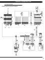
CHAPTER 8: Troubleshooting
8.1 Electrical DiagramS
HURES5x-C Electrical block diagram
15
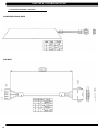
Chapter 8: Troubleshooting
8.1 electrical diagramS - CONTINUED
Pulse Sensor Wire
16
CHAPTER 8: Troubleshooting
8.1 electrical diagramS - Continued
E5x-F Electrical block diagram
Digital Communication Wire
Digital Communication Wire
17
CHAPTER 8: Troubleshooting
8.1 electrical diagramS - Continued
POWER RESISTANCE WIRE
ECB Wire
18
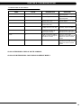
Chapter 8: Troubleshooting
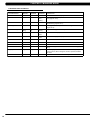
8.2 ERROR CODES ON THE CONSOLE
code
class
description
solution
0x02AB
c
Machine type error.
Set the correct machine type in
Engineering Mode.
0x02B4
c
Resistance type error.
Set the correct machine type in
Engineering Mode.
0x0201
a
Low voltage on the battery
(voltage under 11.2V).
Charge by running or by plugging
in the AC adapter.
0x0247
b
LCB failed (memory write error /
feedback ADC error).
Replace the LCB.
0x0248
b
Battery failure or disconnection
(Voltage under 8V or over 15V).
Check the wire connections at
the battery. Replace the battery.
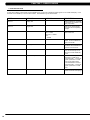
0x0441
b
When the UCB implements
a command, the LCB is not
receiving this command.
Check the machine type in
Engineering Mode. Check the
connections at the UCB and LCB.
0x04A0
c
Digital Communication Failure.
LCB has no return message for
the UCB for 3 seconds.
Check the console cable
connections at the UCB and LCB.
Replace the console or LCB as
needed.
0x04B0
C
UCB No Response.
Check the console cable
connections at the UCB and LCB.
Replace the console or LCB as
needed.
CLASS C errors will display on the console.
Class A or B errors will only display in Service Mode 5.
19
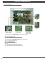
CHAPTER 8: Troubleshooting
8.3 LCB LED INDICATORS
====================== Firmware definition ========================
LED6: LCB status (blinking: OK)
LED7: Resistance Regulate Status (bright : Normal )
LED8: UCB/LCB Communication Status (blinking : OK )
====================== Hardware definition =======================
LED1: AC plug-in Status (bright : AC )
LED2: DC 5V Status (bright : OK)
LED3: AC plug-in Status (bright : AC )
LED4: DC 12V Status (bright : OK )
LED5: RPM
LED9: UCB Power Supply Status (bright: Power on)
LED10: Resistance PWM Status (bright: Resistance ON)
20
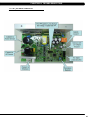
CHAPTER 8: Troubleshooting
8.4 LCB1_ErP wiring connection
21
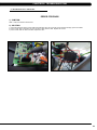
Chapter 8: Troubleshooting
8.5 troubleshooting - Error 04A0
ERROR CODE 04A0
1) SYMPTOM:
04A0 – PCB communication disconnected.
2) SOLUTION:
1) Check the connection of the console cable at the UCB and LCB. Also check the console cable for damage, replace as needed.
2) If the console cable connections are good, the issue is likely with the UCB. Replace the console.
3) If the console does not resolve the issue, replace the LCB.
Figure A
22
Figure B
CHAPTER 8: Troubleshooting
8.6 troubleshooting - Error 04b0
ERROR CODE 04B0
1) SYMPTOM:
04B0 – LCB communication disconnected.
2) SOLUTION:
1) Check the connection of the console cable at the UCB and LCB. Also check the console cable for damage, replace as needed.
2) If the console cable connections are good, the issue is likely with the UCB. Replace the console.
3) If the console does not resolve the issue, replace the LCB.
Figure A
Figure B
23
Chapter 8: Troubleshooting
8.7 troubleshooting - Error 0248
ERROR CODE 0248
1) SYMPTOM:
0248 –Battery disconnection or fail. (When the power is on, LCB battery voltage is less than 6 VAC)
2) SOLUTION:
1) Check the battery wire connection between the battery and LCB (Figure A).
2) Check the battery voltage (Figure B), if it is less than 6 VAC, replace the battery.
3) If the battery voltage is more than 6 VAC, replace the LCB.
Figure A
24
Figure B
Chapter 8: Troubleshooting
8.8 troubleshooting - Error 02B4
ERROR CODE 02B4
1) SYMPTOM:
02B4 – Resistance type error.
2) SOLUTION:
1) Check if the machine has the correct resistance system (resistor or ECB) (Figures A & B).
2) Check if the console is matched with the correct frame, and that the Machine Type is set correctly in Engineering Mode.
3) Replace the LCB.
4)..Replace the console. .
Resistor use on HUREA5x frame
Figure A
ECB use on SC5x frame and EP84 (ECB system E5x).
Figure B
25
Chapter 8: Troubleshooting
8.9 troubleshooting - Error 02AB
ERROR CODE 02AB
1) SYMPTOM:
02AB –Machine type error.
2) SOLUTION:
1) Check if the console machine type is matched with the correct frame in Engineering Mode.
Remarks: There are two types of E5x-F as below, each with different machine type in setting.
Machine type is E5x-02
Figure A
26
Machine type is E5x-03
Figure B
Chapter 8: Troubleshooting
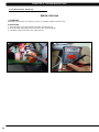
8.10 troubleshooting - Error 01AC
ERROR CODE 01AC
1) SYMPTOM:
01AC - Resistance over current.
2) SOLUTION:
1) Check the resistance coming out of the resistor (Figure A).
--If the resistance value is under 8 ohms, replace the power resistor.
--If the resistance value is over 8 ohms, replace the LCB.
Figure A
27
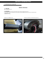
Chapter 8: Troubleshooting
8.11 troubleshooting - NO RESISTANCE ISSUE
NO RESISTANCE TROUBLESHOOTING
1) SYMPTOM:
No resistance
2) SOLUTION:
1) Check the power resistance wire connection between the power resistor and LCB (Figure A).
2) Check the resistance coming out of the resistor (Figure A).
--If the resistance value is under 8 ohms, replace the power resistor.
--If the resistance value is over 8 ohms, replace the LCB.
Figure A
28
Figure B
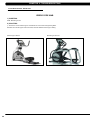
CHAPTER 8: Troubleshooting
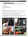
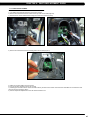
8.12 troubleshooting - heart rate issues
heart rate function does not work or is reading incorrectly
possible causes:
1)
2)
3)
4)
The
The
The
The
HR grips are not hooked up correctly.
HR grip wiring is damaged.
console or HR board is not properly grounded.
console, HR board, or wiring between are bad.
SOLUTION:
1) Perform a DC Voltage test on the HR grips.
a. With one prong of a multi meter on each of the plates on one side of the HR grip set (Figure A), a voltage reading of between .5 and 2.0
should be seen. If the reading is correct, the issue is not with the HR grips or grip wiring.
b. If the reading is not correct, remove the screws holding the halves of the HR grip together and check the connection of the wiring to the
grips (Figure B).
2) Remove the console from the unit and verify continuity of the HR grip wiring. With a multi meter set for ohms, place one prong on the HR grip
wiring coming up the console mast (Figure C), and the other on the appropriate plate (match red with red and white with white).
a. An ohm reading of less than 1 should be received. If it is higher, replace the HR grip wiring.
3) Perform a continuity check on the console (See Service Bulletin - Continuity Test on Matrix Elliptical Trainers).
a. Once the console continuity is confirmed, perform a continuity check on the HR board ground wire. With a multi meter set for ohms, place
one prong on the HR board ground wire (Figure D), and the other on the console ground wire. An ohm reading of less than 1 should be received.
If it is higher, replace the HR board.
4) If all the troubleshooting listed above has been performed, and the unit still has HR issues, replace the HR board.
a. If the HR board does not resolve the issue, replace the console.
figure a
figure B
figure C
figure D
29
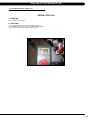
Chapter 8: Troubleshooting
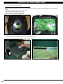
8.13 troubleshooting - No power to the console
Power switch is on, but the console has no display
possible causes:
1) The unit is not getting power from the outlet.
2) The LCB is not getting power from the power receptacle.
3 & 4) The LCB LEDs are lit, but there is no power to the console.
SOLUTION:
1) Verify power at the outlet. If the outlet is not outputting 120VAC, check the fitness room power.
2) Remove the front disk and check to see if LED9 is lit on the LCB (Figure A).
a. If it is not lit, verify power at the outlet. if the outlet is not outputting 120V power, check the fitness room power.
b. If LED9 is still not lit, check the incoming AC power to the LCB. If the incoming power is not correct, replace the power cord.
c. Replace the LCB if all power components are OK and there are AC volts to the LCB.
3 & 4)
a.
b.
cable.
c.
Remove the front disk and check to see if LED9 is lit on the LCB.
If LED9 is lit, check the connection of the console cable.
If the console cable is connected properly, LED2 on the control board should be lit (Figure B). If it is not lit, check voltage on the console
Measure voltage across pins 1 and 3 of the cable, it should show around 12V. Replace the console cable if this reading is off.
If LED2 on the control board is lit, but there is still no power to the console, replace the console.
figure a
30
figure B
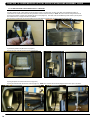
Chapter 8: Troubleshooting
8.14 troubleshooting - keypad issues
all or some of the function keys do not respond
possible causes:
1) The keypad connection ribbon cable has not been plugged in correctly.
2) The keypad is damaged.
3) The UCB is damaged.
SOLUTION:
1) Perform a keypad test in Service Mode:
a. Press and hold both the UP and DOWN LEVEL keys until Manager Mode appears on the display.
b. Use the UP and DOWN LEVEL keys to scroll to Service Mode 2 and press ENTER.
c. Test the affected keypad. If the keypad works in the keypad test it may not be a functioning key in the program used for testing it.
2) Check the connections of the keypad at the UCB.
a. Remove the console from the console mast.
b. Remove the 6 screws holding the back of the console to the front (Figure A).
c. Inspect the keypad ribbon cable connection at the UCB (Figure B).
d. Even if the keypad ribbon cable appears to be connected correctly, unplug and re-seat the cable.
3) Replace the affected keypad.
4) Replace the console.
figure a
figure b
31
CHAPTER 9: Part Replacement GUIDE
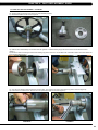
9.1 FRONT DISK REPLACEMENT
1) Remove the center cover by turning it counter clockwise (Figures A & B).
figure a
figure b
2) Remove the 3 screws holding the disk to the axle (Figure C).
3) Remove the disk (Figure D).
figure c
figure d
4) Reverse Steps 1-3 to install a new disk. NOTE: The 3 screws removed in Step 2 should be torqued to 25 N-m.
32
Chapter 9: Part Replacement guide
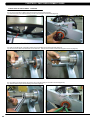
9.2 FRONT SHROUD REPLACEMENT
1) Remove the link arm and pedal arm plastic caps (Figures A & B).
FIGURE A
FIGURE B
2) Detach the dual action handlebar from the link arm (Figure C).
3) Secure the handlebar so that it is out of the way (Figure D).
FIGURE C
FIGURE D
4) Remove the front disks as outlined in Section 9.1.
5) Detach the pedal arm from the crank bearing assembly (Figure E).
6) Remove the 2 screws that hold the front top cover to the frame and remove the top cover (Figure F).
FIGURE E
FIGURE F
33
CHAPTER 9: Part Replacement GUIDE
9.2 FRONT SHROUD REPLACEMENT - CONTINUED
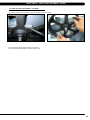
7) Pull out the rubber tray from the cup holder plastic (figure G).
8) Remove the 2 screws to disassemble the cup holder plastic and remove it from the unit (Figure H).
figure G
figure H
9) Remove the 2 screws to disassemble and remove the middle stabilizer sweat cover (Figures I & J).
figure I
figure J
10) Remove the 1 screw (exposed when the cup holder is removed) holding the orange slot cover to the frame and remove it (Figure K).
11) Remove all of the cables from the front shrouds (Figure L).
figure K
34
figure L
Chapter 9: Part Replacement guide
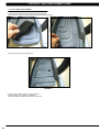
9.2 FRONT SHROUD REPLACEMENT - CONTINUED
12) Remove the 9 screws to detach the front shrouds from the frame (or each other) (Figure M).
13) Turn the crank to the slotted portion of the shroud (Figure N).
FIGURE M
FIGURE N
14) Remove the front shrouds for frame access (Figures O & P).
FIGURE O
FIGURE P
15) Reverse Steps 1-14 to install new shrouds. NOTE: The bolt / nut removed in Step 5 should be torqued to 70 N-m.
35
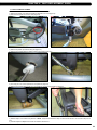
CHAPTER 9: Part Replacement GUIDE
9.3 lower control board replacement
1) Turn off the power and disconnect the cord from the machine.
2) Remove both front disks from the machine as outlined in Section 9.1.
3) Disconnect all wires from the LCB (Figure A).
figure a
4) Remove the 2 screws holding the LCB to the frame (Figure B).
figure b
5) Reverse Steps 1-4 to install a new LCB.
6) Test the Suspension Elliptical for function as outlined in Section 9.21.
36
Chapter 9: Part Replacement guide
9.4 GENERATOR REPLACEMENT
1)
2)
3)
4)
5)
Turn off power and disconnect the cord from the machine.
R
emove the front disks as outlined in Section 9.1.
Remove the front shrouds as outlined in Section 9.2.
Cut the cable tie holding the cable to the frame (Figure A).
Unplug the power cable connector of the generator (Figure B).
figure a
figure b
6) Loosen the nut holding the generator to the frame (Figure C).
7) Remove the three screws from the generator bracket (Figure D).
figure c
figure D
37
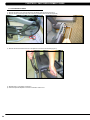
CHAPTER 9: Part Replacement GUIDE
9.4 GENERATOR REPLACEMENT – CONTINUED
8) Remove the nut from the other side of the generator bracket (Figure E).
9) Loosen and remove the generator belt (Figure F).
figure e
figure f
10) Remove the generator from the frame.
11) Reverse Steps 1-10 to install a new generator. Re-install the belts as outlined in Section 9.5. NOTE: The 3 screws removed in Step 7
should be torqued to 8 N-m and the nut from Step 8 to 40 N-m.
12) Test the Suspension Elliptical for function as outlined in Section 9.21.
38
Chapter 9: Part Replacement guide
9.5 GENERATOR BELT REPLACEMENT
1)
2)
3)
4)
5)
Turn off the power and disconnect the cord from the machine.
Remove the front disks from the machine as outlined in Section 9.1.
Remove the front shrouds as outlined in Section 9.2.
Remove the generator as outlined in Section 9.4.
To install a new belt, first put the belt installation tool on the pulley (Figure A).
figure A
6) Put the new belt on the installation tool (Figure B).
7) Turn the pulley until the belt is installed. Rotate the pulley at least 3 full rotations to insure that the belt is centered.
figure B
8) Reverse Steps 1-4 to re-assemble the unit.
9) Test the Suspension Elliptical for function as outlined in Section 9.21. .
39
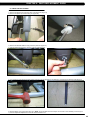
CHAPTER 9: Part Replacement GUIDE
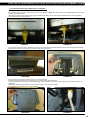
9.6 Drive BELT REPLACEMENT
1) Turn off the power and disconnect the cord from the machine.
2) Remove the front disks from the machine as outlined in Section 9.1.
3) Loosen the belt tension bolt on the left side of the tension pulley and rotate the pulley counter-clockwise until there is enough slack in the
belt to remove it (Figures A & B).
figure a
figure b
4) Install the replacement belt and reverse necessary steps to secure the assembly until the belt is tight. NOTE: Tighten the drive belt to 180
lbs for a new belt, 150 lbs for a used belt. The idler bolt should be torqued to 80 N-m.
5) Test the Suspension Elliptical for function as outlined in Section 9.21.
40
Chapter 9: Part Replacement guide
9.7 PULLEY AXLE SET REPLACEMENT
1)
2)
3)
4)
Turn off the power and disconnect the cord from the machine.
Remove both front disks from the machine as outlined in Section 9.1.
Loosen the belt tension bolt on the right side until there is enough slack to remove the drive belt (Figure A).
On the right side of the frame, remove the retaining clip that holds the pulley axle bearing into the frame (Figure B).
figure a
figure b
5) On the left side of the frame, remove the retaining ring that holds the pulley axle bearing into the frame (Figure C).
6) Remove the pulley axle set assembly from the frame. Clean any debris from the hole in the frame (Figure D).
figure c
figure d
7) Reverse Steps 1-6 to install a new pulley axle set. Rotate the pulley to make sure that the motion is smooth and that there is no wobbling to
one side. Re-install the belts as outlined in Sections 9.5 and 9.6.
8) Test the Suspension Elliptical for function as outlined in Section 9.21.
41
CHAPTER 9: Part Replacement GUIDE
9.8 DRIVE AXLE SET REPLACEMENT
NOTE: A Matrix special tool is needed to correctly replace a drive axle. Order part # 0000094817 from Matrix CTS at 866-693-4863 ext 3. 1) Turn off the power and disconnect the cord from the machine.
2) Remove the front disks from the machine as outlined in Section 9.1.
3) Remove both belts as outlined in Sections 9.5 & 9.6.
4) On the left side of the frame, remove the retainer clip that holds the drive axle bearings in the frame (Figure A).
5) Install an M10 screw into the drive axle (Figure B).
figure a
figure b
6) Turn the screw until the head is close to the drive axle (Figure C).
7) Use a hammer to hit the screw until the drive axle assembly is loose in the frame, and remove it (Figure D).
figure c
figure D
8) Install the tool into the hole in the frame (Figure E).
9) Use a rubber mallet to hit the end of the tool until the bearing can be removed from the frame (Figure F).
figure E
42
figure F
Chapter 9: Part Replacement guide
9.8 DRIVE AXLE SET REPLACEMENT - CONTINUED
10) The drive axle should have come with an iron plate installed (Figure G).
11) Assemble the Matrix tool as shown in Figure H.
figure G
figure H
12) Slide the drive axle assembly into the frame from the right side. Install the bearing cap portion of the tool into the left side of the frame
(Figure I).
13) Mount the other tool from Figure H behind the bearing cap portion of the tool. Use the M10 x 65L screw with a washer and a nut to attach the
tool to the drive axle (Figure J).
figure I
figure J
14) Turn the screw at least 4 full revolutions into the drive axle. Then turn the nut until it is close to the cup portion of the tool (Figure K).
15) Use a wrench to hold the screw, then turn the nut to pull the drive axle into the frame (Figure L).
figure K
figure L
43
CHAPTER 9: Part Replacement GUIDE
9.8 DRIVE AXLE SET REPLACEMENT - CONTINUED
16) Turn the nut until the iron plate is close to the frame on the right side (Figure M).
17) Remove the tools, then insert the bearing into the hole in the frame on the left side (Figure N).
figure M
figure N
18) Again use the M10 x 65L screw with a washer and a nut to attach the tool to the drive axle (Figure O).
19) Turn the screw at least 4 full revolutions into the drive axle. Then turn the nut until it is close to the cup portion of the tool (Figure P).
figure O
figure P
20) Use a wrench to hold the screw, then turn the nut to push the bearing into the hole in the frame (Figure Q).
21) Insert the retainer clip to hold the bearing in the frame (Figure R).
figure Q
44
figure R
Chapter 9: Part Replacement guide
9.8 DRIVE AXLE SET REPLACEMENT - CONTINUED
22) Use a screwdriver to remove the iron plate from the drive axle (Figures S & T).
figure S
figure T
23) Re-install the belts as outlined in Sections 9.5 and 9.6.
24) Test the Suspension Elliptical as outlined in Section 9.21.
45
CHAPTER 9: Part Replacement GUIDE
9.9 CRANK REPLACEMENT
1) Turn off the power and disconnect the cord from the machine.
2) Remove the front disks from the machine as outlined in Section 9.1.
3) Remove the screw from the crank (Figure A).
4) Insert an M10 screw (should be at least 40 long) into the crank hole. Then turn the screw until the crank can be separated from the axle
(Figure B).
figure A
figure B
5) Install the replacement crank. There should be a 4mm gap between the end of the drive axle shaft and the crank (Figure C).
figure C
6) Install the crank screw. NOTE: This screw should be torqued to 80 N-m.
7) Reverse Steps 1-2 to re-assemble the unit.
46
Chapter 9: Part Replacement guide
9.10 CONSOLE REPLACEMENT
1) Turn off the power and disconnect the cord from the machine.
2) R
emove the 5 screws that hold the console to the top of the console mast (Figure A).
3) Disconnect the console cable and other wiring and remove the console (Figure B).
figure a
figure b
4) Remove the 5 screws that hold the mounting plate to the console (Figure C).
figure C
5) Attach the mounting plate to the new console.
6) Connect the wire connections to the new console.
7) Carefully push the wires into the console and mast until they are clear of the console / mast connection and attach the console to the mast
using the 5 screws removed in Step 2.
8) Test the Suspension Elliptical for function as outlined in Section 9.21.
47
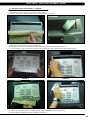
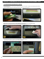
CHAPTER 9: Part Replacement GUIDE
9.11 OVERLAY & KEYPAD REPLACEMENT
NOTE: The instructions below are for console overlays / keypads replacement, but the procedure is the same regardless of where the overlay /
keypad is.
1) Turn off power and disconnect the cord from the machine.
2) Remove the console as outlined in Section 9.10.
3) Remove the back cover of the console (Figure A).
4) Unplug and remove the faulty overlay (Figure B).
figure a
figure b
5) Clean the console area with alcohol to remove any left over adhesive (Figure C).
6) Remove the protective film over the display window of the overlay (Figure D).
figure c
48
figure d
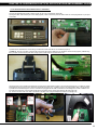
Chapter 9: Part Replacement guide
9.11 KEYPAD & OVERLAY REPLACEMENT - CONTINUED
7) Peel part of the protective film from the back of the overlay (Figure E).
8) Push the overlay ribbon cable through the hole in the console and plug it in (Figure F).
figure e
figure f
9) Match the overlay to the cutout on the console (Figure G).
10) Press down on the corners of the overlay to keep it in place, then remove the protective film (Figure H & I).
11) Once the overlay is in the correct position, press down on the overlay with a cloth to adhere it to the console plastic (Figure J).
figure g
figure i
figure h
figure j
12) Use the same procedure to replace any additional faulty overlays. NOTE: Overlays can not be reused.
13) Test the Suspension Elliptical for function as outlined in Section 9.21.
49
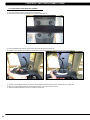
CHAPTER 9: Part Replacement GUIDE
9.12 CONSOLE MAST handlebar replacement
1) Turn off the power and disconnect the cord from the machine.
2) Remove the 4 bolts that hold the handlebar to the console mast (Figure A).
figure a
3) Pull the handlebar away from the console mast to expose the HR grip wiring (Figure B).
4) Carefully remove the wires from inside the console mast until the connectors on the ends come free and disconnect (Figure C).
figure B
figure C
5) To install a new handlebar assembly, connect the new handlebar and carefully push the heart rate wires into the console mast.
6) Attach the new handlebar assembly to the console mast using the 4 screws removed in Step 3.
7) Test the Suspension Elliptical for function as outlined in Section 9.21.
50
Chapter 9: Part Replacement guide
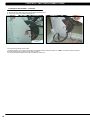
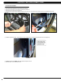
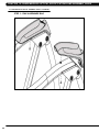
9.13 dual action handlebar replacement
1) Remove the plastic cover where the dual action handlebar meets the link arm (Figure A).
2) Remove the bolt and bushings where the dual action handlebar and the link arm meet (Figure B).
figure a
figure b
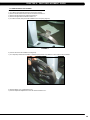
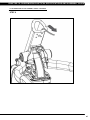
3) Remove the two bolts that hold on the pivot cap and remove the cap (Figure C).
4) Unplug and separate the heart rate connector exposed once the pivot cap is removed. Then remove the 4 screws that hold the dual action
handlebar to the console mast (Figure D).
figure c
figure d
5) Reverse steps 1-4 to install a new dual action handlebar.
6) Test the Suspension Elliptical for function as outlined in Section 9.21.
51
CHAPTER 9: Part Replacement GUIDE
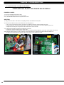
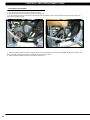
9.14 FOOT PEDALS REPLACEMENT
1) P
ull up on and remove the rubber portion of the pedal (Figure A).
2) Remove the 4 screws that hold the plastic pedal to the foot plate (Figure B).
figure a
figure b
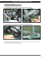
3) Remove the plastic foot pedal (Figure C).
figure c
4) Clean the foot plate to remove any rubber or debris.
5) Reverse Steps 1-4 to install a new foot pedal.
6) Test the Suspension Elliptical as outlined in Section 9.21.
52
Chapter 9: Part Replacement guide
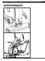
9.15 PEDAL ARM REPLACEMENT
1) Remove the plastic cover where the pedal arm attaches to the crank (Figure A).
2) Disconnect the pedal arm from the crank (Figure B).
figure a
figure b
3) Remove the plastic cap from the swing arm (Figure C).
4) Remove the bolt that holds the pedal and swing arms together (Figure D).
figure c
figure d
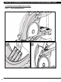
5) The swing arm can now be separate from the pedal arm (Figure E).
6) Remove the bolt that holds the link arm to the pedal arm and remove the pedal arm (Figure F).
figure E
figure F
7) Reverse Steps 1-5 to install a new pedal arm. NOTE: Torque the bolt removed in Step 4 to 80 N-m and the bolt / nut removed in Step 2 to 70
N-m.
8) Test the Suspension Elliptical for function as outlined in Section 9.21
53
CHAPTER 9: Part Replacement GUIDE
9.16 link arm replacement
1) Remove the plastic cover where the dual action handlebar meets the link arm (Figure A).
2) Remove the bolt and bushings where the dual action handlebar meets the link arm (Figure B).
figure a
figure b
3) Remove the bolt that holds the link arm to the pedal arm and remove the link arm (Figure C).
figure C
4) Reverse Steps 1-3 to install a new link arm.
5) Test the Suspension Elliptical for function as outlined in Section 9.21.
54
Chapter 9: Part Replacement guide
9.17 SWING ARM REPLACEMENT
1) Remove the bolt from the upper pivot joint on the swing arm (Figure A).
2) Remove the plastic cap from the swing arm (Figure B).
figure a
figure b
3) Remove the bolt that holds the swing arm to the pedal arm (Figure C).
4) Take the bolt removed in Step 1 and turn it into the shaft (Figure D).
figure C
figure D
5) Use a mallet to hit the head of the bolt until the swing arm can be separate from the pedal arm, and remove the pedal arm (Figures E & F).
figure E
figure F
6) Reverse Steps 1-5 to install a new swing arm. NOTE: Torque the bolts removed in Steps 1 & 3 to 80 N-m when installing a new swing arm.
7) Test the Suspension Elliptical for function as outlined in Section 9.21.
55
CHAPTER 9: Part Replacement GUIDE
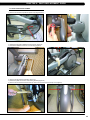
9.18 VERTICAL STABILIZER ARM REPLACEMENT
1) Remove the bolt that holds the vertical stabilizer arm to the frame (Figures A & B).
figure a
figure b
2) Remove the bolt from the upper pivot joint of the vertical stabilizer arm (Figure C).
3) Remove the vertical stabilizer arm (Figure D).
figure C
figure D
4) Reverse Steps 1-3 to install a vertical stabilizer arm. NOTE: Tighten the bolt removed in Step 2 to 80 N-m torque.
5) Test the Suspension Elliptical for function as outlined in Section 9.21.
56
Chapter 9: Part Replacement guide
9.19 INCLINE ARM COVER REPLACEMENT
1) Remove the screw that holds the plastic cover on the arm (Figures A & B).
figure a
figure B
2) Remove the incline arm cover (Figure C).
figure C
3) Reverse Steps 1-2 to install a new incline arm.
57
CHAPTER 9: Part Replacement GUIDE
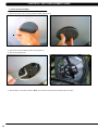
9.20 HANDLEBAR SERVICE
1) All items on the handlebar are removed using a Phillips screwdriver from the underside of the bar.
2) Once the screws are removed, lift the part carefully, then disconnect any wire connections to fully remove the part. This includes the
resistance buttons and heart rate grip plates (Figures A & B).
figure a
58
figure B
Chapter 9: Part Replacement guide
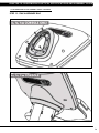
9.21 TESTING THE SUSPENSION ELLIPTICAL
Once the unit or replacement part is fully installed and assembled and
properly placed on the floor, use the following instructions to test
the machine:
1) Enter Engineering Mode and input the serial number of the console. Also set the Machine Type and verify that the Date and Time are
correct.
2) If the unit has an add on TV, perform a channel scan to tune the TV (see the TV Owner's Manual for procedure).
3) Without hitting start or entering any exercise modes, stand on the machine and hold the handlebars while initiating movement to simulate
exercising. While moving listen for any odd noises or squeaks.
4) After stopping movement, press the green GO key and begin using the machine.
5) Grasp the hand grips to check for proper heart rate response.
6) Press the LEVEL UP and DOWN keys both on the hand grips and on the console to make sure resistance is fully functional.
7) If everything functions properly, stop pedaling and the unit will reset to normal operation after 30 seconds.
59
CHAPTER 10: SUSPENSION ELLIPTICAL SPECIFICATIONS AND ASSEMBLY GUIDE
10.1 Suspension Elliptical specifications
MODEL NAME
MODEL TYPE
E5X ELLIPTICAL
FRAME PART #
E-3X/5X/7X-03-F
console part #
HURE-5x-04-C
Features
Stride Length
21” / 53.3 CM
Incline Range
N/A
Contact & Telemetric HR sensors
Yes
Cushioned Footpads
No
pedal spacing
2.5” / 6.4 CM
Handlebar design
Multi-position dual action and custom ergo-bend stationary
Thumb switch controls
yes
Resistance System
Technology
Generator
Power Requirements
Self Powered - Powered 100-125 V, 60 HZ or 216-250 V, 50 HZ
Minimum watts
21 Self-Powered
Minimum RPM
25 Powered & Self-Powered
Console
Display type
Dot-matrix LED
Display feedback
TIME ELAPSED, TIME REMAINING, TOTAL PROGRAM TIME, CLOCK, DISTANCE (KILOMETERS OR MILES), CALORIES,
SPEED, LEVEL, RPM, HEART RATE, METS, WATTS, STATIC PROFILE DISPLAY
User defined multi-language
display
Yes - English, German, French, Italian, Spanish, Dutch, Portuguese, Japanese, Swedish, Finnish
Resistance levels
25
Workouts
MANUAL, ROLLING HILLS, INTERVAL TRAINING, FAT BURN, RANDOM, FITNESS TEST, HEART RATE, CONSTANT WATtS
CSAFE, FitLinxx ready
Yes
Netpulse Ready
Yes
Fit Touch Technology™
No
On-the-fly program change
Yes
Integrated Vista Clear™ digital
ready television
No
FITCONNEXION™ ready
Yes
Wifi
Yes
ASSET MANAGEMENT COMPATIBLE
Yes
iPod Compatible
Yes - Charging Only
Nike + iPod Compatible
No
Personal Fan
Yes
Virtual Active™ compatible
No
Tech Specs
60
Overall dimensions
LxWxH
81x34x79"
1780x742x1740mm
Maximum user weight
400 lbs/182 kg
Weight
398 lbs/181.0Kg
Shipping weight
425 lbs/193.6Kg
Chapter 10: Suspension elliptical Specifications and assembly Guide
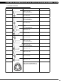
10.2 ASSEMBLY HARDWARE
quantity
sketch
description
package color
4
Socket head cap screw
(M10 x 1.5P x 25L)
10.9 Grade minimum
red (2 bags)
4
flat washer
(10.2 x 20 x 2.0t)
Red (2 bags)
1
Socket head cap screw
(M10 x 1.5P x 100L)
12.9 Grade Minimum
green
2
Flat washer
(10.2 x 20 x 2.0T)
Green
1
hex Nut
(M10)
10.9 grade minimum
green
5
screw
(M5 x 0.8P x 10L)
Yellow
2
Screw
(M5 x 0.8 x 12L)
Black (2 bags)
4
Spring Washer
(8.2 x 15.4 x 2.0t)
black (2 bags)
4
Socket head cap screw
(M8 x 1.25P x 20L)
10.9 grade minimum
Black (2 bags)
1
socket head cap screw
(m8 x 1.25P x 45L)
10.9 grade minimum
Blue (2 bags)
3
screw
(M5 x 0.8P x 16L)
blue (2 bags)
4
socket head cap screw
(M8 x 1.25P x 25L)
White
4
Spring Washer
(8.2 x 13.5 x 2.0T)
White
12
Screw
(M5 x 0.8P x 16L)
Pink
1
ADAPTOR PLATE
(ONLY USED ON PREMIUM AND la
CONSOLE INCLUDING E5x FRAME)
61
CHAPTER 10: SUSPENSION ELLIPTICAL SPECIFICATIONS AND ASSEMBLY GUIDE
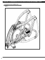
10.3 SUSPENSION ELLIPTICAL ASSEMBLY STEPS
step 1
62
CHAPTER 10: SUSPENSION ELLIPTICAL SPECIFICATIONS AND ASSEMBLY GUIDE
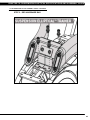
10.3 Suspension Elliptical assembly steps - continued
step 2 - RED HARDWARE BAG
63
CHAPTER 10: SUSPENSION ELLIPTICAL SPECIFICATIONS AND ASSEMBLY GUIDE
10.3 SUSPENSION ELLIPTICAL ASSEMBLY STEPS - CONTINUED
step 3 - Pink hardware bag
64
CHAPTER 10: SUSPENSION ELLIPTICAL SPECIFICATIONS AND ASSEMBLY GUIDE
10.3 Suspension Elliptical assembly steps - continued
step 4 - Green / Yellow HARDWARE BAG
Torque this bolt to 80 N-m.
65
CHAPTER 10: SUSPENSION ELLIPTICAL SPECIFICATIONS AND ASSEMBLY GUIDE
10.3 SUSPENSION ELLIPTICAL ASSEMBLY STEPS - CONTINUED
step 5 - Red hardware bag
66
CHAPTER 10: SUSPENSION ELLIPTICAL SPECIFICATIONS AND ASSEMBLY GUIDE
10.3 Suspension Elliptical assembly steps - continued
step 6
67
CHAPTER 10: SUSPENSION ELLIPTICAL SPECIFICATIONS AND ASSEMBLY GUIDE
10.3 SUSPENSION ELLIPTICAL ASSEMBLY STEPS - CONTINUED
step 7 - Blue / Black hardware bag
68
CHAPTER 10: SUSPENSION ELLIPTICAL SPECIFICATIONS AND ASSEMBLY GUIDE
10.3 Suspension Elliptical assembly steps - continued
step 8 - White hardware Bag
69
CHAPTER 10: SUSPENSION ELLIPTICAL SPECIFICATIONS AND ASSEMBLY GUIDE
10.3 SUSPENSION ELLIPTICAL ASSEMBLY STEPS - CONTINUED
step 9 - pink hardware bag
70
CHAPTER 10: SUSPENSION ELLIPTICAL SPECIFICATIONS AND ASSEMBLY GUIDE
10.3 Suspension Elliptical assembly steps - continued
step 10 - pink hardware Bag
71
CHAPTER 10: SUSPENSION ELLIPTICAL SPECIFICATIONS AND ASSEMBLY GUIDE
10.3 SUSPENSION ELLIPTICAL ASSEMBLY STEPS - CONTINUED
step 11 - pink hardware bag
72
CHAPTER 10: SUSPENSION ELLIPTICAL SPECIFICATIONS AND ASSEMBLY GUIDE
10.3 Suspension Elliptical assembly steps - continued
step 12 - pink hardware Bag
73
CHAPTER 10: SUSPENSION ELLIPTICAL SPECIFICATIONS AND ASSEMBLY GUIDE
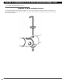
10.4 leveling the Suspension Elliptical
STABILIZING the MATRIX Suspension Elliptical
The Matrix Suspension Elliptical should be level for optimum use. Once you have placed your unit where you intend to use it, raise or lower
one or both of the adjustable levelers located on the bottom of the frame. Use a 6mm Allen wrench through the access hole at the rear hinge
joint on both sides (Figure A).
figure a
74
CHAPTER 10: SUSPENSION ELLIPTICAL SPECIFICATIONS AND ASSEMBLY GUIDE
10.5 TV BRAcket installation instructions
The Matrix Suspension Elliptical is capable of having a MYE Entertainment or Web Ready (PCTV) television installed using an integrated
bracket. Follow the instructions below to install the TV and TV bracket, and the instructions located in the TV owner's manual to program the TV.
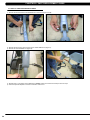
1) Remove the console from the unit as outlined in Section 9.1.
2) Remove the 6 screws holding the console front to the back and split the console (Figures A & B).
Figure A
Figure B
3) Remove the 2 screws holding on the blank headphone jack plastic to the console, and remove the plastic (Figures C & D).
Figure C
Figure D
4) Remove the wire in the console that goes from the UCB to the board on the console back (Figure E).
5) Install the new Y cable sent with the TV bracket kit to replace the wire removed in Step 4 (Figure F).
Figure E
Figure F
75
CHAPTER 10: SUSPENSION ELLIPTICAL SPECIFICATIONS AND ASSEMBLY GUIDE
10.5 TV Bracket Installation Instructions - Continued
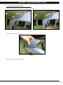
6) Run the white end from the Y cable through the headphone jack hole in the console plastic, and plug it into the headphone jack sent with the
TV bracket set (Figure G).
7) Mount the headphone jack into the console plastic using the 2 screws removed in Step 3 (Figure H).
Figure G
Figure H
NOTE: Steps 8 - 13 should only be done if installing a MYE TV (the PCTV does not use the entertainment overlay). 8) Remove the existing heart rate overlay from the lower portion of the console (Figure I).
9) Clean the console area with alcohol to remove any left over adhesive from the console plastic (Figure J).
10)
Figure I
Figure J
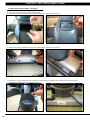
10) Peel off the protective film from the back of the entertainment keypad / overlay (Figure K).
11) Push the ribbon cable end through the hole in the console plastic (Figure L).
Figure K
76
Figure L
CHAPTER 10: SUSPENSION ELLIPTICAL SPECIFICATIONS AND ASSEMBLY GUIDE
10.5 TV BRAcket installation instructions - Continued
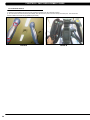
12) Press the entertainment keypad / overlay into the cut out in the console plastic (Figure M).
13) Plug the ribbon cable into the pins on the UCB (Figure N). Make sure that the pins and ribbon cable are correctly aligned with no pins open
on the UCB.
Figure M
Figure N
14) Mount the TV bracket to the console using 4 socket head screws sent with the TV bracket kit (Figure O).
15) MYE TV - Plug the 4 pin black connector side of the power wire into the UCB in the port marked TV Power for EP (Figure P). PCTV - Plug
the 4 pin black connector to the power wire coming up the console mast from the base of the unit.
Figure O
Figure P
16) Plug the side of the controller wire labeled To Console into the CSafe board mounted on the console back (Figure Q). The MYE TV should
be plugged into the TV port, the PCTV should be plugged into the PCTV port. If installing a PCTV, also change switch SW1 to the top location.
17) Route the net cable through the console. This wire is not plugged into the UCB, but should be routed through the console to hide the wire.
The 8 pin black connector on the net wire should stick out the bottom of the console along with the HR wiring (Figure R).
18) Connect one end of the coax cable to the board on the back cover using the adaptor sent with the TV kit (Figure S).
Figure Q
Figure R
Figure S
77
CHAPTER 10: SUSPENSION ELLIPTICAL SPECIFICATIONS AND ASSEMBLY GUIDE
10.5 TV Bracket Installation Instructions - Continued
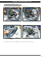
18) There should now be 4 wires sticking out the top of the console - TV power wire, net wire, coax cable, and controller wire (Figure T).
19) Re-attach the console back to the front using the bottom 6 screws removed in Step 2. NOTE: Be sure to route the wiring so that it is not
pinched by the bracket or plastic when installing the top 2 screws (Figure U). The small cover with the Matrix logo that makes up the top of the
rear console cover is no longer used with a TV bracket.
20) Mount the console back onto the unit making sure to make all the necessary wire connections including the coax cable.
Figure T
Figure U
21) Mount the plastic front plate to the TV (Figure V).
22) Plug the coax cable into the back of the TV (Figure W).
MYE TV
Figure V
PCTV
Figure W
23) Plug the power wire into the back of the TV (Figure X).
24) Plug the controller wire into the back of the TV (Figure Y). NOTE: The controller wire should be plugged into the PCTV port on the PCTV.
MYE TV
PCTV
Figure X
78
MYE TV
PCTV
Figure Y
CHAPTER 10: SUSPENSION ELLIPTICAL SPECIFICATIONS AND ASSEMBLY GUIDE
10.5 TV BRAcket installation instructions - Continued
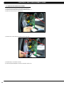
25) If installing a PCTV, plug the net wire into the back of the TV (Figure Z). NOTE: The net wire is not used if installing a MYE TV, and should
be hidden by the plastic covers.
26) If the PCTV will be using a wireless signal, plug the dongle into the back of the TV and mount the USB flash drive to the console plastic
using double sided foam tape (Figure AA).
Figure Z
Figure AA
27) Put the TV into place on the TV bracket being sure to tuck the tabs of the plate installed during Step 20 into the console plastic (Figure BB).
28) Mount the TV to the TV bracket using 4 screws sent with the TV (Figure CC).
Figure BB
Figure CC
29) Put the back cover onto the TV and secure with 4 screws (Figure DD).
30) Install the console back onto the unit making sure to connect the coax cable and net wire.
31) Plug a network wire (if using a PCTV not using wireless), power wire (PCTV only) and / or a coax cable to the port on the front of the unit
(Figure EE).
32) Enter into Engineering Mode and set the Audio Source setting for TV or PCTV as needed.
33) Program the TV as shown in the TV owner's manual.
Figure DD
Figure EE
79
Chapter 11: Software Upgrade procedure
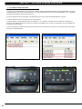
11.1 software upgrade procedure
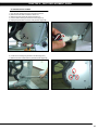
1. Create a file on the USB flash drive which will be used. The folders should be MATRIX\FW\UCB (create a folder called MATRIX, then a folder
in MATRIX called FW, then a folder in FW called UCB). Or you can put USB flash drive into the console and press ENTER, 9, 0, 0, 1, ENTER on
the keypad and the USB will create the folders (Figure A)
2. Copy the software files into the UCB folder on the USB flash drive (the access should read \MATRIX\FW\UCB - Figure B).
3. Insert the USB flash drive into the USB port on the console (Figure C).
4. With the display is in standard operation mode, press ENTER, 9, 0, 0, 1, ENTER on the keypad. Press the LEVEL UP or DOWN keys to
choose the correct software (if there are more than one version on the USB flash drive). Once the correct software is found, press ENTER and
the upgrade procedure will start.
5. If the console beeps and display shows 04A0 (Figure D), please remove the USB drive, turn off & turn on the machine again, and the display
will go back to standard operation.
80
figure a
figure b
figure c
figure d
notes
81
M ATr ix F i t n ess s y s t ems c o r p.
1610 Landmark D rive C ottage G rove wi 5 3 5 2 7 U S A
TO LL FREE 866. 693. 48 6 3 w w w. m a t r i x f i t n e s s . c o m FA X 6 0 8 . 8 3 9 . 1 7 1 7
REV. 01
KO