1
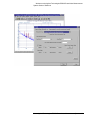
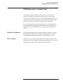
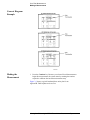
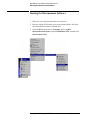
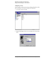
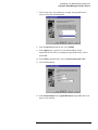
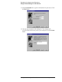
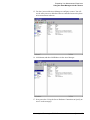
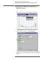
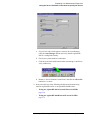
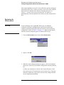
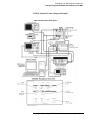
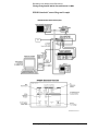
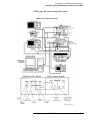
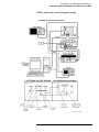
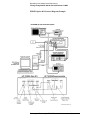
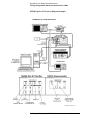
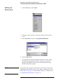
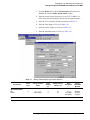
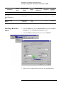
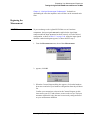
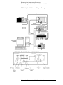
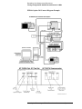
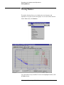
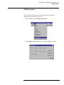
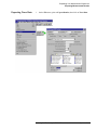
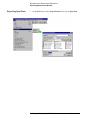
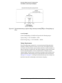
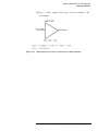
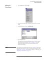
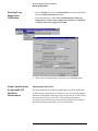
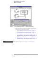
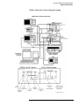
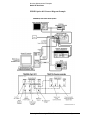
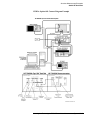
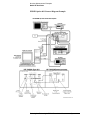
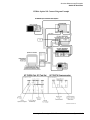
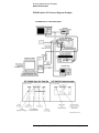
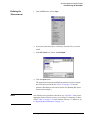
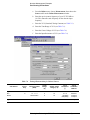
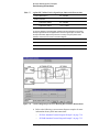
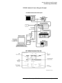
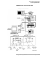
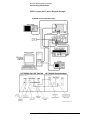
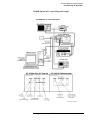
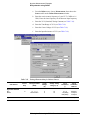
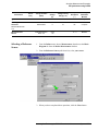
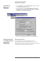
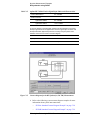
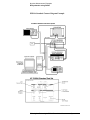
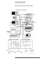
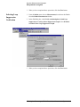
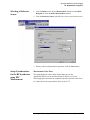
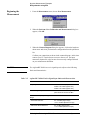
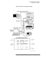
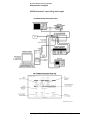
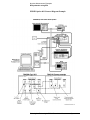
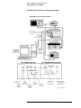
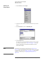
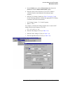
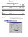
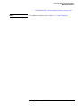
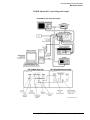
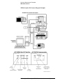
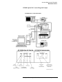
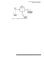
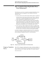
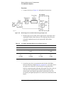
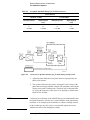
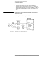
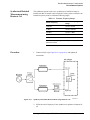
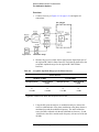
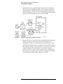
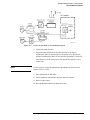
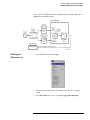
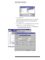
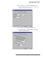
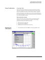
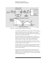
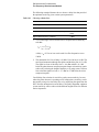
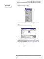
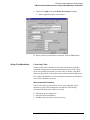
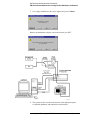
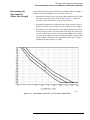
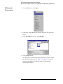
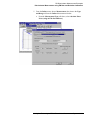
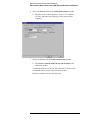
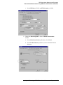
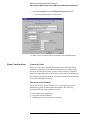
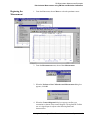
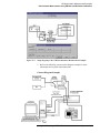
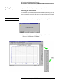
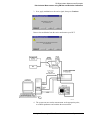
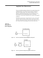
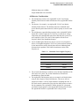
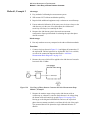
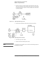
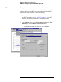
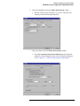
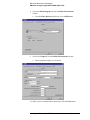
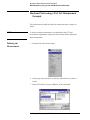
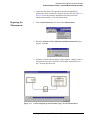
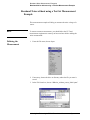
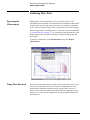
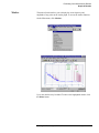
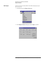
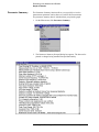
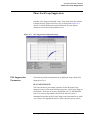
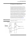
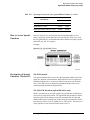
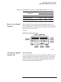
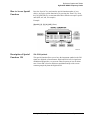
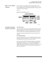
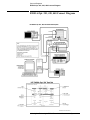
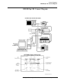
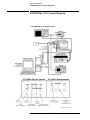
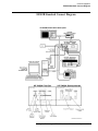
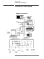
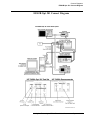
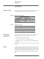
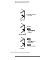
Expanding Your Measurement Experience
Testing the Agilent/HP 8663A Internal/External 10 MHz
If the output amplitude of your UUT is not sufficient to provide an adequate
measurement noise floor, it will be necessary to insert a low-noise amplifier
between the UUT and the test set. Refer to “Inserting an Device” in
Chapter 6, “Absolute Measurement Fundamentals” for details on
determining the effect the amplifiers noise will have on the measured noise
floor.
Beginning the
Measurement
CAUTION
To prevent damage to the Agilent/HP 70420A test set’s hardware
components, the input signal must not be applied to the signal input
connector until the input attenuator has been correctly set for the desired
configuration, as show in Table 5-3 on page 5-17. Apply the input signals
when the connection diagram appears, as shown below in step 3.
1. From the Measurement menu, choose New Measurement.
2. appears, click OK.
3. When the Connect Diagram dialog box appears, click on the hardware
down arrow and select your hardware configuration from the pull-down
list.
Confirm your connections as shown in the Connect Diagram. At this
time connect your UUT and reference sources to the test set. The input
attenuator (Option 001 only) has now been correctly configured based
on your measurement definition.
5-16 Agilent Technologies E5500 Phase Noise Measurement System