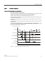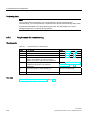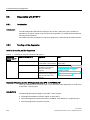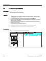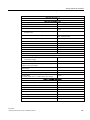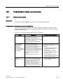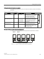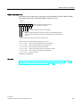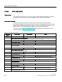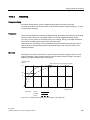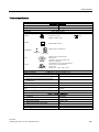
1
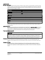
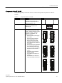
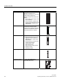
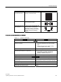
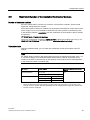
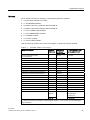
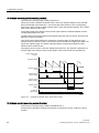
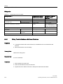
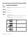
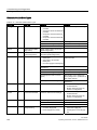
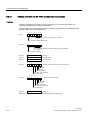
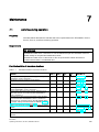
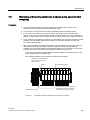
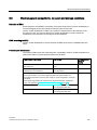
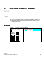
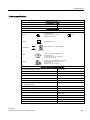
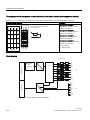
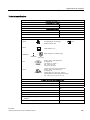
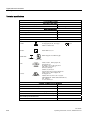
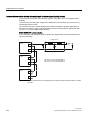
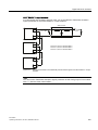
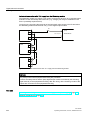
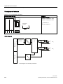
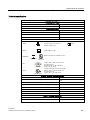
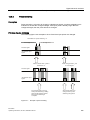
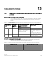
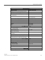
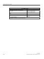
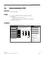
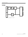
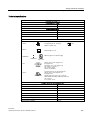
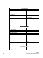
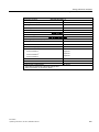
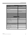
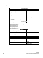
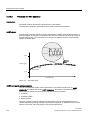
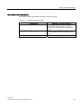
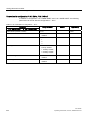
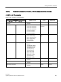
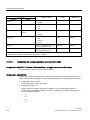
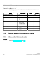
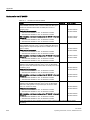
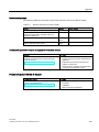
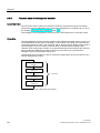
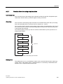
Configuration options 3.15 Time stamping Parameter Assignment With the parameter assignment you define which IM 152 user data will be monitored. For the time stamping these are digital inputs that are monitoring for signal changes. 3.15.2 Parameters Setting Description Time stamping disabled enabled Activate the time staming for the channels of the electronics module 8 DI NAMUR. Edge evaluation incoming event rising edge falling edge Determine the type of signal change that will be time-stamped. Time stamps accurate to 20 ms Introduction The time stamping of binary signal changes is supported in the PCS 7 system by all hardware and software components: from the ET 200iSP over the S7-400 right to the OS. Prerequisites ● Set a synchronization interval of 20 ms for the master and ET 200iSP. ● For time stamping, you require the 8 DI NAMUR electronics module with the "8DI NAMUR" configuration. Time stamping is not possible with any other configuration of the 8DI NAMUR electronics module. How time stamping works You can configure the monitoring of digital inputs for signal changes in HW Config. The following can be monitored: "Signal entering/leaving state" (as "rising or falling edge"). The IM 152 stamps these changed input signals with the current time of day and saves them as message lists. A message list is a data record with a maximum of 20 messages about timestamped signal changes. The IM 152 can store up to 15 data records. After a certain time and if messages exist or when a data record is full, the IM 152 triggers a hardware interrupt on the DP master (S7-400). The CPU then reads the data record and passes on the message lists to WinCC on an OS using the driver block FB90 "IM_DRV". ET 200iSP Operating Instructions, 01/2010, A5E00247483-04 63