Download McDATA Intrepid 6064 Director Service manual

Transcript
Intrepid® 6064 Director
Installation and Service Manual
P/N 620-000108-930
REV A
380 Interlocken Crescent Broomfield, CO 80021-3464
Corporate Headquarters: 800-545-5773
Sales E-mail: [email protected] Web: www.mcdata.com
Record of Revisions and Updates
ii
Revision
Date
Description
620-000108-100
2/2001
Initial release of the manual
620-000108-200
5/2001
Updates to describe Release 4.1 of the Enterprise Fabric Connectivity Manager application.
620-000108-300
6/2001
Additional updates to describe Release 4.1 of
the Enterprise Fabric Connectivity Manager
application.
620-000108-400
11/2001
Updates to describe Release 4.2 of the Enterprise Fabric Connectivity Manager application.
620-000108-500
5/2002
Updates to describe change from 1 to 2 gigabits/second and Release 6.0 of the Enterprise
Fabric Connectivity Manager application.
620-000108-600
9/2002
Updates to describe Release 6.1 of the Enterprise Fabric Connectivity Manager application.
620-000108-700
10/2002
Updates to describe Release 6.2 and 6.3 of the
Enterprise Fabric Connectivity Manager application.
620-000108-800
2/2003
Updates to describe Release 7.1 of the Enterprise Fabric Connectivity Manager application.
New cover and new format.
620-000108-801
6/2003
Updates to describe new firmware and software
download procedures from McDATA’s home
page.
620-000108-900
8/2003
Revision of the manual to describe the one unit
(1U) rack-mount server and Release 7.2 of the
Enterprise Fabric Connectivity Manager application.
Intrepid® 6064 Director Installation and Service Manual
620-000108-910
12/2003
Revision of the manual to describe Release
8.0/8.1 of the Enterprise Fabric Connectivity
Manager application. New style for safety
notices. Addition of translated safety notices.
620-000108-920
11/2004
Revision of the manual to describe Release 8.5
of the Enterprise Fabric Connectivity Manager
application, and the 10 Gbps (XPM) port card
and functionality.
620-000108-930
7/2005
Revision of the manual to describe Release 8.7
of the Enterprise Fabric Connectivity Manager
(EFCM) and EFCM Basic Edition application
and functionality.
Copyright © 2000-2005 McDATA Corporation. All rights reserved.
Printed July 2005
Twelfth Edition
No part of this publication may be reproduced or distributed in any form or by any means, or stored in a
database or retrieval system, without the prior written consent of McDATA Corporation.
The information contained in this document is subject to change without notice. McDATA Corporation
assumes no responsibility for any errors that may appear.
All computer software programs, including but not limited to microcode, described in this document are
furnished under a license, and may be used or copied only in accordance with the terms of such license.
McDATA either owns or has the right to license the computer software programs described in this document.
McDATA Corporation retains all rights, title and interest in the computer software programs.
McDATA Corporation makes no warranties, expressed or implied, by operation of law or otherwise, relating
to this document, the products or the computer software programs described herein. McDATA
CORPORATION DISCLAIMS ALL IMPLIED WARRANTIES OF MERCHANTIBILITY AND FITNESS FOR
A PARTICULAR PURPOSE. In no event shall McDATA Corporation be liable for (a) incidental, indirect,
special, or consequential damages or (b) any damages whatsoever resulting from the loss of use, data or
profits, arising out of this document, even if advised of the possibility of such damages.
Intrepid® 6064 Director Installation and Service Manual
iii
iv
Intrepid® 6064 Director Installation and Service Manual
Contents
Preface.......................................................................................................................... xvii
Chapter 1
General Information
Director Description .........................................................................1-1
Field-Replaceable Units ...................................................................1-4
Cable Management Assembly .................................................1-5
Front Bezel ..................................................................................1-5
CTP2 Card...................................................................................1-5
UPM Card ...................................................................................1-7
SFP Transceivers ........................................................................1-8
Power Supply .............................................................................1-9
RFI Shield....................................................................................1-9
Power Module Assembly .......................................................1-10
Fan Module...............................................................................1-10
SBAR Assembly .......................................................................1-10
Backplane ..................................................................................1-11
Error-Detection, Reporting, and Serviceability Features ..........1-11
Element Manager Status Indicators .............................................1-13
Tools and Test Equipment..............................................................1-14
Tools Supplied with the Director...........................................1-14
Tools Supplied by Service Personnel ....................................1-16
Director Management ....................................................................1-17
Chapter 2
Installation Tasks
Factory Defaults ................................................................................2-1
Installation Task Summary ..............................................................2-3
Task 1: Verify Installation Requirements .......................................2-5
Task 2: Unpack, Inspect, and Install the Ethernet Hub (Optional) .
Contents
v
Contents
2-6
Unpack and Inspect Ethernet Hub .........................................2-6
Desktop Installation ..................................................................2-7
Rack-Mount Installation ...........................................................2-8
Task 3: Unpack, Inspect, and Install the Director.........................2-9
Task 4: Configure Director at the EFCM Basic Edition Interface
(Optional).........................................................................................2-12
Configure Director Identification..........................................2-13
Configure Date and Time.......................................................2-14
Configure Parameters .............................................................2-15
Configure Fabric Parameters .................................................2-17
Configure Network Information...........................................2-18
Configure Basic Port Information .........................................2-20
Configure Port BB_Credit ......................................................2-21
Configure Port NPIV...............................................................2-21
Configure SNMP .....................................................................2-22
Enable CLI ................................................................................2-23
Enable or Disable Host Control.............................................2-24
Configure SSL Encryption......................................................2-25
Install PFE Keys (Optional)....................................................2-26
Configure Security...................................................................2-28
Configure Interswitch Links ..................................................2-30
Task 5: Configure Director Network Information (Optional) ..2-30
Task 6: Unpack, Inspect, and Install the Management Server..2-34
Task 7: Configure Server Password and Network Addresses..2-36
Configure Password................................................................2-36
Configure Private LAN Addresses .......................................2-37
Configure Public LAN Addresses (Optional) .....................2-38
Task 8: Configure Management Server Information .................2-38
Access the Management Server Desktop .............................2-38
Configure Management Server Names................................2-39
Configure Gateway and DNS Server Addresses ................2-40
Task 9: Configure Windows Operating System Users ..............2-42
Change Default Administrator Password ...........................2-42
Add a New User ......................................................................2-42
Change User Properties..........................................................2-43
Task 10: Set Management Server Date and Time .......................2-44
Task 11: Configure the Call-Home Feature (Optional)..............2-46
Task 12: Assign User Names and Passwords .............................2-47
Task 13: Configure the Director to the Management Application..
2-48
Task 14: Record or Verify Server Restore Information ..............2-49
Task 15: Verify Director-to-Server Communication...................2-50
vi
Intrepid® 6064 Director Installation and Service Manual
Contents
Task 16: Configure PFE Key (Optional) ...................................... 2-51
Task 17: Configure Management Server (Optional).................. 2-53
Task 18: Set Director Date and Time............................................ 2-54
Task 19: Configure the Element Manager Application............. 2-55
Configure Director Identification ......................................... 2-56
Configure Director Parameters ............................................. 2-56
Configure Fabric Parameters................................................. 2-58
Configure Ports ....................................................................... 2-60
Configure SNMP..................................................................... 2-61
Configure Threshold Alerts................................................... 2-62
Enable EFCM Basic Edition and Telnet Access .................. 2-65
Configure, Enable, and Test E-mail Notification ............... 2-65
Configure and Enable Ethernet Events................................ 2-67
Configure, Enable, and Test Call-Home Event Notification ....
2-67
Configure Security .................................................................. 2-68
Configure Interswitch Links.................................................. 2-69
Task 20: Back Up Configuration Data ......................................... 2-70
Task 21: Cable Fibre Channel Ports ............................................. 2-73
Task 22: Configure Zoning (Optional) ........................................ 2-73
Task 23: Connect Director to a Fabric Element (Optional) ....... 2-74
Task 24: Register with the McDATA Filecenter ......................... 2-75
Chapter 3
Maintenance Analysis Procedures (MAPS)
Factory Defaults ............................................................................... 3-1
Quick Start......................................................................................... 3-2
MAP 0000: Start MAP...................................................................... 3-8
MAP 0100: Power Distribution Analysis .................................... 3-13
MAP 0200: POST Failure Analysis .............................................. 3-16
MAP 0300: Loss of Server Communication................................ 3-20
MAP 0400: FRU Failure Analysis................................................. 3-30
MAP 0500: Port Failure or Link Incident Analysis.................... 3-34
MAP 0600: Fabric or ISL Problem Analysis ............................... 3-48
Chapter 4
Repair Information
Factory Defaults ........................................................................ 4-2
Procedural Notes....................................................................... 4-2
Obtaining Log Information............................................................. 4-3
SAN Management Logs ........................................................... 4-3
Element Manager Logs ............................................................ 4-5
EFCM Basic Edition Logs......................................................... 4-8
Contents
vii
Contents
Obtaining Port Diagnostic Information....................................... 4-11
Port LED Diagnostics..............................................................4-11
Element Manager Application Diagnostics .........................4-12
EFCM Basic Edition Diagnostics ...........................................4-17
Performing Loopback Tests...........................................................4-21
Internal Loopback Test (Element Manager Application) ..4-21
External Loopback Test (Element Manager Application) .4-23
Internal Loopback Test (EFCM Basic Edition) ....................4-24
External Loopback Test (EFCM Basic Edition) ...................4-26
Blocking and Unblocking Ports ....................................................4-27
Block or Unblock a Port or Port Card (Element Manager Application) ...................................................................................4-27
Block or Unblock a Port (EFCM Basic Edition)...................4-28
Swapping Ports ...............................................................................4-29
Performing Channel Wrap Tests (FICON) ..................................4-31
Collecting Maintenance Data........................................................4-32
Collecting Maintenance Data (Element Management Application)........................................................................................4-32
Collecting Maintenance Data (EFCM Basic Edition)..........4-33
Powering the Director On or Off ..................................................4-34
Power-On Procedure ..............................................................4-34
Power-Off Procedure ..............................................................4-35
Setting the Director Online or Offline..........................................4-36
Set Online or Offline (Element Manager Application) ......4-36
Set Online or Offline (EFCM Basic Edition) ........................4-37
IML, IPL, or Reset the Director .....................................................4-38
IML the Director (CTP Front Panel) .....................................4-38
IPL the Director (Element Manager Application) ..............4-39
Reset the Director (CTP Front Panel) ..................................4-39
Cleaning Fiber-Optic Components ..............................................4-40
Downloading Director Firmware and Software ........................4-41
Download Firmware and Software from Filecenter ..........4-42
Download Firmware and Software to Director (Element
Manger Application)...............................................................4-44
Download Firmware and Software to Director (EFCM Basic
Edition)......................................................................................4-46
Installing or Upgrading Software.................................................4-47
Managing Configuration Data......................................................4-50
Back Up Configuration (Element Manager Application)..4-50
Restore Configuration (Element Manager Application)....4-50
Reset Configuration Data (Element Manager Application) .....
4-51
Back Up Configuration (EFCM Basic Edition) ....................4-54
viii
Intrepid® 6064 Director Installation and Service Manual
Contents
Restore Configuration (EFCM Basic Edition) ..................... 4-54
Reset Configuration Data (EFCM Basic Edition) ............... 4-55
Chapter 5
Removal and Replacement Procedures (RRPs)
Factory Defaults ........................................................................ 5-1
Procedural Notes....................................................................... 5-2
Removing and Replacing FRUs ..................................................... 5-3
ESD Information........................................................................ 5-3
Concurrent FRUs....................................................................... 5-5
Nonconcurrent FRUs................................................................ 5-5
RRP: Cable Management Assembly.............................................. 5-6
RRP: CTP2 Card ............................................................................... 5-8
RRP: Port Module Card (UPM).................................................... 5-13
RRP: Optical Transceiver (SFP) .................................................... 5-18
RRP: Filler Blank (UPM)................................................................ 5-22
RRP: Power Supply........................................................................ 5-24
RRP: RFI Shield............................................................................... 5-28
RRP: SBAR Assembly .................................................................... 5-29
RRP: Fan Module ........................................................................... 5-33
RRP: Power Module Assembly .................................................... 5-37
RRP: Backplane............................................................................... 5-41
Chapter 6
Illustrated Parts Breakdown
Front-Accessible FRUs..................................................................... 6-2
Rear-Accessible FRUs ...................................................................... 6-4
Miscellaneous Parts ......................................................................... 6-6
Power Cords and Receptacles ........................................................ 6-8
Appendix A
Event Code Tables
System Events (000 through 199) ................................................. A-3
Power Supply Events (200 through 299) ................................... A-25
Fan Module Events (300 through 399) ...................................... A-29
CTP/CTP2 Card Events (400 through 499) .............................. A-37
Port Card (UPM) Events (500 through 599) .............................. A-50
SBAR Events (600 through 699) ................................................. A-62
Thermal Events (800 through 899) ............................................. A-66
Appendix B
Director Specifications
Physical Characteristics............................................................B-1
Shipping and Storage Environment .......................................B-2
Contents
ix
Contents
Operating Environment........................................................... B-2
Fabricenter Equipment Cabinet Service Clearances............ B-3
Appendix C
Management Server and Ethernet Hub
Management Server Description................................................... C-1
Management Server Specifications ........................................ C-2
Ethernet Hub Description .............................................................. C-2
Appendix D
Restore Management Server
Requirements ...................................................................................D-1
Restore Management Server Procedure ......................................D-2
Appendix E
Safety Notices (Multi-Lingual Translations)
Glossary ........................................................................................................................g-1
Index ................................................................................................................................i-1
x
Intrepid® 6064 Director Installation and Service Manual
Figures
1-1
1-2
1-3
1-4
1-5
1-6
1-7
1-8
1-9
1-10
Cabinet-Mounted Intrepid 6064 Directors and Management Server ... 1-3
Director FRUs (Front Access) ..................................................................... 1-4
Director FRUs (Rear Access) ....................................................................... 1-5
UPM Card LEDs and Connectors .............................................................. 1-8
Small Form-Factor Pluggable (SFP) transceiver ...................................... 1-9
Torque Tool and Hex Adapter ................................................................. 1-15
Door Key ...................................................................................................... 1-15
Loopback Plug ............................................................................................ 1-15
Fiber-Optic Protective Plug ....................................................................... 1-16
Null Modem Cable ..................................................................................... 1-16
2-1
2-2
2-3
2-4
2-5
2-6
2-7
2-8
2-9
2-10
2-11
2-12
2-13
2-14
2-15
2-16
2-17
2-18
Patch Cable and MDI Selector Configuration .......................................... 2-8
Mounting Bracket Installation (Ethernet Hub) ........................................ 2-8
AC Power Connections (Director) ........................................................... 2-11
Identification View ..................................................................................... 2-14
Date Time View .......................................................................................... 2-15
Parameters View ......................................................................................... 2-15
Fabric Parameters View ............................................................................. 2-17
Network View ............................................................................................. 2-19
Basic Information View ............................................................................. 2-21
SNMP View ................................................................................................. 2-22
CLI View ...................................................................................................... 2-24
OSMS View .................................................................................................. 2-24
SSL View ...................................................................................................... 2-26
Maintenance Feature Installation View .................................................. 2-28
Connection Description Dialog Box ........................................................ 2-32
1U Management Server Connections ...................................................... 2-35
Identification Changes Dialog Box .......................................................... 2-40
Internet Protocol (TCP/IP) Properties Dialog Box ................................ 2-41
Figures
xi
Figures
xii
2-19
2-20
2-21
2-22
2-23
2-24
2-25
2-26
2-27
2-28
2-29
2-30
2-31
2-32
2-33
2-34
2-35
2-36
2-37
Add New User Wizard ............................................................................... 2-43
Properties Dialog Box (General Tab) ........................................................ 2-44
Date/Time Properties Dialog Box (Time Zone Tab) .............................. 2-45
Date/Time Properties Dialog Box (Date & Time Tab) .......................... 2-46
Add User Dialog Box .................................................................................. 2-47
Address Properties Dialog Box (IP Address Page) ................................ 2-49
New Feature Key Dialog Box .................................................................... 2-53
Configure Date and Time Dialog Box ...................................................... 2-54
Configure Identification Dialog Box ........................................................ 2-56
Configure Switch Parameters Dialog Box ............................................... 2-57
Configure Fabric Parameters Dialog Box ................................................ 2-58
Configure Ports Dialog Box ....................................................................... 2-60
Configure SNMP Dialog Box .................................................................... 2-62
New Threshold Alert Dialog Box (Screen 1) ........................................... 2-63
New Threshold Alert Dialog Box (Screen 2) ........................................... 2-64
New Threshold Alert Dialog Box (Screen 3) ........................................... 2-65
Email Event Notification Setup Dialog Box ............................................ 2-66
InCD Icon (Unformatted CD) .................................................................... 2-71
McDATA Filecenter Home Page .............................................................. 2-76
3-1
3-2
3-3
Daisy-Chained Ethernet Hubs .................................................................. 3-24
UPM Card Diagram (OSI) .......................................................................... 3-44
UPM Card Diagram (FICON) ................................................................... 3-44
4-1
4-2
4-3
4-4
4-5
4-6
4-7
4-8
4-9
4-10
4-11
4-12
4-13
4-14
4-15
4-16
4-17
4-18
4-19
Port List View .............................................................................................. 4-13
Port Properties Dialog Box ........................................................................ 4-15
Port Technology Dialog Box ...................................................................... 4-17
Port List View .............................................................................................. 4-18
Port Diagnostics Dialog Box ...................................................................... 4-22
Diagnostics View ......................................................................................... 4-25
Basic Information View .............................................................................. 4-29
Swap Ports Dialog Box ............................................................................... 4-30
Save Data Collection Dialog Box .............................................................. 4-32
System Files View ....................................................................................... 4-33
Set Online State Dialog Box ....................................................................... 4-37
Switch View ................................................................................................. 4-37
Clean Fiber-Optic Components ................................................................ 4-41
McDATA Filecenter Home Page .............................................................. 4-42
Firmware Library Dialog Box .................................................................... 4-44
Firmware Upgrade View ........................................................................... 4-46
InstallShield Wizard Dialog Box ............................................................... 4-48
Backup and Restore Configuration Dialog Box ...................................... 4-50
Reset Configuration Dialog Box ................................................................ 4-51
Intrepid® 6064 Director Installation and Service Manual
Figures
4-20
4-21
4-22
4-23
Discover Setup Dialog Box ........................................................................
Address Properties Dialog Box ................................................................
Backup Configuration View .....................................................................
Restore Configuration View .....................................................................
4-52
4-53
4-54
4-55
5-1
5-2
5-3
5-4
5-5
5-6
5-7
5-8
5-9
5-10
5-11
5-12
5-13
5-14
5-15
5-16
5-17
5-18
ESD Grounding Point (Front) ..................................................................... 5-4
ESD Grounding Point (Rear) ...................................................................... 5-4
Cable Management Assembly Removal and Replacement .................... 5-7
CTP2 Card Removal and Replacement ..................................................... 5-9
UPM Card Removal and Replacement ................................................... 5-15
SFP Optical Transceiver Removal and Replacement ............................ 5-19
Filler Blank Removal and Replacement .................................................. 5-23
Power Supply Removal and Replacement ............................................. 5-25
RFI Shield Removal and Replacement .................................................... 5-28
SBAR Assembly Removal and Replacement .......................................... 5-30
Fan Module Removal and Replacement ................................................. 5-34
Power Module Assembly Removal and Replacement .......................... 5-38
Backplane Removal and Replacement .................................................... 5-43
Connection Description Dialog Box ........................................................ 5-46
Connect To Dialog Box .............................................................................. 5-46
COMn Dialog Box ...................................................................................... 5-47
HyperTerminal Dialog Box ....................................................................... 5-48
6-1
6-2
6-3
6-4
Front-Accessible FRUs .................................................................................
Rear-Accessible FRUs ..................................................................................
Miscellaneous Parts ......................................................................................
Power Cords and Receptacles ....................................................................
C-1
C-2
Management Server ..................................................................................... C-1
24-Port Ethernet Hub ................................................................................... C-3
D-1
D-2
D-3
D-4
D-5
Run Dialog Box ............................................................................................
VNC Authentication Screen .......................................................................
Welcome to Windows Dialog Box ............................................................
Log On to Windows Dialog Box ...............................................................
EFCM Log In or SANavigator Log In Log In Dialog Box ......................
Figures
6-2
6-4
6-6
6-8
D-4
D-5
D-5
D-6
D-6
xiii
Figures
xiv
Intrepid® 6064 Director Installation and Service Manual
Tables
1-1
Element Manager Alert Symbols, Messages, and Status ...................... 1-13
2-1
2-2
2-3
2-4
Factory-Set Defaults (Director) ................................................................... 2-1
Factory-Set Defaults (Management Server) .............................................. 2-2
Installation Task Summary ......................................................................... 2-3
Operational States and Symbols ............................................................... 2-51
3-1
3-2
3-3
3-4
3-5
3-6
3-7
3-8
3-9
3-10
3-11
3-12
3-13
3-14
3-15
3-16
Factory-Set Defaults ..................................................................................... 3-1
MAP Summary ............................................................................................. 3-2
Event Codes versus Maintenance Action ................................................. 3-2
MAP 100 Event Codes ............................................................................... 3-13
MAP 200 Event Codes ............................................................................... 3-16
MAP 200: Byte 0 FRU Codes ..................................................................... 3-16
MAP 300 Error Messages .......................................................................... 3-22
MAP 400: Event Codes .............................................................................. 3-30
MAP 500: Event Codes .............................................................................. 3-34
Link Incident Messages ............................................................................. 3-35
Invalid Attachment Reasons and Actions ............................................... 3-36
Inactive Port Reasons and Actions ........................................................... 3-41
MAP 600 Event Codes ............................................................................... 3-48
E_Port Segmentation Reasons and Actions ............................................ 3-50
Port Fence Codes and Actions .................................................................. 3-55
Fabric Merge Failure Reasons and Actions ............................................ 3-58
4-1
4-2
Factory-Set Defaults ..................................................................................... 4-2
Port Operational States .............................................................................. 4-11
5-1
5-2
Factory-Set Defaults ..................................................................................... 5-1
Concurrent FRUs .......................................................................................... 5-5
Tables
xv
Tables
xvi
5-3
Nonconcurrent FRUs .................................................................................... 5-5
6-1
6-2
6-3
6-4
Front-Accessible FRU Parts List ..................................................................
Rear-Accessible FRU Parts List ...................................................................
Miscellaneous Parts ......................................................................................
Power Cord and Receptacle List .................................................................
Intrepid® 6064 Director Installation and Service Manual
6-3
6-5
6-7
6-9
Preface
This publication is part of a documentation suite that supports the
McDATA® Intrepid® 6064 Director.
Who Should Use This
Manual
This publication is intended for installation and service
representatives experienced with the director, storage area network
(SAN) technology, and Fibre Channel technology.
Organization of This
Manual
This publication includes six chapters and four appendices organized
as follows:
Chapter 1, General Information. This chapter describes the director,
including field-replaceable units (FRUs), controls, connectors,
and indicators, and director specifications. The chapter also
describes the maintenance approach, director management
through the Enterprise Fabric Connectivity (EFC) Server, EFCM
Basic Edition interface, or a remote workstation, error detection
and reporting features, serviceability features, software
diagnostic features, and tools and test equipment.
Chapter 2, Installation Tasks. This chapter describes tasks to install,
configure, and verify operation of the director, optional Ethernet
hub, and management server.
Chapter 3, Maintenance Analysis Procedures (MAPS). This chapter
describes maintenance analysis procedures (MAPs) to fault
isolate a director problem to an individual FRU.
Chapter 4, Repair Information. This chapter describes
supplementary diagnostic and repair procedures for a failed
director. The chapter includes procedures to display and use log
information, perform port diagnostics, manage configuration
Intrepid® 6064 Director Installation and Service Manual
xvii
Preface
data, collect maintenance data, power-on, power-off, and reset
the director, set the director online or offline, block ports, manage
director firmware, clean fiber optics, and install or upgrade
management server software.
Chapter 5, Removal and Replacement Procedures (RRPs). This
chapter describes procedures to remove and replace director
FRUs.
Chapter 6, Illustrated Parts Breakdown. This chapter illustrates,
describes, and shows the location of director FRUs. In addition,
FRUs are cross-referenced to corresponding part numbers.
Appendix A, Event Code Tables This appendix provides an
explanation of event codes that appear at the Element Manager
application or EFCM Basic Edition interface. The event severity
and a recommended course of action in response to each event are
also provided.
Appendix B, Director Specifications. This appendix provides the
director specifications including its physical characteristics, and
storage, shipping, and operating environments.
Appendix C, Management Server and Ethernet Hub. This appendix
provides the management-server specifications and a description
of the ethernet hub.
Appendix D, Restore Management Server This appendix provides
the instructions to restore all required director applications to the
management server in case of a hard drive failure.
Appendix E, Safety Notices (Multi-Lingual Translations) This
appendix provides the translation of the safety notices in this
publication.
A Glossary defines terms, abbreviations, and acronyms used in the
manual. An Index is also provided.
xviii
Intrepid® 6064 Director Installation and Service Manual
Preface
Related Publications
Ordering Printed
Manuals
Other publications that provide additional information about the
director include:
•
McDATA Products in a SAN Environment Planning Manual
(620-000124).
•
McDATA Intrepid 6140 and 6064 Directors Element Manager User
Manual (620-000153).
•
McDATA Enterprise Fabric Connectivity Manager User Manual
(620-005001).
•
McDATA EFCM Basic Edition User Manual (620-000160).
•
McDATA SNMP Support Manual (620-000131).
•
McDATA E/OS Command Line Interface User Manual (620-000134).
•
McDATA Rack-Mount Kit, Intrepid 6064 Director in Fabricenter
(FC-512) Cabinet, Installation Instructions (958-000270).
•
McDATA EFCM Lite Installation Instructions (958-000171).
•
1U Server Rack-Mount Kit Installation Instructions (958-000310).
•
SANavigator User Guide (621-000013).
•
McDATA FC-512 Fabricenter Equipment Cabinet Installation and
Service Manual (620-000100).
To order a printed copy of this publication, contact your McDATA
representative or contact McDATA at the phone number or fax
number listed below.
Phone: (800) 545-5773 and select the option for information about
McDATA’s complete family of enterprise-to-edge SAN solutions.
Fax: (720) 558-4193
Where to Get Help
For technical support, contact the McDATA Solution Center. The
center provides a single point of contact, and is staffed 24 hours a day,
seven days a week, including holidays. Contact the center at the
phone number, fax number, or e-mail address listed below. Please
have the product serial number (printed on the service label attached
to the director) available.
Phone: (800) 752-4572 or (720) 566-3910
Fax: (720) 566-3851
E-mail: [email protected]
Intrepid® 6064 Director Installation and Service Manual
xix
Preface
For technical support for the SANavigator® application, contact the
SANavigator Solution Center at the phone number or e-mail address
listed below.
Phone: (877) 948-4448
E-mail: [email protected]
Forwarding
Publication
Comments
We welcome comments about this publication. Please send comments
to the McDATA Solution Center by telephone, fax, or e-mail. The
numbers and e-mail address are listed above. Please identify the
manual, page numbers, and details.
Trademarks
The following terms, indicated by a registered trademark symbol
(®) or trademark symbol (™) on first use in this publication, are
trademarks of McDATA Corporation or SANavigator, Inc. in the
United States or other countries or both:
Registered Trademarks
Trademarks
McDATA®
Sphereon™
Intrepid®
Fibre Channel Director™
Fabricenter®
SANavigator®HotCAT™
OPENready®
OPENconnectors™
EFCM Basic Edition®
EON™
SANtegrity®
All other trademarked terms, indicated by a registered trademark
symbol (®) or trademark symbol (™) on first use in this publication,
are trademarks of their respective owners in the United States or
other countries or both.
Laser Compliance
Statement
xx
Laser transceivers for the director are tested and certified in the
United States to conform to Title 21 of the Code of Federal
Regulations (CFR), Subchapter J, Parts 1040.10 and 1040.11 for Class 1
laser products. Elsewhere, the transceivers are tested and certified to
be compliant with International Electrotechnical Commission
IEC825-1 and European Norm EN60825-1 and EN60825-2 regulations
for Class 1 laser products. Class 1 laser products are not considered
hazardous. The transceivers are designed such that there is never
human access to laser radiation above a Class 1 level during normal
operation or prescribed maintenance conditions.
Intrepid® 6064 Director Installation and Service Manual
Preface
Federal
Communications
Commission (FCC)
Statement
The director generates, uses, and can radiate radio frequency energy,
and if not installed and used in accordance with the instructions
provided, may cause interference to radio communications. The
directors have been tested and found to comply with the limits for
Class A computing devices pursuant to Subpart J of Part 15 of the
FCC Rules, which are designed to provide reasonable protection
against such interference in a commercial environment. Operation of
this equipment in a residential area is likely to cause interference in
which case the user, at his or her own expense, will take whatever
measures are required to correct the interference. Any modifications
or changes made to the director without explicit approval from
McDATA, by means of a written endorsement or through published
literature, will invalidate the service contract and void the warranty
agreement with McDATA.
Chinese Class A
Telecommunication
Product Statement
European Union
Conformity
Declarations for
Information
Technology
Equipment
European Union
Directives
The director meets the following regulatory requirements as set forth
by European Norms (ENs) and relevant International
Electrotechnical Commission (IEC) standards for commercial and
light industrial information technology equipment (ITE).
•
EN55022: 1998; EN55024: 1997, +A1: 1998: ITE-generic radio
frequency interference (RFI) emission standard for domestic,
commercial, and light industrial environments.
•
EN60950: ITE-generic electrical and fire safety standard for
domestic, commercial, and light industrial environments.
The European Union (EU) Council has implemented a series of
directives that define product safety standards for all EU member
countries. The following directives apply to the director:
•
The director conforms with all protection requirements of EU
directive 89/336/EEC (EMC Directive) in accordance with of the
laws of the member countries relating to electromagnetic
compatibility (EMC), emissions, and immunity.
Intrepid® 6064 Director Installation and Service Manual
xxi
Preface
•
The director conforms with all protection requirements of EU
directive 73/23/EEC (Low Voltage Directive) in accordance with
of the laws of the member countries relating to electrical safety.
•
The director conforms with all protection requirements of EU
directive 93/68/EEC (Machinery Directive) in accordance with of
the laws of the member countries relating to safe electrical and
mechanical operation of the equipment.
McDATA does not accept responsibility for any failure to satisfy the
protection requirements of any of these directives resulting from a
non-recommended or non-authorized modification to the director.
Dangers and Cautions
The following DANGER statements appear in this publication and
describe safety practices that must be observed while installing or
servicing the director. A DANGER statement provides essential
information or instructions for which disregard or noncompliance
may result in death or severe personal injury.
DANGER
Use the supplied power cords. Ensure the facility power receptacle is
the correct type, supplies the required voltage, and is properly
grounded.
DANGER
Disconnect the power cords.
The following CAUTION statement appears in this publication and
describes safety practices that must be observed while installing or
servicing the director. A CAUTION statement provides essential
information or instructions for which disregard or noncompliance
may result in personal injury.
CAUTION
Use safe lifting practices when moving the product.
General Precautions
When installing or servicing the director, follow these practices:
•
xxii
Always use correct tools.
Intrepid® 6064 Director Installation and Service Manual
Preface
ESD Precautions
•
Always use correct replacement parts.
•
Keep all paperwork up to date, complete, and accurate.
The director contains electrostatic discharge (ESD) sensitive FRUs.
When working with any director FRU, always use correct ESD
procedures.
•
Always wear a wrist grounding strap connected to chassis
ground (if the director is plugged in) or a bench ground.
•
Always store ESD-sensitive components in antistatic packaging.
Intrepid® 6064 Director Installation and Service Manual
xxiii
Preface
xxiv
Intrepid® 6064 Director Installation and Service Manual
1
General Information
The McDATA® Intrepid™ 6064 Director provides up to 64 ports of
high-performance, dynamic Fibre Channel connectivity for switched
fabric devices in a storage area network (SAN). The director provides
a scalable bandwidth (1 or 2 gigabits per second), redundant
switched data paths, and long transmission distances.
This chapter presents information and features of the director and its
management, including:
•
Director description.
•
Field-replaceable units (FRUs).
•
Error detection, reporting, and serviceability features.
•
Element Manager status indicators
•
Tools and test equipment.
•
Director management.
Director Description
The Intrepid 6064 Director is a 64-port product that provides dynamic
switched connections between Fibre Channel servers and devices in a
SAN environment. The ports operate at either 1 or 2 gigabits per
second (Gbps). Directors (from one to four) can be configured to
order in a McDATA-supplied FC-512 Fabricenter™ equipment
cabinet, which can provide up to 256 ports in a single cabinet.
The director provides dynamic switched connections for servers and
devices, supports mainframe and open-systems interconnection (OSI)
General Information
1-1
General Information
1
computing environments, and provides data transmission and flow
control between device node ports (N_Ports) as dictated by the Fibre
Channel Physical and Signaling Interface (FC-PH 4.3). Through
interswitch links (ISLs), the director can also connect to one or more
additional directors to form a Fibre Channel multiswitch fabric.
The director can be managed through a rack-mount management
server running a Java™-based SAN management application
(SANavigator® or Enterprise Fabric Connectivity Manager (EFCM)
and the Intrepid 6064 Element Manager application.
Multiple directors and the management server communicate on a
local area network (LAN) through one or more 10/100 Base-T
Ethernet hubs. One or more 24-port Ethernet hubs are optional and
can be ordered with the director. Up to three hubs can be
daisy-chained to provide additional Ethernet connections as more
directors (or other McDATA managed products) are installed on a
customer network.
As an option, administrators or operators with a browser-capable PC
and an Internet connection can monitor and manage the director
through the EFCM Basic Edition interface. The EFCM Basic Edition
interface manages only a single director, and provides a graphical
user interface (GUI) that supports product configuration, statistics
monitoring, and basic operation. The EFCM Basic Edition interface is
opened from a standard web browser running Netscape Navigator®
4.6 or higher or Microsoft® Internet Explorer 4.0 or higher.
Figure 1-1 illustrates an equipment rack with four directors, the
management server, and an Ethernet hub.
1-2
Intrepid® 6064 Director Installation and Service Manual
General Information
1
Figure 1-1
Cabinet-Mounted Intrepid 6064 Directors and Management Server
Director Description
1-3
General Information
1
Field-Replaceable Units
The director provides a modular design that enables quick removal
and replacement of FRUs. This section describes director FRUs and
controls, connectors, and indicators associated with the FRUs.
Director FRUs accessed from the front (Figure 1-2) include the:
Figure 1-2
•
Cable management assembly.
•
Front bezel.
•
Control processor (CTP) cards.
•
Universal port module (UPM) cards (1 and 2 Gbps).
•
Power supplies.
Director FRUs (Front Access)
Director FRUs accessed from the rear (Figure 1-3) include the:
1-4
•
Power module assembly.
•
Fan modules.
•
Serial crossbar (SBAR) assemblies.
•
Radio frequency interference (RFI) shield (not shown).
•
Backplane (not shown).
Intrepid® 6064 Director Installation and Service Manual
General Information
1
Figure 1-3
Director FRUs (Rear Access)
Cable
Management
Assembly
The cable management assembly at the bottom front of the director
provides routing for Ethernet cables attached to CTP2 cards and
fiber-optic cables attached to director ports. The assembly rotates up
to provide front access to the redundant power supplies.
Front Bezel
The bezel at the top front of the director includes an amber system
error light-emitting diode (LED) and a green power LED. The power
LED illuminates when the director is powered on and operational. If
the LED extinguishes, a facility power source, alternating current
(AC) power cord, or director power distribution failure is indicated.
The system error LED illuminates when the director detects an event
requiring immediate operator attention, such as a FRU failure. The
LED remains illuminated as long as an event is active. The LED
extinguishes when the Clear System Error Light function is selected
from the Element Manager application. The LED blinks if unit
beaconing is enabled. An illuminated system error LED (indicating a
failure) takes precedence over unit beaconing.
CTP2 Card
The director is delivered with two CTP2 cards. The active CTP2 card
initializes and configures the director after power on and contains the
microprocessor and associated logic that coordinate director
operation.
Field-Replaceable Units
1-5
General Information
1
The CTP2 card provides an initial machine load (IML) button and a
RESET button (recessed) on the faceplate.
When the IML button is pressed, held for three seconds, and
released, the director performs an IML that reloads the firmware from
FLASH memory. This operation is not disruptive to Fibre Channel
traffic.
When the RESET button is pressed and held for three seconds, the
director performs a reset. A reset is disruptive and resets the:
•
Microprocessor and functional logic for the CTP2 card and
reloads the firmware from FLASH memory.
•
Ethernet LAN interface, causing the connection to the
management server to drop momentarily until the connection
automatically recovers.
•
Ports, causing all Fibre Channel connections to drop momentarily
until the connections automatically recover. This causes attached
devices to log out and log back in, therefore data frames lost
during director reset must be retransmitted.
A reset should only be performed if a CTP2 card failure is indicated.
As a precaution, the RESET button is flush mounted to protect
against inadvertent activation.
Each CTP2 card also provides a 10/100 megabit per second (Mbps)
RJ-45 twisted pair connector on the faceplate that attaches to an
Ethernet local area network (LAN) to communicate with the
management server or a simple network management protocol
(SNMP) management station.
Each CTP2 card provides system services processor (SSP) and
embedded port (EP) subsystems. The SSP subsystem runs director
applications and the underlying operating system, communicates
with director ports, and controls the RS-232 maintenance port and
10/100 Mbps Ethernet port. The EP subsystem provides Class F and
exception frame processing, and manages frame transmission to
and from the SBAR assembly. In addition, a CTP2 card provides
nonvolatile memory for storing firmware, director configuration
information, persistent operating parameters, and memory dump
files. Director firmware is upgraded concurrently (without disrupting
operation).
The backup CTP2 card takes over operation if the active card fails.
Failover from a faulty card to the backup card is transparent to
attached devices.
1-6
Intrepid® 6064 Director Installation and Service Manual
General Information
1
Each card faceplate contains a green LED that illuminates if the card
is operational and active, and an amber LED that illuminates if the
card fails. Both LEDs are extinguished on an operational backup card.
The amber LED blinks if FRU beaconing is enabled.
UPM Card
Each UPM card (Figure 1-4) provides four full-duplex generic ports
(G_Ports) that transmit or receive data at 1 or 2 gigabits per second
(Gbps). G_Port functionality depends on the type of cable
attachment. UPM cards use non-open fiber control (OFC) Class 1
laser transceivers that comply with Section 21 of the Code of Federal
Regulations (CFR), Subpart (J) as of the date of manufacture.
The card faceplate contains:
•
Four duplex LC connectors for attaching fiber-optic cables.
•
An amber LED (at the top of the card) that illuminates if any port
fails or blinks if FRU beaconing is enabled.
•
A bank of amber and green LEDs above the ports. One amber
LED and one green LED are associated with each port and
indicate port status as follows:
— The green LED illuminates (or blinks if there is active traffic)
and the amber LED extinguishes to indicate normal port
operation.
— The amber LED illuminates and the green LED extinguishes to
indicate a port failure.
— Both LEDs extinguish to indicate a port is operational but not
communicating with an N_Port (no cable attached, loss of
light, port blocked, or link recovery in process).
— The amber LED flashes and the green LED either remains on,
extinguishes, or flashes to indicate a port is beaconing or
running online diagnostics.
Field-Replaceable Units
1-7
General Information
1
Figure 1-4
UPM Card LEDs and Connectors
SFP Transceivers
Singlemode or multimode fiber-optic cables attach to director ports
through 1 or 2 Gbps small form-factor pluggable (SFP) optic
transceivers (Figure 1-5). The transceivers provide duplex LC®
connectors and can be detached from director ports for easy
replacement.
NOTE: SFP and XFP transceivers are not interchangeable.
These fiber-optic transceiver types are available:
1-8
•
Shortwave laser, SFP, 1.0625 or 2.125 Gbps
•
Longwave laser, SFP, 1.0625 or 2.125 Gbps
Intrepid® 6064 Director Installation and Service Manual
General Information
1
Figure 1-5
Power Supply
Small Form-Factor Pluggable (SFP) transceiver
Redundant, load-sharing power supplies step down and rectify
facility input power to provide 48-volt direct current (VDC) power to
director FRUs. The power supplies also provide overvoltage and
overcurrent protection. Either power supply can be replaced while
the director is powered on and operational.
Each power supply has a separate backplane connection to allow for
different AC power sources. The power supplies are input rated at 85
to 264 volts alternating current (VAC). The faceplate of each power
supply provides the following status LEDs:
RFI Shield
•
A green PWR OK LED illuminates if the power supply is
operational and receiving AC power.
•
An amber FAULT LED illuminates if the power supply fails.
•
An amber TEMP LED illuminates if the power supply shuts
down due to an over temperature condition.
•
An amber I LIM LED illuminates if the power supply is
overloaded and operating at the current limit (15.6 amperes).
The RFI shield covers and provides RFI protection for all rear- access
FRUs except the power module assembly. The RFI shield is
concurrent and can be removed or replaced while the director is
powered on and operating.
Field-Replaceable Units
1-9
General Information
1
Power Module
Assembly
Fan Module
The power module assembly is located at the bottom rear of the
director. The module is a nonconcurrent FRU, and the director must
be powered off prior to scheduled removal and replacement. The
module provides:
•
Two single-phase AC power connectors. Each connector is input
rated at 85 to 264 VAC.
•
A power switch (circuit breaker) that controls AC power
distribution to both power supplies. The breaker is set manually,
or is automatically tripped by internal software if thermal sensors
indicate the director is overheated.
•
A 9-pin maintenance port that provides a connection for a local
terminal or dial-in connection for a remote terminal. Although the
port is typically used by maintenance personnel, operations
personnel use the port to configure network addresses.
•
An input filter and AC system harness (internal to the FRU) that
provides the wiring to connect the AC power connectors to the
power switch and power supplies (through the backplane).
Two fan modules, each containing three fans (six fans total), provide
cooling for director FRUs, as well as redundancy for continued
operation if a fan fails.
A fan module can be replaced while the director is powered on and
operating, provided the module is replaced within ten minutes (after
which software powers off the director). An amber LED for each fan
module illuminates if one or more fans fail or rotate at insufficient
angular velocity.
SBAR Assembly
The director is delivered with two SBAR assemblies. The active SBAR
is responsible for Fibre Channel frame transmission from any director
port to any other director port. Connections are established without
software intervention. The assembly accepts a connection request
from a port, determines if a connection can be established, and
establishes the connection if the destination port is available. The
assembly also stores busy, source connection, and error status for
each director port.
The backup SBAR takes over operation if the active assembly fails,
and provides the ability to maintain connectivity and data frame
1-10
Intrepid® 6064 Director Installation and Service Manual
General Information
1
transmission without interruption. Failover to the backup assembly is
transparent to attached devices.
Each SBAR assembly consists of a card and steel carriage that mounts
flush on the backplane. The carriage provides protection for the back
of the card, distributes cooling airflow, and assists in aligning the
assembly during installation. The rear of the carriage contains a green
LED that illuminates if the assembly is operational and active, and an
amber LED that illuminates if the assembly fails. Both LEDs are
extinguished on an operational backup assembly. The amber LED
blinks if FRU beaconing is enabled.
Backplane
The backplane provides 48 VDC power distribution and connections
for all logic cards. The backplane is a nonconcurrent FRU. The
director must be powered off prior to FRU removal and replacement.
Error-Detection, Reporting, and Serviceability Features
The director provides the following error detection, reporting, and
serviceability features:
•
Light-emitting diodes (LEDs) on director FRUs and the front
bezel that provide visual indicators of hardware status or
malfunctions.
•
Redundant FRUs (logic cards, power supplies, and cooling fans)
that are removed or replaced without disrupting director or Fibre
Channel link operation.
•
A modular design that enables quick removal and replacement of
FRUs without the use of special tools or equipment.
•
System alerts and logs that display director, Ethernet link, and
Fibre Channel link status at the management server (running a
SAN management application), client communicating with the
management server, or EFCM Basic Edition interface.
•
Diagnostic software that performs power-on self-tests (POSTs)
and port diagnostics (internal loopback, external loopback, and
Fibre Channel (FC) wrap tests). The FC wrap test applies only
when the director is configured to operate in FICON management
style.
Error-Detection, Reporting, and Serviceability Features
1-11
General Information
1
•
An RS-232 maintenance port at the rear of the director (port
access is password protected) that enables installation or service
personnel to change the director’s internet protocol (IP) address,
subnet mask, and gateway address; or to run diagnostics and
isolate system problems through a local or remote terminal.
The director parameters can also be changed through a Telnet
session, access for which is provided through a local or remote PC
with an Internet connection to the director.
•
Data collection through the Element Manager application or the
EFCM Basic Edition interface to help isolate system problems.
The data includes a memory dump file and audit, hardware, and
engineering logs.
•
Beaconing to assist service personnel in locating a specific port,
FRU, or director in a multiswitch environment. When port
beaconing is enabled, the amber LED associated with the port
flashes. When FRU beaconing is enabled, the amber (service
required) LED on the FRU flashes. When unit beaconing is
enabled, the system error indicator on the front bezel flashes.
Beaconing does not affect port, FRU, or director operation.
•
An internal modem for use by support personnel to dial-in to the
management server for event notification and to perform remote
diagnostics.
•
Automatic notification of significant system events (to support
personnel or administrators) through e-mail messages or the
call-home feature.
NOTE: The call-home feature is not available through the EFCM Basic
Edition interface. The call-home feature may not be available if the EFCM
Lite application is installed on a customer-supplied platform.
1-12
•
Concurrent port maintenance. UPM cards are added or replaced
and fiber-optic cables are attached to ports without interrupting
other ports or director operation.
•
Status monitoring of redundant FRUs and alternate Fibre
Channel data paths to ensure continued director availability in
case of failover. The SAN management application queries the
status of each backup FRU. A backup FRU failure is indicated by
an illuminated amber LED.
Intrepid® 6064 Director Installation and Service Manual
General Information
1
•
SNMP management using the Fibre Channel Fabric Element MIB
(Version 1.1), transmission control protocol/internet protocol
(TCP/IP) MIB-II definition (RFC 1157), or a product-specific
private enterprise MIB that runs on each director. Up to six
authorized management workstations can be configured through
the Element Manager application or EFCM Basic Edition interface
to receive unsolicited SNMP trap messages. The trap messages
indicate operational state changes and failure conditions.
•
SNMP management using the Fibre Alliance MIB (Version 3.1)
that runs on the management server. Up to 12 authorized
management workstations can be configured through the SAN
management application to receive unsolicited SNMP trap
messages. The trap messages indicate operational state changes
and failure conditions.
Element Manager Status Indicators
In addition to the visual indicators on the director chassis, the
Element Manager application presents alert symbols and messages
that describe the condition of the director and its FRUs. These alert
symbols, messages, and a description are summarized in Table 1-1.
Table 1-1
Element Manager Alert Symbols, Messages, and Status
Symbol
Message
Description
Fully operational
All components and installed ports are operational.
Redundant failure
A redundant component has failed, and the backup
component has taken over.
Minor failure
A failure has occurred that has decreased the
director operational capability, but has not affected
normal switching operations.
Major failure
Power supplies have failed.
Element Manager Status Indicators
1-13
General Information
1
Table 1-1
Element Manager Alert Symbols, Messages, and Status (continued)
Symbol
Message
Description
Loading firmware
The system is busy loading new firmware, but the
system is otherwise operational.
Not operational
A critical failure has occurred that prevents the
director from performing fundamental switching
operations.
o Link time-out
o Protocol
mismatch
o Never connected
Director status is unknown. Occurs is network
connection between the management server and the
director is lost, or if a CTP card fails and there is no
operational backup, or if there is no system power.
Tools and Test Equipment
This section describes tools and test equipment that may be required
to test, service, and verify operation of the director and attached
management server. These tools are either supplied with the director
or must be supplied by service personnel.
Tools Supplied with
the Director
The following tools are supplied with the director. Use of the tools
may be required to perform installation, test, service, or verification
tasks.
•
Torque tool with hexagonal adapter - The torque tool with 5/32”
hexagonal adapter (Figure 1-6) is required to remove and replace
director logic cards.
ATTENTION! The torque tool supplied with the Intrepid 6064 Director is
designed to tighten director logic cards and is set to release at a torque value
of six inch-pounds. Do not use an Allen wrench or torque tool designed for
use with another McDATA product. Use of the wrong tool may overtighten
and damage logic cards.
1-14
Intrepid® 6064 Director Installation and Service Manual
General Information
1
Figure 1-6
Torque Tool and Hex Adapter
•
Figure 1-7
Door Key
•
Figure 1-8
Door key - The door key with 5/16” socket (Figure 1-7) is
required to open the front or rear door of the FC-512 Fabricenter
equipment cabinet. A 5/16” socket wrench may be used in lieu of
the door key.
Loopback plug - An SFP multimode (shortwave laser) or
singlemode (longwave laser) loopback plug (Figure 1-8) is
required to perform port loopback diagnostic tests. One loopback
plug is shipped with the director, depending on the type of port
transceivers installed. Both plugs are shipped if shortwave laser
and longwave laser transceivers are installed.
Loopback Plug
•
Fiber-optic protective plug - For safety and port transceiver
protection, fiber-optic protective plugs (Figure 1-9) must be
inserted in all director ports without fiber-optic cables attached.
The director is shipped with protective plugs installed in all ports.
Tools and Test Equipment
1-15
General Information
1
Figure 1-9
Fiber-Optic Protective Plug
•
Figure 1-10
Tools Supplied by
Service Personnel
1-16
Null modem cable - An asynchronous RS-232 null modem cable
(Figure 1-10) is required to configure director network addresses
and acquire event log information through the maintenance port.
The cable has nine conductors and DB-9 male and female
connectors.
Null Modem Cable
The following tools are expected to be supplied by service personnel
performing director installation or maintenance actions. Use of the
tools may be required to perform one or more test, service, or
verification tasks.
•
Scissors or pocket knife - A sharp cutting edge (scissors or knife
blade) may be required to cut the protective strapping when
unpacking replacement FRUs.
•
Standard flat-tip and cross-tip (Phillips) screwdrivers Screwdrivers are required to remove, replace, adjust or tighten
various FRUs, chassis, or cabinet components.
•
T10 Torx® tool - The tool is required to rack-mount the director or
to remove, replace, adjust or tighten various chassis or cabinet
components.
•
Electrostatic discharge (ESD) grounding cable with attached
wrist strap - Use of the ESD wrist strap is required when working
in and around the director card cage.
Intrepid® 6064 Director Installation and Service Manual
General Information
1
•
Maintenance terminal (desktop or notebook PC) - The PC is
required to configure director network addresses and acquire
event log information through the maintenance port. The PC
must have:
— The Microsoft Windows 98, Windows 2000, Windows 2003,
Windows XP, or Windows Millennium Edition operating
system installed.
— RS-232 serial communication software (such as ProComm
Plus™ or HyperTerminal) installed. HyperTerminal is
provided with Windows operating systems.
•
Fiber-optic cleaning kit - The kit contains tools and instructions
to clean fiber-optic cable, connectors, loopback plugs, and
protective plugs.
Director Management
The director is managed and controlled through a:
•
Management server running a SAN management application that
provides a central point of control for up to 48 directors or
managed products.
The management server is delivered with a server and client SAN
management application (SANavigator or EFCM) and the
Intrepid 6064 Element Manager application installed. A
customer-supplied PC or workstation (with client applications
installed) communicates with the server through a through a
corporate intranet.
•
Customer-supplied PC platform with an Internet connection to
the EFCM Basic Edition interface on the director. Using this
graphical user interface (GUI), operators can quickly view
director status.
The interface allows service personnel to perform configuration
tasks, view system alerts and related log information, and
monitor director status, port status, and performance. FRU status
and system alert information are highly visible.
•
Customer-supplied PC or UNIX-based platform with the server
and client SANavigator and Intrepid 6064 Element Manager
applications installed.
Director Management
1-17
General Information
1
1-18
•
Simple network management protocol (SNMP). An SNMP agent
is implemented through the SAN management application that
allows administrators on SNMP management workstations to
access director management information using any standard
network management tool. Administrators can assign internet
protocol (IP) addresses and corresponding community names for
up to 12 SNMP workstations functioning as SNMP trap message
recipients. Refer to the McDATA SNMP Support Manual
(620-000131).
•
Command line interface (CLI). The CLI allows you to access
many SAN management functions while entering commands
during a telnet session with the director. The primary purpose of
the CLI is to automate management of a large number of directors
using scripts. The CLI is not an interactive interface; no checking
is done for pre-existing conditions and no prompts display to
guide users through tasks. Refer to the McDATA Command Line
Interface User Manual (620-000134).
Intrepid® 6064 Director Installation and Service Manual
2
Installation Tasks
This chapter describes tasks to install, configure, and verify operation
of the Intrepid 6064 Director using a storage area network (SAN)
management application or the EFCM Basic Edition interface. The
director can be installed in a Fabricenter equipment cabinet, in any
standard 19-in equipment rack, or mounted on a table top.
Factory Defaults
Table 2-1 lists factory-set defaults for the director.
Table 2-1
Factory-Set Defaults (Director)
Item
Default
EFCM Basic Edition interface user name (case sensitive)
Administrator
EFCM Basic Edition interface password (case sensitive)
password
Customer-level password (maintenance port access)
password
Maintenance-level password (maintenance port access)
level-2
IP address
10.1.1.10
Subnet mask
255.0.0.0
Gateway address
0.0.0.0
Installation Tasks
2-1
Installation Tasks
2
Table 2-2 lists factory-set defaults for the rack-mount management
server (running a SAN management application).
Table 2-2
Factory-Set Defaults (Management Server)
Item
Default
Liquid crystal display (LCD) front panel
9999
Windows operating system user name (case sensitive)
Administrator
Windows operating system password (case sensitive)
password
SAN management application user name (case sensitive)
Administrator
SAN management application password (case sensitive)
password
LAN 1 (public interface)
IP address
192.168.0.1
Subnet mask
255.0.0.0
Gateway address
0.0.0.0
IP address
10.1.1.1
Subnet mask
255.0.0.0
Gateway address
0.0.0.0
LAN 2 (private interface)
2-2
Intrepid® 6064 Director Installation and Service Manual
Installation Tasks
2
Installation Task Summary
Table 2-3 summarizes the installation tasks for the director, optional
management server, and optional Ethernet hub. The table describes
each task, states if the task is optional, and lists the page reference.
Table 2-3
Installation Task Summary
Task Number and Description
Required or Optional
Page
Task 1: Verify Installation Requirements
Required.
2-5
Task 2: Unpack, Inspect, and Install the Ethernet Hub
(Optional)
Optional - perform task if hub is required to connect
director and management interface.
2-6
Task 3: Unpack, Inspect, and Install the Director
Required.
2-9
Task 4: Configure Director at the EFCM Basic Edition
Interface (Optional)
Optional - perform task if director is managed through
the EFCM Basic Edition interface.
2-12
Task 5: Configure Director Network Information (Optional)
Configure if connecting multiple directors or connecting
director and management server to a public LAN.
2-30
Task 6: Unpack, Inspect, and Install the Management Server Required if management server is used.
2-34
Task 7: Configure Server Password and Network Addresses
Required if management server is used.
2-36
Task 8: Configure Management Server Information
Required if management server is used.
2-38
Task 9: Configure Windows Operating System Users
Required if management server is used.
2-42
Task 10: Set Management Server Date and Time
Required if management server is used.
2-44
Task 11: Configure the Call-Home Feature (Optional)
Optional - configure if specified by customer and
telephone connection is provided.
2-46
Task 12: Assign User Names and Passwords
Required if management server is used.
2-47
Task 13: Configure the Director to the Management
Application
Required if management server is used.
2-48
Task 14: Record or Verify Server Restore Information
Required if management server is used.
2-49
Task 15: Verify Director-to-Server Communication
Required if management server is used.
2-50
Task 16: Configure PFE Key (Optional)
Optional - configure if product feature enablement (PFE)
key is ordered.
2-51
Task 17: Configure Management Server (Optional)
Optional - configure for open-systems host control of
director.
2-53
Installation Tasks
2-3
Installation Tasks
2
Table 2-3
2-4
Installation Task Summary (continued)
Task Number and Description
Required or Optional
Task 18: Set Director Date and Time
Required if management server is used.
2-54
Task 19: Configure the Element Manager Application
Required if management server is used.
2-55
Task 20: Back Up Configuration Data
Required if management server is used.
2-70
Task 21: Cable Fibre Channel Ports
Required.
2-73
Task 22: Configure Zoning (Optional)
Optional - perform task to configure zoning.
2-73
Task 23: Connect Director to a Fabric Element (Optional)
Optional - perform task to connect director to a Fibre
channel fabric.
2-74
Task 24: Register with the McDATA Filecenter
Required.
2-75
Intrepid® 6064 Director Installation and Service Manual
Page
Installation Tasks
2
Task 1: Verify Installation Requirements
Verify that the following requirements are met prior to director and
management interface installation. Ensure:
•
A site plan and planning tasks are complete. Refer to the
McDATA Products in a SAN Environment - Planning Manual
(620-000124).
•
Fibre Channel SAN design is complete. Refer to the McDATA
Products in a SAN Environment - Planning Manual (620-000124).
•
Support is available for one of the following product
management methods:
— A rack-mount management server or browser-capable PC and
LAN segment connectivity to support operation of SAN
management and Element Manager applications, or
— A browser-capable PC and Internet connectivity to support
the product-resident EFCM Basic Edition interface.
•
Support equipment and technical personnel are available for the
installation.
•
The required number and type of fiber-optic jumper cables are
delivered and available. Ensure cables are the correct length and
have the required connectors.
•
A Fabricenter cabinet or standard 19-inch equipment rack and
associated hardware are available.
•
Remote workstations or simple network management protocol
(SNMP) workstations are available (optional). Workstations are
connected through a public or dedicated LAN segment.
Installation Tasks
2-5
Installation Tasks
2
Task 2: Unpack, Inspect, and Install the Ethernet Hub (Optional)
The director is managed through either:
•
A 10/100 megabit per second (Mbps) LAN connection to a
management server. Connectivity may require installation of a
24-port Ethernet hub. A combination of up to 48 products can be
configured and managed on one network, therefore multiple,
daisy-chained hubs may be required to provide sufficient port
connections.
•
An Internet connection to a browser-capable PC (EFCM Basic
Edition interface). Connection of a LAN segment with multiple
products to the Internet may require installation of a 24-port
Ethernet hub.
Follow the instructions in Unpack and Inspect Ethernet Hub below to
unpack, inspect, and install the Ethernet hub, but:
•
If the existing Ethernet LAN segment is adequate for connectivity
and a hub is not delivered, this task is not required. Go to Task 3:
Unpack, Inspect, and Install the Director on page 2-9.
•
If the hub is delivered in a Fabricenter equipment cabinet, go to
Task 5: Configure Director Network Information (Optional) on
page 2-30.
Unpack and Inspect Ethernet Hub
Unpack and inspect the Ethernet hubs.
1. Inspect shipping containers for damage. If a container is
damaged, ensure a freight-carrier representative is present when
the container is opened. Unpack shipping containers and inspect
each item for damage. Ensure packaged items correspond to
items listed on the bill of materials.
2. If items are damaged or missing, contact the solution center:
Phone: (800) 752-4572 or (720) 558-3910
Fax: (720) 558-3851
E-mail: [email protected]
2-6
Intrepid® 6064 Director Installation and Service Manual
Installation Tasks
2
Desktop Installation
To install and configure up to three Ethernet hubs on a desktop:
1. Remove the backing from the four adhesive rubber pads and
apply the pads to the underside of each hub. Ensure pads are
aligned with the scribed circles at each corner.
2. Position the first hub on a table or desktop. Stack the remaining
hubs on top of the first hub. Ensure the adhesive rubber pads on
the underside of a hub align with the recesses on the top of the
hub below.
3. To daisy-chain (connect) the hubs:
a. To connect the top and middle stacked hubs, connect an RJ-45
patch cable to port 24 of the top hub, then connect the cable to
port 12 of the middle hub.
b. To connect the bottom and middle stacked hubs, connect a
second RJ-45 patch cable to port 24 of the middle hub, then
connect the cable to port 12 of the bottom hub.
c. As shown in use a pointed instrument to set the
medium-dependent interface (MDI) switch on the top and
middle hubs to MDI (in) (Figure 2-1, 1 and 2). Set the MDI
switch on the bottom hub to MDIX (out) (Figure 2-1, 3).
NOTE: To connect two hubs, follow step b and step c (middle and
bottom hub) instructions.
4. Connect a power cord to an AC power strip and the receptacle at
the rear of each hub. Use an extension cord if required.
5. Connect the AC power strip to facility power. Power for each hub
switches on when the strip is connected to facility AC power.
6. Inspect the front panel of each hub. Ensure each green Power
light-emitting diode (LED) illuminates.
Installation Tasks
2-7
Installation Tasks
2
Figure 2-1
Patch Cable and MDI Selector Configuration
Rack-Mount Installation
Perform the following steps to install and configure up to three
Ethernet hubs in a Fabricenter cabinet or 19-inch equipment rack. A
pointed instrument (pencil tip or bent paper clip), #2 Phillips
screwdriver, and 1/8-inch Allen wrench are required.
1. Secure one mounting bracket to each side of the first hub
(Figure 2-2). Use the two brackets and four pan-head Phillips
screws (8/32 x 0.5-inch) provided.
Figure 2-2
2-8
Mounting Bracket Installation (Ethernet Hub)
Intrepid® 6064 Director Installation and Service Manual
Installation Tasks
2
2. Position the hub in the equipment rack. Align screw holes in the
mounting brackets with screw holes in the rack-mount standards.
3. Secure both sides of the hub to the rack-mount standards. Use the
1/8-inch Allen wrench and four Allen-head mounting screws
(10/32 x 0.5-inch) provided.
4. Repeat step 1 through step 3 for the remaining hubs.
5. To daisy-chain (connect) the hubs:
a. To connect the top and middle stacked hubs, connect an RJ-45
patch cable to port 24 of the top hub, then connect the cable to
port 12 of the middle hub.
b. To connect the bottom and middle stacked hubs, connect a
second RJ-45 patch cable to port 24 of the middle hub, then
connect the cable to port 12 of the bottom hub.
c. As shown in use a pointed instrument to set the
medium-dependent interface (MDI) switch on the top and
middle hubs to MDI (in) (Figure 2-1, 1 and 2). Set the MDI
switch on the bottom hub to MDIX (out) (Figure 2-1, 3).
NOTE: To connect two hubs, follow step b and step c (middle and
bottom hub) instructions.
6. Connect a power cord to a rack power strip and the receptacle at
the rear of each hub. Power for each hub switches on when the
hub (and equipment rack) are connected to facility AC power.
NOTE: Ensure each hub is connected to a separate rack power strip.
7. Inspect the front panel of each hub. Ensure each green Power
LED illuminates.
Task 3: Unpack, Inspect, and Install the Director
The following paragraphs provide instructions to unpack, inspect,
and install the director in a rack-mount configuration. If the director
is delivered in a Fabricenter equipment cabinet, go to Task 5: Configure
Director Network Information (Optional) on page 2-30.
Installation Tasks
2-9
Installation Tasks
2
CAUTION
Use safe lifting practices when moving the product.
Unpack and inspect the director.
1. Inspect shipping containers for damage. If a container is
damaged, ensure a freight carrier representative is present when
the container is opened. Unpack shipping container(s) and
inspect each item for damage. Ensure packaged items correspond
to items listed on the bill of materials.
2. If items are damaged or missing, contact the solution center:
Phone: (800) 752-4572 or (720) 558-3910
Fax: (720) 558-3851
E-mail: [email protected]
3. Locate the rack-mount position. The director is 20 inches (12 U)
high.
4. Verify all FRUs, including the SFP and XFP optical transceivers,
logic cards, fans, and power supplies are installed as ordered.
5. Open the rack-mount kit and inspect the contents. Refer to the
enclosed bill of materials and verify all parts are delivered.
6. Using installation instructions delivered with the rack-mount kit
and a #2 Phillips screwdriver, install the director in the equipment
cabinet.
DANGER
Use the supplied power cords. Ensure the facility power receptacle is
the correct type, supplies the required voltage, and is properly
grounded.
7. Connect the U.S. AC power cords to the right (PS0) and left (PS1)
receptacles at the rear of the director (Figure 2-3).
8. Connect the remaining ends of the AC power cords to separate
(for redundancy) rack power strips.
2-10
Intrepid® 6064 Director Installation and Service Manual
Installation Tasks
2
NOTE: The director does not have a power switch. Therefore the director
powers on when its power cords are connected to facility or rack power.
Figure 2-3
AC Power Connections (Director)
9. Connect the equipment rack power cords to separate (for
redundancy) facility power sources that provide single-phase, 180
to 264 VAC voltage.
10. Power on the rack power strips.
11. Inspect the front panel of each rack-mounted Ethernet hub.
Ensure each green Power LED illuminates.
12. The director powers on and performs POSTs. During POSTs:
— Amber LEDs on both CTP cards and all port cards illuminate
momentarily.
— The green LED on each CTP card (active and backup) and
each port card illuminate as the card is tested.
— Green LEDs associated with Fibre Channel ports sequentially
illuminate as the ports are tested.
13. After successful POST completion
— Bezel: POWER LED green
— Active CTP card: LED green
— Power supplies: PWR OK LEDs green
14. If a POST error or other malfunction occurs, go to Chapter 3,
Maintenance Analysis Procedures (MAPS) to isolate the problem.
15. Perform one of the following:
Installation Tasks
2-11
Installation Tasks
2
— If the director will be managed through the EFCM Basic
Edition interface, go to Task 4: Configure Director at the EFCM
Basic Edition Interface (Optional).
— If the will be managed through a management or
customer-supplied server, go to Task 5: Configure Director
Network Information (Optional) on page 2-30.
Task 4: Configure Director at the EFCM Basic Edition Interface
(Optional)
Perform these procedures to configure the director from the EFCM
Basic Edition interface. A browser-capable PC with Internet or
Ethernet LAN access is required. To open the EFCM Basic Edition
interface:
1. Connect the Ethernet patch cable (supplied with the product) to
the RJ-45 connector (labelled 10/100) at the front panel.
2. Connect the remaining end of the Ethernet cable to the Internet or
LAN segment as directed by the customer. If the hub installed in
Task 2: Unpack, Inspect, and Install the Ethernet Hub (Optional)
provides connectivity, connect the cable to any available hub port.
3. At the PC, launch the browser application (Internet Explorer or
Netscape Navigator).
4. Enter the default Internet Protocol (IP) address of the director
(10.1.1.10) as the uniform resource locator (URL). The Enter
Network Password dialog box displays.
5. Type the case-sensitive default user name (Administrator) and
password (password) and click OK. The First Time Login View
displays.
6. Type customer-specified values in the User Name, New Password,
and Confirm Password fields, then click Activate. The Topology View
displays with status information about each fabric element,
including the director to be configured.
7. Click Switch Details. The Hardware View displays.
8. Selectively perform the following tasks according to customer
requirements:
•
2-12
Product - includes identification, date and time, parameters,
fabric parameters, and network addresses.
Intrepid® 6064 Director Installation and Service Manual
Installation Tasks
2
•
Ports - includes basic information, buffer-to-buffer credits
(BB_Credits), and N_Port identifier virtualization (NPIV).
•
Management - includes SNMP trap message recipients,
command line interface (CLI), open systems management server
(OSMS), secure socket layer (SSL) encryption.
•
Options - includes product feature enablement (PFE) keys.
•
Security - includes SANtegrity authentication (settings, access
control list, and remote authentication dial-in user service
(RADIUS) server support), Enterprise Fabric Mode, and
SANtegrity binding (fabric, switch, and port binding).
•
Interswitch links - includes OpenTrunking, preferred path, and
interswitch link (ISL) port fencing.
Configure Director Identification
Perform this procedure to configure the director identification. The
Name, Location, and Contact variables correspond respectively to the
SNMP variables sysName, sysLocation, and sysContact, and are used by
management workstations when obtaining director data.
1. Select Switch and Identification from the Configure menu at any
view. The Identification View displays (Figure 2-4).
a. Type a unique director name of 24 alphanumeric characters or
less in the Name field. If installed on a public LAN, the name
should reflect the director Ethernet network domain name
system (DNS) host name.
b. Type a director description of 255 alphanumeric characters or
less in the Description field.
c. Type the director physical location (255 alphanumeric
characters or less) in the Location field.
d. Type the name of a contact person (255 alphanumeric
characters or less) in the Contact field.
2. Click OK to save and activate changes.
Installation Tasks
2-13
Installation Tasks
2
Figure 2-4
Identification View
Configure Date and Time
Perform this procedure to configure director date and time.
1. Select Switch and Date & Time from the Configure menu at any
view. The Date Time View displays (Figure 2-5).
a. Click Date fields that require change, and type numbers in the
following ranges:
• Month (MM): 1 through 12.
• Day (DD): 1 through 31.
• Year (YYYY): greater than 1980.
b. Click Time fields that require change, and type numbers in the
following ranges:
• Hour (HH): 0 through 23.
• Minute (MM): 0 through 59.
• Second (SS): 0 through 59.
2. Click OK to save and activate changes.
2-14
Intrepid® 6064 Director Installation and Service Manual
Installation Tasks
2
Figure 2-5
Date Time View
Configure Parameters
Perform this procedure to configure director operating parameters.
1. Set the director offline (Setting the Director Online or Offline on
page 4-36).
2. Select Switch and Parameters from the Configure menu at any view.
The Parameters View displays (Figure 2-6).
Figure 2-6
Parameters View
a. At the Insistent Domain ID field, check (enable) or uncheck the
parameter. When enabled, the value configured in the Preferred
Domain ID field becomes the active domain ID when the fabric
initializes.
Installation Tasks
2-15
Installation Tasks
2
b. At the Rerouting Delay field, check (enable) or uncheck the
parameter. When enabled, traffic is delayed through the fabric
by the error detect time out value (E_D_TOV). This delay
ensures Fibre Channel frames are delivered to their
destination in order.
c. At the Domain RSCN field, check (enable) or uncheck the
parameter. When enabled, attached devices can register to
receive notification when other devices change state.
d. At the Suppress RSCN on Zone Set Activations field, check
(enable) or uncheck the parameter. When enabled, RSCNs are
not transmitted when a zone set is activated.
e. At the Limited Fabric RSCN field, check (enable) or uncheck the
parameter. When enabled, RSCNs are not transmitted after a
director initial program load (IPL).
f. At the Zone Flexpars field, check (enable) or uncheck the
parameter. When enabled, zone FlexPars implement an
isolation feature that prevents fabric-format RSCNs from
propagating to devices in zones that are not impacted.
g. At the Preferred Domain ID field, type a value between 1
through 31. This value uniquely identifies each fabric element.
NOTE: An ISL between fabric elements with identical domain IDs
segments and prevents communication.
h. At the ISL FSPF Cost Configuration field, select Default or Equal.
to calculate fabric shortest path first (FSPF) cost.
• By Port Speed - The fastest fabric path is determined by
port (ISL) speed. FSPF cost is inversely proportional to ISL
speed.
• Ignore Port Speed - ISL speed is ignored, and the fastest
fabric path is determined by the number of hops. FSPF cost
is directly proportional to hop count.
3. Click OK to save and activate changes.
4. Set the director online (Setting the Director Online or Offline on
page 4-36).
2-16
Intrepid® 6064 Director Installation and Service Manual
Installation Tasks
2
Configure Fabric Parameters
Perform this procedure to configure fabric operating parameters.
1. Set the director offline (Setting the Director Online or Offline on
page 4-36).
2. Select Switch and Fabric Parameters from the Configure menu at any
view. The Fabric Parameters View displays (Figure 2-7).
Figure 2-7
Fabric Parameters View
a. At the R_A_TOV field, type a value between 10 through 1200
tenths of a second (one through 120 seconds). Ten seconds
(100) is the recommended value. The R_A_TOV value must
exceed the E_D_TOV value.
b. At the E_D_TOV field, type a value between 2 through 600
tenths of a second (0.2 through 60 seconds). Two seconds (20)
is the recommended value.
NOTE: Fabric elements must be set to the same R_A_TOV and
E_D_TOV values. An ISL between fabric elements with different
values segments and prevents communication.
c. Select from the Switch Priority drop-down list to designate the
fabric principal switch. The principal switch is assigned a
priority of 1 and controls the allocation and distribution of
domain IDs for all fabric elements (including itself). Available
selections are Default, Principal, and Never Principal.
Installation Tasks
2-17
Installation Tasks
2
Principal is the highest priority setting, Default is next, and
Never Principal is the lowest. At least one switch in a fabric
must be set as Principal or Default. If all switches are set to
Never Principal, all ISLs segment.
d. Select from the Interop Mode drop-down list to set the director
operating mode. This setting affects the mode used to manage
the director and does not affect port operation. Available
selections are:
• McDATA Fabric 1.0 - Select this option if the director is
fabric-attached only to other McDATA directors or
switches operating in McDATA fabric mode.
• Open Fabric 1.0 - Select this option (default) for managing
heterogeneous fabrics and if the director is fabric-attached
to McDATA directors or switches and other open-fabric
compliant switches.
NOTE: With Open Fabric 1.0 enabled, the default zone set is disabled.
3. Click OK to save and activate changes.
4. Set the director online (Setting the Director Online or Offline on
page 4-36).
Configure Network Information
Verify the LAN installation with the network administrator.
•
If one director is installed on a dedicated LAN, network
information (IP address, subnet mask, and gateway address) does
not require change.
•
If multiple directors are installed or a public LAN segment is
used, network information must be changed to conform to the
LAN addressing plan.
Perform this procedure to change director network information.
1. Select Switch and Network from the Configure menu at any view.
The Network View displays (Figure 2-8).
2-18
Intrepid® 6064 Director Installation and Service Manual
Installation Tasks
2
Figure 2-8
Network View
a. At the IP Address field, type the new value (default is
10.1.1.10).
b. At the Subnet Mask field, type the new value (default is
255.0.0.0).
c. At the Gateway Address field, type the new value (default is
0.0.0.0).
2. Click OK to save and activate changes. An acknowledgement
message displays, indicating the browser PC must be directed to
the new IP address.
3. Update the address resolution protocol (ARP) table for the
browser PC.
a. Close the EFCM Basic Edition interface and all browser
applications.
b. At the Windows desktop, click Start at the left side of the task
bar. The Windows Workstation menu displays.
c. At the Windows Workstation menu, sequentially select the
Programs and Command Prompt options. A disk operating
system (DOS) window displays.
d. Delete the director old IP address from the ARP table. At the
command (C:\) prompt, type arp -d xxx.xxx.xxx.xxx, where
xxx.xxx.xxx.xxx is the old IP address for the director.
Installation Tasks
2-19
Installation Tasks
2
e. Click close (X) at the upper right corner of the DOS window to
close the window and return to the Windows desktop.
4. Perform a power-on reset (POR) (IML, IPL, or Reset the Director on
page 4-38).
5. At the PC, launch the browser application (Internet Explorer or
Netscape Navigator). Enter the director new IP address as the
Internet URL. The Enter Network Password dialog box displays.
6. Type the case-sensitive user name and password and click OK.
The EFCM Basic Edition interface opens and the Topology View
displays with status information about each fabric element.
Configure Basic Port Information
Perform this procedure to configure basic port information.
1. Select Ports and Basic Info from the Configure menu at any view.
The Basic Information View displays (Figure 2-9).
a. For each port to be configured, type a port name of 24
alphanumeric characters or less in the Name field. The port
name should characterize the device to which the port is
attached.
b. Click a check box in the Blocked column to block or unblock a
port (default is unblocked). A check mark in the box indicates
a port is blocked.
c. Click the check box in the FAN column to enable or disable the
fabric address notification (FAN) feature (default is enabled).
A check mark in the box indicates FAN is enabled. When the
feature is enabled, the port transmits FAN frames after loop
initialization to verify that FC-AL devices are still logged in.
d. Select from the drop-down list in the Type column to configure
the port type. Available selections are fabric port (F_Port),
expansion port (E_Port), generic port (G_Port), generic mixed
port (GX_Port), and fabric mixed port (FX_Port).
e. Select from the drop-down list in the Speed column to
configure the port transmission rate. Available selections are
auto-negotiate between 1.0625 and 2.1250 gigabit per second
(Gbps) operation (Negotiate), 1.0625 Gbps operation (1
Gb/sec), and 2.1250 Gbps operation (2 Gb/sec).
2. Click OK to save and activate changes.
2-20
Intrepid® 6064 Director Installation and Service Manual
Installation Tasks
2
Figure 2-9
Basic Information View
Configure Port BB_Credit
Perform this procedure to configure port receive BB_Credit.
1. Set all or a subset of user-specified ports offline (Blocking and
Unblocking Ports on page 4-27).
2. Select Ports and RX BB_Credit from the Configure menu at any
view. The RX BB_Credit View displays.
3. Perform one of the following:
— To set all offline ports to default values, click Default.
— To set an offline port to a user-specified value, type the desired
value in the RX BB_Credit column.
4. Click OK to save and activate changes.
5. Set ports online (Blocking and Unblocking Ports on page 4-27 ).
Configure Port NPIV
NPIV allows multiple (up to 256) Fibre Channel addresses to be
assigned to a node (N_Port). The NPIV feature must be installed
Installation Tasks
2-21
Installation Tasks
2
(Install PFE Keys (Optional) on page 2-26). Perform this procedure to
configure ports for NPIV connectivity.
1. Select Ports and NPIV from the Configure menu at any view. The
NPIV View displays.
2. Click Enable to activate director NPIV operation.
3. To set a port to a user-specified value, type the desired value (1
through 256) in the Login column.
4. Click OK to save and activate changes.
Configure SNMP
Perform this procedure to configure names, write authorizations,
addresses, and user datagram protocol (UDP) port numbers for
SNMP trap message recipients. To configure recipient workstations:
1. Select SNMP from the Configure menu at any view. The SNMP
View displays (Figure 2-10).
Figure 2-10
SNMP View
a. Click Enable to activate the installed SNMP agent.
b. Select the Fibre Alliance management information base (FA
MIB) from the FA MIB Version drop-down list. Valid selections
are FA MIB Version 3.0 or FA MIB Version 3.1.
2-22
Intrepid® 6064 Director Installation and Service Manual
Installation Tasks
2
c. Check the Enable Authentication Traps check box to enable
transmission of SNMP trap messages to recipients.
d. For each configured recipient, type a community name of 32
alphanumeric characters or less in the Name field. The name is
incorporated in SNMP trap messages to ensure against
unauthorized viewing.
e. Check the box in the Write Auth column to enable write
authorization for the trap recipient (default is disabled). When
enabled, a configured user can change sysContact, sysName,
and sysLocation SNMP variables.
f. Type the IP address or DNS host name of the trap recipient
(SNMP management workstation) in the Trap Recipient field. It
is recommended the IP address be used.
g. Type a decimal port number in the UDP Port Number field to
specify the UDP port number
2. Click OK to save and activate changes.
Enable CLI
Perform this procedure to toggle (enable or disable) the state of the
director command line interface (CLI). To change the CLI state:
1. Select CLI from the Configure menu at any view. The CLI View
displays (Figure 2-11).
2. Perform one of the following:
• Click Enable to activate the CLI.
• Click Disable to deactivate the CLI.
3. Check the Use SSH check box to enable secure shell (SSH)
protocol. The protocol controls CLI access to the director and
provides software-enforced encryption.
4. Click OK to save and activate changes.
Installation Tasks
2-23
Installation Tasks
2
Figure 2-11
CLI View
Enable or Disable Host Control
Perform this procedure to toggle (enable or disable) host control of
the director through the OSMS. The OSMS PFE key must be installed
(Install PFE Keys (Optional) on page 2-26). To enable or disable OSMS
and host control:
1. Select OSMS from the Configure menu at any view. The OSMS
View displays (Figure 2-12).
2. Perform one of the following:
• Click Enable to activate OSMS.
• Click Disable to deactivate OSMS.
3. Check the Enable Host Control check box to activate host control of
the director.
4. Click OK to save and activate changes.
Figure 2-12
2-24
OSMS View
Intrepid® 6064 Director Installation and Service Manual
Installation Tasks
2
Configure SSL Encryption
SSL is a protocol that encrypts internet communications. The protocol
uses key encryption and includes a digital certificate that enables
server authentication and SSL session initialization. To configure SSL
encryption:
1. Select SSL from the Configure menu at any view. The SSL View
displays (Figure 2-13).
2. With web SSL enabled, all data transmitted over an authenticated
Internet connection is encrypted. Perform one of the following:
• Click Enable to activate web SSL.
• Click Disable to deactivate web SSL.
3. Software SSL enables use of an application program interface
(API) connection. With software SSL enabled, secure and
unsecure communications are acceptable, however, unsecure
communications are directed to an encrypted API connection.
Perform one of the following:
• Click Enable to activate software SSL.
• Click Disable to deactivate software SSL.
4. To define the expiration period (in days) of the digital certificate,
type a value between 30 and 3650 in the Expires in field. The
default is 365 days. Click Generate to generate a new certificate.
5. To define a renegotiation parameter (in megabytes) for the SSL
session key, type a value between 50 and 10000 in the Renegotiate
after field. The value defines the MB of data transmitted over the
connection before triggering the regeneration of a new SSL
session key. An SSL session key (not part of the digital certificate)
is valid only during the SSL connection, and is renegotiated per
the value entered.
6. Click OK to save and activate changes.
Installation Tasks
2-25
Installation Tasks
2
Figure 2-13
SSL View
Install PFE Keys (Optional)
The following PFE-keyed options are available:
2-26
•
Element Manager application - This feature enables out-of-band
director management through an Element Manager interface.
Directors are delivered with the application enabled for a 31-day
grace period. Before grace period expiration, the application must
be reactivated through a PFE key.
•
Flexport Technology - A Flexport Technology product is
delivered at a discount without all Fibre Channel ports enabled.
When additional port capacity is required, the remaining ports
are incrementally enabled through this feature.
•
Full volatility - This feature ensures no Fibre Channel frames are
stored after the director is powered off or fails, and a memory
dump file (that possibly includes classified data frames) is not
included as part of the data collection procedure.
•
N_Port ID virtualization - This feature allows up to 256 Fibre
Channel addresses to be assigned to an N_Port.
•
Open systems management server - These feature supports
inband director management through OSMS host control.
Intrepid® 6064 Director Installation and Service Manual
Installation Tasks
2
•
OpenTrunking - This feature provides dynamic load balancing of
Fibre Channel traffic across multiple ISLs.
•
Preferred path - This feature allows a user to configure a path
between multiple fabric elements (directors or fabric switches) by
configuring the source and exit ports of the origination fabric
element and the Domain_ID of the destination fabric element.
•
SANtegrity authentication - This feature enhances security in
SANs by restricting access to Fibre Channel elements (directors or
fabric switches).
•
SANtegrity binding - This feature enhances security in SANs
with a large and mixed group of fabrics and attached devices.
After purchasing a feature, obtain the PFE key by following the
enclosed instructions. The key is an alphanumeric string consisting of
uppercase and lowercase characters that must be entered exactly,
including dashes. An example format is:
XxXx-XXxX-xxXX-xX.
Keys are encoded to work only with the serial number of the installed
director. Record the key to re-install the feature if required. If the
director fails and is replaced, obtain new PFE keys from the solution
center (800-752-4572 or [email protected]). Have the serial
numbers of the failed and replacement directors, and the old PFE key
number or transaction code. After obtaining a PFE key, install the
feature as follows:
1. Select Upgrade Options from the Configure, Maintenance, or Security
menus at any view. The Maintenance Feature Installation View
displays (Figure 2-14).
Feature status is indicated by a green check mark(installed) or a red
(uninstalled). Flexport Technology status is indicated by the number
of installed ports. Click a feature title in the Feature panel and a
description appears in the Feature Details panel.
2. Type the key in the Feature Key field and click Update. The
interface refreshes and indicates the update changes in the Feature
panel.
NOTE: When OK is selected, all features are updated with new features.
Installation Tasks
2-27
Installation Tasks
2
3. Click OK. New PFE keys activate, the message "Feature
installation in process. Your browser connection will be
unavailable until unit restart is complete." displays, and the
director performs a non-disruptive (to Fibre Channel traffic)
firmware reset.
4. After the director reset, the message "Feature installation
complete. Click here to login." displays.
5. Click here to login and start a new EFCM Basic Edition session.
The Enter Network Password dialog box displays.
Figure 2-14
Maintenance Feature Installation View
Configure Security
This section describes optional director security features configured
through Security menu selections. The enhanced SANtegrity PFE
keys (SANtegrity authentication and SANtegrity binding) must be
installed (Install PFE Keys (Optional) on page 2-26). Features include:
2-28
Intrepid® 6064 Director Installation and Service Manual
Installation Tasks
2
•
Authentication settings - The Authentication Settings View
provides pages to configure the optional SANtegrity
authentication features, including:
— User settings - Use this page to configure password-protected
administrator and operator access to the EFCM Basic Edition
and command line interfaces.
— Software settings - Use this page to configure challenge
handshake authentication protocol (CHAP) controlled
management interface access (out-of-band and inband) to the
director.
— Device settings - Use this page to configure a CHAP secret
authentication sequence for nodes (devices) attached to the
director through E_Ports or N_ports.
— Port settings - Use this page to override director-level
authentication settings and enable or disable device
communication on a per-port basis.
•
Access control list - As part of SANtegrity authentication, use the
IP Access Control List View to configure a list of device IP
addresses or a range of device IP addresses that are authorized to
communicate with the director.
•
RADIUS - As part of SANtegrity authentication, use the RADIUS
Server View to configure up to three remote authentication dial-in
user service (RADIUS) servers. A RADIUS server stores and
authenticates passwords and CHAP secrets.
•
Enterprise Fabric Mode - Use the Enterprise Fabric Mode View to
enable or disable Enterprise Fabric Mode (EFM). Fabric binding is
activated when EFM is enabled.
•
Fabric binding - Use the Fabric Binding View to lock parameters of
a fabric in accordance with the user configuration. Fabric binding
creates a membership list of element (director or switch)
Domain_IDs and worldwide names (WWNs) that can
communicate with the director.
•
Switch binding - Use the Switch Binding View to create a
membership list of node (device) WWNs that can attach to the
director. The specified connection policy restricts director access
through E_Ports, F_Ports, or in general (all ports).
•
Port binding - Use the Port Binding View to bind an attached
device WWN to a director Fibre Channel port.
Installation Tasks
2-29
Installation Tasks
2
To configure optional security features, refer to the McDATA EFCM
Basic Edition User Manual (620-000240).
Configure Interswitch Links
This section describes optional ISL performance features configured
through Configure menu selections. The OpenTrunking and preferred
path PFE keys must be installed (Install PFE Keys (Optional) on
page 2-26). Features include:
•
OpenTrunking - Use the OpenTrunking View to optimize ISL
bandwidth. The feature monitors data rates (congestion and
BB_Credit starvation) through multiple ISLs and load balances
traffic (from congested to uncongested links) accordingly.
•
Preferred path - Use the Preferred Path View to specify and
configure one or more ISL data paths between multiple fabric
elements. At each fabric element, a preferred path consists of a
source port, exit port, and destination Domain_ID.
•
Port fencing - Use the Port Fencing View to minimize ISLs that
bounce (repeatedly attempt to establish a connection), causing
disruptive fabric rebuilds. Fencing defines a bounce threshold
that when reached, automatically blocks the disruptive E_Port.
To configure optional ISL performance features, refer to the McDATA
EFCM Basic Edition User Manual (620-000240) for instructions.
If no additional options or features are to be configured, go to Task 21:
Cable Fibre Channel Ports.
Task 5: Configure Director Network Information (Optional)
The director is delivered with default network addresses as follows:
2-30
•
MAC address - The media access control (MAC) address is
programmed into FLASH memory on the control processor (CTP)
card at manufacture. The MAC address is unique for each
product and should not be changed.
•
IP address - The default IP address is 10.1.1.10. If multiple
products are installed on the same LAN, each product (and the
management server) must have a unique IP address.
Intrepid® 6064 Director Installation and Service Manual
Installation Tasks
2
NOTE: If multiple products and the management server are delivered in
a Fabricenter equipment cabinet, all devices are configured with unique
IP addresses that do not require change. The addresses require change
only if multiple cabinets are LAN-connected.
•
Subnet mask - The default subnet mask is 255.0.0.0. If the director
is installed on a complex public LAN with one or more routers,
the address may require change.
•
Gateway address - The default gateway address is 0.0.0.0. If the
director is installed on a public LAN, the gateway address must
be changed to the address of the corporate intranet local router.
Verify the LAN installation with the customer. If one director is
installed on a dedicated LAN, network addresses do not require
change. Go to Task 6: Unpack, Inspect, and Install the Management Server
on page 2-34.
If multiple products are installed or a public LAN segment is used,
network addresses must be changed to conform to the customer LAN
addressing plan. Perform the following steps to change a product IP
address, subnet mask, or gateway address. An asynchronous RS-232
modem cable and maintenance terminal (desktop or notebook PC)
with a Windows-based operating system and RS-232 serial
communication software (such as ProComm Plus or HyperTerminal)
are required.
1. Using a Phillips screwdriver, remove the protective cap from the
9-pin maintenance port. Connect one end of the RS-232 modem
cable to the port.
2. Connect the other cable end to a 9-pin serial communication port
(COM1 or COM2) at the rear of the maintenance terminal PC.
3. Power on the maintenance terminal. At the Windows desktop,
click Start at the left side of the task bar. The Windows Workstation
menu displays.
NOTE: The following steps describe changing network addresses using
HyperTerminal serial communication software.
4. At the Windows Workstation menu, sequentially select the
Programs, Accessories, Communications, and HyperTerminal options.
The Connection Description dialog box displays (Figure 2-15).
Installation Tasks
2-31
Installation Tasks
2
Figure 2-15
Connection Description Dialog Box
5. Type a descriptive director name in the Name field and click OK.
The Connect To dialog box displays.
6. Ensure the Connect using field displays COM1 or COM2
(depending on the port connection to the director), and click OK.
The COMn Properties dialog box displays, where n is 1 or 2.
7. Configure Port Settings parameters:
— Bits per second - 115200.
— Data bits - 8.
— Parity - None.
— Stop bits - 1.
— Flow control - Hardware or None.
Click OK. The New Connection - HyperTerminal window displays.
8. At the > prompt, type the user password (default is password)
and press Enter. The password is case sensitive. The New
Connection - HyperTerminal window displays with software and
hardware version information for the director, and a C > prompt
at the bottom of the window.
9. At the C > prompt, type the ipconfig command and press the
Enter key. The New Connection - HyperTerminal window displays
with configuration information listed:
— MAC Address.
2-32
Intrepid® 6064 Director Installation and Service Manual
Installation Tasks
2
— IP Address (default is 10.1.1.10).
— Subnet Mask (default is 255.0.0.0).
— Gateway Address (default is 0.0.0.0).
— Auto Negotiate.
— Speed.
— Duplex.
Only the IP Address, Subnet Mask, and Gateway Address fields are
configurable.
10. Change the IP address, subnet mask, and gateway address as
directed by the customer. To change the addresses, type the
following at the C > prompt and press Enter.
ipconfig xxx.xxx.xxx.xxx yyy.yyy.yyy.yyy zzz.zzz.zzz.zzz
The IP address is xxx.xxx.xxx.xxx, the subnet mask is
yyy.yyy.yyy.yyy, and the gateway address is zzz.zzz.zzz.zzz,
where the octets xxx, yyy, and zzz are decimals from zero through
255. If an address is to remain unchanged, type the current
address in the respective field.
11. Select Exit from the File pull-down menu. A HyperTerminal
message box appears.
12. Click Yes. A second message box appears. Click No to exit and
close the application.
13. Power off the maintenance terminal and disconnect the RS-232
modem cable. Replace the protective cap over the maintenance
port.
14. Perform a POR (IML, IPL, or Reset the Director on page 4-38).
15. Connect the director to the Ethernet LAN segment or Ethernet
hub:
a. Connect one end of the Ethernet patch cable (supplied) to the
RJ-45 connector (labelled 10/100).
b. Connect the remaining end of the cable to the LAN as directed
by the customer or to any available Ethernet hub port.
16. Perform one of the following:
Installation Tasks
2-33
Installation Tasks
2
— If the director is delivered separately from the management
server, go to Task 6: Unpack, Inspect, and Install the Management
Server following.
— If the director is delivered as part of a Fabricenter equipment
cabinet, go to Task 7: Configure Server Password and Network
Addresses on page 2-36.
Task 6: Unpack, Inspect, and Install the Management Server
The management server is a rack-mount unit with SAN management
and Element Manager applications installed. The server also includes
a TightVNC Viewer client-server software control package that
provides remote network access (through a standard web browser) to
the server desktop. For information, refer to www.tightvnc.com.
NOTE: The server and related applications provide a GUI to monitor and
manage products, and are a dedicated solution that should not be used for
other tasks. Applications on the server are tested, but not compatibility tested
with other third-party software. Modifications to the server hardware or
installation of additional software (including patches or service packs) may
interfere with normal operation.
Unpack, inspect, and install the server.
1. Inspect shipping containers for damage. If a container is
damaged, ensure a freight carrier representative is present when
the container is opened. Unpack shipping containers and inspect
each item for damage. Ensure items correspond to items listed on
the bill of materials.
2. If any items are damaged or missing, call the toll-free telephone
number printed on the attached service label.
3. Perform one of the following:
• For a cabinet installation, open the rack-mount kit and inspect
the contents. Refer to the bill of materials and verify all parts
are delivered. Install the management server in the equipment
cabinet. Refer to the 1U Server Rack-Mount Kit Installation
Instructions (958-000310).
• For a desktop installation, position the server on a table or
desktop as directed by the customer. Ensure a grounded AC
electrical outlet is available.
2-34
Intrepid® 6064 Director Installation and Service Manual
Installation Tasks
2
4. Connect the server to the Ethernet LAN segment or Ethernet hub
(private LAN interface):
a. Connect one end of the Ethernet patch cable (supplied) to the
right RJ-45 adapter (LAN 2) at the rear of the server
(Figure 2-16).
Figure 2-16
1U Management Server Connections
b. Connect the remaining end of the Ethernet cable to the LAN:
• If the server is installed on a LAN segment, connect the
cable to the LAN as directed.
• If the server is installed through the Ethernet hub, connect
the cable to any available hub port.
5. If required, connect the server to the customer intranet (public
LAN interface):
a. Connect one end of an Ethernet patch cable to the left RJ-45
adapter (LAN 1) at the rear of the server (Figure 2-16).
b. Connect the remaining end of the Ethernet cable to the
corporate intranet.
6. Connect a phone cord to the left RJ-11 adapter (LINE) at the rear
of the server and a facility telephone connection (Figure 2-16).
7. Connect the AC power cord to the server and a facility power
source or rack power strip that provides single-phase, 90 to 264
VAC current (Figure 2-16).
Installation Tasks
2-35
Installation Tasks
2
8. When the power cord is connected, the server powers on and
performs power-on self-tests (POSTs). During POSTs:
a. The green liquid crystal display (LCD) panel illuminates.
b. The green hard disk drive (HDD) LED blinks momentarily,
and processor speed and random-access memory information
display momentarily at the LCD panel.
c. After a few seconds, the LCD panel displays a Boot from
LAN? Press <Enter> message.
d. Ignore the message. After ten seconds, the server performs the
boot sequence from the basic input/output system (BIOS).
After successful boot and POST completion, the LCD panel
displays a Welcome!! message.
e. The server then continuously cycles through and displays the
operational information at the LCD panel.
9. Press the left edge (PUSH label) of the LCD panel to disengage
the panel and expose the CD-RW drive. Insert a blank rewritable
CD into the CD-RW drive and close the panel.
Task 7: Configure Server Password and Network Addresses
Verify the LAN installation. If the server is installed on a dedicated
LAN, network information does not require change. Change the
default password for the server LCD panel (if required by the
customer), then go to Task 8: Configure Management Server Information
on page 2-38.
If the server or equipment cabinet is installed on a public LAN, the
default password for the server LCD panel and the following
transmission control protocol internet protocol (TCP/IP) network
information must be changed to conform to the customer LAN
addressing plan:
•
IP address.
•
Subnet mask.
Configure Password
To configure a new LCD panel password:
2-36
Intrepid® 6064 Director Installation and Service Manual
Installation Tasks
2
1. At the management server LCD panel, press ENTER. The
Welcome!! or operational information message changes to an
Input Password 0**** message.
2. Input the default password (9999), and press ENTER. A LAN 1
Setting?? message appears at the LCD panel.
3. Press the down-arrow button several times until the Change
Password? option appears at the LCD panel, then press ENTER.
A New Password 0**** message appears.
4. Input a new 4-digit numeric password, then press ENTER. A
Save Change? Yes, Save!! message appears.
5. Press ENTER. A Wait a moment! message appears at the LCD
panel, the LCD panel returns to the LAN 1 Setting?? message,
and the password changes.
Configure Private LAN Addresses
To configure TCP/IP network information for the private LAN
connection (LAN 2):
1. At the management server LCD panel, press ENTER. The
Welcome!! or operational information message changes to an
Input Password 0**** message.
2. Input the default or changed password, and press ENTER. The
LAN 1 Setting?? message appears at the LCD panel.
3. Press the down-arrow button. The LAN 2 Setting?? message
appears at the LCD panel. Press ENTER and the default IP
address of 10.1.1.1 appears.
4. Input a new IP address, then press ENTER. A Save Change? Yes,
Save!! message appears.
5. Press ENTER. The LAN 2 IP address changes and the default
subnet mask of 255.0.0.0 appears.
6. Input a new subnet mask, then press ENTER. A Save Change?
Yes, Save!! message appears.
7. Press ENTER. A Wait a moment! message appears at the LCD
panel, the panel returns to the LAN 1 Setting?? message, and the
LAN 2 subnet mask changes.
8. Record the private LAN IP address and subnet mask for
reference.
Installation Tasks
2-37
Installation Tasks
2
Configure Public LAN Addresses (Optional)
To optionally configure TCP/IP network information for the public
LAN connection (LAN 1):
1. At the management server LCD panel, press ENTER. The
Welcome!! or operational information message changes to an
Input Password 0**** message.
2. Input the default or changed password, and press ENTER. The
LAN 1 Setting?? message appears at the LCD panel.
3. Press ENTER and the default IP address of 192.168.0.1. appears.
4. Input a new IP address, then press ENTER. A Save Change? Yes,
Save!! message appears.
5. Press ENTER. The LAN 1 IP address changes and the default
subnet mask of 255.0.0.0 appears.
6. Input a new subnet mask, then press ENTER. A Save Change?
Yes, Save!! message appears.
7. Press ENTER. A Wait a moment! message appears at the LCD
panel, the panel returns to the LAN 1 Setting?? message, and the
LAN 1 subnet mask changes.
8. Record the public LAN IP address and subnet mask for reference.
Task 8: Configure Management Server Information
Configure a server computer name and workgroup name from the
Windows operating system, using a LAN-attached PC with standard
web browser.
If required, change the server gateway addresses and domain name
system (DNS) server IP addresses to conform to the customer LAN
addressing plan. The gateway addresses are the addresses of the local
router for the corporate intranet.
Access the Management Server Desktop
To login and access the server desktop:
1. Ensure the management server and a browser-capable PC are
connected through an Ethernet LAN. At the PC, launch the
browser application (Internet Explorer or Netscape Navigator).
2-38
Intrepid® 6064 Director Installation and Service Manual
Installation Tasks
2
2. At the PC, enter the LAN 2 IP address of the server, followed by
:5800, as the Internet uniform resource locator (URL). Use the
following format:
http://xxx.xxx.xxx.xxx:5800
Where xxx.xxx.xxx.xxx is the default IP address of 10.1.1.1 or the
IP address configured while performing Task 7: Configure Server
Password and Network Addresses on page 2-36. The VNC
Authentication screen displays.
3. Type the default password and click OK. The Welcome to Windows
dialog box displays.
NOTE: The default TightVNC viewer password is password.
4. Click the Send Ctrl-Alt-Del button at the top of the window to
log on to the server desktop. The Log On to Windows dialog box
displays.
NOTE: Do not simultaneously press the Ctrl, Alt, and Delete keys. This
action logs the user on to the browser-capable PC, not the server.
5. Type the default Windows user name and password and click OK.
The server Windows desktop opens and the SANavigator Log In or
EFCM Log In dialog box displays.
NOTE: The default Windows user name is Administrator and the
default password is password. Both are case-sensitive.
Configure Management Server Names
To configure the management server name and workgroup name:
1. At the Windows desktop, click Start at the left side of the task bar
(bottom of the desktop), then sequentially select Settings, Control
Panel, and System. The System Properties dialog box displays with
the General tab open by default.
2. Click the Network Identification tab. The System Properties dialog
box displays with the Network Identification tab selected.
3. Click Properties. The Identification Changes dialog box displays
(Figure 2-17).
Installation Tasks
2-39
Installation Tasks
2
4. At the Computer Name field, change the name to MGMTSERVER.
Click (select) the Workgroup radio button, change the name to
WORKGROUP, and click OK. The dialog box closes.
5. Record the computer and workgroup names for reference.
6. Close all dialog boxes and return to the Windows desktop.
Figure 2-17
Identification Changes Dialog Box
Configure Gateway and DNS Server Addresses
To configure gateway and DNS server IP addresses for the private
LAN connection (LAN 2) and public LAN connection (LAN 1):
1. At the Windows desktop, click Start at the left side of the task bar
(bottom of the desktop), then sequentially select Settings, Control
Panel, and Network and Dial-up Connections. The Network and
Dial-up Connections window displays.
2. To configure addresses for the private LAN connection (LAN 2),
double-click the Local Area Connection 2 icon. The Local Area
Connection 2 Status dialog box displays.
3. Click Properties. The Local Area Connection 2 Properties dialog box
displays.
4. In the Components checked are used by this connection field,
double-click the Internet Protocol (TCP/IP) entry. The Internet
Protocol (TCP/IP) Properties dialog box displays (Figure 2-18).
2-40
Intrepid® 6064 Director Installation and Service Manual
Installation Tasks
2
Figure 2-18
Internet Protocol (TCP/IP) Properties Dialog Box
5. The Use the following IP address radio button is enabled and the IP
address and Subnet mask fields display network information
configured while performing Task 7: Configure Server Password and
Network Addresses on page 2-36.
6. At the Default gateway field, enter the gateway address obtained
from the customer.
7. Select (enable) the Use the following DNS server addresses radio
button. At the Preferred DNS server field, enter the DNS server IP
address obtained from the customer, then click OK to apply the
changes and close the dialog box.
8. Close dialog boxes as appropriate and return to the The Network
and Dial-up Connections window.
9. Record the changed gateway and DNS server addresses.
10. To optionally configure addresses for the public LAN connection
(LAN 1), double-click the Local Area Connection 1 icon and repeat
step 2 through step 9.
11. Close all dialog boxes and return to the Windows desktop.
12. Reboot the server (Access the Management Server Desktop on
page 2-38).
Installation Tasks
2-41
Installation Tasks
2
Task 9: Configure Windows Operating System Users
Configure password access for all authorized Windows (server)
users. It is also recommended to change the default administrator
password. To configure users:
1. At the Windows desktop, click Start at the left side of the task bar
(bottom of the desktop), then sequentially select Settings, Control
Panel, and Users and Passwords. The Users and Passwords dialog
box displays.
2. The Guest user name is a built-in account in the Windows
operating system and cannot be deleted. The srvacc account is for
field service users and must not be modified or deleted.
Change Default Administrator Password
To change the administrator password from the default (password) to
a customer-specified password:
1. At the Users and Passwords dialog box, click Set Password. The Set
Password dialog box displays.
2. At the New Password and Confirm New Password fields, type the
new password. Both fields are case-sensitive.
3. Click OK. The default administrator password changes and the
Set Password dialog box closes.
Add a New User
To set up a new Windows user:
1. At the Users and Passwords dialog box, click Add. The first window
of the Add New User wizard displays (Figure 2-19).
2. Type the appropriate information in the User name and Domain
fields and click Next. The second window of the Add New User
wizard displays.
3. Type the new user password in the Password and Confirm password
fields and click Next. The third window of the Add New User
wizard displays.
2-42
Intrepid® 6064 Director Installation and Service Manual
Installation Tasks
2
4. Select the Standard user, Restricted user, or Other radio button. If the
Other radio button is selected, choose the type of access from the
adjacent list box.
5. Click Finish. New user information is added and the wizard
closes. Record the user information for reference.
6. If no other users are to be added, close all dialog boxes and return
to the Windows desktop.
Figure 2-19
Add New User Wizard
Change User Properties
To change existing user properties:
1. At the Users and Passwords dialog box, highlight the user at the
Users for this computer field and click Properties. The Properties
dialog box displays with the General tab selected (Figure 2-20).
2. Type the appropriate new user information in the User name, Full
name, and Description fields, then click the Group Membership tab.
The Properties dialog box displays with the Group Membership tab
selected.
3. Based on the level of access to be changed, select the Standard user,
Restricted user, or Other radio button. If the Other radio button is
selected, choose the type of access from the adjacent list box.
4. Click OK. The new user information is added and the Properties
dialog box closes. Record the user information for reference.
Installation Tasks
2-43
Installation Tasks
2
5. If no other users will be changed, close all dialog boxes and return
to the Windows desktop.
Figure 2-20
Properties Dialog Box (General Tab)
Task 10: Set Management Server Date and Time
SAN Management application logs are stamped with the server date
and time, and the director system clock is synchronized with the
server date and time by default. To set the server date and time:
1. At the Windows desktop, click Start at the left side of the task bar
(bottom of the desktop), then sequentially select Settings, Control
Panel, and Date/Time. The Date/Time Properties dialog box displays
with the Date & Time page open.
NOTE: The Time Zone field must be set before the Date & Time field.
2. Click the Time Zone tab. The Date/Time Properties dialog box
displays with the Time Zone page open (Figure 2-21).
2-44
Intrepid® 6064 Director Installation and Service Manual
Installation Tasks
2
Figure 2-21
Date/Time Properties Dialog Box (Time Zone Tab)
3. To change the time zone:
a. Select the appropriate time zone from the drop-down list at
the top of the dialog box.
b. If instructed by the customer, select the Automatically adjust
clock for daylight saving changes check box.
c. Click Apply. Record time zone and daylight savings
information for reference.
4. Click the Date & Time tab. The Date/Time Properties dialog box
displays with the Date & Time page open (Figure 2-22).
5. To change the date and time:
a. Select the month from the drop-down list under Date.
b. Click the up or down arrow adjacent to the year field and
select the desired year.
c. Click the day on the calendar to select the desired date.
d. Click in the time field and enter the desired time, then click the
adjacent up or down arrow and select AM or PM.
e. Click Apply. Record date and time information for reference.
6. Close all dialog boxes and return to the Windows desktop.
Installation Tasks
2-45
Installation Tasks
2
Figure 2-22
Date/Time Properties Dialog Box (Date & Time Tab)
Task 11: Configure the Call-Home Feature (Optional)
The management server has an optional call-home feature that
provides automatic dial-out through the internal modem to a service
support facility to report director problems. The problem is logged
into the support facility tracking system for resolution. To configure
the call-home feature:
1. There are two jacks on the server internal modem: one for the
call-home connection (LINE), and the other for a telephone
(PHONE). Ensure a telephone cable is routed and connected to
the LINE jack at the rear of the management server.
2. At the Windows desktop, double-click the Call Home Configuration
icon. The Call Home Configuration dialog box displays.
3. At the Call Center Phone Number field, enter the telephone number
for the solution center (800-752-4572). Include information, such
as the country code, area code, or any prefix required to access a
telephone line outside the facility.
4. At the Local Phone Number field, enter the telephone number for
access to the local server. Include necessary information such as
the country code or area code.
5. Click OK to save the configured telephone numbers and close the
dialog box.
2-46
Intrepid® 6064 Director Installation and Service Manual
Installation Tasks
2
Task 12: Assign User Names and Passwords
In addition to password access for the Windows operating system,
users must be configured for SAN management application access.
To assign application user names and passwords:
1. At the Windows desktop, open the SANavigator Log In or EFCM
Log In dialog box .
2. Type the SAN management application default user ID and
password and select a server or IP address from the Network
Address drop-down list.
NOTE: The default user ID is Administrator and the default password is
password. Both are case-sensitive.
3. Click Login. The application opens and the SANavigator or EFCM
main window appears.
4. Select Users from the SAN menu. The SANavigator Server Users or
EFCM Server Users dialog box displays.
5. Click Add. The Add User dialog box displays (Figure 2-23).
Figure 2-23
Add User Dialog Box
6. Enter information in fields as directed by the customer:
• Description - Type a new user name up to 16 alphanumeric
characters in length. Control characters and spaces are not
valid. The user name is case-sensitive.
• Email Address - Type one or more new user e-mail addresses.
Separate multiple addresses with a semicolon.
Installation Tasks
2-47
Installation Tasks
2
• User ID - Type a unique user ID for the new user.
• Secure password - Type a password up to 16 alphanumeric
characters in length. Control characters and spaces are not
valid. The password is case-sensitive.
• Retype Password - To confirm the password, enter the
password exactly as in the Secure Password field.
7. To enable e-mail notification for the new user, select (click) the
Enable check box. An unchecked box indicates e-mail notification
is not enabled.
8. To configure event types for which e-mail notification is sent,
select (click) the Filter link. The Define Filter dialog box displays.
For instructions on defining event filters, refer to the SANavigator
Software Release 4.2 User Manual (621-000013) or EFC Manager
Software Release 8.7 User Manual (620-000170).
9. Click OK to accept the information. Close all dialog boxes and
return to the SANavigator or EFCM main window.
Task 13: Configure the Director to the Management Application
To manage a new director, it must be identified to and discovered by
the SAN management application. To identify the director:
1. At the SANavigator or EFCM main window, select Setup from the
Discover menu. The Discover Setup dialog box displays.
2. Click Add. The Address Properties dialog box displays with the IP
Address page open by default (Figure 2-24).
3. Type a director description in the Description field.
4. Type the director IP address (determined by the customer) in the
IP Address field.
5. Type the director subnet mask (determined by the customer) in
the Subnet Mask field.
6. Click OK to save the entered information and define the director
to the SAN management application. Close all dialog boxes and
return to the SANavigator or EFCM main window.
2-48
Intrepid® 6064 Director Installation and Service Manual
Installation Tasks
2
Figure 2-24
Address Properties Dialog Box (IP Address Page)
Task 14: Record or Verify Server Restore Information
Windows operating system configuration information must be
recorded to restore the server in case of hard drive failure (Appendix
D, Restore Management Server). Record or verify the following
information:
1. Verify network configuration information was recorded (during
Task 7: Configure Server Password and Network Addresses and Task 8:
Configure Management Server Information).
a. Verify the default LCD panel password (9999) or changed
password was recorded.
b. Verify default or changed network addresses were recorded
for the private LAN connection (LAN 2):
• IP address - default is 10.1.1.1.
• Subnet mask - default is 255.0.0.0.
• Gateway address - default is blank.
• DNS server IP address - default is blank.
c. Verify default or changed network addresses were recorded
for the public LAN connection (LAN 1):
• IP address - default is 192.168.0.1.
• Subnet mask - default is 255.0.0.0.
Installation Tasks
2-49
Installation Tasks
2
• Gateway address - default is blank.
• DNS server IP address - default is blank.
d. Verify the default computer name (MGMTSERVER) or
changed computer name was recorded.
2. Verify user passwords and other information were recorded
(during Task 9: Configure Windows Operating System Users).
3. Verify date and time information was recorded (during Task 10:
Set Management Server Date and Time).
a. Verify the time zone was recorded.
b. Verify if the management server was set to automatically
adjust the clock for daylight savings time changes.
4. Record the director ID number:
a. At the Windows desktop, click Start at the left side of the task
bar (bottom of the desktop), then sequentially select Settings,
Control Panel, and System. The System Properties dialog box
displays with the General tab open by default.
b. Record the director ID number listed under the Registered to
heading.
c. Close all dialog boxes and return to the Windows desktop.
Task 15: Verify Director-to-Server Communication
Communication between the director and server (SAN management
and Element Manager applications) must be verified. To verify
communication:
1. At the SAN management application main window (physical
map or product list), inspect the shape and color of the status
symbol associated with the director icon. Table 2-4 explains
operational states and associated symbols.
2-50
Intrepid® 6064 Director Installation and Service Manual
Installation Tasks
2
Table 2-4
Operational States and Symbols
Operational State
Status Symbol
Operational - Communication is established, the product is operational,
and no failures are indicated. Go to Task 16: Configure PFE Key
(Optional) on page 2-51.
No status
symbol
Degraded - Communication is established, but the product is operating
in degraded mode and requires service. This condition is typical if a port
or redundant FRU fails. Go to step 2.
Failed - Communication is established, but the product failed and
requires immediate service. Go to step 2.
Status Unknown - Product status is unknown because of a network
communication failure. Go to step 2.
2. Right-click the director icon at the SAN management application
physical map. A pop-up menu appears.
3. Select the Element Manager option from the pop-up menu. When
the Element Manager application opens, the last view accessed by
a user opens by default.
4. Inspect director status at the Hardware View and perform one of
the following steps:
• If the director appears operational (no FRU alert symbols and
a green circle at the status bar), go to Task 16: Configure PFE Key
(Optional) following.
• If director operation appears degraded or a failure is indicated
(FRU alert symbols and a yellow triangle or red diamond on
the status bar), go to Chapter 3, Maintenance Analysis
Procedures (MAPS) to isolate the problem.
Task 16: Configure PFE Key (Optional)
The following PFE-keyed options are available:
•
Element Manager application - This feature enables out-of-band
director management through an Element Manager interface.
Products are delivered with the application enabled for a 31-day
grace period. Before grace period expiration, the application must
be reactivated through a PFE key.
Installation Tasks
2-51
Installation Tasks
2
During the grace period, a No Feature Key dialog box appears
when the Element Manager application opens. Click OK to close
the dialog box and use the application. In addition, the message
Element Manager license key has not been installed - Please
follow up instructions to update permanent key appears
splashed across all views.
•
Full volatility - This feature ensures no Fibre Channel frames are
stored after the product is powered off or fails, and a memory
dump file (that possibly includes classified data frames) is not
included as part of the data collection procedure.
•
N_Port ID virtualization - This feature allows up to 256 Fibre
Channel addresses to be assigned to an N_Port.
•
OpenTrunking - This feature provides dynamic load balancing of
Fibre Channel traffic across multiple ISLs.
•
SANtegrity authentication - This feature enhances security in
SANs by restricting access to Fibre Channel elements (directors or
fabric switches).
•
SANtegrity binding - This feature enhances security in SANs
with a large and mixed group of fabrics and attached devices.
After purchasing a feature, obtain the PFE key by following the
enclosed instructions. The key is an alphanumeric string consisting of
uppercase and lowercase characters that must be entered exactly,
including dashes. An example format is:
XxXx-XXxX-xxXX-xX.
Keys are encoded to work only with the serial number of the installed
product. Record the key to re-install the feature if required. If the
product fails and is replaced, obtain new PFE keys from the solution
center (800-752-4572 or [email protected]). Have the serial
numbers of the failed and replacement products, and the old PFE key
number or transaction code. After obtaining a PFE key, install the
feature as follows:
1. Select Features from the Configure menu at any view. The Configure
Feature Key dialog box displays.
2. Click New. The New Feature Key dialog box displays (Figure 2-25).
2-52
Intrepid® 6064 Director Installation and Service Manual
Installation Tasks
2
Figure 2-25
New Feature Key Dialog Box
3. Type the PFE key (case-sensitive xxxx-xxxx-xxxx-xx format) and
click OK. The Enable Feature Key dialog box displays.
4. Verify the feature description appears in the New Features panel
and click OK. A Warning dialog box displays with the message
Installing this feature key causes an IPL and momentary loss of
the LAN connection. The operation is nondisruptive to Fibre
Channel traffic. Do you wish to continue?
5. Click Yes to enable the PFE key and IPL the director. Close all
dialog boxes and return to the Element Manager application.
Task 17: Configure Management Server (Optional)
Perform this procedure to configure the open systems management
server and enable OSI host control of the director. Implementing host
control requires installation of a SAN management application on the
OSI server. Management applications include Veritas® SANPoint™
Control or Tivoli® NetView®. To configure the open systems
management server:
1. Select Open Systems Management Server from the Configure menu
at any view. Two submenu options display:
• Enable OSMS.
• Host Control Prohibited.
2. Enable or disable OSMS by selecting the Enable OSMS option.
Check the box to enable the server. An unchecked box indicates
the server is disabled.
3. Allow or prohibit host (OSI server) control by selecting the Host
Control Prohibited option. Check the box to prohibit a host
management program from changing configuration and
connectivity parameters on the director. The host program has
read-only access to configuration and connectivity parameters.
Installation Tasks
2-53
Installation Tasks
2
Task 18: Set Director Date and Time
Log entries are stamped with the date and time received from the
director. To set the effective date and time for the director:
1. Select Date/Time from the Configure menu at any view. The
Configure Date and Time dialog box displays (Figure 2-26).
Date and time can be set manually, or set to be periodically
updated by the SAN management application (the director and
application synchronize at least once daily).
Figure 2-26
Configure Date and Time Dialog Box
2. To set date and time manually:
a. Click the Periodic Date/Time Synchronization check box to
deselect the option (no check mark). The greyed out Date and
Time fields activate.
b. Click the Date fields that require change, and type numbers in
the following ranges:
• Month (MM): 1 through 12.
• Day (DD): 1 through 31.
• Year (YYYY): greater than 1980.
c. Click the Time fields that require change, and type numbers in
the following ranges:
• Hour (HH): 0 through 23.
• Minute (MM): 0 through 59.
2-54
Intrepid® 6064 Director Installation and Service Manual
Installation Tasks
2
• Second (SS): 0 through 59.
d. Click Activate to set the director date and time and close the
dialog box.
3. To set the director to periodically synchronize date and time with
the SAN management application:
a. Click the Periodic Date/Time Synchronization check box to select
the option (check mark in the box). Date and Time fields are
greyed out and not selectable. Perform one of the following:
• Click Activate to enable synchronization and close the
dialog box. Director date and time synchronize with the
SAN management application date and time at the next
update period (at least once daily).
• Click Sync Now to synchronize the director and SAN
management application immediately. The Date and Time
Synced information dialog box displays. Click OK to
synchronize the date and time and close the dialog box,
then click Activate to enable synchronization and close the
Configure Date and Time dialog box.
Task 19: Configure the Element Manager Application
To configure the Element Manager application, selectively perform
the following tasks according to customer requirements:
•
Product - includes identification, product parameters, and fabric
parameters.
•
Ports - includes basic information, buffer-to-buffer credits
(BB_Credits), and N_Port identifier virtualization (NPIV).
•
Management - includes SNMP trap message recipients; threshold
alerts; EFCM Basic Edition interface access; Telnet access; and
e-mail, Ethernet event, and call-home event notification.
•
Security - includes SANtegrity authentication, Enterprise Fabric
Mode, and SANtegrity binding.
•
Interswitch links - includes OpenTrunking, preferred path, and
ISL port fencing.
Installation Tasks
2-55
Installation Tasks
2
Configure Director Identification
Perform this procedure to configure the director identification. The
Name, Location, and Contact variables correspond respectively to the
SNMP variables sysName, sysLocation, and sysContact, and are used by
management workstations when obtaining director data.
1. Select Identification from the Configure menu at any view. The
Configure Identification dialog box displays (Figure 2-27).
a. Type a unique director name of 24 alphanumeric characters or
less in the Name field. If the director is installed on a public
LAN, the name should reflect the Ethernet network DNS host
name.
b. Type a director nickname name of 24 alphanumeric characters
or less in the Nickname field. The nickname appears instead of
the WWN in Element Manager application views.
c. Type a description of 255 alphanumeric characters or less in
the Description field.
d. Type the physical location or 255 alphanumeric characters or
less in the Location field.
e. Type the name of a contact person (255 alphanumeric
characters or less) in the Contact field.
2. Click Activate to save the information and close the dialog box.
Figure 2-27
Configure Identification Dialog Box
Configure Director Parameters
Perform this procedure to configure director operating parameters.
1. Set the director offline (Setting the Director Online or Offline on
page 4-36).
2-56
Intrepid® 6064 Director Installation and Service Manual
Installation Tasks
2
2. Select Operating Parameters and Switch Parameters from the
Configure menu at any view. The Configure Switch Parameters
dialog box displays (Figure 2-28).
Figure 2-28
Configure Switch Parameters Dialog Box
a. At the Preferred Domain ID field, type a value between 1
through 31. This value uniquely identifies each fabric element.
NOTE: An ISL between fabric elements with identical domain IDs
segments and prevents communication.
b. At the Insistent Domain ID field, check (enable) or uncheck
(disable) the parameter. When enabled, the value configured
in the Preferred Domain ID field becomes the active domain ID
when the fabric initializes.
c. At the Rerouting Delay field, check (enable) or uncheck
(disable) the parameter. When enabled, traffic is delayed
through the fabric by the user-specified error detect time out
value (E_D_TOV). This delay ensures Fibre Channel frames
are delivered to their destination in order.
d. At the Domain RSCNs field, check (enable) or uncheck
(disable) the parameter. When enabled, attached devices can
register to receive notification when other devices change
state.
e. At the Suppress Zoning RSCNs on Zone Set Activations field,
check (enable) or uncheck (disable) the parameter. When
enabled, RSCNs are not transmitted when a zone set is
activated.
Installation Tasks
2-57
Installation Tasks
2
f. At the NPIV field, check (enable) or uncheck (disable) N_Port
identifier virtualization. NPIV allows multiple (up to 256)
Fibre Channel addresses to be assigned to a node (N_Port).
3. Click Activate to save the information and close the dialog box.
4. Set the director online (Setting the Director Online or Offline on
page 4-36).
Configure Fabric Parameters
Perform this procedure to configure fabric operating parameters.
1. Set the director offline (Setting the Director Online or Offline on
page 4-36).
2. Select Operating Parameters and Fabric Parameters from the
Configure menu at any view. The Configure Fabric Parameters
dialog box displays (Figure 2-29).
Figure 2-29
Configure Fabric Parameters Dialog Box
a. At the R_A_TOV field, type a value between 10 through 1200
tenths of a second (one through 120 seconds).
NOTE: If the switch is attached to a fabric element, the switch and
element must be set to the same R_A_TOV value. If the values are not
identical, the E_Port connection to the element segments and the
switch cannot communicate with the fabric. In addition, the
R_A_TOV value must be greater than the E_D_TOV value.
2-58
Intrepid® 6064 Director Installation and Service Manual
Installation Tasks
2
b. At the E_D_TOV field, type a value between 2 through 600
tenths of a second (0.2 through 60 seconds).
NOTE: If the switch is attached to a fabric element, the switch and
element must be set to the same E_D_TOV value. If the values are not
identical, the E_Port connection to the element segments and the
switch cannot communicate with the fabric. In addition, the
E_D_TOV value must be less than the R_A_TOV value.
c. Select from the Switch Priority drop-down list to set the
director priority. Available selections are Default, Principal, and
Never Principal. The default setting is Default.
This value designates the fabric principal switch. The
principal switch is assigned a priority of 1 and controls the
allocation and distribution of domain IDs for all fabric
elements (including itself).
Principal is the highest priority setting, Default is the next
highest, and Never Principal is the lowest priority setting. The
setting Never Principal means the switch is incapable of
becoming a principal switch. If all switches are set to Principal
or Default, the switch with the highest priority and the lowest
WWN becomes the principal switch.
At least one switch in a fabric must be set as Principal or
Default. If all switches are set to Never Principal, all ISLs
segment.
d. Select from the Interop Mode drop-down list to set the director
operating mode. This setting only affects the mode used to
manage the director; it does not affect port operation.
Available selections are:
• McDATA Fabric 1.0 - Select this option if the director is
fabric-attached only to other McDATA directors or
switches operating in McDATA fabric mode.
• Open Fabric 1.0 - Select this option (default) for managing
heterogeneous fabrics and if the director is fabric-attached
to McDATA directors or switches and open-fabric
compliant switches produced by other OEMs.
3. Click Activate to save the information and close the dialog box.
4. Set the director online (Setting the Director Online or Offline on
page 4-36).
Installation Tasks
2-59
Installation Tasks
2
Configure Ports
To configure Fibre Channel ports:
1. At the Hardware View, select Ports from the Configure menu. The
Configure Ports dialog box displays (Figure 2-30).
Figure 2-30
Configure Ports Dialog Box
a. For each port to be configured, type a port name of 24
alphanumeric characters or less in the associated Name field.
The port name should characterize the device to which the
port is attached.
b. The director provides a port buffer pool of 150 receive
BB_Credits. Each port can be assigned between two and 12
credits, provided the total credits allocated to all ports does
not exceed 150. Type the desired value in the RX BB_Credit
column.
c. Click the check box in the LIN Alerts column to enable or
disable link incident (LIN) alerts (default is enabled). A check
mark in the box indicates alerts are enabled. When the feature
is enabled and an incident occurs on the port link, an alert
indicator (yellow triangle) displays at the Hardware View, and a
message is sent to configured e-mail recipients.
d. Click the check box in the FAN column to enable or disable the
fabric address notification (FAN) feature (default is enabled).
A check mark in the box indicates FAN is enabled. When the
feature is enabled, the port transmits a FAN frame after loop
initialization to verify that FC-AL devices are still logged in. It
is recommended this option be enabled for ports configured
for loop operation.
2-60
Intrepid® 6064 Director Installation and Service Manual
Installation Tasks
2
e. Select from the drop-down list in the Type column to configure
the port type. Available selections are fabric port (F_Port),
expansion port (E_Port), generic port (G_Port), generic mixed
port (GX_Port), and fabric mixed port (FX_Port).
f. Select from the drop-down list in the Speed column to
configure the port transmission rate. Available selections are
auto-negotiate between 1.0625 and 2.1250 Gbps operation
(Negotiate), 1.0625 Gbps operation (1 Gb/sec), and 2.1250
Gbps operation (2 Gb/sec).
g. The NPIV feature must be installed to allow multiple Fibre
Channel addresses to be assigned to an N_Port (Install PFE
Keys (Optional) on page 2-26). Type the desired value (1
through 256) in the NPIV Login Limit column.
h. Click the check box in the Port Binding column to enable or
disable the feature (default is disabled). A check mark
indicates binding is enabled and the port can connect only to a
device with a WWN listed in the Bound WWN column.
i. Type the WWN or nickname of the device attached to the port
in the Bound WWN column.
• If port binding is enabled and a WWN or nickname
appears in the Bound WWN column, only the specified
device can connect.
• If port binding is enabled but no WWN or nickname
appears in the Bound WWN column, no device can connect.
• If port binding is disabled, any device can connect.
2. Click Activate to save the information and close the dialog box.
Configure SNMP
Perform this procedure to configure names, write authorizations,
addresses, and UDP port numbers for SNMP trap message recipients.
To configure recipient workstations:
1. Select SNMP Agent from the Configure menu at any view. The
Configure SNMP dialog box displays (Figure 2-31).
Installation Tasks
2-61
Installation Tasks
2
Figure 2-31
Configure SNMP Dialog Box
a. Click Enable SNMP Agent and Enable Authentication Traps to
activate the installed agent and enable transmission of SNMP
trap messages to recipients.
b. Select the appropriate FA MIB from the Fibre Alliance MIB Trap
Version drop-down list. Valid selections are FA MIB Version
3.0 or FA MIB Version 3.1.
c. For each configured recipient, type a community name of 32
alphanumeric characters or less in the Community Name field.
The name is incorporated in SNMP trap messages to ensure
against unauthorized viewing.
d. Check the box in the Write Authorization column to enable
write authorization for the trap recipient (default is disabled).
When enabled, a configured user can change sysContact,
sysName, and sysLocation SNMP variables.
e. Type the IP address or DNS host name of the trap recipient
(SNMP management workstation) in the Trap Recipient field. It
is recommended the IP address be used.
f. Type a decimal port number in the UDP Port Number field to
specify the UDP port number
2. Click Activate to save the information and close the dialog box.
Configure Threshold Alerts
A threshold alert notifies users when E_Port or F_Port transmit (Tx)
or receive (Rx) throughput reaches or exceeds a specified value.
Alerts are indicated by:
2-62
Intrepid® 6064 Director Installation and Service Manual
Installation Tasks
2
•
An attention indicator (yellow triangle) associated with a port at
the Hardware View, Port List View, or Port Properties dialog box.
•
Data recorded in the Threshold Alert Log.
To configure threshold alerts:
1. Select Threshold Alerts from the Configure menu at any view. The
Configure Threshold Alert(s) dialog box displays. If alerts are
configured, they display in table format showing the alert name,
type, and state.
2. Click New. The New Threshold Alert dialog box (screen 1) displays
(Figure 2-32).
Figure 2-32
New Threshold Alert Dialog Box (Screen 1)
3. Type a name (64 alphanumeric characters or less) in the Threshold
Alert Name field.
4. Select from the Threshold Alert drop-down list to configure the
alert type. Available selections are:
• Receive - An alert occurs if the threshold value for receive
throughput is reached or exceeded.
• Transmit - An alert occurs if the threshold value for transmit
throughput is reached or exceeded.
• Receive and Transmit - An alert occurs if the threshold value
for either throughput is reached or exceeded.
5. Click Next. The New Threshold Alert dialog box (screen 2) displays
(Figure 2-33).
Installation Tasks
2-63
Installation Tasks
2
Figure 2-33
New Threshold Alert Dialog Box (Screen 2)
6. Type a value from 1 through 100 in the % utilization field. When
throughput reaches the specified percentage of port capacity, a
threshold alert occurs.
7. Enter the cumulative minutes for which the % utilization should
exist during the notification interval before an alert is generated.
Select the At any time radio button to specify that an alert occur
when the % utilization is reached. The valid range is 1 to the
interval set in the following step.
8. Enter the interval (in minutes) during which throughput is
measured and threshold notifications can occur. The valid range
is 5 through 70560 minutes.
9. Click Next. The New Threshold Alert dialog box (screen 3) displays
(Figure 2-34).
10. Select the Port Type or Port List radio button.
• Select the Port Type radio button, then the E_Ports, F_Ports, or
FL_Ports radio button to cause an alert to generate for
configured ports.
• Select Port List to configure individual ports by clicking the
check box adjacent to each port number. Select Set All Ports to
place a check mark adjacent to all port numbers.
11. Click Next. The New Threshold Alert dialog box (screen4) displays
a summary of the alert configuration. To make changes, move
back and forth through the configuration screens by selecting
Previous or Next.
2-64
Intrepid® 6064 Director Installation and Service Manual
Installation Tasks
2
12. Click Finish. The Configure Threshold Alerts dialog box reappears
listing the name, type, and state of the alert configured.
13. To activate the alert, highlight (select) the alert and click Activate.
Figure 2-34
New Threshold Alert Dialog Box (Screen 3)
Enable EFCM Basic Edition and Telnet Access
Perform this procedure to enable EFCM Basic Edition interface and
Telnet access through the maintenance port. To enable the functions:
1. To enable the EFCM Basic Edition interface, select Enable Web
Server from the Configure menu at any view. A check mark
appears when the interface is enabled, and the menu closes.
2. To enable Telnet access, select Enable Telnet from the Configure
menu at any view. A check mark appears when access is enabled,
and the menu closes.
Configure, Enable, and Test E-mail Notification
Perform this procedure to configure, enable, and test e-mail and
simple mail transfer protocol (SMTP) addresses to receive event
notifications. Configuration and test are performed at the SAN
management application. E-mail notification is enabled at the
Element Manager application. To perform the procedures:
1. Minimize the Element Manager application and return to the
SAN management application.
Installation Tasks
2-65
Installation Tasks
2
2. At the SANavigator or EFCM main window, select Event
Notification and Email from the Monitor menu. The Email Event
Notification Setup dialog box displays (Figure 2-35).
Figure 2-35
Email Event Notification Setup Dialog Box
3. To enable e-mail transmission to configured addresses, click the
Enable Email Event Notification check box. A check mark appears
when transmission is enabled.
4. Type the IP address or DNS host name of the SMTP server in the
E-mail Server field.
5. Type the e-mail address to which replies should be sent in the
Reply Address field.
6. At the Summary Interval field, type the length of time the
application should wait between notifications. Choose seconds,
minutes, or hours from the associated drop-down list.
7. To specify users for notification, click User List. The SANavigator
Server Users or EFCM Server Users dialog box displays.
8. To enable notification for a user, click the check box in the Email
column. An unchecked box indicates e-mail notification is not
enabled.
9. Click OK to close the SANavigator Server Users or EFCM Server
Users dialog box.
10. At the E-mail Test Options field, select the Send to radio button
(and type recipient IP addresses in the adjacent field), or select the
Send to all users enabled for notification radio button.
2-66
Intrepid® 6064 Director Installation and Service Manual
Installation Tasks
2
11. Click Send Test Email. A test message is sent to configured
recipients.
12. Click OK to save the information and close the dialog box.
13. Maximize the Element Manager application.
14. Select Enable E-Mail Notification from the Maintenance menu at any
view. A check mark appears to indicate e-mail notification for the
product is enabled.
NOTE: The enable function must be activated for each product through
the Element Manager application.
Configure and Enable Ethernet Events
Perform this procedure to configure and enable Ethernet events. An
Ethernet event is recorded (after a user-specified time interval) when
the director-to-management server communication link drops. To
configure and enable Ethernet events:
1. Minimize the Element Manager application and return to the
SAN management application.
2. At the SANavigator or EFCM main window, select Ethernet Event
from the Monitor menu. The Configure Ethernet Events dialog box
displays.
3. Click the Enable Ethernet Events check box. A check mark appears
to indicate Ethernet events are enabled.
4. At the Ethernet Timeout field, type a value between 10 through 120
minutes.
5. Click OK to close the dialog box.
Configure, Enable, and Test Call-Home Event Notification
Telephone numbers and other information for the call-home feature
are configured through the Windows dial-up networking application
(Task 11: Configure the Call-Home Feature (Optional) on page 2-46). To
configure, enable, and test call-home event notification:
NOTE: The call-home feature may not be available if the EFCM Lite
application is installed on a customer-supplied platform.
Installation Tasks
2-67
Installation Tasks
2
1. Minimize the Element Manager application and return to the
SAN management application.
2. At the SANavigator or EFCM main window, select Event
Notification and Call Home from the Monitor menu. The Call Home
Event Notification Setup dialog box displays.
3. Click the Enable Call Home Event Notification check box. A check
mark appears to indicate call-home event notification is enabled.
NOTE: The enable function must be activated for each product through
the Element Manager application.
4. Click Send Test. A call-home test message is sent.
5. Click OK to close the dialog box.
6. Maximize the Element Manager application.
7. Select Enable Call Home Notification from the Maintenance menu at
any view. A check mark appears to indicate call-home event
notification is enabled.
Configure Security
This section describes optional product security features configured
through the SAN management or Element Manager applications. The
enhanced SANtegrity PFE keys (SANtegrity authentication and
SANtegrity binding) must be installed (Install PFE Keys (Optional) on
page 2-26). Features include:
•
SANtegrity authentication - Select SANtegrity Authentication
from the Configure menu at the Element Manager application. The
SANtegrity Authentication dialog box provides five pages (tabs) to
configure optional authentication features, including:
— Users - Configure password-protected administrator and
operator access to the SAN management and Element
Manager applications.
— Software - Configure CHAP-controlled management interface
access (out-of-band and inband) to the product.
— Devices - Configure a CHAP secret authentication sequence
for nodes (devices) attached to the product through E_Ports or
N_ports.
2-68
Intrepid® 6064 Director Installation and Service Manual
Installation Tasks
2
— IP Access Control - Configure a list of device IP addresses or a
range of device IP addresses authorized to communicate with
the product.
— RADIUS Servers - Configure RADIUS servers. A RADIUS
server stores and authenticates passwords and CHAP secrets.
•
Enterprise Fabric Mode - Use the Enterprise Fabric Mode option
from the Configure menu (SAN management application) to
enable or disable EFM. Fabric binding is activated when EFM is
enabled.
•
Fabric binding - Use the Fabric Binding from the Configure option
from the Configure menu (SAN management application) to lock
parameters of a fabric in accordance with the user configuration.
Fabric binding creates a membership list of element (director or
switch) Domain_IDs and WWNs that can communicate with the
product.
•
Switch binding - Use the Switch Binding option from the
Configure menu (Element Manager application) to create a
membership list of node (device) WWNs that can attach to the
product. The specified connection policy restricts product access
through E_Ports, F_Ports, or in general (all ports).
To configure optional features, refer to the SANavigator Software
Release 4.2 User Manual (621-000013) or EFC Manager Software Release
8.7 User Manual (620-000170) for instructions.
Configure Interswitch Links
This section describes optional ISL performance features configured
through the SAN management or Element Manager applications. The
OpenTrunking PFE key must be installed (Install PFE Keys (Optional)
on page 2-26). Features include:
•
OpenTrunking - Use the OpenTrunking option from the Configure
menu (Element Manager application) to optimize ISL bandwidth.
The feature monitors data rates (congestion and BB_Credit
starvation) through multiple ISLs and load balances traffic (from
congested to uncongested links) accordingly.
Installation Tasks
2-69
Installation Tasks
2
•
Preferred path - Use the Preferred Path option from the Configure
menu (Element Manager application) to specify and configure
one or more ISL data paths between multiple fabric elements. At
each fabric element, a preferred path consists of a source port, exit
port, and destination Domain_ID.
•
Port fencing - Use the Port Fencing option from the Configure
menu (SAN management application) to minimize ISLs that
bounce (repeatedly attempt to establish a connection), causing
disruptive fabric rebuilds. Fencing defines a bounce threshold
that when reached, automatically blocks the disruptive E_Port.
To configure optional features, refer to the SANavigator Software
Release 4.2 User Manual (621-000013) or EFC Manager Software Release
8.7 User Manual (620-000170) for instructions. If no additional options
or features are to be configured, go to Task 20: Back Up Configuration
Data following.
Task 20: Back Up Configuration Data
For the Sanavigator application, critical configuration data is stored
on the management server hard drive in the following directories:
•
C:\Program Files\SANavigator 4.2\CallHome
•
C:\Program Files\SANavigator 4.2\Client
•
C:\Program Files\SANavigator 4.2\Server.
For the EFCM application, critical configuration data is stored on the
management server hard drive in the following directories:
•
C:\Program Files\EFCM 8.7\CallHome
•
C:\Program Files\EFCM 8.7\Client
•
C:\Program Files\EFCM 8.7\Server.
The server is configured to automatically mirror the contents of these
directories to the CD-RW drive anytime directory contents change or
the server is rebooted. The directories contain all SAN management
configuration data, log files, firmware versions, call-home and other
configuration data; and are used to restore the server operating
environment in case of hard drive failure.
The server does not back up Windows operating system data, such as
user names, passwords, date and time, and network information.
This information was recorded while performing installation tasks,
2-70
Intrepid® 6064 Director Installation and Service Manual
Installation Tasks
2
and verified while performing Task 14: Record or Verify Server Restore
Information.
To back up server configuration data and create a base restore CD:
1. Insert a blank rewritable CD into the CD-RW drive and format
the CD:
a. At the Windows desktop, locate the InCD icon (1) at the right
side of the task bar (Figure 2-36). The icon is indicated by a red
down arrow.
b. Right-click the icon and select Format (F). The first window of
the InCD wizard displays.
c. Click Next to proceed to the second window of the InCD
wizard. Use default parameters displayed at each window,
and click Next and Finish as appropriate to complete the CD
formatting task.
d. When the rewritable CD is formatted, the red down arrow
associated with the InCD icon changes to a green up arrow.
Figure 2-36
InCD Icon (Unformatted CD)
2. Back up the director configuration file to the server (Managing
Configuration Data on page 4-50).
3. Close the Element Manager application and return to the SAN
management application.
4. Close the SAN management application by selecting Shutdown
from the SAN menu. A SANavigator or EFCM Message dialog box
displays. Click Yes to close the application.
5. Reboot the server to cause directory contents to be written to the
blank CD:
a. At the Windows desktop, click Start at the left side of the task
bar (bottom of the desktop), then select Shut Down. The Shut
Down Windows dialog box displays.
Installation Tasks
2-71
Installation Tasks
2
b. Select the Restart option from the list box and click OK. The
server powers down and restarts. During the reboot process
the LAN connection between the server and browser-capable
PC drops momentarily, and the TightVNC viewer displays a
network error.
c. After the management server reboots, click Login again. The
VNC Authentication screen displays.
d. Type the default password and click OK. The Welcome to
Windows dialog box displays.
NOTE: The default TightVNC viewer password is password.
e. Click the Send Ctrl-Alt-Del button at the top of the window to
log on to the server desktop. The Log On to Windows dialog box
displays.
NOTE: Do not simultaneously press the Ctrl, Alt, and Delete keys.
This action logs the user on to the browser-capable PC, not the server.
f. Type the default Windows user name and password and click
OK. The server Windows desktop opens and the SANavigator
Log In or EFCM Log In dialog box displays.
NOTE: The default Windows user name is Administrator and the
default password is password. Both are case-sensitive.
g. Type the SAN management application default user ID and
password and select a server or IP address from the Network
Address drop-down list.
NOTE: The default user ID is Administrator and the default
password is password. Both are case-sensitive.
6. Click Login. The application opens and the SANavigator or EFCM
main window appears.
7. Remove the base restore CD from the CD-RW drive and store in a
safe location. Insert a blank rewritable CD into the CD-RW drive
and format the CD.
8. Go to Task 21: Cable Fibre Channel Ports following.
2-72
Intrepid® 6064 Director Installation and Service Manual
Installation Tasks
2
Task 21: Cable Fibre Channel Ports
Perform this task to cable Fibre Channel ports and connect devices:
1. Route fiber-optic jumper cables from Fibre Channel devices,
FC-AL devices, or fabric elements to director ports.
2. Connect device cables to optical port transceivers as directed by
the customer.
3. Perform one of the following:
• If the director is installed in a Fabricenter equipment cabinet,
bundle Fibre Channel cables from the director and other
equipment (groups of 16 maximum), and secure them in the
cable management area at the front-left side of the cabinet.
• If the director is installed in an equipment rack, bundle Fibre
Channel cables from the director and other equipment (groups
of 16 maximum), and secure them as directed by the customer.
• If the director is installed on a table or desktop, bundle and
secure Fibre Channel cables as directed by the customer.
Task 22: Configure Zoning (Optional)
Perform this procedure to configure, change, add, or delete zones;
and to configure, change, enable, or disable zone sets.
•
Zone - A zone is a group of devices that can access each other
through port-to-port connections. Devices in the same zone can
recognize and communicate with each other; devices in different
zones cannot.
•
Zone set - A zone set is a group of zones that is activated or
deactivated as a single entity across all managed products in
either a single switch or a multiswitch fabric. Only one zone set
can be active at one time.
The following naming conventions apply to zones and zone sets:
•
All names must be unique and may not differ by case only. For
example, zone-1 and Zone-1 are both valid individually, but are
not considered unique.
•
The first character of a zone set name must be a letter
(A through Z or a through z).
Installation Tasks
2-73
Installation Tasks
2
•
A zone set name cannot contain spaces.
•
Valid characters are alphanumerics and the caret ( ^ ),
hyphen ( - ), underscore ( _ ), or dollar ( $ ) symbols.
•
A zone set name can have a maximum of 64 characters.
If the installation is performed from the EFCM Basic Edition
interface, refer to the McDATA EFCM Basic Edition User Manual
(620-000240) for instructions. If the installation is performed from the
management server, refer to the SANavigator Software Release 4.2 User
Manual (621-000013) or EFC Manager Software Release 8.7 User Manual
(620-000170) for instructions.
Task 23: Connect Director to a Fabric Element (Optional)
To provide fabric-attached Fibre channel connectivity for devices
connected to the director, connect the director to an expansion port
(E_Port) of a fabric element (switch or director). Any switch can be
used to form this ISL. To connect the director to a fabric element and
create an ISL:
1. Ensure the fabric element is defined to the SAN management
application or accessible by the EFCM Basic Edition interface. If
the fabric element must be defined, refer to the appropriate
switch or director installation manual for instructions.
2. Ensure the preferred domain ID for the director is unique and
does not conflict with the ID of another switch or director
participating in the fabric.
— If the domain ID must be changed from the EFCM Basic
Edition, refer to Task 4: Configure Director at the EFCM Basic
Edition Interface (Optional) on page 2-12.
— If the domain ID must be changed from the management
server, refer to Task 19: Configure the Element Manager
Application on page 2-55.
3. Ensure R_A_TOV and E_D_TOV values for the director are
identical to the values for all switches or directors participating in
the fabric.
— If the values must be changed from the EFCM Basic Edition,
refer to Task 4: Configure Director at the EFCM Basic Edition
Interface (Optional) on page 2-12.
2-74
Intrepid® 6064 Director Installation and Service Manual
Installation Tasks
2
— If the values must be changed from the management server,
refer to Task 19: Configure the Element Manager Application on
page 2-55.
4. Route a multimode or singlemode fiber-optic cable (depending
on the type of transceiver installed) from an E_Port of the fabric
element to the front of the director.
5. Connect the fiber-optic cable to a director port as directed by the
customer.
6. If the director is managed through the management server, go to
step 7. If the director is managed through EFCM Basic Edition:
a. Select Port List from the Product menu at any view. The Port
List View displays.
b. At the Port List View, click the physical port number of the
fabric ISL (connected in step 5) in the Port column. Physical
properties for the port appear in the lower panel of the view.
c. Ensure the Operational State field displays Online and the
Reason field displays N/A or is blank. If an ISL segmentation or
other problem is indicated, go to Chapter 3, Maintenance
Analysis Procedures (MAPS) to isolate the problem. If no
problems are indicated, installation tasks are complete.
7. At the SAN management application physical map, right-click
the director icon, then select Element Manager from the pop-up
menu.
8. Click the Hardware tab. The Hardware View displays.
9. Double-click the graphical port connector used for the fabric ISL
(connected in step 5). The Port Properties dialog box displays.
10. Ensure the Link Incident field displays None, the Operational State
field displays Online, and the Reason field displays N/A or is
blank. If an ISL segmentation or other problem is indicated, go to
Chapter 3, Maintenance Analysis Procedures (MAPS) to isolate the
problem. If no problems are indicated, installation tasks are
complete.
Task 24: Register with the McDATA Filecenter
To complete the installation, register with the McDATA Filecenter
web site to receive e-mail updates and access the following:
Installation Tasks
2-75
Installation Tasks
2
•
Technical publications.
•
Firmware and software upgrades.
•
Technical newsletters.
•
Release notes.
To register with the Filecenter:
1. At the server with Internet access, open the McDATA home page
(http://mcdata.com). Select File Center from the Support menu. The
Filecenter home page opens (Figure 2-37).
Figure 2-37
McDATA Filecenter Home Page
2. Select (click) the New User Registration option at the top of the
home page. The Filecenter New User Registration page displays.
Use the page to input user information. The following is required:
• Password.
• Verify password.
• First, middle, and last name.
• E-mail address.
• Company.
• Title.
• Telephone and facsimile numbers.
2-76
Intrepid® 6064 Director Installation and Service Manual
Installation Tasks
2
3. Complete fields as required and click Register. The registration is
complete and Filecenter login information is transmitted to the
e-mail address specified.
4. At the browser PC, close the Internet session. If no director
problems are indicated, installation tasks are complete.
Installation Tasks
2-77
Installation Tasks
2
2-78
Intrepid® 6064 Director Installation and Service Manual
3
Maintenance Analysis
Procedures (MAPS)
This chapter describes maintenance analysis procedures (MAPs) used
by service representatives to fault isolate Intrepid 6064 Director
problems or failures to the field-replaceable unit (FRU) level. MAPs
provide information to interpret system events and isolate a failure to
a FRU.
Factory Defaults
Table 3-1 lists factory defaults for product passwords (customer and
maintenance level), and the product’s Internet Protocol (IP) address,
subnet mask, and gateway address.
Table 3-1
Factory-Set Defaults
Item
Default
Customer password
password
Maintenance password
level-2
IP address
10.1.1.10
Subnet mask
255.0.0.0
Gateway address
0.0.0.0
Maintenance Analysis Procedures (MAPS)
3-1
Maintenance Analysis Procedures (MAPS)
3
Quick Start
Table 3-2 lists and summarizes MAPs. Fault isolation normally begins
at MAP 0000: Start MAP.
Table 3-2
MAP Summary
MAP
Page
MAP 0000: Start MAP
3-8
MAP 0100: Power Distribution Analysis
3-13
MAP 0200: POST Failure Analysis
3-16
MAP 0300: Loss of Server Communication
3-20
MAP 0400: FRU Failure Analysis
3-30
MAP 0500: Port Failure or Link Incident Analysis
3-34
MAP 0600: Fabric or ISL Problem Analysis
3-48
Table 3-3 lists event codes, corresponding MAP references, and
provides a quick start guide if an event code is readily available.
Table 3-3
Event
Code
3-2
Event Codes versus Maintenance Action
Explanation
Action
001
System power-down.
Power on director.
010
Login Server unable to synchronize databases.
Go to MAP 0600.
011
Login Server database invalid.
Go to MAP 0600.
020
Name server unable to synchronize databases.
Go to MAP 0600.
021
Name Server database invalid.
Go to MAP 0600.
031
SNMP request received from unauthorized community.
Add a community name at the Element Manager.
050
Management server unable to synchronize databases.
Go to MAP 0600.
051
Management server database invalid.
Go to MAP 0600.
052
Management server internal error.
Go to MAP 0600.
Intrepid® 6064 Director Installation and Service Manual
Maintenance Analysis Procedures (MAPS)
3
Table 3-3
Event
Code
Event Codes versus Maintenance Action (continued)
Explanation
Action
060
Fabric controller unable to synchronize databases.
Go to MAP 0600.
061
Fabric Controller database invalid.
Go to MAP 0600.
062
Maximum interswitch hop count exceeded.
Go to MAP 0600.
063
Remote switch has too many ISLs.
Go to MAP 0600.
064
ESS response from indicated domain ID not received after
maximum tries.
No action required.
070
E_Port is segmented.
Go to MAP 0600.
071
Switch is isolated.
Go to MAP 0600.
072
E_Port connected to unsupported switch.
Go to MAP 0600.
073
Fabric initialization error.
Go to Collecting Maintenance Data on page 4–32.
074
ILS frame delivery error threshold exceeded.
Go to Collecting Maintenance Data on page 4–32.
075
E_Port segmentation recovery.
No action required.
080
Unauthorized worldwide name.
Go to MAP 0500.
081
Invalid attachment.
Go to MAP 0500
082
Port fenced.
Go to MAP 0600.
083
Port set to inactive state.
Go to MAP 0500
090
Database replication time out.
Go to Collecting Maintenance Data on page 4–32.
091
Database replication discontinued.
Go to Collecting Maintenance Data on page 4–32.
120
Error detected while processing system management command.
Go to Collecting Maintenance Data on page 4–32.
121
Zone set activation failed - zone set too large.
Reduce size of zone set and retry.
140
Congestion detected on an ISL.
Go to MAP 0600.
141
Congestion relieved on an ISL.
No action required.
142
Low BB_Credit detected on an ISL.
Go to MAP 0600.
143
Low BB_Credit relieved on an ISL.
No action required.
150
Fabric merge failure.
Go to MAP 0600.
Quick Start
3-3
Maintenance Analysis Procedures (MAPS)
3
Table 3-3
Event
Code
3-4
Event Codes versus Maintenance Action (continued)
Explanation
Action
151
Fabric configuration failure.
Go to Collecting Maintenance Data on page 4–32.
200
Power supply AC voltage failure.
Go to MAP 0100.
201
Power supply DC voltage failure.
Go to MAP 0100.
202
Power supply thermal failure.
Go to MAP 0100.
203
Power supply AC voltage recovery.
No action required.
204
Power supply DC voltage recovery.
No action required.
206
Power supply removed.
Replace FRU.
207
Power supply installed.
No action required.
208
Power supply false shutdown.
Go to MAP 0100.
300
Cooling fan propeller failed.
Go to MAP 0400.
301
Cooling fan propeller failed.
Go to MAP 0400.
302
Cooling fan propeller failed.
Go to MAP 0400.
303
Cooling fan propeller failed.
Go to MAP 0400.
304
Cooling fan propeller failed.
Go to MAP 0400.
305
Cooling fan propeller failed.
Go to MAP 0400.
310
Cooling fan propeller recovered.
No action required.
311
Cooling fan propeller recovered.
No action required.
312
Cooling fan propeller recovered.
No action required.
313
Cooling fan propeller recovered.
No action required.
314
Cooling fan propeller recovered.
No action required.
315
Cooling fan propeller recovered.
No action required.
320
Fan module removed.
Replace FRU.
321
Fan module installed.
No action required.
370
Cooling fan status polling temporarily disabled.
Go to MAP 0400.
400
Power-up diagnostic failure.
Go to MAP 0200.
Intrepid® 6064 Director Installation and Service Manual
Maintenance Analysis Procedures (MAPS)
3
Table 3-3
Event
Code
Event Codes versus Maintenance Action (continued)
Explanation
Action
410
CTP card reset.
No action required.
411
Firmware fault.
Go to MAP 0200.
412
CTP watchdog timer reset.
Go to Collecting Maintenance Data on page 4–32.
413
Backup CTP card POST failure.
Go to MAP 0200.
414
Backup CTP card failed.
Go to MAP 0400.
415
Backup CTP card removed.
Replace FRU.
416
Backup CTP card installed.
No action required.
417
CTP card firmware synchronization initiated.
No action required.
418
User-initiated CTP card switchover.
No action required.
420
Backup CTP card NV-RAM failure.
Go to MAP 0400.
421
Firmware download complete.
No action required.
422
CTP firmware synchronization complete.
No action required.
423
CTP firmware download initiated.
No action required.
426
Multiple ECC single-bit errors occurred.
Go to MAP 0400.
430
Excessive Ethernet transmit errors.
Go to MAP 0300.
431
Excessive Ethernet receive errors.
Go to MAP 0300.
433
Non-recoverable Ethernet fault.
Go to MAP 0400.
440
Embedded port hardware failed.
Go to MAP 0400.
442
Embedded port anomaly detected.
No action required.
445
ASIC detected a system anomaly.
No action required.
450
Serial number mismatch detected.
No action required.
451
Switch speed incompatibility detected.
No action required.
452
Backup CTP incompatible with configured system settings.
Replace backup CTP card with a card that is
capable of supporting the configured settings, or
adjust the settings to be compatible with the backup
CTP card.
Quick Start
3-5
Maintenance Analysis Procedures (MAPS)
3
Table 3-3
Event
Code
3-6
Event Codes versus Maintenance Action (continued)
Explanation
Action
453
New feature key installed.
No action required.
500
Port card hot-insertion initiated.
No action required.
501
Port card recognized.
No action required.
502
Port module anomaly detected.
No action required.
503
Port card hot-removal completed.
No action required.
504
Port module card failure.
Go to MAP 0500.
505
Port module revision not supported.
Go to MAP 0500.
506
Fibre Channel port failure.
Go to MAP 0500.
507
Loopback diagnostics port failure.
Go to MAP 0500.
508
Fibre Channel port anomaly detected.
No action required.
510
Optical transceiver hot-insertion initiated.
No action required.
512
Optical transceiver nonfatal error.
Go to MAP 0500.
513
Optical transceiver hot-removal completed.
No action required.
514
Optical transceiver failure.
Go to MAP 0500
515
Optical digital diagnostics warning threshold exceeded.
Go to MAP 0500.
516
Optical digital diagnostics alarm threshold exceeded.
Go to MAP 0500.
523
FL_Port open request failed.
No action required.
524
No AL_PA acquired.
No action required.
525
FL_Port arbitration timeout.
No action required.
581
Implicit incident.
Go to MAP 0500.
582
Bit error threshold exceeded.
Go to MAP 0500.
583
Loss of signal or loss of synchronization.
Go to MAP 0500.
584
Not operational primitive sequence received.
Go to MAP 0500.
585
Primitive sequence timeout.
Go to MAP 0500.
586
Invalid primitive sequence received for current link state.
Go to MAP 0500.
Intrepid® 6064 Director Installation and Service Manual
Maintenance Analysis Procedures (MAPS)
3
Table 3-3
Event
Code
Event Codes versus Maintenance Action (continued)
Explanation
Action
600
SBAR assembly hot-insertion initiated.
No action required.
601
SBAR assembly recognized.
No action required.
602
SBAR assembly anomaly detected.
No action required.
603
SBAR assembly hot-removal completed.
No action required.
604
SBAR assembly failure.
Go to MAP 0400.
605
SBAR assembly revision not supported.
Go to MAP 0400.
607
Director contains no operational SBAR assemblies.
Go to MAP 0400.
608
User initiated SBAR switch-over.
No action required.
620
SBAR fan failure.
Go to MAP 0400.
621
Failed SBAR fan recovered.
No action required.
800
High temperature warning (port module thermal sensor).
Go to MAP 0400.
801
Critically hot temperature warning (port module thermal sensor).
Go to MAP 0400.
802
Port module shutdown due to thermal violation.
Go to MAP 0400.
805
High temperature warning (SBAR assembly thermal sensor).
Go to MAP 0400.
806
Critically hot temperature warning (SBAR assembly thermal
sensor).
Go to MAP 0400.
807
SBAR assembly shutdown due to thermal violation.
Go to MAP 0400.
810
High temperature warning (CTP thermal sensor).
Go to MAP 0400.
811
Critically hot temperature warning (CTP thermal sensor).
Go to MAP 0400.
812
CTP card shutdown due to thermal violations.
Go to MAP 0400.
850
Switch shutdown due to CTP thermal violations.
Go to MAP 0400.
Quick Start
3-7
Maintenance Analysis Procedures (MAPS)
3
MAP 0000: Start MAP
This MAP describes initial fault isolation beginning at the:
•
Director.
•
Browser-capable PC with Internet connectivity to the firmwareresident Enterprise Fabric Connectivity Manager (EFCM) Basic
Edition interface.
•
Management server running storage area network (SAN)
management and Element Manager applications.
•
Product-attached open systems interconnection (OSI) host
console.
1
Prior to fault isolation, acquire:
•
A system configuration drawing or planning worksheet that
includes the location of the product, management interface,
other products, and device connections.
•
The internet protocol (IP) address, gateway address, and subnet
mask for the product reporting the problem.
•
User IDs and passwords.
Continue.
2
Ensure the product is connected to facility power. Inspect the product
for indications of being powered on, such as:
•
An illuminated PWR LED (green) or ERR LED (amber).
•
Illuminated LEDs adjacent to Fibre Channel ports.
•
Audio emanations and airflow from fans.
Is the product powered on?
YES
↓
NO
A power distribution problem is indicated. Go to MAP 0100:
Power Distribution Analysis. Exit MAP.
3
At the failed product, inspect the amber ERR LED and amber LEDs
associated Fibre Channel ports and FRUs.
3-8
Intrepid® 6064 Director Installation and Service Manual
Maintenance Analysis Procedures (MAPS)
3
Are any amber LEDs illuminated?
NO
↓
YES
A FRU failure, power-on self-test (POST) failure, link incident,
interswitch link (ISL) problem, fenced E_Port, or segmented
E_Port is indicated. To obtain event codes that identify the
failure, go to step 10.
4
Is the product management interface (browser PC, management
server, or OSI host console) powered on and operational?
NO
↓
YES
Go to step 7.
5
Power on the management interface platform and launch the
associated management application:
•
EFCM Basic Edition - (Task 4: Configure Director at the EFCM
Basic Edition Interface (Optional) on page 2-11).
•
SAN management application - (Task 6: Unpack, Inspect, and
Install the Management Server on page 2-34 and Access the
Management Server Desktop on page 2-38).
•
OSI host console - Refer to documentation supplied with the
host system for instructions.
Was the maintenance action successful?
NO
↓
YES
Go to step 7.
6
Inspect the management interface for communication link failure.
Observe one of the following:
•
A Page cannot be found, Unable to locate the server, HTTP
404 - file not found, or similar message (browser PC).
•
The icon representing the product displays a grey square with an
exclamation mark (SAN management application).
•
A grey square at the alert panel, a No Link status and reason,
and no visible product FRUs (Element Manager Hardware View).
Was a failure indication observed?
MAP 0000: Start MAP
3-9
Maintenance Analysis Procedures (MAPS)
3
NO
↓
YES
Communication between the product and management
interface failed. Go to MAP 0300: Loss of Server
Communication. Exit MAP.
Perform a data collection and contact the next level of support
(Collecting Maintenance Data on page 4-32). Exit MAP.
7
Inspect product status at the management interface:
a. For the product reporting the problem:
— EFCM Basic Edition - Select Hardware from the Product
menu at any view. The Hardware View displays.
— SAN management application - At the physical map,
right-click the status icon for the product reporting the
problem and select Element Manager from the pop-up
menu. The Element Manager opens and the Hardware View
displays.
— OSI host console - Go to step 9.
b. Inspect the status symbol associated with the product. A yellow
triangle (attention indicator) indicates the product is operating in
degraded mode. A red diamond (failure indicator) indicates the
product is not operational.
c. Inspect simulated Fibre Channel ports for a yellow triangle
(attention indicator) that overlays the FRU graphic.
d. Inspect simulated FRUs for a blinking red and yellow diamond
(failed FRU indicator) that overlays the FRU graphic.
Is a failure indicated?
NO
↓
YES
A FRU failure, power-on self-test (POST) failure, link incident,
interswitch link (ISL) problem, fenced E_Port, or segmented
E_Port is indicated. To obtain event codes that identify the
failure, go to step 10.
8
A link incident may have occurred, but the LIN alerts option is not
enabled and the yellow triangle (attention indicator) does not appear.
Inspect the Link Incident Log:
a. For the product reporting the problem:
3-10
Intrepid® 6064 Director Installation and Service Manual
Maintenance Analysis Procedures (MAPS)
3
— EFCM Basic Edition - Select Link Incident from the Logs
menu at any view. The Link Incident Log displays.
— Element Manager - Select Link Incident Log from the Logs
menu at any view. The Link Incident Log displays.
b. If a link incident occurred, the port number is listed with one of
the following messages.
— Link interface incident - implicit incident.
— Link interface incident - bit-error threshold exceeded.
— Link failure - loss of signal or loss of synchronization.
— Link failure - not-operational primitive sequence (NOS)
received.
— Link failure - primitive sequence timeout.
— Link failure - invalid primitive sequence received for the
current link state.
Did a listed message appear?
NO
↓
YES
A Fibre Channel link incident is indicated. Go to MAP 0500:
Port Failure or Link Incident Analysis. Exit MAP.
Perform a data collection and contact the next level of support
(Collecting Maintenance Data on page 4-32). Exit MAP.
9
If an incident occurs on the Fibre Channel link between the product
and attached OSI server, a link incident record is generated and sent
to the server console using the reporting procedure defined in
T11/99-017v0.
Was a link incident record generated and sent to the OSI server?
NO
↓
YES
A Fibre Channel link incident is indicated. Go to MAP 0500:
Port Failure or Link Incident Analysis. Exit MAP.
Perform a data collection and contact the next level of support
(Collecting Maintenance Data on page 4-32). Exit MAP.
10
Inspect the Event Log to obtain failure reason codes:
a. For the product reporting the problem:
MAP 0000: Start MAP
3-11
Maintenance Analysis Procedures (MAPS)
3
— EFCM Basic Edition - Select Event from the Logs menu at
any view. The Event Log displays.
— Element Manager - Select Event Log from the Logs menu
at any view. The Event Log displays.
b. Record the event code and associated date, time, and severity
(Informational, Minor, Major, or Severe).
c. If multiple event codes are found, record all codes and severity
levels. Record the date, time, and sequence, and determine if all
codes are related to the reported problem. Begin fault isolation
with the most recent event code with the highest severity level.
Other codes may accompany this event code, or may indicate a
normal indication after a problem is recovered.
Were one or more event codes found?
NO
↓
YES
Go to Table 3-3. Exit MAP.
Return to step 1 and perform fault isolation again. If this is the
second time at this step, perform a data collection and contact the
next level of support (Collecting Maintenance Data on page 4-32).
Exit MAP.
3-12
Intrepid® 6064 Director Installation and Service Manual
Maintenance Analysis Procedures (MAPS)
3
MAP 0100: Power Distribution Analysis
This MAP describes fault isolation for the product power distribution
system, including defective AC power cords or power supplies. The
failure indicator is:
•
Failure of the product to power on.
•
Event codes observed at the Event Log (EFCM Basic Edition or
Element Manager interface).
1
Ensure the product is connected to facility power. Inspect the product
for indications of being powered on, such as:
•
An illuminated PWR LED (green) or ERR LED (amber) on front
bezel.
•
An illuminated LED (green) on active CTP card.
•
Illuminated LEDs adjacent to Fibre Channel ports.
•
At least one PWR OK LED (green) illuminated on a power
supply.
•
Audio emanations and airflow from fans.
Is the product powered on?
YES
↓
NO
A power distribution problem is indicated. Go to step 4.
2
Table 3-4 lists event codes, explanations, and MAP steps.
Table 3-4
Event
Code
MAP 100 Event Codes
Explanation
Action
200
Power supply AC voltage failure.
Go to step 3.
201
Power supply DC voltage failure.
Go to step 3.
202
Power supply thermal failure.
Go to step 3.
208
Power supply false shutdown.
Go to step 3.
MAP 0100: Power Distribution Analysis
3-13
Maintenance Analysis Procedures (MAPS)
3
3
As indicated by visual inspection or an event code, one or more
power supplies failed and must be replaced (RRP: Power Supply on
page 5-23).
•
The procedure is concurrent and performed while the product is
operational.
•
Perform a data collection as part of FRU removal and
replacement.
NOTE: Do not remove a power supply unless a replacement FRU is available.
To avoid product overheating, a removed power supply must be replaced
within five minutes.
Was the maintenance action successful?
NO
↓
YES
The product is operational. Exit MAP.
Contact the next level of support. Exit MAP.
4
Inspect and verify facility power is within specifications:
•
One single-phase connection for each power supply.
•
Input power between 180 and 264 VAC, at least 15 amps.
•
Input frequency between 47 and 63 Hz.
Is facility power within specifications?
YES
↓
NO
Ask the customer to correct the facility power problem. When
corrected, continue to the next step.
5
One or more power supplies are disconnected from facility power,
improperly installed, or failed. Verify power supplies are connected to
facility power.
a. Ensure AC power cords are connected to the rear of the director
and facility power receptacles. If not, connect power cords as
directed by the customer.
b. Ensure facility circuit breakers are on. If not, ask the customer to
set breakers on.
3-14
Intrepid® 6064 Director Installation and Service Manual
Maintenance Analysis Procedures (MAPS)
3
c. Ensure AC power cords are not damaged. If damaged, replace
the cords.
Was the maintenance action successful?
NO
↓
YES
The product is operational. Exit MAP.
6
Verify power supply operation.
a. Inspect each power supply to determine if the amber failure LED
is illuminated.
b. If an amber LED is illuminated, ensure the indicated power
supply is correctly installed and seated. Partially remove and
reseat the power supply (RRP: Power Supply on page 5-23).
Was the maintenance action successful?
NO
↓
YES
The product is operational. Exit MAP.
A power supply failure is indicated. Go to step 3.
MAP 0100: Power Distribution Analysis
3-15
Maintenance Analysis Procedures (MAPS)
3
MAP 0200: POST Failure Analysis
This MAP describes fault isolation for power-on self-test (POST)
failure. The failure indicator are event codes observed at the Event Log
(EFCM Basic Edition or Element Manager interface).
1
Table 3-5 lists event codes, explanations, and MAP steps.
Table 3-5
Event
Code
MAP 200 Event Codes
Explanation
Action
400
Power-up diagnostic failure.
Go to step 2.
411
Firmware fault.
Go to step 9.
413
Backup CTP card POST failure.
Go to step 10.
2
POST/IPL diagnostics detected a FRU failure.
a. At the Event Log, examine the first two bytes (0 and 1) of event
data.
b. Byte 0 indicates the failed component. Byte 1 is the slot number
of the failed FRU (00 for a nonredundant FRU, 00 or 01 for
redundant FRUs, and 00 through 34 for port cards.
Table 3-6 lists byte 0 FRU codes and associated steps that
describe fault isolation procedures.
Table 3-6
Byte 0
Failed FRU
01
Backplane.
Go to step 3.
02
CTP card.
Go to step 4.
03
SBAR assembly.
Go to step 5.
05
Fan module.
Go to step 6.
06
Power supply.
Go to step 7.
Port card.
Go to step 8.
08 - 0F
3-16
MAP 200: Byte 0 FRU Codes
Intrepid® 6064 Director Installation and Service Manual
Action
Maintenance Analysis Procedures (MAPS)
3
3
The backplane failed POSTs (indicated by a FRU code 01) and must
be replaced (RRP: Backplane on page 5-40).
•
This procedure is nonconcurrent and must be performed while
director power is off.
•
Perform the data collection procedure as part of FRU removal
and replacement.
Did backplane replacement solve the problem?
NO
↓
YES
The director appears operational. Exit MAP.
Contact the next level of support. Exit MAP.
4
A CTP card failed POSTs (indicated by a FRU code 02) and must be
replaced (RRP: CTP Card on page 5-6).
•
This procedure is concurrent and can be performed while
director power is on.
•
Perform the data collection procedure as part of FRU removal
and replacement.
ATTENTION! Do not remove and replace a redundant CTP card if the
backup CTP card is not fully operational and director power is on. The
director IP address, configuration data, and other operating parameters will
be lost.
Did CTP card replacement solve the problem?
NO
↓
YES
The director appears operational. Exit MAP.
Contact the next level of support. Exit MAP.
5
An SBAR assembly failed POSTs (indicated by a FRU code 03) and
must be replaced (RRP: SBAR Assembly on page 5-36).
•
This procedure is concurrent and can be performed while
director power is on.
•
Perform the data collection procedure as part of FRU removal
and replacement.
MAP 0200: POST Failure Analysis
3-17
Maintenance Analysis Procedures (MAPS)
3
Did SBAR assembly replacement solve the problem?
NO
↓
YES
The director appears operational. Exit MAP.
Contact the next level of support. Exit MAP.
6
A fan module failed POSTs (indicated by a FRU code 05) and must
be replaced (RRP: Fan Module on page 5-30).
•
This procedure is concurrent and can be performed while
director power is on.
•
Perform the data collection procedure as part of FRU removal
and replacement.
ATTENTION! Do not remove a fan module unless the replacement module
is available. Operation of the director with only one fan module for an
extended period may cause one or more thermal sensors to post event codes.
Did fan module replacement solve the problem?
NO
↓
YES
The director appears operational. Exit MAP.
Contact the next level of support. Exit MAP.
7
A power supply failed POSTs (indicated by a FRU code 06) and must
be replaced (RRP: Power Supply on page 5-23).
•
This procedure is concurrent and can be performed while
director power is on.
•
Perform the data collection procedure as part of FRU removal
and replacement.
ATTENTION! Do not remove a power supply unless a replacement is
immediately available. To avoid director overheating, a power supply must
be replaced within five minutes.
Did power supply replacement solve the problem?
NO
↓
YES
The director appears operational. Exit MAP.
Contact the next level of support. Exit MAP.
3-18
Intrepid® 6064 Director Installation and Service Manual
Maintenance Analysis Procedures (MAPS)
3
8
A port card failed POSTs (indicated by FRU codes 08 through 0F)
and must be replaced (RRP: Port Module Card (UPM and XPM) on
page 5-11).
•
This procedure is concurrent and can be performed while
director power is on.
•
Perform the data collection procedure as part of FRU removal
and replacement.
Did port card replacement solve the problem?
NO
↓
YES
The director appears operational. Exit MAP.
Contact the next level of support. Exit MAP.
9
POST/IPL diagnostics detected a firmware failure and performed an
online dump. All Fibre Channel ports reset after the failure and
devices momentarily logout, login, and resume operation.
Perform the data collection procedure and return the CD to support
personnel for analysis. Exit MAP.
10
The backup CTP card failed POST/IPL diagnostics, and must be
replaced (RRP: CTP Card on page 5-6).
•
This procedure is concurrent and can be performed while
director power is on.
•
Perform the data collection procedure as part of FRU removal
and replacement.
ATTENTION! Do not remove and replace a redundant CTP card if the
backup CTP card is not fully operational and director power is on. The
director IP address, configuration data, and other operating parameters will
be lost.
Did CTP card replacement solve the problem?
NO
↓
YES
The director appears operational. Exit MAP.
Contact the next level of support. Exit MAP.
MAP 0200: POST Failure Analysis
3-19
Maintenance Analysis Procedures (MAPS)
3
MAP 0300: Loss of Server Communication
This MAP describes fault isolation for the product to browser PC
Internet connection (EFCM Basic Edition interface) or the product to
management server LAN connection. The failure indicator is:
•
A Page cannot be found, Unable to locate the server, HTTP 404 file not found, or similar message (browser PC).
•
The icon representing the product displays a grey square with an
exclamation mark (SAN management application).
•
A grey square at the alert panel, a No Link status and reason, and
no visible product FRUs (Element Manager Hardware View).
NOTE: Upon restart, it may take up to five minutes for the management
interface logical connection to activate. This delay is normal.
1
The following product management interface failed:
•
EFCM Basic Edition (browser PC). Go to step 2.
•
SAN management or Element Manager application
(management server). Go to step 5.
2
A Page cannot be found, Unable to locate the server, HTTP 404 file not found, or similar message appears at the browser PC,
indicating the PC cannot communicate with the product because:
•
The product-to-PC Internet link could not be established.
•
AC power distribution for the product failed or AC power was
disconnected.
•
The director CTP card failed.
Continue.
3
Ensure the product is connected to facility power. Inspect the product
for indications of being powered on, such as:
3-20
•
An illuminated PWR LED (green) or ERR LED (amber).
•
Illuminated LEDs adjacent to Fibre Channel ports.
•
Audio emanations and airflow from fans.
Intrepid® 6064 Director Installation and Service Manual
Maintenance Analysis Procedures (MAPS)
3
Is the product powered on?
YES
↓
NO
A power distribution problem is indicated. Go to MAP 0100:
Power Distribution Analysis. Exit MAP.
4
A product-to-PC link problem (Internet too busy or IP address typed
incorrectly) or an Ethernet port failure is indicated.
a. Wait approximately five minutes, then attempt to login to the
product.
b. At the Netsite field (Netscape Navigator) or Address field
(Internet Explorer), type http://xxx.xxx.xxx.xxx, where
xxx.xxx.xxx.xxx is the product IP address obtained in MAP
0000: Start MAP. The Username and Password Required dialog
box appears.
c. Type the user name and password obtained in MAP 0000: Start
MAP and click OK. If the EFCM Basic Edition interface does not
open, wait five minutes and perform this step again.
Is the EFCM Basic Edition interface operational?
NO
↓
YES
The Internet connection is restored. Exit MAP.
Failure of the Ethernet port is indicated. Replace the CTP card (RRP:
CTP Card on page 5-6). Exit MAP.
5
A status icon (grey square with yellow exclamation mark) appears at
the SAN management application, indicating the management server
cannot communicate with the product because:
•
The server-to-PC Internet link could not be established.
•
AC power distribution for the product failed or AC power was
disconnected.
•
The director CTP card failed.
Continue.
6
Ensure the product is connected to facility power. Inspect the product
for indications of being powered on, such as:
MAP 0300: Loss of Server Communication
3-21
Maintenance Analysis Procedures (MAPS)
3
•
An illuminated PWR LED (green) or ERR LED (amber).
•
Illuminated LEDs adjacent to Fibre Channel ports.
•
Audio emanations and airflow from fans.
Is the product powered on?
YES
↓
NO
A power distribution problem is indicated. Go to MAP 0100:
Power Distribution Analysis. Exit MAP.
7
At the SAN management application’s physical map, right-click the
status icon for the product reporting the problem and select Element
Manager from the pop-up menu. The Element Manager opens and
the Hardware View displays:
•
A grey square appears at the alert panel.
•
No product FRUs are visible.
•
The Status table is yellow, the Status field displays No Link, and
the Reason field displays an error message listed in Table 3-7.
Table 3-7
MAP 300 Error Messages
Error Message
Action
Never connected.
Go to step 8.
Link timeout.
Go to step 8.
Protocol mismatch.
Go to step 15.
Duplicate session.
Go to step 18.
Unknown network address.
Go to step 21.
Incorrect product type.
Go to step 23.
8
Transmit or receive errors for the Ethernet adapter exceeded a
threshold, the link was not connected, or the link timed out. A problem
with the Ethernet cable, Ethernet hubs, or other LAN-attached device
is indicated. Verify the product is connected to the management
server through one or more Ethernet hubs:
3-22
Intrepid® 6064 Director Installation and Service Manual
Maintenance Analysis Procedures (MAPS)
3
a. Ensure an RJ-45 Ethernet cable connects the product to a hub. If
not, connect the cable as directed by the customer.
b. Ensure an RJ-45 Ethernet cable connects the management
server to a hub. If not, connect the cable as directed by the
customer.
c. Ensure Ethernet cables are not damaged. If damaged, replace
the cables.
Was the maintenance action successful?
NO
↓
YES
The management server connection is restored. Exit MAP.
9
Does the configuration use multiple daisy-chained Ethernet hubs?
YES
↓
NO
Go to step 11.
10
Verify hubs are correctly daisy-chained.
a. Top hub - As shown in Figure 3-1 (1), ensure an RJ-45 Ethernet
cable connects to port 24 and the medium-dependent interface
(MDI) switch is set to MDI (in).
b. Middle hub - As shown in Figure 3-1 (2), ensure the cable from
the top hub connects to port 12, the cable from the bottom hub
connects to port 24, and the MDI switch is set to MDI (in).
c. Bottom hub - As shown in Figure 3-1 (3), ensure the cable from
the middle hub connects to port 12 and the MDI switch is set to
MDIX (out).
MAP 0300: Loss of Server Communication
3-23
Maintenance Analysis Procedures (MAPS)
3
Figure 3-1
Daisy-Chained Ethernet Hubs
Was the maintenance action successful?
NO
↓
YES
The management server connection is restored. Exit MAP.
11
Verify operation of Ethernet hubs. Inspect each hub for indications of
being powered on, such as:
•
Green Power LED illuminated.
•
Green Status LEDs illuminated.
Is a failure indicated?
YES
↓
NO
Go to step 13.
12
Remove and replace the Ethernet hub. Refer to supporting
documentation for instructions.
Was the maintenance action successful?
NO
↓
YES
The management server connection is restored. Exit MAP.
Contact the next level of support. Exit MAP.
3-24
Intrepid® 6064 Director Installation and Service Manual
Maintenance Analysis Procedures (MAPS)
3
13
A problem with LAN-attached device is indicated.
•
If the problem is associated with another fabric element or
management server, go to MAP 0000: Start MAP to isolate the
problem for that product. Exit MAP.
•
If the problem is associated with an unrelated device, inform the
customer for problem resolution.
Was the maintenance action successful?
NO
↓
YES
The management server connection is restored. Exit MAP.
14
The Ethernet adapter on the director CTP card reset in response to
an error. The connection to the management server terminated
briefly, then recovered upon reset. Perform a data collection and
return the CD to support personnel for analysis. Exit MAP.
15
A protocol mismatch occurred because the SAN management
application and the product firmware are not at compatible release
levels. Recommend to the customer the downlevel version (software
or firmware) be upgraded.
Does the SAN management application require upgrade?
YES
↓
NO
Go to step 17.
16
Upgrade the SAN management application (Installing or Upgrading
Software on page 4–47).
Was the maintenance action successful?
NO
↓
YES
The management server connection is restored. Exit MAP.
17
Product firmware upgrade is required (Downloading Director
Firmware and Software on page 4–41). Perform a data collection
after the upgrade.
MAP 0300: Loss of Server Communication
3-25
Maintenance Analysis Procedures (MAPS)
3
Was the maintenance action successful?
NO
↓
YES
The management server connection is restored. Exit MAP.
Contact the next level of support. Exit MAP.
18
An instance of the SAN management application is open at another
management server and communicating with the product (duplicate
session). Inform the customer and either:
•
Power off the server running the second instance of the
application.
•
Configure the server running the second instance of the
application as a client workstation.
Does the customer want the second server configured as a client?
YES
↓
NO
Power off the server reporting the Duplicate Session
problem. Exit MAP.
19
Determine the IP address of the management server running the first
instance of the SAN management application.
a. After the server powers on and successfully completes POSTs,
the LCD panel displays a Welcome!! message and continuously
cycles through and displays operational information.
b. After a few seconds, the LCD panel displays a LAN 2:
010.001.001.001 message.
c. Depending on product-to-server LAN connectivity, record the
appropriate IP address (LAN 1 or LAN 2).
Continue.
20
Configure the management server reporting the Duplicate Session
problem as a client.
a. At the SAN management application, select Logout from the
SAN menu. The application closes and the Log In dialog box
displays.
3-26
Intrepid® 6064 Director Installation and Service Manual
Maintenance Analysis Procedures (MAPS)
3
b. Type the user ID and password obtained in MAP 0000: Start
MAP.
c. Type the IP address of the management server running the first
instance of the SAN management application in the Network
Address field.
d. Click Login. The application opens and the main window
displays.
Was the maintenance action successful?
NO
↓
YES
The management server connection is restored and the
second management server is a client. Exit MAP.
Contact the next level of support. Exit MAP.
21
The IP address defining the product to the SAN management
application is incorrect or unknown and must be verified. An
asynchronous RS-232 modem cable and maintenance terminal
(desktop or notebook PC) with a Windows-based operating system
and RS-232 serial communication software (such as ProComm Plus
or HyperTerminal) are required. To verify the IP address:
a. Using a Phillips screwdriver, remove the protective cap from the
9-pin maintenance port. Connect one end of the RS-232 modem
cable to the port.
b. Connect the other cable end to a 9-pin serial communication port
(COM1 or COM2) at the rear of the maintenance terminal PC.
c. Power on the maintenance terminal. At the Windows desktop,
click Start at the left side of the task bar. The Windows
Workstation menu displays.
d. At the Windows Workstation menu, sequentially select the
Programs, Accessories, Communications, and HyperTerminal
options. The Connection Description dialog box displays.
e. Type a descriptive product name in the Name field and click OK.
The Connect To dialog box displays.
f. Ensure the Connect using field displays COM1 or COM2
(depending on the port connection to the product), and click OK.
The COMn Properties dialog box displays, where n is 1 or 2.
MAP 0300: Loss of Server Communication
3-27
Maintenance Analysis Procedures (MAPS)
3
g. Configure Port Settings parameters:
— Bits per second - 115200.
— Data bits - 8.
— Parity - None.
— Stop bits - 1.
— Flow control - Hardware or None.
Click OK. The New Connection - HyperTerminal window
displays.
h. At the > prompt, type the user password (default is password)
and press Enter. The password is case sensitive. The New
Connection - HyperTerminal window displays with software and
hardware version information for the product, and a C > prompt
at the bottom of the window.
i. At the C > prompt, type the ipconfig command and press Enter.
The New Connection - HyperTerminal window displays with
configuration information listed.
j. Record the product IP address.
k. Select Exit from the File pull-down menu. A HyperTerminal
message box appears.
l. Click Yes. A second message box appears. Click No to exit and
close the application.
m. Power off the maintenance terminal and disconnect the modem
cable. Replace the protective cap over the maintenance port.
Continue.
22
Define the product IP address (determined in step 21) to the
management server.
a. At the SAN management application, select Setup from the
Discover menu. The Discover Setup dialog box displays.
b. Ensure the product to be reconfigured is moved from the
Selected Individual Addresses list to the Available Addresses
list. Select (highlight) the product and click Edit. The Address
Properties dialog box displays with the IP Address page open.
c. Type the correct product IP address in the IP Address field.
3-28
Intrepid® 6064 Director Installation and Service Manual
Maintenance Analysis Procedures (MAPS)
3
d. Move the reconfigured product from the Available Addresses list
to the Selected Individual Addresses list.
e. Click OK to save the address, close the dialog box, and redefine
the product to the SAN management application.
f. Click OK to close the Discover Setup dialog box.
Was the maintenance action successful?
NO
↓
YES
The management server connection is restored. Exit MAP.
Contact the next level of support. Exit MAP.
23
An incorrect product type is defined to the management server.
a. At the SAN management application, select Setup from the
Discover menu. The Discover Setup dialog box displays.
b. Ensure the incorrect product (to be deleted) is moved from the
Selected Individual Addresses list to the Available Addresses
list. Select (highlight) the product and click Delete. The product is
deleted.
c. Click Add. The Address Properties dialog box displays with the
IP Address page open.
d. Type a product description in the Description field.
e. Type the product IP address (determined by the network
administrator) in the IP Address field.
f. Type the product subnet mask (determined by the network
administrator) in the Subnet Mask field.
g. Click the Product Type and Access tab. Select Switch from the
Product Type drop-down list and type customer-specified values
in the User ID, Password, and Retype Password fields.
h. Click OK to close the dialog box and define the new product
configuration to the SAN management application.
i. Click OK to close the Discover Setup dialog box.
Was the maintenance action successful?
NO
↓
YES
The management server connection is restored. Exit MAP.
Contact the next level of support. Exit MAP.
MAP 0300: Loss of Server Communication
3-29
Maintenance Analysis Procedures (MAPS)
3
MAP 0400: FRU Failure Analysis
This MAP describes fault isolation for product FRUs. The failure
indicator is:
•
Illumination of the associated amber LED.
•
Event codes observed at the Event Log (EFCM Basic Edition or
Element Manager interface).
1
Table 3-8 lists event codes, explanations, and MAP steps.
Table 3-8
3-30
MAP 400: Event Codes
Event
Code
Explanation
Action
300
Cooling fan propeller failed.
Go to step 3.
301
Cooling fan propeller failed.
Go to step 3.
302
Cooling fan propeller failed.
Go to step 3.
303
Cooling fan propeller failed.
Go to step 3.
304
Cooling fan propeller failed.
Go to step 3.
305
Cooling fan propeller failed.
Go to step 3.
414
Backup CTP card failed.
Go to step 6.
420
Backup CTP card NV-RAM failure.
Go to step 6.
426
Multiple ECC single-bit errors occurred.
Go to step 4.
433
Non-recoverable Ethernet fault.
Go to step 6.
440
Embedded port hardware failed.
Go to step 6.
604
SBAR assembly failure.
Go to step 8.
605
SBAR assembly revision not supported.
Go to step 7.
607
Director contains no operational SBAR assemblies.
Go to step 8.
620
SBAR fan failure.
Go to step 8.
805
High temperature warning (SBAR assembly thermal
sensor).
Go to step 8.
Intrepid® 6064 Director Installation and Service Manual
Maintenance Analysis Procedures (MAPS)
3
MAP 400: Event Codes (continued)
Table 3-8
Event
Code
Explanation
Action
806
Critically hot temperature warning (SBAR assembly
thermal sensor).
Go to step 8.
807
SBAR assembly shutdown due to thermal violation.
Go to step 8.
810
High temperature warning (CTP card thermal sensor). Go to step 5.
811
Critically hot temperature warning (CTP card thermal
sensor).
Go to step 5.
812
CTP card shutdown due to thermal violation.
Go to step 6.
850
System shutdown due to CTP card thermal violations. Go to step 6.
2
Fan status polling is temporarily disabled and status values for one or
more fans exceed a set threshold. This indicates possible fan
degradation or failure.
Is this event code a recurring problem?
YES
↓
NO
Monitor fan operation or recording of additional failure event
codes. Exit MAP.
3
Visual inspection (amber LED illuminated) or event codes indicate
one or more cooling fans failed.
Replace the fan (RRP: Fan Module on page 5-30).
•
The procedure is concurrent and performed while the product is
operational.
•
Perform a data collection as part of FRU replacement (Collecting
Maintenance Data on page 4-32).
NOTE: Do not remove a fan module unless a replacement FRU is available.
To avoid product overheating, a fan module must be replaced within five
minutes.
Was the maintenance action successful?
MAP 0400: FRU Failure Analysis
3-31
Maintenance Analysis Procedures (MAPS)
3
YES
↓
NO
Contact the next level of support. Exit MAP.
The product is operational. Exit MAP.
4
An intermittent synchronous dynamic random access memory
(SDRAM) problem may indicate a CTP card failure.
Is the event code a recurring problem?
NO
↓
YES
A CTP card failure is indicated. Go to step 6.
Perform a data collection (Collecting Maintenance Data on
page 4-32) and contact the next level of support. Exit MAP.
5
An intermittent thermal problem may indicate a CTP card failure.
Reset the director (IML, IPL, or Reset the Director on page 4-38).
Was the maintenance action successful?
NO
↓
YES
The product is operational. Exit MAP.
6
Visual inspection (amber LED illuminated) or event codes indicate a
CTP card failed.
Replace the CTP card (RRP: CTP Card on page 5-6).
•
The procedure is concurrent and performed while the product is
operational.
•
Perform a data collection as part of FRU replacement (Collecting
Maintenance Data on page 4-32).
NOTE: Do not remove a CTP card if the backup CTP card is not fully
operational and director power is on; otherwise the director IP address,
configuration data, and other operating parameters will be lost.
Was the maintenance action successful?
YES
↓
NO
Contact the next level of support. Exit MAP.
The product is operational. Exit MAP.
3-32
Intrepid® 6064 Director Installation and Service Manual
Maintenance Analysis Procedures (MAPS)
3
7
An SBAR assembly is not recognized by director firmware because
the firmware version is not supported or the SBAR assembly failed.
Advise the customer of the problem and determine the correct
firmware version to download.
Download the firmware (Downloading Director Firmware and
Software on page 4-41). Perform a data collection after the download
(Collecting Maintenance Data on page 4-32).
Did the firmware download solve the problem?
NO
↓
YES
The director appears operational. Exit MAP.
8
Visual inspection (amber LED illuminated) or event codes indicate an
SBAR assembly failed.
Replace the SBAR assembly (RRP: SBAR Assembly on page 5-36).
•
The procedure is concurrent and performed while the product is
operational.
•
Perform a data collection as part of FRU replacement (Collecting
Maintenance Data on page 4-32).
Was the maintenance action successful?
YES
↓
NO
Contact the next level of support. Exit MAP.
The product is operational. Exit MAP.
MAP 0400: FRU Failure Analysis
3-33
Maintenance Analysis Procedures (MAPS)
3
MAP 0500: Port Failure or Link Incident Analysis
This MAP describes fault isolation for small form factor pluggable
(SFP) optical transceivers and Fibre Channel link incidents. The
failure indicator is:
•
Event codes observed at the Event Log (EFCM Basic Edition or
Element Manager interface).
•
Event codes observed at the console of an open systems
interconnection (OSI) server attached to the product reporting the
problem.
•
An error message observed at the Link Incident Log (EFCM Basic
Edition or Element Manager interface).
1
Table 3-9 lists event codes, explanations, and MAP steps.
Table 3-9
Event
Code
3-34
MAP 500: Event Codes
Explanation
Action
080
Unauthorized worldwide name.
Go to step 3.
081
Invalid attachment.
Go to step 17.
504
Port card failure.
Go to step 5.
505
Port card revision not supported.
Go to step 18.
506
Fibre Channel port failure.
Go to step 4.
507
Loopback diagnostics port failure.
Go to step 19.
512
SFP optical transceiver nonfatal error.
Go to step 4.
514
SFP optical transceiver failure.
Go to step 4.
581
Implicit incident.
Go to step 22.
582
Bit error threshold exceeded.
Go to step 22
583
Loss of signal or loss of synchronization.
Go to step 22.
584
Not operational primitive sequence received.
Go to step 22.
585
Primitive sequence timeout.
Go to step 22.
Intrepid® 6064 Director Installation and Service Manual
Maintenance Analysis Procedures (MAPS)
3
MAP 500: Event Codes (continued)
Table 3-9
Event
Code
Explanation
Action
586
Invalid primitive sequence received for current link state.
Go to step 22.
800
High temperature warning (port card thermal sensor).
Go to step 21.
801
Critically hot temperature warning (port card thermal
sensor).
Go to step 21.
802
Port card shutdown due to thermal violation.
Go to step 21.
2
Table 3-10 lists link incident messages and MAP steps.
Table 3-10
Link Incident Messages
Explanation
Action
Link interface incident - implicit incident.
Go to step 22.
Link interface incident - bit-error threshold exceeded.
Go to step 22.
Link failure - loss of signal or loss of synchronization.
Go to step 22.
Link failure - not-operational primitive sequence (NOS) received.
Go to step 22.
Link failure - primitive sequence timeout.
Go to step 22.
Link failure - invalid primitive sequence received for current link state.
Go to step 22.
3
The eight-byte (16-digit) worldwide name (WWN) is not valid or an
unconfigured nickname was used.
a. For the product reporting the problem:
— EFCM Basic Edition - Select Node List from the Product
menu at any view. The Node List View displays.
— Element Manager - Select the Node List tab at any view.
The Node List View displays.
b. At the Port WWN column, inspect the WWN assigned to the port
or attached device.
MAP 0500: Port Failure or Link Incident Analysis
3-35
Maintenance Analysis Procedures (MAPS)
3
c. The WWN must be entered in (XX:XX:XX:XX:XX:XX:XX:XX)
format or must be a valid nickname. Ensure a valid WWN or
nickname is entered.
Was the maintenance action successful?
NO
YES
↓
The product port is operational. Exit MAP.
Contact the next level of support. Exit MAP.
4
A port has an invalid attachment.
a. At the Event Log, examine the first five bytes of event data.
b. Byte 0 specifies the port reporting the problem. Byte 4 specifies
the invalid attachment reason (Table 3-11).
Table 3-11
Byte 4
Invalid Attachment Reason
Action
01
Unknown
Contact the next level
of support.
02
ISL connection not allowed.
Go to step 5.
Incompatible switch.
Go to step 6.
05
Loopback plug connected.
Go to step 7.
06
N-Port connection not allowed.
Go to step 5.
07
Non-McDATA switch at other end.
Go to step 6.
08
E_Port capability disabled.
Go to step 8.
0A
Unauthorized port binding WWN.
Go to step 3.
0B
Unresponsive node.
Go to step 9.
0C
ESA security mismatch.
Go to step 11.
0D
Fabric binding mismatch.
Go to step 12.
0E
Authorization failure reject.
Go to step 9.
03, 04
3-36
Invalid Attachment Reasons and Actions
Intrepid® 6064 Director Installation and Service Manual
Maintenance Analysis Procedures (MAPS)
3
Table 3-11
Byte 4
Invalid Attachment Reasons and Actions (continued)
Invalid Attachment Reason
Action
0F
Unauthorized switch binding WWN.
Go to step 11.
10
Authentication failure
Go to step 13.
11
Fabric mode mismatch.
Go to step 6.
5
A connection is not allowed because of a conflict with the configured
port type. An expansion port (E_Port) is cabled to a Fibre Channel
device or a fabric port (F_Port) is cabled to a director or fabric switch.
a. For the product reporting the problem:
— EFCM Basic Edition - Select Ports and Basic Info from the
Configure menu at any view. The Basic Information View
displays.
— Element Manager - Select Ports from the Configure menu
at any view. The Configure Ports dialog box displays.
b. If necessary, use the vertical scroll bar to display the information
row for the port indicating an invalid attachment.
c. Select (click) the Type field and configure the port as follows:
•
Select fabric port (F_Port) if the port is cabled to a device.
•
Select expansion port (E_Port) if the port is cabled to a
director or switch (ISL).
d. Click OK or Activate.
e. Was the maintenance action successful?
NO
↓
YES
The product port is operational. Exit MAP.
Contact the next level of support. Exit MAP.
6
An ISL connection is not allowed because one of the following
mode-mismatch conditions was detected:
•
The product is configured to operate in Open Fabric 1.0 mode
and is connected to a fabric element not configured to Open
Fabric 1.0 mode.
MAP 0500: Port Failure or Link Incident Analysis
3-37
Maintenance Analysis Procedures (MAPS)
3
•
The product is configured to operate in Open Fabric 1.0 mode
and is connected to a legacy McDATA switch at the incorrect
exchange link parameter (ELP) revision level.
•
The product is configured to operate in Open Fabric 1.0 mode
and is connected to a non-McDATA switch at the incorrect ELP
revision level.
•
The product is configured to operate in McDATA Fabric 1.0
mode and is connected to a non-McDATA switch.
Reconfigure the operating mode:
a. Set the product offline (Setting the Director Online or Offline on
page 4-36).
b. For the product reporting the problem:
— EFCM Basic Edition - Select Switch and Fabric Parameters
from the Configure menu at any view. The Fabric
Parameters View displays.
— Element Manager - Select Operating Parameters and
Fabric Parameters from the Configure menu at any view.
The Configure Fabric Parameters dialog box displays.
c. Select McDATA Fabric 1.0 or Open Fabric 1.0 from the Interop
Mode drop-down list.
— Select McDATA Fabric 1.0 if the product is attached only to
other McDATA directors or switches operating in McDATA
Fabric 1.0 mode.
— Select Open Fabric 1.0 if the product is attached to
directors or switches produced by open-fabric compliant
original equipment manufacturers (OEMs).
d. Click OK or Activate.
Was the maintenance action successful?
NO
↓
YES
The product port is operational. Exit MAP.
Contact the next level of support. Exit MAP.
7
A loopback (wrap) plug is connected to the port with no diagnostic
running. Remove the plug from the port receptacle. If directed by the
customer, connect a fiber-optic jumper cable attaching a device to the
product.
3-38
Intrepid® 6064 Director Installation and Service Manual
Maintenance Analysis Procedures (MAPS)
3
•
If the port is operational with no device attached, both LEDs
adjacent to the port extinguish and the port state is No Light.
•
If the port is operational with a device attached, the blue/green
LED illuminates, the amber LED extinguishes, and the port state
is Online.
Was the maintenance action successful?
NO
↓
YES
The product port is operational. Exit MAP.
Contact the next level of support. Exit MAP.
8
An ISL connection is not allowed because E_Port capability is
disabled. Install the full-fabric PFE key to enable E_port capability
(Task 16: Configure PFE Key (Optional) on page 2-51 and Install PFE
Keys (Optional) on page 2-25). Exit MAP.
9
The connection timed out because of an unresponsive device or an
ISL security violation (authorization failure reject). Check port status
and clean fiber-optic components.
a. Inform the customer the port will be blocked. Ensure the system
administrator quiesces Fibre Channel frame traffic and sets
attached devices offline.
b. Block the port (Blocking and Unblocking Ports on page 4-27).
c. Clean fiber-optic connectors (Cleaning Fiber-Optic Components
on page 4-40.
d. Unblock the port (Blocking and Unblocking Ports on page 4-27).
e. Monitor port operation for approximately five minutes.
Was the maintenance action successful?
NO
↓
YES
The product port is operational. Exit MAP.
10
Inspect and service host bus adapters (HBAs).
Was the maintenance action successful?
NO
↓
YES
The product port is operational. Exit MAP.
MAP 0500: Port Failure or Link Incident Analysis
3-39
Maintenance Analysis Procedures (MAPS)
3
Contact the next level of support. Exit MAP.
11
A connection is not allowed because of a switch binding or exchange
security attribute (ESA) feature mismatch. Switch binding parameters
must be compatible for both fabric elements. At the EFCM Basic
Edition interface or Element Manager, ensure switch binding is
enabled, the connection policy is compatible, and switch membership
lists are compatible for both elements.
•
EFCM Basic Edition - Refer to the McDATA EFCM Basic Edition
User Manual (620-000240) for instructions.
•
Element Manager - Refer to the McDATA Intrepid 6140 and
6064 Directors Element Manager User Manual (620-000153).
Was the maintenance action successful?
NO
↓
YES
The product port is operational. Exit MAP.
Contact the next level of support. Exit MAP.
12
A connection is not allowed because of a fabric binding mismatch.
Fabric membership lists must be compatible for both elements. At the
EFCM Basic Edition interface or SAN management application,
ensure fabric binding is enabled and fabric membership lists are
compatible for both elements.
•
EFCM Basic Edition - Refer to the McDATA EFCM Basic Edition
User Manual (620-000240) for instructions.
•
SAN management application - Refer to the SANavigator
Software Release 4.2 User Manual (621-000013) or EFC
Manager Software Release 8.7 User Manual (620-000170) for
instructions.
Was the maintenance action successful?
NO
↓
YES
The product port is operational. Exit MAP.
Contact the next level of support. Exit MAP.
13
A connection is not allowed because of a SANtegrity authentication
failure. At the EFCM Basic Edition interface or Element Manager,
3-40
Intrepid® 6064 Director Installation and Service Manual
Maintenance Analysis Procedures (MAPS)
3
modify the IP address access control list, product-level authentication
settings, port-level authentication settings, and challenge handshake
authentication protocol (CHAP) sequence to ensure device access to
the product.
•
EFCM Basic Edition - Refer to the McDATA EFCM Basic Edition
User Manual (620-000240).
•
Element Manager - Refer to the McDATA Intrepid 6140 and
6064 Directors Element Manager User Manual (620-000153).
Was the maintenance action successful?
NO
YES
↓
The product port is operational. Exit MAP.
Contact the next level of support. Exit MAP.
14
A port is set to an inactive state.
a. At the Event Log, examine the first two bytes of event data.
b. Byte 0 specifies the port reporting the problem. Byte 1 specifies
the inactive reason (Table 3-12).
Table 3-12
Byte 1
Inactive Port Reasons and Actions
Inactive Port Reason
Action
02
Feature key not enabled.
Go to step 15.
03
Switch speed conflict.
Go to step 16.
04
Optics speed conflict.
Go to step 16.
06
Port swap conflict.
Go to step 17.
15
A port is inactive because Flexport Technology is disabled. Install the
Flexport Technology PFE key to enable N_Port capability (Task 16:
Configure PFE Key (Optional) on page 2-51 and Install PFE Keys
(Optional) on page 2-25). Exit MAP.
16
A port is inactive because the:
•
Port cannot operate at the product (backplane) speed.
MAP 0500: Port Failure or Link Incident Analysis
3-41
Maintenance Analysis Procedures (MAPS)
3
•
Optical transceiver does not support the configured port speed.
Change the port speed to be compatible with the backplane or optical
transceiver speed.
a. For the product reporting the problem:
— EFCM Basic Edition - Select Ports and Basic Info from the
Configure menu at any view. The Basic Information View
displays.
— Element Manager - Select Ports from the Configure menu
at any view. The Configure Ports dialog box displays.
b. If necessary, use the vertical scroll bar to display the information
row for the inactive port.
c. Select (click) the Speed field and configure the port.
d. Click OK or Activate.
Was the maintenance action successful?
NO
↓
YES
The product port is operational. Exit MAP.
Contact the next level of support. Exit MAP.
17
A port is inactive because the port swap configuration is invalid.
Perform a port swap procedure (Element Manager only), ensure the
configuration is valid, and ensure the port address matches the
hardware configuration definition (HCD) of the attached host
(Swapping Ports on page 4-29). Exit MAP.
18
A port card is not recognized by director firmware because the
firmware version is not supported or the port card failed. Advise the
customer of the problem and determine the correct firmware version
to download from the management server or customer-supplied
server.
Download the firmware (Downloading Director Firmware and
Software on page 4-41). Perform the data collection procedure after
the download.
Did the firmware download solve the problem?
NO
↓
3-42
YES
The director appears operational. Exit MAP.
Intrepid® 6064 Director Installation and Service Manual
Maintenance Analysis Procedures (MAPS)
3
A port card failure is indicated. Go to step 21.
19
A port failed a loopback test. Reset the failed port.
a. At the EFCM Basic Edition interface:
1. Select Ports and Reset from the Maintenance menu at any
view. The Reset View displays.
2. If necessary, use the vertical scroll bar to display the
information row for the port.
3. Select (click) the check box in the Reset column.
4. Click OK. The port resets.
b. At the Element Manager:
1. At the Hardware View, right-click the port. A pop-up menu
appears.
2. Select Reset Port. The message This operation will cause
a link reset to be sent to the attached device displays.
3. Click OK. The port resets.
c. Perform an external loopback test for the reset port (Performing
Loopback Tests on page 4-21).
Was the maintenance action successful?
NO
↓
YES
The product port is operational. Exit MAP.
20
A port failed and the optical transceiver must be replaced (RRP:
Optical Transceiver (SFP and XFP) on page 5-17).
•
The procedure is concurrent and performed while the product is
operational.
•
Verify the location of the failed port. Figure 3-2 and Figure 3-3
show UPM card numbers (0 through15), port numbers (00
through 63), and bolded logical port addresses (hexadecimal 04
through 43).
MAP 0500: Port Failure or Link Incident Analysis
3-43
Maintenance Analysis Procedures (MAPS)
3
Figure 3-2
UPM Card Diagram (OSI)
Figure 3-3
UPM Card Diagram (FICON)
•
Replace the transceiver with a transceiver of the same type
(shortwave or longwave) and speed.
•
Perform an external loopback test (Performing Loopback Tests
on page 4-21).
NOTE: Event code 514 may generate a call-home event that incorrectly
indicates a CTP card failure. Although the optical socket on the CTP card may
have failed, replace the transceiver and verify operation. If a failure is still
indicated, replace the CTP card (RRP: CTP Card on page 5-6).
Was the maintenance action successful?
NO
↓
YES
The product port is operational. Exit MAP.
21
A port card failed and the card must be replaced (RRP: Port Module
Card (UPM and XPM) on page 5-11).
•
3-44
This procedure is concurrent and can be performed while
director power is on.
Intrepid® 6064 Director Installation and Service Manual
Maintenance Analysis Procedures (MAPS)
3
•
Verify the location of the failed port. Figure 3-2 and Figure 3-3
show UPM card numbers (0 through15), port numbers (00
through 63), and bolded logical port addresses (hexadecimal 04
through 43).
•
Notify the customer that all ports on the defective card are to be
blocked. Ensure the customer system administrator quiesces
Fibre Channel frame traffic through any operational ports on the
card and sets attached devices offline.
•
Perform an external loopback test for all ports on the
replacement card as part of FRU removal and replacement
(Performing Loopback Tests on page 4-21).
•
Perform the data collection procedure as part of FRU removal
and replacement (Collecting Maintenance Data on page 4-32).
Did port card replacement solve the problem?
NO
↓
YES
The director appears operational. Exit MAP.
Contact the next level of support. Exit MAP.
22
A message appeared in the Link Incident Log or an event code 581,
582, 583, 584, 585, or 586 was observed at the console of an OSI
server attached to the product reporting the problem. Clear the link
incident (Element Manager only).
a. At the Hardware View, right-click the port. A pop-up menu
appears.
b. Select Clear Link Incident Alert(s). The Clear Link Incident
Alert(s) dialog box displays.
c. Select the This port (n) only radio button and click OK. The link
incident clears.
d. Monitor port operation for approximately five minutes.
Did the link incident recur?
YES
↓
NO
The problem is transient and the product port is operational.
Exit MAP.
23
Clean fiber-optic components.
MAP 0500: Port Failure or Link Incident Analysis
3-45
Maintenance Analysis Procedures (MAPS)
3
a. Inform the customer the port will be blocked. Ensure the system
administrator quiesces Fibre Channel frame traffic and sets
attached devices offline.
b. Block the port (Blocking and Unblocking Ports on page 4-27).
c. Clean fiber-optic connectors (Cleaning Fiber-Optic Components
on page 4-40).
d. Unblock the port (Blocking and Unblocking Ports on page 4-27).
e. Monitor port operation for approximately five minutes.
Did the link incident recur?
YES
↓
NO
The product port is operational. Exit MAP.
24
Disconnect the fiber-optic jumper cable from the port and connect the
cable to a spare port.
Is a link incident reported at the new port?
YES
↓
NO
The port reporting the problem is causing the link incident.
This indicates port degradation and a possible pending
failure. Go to step 20.
25
Ensure the attached fiber-optic jumper cable is not bent and
connectors are not damaged. If the cable is bent or connectors are
damaged:
a. Inform the customer the port will be blocked. Ensure the system
administrator quiesces Fibre Channel frame traffic and sets
attached devices offline.
b. Block the port (Blocking and Unblocking Ports on page 4-27).
c. Remove and replace the fiber-optic jumper cable.
d. Unblock the port (Blocking and Unblocking Ports on page 4-27).
Was the maintenance action successful?
NO
↓
3-46
YES
The product port is operational. Exit MAP.
Intrepid® 6064 Director Installation and Service Manual
Maintenance Analysis Procedures (MAPS)
3
26
The attached device is causing the recurrent link incident. Inform the
customer of the problem and have the system administrator:
a. Inspect and verify operation of the attached device.
b. Repair the attached device if a failure is indicated.
c. Monitor port operation for approximately five minutes.
Was the maintenance action successful?
NO
↓
YES
The product port is operational. Exit MAP.
Contact the next level of support. Exit MAP.
MAP 0500: Port Failure or Link Incident Analysis
3-47
Maintenance Analysis Procedures (MAPS)
3
MAP 0600: Fabric or ISL Problem Analysis
This MAP describes fault isolation for fabric, interswitch link (ISL),
fenced E_Port, and segmented E_Port problems. The failure indicator
is an event code observed at the Event Log (EFCM Basic Edition or
Element Manager interface).
1
Table 3-13 lists event codes, explanations, and MAP steps.
Table 3-13
Event
Code
3-48
MAP 600 Event Codes
Explanation
Action
010
Login Server unable to synchronize databases.
Go to step 2.
011
Login Server database invalid.
Go to step 2.
020
Name server unable to synchronize databases.
Go to step 2.
021
Name Server database invalid.
Go to step 2.
050
Management server unable to synchronize databases.
Go to step 3.
051
Management server database invalid.
Go to step 3.
052
Management server internal error.
Go to step 3.
060
Fabric controller unable to synchronize databases.
Go to step 4.
061
Fabric controller database invalid.
Go to step 4.
062
Maximum interswitch hop count exceeded.
Go to step 5.
063
Remote switch has too many ISLs.
Go to step 6.
070
E_Port is segmented.
Go to step 7.
071
Switch is isolated.
Go to step 7.
072
E_Port connected to unsupported switch.
Go to step 15.
082
Port fenced.
Go to step 16.
140
Congestion detected on an ISL.
Go to step 21.
142
Low BB_Credit detected on an ISL.
Go to step 21.
150
Fabric merge failure.
Go to step 22.
Intrepid® 6064 Director Installation and Service Manual
Maintenance Analysis Procedures (MAPS)
3
2
A minor error occurred that caused the Fabric Services database to
be re-initialized to an empty state, and a disruptive fabric logout and
login occurred for all attached devices. Indications are:
•
Event code 011 - The Login Server database failed cyclic
redundancy check (CRC) validation.
•
Event code 021 - The Name Server database failed CRC
validation.
Devices resume operation after fabric login. Perform a data collection
and send the CD to support personnel for analysis. Exit MAP.
3
A minor error occurred that caused the Management Server database
to be re-initialized to an empty state and fail CRC validation. A
disruptive server logout and login occurred for all attached devices.
Devices resume operation after Management Server login. Perform a
data collection and send the CD to support personnel for analysis.
Exit MAP.
4
A minor error occurred that caused the Fabric Controller database to
be re-initialized to an empty state and fail CRC validation. The
product briefly lost interswitch link capability.
Interswitch links resume operation after CTP reset. Perform a data
collection and send the CD to support personnel for analysis.
Exit MAP.
5
Fabric Controller software detected a path to another fabric element
(director or switch) that traverses more than three interswitch links
(hops). Fibre Channel frames may persist in the fabric longer than
timeout values allow.
Advise the customer of the problem and reconfigure the fabric so the
path between any two fabric elements does not traverse more than
three hops.
Was the maintenance action successful?
NO
↓
YES
The fabric, ISL, and product are operational. Exit MAP.
Contact the next level of support. Exit MAP.
MAP 0600: Fabric or ISL Problem Analysis
3-49
Maintenance Analysis Procedures (MAPS)
3
6
Fabric Controller software detected:
•
A fabric element with more than 32 ISLs (SAN management
application Version 3.2 or earlier).
•
A fabric element with more than 128 ISLs (SAN management
application Version 3.3 or later).
Fibre Channel frames may be lost or directed in loops because of
potential fabric routing problems. Advise the customer of the problem
and reconfigure the fabric so that no directors or switches have more
than the proscribed number of ISLs.
Was the maintenance action successful?
NO
YES
↓
The fabric, ISL, and product are operational. Exit MAP.
Contact the next level of support. Exit MAP.
7
An event code 070 indicates an E_Port detected an incompatibility
with an attached fabric element, segmented the port, and prevented
fabric participation. A segmented E_port cannot transmit Class 2 or
Class 3 Fibre Channel traffic. Event code 071 indicates the product is
isolated from all fabric elements, and is accompanied by an event
code 070 for each segmented E_Port. Event code 071 is resolved
when all 070 events are corrected. Obtain supplementary event data
as follows:
a. At the Event Log, examine the first five bytes of event data.
b. Byte 0 specifies the segmented E_port. Byte 4 specifies the
segmentation reason as listed in Table 3-14. The reason also
displays at the Port List View (EFCM Basic Edition) or Port
Properties dialog box (Element Manager).
Table 3-14
Byte 4
3-50
E_Port Segmentation Reasons and Actions
Segmentation Reason
Action
01
Incompatible operating parameters.
Go to step 8.
02
Duplicate domain ID.
Go to step 9.
03
Incompatible zoning configurations.
Go to step 10.
Intrepid® 6064 Director Installation and Service Manual
Maintenance Analysis Procedures (MAPS)
3
Table 3-14
Byte 4
E_Port Segmentation Reasons and Actions (continued)
Segmentation Reason
Action
04
Build fabric protocol error.
Go to step 11.
05
No principal switch.
Go to step 13.
06
No response from attached switch (hello timeout).
Go to step 14.
8
An E_Port segmented because the error detect time out value
(E_D_TOV) or resource allocation time out value (R_A_TOV) is
incompatible with the attached fabric element.
a. Contact customer support or engineering personnel to
determine the recommended E_D_TOV and R_A_TOV values
for both fabric elements.
b. Inform the customer both products will be set offline. Ensure the
system administrator quiesces Fibre Channel frame traffic and
sets attached devices offline.
c. Set both products offline (Setting the Director Online or Offline
on page 4–36).
d. For the first product reporting the problem:
— EFCM Basic Edition - Select Switch and Fabric Parameters
from the Configure menu at any view. The Fabric
Parameters View displays.
— Element Manager - Select Operating Parameters and
Fabric Parameters from the Configure menu at any view.
The Configure Fabric Parameters dialog box displays.
e. Type the recommended E_D_TOV and R_A_TOV values, then
click OK or Activate.
f. Repeat steps d and e at the second product (attached to the
segmented E_Port). Use the same E_D_TOV and R_A_TOV
values.
g. Set both products online (Setting the Director Online or Offline
on page 4–36).
MAP 0600: Fabric or ISL Problem Analysis
3-51
Maintenance Analysis Procedures (MAPS)
3
Was the maintenance action successful?
NO
↓
YES
The fabric, ISL, and product are operational. Exit MAP.
Contact the next level of support. Exit MAP.
9
An E_Port segmented because two fabric elements had duplicate
domain IDs.
a. Determine the desired domain ID (1 through 31 inclusive) for
each product.
b. Inform the customer both products will be set offline. Ensure the
system administrator quiesces Fibre Channel frame traffic and
sets attached devices offline.
c. Set both products offline (Setting the Director Online or Offline
on page 4–36).
d. For the first product reporting the problem:
— EFCM Basic Edition - Select Switch and Parameters from
the Configure menu at any view. The Parameters View
displays.
— Element Manager - Select Switch Parameters and Fabric
Parameters from the Configure menu at any view. The
Configure Switch Parameters dialog box displays.
e. Type the customer-determined preferred domain ID value, then
click OK or Activate.
f. Repeat steps d and e at the second product (attached to the
segmented E_Port). Use a different preferred domain ID value.
g. Set both products online (Setting the Director Online or Offline
on page 4–36).
Was the maintenance action successful?
NO
↓
YES
The fabric, ISL, and product are operational. Exit MAP.
Contact the next level of support. Exit MAP.
3-52
Intrepid® 6064 Director Installation and Service Manual
Maintenance Analysis Procedures (MAPS)
3
10
An E_Port segmented because two products had incompatible zoning
configurations. An identical zone name is recognized in the active
zone set for both products, but the zones contain different members.
a. Determine the desired zone name change for one of the affected
products. Zone names must conform to the following rules:
— The name must be 64 characters or fewer in length.
— The first character must be a letter (a through z), upper or
lower case.
— Other characters must be alphanumeric (a through z
or 0 through 9), dollar sign ($), hyphen (-), caret (^), or
underscore (_).
b. At the EFCM Basic Edition interface or SAN management
application, inspect names in the active zone set to determine
the incompatible zone name, then modify the name as directed
by the customer:
— EFCM Basic Edition - Refer to the McDATA EFCM Basic
Edition User Manual (620-000240) for instructions.
— SAN management application - Refer to the SANavigator
Software Release 4.2 User Manual (621-000013) or EFC
Manager Software Release 8.7 User Manual (620-000170)
for instructions.
Was the maintenance action successful?
NO
↓
YES
The fabric, ISL, and product are operational. Exit MAP.
Contact the next level of support. Exit MAP.
11
An E_Port segmented because a build fabric protocol error was
detected.
a. Disconnect the fiber-optic jumper cable from the segmented
E_Port.
b. Reconnect the cable to the same port.
Was the maintenance action successful?
NO
↓
YES
The fabric, ISL, and product are operational. Exit MAP.
MAP 0600: Fabric or ISL Problem Analysis
3-53
Maintenance Analysis Procedures (MAPS)
3
12
Reset the product (IML, IPL, or Reset the Director on page 4–38).
Was the maintenance action successful?
NO
↓
YES
The fabric, ISL, and product are operational. Exit MAP.
Perform a data collection and contact the next level of support.
Exit MAP.
13
An E_Port segmented because no product in the fabric is capable of
becoming the principal switch.
a. Inform the customer the product will be set offline. Ensure the
system administrator quiesces Fibre Channel frame traffic and
sets attached devices offline.
b. Set the product offline (Setting the Director Online or Offline on
page 4–36).
c. For the product reporting the problem:
— EFCM Basic Edition - Select Switch and Fabric Parameters
from the Configure menu at any view. The Fabric
Parameters View displays.
— Element Manager - Select Operating Parameters and
Fabric Parameters from the Configure menu at any view.
The Configure Fabric Parameters dialog box displays.
d. At the Switch Priority field, select Principal, Never Principal, or
Default, then click OK or Activate. The switch priority value
designates the fabric’s principal switch, which is assigned a
priority of 1 and controls the allocation and distribution of domain
IDs for all fabric elements (including itself).
Principal is the highest priority setting, Default is the next
highest, and Never Principal is the lowest priority setting. The
setting Never Principal means the fabric element is incapable of
becoming a principal switch. If all elements are set to Principal or
Default, the element with the highest priority and the lowest
WWN becomes the principal switch. At least one element in a
multiswitch fabric must be set as Principal or Default. If all
elements are set to Never Principal, all ISLs segment.
e. Set the product online (Setting the Director Online or Offline on
page 4–36).
3-54
Intrepid® 6064 Director Installation and Service Manual
Maintenance Analysis Procedures (MAPS)
3
Was the maintenance action successful?
NO
YES
↓
The fabric, ISL, and product are operational. Exit MAP.
Contact the next level of support. Exit MAP.
14
An E_Port segmented (operational product) because a response
(hello timeout) to a verification check indicates an attached switch is
not operational.
a. Perform a data collection at the operational product and send the
CD to support personnel for analysis. This information may
assist in fault isolating the failed switch.
b. Go to MAP 0000: Start MAP and perform fault isolation for the
failed switch. Exit MAP.
15
A product E_Port is connected to an unsupported fabric element.
Advise the customer of the problem and disconnect the ISL to the
unsupported fabric element. Exit MAP.
16
Event code is informational only and indicates a product E_Port is
fenced (blocked). An application or hardware malfunction occurred
(as indicated by failure symptoms or primary event codes) or the port
fencing policy is too restrictive. Obtain supplementary event data as
follows:
a. At the Event Log, examine the first five bytes (0 through 4) of
event data.
b. Byte 0 specifies the E_Port reporting the problem. Byte 4
specifies the port fence code as listed in Table 3-15.
Table 3-15
Byte 4
Port Fence Codes and Actions
Port Fence Code
Action
01
Protocol error.
Go to step 17.
02
Link-level hot I/O.
Go to step 18.
03
Security violation.
Go to step 19.
MAP 0600: Fabric or ISL Problem Analysis
3-55
Maintenance Analysis Procedures (MAPS)
3
17
An E_Port is fenced because of a protocol error. Depending on failure
cause, additional information and event codes are available at the
product or attached switch. Perform one of the following:
•
The E_Port is segmented and accompanied by primary event
code 070. Go to step 7.
•
The fiber-optic cable is disconnected, the cable failed or is
degraded, or the port optical transceiver failed. The failure is
accompanied by a primary event code indicating the failure type.
Go to MAP 0000: Start MAP and perform fault isolation for the
primary event code. Exit MAP.
•
The E_Port is fenced because of persistent incomplete
operations (ISL bouncing). Go to MAP 0000: Start MAP and
perform fault isolation at the attached switch. Exit MAP.
•
The E_Port is fenced because of application-layer protocol
errors. Go to MAP 0000: Start MAP and perform fault isolation at
the attached switch. Exit MAP.
18
An E_Port is fenced because devices connected to the attached
fabric element are flooding the ISL with frames (hot I/O). These
link-level problems are typically associated with legacy devices,
arbitrated loop devices, or magnetic tape drives. Perform one of the
following:
•
Disconnect the ISL. Exit MAP.
•
Refer to the manufacturer’s documentation and perform fault
isolation at the attached device or fabric element. Exit MAP.
•
Change port fencing threshold settings to more lenient values.
Go to step 20.
19
An E_Port is fenced because of persistent firmware-related security
violations (SANtegrity binding or SANtegrity authentication failures).
a. At the EFCM Basic Edition interface, SAN management
application, or Element Manager, change binding membership
lists or authentication parameters as directed by the customer:
— EFCM Basic Edition - Refer to the McDATA EFCM Basic
Edition User Manual (620-000240) for instructions.
3-56
Intrepid® 6064 Director Installation and Service Manual
Maintenance Analysis Procedures (MAPS)
3
— SAN management application - Refer to the SANavigator
Software Release 4.2 User Manual (621-000013) or EFC
Manager Software Release 8.7 User Manual (620-000170)
for instructions.
— Element Manager - Refer to the McDATA Intrepid 6140 and
6064 Directors Element Manager User Manual
(620-000153) for instructions.
b. Unblock the port (Blocking and Unblocking Ports on page 4–27).
Was the maintenance action successful?
NO
↓
YES
The fabric, ISL, and product are operational. Exit MAP.
Contact the next level of support. Exit MAP.
20
Port fencing threshold settings are too restrictive.
a. At the EFCM Basic Edition interface or SAN management
application, change port fencing threshold settings to more
lenient values as directed by the customer:
— EFCM Basic Edition - Refer to the McDATA EFCM Basic
Edition User Manual (620-000240) for instructions.
— SAN management application - Refer to the SANavigator
Software Release 4.2 User Manual (621-000013) or EFC
Manager Software Release 8.7 User Manual (620-000170)
for instructions.
b. Unblock the port (Blocking and Unblocking Ports on page 4–27).
Was the maintenance action successful?
NO
↓
YES
The fabric, ISL, and product are operational. Exit MAP.
Contact the next level of support. Exit MAP.
21
Event codes occur only if the optional OpenTrunking feature is
enabled.
•
Event code 140 - OpenTrunking firmware detected an ISL with
Fibre Channel traffic that exceeds the configured congestion
threshold.
MAP 0600: Fabric or ISL Problem Analysis
3-57
Maintenance Analysis Procedures (MAPS)
3
•
Event code 142 - OpenTrunking firmware detected an ISL with
no transmission BB_Credit for a period of time that exceeded the
configured low BB_Credit threshold. This results in downstream
fabric congestion.
No action is required for an isolated event or if the reporting ISL
approaches 100% throughput. If the event persists, perform one of
the following:
•
Relieve the congestion by adding parallel ISLs between the
fabric elements reporting the problem.
•
Increase the ISL link speed between the fabric elements
reporting the problem (from 1 Gbps to 2 Gbps).
•
Reroute Fibre Channel traffic by moving device connections to a
less-congested region of the fabric.
Was the maintenance action successful?
NO
YES
↓
The fabric, ISL, and product are operational. Exit MAP.
Contact the next level of support. Exit MAP.
22
Event code 150 indicates a fabric merge process failed during ISL
initialization. An incompatible zone set was detected or a problem
occurred during delivery of a zone merge frame. This event code
always precedes event code 070, and represents the reply of an
adjacent fabric element in response to a zone merge frame. Obtain
supplementary event data as follows:
a. At the Event Log, examine the first 12 bytes (0 through 11) of
event data.
b. Bytes 0 specifies the E_Port reporting the problem. Bytes 8
through 11 specify the failure reason as listed in Table 3-16.
Table 3-16
Bytes 8 - 11
3-58
Fabric Merge Failure Reasons and Actions
Merge Failure Reason
Action
01
Invalid data length.
Go to step 23.
08
Invalid zone set format.
Go to step 23.
09
Invalid data.
Go to step 24.
0A
Cannot merge.
Go to step 24
Intrepid® 6064 Director Installation and Service Manual
Maintenance Analysis Procedures (MAPS)
3
Table 3-16
Fabric Merge Failure Reasons and Actions (continued)
Bytes 8 - 11
Merge Failure Reason
Action
F0
Retry limit reached.
Go to step 23.
F1
Invalid response length.
Go to step 23.
F2
Invalid response code.
Go to step 23.
23
A zone merge process failed during ISL initialization. The following list
explains the reason:
•
Reason 01 - An invalid data length condition caused an error in
a zone merge frame.
•
Reason 08 - An invalid zone set format caused an error in a
zone merge frame.
•
Reason F0 - A retry limit reached condition caused an error in a
zone merge frame.
•
Reason F1 - An invalid response length condition caused an
error in a zone merge frame.
•
Reason F2 - An invalid response code caused an error in a zone
merge frame.
Disconnect the fiber-optic jumper cable from the E_Port reporting the
problem, then reconnect the cable to the same port.
Was the maintenance action successful?
NO
↓
YES
The fabric, ISL, and product are operational. Exit MAP.
Perform a data collection and send the CD to support personnel for
analysis. Contact the next level of support. Exit MAP.
24
A zone merge process failed during ISL initialization. The following list
explains the reason:
•
Reason 09 - Invalid data caused a zone merge failure.
•
Reason 0A - A Cannot Merge condition caused a zone merge
failure.
MAP 0600: Fabric or ISL Problem Analysis
3-59
Maintenance Analysis Procedures (MAPS)
3
Obtain supplementary error code data for event code 150. At the
Event Log, examine bytes 12 through 15 of event data that specify the
error code. Record the error code.
Perform a data collection and send the CD to support personnel for
analysis. Contact the next level of support and report the event code,
associated failure reason, and supplementary error code. Exit MAP.
3-60
Intrepid® 6064 Director Installation and Service Manual
4
Repair Information
This chapter describes repair-related procedures for the Intrepid 6140
Director. The procedures are performed at the director, through
storage area network (SAN) management application (SANavigator
or EFCM), Intrepid 6064 Element Manager application, or EFCM
Basic Edition interface. The following procedures are described:
•
Obtaining log information.
•
Obtaining port diagnostic information.
•
Performing loopback tests.
•
Blocking or unblocking ports.
•
Swapping ports.
•
Performing channel wrap tests (FICON only).
•
Collecting maintenance data.
•
Powering the director on and off.
•
Setting the director online or offline.
•
Performing an initial machine load (IML), initial program load
(IPL), or director reset.
•
Cleaning fiber-optic components.
•
Downloading director firmware and software.
•
Installing or upgrading software.
•
Managing configuration data.
Repair Information
4-1
Repair Information
4
Factory Defaults
Table 4-1 lists the defaults for the passwords, and IP, subnet, and
gateway addresses.
Table 4-1
Factory-Set Defaults
Item
Procedural Notes
Default
Customer password
password
Maintenance password
level-2
IP address
10.1.1.10
Subnet mask
255.0.0.0
Gateway address
0.0.0.0
NOTE: The screens in this manual may not match the screens on your server
and workstation. The title bars have been removed and the fields may
contain data that does not match the data seen on your system.
Note the following:
1. Follow all electrostatic discharge (ESD) procedures, and
DANGER and CAUTION statements.
2. Before performing a procedure, read the procedure carefully and
thoroughly to familiarize yourself with the information.
4-2
Intrepid® 6064 Director Installation and Service Manual
Repair Information
4
Obtaining Log Information
The SAN management application, Element Manager application,
and EFCM Basic Edition interface provide access to logs with
information for administration, operation, and maintenance
personnel.
•
Logs accessed through the SAN management application
(SANavigator or EFCM). Fabric-log information:
— Event Log.
— Fabric Log.
— Product Status Log.
•
Logs accessed through the Element Manager application.
Director-log information.
— Event Log.
— Hardware Log.
— Link Incident Log.
— Port Threshold Alert Log.
— Open Trunking Log.
— Embedded Port Log.
— Switch Fabric Log.
•
Logs accessed through the EFCM Basic Edition interface:
— Event Log.
— Link Incident Log.
— Open Trunking Re-Route Log.
— Fabric Log.
— Embedded Port Frame Log.
SAN Management Logs
The SAN management application provides access to logs that
contain fabric-level maintenance information. At the application
main window, select the Logs option from the Monitor menu, then
click (select) the desired log option.
Obtaining Log Information
4-3
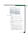
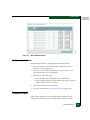
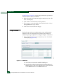
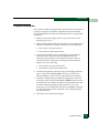
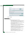
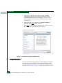
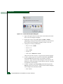
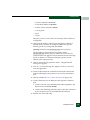
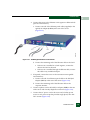
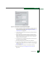
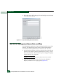
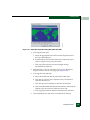
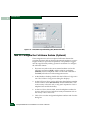
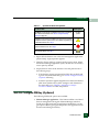
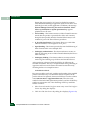
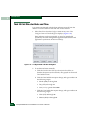
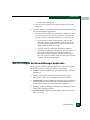
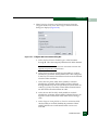
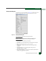
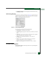
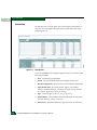
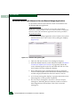
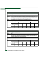
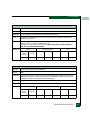
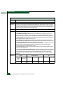
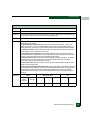
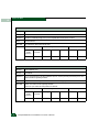
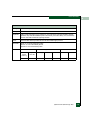
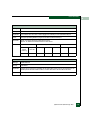
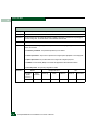
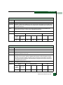
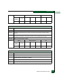
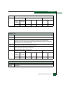
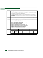
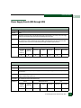
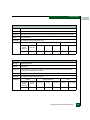
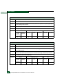
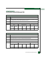
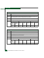
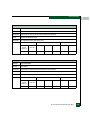
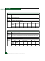
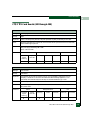
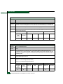
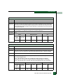
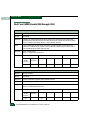
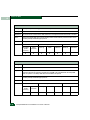
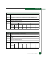
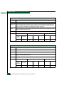
Repair Information
4
Event Log
The Event Log records simple network management protocol (SNMP)
trap events, client-server communication errors, and other problems
recorded by the SAN management application. Information provided
is generally intended for use by third-level support personnel to fault
isolate significant problems.
The log describes:
•
Date/Time - The date and time the event occurred.
•
Event - An event number and brief description of the event.
Include this information when reporting the event to customer
support.
•
Product - The product associated with the event and configured
name or internet protocol (IP) address associated with the
instance are displayed.
•
Data - Additional event data for fault isolation. Include this
information when fault isolating a call-home problem, or include
the information when reporting an event to customer support.
Fabric Log
The Fabric Log records the time and nature of changes made to a
multiswitch fabric. The information is useful for isolating zoning or
fabric-wide problems.
The log describes:
•
Date/Time - The date and time the change occurred.
•
Fabric Event - The description of the zoning or fabric change.
•
Description - Supplementary information (if available) in text
format.
Product Status Log
The Product Status Log records the previous and current status of a
managed product, and indicates the instance of an Element Manager
application that should be opened to investigate a problem.
The log describes:
•
4-4
Date/Time - The date and time the director status change
occurred.
Intrepid® 6064 Director Installation and Service Manual
Repair Information
4
•
Network Address - The IP address or configured name of the
director. This address or name corresponds to the address or
name displayed under the product icon at the physical map.
•
Previous Status - The status of the director prior to the reported
status change (Operational, Degraded, Failed, OutofBand Online, or
Unknown). An Unknown status indicates the SAN management
application cannot communicate with the director.
•
New Status - The status of the director after the reported status
change (Operational, Degraded, Failed, OutofBand Online, or
Unknown).
Element Manager Logs
The Element Manager application provides access to logs that contain
switch-level maintenance information. At any application view, click
(select) the desired log option from the Logs menu.
Event Log
The Event Log records events or errors. Entries reflect the status of the
management interface and managed product.
The log describes:
•
Date/Time - The date and time the event occurred.
•
Event - The three-digit event code associated with the event. See
Appendix A, Event Code Tables for an explanation of event codes.
•
Description - A brief description of the event.
•
Severity - The severity of the event (Informational, Minor, Major, or
Fatal).
•
FRU-Position - An acronym representing the FRU type, followed
by a number representing the FRU chassis position.
•
Event Data - Supplementary event data (if available) in
hexadecimal format. See Appendix A, Event Code Tables for an
explanation of the supplementary event data.
Hardware Log
The Hardware Log records a history of FRU removals and
replacements (insertions) for the director.
The log describes:
Obtaining Log Information
4-5
Repair Information
4
•
Date/Time - The date and time the FRU was inserted or removed.
•
FRU - An acronym representing the FRU type.
•
Position - A number representing the FRU chassis position. The
chassis (slot) position for a nonredundant FRU is 0. The chassis
positions for redundant FRUs are 0 and 1.
•
Action - The action performed (Inserted or Removed).
•
Part Number - The part number of the inserted or removed FRU.
•
Serial Number - The serial number of the inserted or
removed FRU.
Link Incident Log
The Link Incident Log records Fibre Channel link incident events and
causes.
The log describes:
•
Date/Time - The date and time the link incident occurred.
•
Port - The port number that reported the link incident.
•
Link Incident - A brief description of the link incident and cause,
including:
— Implicit incident.
— Bit-error threshold exceeded.
— Loss of signal or loss of synchronization.
— Not-operational primitive sequence received.
— Primitive sequence timeout.
— Invalid primitive sequence received for current link state.
See MAP 0500: Port Failure or Link Incident Analysis on page 3-34 for
corrective actions.
Port Threshold Alert Log
The Port Threshold Alert Log records a history of threshold alert
notifications.
The log describes:
4-6
•
Date/Time - The date and time stamp for when the alert occurred.
•
Name - The name for the alert as configured through the
Configure Threshold Alerts dialog box.
Intrepid® 6064 Director Installation and Service Manual
Repair Information
4
•
Port - The port number where the alert occurred.
•
Type - The type of alert: transmit (Tx) or receive (Rx).
•
Utilization % - The percent usage of traffic capacity. This setting
constitutes the threshold value and is configured through the
Configure Threshold Alerts dialog box. For example, a value of 25
means that threshold occurs when throughput reaches 25 percent
of the port capacity.
•
Interval - The time interval during which the throughput is
measured and an alert can generate. This is set through the
Configure Threshold Alerts dialog box.
Open Trunking Log
The Open Trunking Log records ISL congestion events that cause Fibre
Channel traffic to be routed through an alternate ISL. Entries reflect
the traffic re-route status at the director.
The log describes:
•
Date/Time - The date and time the re-route action occurred.
•
Receive Port - The director port number (decimal) used for
receiving Fibre Channel traffic after the re-route action.
•
Target Domain - The domain ID (decimal) of the target device to
which Fibre Channel traffic from the director was rerouted.
•
Old Exit Port - The director port number (decimal) used for
transmitting Fibre Channel traffic before the re-route action.
•
New Exit Port - The director port number (decimal) used for
transmitting Fibre Channel traffic after the re-route action.
Imbedded Port Log
The Embedded Port Log records all Fibre Channel frames transmitted
through the product embedded port, including Class F traffic, fabric
logins, state change notifications, and exception frames. The
information is useful for Fibre Channel frame debugging (usually
performed by second-level support).
The log describes:
•
Date/Time - The date and time frame was transmitted through
the embedded port.
•
Port - The Fibre Channel port number (decimal) transmitting
frame through the embedded port.
Obtaining Log Information
4-7
Repair Information
4
•
Direction - The Fibre Channel frame direction (In or Out).
•
Frame Header - 24-byte frame header (hexadecimal).
•
Length - The size of frame payload in bytes.
•
Payload - First 32 bytes of frame payload (hexadecimal).
•
SOF - The start of frame character (hexadecimal).
•
EOF - The end of frame character (hexadecimal).
NOTE: Identical entries are recorded in the wrapping and non-wrapping
logs. When the non-wrapping log fills, old records are overwritten. The
wrapping log preserves all records.
Switch Fabric Log
The Switch Fabric Log records the time and nature of changes made to
a multiswitch fabric that affect this product.
The log describes:
•
Date/Time - The date and time the change occurred. Timing
granularity is provided to one hundredth of a second.
•
Description - The description of the zoning or fabric change.
•
Event Data - Supplementary event data that provides additional
information that varies according to the even logged.
•
Ports (RSCN only) - The list of product ports affected by
registered state change notifications (RSCNs) related to the event.
NOTE: Identical entries are recorded in the wrapping and non-wrapping
logs. When the non-wrapping log fills, old records are overwritten. The
wrapping log preserves all records.
EFCM Basic Edition Logs
Select the desired log from the Logs menu at any time.
Event Log
The Event Log displays events or errors. Entries reflect the status of
the interface and managed director.
The log describes:
•
4-8
Date/Time - The date and time the event occurred.
Intrepid® 6064 Director Installation and Service Manual
Repair Information
4
•
Error Code - The three-digit code that describes the event
(Appendix A, Event Code Tables).
•
Severity - The severity of the event (Informational, Minor, Major, or
Severe).
•
Event Data - Supplementary information (if available) in
hexadecimal format (Appendix A, Event Code Tables).
Link Incident Log
The Link Incident Log records Fibre Channel link incident events and
causes.
The log describes:
•
Date/Time - The date and time the link incident occurred.
•
Port - The port number that reported the link incident.
•
Link Incident Event - A brief description of the link incident and
cause, including:
— Implicit incident.
— Bit-error threshold exceeded.
— Loss of signal or loss of synchronization.
— Not-operational primitive sequence received.
— Primitive sequence timeout.
— Invalid primitive sequence received for current link state.
See MAP 0500: Port Failure or Link Incident Analysis on page 3-34 for
corrective actions.
Open Trunking Re-Route Log
The Open Trunking Re-Route Log records interswitch link (ISL)
congestion events that cause Fibre Channel traffic to be routed
through an alternate ISL. Entries reflect the traffic re-route status at
the managed director.
The log describes:
•
Date/Time - The date and time the re-route action occurred.
•
Receive Port - The director port number (decimal) used for
receiving Fibre Channel traffic after the re-route action.
•
Target Domain - The domain ID (decimal) of the target device to
which Fibre Channel traffic from the director was rerouted.
Obtaining Log Information
4-9
Repair Information
4
•
Old Exit Port - The director port number (decimal) used for
transmitting Fibre Channel traffic before the re-route action.
•
New Exit Port - The director port number (decimal) used for
transmitting Fibre Channel traffic after the re-route action.
Fabric Log
The Fabric Log records the time and nature of changes made to a
multiswitch fabric. The information is useful for isolating zoning or
fabric-wide problems.
The log describes:
•
Count - The cumulative count of log entries (wrapping or
non-wrapping).
•
Date/Time - The date and time the change occurred.
•
Description - The description of the zoning or fabric change.
•
Data - Supplementary information (if available) in text format.
NOTE: Identical entries are recorded in the wrapping and non-wrapping
logs. When the non-wrapping log fills, old records are overwritten. The
wrapping log preserves all records.
Embedded Port Frame Log
The Embedded Port Frame Log records all Fibre Channel frames
transmitted through the product embedded port, including Class F
traffic, fabric logins, state change notifications, and exception frames.
The information is useful for Fibre Channel frame debugging
(usually performed by second-level support.
The log describes:
4-10
•
Count - The cumulative count of log entries (wrapping or
non-wrapping).
•
Date/Time - The date and time frame was transmitted through
the embedded port.
•
Port # - The Fibre Channel port number (decimal) transmitting
frame through the embedded port.
•
Direction - The Fibre Channel frame direction - incoming (I) or
outgoing (O).
•
SOF - The start of frame character (hexadecimal).
Intrepid® 6064 Director Installation and Service Manual
Repair Information
4
•
EOF - The end of frame character (hexadecimal).
•
Payload Size - The size of frame payload in bytes.
•
Header - 24-byte frame header (hexadecimal).
•
Payload - The first 32 bytes of frame payload (hexadecimal).
Obtaining Port Diagnostic Information
Fibre Channel port diagnostic information can be obtained by:
•
Inspecting port LEDs at the port card faceplates or emulated port
LEDs at the Element Manager Hardware View.
•
Inspecting parameters at the Element Manager application.
•
Inspecting parameters at the EFCM Basic Edition interface.
Port LED Diagnostics
To obtain port operational information, inspect port LEDs at the
director port card faceplate or the emulated port LEDs at the Element
Manager Hardware View. These port operational states are defined in
Table 4-2.
Table 4-2
Port Operational States
Port
State
Green
LED
Amber
LED
Alert
Symbol
Description
Online
On
Off
None
An attached device is connected to the director and
ready to communicate, or is communicating with other
attached devices. If the port remains online, the green
port LED remains illuminated. At the director port card,
the green LED blinks when there is Fibre Channel traffic
through the port.
Offline
Off
Off
None
The director port is blocked and transmitting the offline
sequence (OLS) to the attached device.
Off
Off
Yellow Triangle
The director port is unblocked and receiving the OLS,
indicating the attached device is offline.
Beaconing
Off or On
Blinking
Yellow Triangle
The port is beaconing. The amber port LED blinks once
every two seconds to enable users to locate the port.
Invalid
Attachment
On
Off
Yellow Triangle
The director port has an invalid attachment state. The
reasons for this state display in the Reasons field of the
Port Properties dialog box.
Obtaining Port Diagnostic Information
4-11
Repair Information
4
Table 4-2
Port Operational States (continued)
Port
State
Green
LED
Amber
LED
Alert
Symbol
Description
Link
Incident
Off
Off
Yellow Triangle
A link incident occurred on the port. The alert symbol
appears at the Port Card View, Port List View, and
Hardware View.
Link Reset
Off
Off
Yellow Triangle
The director and attached device are performing a link
reset operation to recover the link connection. This is a
transient state that should not persist.
No Light
Off
Off
None
No signal (light) is received by the director port. This is a
normal condition when there is no cable attached to the
port or when the attached device is powered off.
Inactive
On
Off
Yellow Triangle
The port is inactive. The reason appears in the Reason
field at the Port Properties dialog box.
Not
Installed
Off
Off
None
An optical transceiver is not installed in the director port.
Not
Operational
Off
Off
Yellow Triangle
The director port is receiving the not operational
sequence (NOS) from an attached device.
Port Failure
Off
On
Red and Yellow
Blinking Diamond
The director port failed and requires service.
Segmented
E_Port
On
Off
Yellow Triangle
The E_Port is segmented, preventing two connected
directors from joining and forming a multiswitch
fabric.The reasons for the segmentation display in the
Reasons field of the Port Properties dialog box.
Testing
Off
Blinking
Yellow Triangle
The port is performing an internal loopback test.
On
Blinking
Yellow Triangle
The port is performing an external loopback test.
Element Manager Application Diagnostics
To obtain port operational information at the Element Manager
application, inspect parameters at the:
4-12
•
Port List View.
•
Performance View.
•
Port Properties dialog box.
•
Port Technology dialog box.
Intrepid® 6064 Director Installation and Service Manual
Repair Information
4
Port List View
To open the Port List View, click the Port List tab at any view
(Figure 4-1). A row of information for each port appears.
Figure 4-1
Port List View
The view provides the following information:
•
Port # - The director port number.
•
FC Addr - The director logical port address (hexadecimal format).
•
Name - The user-defined name or description for the port.
•
Block Config - Indicates if a port is blocked or unblocked.
•
State - The port state (Online, Offline, Testing, Beaconing, Invalid
Attachment, Link Incident, Link Reset, No Light, Not Operational, Port
Failure, Segmented E_Port, or Testing).
•
Type - The type of port (G_Port, F_Port, or E_Port).
•
Operating Speed - The operating speed of the port (Not
Established, 1 Gbps, or 2 Gbps).
•
Alert - If link Incident (LIN) alerts are configured, a yellow
triangle appears in the column when a link incident occurs. A
yellow triangle also appears if beaconing is enabled. A red and
yellow diamond appears if the port fails.
Performance View
To open the Performance View, click the Performance tab at any other
view.
Bar graphs at the top of the view display instantaneous transmit or
receive activity level for each port. The relative value displayed is the
greater of the transmit or receive activity. Each graph has 20 green-bar
Obtaining Port Diagnostic Information
4-13
Repair Information
4
level indicators corresponding to 5% of maximum port throughput. If
any activity is detected, at least one green bar appears. A red
indicator on each bar graph (high-water mark) remains at the highest
level reached since the port was set online. In addition, the following
statistical information appears:
4-14
•
Class 2 Statistics - These statistics include the number of 4-byte
words transmitted and received, and the number of Class 2
frames transmitted, received, busied, or rejected.
•
Class 3 Statistics - These statistics include the number of 4-byte
words transmitted and received, and the number of Class 3
frames transmitted, received, or discarded.
•
Error Statistics - These statistics include the number of link
failures; synchronization and signal losses; discarded frames;
invalid transmission words; primitive sequence, CRC, delimiter,
and address identification errors; and short frames.
•
Operational Statistics - These statistics include the number of
offline sequences transmitted and received; and link resets
transmitted and received.
•
Traffic Statistics - These statistics include port transmit and
receive values for frames, four-byte words, and link utilization
percentage. The number of traffic flows rerouted to or from an ISL
due to congestion is also reported.
Intrepid® 6064 Director Installation and Service Manual
Repair Information
4
Port Properties Dialog Box
To open the Port Properties dialog box (Figure 4-2), double-click a port
graphic at the Hardware View or a port row at the Port List View.
Figure 4-2
Port Properties Dialog Box
The dialog box provides the following information:
NOTE: If the Open Trunking feature is installed, an additional item,
Congested Threshold %, appears in the Port Properties dialog box.
•
Port Number - The director port number.
•
Port Name - The user-defined name or description for the port.
•
Type - The port type (G_Port, F_Port, or E_Port).
•
Technology - The type of port transceiver and optical cable
installed.
•
Operating Speed - The operating speed of the port (Not
Established, 1 Gbps, or 2 Gbps).
•
Fibre Channel Address - The logical port address (hexadecimal
format). Not applicable for E_Ports.
Obtaining Port Diagnostic Information
4-15
Repair Information
4
4-16
•
Port WWN - The Fibre Channel WWN of the port.
•
Attached Port WWN - The Fibre Channel WWN of the device
attached to the port.
•
Block Configuration - A user-configured state for the port
(Blocked or Unblocked).
•
10 - 100 km Configuration - The user-configured state for
extended distance operation (On or Off).
•
Rx BB_Credits Configured - The user-defined number of receive
BB_Credits allocated to the port.
•
NPIV Login Limit Configured - With N_Port ID virtualization
(NPIV) enabled, the user-defined maximum number of virtual
addresses assigned to the physical port.
•
Logged in IDs - The number of virtual addresses logged in to the
physical port.
•
LIN Alerts Configuration - A user-specified state for the port (On
or Off).
•
FAN Configuration - A user-configured state for FAN
configuration (Enabled or Disabled).
•
Beaconing - User-specified for the port (On or Off). When
beaconing is enabled, a yellow triangle appears adjacent to the
status field.
•
Link Incident - If no link incidents are recorded, None appears in
the status field. If a link incident is recorded, a summary appears
describing the incident, and a yellow triangle appears adjacent to
the status field.
•
Operational State - The state of the port (Online, Offline,
Beaconing, Invalid Attachment, Link Incident, Link Reset, No Light,
Not Operational, Port Failure, Segmented E_Port, or Testing). A
yellow triangle appears adjacent to the status field if the port is in
a non-standard state that requires attention. A red and yellow
diamond appears adjacent to the status field if the port fails.
•
Reason - A summary appears describing the reason if the port
state is Segmented E_Port, Invalid Attachment, or Inactive. For any
other port state, the reason field is blank or N/A.
•
Threshold Alert- If a threshold alert exists for the port, an alert
indicator (yellow triangle) and the configured name for the alert
appear.
Intrepid® 6064 Director Installation and Service Manual
Repair Information
4
•
Zoning Enforcement - The zoning policy enforced (Hard Zoning,
Soft Zoning, or N/A).
Port Technology Dialog Box
To open the Port Technology dialog box (Figure 4-3), right-click a port
graphic at the Hardware View or a port row at the Port List View, then
select Port Technology from the pop-up menu.
Figure 4-3
Port Technology Dialog Box
The dialog box provides the following information:
•
Port Number - The director port number.
•
Connector type - Type of port connector (LC, Unknown, or Internal
Port).
•
Transceiver - Type of port transceiver (Shortwave Laser, Longwave
Laser, Long Distance Laser, Unknown, or None).
•
Distance - Port transmission distance (<=50m, 50M - 2k,
2k - 10k, 10k=>).
•
Media - Type of optical cable used (Singlemode, multimode
50-micron, multimode 62.5-micron, or Unknown).
•
Speed - Operating speed (Not Established, 1 Gbps, or 2 Gbps).
EFCM Basic Edition Diagnostics
The EFCM Basic Edition interface provides access to port diagnostic
information, as well.
Obtaining Port Diagnostic Information
4-17
Repair Information
4
Port List View
To open the Port List View, select Port List from the Product menu at
any view. As an example, the figure shows POM data in the lower
panel (Figure 4-4).
Figure 4-4
Port List View
A row of information for each port appears. Each row consists of the
following columns:
4-18
•
Port - The director port number.
•
Name - The user-defined name or description for the port.
•
Block Configuration - Indicates if a port is blocked or unblocked.
•
Operational State - Port state (Online, Offline, Not Installed,
Inactive, Invalid Attachment, Link Reset, No Light, Not Operational,
Port Failure, Segmented E_Port, or Testing).
•
Type - The Port type (G_Port, F_Port, or E_Port) ).
•
Health Status - The condition of the installed optical transceiver
(Normal, Warning, Alarm, or No Info).
•
Transceiver - Installed transceiver type (SFP, XFP, or Unknown).
Intrepid® 6064 Director Installation and Service Manual
Repair Information
4
Inspect Port Properties
At the Port List View, click a physical port number listed in the Port
column. Physical properties for the selected port appear in the lower
panel of the view:
•
Port Number - The director port number.
•
Port Name - The user-defined name or description for the port.
•
Port Type - The user-defined port type (G_Port, F_Port, or E_Port).
•
Operating Speed - The port operating speed (Not Established, 1
Gbps, or 2 Gbps).
•
Fibre Channel Address - The port FC address identifier. Port FC
address if the port was swapped.
•
Port WWN - The Fibre Channel world wide name (WWN) of the
port.
•
Attached Port WWN - The Fibre Channel WWN of the device
attached to the port.
•
Block Configuration - The user-configured state for the port
(Blocked or Unblocked).
•
Beaconing - The user-specified for the port (On or Off).
•
FAN Configuration - The user-configured state for fabric address
notification (FAN) configuration (Enabled or Disabled).
•
Operational State - The Port state (Online, Offline, Not Installed,
Inactive, Invalid Attachment, Link Reset, No Light, Not Operational,
Port Failure, Segmented E_Port, Disabled, or Testing).
•
Reason - A summary appears describing the reason if the port
state is Segmented E_Port, Invalid Attachment, or Inactive. For any
other port state, the reason is N/A.
Inspect POM Data
At the Port List View, click the entry for a port in the Health Status
column. POM data for the selected port appears in the lower panel of
the view (Figure 4-4):
•
Port Number - The director port number.
•
Health Status - The condition of the installed optical transceiver
(Normal, Warning, Alarm, or No Info).
Obtaining Port Diagnostic Information
4-19
Repair Information
4
•
Transceiver Type - The installed transceiver type (SFP, XFP, or
Unknown).
If the port has a digital diagnostics (DD) enabled optical transceiver
installed, product firmware displays a table of reported temperature,
voltage, current, transceiver power, and receiver power. Optical
transceivers also provide vendor-specific threshold values for these
parameters.
Inspect Port Transceiver Technology
At the Port List View, click the entry for a port in the Transceiver
column. Port transceiver technology information for the selected port
appears in the lower panel of the view:
•
Port Number - The director port number.
•
Identifier - Installed transceiver type (SFP, XFP, or Unknown).
•
Connector type - The type of port connector (LC, MT_RJ, MU,
Unknown, or Internal Port).
•
Transceiver - The type of port transceiver (Shortwave Laser,
Longwave Laser, Long Distance Laser, Unknown, or None).
•
Distance Capability - The port transmission distance (Short,
Intermediate, Long, Very Long, or Unknown).
•
Media - The type of optical cable used (Singlemode, multimode
50-micron, multimode 62.5-micron, or Unknown).
•
Speed - The operating speed (Not Established, 1 Gbps, or 2 Gbps).
Performance View
The EFCM Basic Edition interface provides access to port statistics
information through the Performance View. To open this view, select
Performance from the Product menu at any other view. The following
statistical information appears:
•
4-20
Traffic Statistics - These statistics include port transmit and
receive values for frames; four-byte words; offline sequences; link
resets; and link utilization percentage. The time spent using no
transmission buffer-to-buffer credit (BB_Credit) is also reported.
Intrepid® 6064 Director Installation and Service Manual
Repair Information
4
•
Error Statistics - These statistics include the number of link
failures; synchronization and signal losses; discarded frames;
invalid transmission words; primitive sequence, cyclic
redundancy check (CRC), delimiter, and address identification
errors; and short frames.
•
Class 2 Statistics - These statistics include the number of 4-byte
words transmitted and received, and the number of Class 2
frames transmitted, received, busied, or rejected.
•
Class 3 Statistics - These statistics include the number of 4-byte
words transmitted and received, and the number of Class 3
frames transmitted, received, or discarded.
•
Open Trunking Statistics - These statistics include the number of
traffic flows rerouted to or from an ISL due to congestion.
Performing Loopback Tests
Port diagnostics consist of internal and external loopback tests. The
tests are performed on any selected port at the Element Manager
application or at the EFCM Basic Edition interface. The tests are:
•
Internal loopback test - An internal loopback test checks port
card circuitry, but does not check fiber-optic components of a port
transceiver. The test is performed with a device attached to the
port, but the test momentarily blocks the port and is disruptive to
the attached device.
•
External loopback test - An external loopback test checks port
card circuitry, including fiber-optic components of a port
transceiver. To perform the test, the attached device must be
quiesced and disconnected from the port, and a multimode or
singlemode loopback plug must be inserted in the port receptacle.
Internal Loopback Test (Element Manager Application)
To perform an internal loopback at the Element Manager application:
1. Notify the customer that a disruptive internal loopback test will
be performed. Ensure the system administrator quiesces Fibre
Channel frame traffic and sets attached devices offline.
Performing Loopback Tests
4-21
Repair Information
4
NOTE: At the start of the loopback test, the port or port card can be
online, offline, blocked, or unblocked.
NOTE: An optical transceiver (SFP or XFP) must be installed in the port
during the test. A device can remain connected during the test.
2. At the Element Manager application, select Port Diagnostics from
the Maintenance menu. The Port Diagnostics dialog box displays
(Figure 4-5).
3. Type the port number to be tested or select all ports at the Port
Select area of the dialog box.
4. At the Diagnostics Test list box, select the Internal Loop option.
5. Click Next. The message Press START TEST to begin diagnostics
appears, and the Next button changes to a Start Test button.
Figure 4-5
Port Diagnostics Dialog Box
6. Click Start Test. The test begins and:
a. The Start Test button changes to a Stop Test button.
b. The message Port xx: TEST RUNNING appears.
c. A red progress bar (indicating percent completion) travels
from left to right across the Completion Status field.
7. When the test completes, results appear as Port xx: Passed! or
Port xx: Failed! in the message area of the dialog box.
4-22
Intrepid® 6064 Director Installation and Service Manual
Repair Information
4
8. When finished, click Cancel to close the Port Diagnostics dialog
box.
9. Reset the port:
a. At the Hardware View, right-click the port graphic. A pop-up
menu appears.
b. Select Reset Port. A message box displays, indicating a link
reset will occur.
c. Click OK. The port resets.
10. Notify the customer that the test is complete and the attached
device can be set online.
External Loopback Test (Element Manager Application)
To perform an external loopback at the Element Manager application:
1. Notify the customer that a disruptive external loopback test will
be performed and the attached device must be disconnected.
2. Disconnect the fiber-optic jumper cable from the port to be tested.
3. Depending on the port technology, insert a singlemode or
multimode loopback plug into the port receptacle.
4. At the Element Manager application, select Port Diagnostics from
the Maintenance menu. The Port Diagnostics dialog box displays
(Figure 4-5).
5. Type the port number to be tested or select all ports at the Port
Select area of the dialog box.
6. At the Diagnostics Test list box, select the External Loop option.
7. Click Next. At the Port Diagnostics dialog box, the message
Loopback plug(s) must be installed on ports being diagnosed
appears.
8. Verify a loopback plug is installed and click Next. The message
Press START TEST to begin diagnostics appears, and the Next
button changes to a Start Test button.
9. Click Start Test. The test begins and:
a. The Start Test button changes to a Stop Test button.
b. The message Port xx: TEST RUNNING appears.
Performing Loopback Tests
4-23
Repair Information
4
c. A red progress bar (indicating percent completion) travels
from left to right across the Completion Status field.
10. When the test completes, results appear as Port xx: Passed! or
Port xx: Failed! in the message area of the dialog box.
11. When finished, click Cancel to close the Port Diagnostics dialog
box.
12. Remove the loopback plug and reconnect the fiber-optic jumper
cable from the device to the port.
13. Reset the port:
a. At the Hardware View, right-click the port graphic. A pop-up
menu appears.
b. Select Reset Port. A message box displays, indicating a link
reset will occur.
c. Click OK. The port resets.
14. Notify the customer the test is complete and the device can be
reconnected to the switch and set online.
Internal Loopback Test (EFCM Basic Edition)
To perform an internal loopback at the EFCM Basic Edition interface:
1. Notify the customer that a disruptive internal loopback test will
be performed. Ensure the system administrator quiesces Fibre
Channel frame traffic through the port and sets attached device
offline.
NOTE: An optical transceiver (SFP or XFP) must be installed in the port
during the test. A device can remain connected during the test.
2. At the EFCM Basic Edition interface, select Ports and Diagnostics
from the Maintenance menu at any view. The Diagnostics View
displays (Figure 4-6).
4-24
Intrepid® 6064 Director Installation and Service Manual
Repair Information
4
Figure 4-6
Diagnostics View
3. Type the port number to be tested in the Targeted Port Number
field.
4. At the Diagnostic Test list box, select the Internal Loopback option.
5. Click Start. The test begins and:
a. The Diagnostics View changes to a Diagnostics - Executing View.
b. The message Diagnostics Time Remaining: xx appears,
where xx are the seconds remaining in the test. The test takes
approximately 30 seconds.
NOTE: Click Stop at any time to abort the loopback test.
6. When the test completes, the Diagnostics - Executing View reverts
to the Diagnostics View. Test results appear as Passed, Failed, or
Test Incomplete in the message area of the view.
7. Reset the tested port:
a. Select Ports and Reset from the Maintenance menu at any view.
The Reset View displays.
b. For the tested port, click the check box in the Reset column. A
check mark in the box indicates the port reset option is
enabled.
Performing Loopback Tests
4-25
Repair Information
4
c. Click OK at the bottom of the page. The port resets and the
message Your changes have been successfully activated.
appears.
8. Notify the customer that the test is complete and the attached
device can be set online.
External Loopback Test (EFCM Basic Edition)
To perform an external loopback at the EFCM Basic Edition interface:
1. Notify the customer that a disruptive external loopback test will
be performed and that the attached device must be disconnected.
2. Disconnect the fiber-optic jumper cable from the port to be tested.
3. Depending on the port technology, insert a singlemode or
multimode loopback plug into the port receptacle.
4. At the EFCM Basic Edition interface, select Ports and Diagnostics
from the Maintenance menu at any view. The Diagnostics View
displays (Figure 4-6).
5. Type the port number to be tested in the Targeted Port Number
field.
6. At the Diagnostic Test list box, select the External Loopback option.
7. Click Start. The test begins and:
a. The Diagnostics View changes to a Diagnostics -Executing View.
b. The message Diagnostics Time Remaining: xx appears,
where xx are the seconds remaining in the test. The test takes
approximately 30 seconds.
NOTE: Click Stop at any time to stop the loopback test.
8. When the test completes, the Diagnostics - Executing View reverts
to the Diagnostics View. Test results appear as Passed, Failed, or
Test Incomplete in the message area of the view.
9. Remove the loopback plug and reconnect the fiber-optic jumper
cable from the device to the port.
10. Reset the tested port:
a. Select Ports and Reset from the Maintenance menu at any view.
The Reset View displays.
4-26
Intrepid® 6064 Director Installation and Service Manual
Repair Information
4
b. For the tested port, click the check box in the Reset column. A
check mark in the box indicates the port reset option is
enabled.
c. Click OK at the bottom of the page. The port resets and the
message Your changes have been successfully activated.
appears.
11. Notify the customer the test is complete and the device can be
reconnected to the director and set online.
Blocking and Unblocking Ports
This section describes procedures to block or unblock director ports.
An entire port card can be blocked or unblocked, or ports can be
blocked or unblocked on an individual basis. When a port is blocked,
the port is automatically set offline. When a port is unblocked, the
port is automatically set online.
NOTE: When a director port is blocked, the operation of an attached Fibre
Channel device is disrupted. Do not block director ports unless directed to do
so by a procedural step or the next level of support.
Block or Unblock a Port or Port Card (Element Manager Application)
To block or unblock a port or port card from the Element Manager
application:
1. At the Element Manager application, click the Hardware tab. The
Hardware View for the selected director displays.
2. Move the cursor over the port or port card to be blocked or
unblocked and right-click to open a list of menu options. Perform
one of the following:
— To block a port or port card: Select the Block Port or Block All
Ports menu option. A Warning dialog box displays. Click OK.
The dialog box closes and the following occur to indicate the
port or port card is blocked and offline:
• At the director, the green port (or ports) LED extinguishes.
• At the Hardware View, the emulated green port (or ports)
LED extinguishes.
Blocking and Unblocking Ports
4-27
Repair Information
4
• A check mark appears adjacent to the Block Port or Block All
Ports menu option.
— To unblock a port or port card: Select the Block Port or Block
All Ports menu option. Note the check mark in the box
adjacent to the menu item, indicating the port or port card is
blocked. A Warning dialog box displays. Click OK. The dialog
box closes and the following occur to indicate the port is
unblocked and online:
• At the director, the green port (or ports) LED illuminates.
• At the Hardware View, the emulated green port (or ports)
LED illuminates.
• The box adjacent to the Block Port or Block All Ports menu
option becomes blank.
Block or Unblock a Port (EFCM Basic Edition)
To block or unblock a port from the EFCM Basic Edition interface:
1. At the EFCM Basic Edition interface, select Ports and Basic Info
from the Configure menu at any view. The Basic Information View
displays (Figure 4-7).
4-28
Intrepid® 6064 Director Installation and Service Manual
Repair Information
4
Figure 4-7
Basic Information View
2. Perform one of the following:
— Click the check box for the selected port in the Blocked column
to block the port or ports. A check mark in the box indicates
the port is blocked.
— Click the check box for the selected port in the Blocked column
to remove the check mark and unblock the port or ports. A
blank box indicates the port is unblocked.
3. Click OK at the bottom of the page to save and activate the
change. The message Your changes have been successfully
activated. appears.
Swapping Ports
Failure of port circuitry behind an optical transceiver may require
swapping the logical port address of the failed port to a known
operational port. This ensures the port address matches information
in the hardware configuration definition (HCD) of an attached host.
NOTE: This procedure swaps hexadecimal logical port addresses, not
decimal port numbers.
To swap ports:
1. At the Element Manager application, select Swap Ports from the
Maintenance menu. The Swap Ports dialog box displays
(Figure 4-8).
Swapping Ports
4-29
Repair Information
4
Figure 4-8
Swap Ports Dialog Box
2. Select the radio button associated with the product management
style and enter the decimal port numbers (open systems style) or
hexadecimal port addresses (FICON style) of the ports to be
swapped. The FC Address fields update dynamically.
3. Click Next. The Instructions section of the dialog box indicates the
ports will be blocked.
4. Notify the customer that a port swap will be performed. Ensure
the system administrator quiesces Fibre Channel frame traffic
through the ports, varies any attached host offline, and sets any
attached device offline.
5. Click Next. Beaconing is enabled for both ports and both ports are
blocked. Swap the port fiber-optic cables as directed by the
system administrator.
6. Click Next. The Instructions section of the dialog box indicates the
port swap operation is complete and beaconing is disabled. Select
each Unblock check box to unblock the ports, then click Finish.
7. Ensure the system administrator varies any attached host online
and sets any attached device online.
8. Back up the product configuration data (Back Up Configuration
(Element Manager Application) on page 4-50).
4-30
Intrepid® 6064 Director Installation and Service Manual
Repair Information
4
Performing Channel Wrap Tests (FICON)
A channel wrap test is a diagnostic procedure that checks
host-to-director FICON link connectivity by returning the output of
the host as input. The test is host-initiated, and transmits ECHO
extended link service (ELS) command frames to a director port
enabled for channel wrapping. The director port echoes the frames
back to the host.
To perform a channel wrap test for a director-attached host:
1. Notify the customer a disruptive channel wrap test will be
performed on the host-to-director FICON link.
2. At the management server, open the EFC Manager application.
The Products View displays.
a. Double-click the icon representing the director for which the
channel wrap test will be configured. The Hardware View for
the selected director displays.
b. At the Hardware View, verify the location of the port to be
configured for the channel wrap test. When the mouse cursor
is passed over a graphical port card on the front view of the
director, the card highlights with a blue border and a pop-up
displays with the following information:
• Port card type (UPM).
• Chassis slot number.
• The consecutive port numbers on the selected card.
c. Double-click the port card with the port to be configured. The
Port Card View for the selected card displays.
d. Right-click the port to be configured, then select Channel Wrap
from the menu. The Channel Wrap On for Port n (where n is the
port number) window displays.
e. Click OK to enable channel wrapping for the port.
3. Perform the fibre link test at the S/390 host attached to the
configured port. For test instructions, refer to the service
documentation delivered with the S/390 system.
Performing Channel Wrap Tests (FICON)
4-31
Repair Information
4
Collecting Maintenance Data
When director operational firmware detects a critical error or FRU
failure, the director automatically copies the contents of dynamic
random access memory (DRAM) to a dump area in FLASH memory
on the active CTP card, then initiates a failover to the operational
FRU. The director then transfers (through the Ethernet connection)
the captured dump file from FLASH memory to the management
server hard drive.
NOTE: An optional full-volatility feature is often required at military sites
that process classified data. If the feature is enabled through a product feature
enablement (PFE) key, a memory dump file (that possibly includes classified
Fibre Channel frames) is not included as part of the data collection
procedure.
Perform the maintenance data collection procedure after a firmware
fault is corrected or a failed FRU is replaced to capture the data for
analysis. Maintenance data includes the dump file, hardware log,
audit log, and an engineering log viewable only by support
personnel.
Collecting Maintenance Data (Element Management Application)
To collect maintenance data (retrieve the dump file from the
management server hard drive) from the Element Manager
application:
1. At the Element Manager application, select Data Collection from
the Maintenance menu. The Save Data Collection dialog box
displays (Figure 4-9).
Figure 4-9
4-32
Save Data Collection Dialog Box
Intrepid® 6064 Director Installation and Service Manual
Repair Information
4
2. Remove the backup CD from the management server compact
disk-rewritable (CD-RW) drive and insert a blank rewritable CD.
3. At the Save Data Collection dialog box, select the compact disc
drive (D:\) from the Look in drop-down menu, type a descriptive
name for the collected maintenance data in the File name field,
then click Save.
4. The Data Collection dialog box displays with a progress bar that
shows percent completion of the data collection process. When
the process reaches 100%, the Cancel button changes to a Close
Button.
5. Click Close to close the dialog box.
6. Remove the CD with the newly-collected maintenance data from
the management server CD-RW drive. Return the CD with the
failed FRU to support personnel for failure analysis.
7. To ensure the backup application operates normally, replace the
original backup CD in the management server CD-RW drive.
Collecting Maintenance Data (EFCM Basic Edition)
To collect maintenance data from the EFCM Basic Edition application:
1. At the EFCM Basic Edition interface, select System Files from the
Maintenance menu at any view. The System Files View displays
(Figure 4-10).
Figure 4-10
System Files View
2. Right-click the Data Collection link to open a list of menu options.
Select the Save Target As menu option. The Save As dialog box
displays.
Collecting Maintenance Data
4-33
Repair Information
4
3. Insert a blank diskette in the floppy drive of the PC
communicating with the EFCM Basic Edition interface.
4. At the Save As dialog box, select the floppy drive (A:\) from the
Save in drop-down menu, type a descriptive name for the zipped
(.zip) dump file in the File name field, and click Save.
5. A Download dialog box displays, showing the estimated time
remaining to complete the download process. When finished, the
dialog box changes to a Download complete dialog box.
6. Click Close to close the dialog box.
7. Remove the diskette with the newly-collected maintenance data
from the PC floppy drive. Return the diskette with the failed FRU
to support personnel for failure analysis.
Powering the Director On or Off
This section describes procedures to power on or power off the
director.
Power-On Procedure
DANGER
Use the supplied power cords. Ensure the facility power receptacle is
the correct type, supplies the required voltage, and is properly
grounded.
NOTE: The director does not have a power switch. Therefore the director
powers on when its power cords are connected to facility or rack power.
To power on the director:
1. One alternating current (AC) power cord is required for each
power supply installed. Ensure power cord(s) connect facility
power to the input AC module at the bottom rear of the director.
NOTE: If two power cords are installed for high availability, plug the
cords into separate facility power circuits.
4-34
Intrepid® 6064 Director Installation and Service Manual
Repair Information
4
2. The director powers on and performs power-on self-tests
(POSTs). During POSTs:
— Amber LEDs on both CTP cards and all port cards illuminate
momentarily.
— Green LED on each CTP card (active and backup) and each
port card illuminate as the card is tested.
— Green LEDs associated with Fibre Channel ports sequentially
illuminate as the ports are tested.
3. After successful POST completion, the green power LED on the
front bezel, green LED on the active CTP card, and green PWR
OK LEDs on both power supplies remain illuminated.
4. If a POST error or other malfunction occurs, go to Chapter 3,
Maintenance Analysis Procedures (MAPS) to isolate the problem.
NOTE: When powering on the director after removing and replacing a
faulty FRU, the amber system error LED may remain illuminated. Clear
the system error LED as part of the replacement procedure.
Power-Off Procedure
Powering the director off and on (performing a power cycle) resets all
logic cards and executes POSTs. When performing a power cycle, wait
approximately 30 seconds before switching power on.
NOTE: When the director is powered off, the operation of attached Fibre
Channel devices is disrupted. Do not power off the director unless directed to
do so by a procedural step or the next level of support.
To power off the director:
1. Notify the customer the director will be powered off. Ensure the
customer system administrator quiesces Fibre Channel frame
traffic through the director and sets attached devices offline.
2. Set the director offline (Setting the Director Online or Offline on
page 4-36).
3. Remove the director power cords from facility power. The
director powers off.
Powering the Director On or Off
4-35
Repair Information
4
4. If servicing the director, disconnect power cord(s) from the input
AC module at the bottom rear of the director. This step is not
required when performing a power cycle.
Setting the Director Online or Offline
This section describes procedures to set the director online or offline.
These operating states are described as:
•
Online - When the director is set online, an attached device can
log in to the director if the port is not blocked. Attached devices
can communicate with each other if they are configured in the
same zone.
•
Offline - When the director is set offline, all ports are set offline.
The director transmits the offline sequence (OLS) to attached
devices, and the devices cannot log in to the director.
NOTE: When the director is set offline, the operation of attached Fibre
Channel devices is disrupted. Do not set the director offline unless directed to
do so by a procedural step or the next level of support.
Set Online or Offline (Element Manager Application)
To set the director online or offline from the Element Manager
application:
1. At the Element Manager application, select Set Online State from
the Maintenance menu. The Set Online State dialog box displays
(Figure 4-11).
2. Perform one of the following:
— Click Set Online. A warning dialog box displays the message
"Performing this operation will change the current state to
Online". Click OK.
— Click Set Offline. A warning dialog box displays the message
"Performing this operation will change the current state to
Offline." Click OK.
4-36
Intrepid® 6064 Director Installation and Service Manual
Repair Information
4
Figure 4-11
Set Online State Dialog Box
Set Online or Offline (EFCM Basic Edition)
To set the director online or offline from the EFCM Basic Edition
interface:
1. At the EFCM Basic Edition interface, select Switch from the
Maintenance menu at any view. The Switch View displays
(Figure 4-12).
2. Perform one of the following:
— If the director is offline, click the green Activate button adjacent
to the Current Online State: field. The director comes online
and the message "Your changes have been successfully
activated." appears.
— If the director is online, click the green Deactivate button
adjacent to the Current Online State: field. The director goes
offline and the message "Your changes have been
successfully activated." appears.
Figure 4-12
Switch View
Setting the Director Online or Offline
4-37
Repair Information
4
IML, IPL, or Reset the Director
An IML or reset is performed at the CTP front panel using the IML or
the RESET button. An IPL is performed through the Element
Manager application. The EFCM Basic Edition interface does not
provide an IML, IPL, or director reset function.
ATTENTION! A reset should only be performed if a CTP card failure is
indicated. Do not reset the director unless directed to do so by a procedural
step or the next level of support.
An IML and IPL are functionally equivalent. The operations do not
cause power-on diagnostics to execute and are not disruptive to Fibre
Channel traffic. Both operations:
•
Reload director firmware from FLASH memory.
•
Reset the Ethernet LAN interface, causing the connection to the
management server to drop momentarily until the connection
automatically recovers.
A director reset is disruptive to Fibre Channel traffic and resets the:
•
Microprocessor and functional logic for the CTP card and reloads
the firmware from FLASH memory.
•
Ethernet LAN interface, causing the connection to the
management server to drop momentarily until the connection
automatically recovers.
•
Ports, causing all Fibre Channel connections to drop momentarily
until the connections automatically recover. This causes attached
devices to log out and log back in, therefore data frames lost
during director reset must be retransmitted.
IML the Director (CTP Front Panel)
To IML the director from the CTP front panel:
1. Press and hold the IML button for approximately three seconds.
2. During the IML, the director-to-management server Ethernet link
drops momentarily and the following occur at the Hardware View:
— As the network connection drops, the Intrepid 6140 Status table
turns yellow, the Status field displays No Link, and the State
field displays Link Timeout.
4-38
Intrepid® 6064 Director Installation and Service Manual
Repair Information
4
— The status bar at the bottom of the window displays a grey
square, indicating director status is unknown.
— Illustrated FRUs disappear, and appear again as the
connection is re-established.
IPL the Director (Element Manager Application)
To IPL the director from the Element Manager application:
1. At the Element Manager application, select the IPL option from
the Maintenance menu. An Information dialog box displays.
2. Click Yes to IPL the director. During the IPL, the
director-to-management server Ethernet link drops momentarily
and the following occur at the Hardware View:
— As the network connection drops, the Intrepid 6140 Status table
turns yellow, the Status field displays No Link, and the State
field displays Link Timeout.
— The status bar at the bottom of the window displays a grey
square, indicating director status is unknown.
— Illustrated FRUs disappear, and appear again as the
connection is re-established.
Reset the Director (CTP Front Panel)
To reset the director from the CTP front panel:
1. Press and hold the RESET button for approximately three
seconds.
2. During the reset:
— The green power (PWR) LED on the director front panel
illuminates.
— The amber system error (ERR) LED on the director front panel
blinks momentarily while the director is tested.
— The green LEDs associated with the Ethernet port blink
momentarily while the port is tested.
— The amber LEDs associated with the ports blink momentarily
while the ports are tested.
IML, IPL, or Reset the Director
4-39
Repair Information
4
— The director-to-management server Ethernet link drops
momentarily and the following occur at the Hardware View:
• As the network connection drops, the Intrepid 6140 Status
table turns yellow, the Status field displays No Link, and
the State field displays Link Timeout.
• The status bar at the bottom of the window displays a grey
square, indicating director status is unknown.
• Illustrated FRUs disappear, and appear again as the
connection is re-established.
Cleaning Fiber-Optic Components
Perform this procedure as directed in this publication and when
connecting or disconnecting fiber-optic cables from port optical
transceivers.
Tools required:
•
ESD grounding cable and wrist strap
•
Fiber-optic cleaning kit with:
— Oil-free compressed air or HFC-134a aerosol duster
— Alcohol-soaked cleaning pads.
Procedure:
CAUTION
Wear eye protection when using an aerosol duster.
To clean fiber-optic components:
ATTENTION! To avoid causing machine errors or damage while working on
the director, follow ESD procedures by connecting a grounding cable to the
director chassis and wearing an ESD wrist strap.
1. Follow ESD procedures by attaching a wrist strap to the director
chassis and your wrist.
2. Disconnect the fiber-optic cable from the port. Use an aerosol
duster to blow away any contaminants from the connector (part
A of Figure 4-13).
4-40
Intrepid® 6064 Director Installation and Service Manual
Repair Information
4
— Hold the duster upright and keep the air nozzle
approximately 50 millimeters (two inches) from the end of the
component.
— Blow compressed air or HFC-134a gas on the surfaces and end
of the connector for approximately five seconds.
Figure 4-13
Clean Fiber-Optic Components
3. Gently wipe the end-face and other surfaces of the connector with
an alcohol pad (part B of Figure 4-13). Ensure the pad makes full
contact with the surface to be cleaned. Wait approximately five
seconds for cleaned surfaces to dry.
4. Repeat step 2 and step 3 of this procedure (second cleaning).
5. Repeat step 2 and step 3 of this procedure again (third cleaning),
then reconnect the fiber-optic cable to the port.
Downloading Director Firmware and Software
Firmware is the director operating code stored in FLASH memory on
the CTP card. Up to 32 firmware versions can be stored on the
management server hard drive and made available for download to a
director through the Element Manager application. Multiple
firmware versions can be stored on a browser PC hard drive and
made available for download to the director from the EFCM Basic
Edition interface.
This section presents the procedures of:
•
Downloading firmware and software versions from the McDATA
Filecenter;
•
Downloading firmware and software versions to the director
from the Element Manger Application; and
Downloading Director Firmware and Software
4-41
Repair Information
4
•
Downloading firmware and software versions to the director
from the EFCM Basic Edition Application.
Download Firmware and Software from Filecenter
The firmware version shipped with the director is provided on the
System Version XX.YY.ZZ CD-ROM. The SAN management
application (software) shipped with the product is provided on the
EFC Management Applications CD-ROM. Subsequent (upgrade)
firmware and software versions are provided to customers through
the McDATA Filecenter.
NOTE: When upgrading firmware or software, follow all procedural
information contained in release notes or engineering change (EC)
instructions that accompany the version. Such information supplements
information provided in this general procedure.
Download the firmware or software version to the hard drive of a
server with Internet access. This server can be the rack-mount
management server or PC communicating with the EFCM Basic
Edition interface. To download a firmware or software version:
1. At the server with Internet access, open the McDATA home page
(http://mcdata.com). Select File Center from the Support menu. The
Filecenter home page opens (Figure 4-14).
Figure 4-14
McDATA Filecenter Home Page
2. Select (click) Login at the top of the page. The Login page displays.
4-42
Intrepid® 6064 Director Installation and Service Manual
Repair Information
4
3. Type the user name and password (assigned and registered while
performing Task 24: Register with the McDATA Filecenter on
page 2-75) and click Login. The Welcome page displays.
4. Select (click) Documents at the top of the page. The Search / New
Documents / By Category page displays.
5. Select (highlight) the desired option (firmware or software) from
the list box and click Search. The Documents Match page displays
with a list of firmware or software available for download.
6. Authorization to download a firmware or software version
requires approval. In the Action column adjacent to the desired
version, click Add to Request. The Current Request: Not Yet
Submitted page displays.
7. At the Associated Serial Number field, type the serial number of the
product to which the firmware or software download applies and
click Submit Request. The Request Submitted page displays and the
request for approval is e-mailed to support personnel.
8. Wait approximately five minutes for a response, then select (click)
My Requests at the top of the page. The Request History page
displays with the approved request.
9. In the Action column adjacent to the approved request for the
firmware or software version, click Download. The File Download
dialog box displays.
10. Click Save. The Save As dialog box appears.
11. At the Save As dialog box, ensure the correct directory path is
specified at the Save in field, the correct file is specified in the File
name field, and click Save.
12. A Download dialog box displays, showing the estimated time
remaining to complete the firmware or software download
process. When the process finishes, the dialog box changes to a
Download complete dialog box.
13. Click Close to close the dialog box. The new firmware or software
version is downloaded and saved to the server hard drive.
14. At the server, close the Internet session.
15. If required, transfer the downloaded file from the server to the
rack-mount management server or PC communicating with the
EFCM Basic Edition interface.
Downloading Director Firmware and Software
4-43
Repair Information
4
Download Firmware and Software to Director (Element Manger Application)
To download a firmware and software version to the director from
the Element Manager application:
NOTE: When downloading a firmware version, follow all procedural
information contained in release notes or EC instructions that accompany the
firmware version. This information supplements information provided in
this general procedure.
1. At the Element Manager application, select Firmware Library from
the Maintenance menu. The Firmware Library dialog box displays
(Figure 4-15).
Figure 4-15
Firmware Library Dialog Box
2. Click New. The New Firmware Version dialog box displays.
3. Select the desired firmware version file (downloaded in Download
Firmware and Software from Filecenter on page 4-42). Ensure the
correct filename appear in the File name field and click Save. The
New Firmware Description dialog box displays.
4. Enter a description (up to 24 characters) for the new firmware
version. The description should include the installation date and
text that uniquely identifies the firmware version. Click OK.
5. A File Transfer message box displays. A progress bar travels across
the message box to show percent completion.
6. The File Transfer message box converts to a Transfer Complete
message box, indicating the new firmware version is stored on
the management server hard drive. Click Close to close the
message box.
4-44
Intrepid® 6064 Director Installation and Service Manual
Repair Information
4
7. The new firmware version and associated description appear in
the Firmware Library dialog box.
8. Select the firmware version to be downloaded and click Send. The
send function verifies existence of certain director conditions
before the download begins. If an error occurs, a message
displays indicating the problem must be fixed before firmware is
downloaded. Conditions that terminate the process include:
— A redundant CTP card failure.
— The firmware version is being installed to the director by
another user.
— The director-to-management server link is down.
If a problem occurs and a corresponding message displays, go to
Chapter 3, Maintenance Analysis Procedures (MAPS) to isolate the
problem. If no error occurs, a Warning dialog box displays.
9. Click Yes to download the firmware version. The Send Firmware
dialog box displays and the following occur during the
download:
a. As the download begins, a Writing data to FLASH message
displays at the top of the dialog box for a few moments.
b. As the download progresses, a Sending Files message
displays and remains as a progress bar shows percent
completion of the download. The bar progresses to 100%
when the last file is transmitted to the CTP card.
c. As the download finishes, a Writing data to FLASH message
displays again for a few moments.
d. The director performs an IPL, during which an IPLing
message displays at the Send Firmware dialog box. In addition,
the director-to-management server Ethernet link drops
momentarily.
10. After the IPL, a Send firmware complete message displays at the
Send Firmware dialog box. Click Close to close the dialog box.
11. Click Close to close the Firmware Library dialog box.
Downloading Director Firmware and Software
4-45
Repair Information
4
Download Firmware and Software to Director (EFCM Basic Edition)
To download a firmware and software version to the director from
the EFCM Basic Edition interface:
NOTE: When downloading a firmware version, follow all procedural
information contained in release notes or EC instructions that accompany the
firmware version. This information supplements information provided in
this general procedure.
1. Ensure the desired firmware version is obtained from the
Filecenter and resident on the hard drive of the PC
communicating with the EFCM Basic Edition interface (Download
Firmware and Software from Filecenter on page 4-42).
2. At the EFCM Basic Edition interface, select Firmware Upgrade from
the Maintenance menu at any view. The Firmware Upgrade View
displays (Figure 4-16).
Figure 4-16
Firmware Upgrade View
3. At the Download Firmware file from field, select the desired
firmware file from the PC hard drive using the Browse button, or
type the desired filename.
4. Click Send and Load Firmware. A message box displays, indicating
any browser operation will terminate the firmware download.
4-46
Intrepid® 6064 Director Installation and Service Manual
Repair Information
4
5. Click OK to download the firmware to the director. The download
takes several minutes, during which the browser is unavailable.
6. When the process completes, the message "Firmware
successfully received and verified. Your browser connection
will be unavailable until unit restart is complete" displays.
7. After verification, the director performs an IPL that takes
approximately 30 seconds. During the IPL, the
browser-to-director Internet connection drops momentarily and
the EFCM Basic Edition session is lost.
8. After the director IPL and EFCM Basic Edition session logout, the
message "Firmware upgrade complete. Click here to login"
displays.
9. Click here to login to the director and start a new EFCM Basic
Edition session. The Enter Network Password dialog box displays.
10. Type the default user name and password.
NOTE: The default user name is Administrator and the default
password is password. The user name and password are case-sensitive.
11. Click OK. The EFCM Basic Edition interface opens with the
Hardware View panel displayed.
Installing or Upgrading Software
The delivered SAN management application is provided on the EFC
Management Applications CD-ROM. Subsequent software versions for
upgrade are provided to customers through the McDATA Filecenter.
NOTE: When upgrading software, follow all procedural information
contained in release notes or EC instructions that accompany the version.
Such information supplements information provided in this general
procedure.
To install or upgrade the SAN management application:
1. Close and exit all applications on the management server, then
perform one of the following:
— Insert the EFC Management Applications CD-ROM into the
CD-ROM drive of the server.
Installing or Upgrading Software
4-47
Repair Information
4
— Ensure the desired software version is obtained from the
Filecenter and resident on the server hard drive (Downloading
Director Firmware and Software on page 4-41).
2. At the server Windows desktop, click Start at the left side of the
task bar, then select the Run option. The Run dialog box displays.
3. In the Open field at the Run dialog box, type:
— C:\mcdataServerInstall.exe to install from the server
hard drive.
— D:\mcdataServerInstall.exe to install from the EFC
Management Applications CD-ROM.
4. Click OK. The InstallShield third-party application prepares to
install the software version, and opens the InstallShield Wizard
dialog box (Figure 4-17).
Figure 4-17
InstallShield Wizard Dialog Box
5. Follow the online instructions for the InstallShield Wizard. Click
Next and Finish as appropriate.
6. Power off and reboot the server.
a. At the Windows desktop, click Start at the left side of the task
bar (bottom of the desktop), then select Shut Down. The Shut
Down Windows dialog box displays.
4-48
Intrepid® 6064 Director Installation and Service Manual
Repair Information
4
b. Select the Restart option from the list box and click OK. The
server powers down and restarts. During the reboot process
the LAN connection between the server and browser-capable
PC drops momentarily, and the TightVNC viewer displays a
network error.
c. After the server reboots, click Login again. The VNC
Authentication screen displays.
d. Type the default password and click OK. The Welcome to
Windows dialog box displays.
NOTE: The default TightVNC viewer password is password.
e. Click the Send Ctrl-Alt-Del button at the top of the window to
log on to the server desktop. The Log On to Windows dialog box
displays.
NOTE: Do not simultaneously press the Ctrl, Alt, and Delete keys.
This action logs the user on to the browser-capable PC, not the
rack-mount management server.
f. Type the default Windows user name and password and click
OK. The server Windows desktop opens and the SANavigator
Log In or EFCM Log In dialog box displays.
NOTE: The default Windows user name is Administrator and the
default password is password. Both are case-sensitive.
g. Type the SAN management application default user ID and
password and select a server or IP address from the Network
Address drop-down list.
NOTE: The default SAN management application user ID is
Administrator and the default password is password. Both are
case-sensitive.
h. Click Login. The application opens and the main window
appears.
Installing or Upgrading Software
4-49
Repair Information
4
Managing Configuration Data
The Element Manager and the EFCM Basic Edition applications
provide options to:
•
Back up and restore the configuration file stored in NV-RAM on
the CTP cards.
•
Reset the configuration file to factory defaults.
ATTENTION! The director must be set offline prior to restoring or resetting
the configuration file.
Back Up Configuration (Element Manager Application)
To back up the configuration file to the management server:
1. At the Element Manager application, select Backup & Restore
Configuration from the Maintenance menu. The Backup and Restore
Configuration dialog box displays (Figure 4-18).
Figure 4-18
Backup and Restore Configuration Dialog Box
2. Click Backup. An Information dialog box displays, indicating the
backup was initiated.
3. Click OK to complete the backup and close the dialog box.
Restore Configuration (Element Manager Application)
To restore the configuration file from the Element Manager
application:
1. Notify the customer that the director will be set offline. Ensure
that the system administrator quiesces Fibre Channel traffic
through the director and sets attached devices offline.
4-50
Intrepid® 6064 Director Installation and Service Manual
Repair Information
4
2. Set the director offline (Setting the Director Online or Offline on
page 4-36).
3. At the Element Manager application, select Backup & Restore
Configuration from the Maintenance menu. The Backup and Restore
Configuration dialog box displays (Figure 4-18).
4. Click Restore. A Warning dialog box displays, indicating the
existing configuration file is to be overwritten.
5. Click Yes. A Restore dialog box displays, indicating the restore is in
progress.
6. When the operation finishes, the Restore dialog box displays a
Restore complete message. Click Close to close the dialog box.
Reset Configuration Data (Element Manager Application)
When configuration data is reset to factory defaults, the director
defaults to the factory-set IP address and all optional features are
disabled. To reset configuration data to the factory defaults:
1. Notify the customer that the director will be set offline. Ensure
that the system administrator quiesces Fibre Channel traffic
through the director and sets attached devices offline.
2. Set the director offline (Setting the Director Online or Offline on
page 4-36).
3. At the SAN management application physical map, right-click
the icon representing the director for which a configuration file is
to be reset to factory defaults, then select Element Manager from
the pop-up menu. The application opens.
4. At the Element Manager application, select Reset Configuration
from the Maintenance menu. The Reset Configuration dialog box
displays (Figure 4-19).
Figure 4-19
Reset Configuration Dialog Box
Managing Configuration Data
4-51
Repair Information
4
5. Click Reset to start the reset and close the dialog box.
6. The IP address resets to the defaults of 10.1.1.10.
— If the configured IP address (prior to reset) was the same as
the default, the director-to-management server Ethernet link is
not affected and the procedure is complete.
— If the configured IP address (prior to reset) was not the same
as the default, the director-to-management server Ethernet
link drops and server communication is lost. Continue to the
next step.
7. To change the switch IP address and restart the management
server session, go to step 8. To restart a management server
session using the default IP address of 10.1.1.10:
a. Close the Element Manager application and return to the SAN
management application.
b. A grey square with a yellow exclamation mark appears
adjacent to the icon representing the reset director, indicating
that the director is not communicating with the management
server.
c. At the SAN management application, select Setup from the
Discover menu. The Discover Setup dialog box displays
(Figure 4-20).
Figure 4-20
Discover Setup Dialog Box
d. Select (highlight) the entry representing the reset director in
the Available Addresses window and click Edit. The Address
Properties dialog box displays (Figure 4-21).
4-52
Intrepid® 6064 Director Installation and Service Manual
Repair Information
4
Figure 4-21
Address Properties Dialog Box
e. Type 10.1.1.10 in the IP Address field and click OK. Entries at
the Discover Setup dialog box reflect the new IP address.
f. At the Discover Setup dialog box, click OK. Director-tomanagement server communication is restored and the
procedure is complete.
8. Change the director IP address and restart the management
server session as follows:
a. A grey square with a yellow exclamation mark appears
adjacent to the icon representing the reset director, indicating
director is not communicating with the management server.
a. Delete the icon representing the reset director. At the SAN
management application, select Setup from the Discover menu.
The Discover Setup dialog box displays (Figure 4-20).
b. Select the entry representing the reset director in the Available
Addresses window and click Remove.
c. At the Discover Setup dialog box, click OK. The director is no
longer defined to the management server.
d. Change a director IP address through the maintenance port
(Task 5: Configure Director Network Information (Optional) on
page 2-30).
e. Identify the switch to the SAN management application (Task
13: Configure the Director to the Management Application on
page 2-48).
Managing Configuration Data
4-53
Repair Information
4
Back Up Configuration (EFCM Basic Edition)
To back up the director configuration file to the PC communicating
with the EFCM Basic Edition interface:
1. Select Backup Configuration from the Maintenance menu at any
view. The Backup Configuration View displays (Figure 4-22).
Figure 4-22
Backup Configuration View
2. Right-click the Configuration file link to open a list of menu
options. Select the Save Target As menu option. The Save As dialog
box displays.
3. At the Save As dialog box, select the hard drive (C:\) from the
Save in drop-down menu, type a descriptive name for the
extensible markup language (.xml) configuration file in the File
name field, and click Save.
4. A Download dialog box displays, showing the estimated time
remaining to complete the backup process. When finished, the
dialog box changes to a Download complete dialog box.
5. Click Close to close the dialog box.
Restore Configuration (EFCM Basic Edition)
To restore the director configuration file from the PC communicating
with the EFCM Basic Edition interface:
1. Notify the customer that the director will be set offline. Ensure the
system administrator quiesces Fibre Channel traffic through the
director and sets attached devices offline.
2. Set the director offline (Setting the Director Online or Offline on
page 4-36).
4-54
Intrepid® 6064 Director Installation and Service Manual
Repair Information
4
3. Select Restore Configuration from the Maintenance menu at any
view. The Restore Configuration View displays (Figure 4-23).
Figure 4-23
Restore Configuration View
4. At the Download Configuration file from field, select the file from the
PC hard drive using the Browse button or type the filename.
5. Click Send and Load Configuration. A message box displays,
indicating any browser operation will terminate the configuration
download.
6. Click OK to download the configuration. The process takes
several minutes, during which the browser is unavailable. When
the process completes, the message Configuration restored
successfully. displays.
Reset Configuration Data (EFCM Basic Edition)
When configuration data is reset to factory defaults, the director
defaults to the factory-set IP address and all optional features are
disabled. To reset configuration data to factory defaults:
1. Notify the customer that the director will be set offline. Ensure
that the system administrator quiesces Fibre Channel traffic
through the director and sets attached devices offline.
2. Set the director offline (Setting the Director Online or Offline on
page 4-36).
3. At the EFCM Basic Edition interface, select Switch from the
Maintenance menu at any view. The Switch View displays.
4. Click Reset Configuration. A dialog box with the message "Are you
sure that you want to reset the configuration?" displays.
Managing Configuration Data
4-55
Repair Information
4
5. Click OK to reset the configuration. The message "Your changes
have been successfully activated." appears.
6. The IP address resets to the default of 10.1.1.10.
— If the configured IP address (prior to reset) was the same as
the default, the browser-to-director Internet connection is not
affected and the procedure is complete.
— If the configured IP address (prior to reset) was not the same
as the default, the browser-to-director Internet connection
drops and the EFCM Basic Edition session is lost. Continue to
the next step.
7. To change the director IP address and restart the EFCM Basic
Edition interface, see Task 5: Configure Director Network Information
(Optional) on page 2-30. To restart the EFCM Basic Edition
interface using the default IP address of 10.1.1.10:
a. At the browser, enter the default IP address of 10.1.1.10 as the
Internet URL. The Enter Network Password dialog box displays.
b. Type the default user name and password.
NOTE: The default user name is Administrator and the default
password is password. The user name and password are
case-sensitive.
c. Click OK. The EFCM Basic Edition interface opens and the
procedure is complete.
4-56
Intrepid® 6064 Director Installation and Service Manual
5
Removal and
Replacement Procedures
(RRPs)
This chapter describes removal and replacement procedures (RRPs)
used by authorized service representatives for all Intrepid 6064
Director field-replaceable units (FRUs). Do not perform a procedure
in this chapter until a failure is isolated to a FRU. If fault isolation was
not performed, go to Chapter 3, Maintenance Analysis Procedures
(MAPS).
Factory Defaults
Table 5-1 lists the defaults for the passwords, and IP, subnet, and
gateway addresses.
Table 5-1
Factory-Set Defaults
Item
Default
Customer password
password
Maintenance password
level-2
IP address
10.1.1.10
Subnet mask
255.0.0.0
Gateway address
0.0.0.0
Removal and Replacement Procedures (RRPs)
5-1
Removal and Replacement Procedures (RRPs)
5
Procedural Notes
NOTE: The screens in this manual may not match the screens on your server
and workstation. The title bars have been removed and the fields may
contain data that does not match the data seen on your system.
The following procedural notes are referenced as applicable. The
notes do not necessarily apply to all procedures in the chapter.
1. Before performing a FRU repair, read the removal and
replacement procedures for that FRU carefully and thoroughly to
familiarize yourself with the procedures and reduce the
possibility of problems or customer down time.
2. Follow all electrostatic discharge (ESD) procedures, DANGER
and CAUTION statements, and statements listed in the preface of
this manual.
3. After completing the steps of a detailed procedure that is
referenced from another procedure, return to the initial
(referencing) procedure and continue to the next step of that
procedure.
4. After completing a replacement procedure, clear the event code
reporting the failure and the event code reporting the recovery
from the Event Log (at the management server or EFCM Basic
Edition interface), and extinguish the amber system error lightemitting diode (LED) at the director front bezel.
5-2
Intrepid® 6064 Director Installation and Service Manual
Removal and Replacement Procedures (RRPs)
5
Removing and Replacing FRUs
This section describes procedures to remove and replace director
FRUs, along with a list of tools required to perform each procedure.
In addition, the section provides:
•
ESD information
•
A list of concurrent FRUs. Concurrent FRUs can be removed and
replaced while the director is powered on and operational.
•
A list of nonconcurrent FRUs. Nonconcurrent FRUs can only be
removed and replaced after the director is powered off.
See Chapter 6, Illustrated Parts Breakdown for FRU locations and part
numbers.
ESD Information
Follow all ESD procedures, DANGER statements, and CAUTION
statements. When removing and replacing FRUs, always connect a
grounding cable to the director chassis and wear an ESD wrist strap.
ATTENTION! To avoid causing machine errors or damage while working on
the director, follow ESD procedures by connecting a grounding cable to the
director chassis and wearing an ESD wrist strap.
The ESD grounding point for the front of the chassis is located at the
bottom center, adjacent to the left power supply (Figure 5-1). Touch
the chassis once before performing any maintenance action, and once
each minute while removing or replacing FRUs.
If the director is not connected to facility power (and therefore not
grounded), connect the ESD wrist strap to an approved bench
grounding point instead of the chassis.
Removing and Replacing FRUs
5-3
Removal and Replacement Procedures (RRPs)
5
Figure 5-1
ESD Grounding Point (Front)
The ESD grounding point for the rear of the chassis is located at the
bottom center, directly below the maintenance port (Figure 5-2).
Touch the chassis once before performing any maintenance action,
and once each minute while removing or replacing FRUs.
Figure 5-2
5-4
ESD Grounding Point (Rear)
Intrepid® 6064 Director Installation and Service Manual
Removal and Replacement Procedures (RRPs)
5
Concurrent FRUs
Table 5-2
Table 5-2 lists the concurrent FRUs. Concurrent FRUs are removed
and replaced while the director is powered on and operational. The
table also lists ESD precautions (yes or no) for each FRU, and
references the page number of the removal and replacement
procedure.
Concurrent FRUs
Concurrent FRU Name
ESD Precaution Requirement
Page
Cable management assembly
No
5-6
Control processor (CTP2) card
Yes
5-8
Universal port module (UPM) card
Yes
5-13
Small form factor pluggable (SFP) optical transceiver
Tes
5-18
UPM filler blank
No
5-22
Power supply
Yes
5-24
Radio frequency interference (RFI) shield
No
5-28
Serial crossbar (SBAR) assembly
Yes
5-29
Fan module
Yes
5-33
Nonconcurrent FRUs
Table 5-3
Table 5-3 lists the nonconcurrent FRUs. Nonconcurrent FRUs are
removed and replaced after the director is powered off. The table also
lists ESD precautions (yes or no) for each FRU, and references the
page number of the removal and replacement procedure.
Nonconcurrent FRUs
Nonconcurrent FRU Name
ESD Precaution Requirement
Page
Power module assembly
Yes
5-37
Backplane
Yes
5-41
Removing and Replacing FRUs
5-5
Removal and Replacement Procedures (RRPs)
5
RRP: Cable Management Assembly
Use the following procedures to remove or replace the cable
management assembly at the front of the director. A list of tools
required is provided.
Tools Required
Removal
A door key with 5/16-inch socket (provided with the FC-512
Fabricenter equipment cabinet) is required to perform these
procedures.
To remove the cable management assembly:
1. If the director is installed in a stand-alone configuration, go to
step 2. If the director is rack-mounted, perform one of the
following:
— If the director is installed in a McDATA-supplied FC-512
Fabricenter equipment cabinet, insert the 5/16" door tool into
the socket hole at the right top of the front door. Turn the tool
counter-clockwise to unlock and open the door.
— If the director is installed in a customer-supplied equipment
cabinet, unlock and open the cabinet front door as directed by
the customer representative.
2. If fiber-optic and Ethernet cables are attached to the director,
disengage the cables from the cable management assembly, then
lift the cables up and out of the assembly.
3. Two captive pins secure the assembly to the chassis (Figure 5-3).
Pull both pins inward to release the assembly, then pull the
assembly away from the front of the director.
5-6
Intrepid® 6064 Director Installation and Service Manual
Removal and Replacement Procedures (RRPs)
5
.
Figure 5-3
Replacement
Cable Management Assembly Removal and Replacement
To replace the cable management assembly:
1. Position the cable management assembly at the front of the
director chassis (Figure 5-3).
2. Disengage both captive pins by pulling them inward, then push
the assembly toward the card cage area.
3. Release the captive pins so they engage in the chassis anchor
points.
4. Route fiber-optic and Ethernet cables through the cable
management assembly. Dress the cables evenly through the
assembly cut-out slots.
5. If necessary, close and lock the equipment cabinet door.
RRP: Cable Management Assembly
5-7
Removal and Replacement Procedures (RRPs)
5
RRP: CTP2 Card
Use the following procedures to remove or replace a CTP2 card (two
cards in the director) with the backup CTP2 card operational. A list of
tools required is provided.
ATTENTION! Do not remove and replace a CTP2 card if the backup CTP2
card is not fully operational and director power is on. The director IP address,
configuration data, and other operating parameters will be lost.
Tools Required
Removal
The following tools are required to perform these procedures.
•
Door key with 5/16-inch socket (provided with the FC-512
Fabricenter equipment cabinet).
•
ESD grounding cable and wrist strap.
•
Torque tool and hex adapter (provided with the director).
To remove a CTP2 card:
1. If the director is installed in a stand-alone configuration, go to
step 2. If the director is rack-mounted, perform one of the
following:
— If the director is installed in a McDATA-supplied FC-512
Fabricenter equipment cabinet, insert the 5/16” door tool into
the socket hole at the right top of the front door. Turn the tool
counter-clockwise to unlock and open the door.
— If the director is installed in a customer-supplied equipment
cabinet, unlock and open the cabinet front door as directed by
the customer representative.
2. Follow ESD procedures by attaching a wrist strap to the director
chassis and your wrist (Figure 5-1).
ATTENTION! To avoid causing machine errors or damage while working on
the director, follow ESD procedures by connecting a grounding cable to the
director chassis and wearing an ESD wrist strap.
3. Identify the defective CTP2 card from the amber LED on the card
or failure information at the management server Hardware View.
4. Disconnect the Ethernet local area network (LAN) cable from the
RJ-45 connector on the card faceplate.
5-8
Intrepid® 6064 Director Installation and Service Manual
Removal and Replacement Procedures (RRPs)
5
5. The CTP2 card is secured to the director chassis with two captive
Allen screws. The bottom screw is spring-loaded and locks the
CTP2 card in place. The top screw cams the CTP2 card into and
out of the backplane.
ATTENTION! The torque tool supplied with the Intrepid 6064 Director is
designed to tighten director logic cards and is set to release at a torque value
of six inch-pounds. Do not use an Allen wrench or torque tool designed for
use with another McDATA product. Use of the wrong tool may overtighten
and damage logic cards.
a. Insert the torque tool into the locking Allen screw at the
bottom of the card. Turn the screw counter-clockwise until the
spring releases and the tool turns freely.
b. Insert the torque tool into the cam Allen screw at the top of the
card (Figure 5-4). To unseat the CTP2 card and cam it out of
the backplane, turn the screw counterclockwise until the tool
turns freely.
Figure 5-4
CTP2 Card Removal and Replacement
6. Pull the CTP2 card from its card track and remove it from the
director chassis. Place the card in an anti-static bag to provide
ESD protection.
Replacement
To replace a CTP2 card:
RRP: CTP2 Card
5-9
Removal and Replacement Procedures (RRPs)
5
1. Wait approximately 20 seconds after removal of the failed CTP2
card to begin this replacement procedure.
2. Remove the replacement card from its protective anti-static bag.
3. Hold the card by its stiffener and insert it in the chassis card track
(Figure 5-4). The label identifying the card should be at the top.
Verify the card is aligned in the card tracks, then slide it forward
until it makes contact with the backplane.
4. Secure the CTP2 card:
a. Insert the torque tool into the cam Allen screw at the top of the
card. Turn the torque tool clockwise until you feel it release
and hear a clicking sound. As the screw turns clockwise, the
card cams into the backplane connector.
b. Insert the torque tool into the locking Allen screw at the
bottom of the card. Turn the torque tool clockwise until you
feel it release and hear a clicking sound. As the screw turns
clockwise, the card locks into place.
c. Verify the card stiffener is flush with the front of the card cage
and even with other director logic cards.
5. After the replacement CTP2 card is installed, note the following:
— When a CTP2 card with a different firmware version is
installed in a director with an active CTP2 card, a
synchronization process occurs. This process causes firmware
from the active CTP2 card to be downloaded to the
replacement CTP2 card. The process does not occur if both
CTP2 cards have the same firmware version.
— The synchronization process may take up to ten minutes
(depending on director activity).
ATTENTION! Allow the synchronization process to complete. If the process
is interrupted by a director power cycle or initial program load (IPL), or by
removing the replacement CTP2 card, the card may be unusable due to
partially-loaded firmware.
— If after ten minutes the replacement CTP2 card does not
appear to be operational, perform the data collection
procedure and return the failed replacement card to McDATA
(Collecting Maintenance Data on page 4-32).
5-10
Intrepid® 6064 Director Installation and Service Manual
Removal and Replacement Procedures (RRPs)
5
— Do not reinstall the failed replacement CTP2 card because this
can corrupt director firmware. Obtain a new CTP2 card and
perform this replacement procedure.
6. Verify that synchronization is complete by viewing the Event log.
7. Connect the Ethernet LAN cable to the RJ-45 connector on the
faceplate of the replacement CTP2 card.
8. Disconnect the ESD wrist strap from the director chassis and your
wrist.
9. Inspect the CTP2 card to ensure the amber LED is extinguished. If
the amber LED is illuminated, go to Chapter 3, Maintenance
Analysis Procedures (MAPS) to isolate the problem.
10. At the management server or at a web browser connected to the
EFCM Basic Edition interface, inspect the Event Log. Ensure the
following event codes appear in the log:
— 410 - CTP2 card reset.
— 416 - Backup CTP2 installed.
— 422 - CTP2 firmware synchronization complete (only if the
firmware versions on the two CTP2 cards are different).
If the event codes do not appear in the log, go to Chapter 3,
Maintenance Analysis Procedures (MAPS) to isolate the problem.
11. Perform one of the following to verify CTP2 card operation:
— If at the management server, open the Hardware View and
observe the CTP2 card graphic to ensure no alert symbols
appear that indicate a failure (yellow triangle or red diamond).
If a problem is indicated, go to Chapter 3, Maintenance Analysis
Procedures (MAPS) to isolate the problem.
— If at a web browser connected to the EFCM Basic Edition
interface, open the Switch tab at the View panel and ensure no
amber LEDs illuminate that indicate a CTP2 card failure. If a
problem is indicated, go to Chapter 3, Maintenance Analysis
Procedures (MAPS) to isolate the problem.
12. Perform the data collection procedure (Collecting Maintenance
Data on page 4-32).
RRP: CTP2 Card
5-11
Removal and Replacement Procedures (RRPs)
5
13. If the customer requests the replacement CTP2 card be set as the
active card, perform a FRU switchover. At the Hardware View,
right-click the graphic representing the replacement card to open
a menu, then select Switchover.
14. Perform one of the following to clear the system error (ERR) LED:
— If at the management server, open the Hardware View and:
a. Right-click the front panel bezel graphic (away from a
FRU) to open a menu.
b. Click the Clear System Error Light menu selection.
— If at a web browser connected to the EFCM Basic Edition
interface:
a. Click the Switch tab at the Operations panel. The Operations
panel opens with the Switch page displayed.
b. Click the Sys Err Light tab. The Switch page displays with
the Sys Err Light tab selected. A System Error Light is ON
message displays on the page.
c. Click Clear Light.
15. If necessary, close and lock the equipment cabinet door.
5-12
Intrepid® 6064 Director Installation and Service Manual
Removal and Replacement Procedures (RRPs)
5
RRP: Port Module Card (UPM)
Use the following procedures to remove or replace a UPM card. A list
of tools required is provided.
Tools Required
Removal
The following tools are required to perform these procedures.
•
Door key with 5/16-inch socket (provided with the FC-512
Fabricenter equipment cabinet).
•
ESD grounding cable and wrist strap.
•
Torque tool and hex adapter (provided with the director).
•
Fiber-optic protective plugs (provided with the director).
•
Protective caps (provided with fiber-optic jumper cables).
•
Fiber-optic cleaning kit.
To remove a UPM card:
1. Notify the customer that all ports on the defective port card will
be blocked. Ensure the customer system administrator quiesces
Fibre Channel frame traffic through any operational ports on the
card and sets attached devices offline.
2. If the director is installed in a stand-alone configuration, go
to step 3. If the director is rack-mounted, perform one of the
following:
— If the director is installed in a McDATA-supplied FC-512
Fabricenter equipment cabinet, insert the 5/16" door tool into
the socket hole at the right top of the front door. Turn the tool
counter-clockwise to unlock and open the door.
— If the director is installed in a customer-supplied equipment
cabinet, unlock and open the cabinet front door as directed by
the customer representative.
3. Follow ESD procedures by attaching a wrist strap to the director
chassis and your wrist (Figure 5-1).
ATTENTION! To avoid causing machine errors or damage while working on
the director, follow ESD procedures by connecting a grounding cable to the
director chassis and wearing an ESD wrist strap.
RRP: Port Module Card (UPM)
5-13
Removal and Replacement Procedures (RRPs)
5
4. Identify the defective port card from the amber LED on the card
or failure information at the management server Hardware View.
5. Block communication to the defective port card (Downloading
Director Firmware and Software on page 4-41).
6. Disconnect the fiber-optic jumper cable from each port on the
defective card as follows. Repeat this step for all four ports.
a. Pull the keyed LC connector free from the port optical
transceiver.
b. Place a protective cap over the cable connector. If required,
label jumper cables to ensure correct connections when the
port card is replaced.
NOTE: If name server zoning is implemented by port number, a
change to the director fiber-optic cable configuration disrupts zone
operation and may incorrectly include or exclude a device from a
zone.
c. Insert a protective plug into the optical transceiver.
ATTENTION! When fiber-optic cables are disconnected from port card
optical transceivers, ensure protective plugs are inserted into the receptacles.
This prevents damage to sensitive components and prevents injury to the eye
if the laser is viewed directly.
7. The port card is secured to the director chassis with two captive
Allen screws. The bottom screw is spring-loaded and locks the
port card in place. The top screw cams the port card into and out
of the backplane.
ATTENTION! The torque tool supplied with the Intrepid 6064 Director is
designed to tighten director logic cards and is set to release at a torque value
of six inch-pounds. Do not use an Allen wrench or torque tool designed for
use with another McDATA product. Use of the wrong tool may overtighten
and damage logic cards.
a. Insert the torque tool into the locking Allen screw at the
bottom of the card. Turn the screw counter-clockwise until the
spring releases and the tool turns freely.
5-14
Intrepid® 6064 Director Installation and Service Manual
Removal and Replacement Procedures (RRPs)
5
b. Insert the torque tool into the cam Allen screw at the top of the
card (Figure 5-5). To unseat the port card and cam it out of the
backplane, turn the screw counterclockwise until the tool
turns freely.
8. Pull the port card from its card track and remove it from the
director chassis. Place the card in an anti-static bag to provide
ESD protection.
Figure 5-5
Replacement
UPM Card Removal and Replacement
To replace a UPM card:
1. Remove the replacement card from its protective anti-static bag.
2. Hold the card by its stiffener and insert it in the chassis card track
(Figure 5-5). The label identifying the card should be at the top.
Verify the card is aligned in the card tracks, then slide it forward
until it makes contact with the backplane.
3. Secure the port card:
a. Insert the torque tool into the cam Allen screw at the top of the
card. Turn the torque tool clockwise until you feel it release
and hear a clicking sound. As the screw turns clockwise, the
card cams into the backplane connector.
RRP: Port Module Card (UPM)
5-15
Removal and Replacement Procedures (RRPs)
5
b. Insert the torque tool into the locking Allen screw at the
bottom of the card. Turn the torque tool clockwise until you
feel it release and hear a clicking sound. As the screw turns
clockwise, the card locks into place.
c. Verify the card stiffener is flush with the front of the card cage
and even with other director logic cards.
4. Perform an external loopback test for all ports on the replacement
port card (Performing Loopback Tests on page 4-21). If the test fails,
go to Chapter 3, Maintenance Analysis Procedures (MAPS) to isolate
the problem.
5. Reconnect a fiber-optic jumper cable to each port on the card as
follows. Inspect the label on the jumper cable to ensure the correct
connection. Repeat this step for all four ports.
a. Remove the protective cap from the cable connector and the
protective plug from the port optical transceiver. Store the cap
and plug in a suitable location for safekeeping.
b. Clean the cable and port connectors (Cleaning Fiber-Optic
Components on page 4-40).
c. Insert the keyed LC cable connector into port optical transceiver.
6. Disconnect the ESD wrist strap from the director chassis and your
wrist.
7. Inspect the port card to ensure all amber LEDs are extinguished.
If any amber LEDs are illuminated, go to Chapter 3, Maintenance
Analysis Procedures (MAPS) to isolate the problem.
8. At the management server or at a web browser connected to the
EFCM Basic Edition interface, inspect the Event Log. Ensure the
following event codes appear in the log:
— 500 - Port card hot-insertion initiated.
— 501 - Port card has been recognized.
If an event code 501 does not appear in the log, go to Chapter 3,
Maintenance Analysis Procedures (MAPS) to isolate the problem.
9. At the Hardware View, double-click the graphic representing the
replacement card to open the Port Card View. At the Port Card
View:
a. Ensure no alert symbols appear that indicate a failure
(yellow triangle or red diamond).
5-16
Intrepid® 6064 Director Installation and Service Manual
Removal and Replacement Procedures (RRPs)
5
b. Verify port card information (FRU name, position, and state) is
correct.
If a problem is indicated, go to Chapter 3, Maintenance Analysis
Procedures (MAPS) to isolate the problem.
10. Restore communication to the replacement port card and set the
card online as directed by the customer (Downloading Director
Firmware and Software on page 4-41). Inform the customer the port
card is available for use.
11. Perform the data collection procedure (Collecting Maintenance
Data on page 4-32).
12. Perform one of the following to clear the system error (ERR) LED:
— If at the management server, open the Hardware View and:
a. Right-click the front panel bezel graphic (away from a
FRU) to open a menu.
b. Click the Clear System Error Light menu selection.
— If at a web browser connected to the EFCM Basic Edition
interface:
a. Click the Switch tab at the Operations panel. The Operations
panel opens with the Switch page displayed.
b. Click the Sys Err Light tab. The Switch page displays with
the Sys Err Light tab selected. A System Error Light is ON
message displays on the page.
c. Click Clear Light.
13. If necessary, close and lock the equipment cabinet door.
RRP: Port Module Card (UPM)
5-17
Removal and Replacement Procedures (RRPs)
5
RRP: Optical Transceiver (SFP)
Use the following procedures to remove or replace an SFP optical
transceiver from a UPM card. A list of tools required is provided.
Tools Required
Removal
The following tools are required to perform these procedures.
•
Door key with 5/16-inch socket (provided with the FC-512
Fabricenter equipment cabinet).
•
ESD grounding cable and wrist strap.
•
Fiber-optic protective plug (provided with the director).
•
Protective cap (provided with the fiber-optic jumper cable).
•
Fiber-optic cleaning kit.
To remove an SFP optical transceiver:
1. Notify the customer that the port with the defective transceiver
will be blocked. Ensure the customer system administrator sets
the attached device offline.
2. If the director is installed in a stand-alone configuration, go to
step 3. If the director is rack-mounted, perform one of the
following:
— If the director is installed in a McDATA-supplied FC-512
Fabricenter equipment cabinet, insert the 5/16" door tool into
the socket hole at the right top of the front door. Turn the tool
counter-clockwise to unlock and open the door.
— If the director is installed in a customer-supplied equipment
cabinet, unlock and open the cabinet front door as directed by
the customer representative.
3. Identify the defective port transceiver from the amber LED on the
port card or failure information at the management server Port
Card View.
4. Block communication to the port (Downloading Director Firmware
and Software on page 4-41).
5. Follow ESD procedures by attaching a wrist strap to the director
chassis and your wrist (Figure 5-1).
6. Disconnect the fiber-optic jumper cable from the port:
a. Pull the keyed LC free from the port optical transceiver.
5-18
Intrepid® 6064 Director Installation and Service Manual
Removal and Replacement Procedures (RRPs)
5
b. Place a protective cap over the cable connector.
7. Depending on the manufacturer, the optical transceiver may have
a locking mechanism to secure the transceiver in the port
receptacle, or the transceiver may have a pull tab to assist in
removal.
a. If required, disengage the locking mechanism (usually at the
left side of the transceiver) by squeezing the mechanism or
pushing it toward the port receptacle.
b. Grasp the pull tab or the optical transceiver frame and pull the
transceiver from the port receptacle (Figure 5-6).
Figure 5-6
Replacement
SFP Optical Transceiver Removal and Replacement
To replace an SFP optical transceiver:
1. Remove the transceiver from its packaging.
2. Insert the transceiver into the port receptacle (Figure 5-6).
3. Perform an external loopback test for the port (Performing
Loopback Tests on page 4-21). If the test fails, go to Chapter 3,
Maintenance Analysis Procedures (MAPS) to isolate the problem.
RRP: Optical Transceiver (SFP)
5-19
Removal and Replacement Procedures (RRPs)
5
4. Reconnect the fiber-optic jumper cable:
a. Remove the protective cap from the cable connector and the
protective plug from the port optical transceiver. Store the cap
and plug in a suitable location for safekeeping.
b. Clean the cable and port connectors (Cleaning Fiber-Optic
Components on page 4-40).
c. Insert the keyed LC cable connector into port optical transceiver.
5. Disconnect the ESD wrist strap from the director chassis and your
wrist.
6. Inspect the port card with the replacement port transceiver to
ensure all amber LEDs are extinguished. If any amber LEDs are
illuminated, go to Chapter 3, Maintenance Analysis Procedures
(MAPS) to isolate the problem.
7. At the management server or at a web browser connected to the
EFCM Basic Edition interface, inspect the Event Log. Ensure an
event code 510 (SFP optics card hot-insertion initiated) appears in
the log.
If an event code 510 does not appear in the log, go to Chapter 3,
Maintenance Analysis Procedures (MAPS) to isolate the problem.
8. Perform one of the following to verify port card operation:
— If at the management server, open the Hardware View and
observe the port card graphic to ensure no alert symbols
appear that indicate a failure (yellow triangle or red diamond).
If a problem is indicated, go to Chapter 3, Maintenance Analysis
Procedures (MAPS) to isolate the problem.
— If at a web browser connected to the EFCM Basic Edition
interface, open the Switch tab at the View panel and ensure no
amber LEDs illuminate that indicate a port card failure. If a
problem is indicated, go to Chapter 3, Maintenance Analysis
Procedures (MAPS) to isolate the problem.
If a problem is indicated, go to Chapter 3, Maintenance Analysis
Procedures (MAPS) to isolate the problem.
9. Restore communication to the port with the replacement
transceiver as directed by the customer (Downloading Director
Firmware and Software on page 4-41). Inform the customer the port is
available for use.
10. Perform one of the following to clear the system error (ERR) LED:
5-20
Intrepid® 6064 Director Installation and Service Manual
Removal and Replacement Procedures (RRPs)
5
— If at the management server, open the Hardware View and:
a. Right-click the front panel bezel graphic (away from a
FRU) to open a menu.
b. Click the Clear System Error Light menu selection.
— If at a web browser connected to the EFCM Basic Edition
interface:
a. Click the Switch tab at the Operations panel. The Operations
panel opens with the Switch page displayed.
b. Click the Sys Err Light tab. The Switch page displays with
the Sys Err Light tab selected. A System Error Light is ON
message displays on the page.
c. Click Clear Light.
11. If necessary, close and lock the equipment cabinet door.
RRP: Optical Transceiver (SFP)
5-21
Removal and Replacement Procedures (RRPs)
5
RRP: Filler Blank (UPM)
Use the following procedures to remove or replace a UPM filler
blank. Filler blanks cover and protect unused port card slots in the
director chassis. A list of tools required is provided.
Tools Required
Removal
The following tools are required to perform these procedures.
•
Door key with 5/16-inch socket (provided with the FC-512
Fabricenter equipment cabinet).
•
Torque tool and hex adapter (provided with the director).
To remove a filler blank:
1. If the director is installed in a stand-alone configuration, go
to step 2. If the director is rack-mounted, perform one of the
following:
— If the director is installed in a McDATA-supplied FC-512
Fabricenter equipment cabinet, insert the 5/16" door tool into
the socket hole at the right top of the front door. Turn the tool
counter-clockwise to unlock and open the door.
— If the director is installed in a customer-supplied equipment
cabinet, unlock and open the cabinet front door as directed by
the customer representative.
2. Identify the filler blank to be removed.
3. The filler blank is secured to the director chassis with two captive
Allen screws. Both screws are spring-loaded to lock the filler
blank in place.
4. Insert the torque tool into each locking Allen screw (Figure 5-7).
Turn each screw counter-clockwise until the spring releases and
the tool turns freely.
5. Pull the filler blank out and remove it from the director chassis.
5-22
Intrepid® 6064 Director Installation and Service Manual
Removal and Replacement Procedures (RRPs)
5
Figure 5-7
Replacement
Filler Blank Removal and Replacement
To replace a filler blank:
1. Remove the filler blank from its packaging.
2. Hold the filler blank by its stiffener and insert it in the chassis
card track (Figure 5-7).
3. To secure the filler blank, sequentially insert the torque tool into
each locking Allen screw. Turn each screw clockwise until you
feel the torque tool release and hear a clicking sound. As each
screw turns clockwise, the filler blank locks into place.
4. Verify the filler blank stiffener is flush with the front of the card
cage and even with other director logic cards.
5. Close and lock the equipment cabinet door.
RRP: Filler Blank (UPM)
5-23
Removal and Replacement Procedures (RRPs)
5
RRP: Power Supply
Use the following procedures to remove or replace a power supply. A
list of tools required is provided.
Tools Required
Removal
The following tools are required to perform these procedures.
•
Door key with 5/16-inch socket (provided with the FC-512
Fabricenter equipment cabinet).
•
ESD grounding cable and wrist strap.
To remove a power supply:
1. If the director is installed in a stand-alone configuration, go to
step 2. If the director is rack-mounted, perform one of the
following:
— If the director is installed in a McDATA-supplied FC-512
Fabricenter equipment cabinet, insert the 5/16" door tool into
the socket hole at the right top of the front door. Turn the tool
counter-clockwise to unlock and open the door.
— If the director is installed in a customer-supplied equipment
cabinet, unlock and open the cabinet front door as directed by
the customer representative.
2. Follow ESD procedures by attaching a wrist strap to the director
chassis and your wrist (Figure 5-1).
ATTENTION! To avoid causing machine errors or damage while working on
the director, follow ESD procedures by connecting a grounding cable to the
director chassis and wearing an ESD wrist strap.
3. For power supply access, rotate the cable management assembly
900 upward until the right-side captive pin engages, locking the
cable management assembly in the up position.
4. Identify the defective power supply from the extinguished green
PWR OK LED on the supply or failure information at the
management server Hardware View.
5. Push the locking pin to the left to release the cam lever at the top
of the power supply (Figure 5-8, part A).
6. Pull the cam lever out and to the right to cam the power supply
out of the director chassis (Figure 5-8, part B).
5-24
Intrepid® 6064 Director Installation and Service Manual
Removal and Replacement Procedures (RRPs)
5
7. Pull the power supply from the director (Figure 5-8, part C).
Support the power supply with one hand.
8. Place the power supply in an anti-static bag to provide ESD
protection.
Figure 5-8
Replacement
Power Supply Removal and Replacement
To replace a power supply:
1. Remove the replacement power supply from its protective
anti-static bag.
2. Inspect the rear of the power supply for bent or broken connector
pins that may have been damaged during shipping. If any pins
are damaged, obtain a new power supply.
3. Orient the power supply with the cam lever disengaged and
pulled out (Figure 5-8).
a. Insert the power supply into the chassis guide, then push the
power supply toward the backplane to engage the connector
pins.
RRP: Power Supply
5-25
Removal and Replacement Procedures (RRPs)
5
b. Push the cam lever in and to the left to cam the power supply
into the director chassis. Ensure the locking pin is engaged in
the cam lever.
4. Disconnect the ESD wrist strap from the director chassis and your
wrist.
5. Inspect the power supply to ensure the green PWR OK LED is
illuminated and all amber LEDs are extinguished. If a problem is
indicated, go to Chapter 3, Maintenance Analysis Procedures
(MAPS) to isolate the problem.
6. Disengage the right-side captive pin of the cable management
assembly, then rotate the assembly 900 downward.
7. At the management server or at a web browser connected to the
EFCM Basic Edition interface, inspect the Event Log. Ensure an
event code 207 (power supply installed) appears in the log.
If an event code 207 does not appear in the log, go to Chapter 3,
Maintenance Analysis Procedures (MAPS) to isolate the problem.
8. Perform one of the following to verify power supply operation:
— If at the management server, open the Hardware View and
observe the power supply graphic to ensure no alert symbols
appear that indicate a failure (yellow triangle or red diamond).
If a problem is indicated, go to Chapter 3, Maintenance Analysis
Procedures (MAPS) to isolate the problem.
— If at a web browser connected to the EFCM Basic Edition
interface, open the Switch tab at the View panel and ensure no
amber LEDs illuminate that indicate a power supply failure. If
a problem is indicated, go to Chapter 3, Maintenance Analysis
Procedures (MAPS) to isolate the problem.
9. Perform the data collection procedure (Collecting Maintenance
Data on page 4-32).
10. Perform one of the following to clear the system error (ERR) LED:
— If at the management server, open the Hardware View and:
a. Right-click the front panel bezel graphic (away from a
FRU) to open a menu.
b. Click the Clear System Error Light menu selection.
— If at a web browser connected to the EFCM Basic Edition
interface:
5-26
Intrepid® 6064 Director Installation and Service Manual
Removal and Replacement Procedures (RRPs)
5
a. Click the Switch tab at the Operations panel. The Operations
panel opens with the Switch page displayed.
b. Click the Sys Err Light tab. The Switch page displays with
the Sys Err Light tab selected. A System Error Light is ON
message displays on the page.
c. Click Clear Light.
11. If necessary, close and lock the equipment cabinet door.
RRP: Power Supply
5-27
Removal and Replacement Procedures (RRPs)
5
RRP: RFI Shield
Use the following procedures to remove or replace the rear RFI
shield. A list of tools required is provided.
Tools Required
Removal
The following tools are required to perform these procedures.
•
Door key with 5/16-inch socket (provided with the FC-512
Fabricenter equipment cabinet).
•
Standard flat-tip screwdriver.
To remove the RFI shield:
1. Five captive screws (three upper and two lower) secure the RFI
shield to the chassis (Figure 5-9). Using a flat-tip screwdriver,
loosen all five captive screws until they release. Loosen the top
center screw last.
2. Pull the RFI shield away from the director chassis.
.
Figure 5-9
Replacement
RFI Shield Removal and Replacement
To replace the RFI shield:
1. Position the RFI shield at the rear of the director chassis
(Figure 5-9).
2. Align the five captive screws with the director chassis anchor
points. Using a flat-tip screwdriver, tighten all five screws.
Tighten the top center screw first.
5-28
Intrepid® 6064 Director Installation and Service Manual
Removal and Replacement Procedures (RRPs)
5
RRP: SBAR Assembly
Use the following procedures to remove or replace an SBAR assembly
(two assemblies in the director) with the backup SBAR assembly
operational. A list of tools required is provided.
Tools Required
Removal
The following tools are required to perform these procedures.
•
Door key with 5/16-inch socket (provided with the FC-512
Fabricenter equipment cabinet).
•
Standard flat-tip screwdriver.
•
ESD grounding cable and wrist strap.
•
Torque tool and hex adapter (provided with the director).
To remove an SBAR assembly:
1. If the director is installed in a stand-alone configuration, go to
step 2. If the director is rack-mounted, perform one of the
following:
— If the director is installed in a McDATA-supplied FC-512
Fabricenter equipment cabinet, insert the 5/16" door tool into
the socket hole at the right top of the rear door. Turn the tool
counter-clockwise to unlock and open the door.
— If the director is installed in a customer-supplied equipment
cabinet, unlock and open the cabinet rear door as directed by
the customer representative.
2. Follow ESD procedures by attaching a wrist strap to the director
chassis and your wrist (Figure 5-2).
ATTENTION! To avoid causing machine errors or damage while working on
the director, follow ESD procedures by connecting a grounding cable to the
director chassis and wearing an ESD wrist strap.
3. Remove the RFI shield (RRP: RFI Shield on page 5-28).
4. Identify the defective SBAR assembly from the amber LED on the
assembly or failure information at the management server
Hardware View.
RRP: SBAR Assembly
5-29
Removal and Replacement Procedures (RRPs)
5
5. The SBAR assembly is secured to the director backplane with two
brass Allen screws. Both screws cam the assembly into and out of
the backplane. Disconnect the SBAR assembly from the director
backplane:
ATTENTION! The torque tool supplied with the Intrepid 6064 Director is
designed to tighten director logic cards and is set to release at a torque value
of six inch-pounds. Do not use an Allen wrench or torque tool designed for
use with another McDATA product. Use of the wrong tool may overtighten
and damage logic cards.
a. Insert the tip of the torque tool into either brass Allen screw
(right or left side of the assembly). Turn the screw one or two
turns counterclockwise (Figure 5-10).
Figure 5-10
SBAR Assembly Removal and Replacement
b. Insert the tip of the torque tool into the other brass Allen
screw. Turn the screw one or two turns counterclockwise.
c. Alternately loosen each Allen screw one or two turns until
the torque tool turns freely.
6. Using the handle, pull the SBAR assembly out of the director
chassis. Support the assembly with one hand when performing
this step.
7. Place the SBAR assembly in an anti-static bag to provide ESD
protection.
Replacement
5-30
To replace an SBAR assembly:
Intrepid® 6064 Director Installation and Service Manual
Removal and Replacement Procedures (RRPs)
5
1. Remove the replacement SBAR assembly from its protective
anti-static bag.
2. Inspect the printed wiring assembly (PWA) side of the SBAR
assembly for bent or broken connector pins that may have been
damaged during shipping. If any pins are damaged, obtain a new
assembly.
3. Orient the SBAR assembly (Figure 5-10). Insert the assembly into
the director chassis guide, then push the assembly toward the
backplane to engage the connector pins.
4. Tighten the brass Allen screws that secure the SBAR assembly to
the backplane as follows. Tighten the screws alternately to
prevent binding and damage to the connector pins.
a. Insert the tip of the torque tool into either brass Allen screw
(right or left side of the assembly). Turn the screw one or two
turns clockwise. As the screw turns, that side of the assembly
pulls into the backplane connector.
b. Insert the tip of the torque tool into the other brass Allen
screw. Turn the screw one or two turns clockwise. As the
screw turns, the alternate side of the assembly pulls into the
backplane connector.
c. Alternately tighten each Allen screw one or two turns until
until you feel the torque tool release and hear a clicking sound.
d. Verify the assembly is flush and even with the other SBAR
assembly in the director.
5. Disconnect the ESD wrist strap from the director chassis and your
wrist.
6. Inspect the assembly to ensure the amber LED is extinguished. If
the amber LED is illuminated, go to Chapter 3, Maintenance
Analysis Procedures (MAPS) to isolate the problem.
7. At the management server or at a web browser connected to the
EFCM Basic Edition interface, inspect the Event Log. Ensure the
following event codes appear in the log:
— 600 - SBAR card hot-insertion initiated.
— 601 - SBAR card hot-insertion completed.
If an event code 601 does not appear in the log, go to Chapter 3,
Maintenance Analysis Procedures (MAPS) to isolate the problem.
RRP: SBAR Assembly
5-31
Removal and Replacement Procedures (RRPs)
5
8. Perform one of the following to verify SBAR operation:
— If at the management server, open the Hardware View and
observe the SBAR graphic to ensure no alert symbols appear
that indicate a failure (yellow triangle or red diamond). If a
problem is indicated, go to Chapter 3, Maintenance Analysis
Procedures (MAPS) to isolate the problem.
— If at a web browser connected to the EFCM Basic Edition
interface, open the Switch tab at the View panel and ensure no
amber LEDs illuminate that indicate an SBAR failure. If a
problem is indicated, go to Chapter 3, Maintenance Analysis
Procedures (MAPS) to isolate the problem.
9. Replace the RFI shield (RRP: RFI Shield on page 5-28).
10. Perform the data collection procedure (Collecting Maintenance
Data on page 4-32).
11. If the customer requests the replacement SBAR assembly be set as
the active SBAR, perform a FRU switchover. At the Hardware
View, right-click the graphic representing the replacement
assembly to open a pop-up menu, then select Switchover.
12. Perform one of the following to clear the system error (ERR) LED:
— If at the management server, open the Hardware View and:
a. Right-click the front panel bezel graphic (away from a
FRU) to open a menu.
b. Click the Clear System Error Light menu selection.
— If at a web browser connected to the EFCM Basic Edition
interface:
a. Click the Switch tab at the Operations panel. The Operations
panel opens with the Switch page displayed.
b. Click the Sys Err Light tab. The Switch page displays with
the Sys Err Light tab selected. A System Error Light is ON
message displays on the page.
c. Click Clear Light.
13. If necessary, close and lock the equipment cabinet door.
5-32
Intrepid® 6064 Director Installation and Service Manual
Removal and Replacement Procedures (RRPs)
5
RRP: Fan Module
Use the following procedures to remove or replace a fan module. A
list of tools required is provided.
Tools Required
Removal
The following tools are required to perform these procedures.
•
Door key with 5/16-inch socket (provided with the FC-512
Fabricenter equipment cabinet).
•
Standard flat-tip screwdriver.
•
ESD grounding cable and wrist strap.
To remove a fan module:
1. If the director is installed in a stand-alone configuration, go to
step 2. If the director is rack-mounted, perform one of the
following:
— If the director is installed in a McDATA-supplied FC-512
Fabricenter equipment cabinet, insert the 5/16" door tool into
the socket hole at the right top of the rear door. Turn the tool
counter-clockwise to unlock and open the door.
— If the director is installed in a customer-supplied equipment
cabinet, unlock and open the cabinet rear door as directed by
the customer representative.
2. Follow ESD procedures by attaching a wrist strap to the director
chassis and your wrist (Figure 5-2).
ATTENTION! To avoid causing machine errors or damage while working on
the director, follow ESD procedures by connecting a grounding cable to the
director chassis and wearing an ESD wrist strap.
3. Remove the RFI shield (RRP: RFI Shield on page 5-28).
4. Identify the defective fan module from the amber LED on the
module or failure information at the management server
Hardware View.
5. Two captive screws secure the fan module to the director chassis
(Figure 5-11). Using a standard flat-tip screwdriver, loosen the
captive screws.
RRP: Fan Module
5-33
Removal and Replacement Procedures (RRPs)
5
Figure 5-11
Fan Module Removal and Replacement
6. Using the rear of the fan module as a handle, pull the module
from the director. Support the fan module with one hand.
ATTENTION! Do not remove a fan module unless the replacement module
is available. Operation of the director with only one fan module for an
extended period may cause one or more thermal sensors to post event codes.
7. Place the fan module in an anti-static bag to provide ESD
protection.
Replacement
To replace the fan module:
1. Remove the replacement fan module from its protective
anti-static bag.
2. Inspect the PWA on the underside of the fan module for bent or
broken connector pins that may have been damaged during
shipping. If any pins are damaged, obtain a new fan module.
3. Position the fan module at the rear of the director chassis
(Figure 5-11). Using the rear of the fan module as a handle, push
the module toward the backplane to engage the connector pins.
Support the fan module with one hand.
4. Using a standard flat-tip screwdriver, tighten the two captive
screws that secure the fan module to the director chassis.
5. Disconnect the ESD wrist strap from the director chassis and your
wrist.
5-34
Intrepid® 6064 Director Installation and Service Manual
Removal and Replacement Procedures (RRPs)
5
6. Inspect the fan module to ensure the amber LED is extinguished.
If the LED is illuminated, go to Chapter 3, Maintenance Analysis
Procedures (MAPS) to isolate the problem.
7. At the management server or at a web browser connected to the
EFCM Basic Edition interface, inspect the Event Log. Ensure an
event code 321 (fan FRU inserted) appears in the log.
If an event code 321 does not appear in the log, go to Chapter 3,
Maintenance Analysis Procedures (MAPS) to isolate the problem.
8. Perform one of the following to verify fan module operation:
— If at the management server, open the Hardware View and
observe the fan module graphic to ensure no alert symbols
appear that indicate a failure (yellow triangle or red diamond).
If a problem is indicated, go to Chapter 3, Maintenance Analysis
Procedures (MAPS) to isolate the problem.
— If at a web browser connected to the EFCM Basic Edition
interface, open the Switch tab at the View panel and ensure no
amber LEDs illuminate that indicate a fan module failure. If a
problem is indicated, go to Chapter 3, Maintenance Analysis
Procedures (MAPS) to isolate the problem.
9. Replace the RFI shield (RRP: RFI Shield on page 5-28).
10. Perform the data collection procedure (Collecting Maintenance
Data on page 4-32).
11. Perform one of the following to clear the system error (ERR) LED:
— If at the management server, open the Hardware View and:
a. Right-click the front panel bezel graphic (away from a
FRU) to open a menu.
b. Click the Clear System Error Light menu selection.
— If at a web browser connected to the EFCM Basic Edition
interface:
a. Click the Switch tab at the Operations panel. The Operations
panel opens with the Switch page displayed.
b. Click the Sys Err Light tab. The Switch page displays with
the Sys Err Light tab selected. A System Error Light is ON
message displays on the page.
c. Click Clear Light.
RRP: Fan Module
5-35
Removal and Replacement Procedures (RRPs)
5
12. If necessary, close and lock the equipment cabinet door.
5-36
Intrepid® 6064 Director Installation and Service Manual
Removal and Replacement Procedures (RRPs)
5
RRP: Power Module Assembly
Use the following procedures to remove or replace the power module
assembly. A list of tools required is provided.
Tools Required
Removal
The following tools are required to perform these procedures.
•
Door key with 5/16-inch socket (provided with the FC-512
Fabricenter equipment cabinet).
•
Standard flat-tip screwdriver.
•
Standard cross-tip (Phillips) screwdriver.
•
ESD grounding cable and wrist strap.
To remove the power module assembly:
1. Notify the customer the director will be powered off. Ensure the
customer system administrator quiesces Fibre Channel frame
traffic through the director and sets attached devices offline.
2. If the director is installed in a stand-alone configuration, go to
step 3. If the director is rack-mounted, perform one of the
following:
— If the director is installed in a McDATA-supplied FC-512
Fabricenter equipment cabinet, insert the 5/16” door tool into
the socket hole at the right top of the front door. Turn the tool
counter-clockwise to unlock and open the door. Repeat this
step to open the rear door.
— If the director is installed in a customer-supplied equipment
cabinet, unlock and open the cabinet front door as directed by
the customer representative. Repeat this step to open the rear
door.
3. Power off and unplug the director (Power-Off Procedure on
page 4-35).
DANGER
Disconnect the power cords.
4. Follow ESD procedures by attaching a wrist strap to an approved
bench grounding point and your wrist.
RRP: Power Module Assembly
5-37
Removal and Replacement Procedures (RRPs)
5
ATTENTION! To avoid causing machine errors or damage while working on
the director, follow ESD procedures by connecting a grounding cable to an
approved bench grounding point and wearing an ESD wrist strap.
5. Unseat and disconnect (but do not remove) both power supplies
(RRP: Power Supply on page 5-24).
6. Remove the RFI shield (RRP: RFI Shield on page 5-28).
7. Remove both SBAR assemblies (RRP: SBAR Assembly on
page 5-29).
8. Six panhead Phillips screws (two at the top and four at the
bottom) secure the power module assembly to the director chassis
(Figure 5-12). Using a standard Phillips screwdriver, loosen and
remove the screws.
Figure 5-12
Power Module Assembly Removal and Replacement
9. Pull the power module assembly (with the SBAR assembly
support shelf) out of the director chassis. Support the assembly
with one hand when performing this step.
10. Place the power module assembly in an anti-static bag to provide
ESD protection.
Replacement
To replace the power module assembly:
1. Remove the replacement power module assembly from its
protective anti-static bag.
5-38
Intrepid® 6064 Director Installation and Service Manual
Removal and Replacement Procedures (RRPs)
5
2. Inspect the PWA side of the power module assembly for bent or
broken connector pins that may have been damaged during
shipping. If any pins are damaged, obtain a new assembly.
3. Position the power module assembly at the rear of the director
chassis (Figure 5-12). Push the module toward the backplane to
engage the connector pins. Support the fan module with one
hand when performing this step.
4. Using a standard Phillips screwdriver, insert and tighten the six
panhead Phillips screws that secure the power module assembly.
5. Replace both SBAR assemblies (RRP: SBAR Assembly on
page 5-29).
6. Replace the RFI shield (RRP: RFI Shield on page 5-28.
7. Seat and connect both power supplies (RRP: Power Supply on
page 5-24).
8. Disconnect the ESD wrist strap from the director chassis and your
wrist.
9. Power on the director (Power-On Procedure on page 4-34).
10. Verify that power-on self-tests (POSTs) complete and the green
power LED on the front bezel, green LED on the active CTP2
card, and green PWR OK LEDs on both power supplies remain
illuminated. If a problem is indicated, go to Chapter 3,
Maintenance Analysis Procedures (MAPS) to isolate the problem.
11. Perform one of the following to verify power module assembly
operation:
— If at the management server, open the Hardware View and
observe the power module assembly graphics to ensure no
alert symbols appear that indicate a failure (yellow triangle or
red diamond). If a problem is indicated, go to Chapter 3,
Maintenance Analysis Procedures (MAPS) to isolate the problem.
— If at a web browser connected to the EFCM Basic Edition
interface, open the Switch tab at the View panel and ensure no
amber LEDs illuminate that indicate FRU failure. If a problem
is indicated, go to Chapter 3, Maintenance Analysis Procedures
(MAPS) to isolate the problem.
12. Perform the data collection procedure (Collecting Maintenance
Data on page 4-32).
13. Perform one of the following to clear the system error (ERR) LED:
RRP: Power Module Assembly
5-39
Removal and Replacement Procedures (RRPs)
5
— If at the management server, open the Hardware View and:
a. Right-click the front panel bezel graphic (away from a
FRU) to open a menu.
b. Click the Clear System Error Light menu selection.
— If at a web browser connected to the EFCM Basic Edition
interface:
a. Click the Switch tab at the Operations panel. The Operations
panel opens with the Switch page displayed.
b. Click the Sys Err Light tab. The Switch page displays with
the Sys Err Light tab selected. A System Error Light is ON
message displays on the page.
c. Click Clear Light.
14. If necessary, close and lock the equipment cabinet door.
5-40
Intrepid® 6064 Director Installation and Service Manual
Removal and Replacement Procedures (RRPs)
5
RRP: Backplane
Use the following procedures to remove or replace the backplane. A
list of tools required is provided.
Tools Required
The following tools are required to perform these procedures.
•
Door key with 5/16-inch socket (provided with the FC-512
Fabricenter equipment cabinet).
•
Torque tool and hex adapter (provided with the director).
•
Standard flat-tip screwdriver.
•
Standard cross-tip (Phillips) screwdriver.
•
ESD grounding cable and wrist strap.
•
Maintenance terminal (desktop or notebook PC) with:
— The Microsoft Windows 98, Windows 2000, Windows
Millennium Edition, or Windows NT 4.0 operating system.
— RS-232 serial communication software (such as ProComm
Plus or HyperTerminal). HyperTerminal is provided with
Windows operating systems.
•
Removal
Asynchronous RS-232 null modem cable (provided with the
director).
To remove the backplane:
1. At the Hardware View, double-click the graphic representing the
director bezel (do not click a graphical FRU) to open the Director
Properties dialog box. Record the director serial number. This
number must be programmed into the replacement backplane.
If the director is not communicating with the management server
(Director Properties dialog box is not available), obtain the serial
number while performing step 5.
2. Notify the customer that the director will be powered off. Ensure
the customer system administrator quiesces Fibre Channel frame
traffic through the director and sets attached devices offline.
3. If the director is installed in a stand-alone configuration, go to
step 4. If the director is rack-mounted, perform one of the
following:
RRP: Backplane
5-41
Removal and Replacement Procedures (RRPs)
5
— If the director is installed in a McDATA-supplied FC-512
Fabricenter equipment cabinet, insert the 5/16” door tool into
the socket hole at the right top of the front door. Turn the tool
counter-clockwise to unlock and open the door. Repeat this
step to open the rear door.
— If the director is installed in a customer-supplied equipment
cabinet, unlock and open the cabinet front door as directed by
the customer representative. Repeat this step to open the rear
door.
4. Power off and unplug the director (Power-Off Procedure on
page 4-35).
DANGER
Disconnect the power cords.
5. If necessary, record the director serial number.
6. Follow ESD procedures by attaching a wrist strap to an approved
bench grounding point and your wrist.
ATTENTION! To avoid causing machine errors or damage while working on
the director, follow ESD procedures by connecting a grounding cable to an
approved bench grounding point and wearing an ESD wrist strap.
7. Unseat and disconnect all logic cards (CTP2 and port cards) from
the backplane. Unseat the cards only, do not remove them from
the director chassis. In addition, do not disconnect the Ethernet or
fiber-optic cables. For each logic card:
a. Insert the torque tool into the locking Allen screw at the
bottom of the card. Turn the screw counter-clockwise until the
spring releases and the tool turns freely.
b. Insert the torque tool into the Allen screw at the top of the
card. To unseat the card and cam it out of the backplane, turn
the screw counterclockwise until the tool turns freely.
c. Disconnect the card from the backplane by pulling it out of the
card track approximately two inches.
8. Unseat and disconnect (but do not remove) both power supplies
(RRP: Power Supply on page 5-24).
9. Remove the RFI shield (RRP: RFI Shield on page 5-28).
5-42
Intrepid® 6064 Director Installation and Service Manual
Removal and Replacement Procedures (RRPs)
5
10. Remove both fan modules (RRP: Fan Module on page 5-33).
11. Remove both SBAR assemblies (RRP: SBAR Assembly on
page 5-29).
12. Remove the power module assembly (RRP: Power Module
Assembly on page 5-37).
13. The backplane is secured to the director chassis with 11 panhead
Phillips screws (Figure 5-13).
Figure 5-13
Backplane Removal and Replacement
Remove the backplane:
a. Using a standard Phillips screwdriver, loosen and remove ten
of the 11 screws that secure the backplane to the chassis. Loosen
the screws alternately from bottom to top and from side to side.
Leave one of the top center screws in place until ready to
remove the backplane.
b. While holding the backplane in place, loosen and remove the
top center screw.
c. Tilt the top of the backplane away from the director chassis.
d. Remove the backplane (PWA and frame as one FRU) from the
chassis. Place the backplane in an anti-static bag to provide
ESD protection.
RRP: Backplane
5-43
Removal and Replacement Procedures (RRPs)
5
Replacement
To replace the backplane and all FRUs disconnected from the
backplane:
1. Replace the backplane:
a. Remove the replacement backplane from its protective
anti-static bag. Inspect the backplane PWA to ensure no
connector pins are damaged.
b. Align the guide pins on the back of the backplane with the
alignment holes in the director chassis (Figure 5-13).
c. While holding the backplane in place, insert and hand tighten
one of the top center panhead Phillips screws.
d. Insert and hand tighten the remaining ten panhead Phillips
screws. Tighten the screws alternately from bottom to top and
from side to side.
e. Using a standard Phillips screwdriver, tighten the 11 panhead
screws that secure the backplane to the chassis. Tighten the screws
alternately from bottom to top and from side to side.
2. Replace the power module assembly (RRP: Power Module
Assembly on page 5-37).
3. Replace both SBAR assemblies (RRP: SBAR Assembly on
page 5-29).
4. Replace both fan modules (RRP: Fan Module on page 5-33).
5. Replace the RFI shield (RRP: RFI Shield on page 5-28).
6. Seat and connect both power supplies (RRP: Power Supply on
page 5-24).
7. Seat all logic cards (CTP2 and port cards) into the backplane. For
each logic card:
a. Slide the card forward until it makes contact with the
backplane.
b. Insert the torque tool into the Allen screw at the top of the
card. Turn the torque tool clockwise until you feel it release
and hear a clicking sound. As the screw turns clockwise, the
card cams into the backplane connector.
c. Insert the torque tool into the locking Allen screw at the
bottom of the card. Turn the torque tool clockwise until you
feel it release and hear a clicking sound. As the screw turns
clockwise, the card locks into place.
5-44
Intrepid® 6064 Director Installation and Service Manual
Removal and Replacement Procedures (RRPs)
5
d. Verify the card stiffener is flush with the front of the card cage
and even with other director logic cards.
8. Disconnect the ESD wrist strap from the director chassis and your
wrist.
9. Power on the director (Power-On Procedure on page 4-34).
10. Verify that POSTs complete and the green power LED on the front
bezel, green LED on the active CTP2 card, and green PWR OK
LEDs on both power supplies remain illuminated. If a problem is
indicated, go to Chapter 3, Maintenance Analysis Procedures
(MAPS) to isolate the problem.
11. Reprogram the replacement backplane with the original director
serial number:
a. Remove the protective cap from the 9-pin maintenance port at
the rear of the director (a flat-tip screwdriver may be
required). Connect the 9-pin end of the RS-232 modem cable to
the port.
b. Connect the other cable end to a 9-pin communication port
(COM1 or COM2) at the rear of the maintenance terminal PC.
c. Power on the maintenance terminal. After the PC powers on,
the Windows desktop displays. If required, refer to operating
instructions shipped with the PC and return here.
d. At the Windows desktop, click Start at the left side of the task
bar. The Windows Workstation menu displays.
NOTE: The following steps describe changing network addresses
using HyperTerminal serial communication software.
e. At the Windows Workstation menu, sequentially select
Programs, Accessories, Hyperterminal, and HyperTerminal. The
Connection Description dialog box displays (Figure 5-14).
RRP: Backplane
5-45
Removal and Replacement Procedures (RRPs)
5
Figure 5-14
Connection Description Dialog Box
f. Type Intrepid 6064 in the Name field and click OK. The Connect
To dialog box displays (Figure 5-15).
Figure 5-15
Connect To Dialog Box
g. Ensure the Connect using field displays COM1 or COM2
(depending on the serial communication port connection to
the director), and click OK. The COMn dialog box displays
where n is 1 or 2 (Figure 5-16).
5-46
Intrepid® 6064 Director Installation and Service Manual
Removal and Replacement Procedures (RRPs)
5
Figure 5-16
COMn Dialog Box
h. Configure the Port Settings parameters:
• Bits per second - 57600.
• Data bits - 8.
• Parity - None.
• Stop bits - 1.
• Flow control - Hardware.
When the parameters are set, click OK. The
Intrepid 6064 - HyperTerminal dialog box displays.
i. At the > prompt, type the maintenance-level password (the
default is level-2) and press Enter. The password is case
sensitive. The Intrepid 6064 - HyperTerminal dialog box displays
with a C> prompt at the top of the window.
j. Type the command oem nnnnnnnn, where nnnnnnnn is the
original director serial number recorded in step 1 or step 5 of
the removal procedure.
k. Select Exit from the File pull-down menu to close the
HyperTerminal application (Figure 5-17).
RRP: Backplane
5-47
Removal and Replacement Procedures (RRPs)
5
Figure 5-17
HyperTerminal Dialog Box
l. Click Yes (Figure 5-18).
Figure 5-18
HyperTerminal Dialog Box
m. Click No to exit and close the HyperTerminal application.
n. Power off the maintenance terminal:
• Click Start at the left side of the Windows 2000 task bar.
The Windows 2000 Workstation menu displays.
• At the Windows 2000 Workstation menu, select Shut Down.
The Shut Down Windows dialog box appears.
• At the Shut Down Windows dialog box, select Shut down the
Computer and click Yes to power off the PC.
o. Disconnect the RS-232 modem cable from the director and
the maintenance terminal. Replace the protective cap over the
maintenance port.
12. Initial machine load (IML) the director. At the front of the
director, press and hold the white IML button on the faceplate of
the active CTP2 card (green LED illuminated) for three seconds.
13. At the management server Hardware View, observe all FRU
graphics and ensure no alert symbols appear that indicate a
failure (yellow triangle or red diamond). If a problem is indicated,
go to Chapter 3, Maintenance Analysis Procedures (MAPS) to isolate
the problem.
14. Perform the data collection procedure (Collecting Maintenance
Data on page 4-32).
15. Perform one of the following to clear the system error (ERR) LED:
— If at the management server, open the Hardware View and:
5-48
Intrepid® 6064 Director Installation and Service Manual
Removal and Replacement Procedures (RRPs)
5
a. Right-click the front panel bezel graphic (away from a
FRU) to open a menu.
b. Click the Clear System Error Light menu selection.
— If at a web browser connected to the EFCM Basic Edition
interface:
a. Click the Switch tab at the Operations panel. The Operations
panel opens with the Switch page displayed.
b. Click the Sys Err Light tab. The Switch page displays with
the Sys Err Light tab selected. A System Error Light is ON
message displays on the page.
c. Click Clear Light.
16. If necessary, close and lock the equipment cabinet doors.
RRP: Backplane
5-49
Removal and Replacement Procedures (RRPs)
5
5-50
Intrepid® 6064 Director Installation and Service Manual
6
Illustrated Parts
Breakdown
This chapter provides an illustrated parts breakdown for all Intrepid
6064 Director field-replaceable units (FRUs) and parts.
Exploded-view assembly drawings are provided for:
•
Front-accessible FRUs.
•
Rear-accessible FRUs.
•
Miscellaneous parts.
•
Power cords and receptacles.
Exploded-view illustrations portray the director disassembly
sequence for clarity. Illustrated FRUs and parts are numerically keyed
to associated parts lists. The parts lists include McDATA part
numbers, descriptions, and quantities.
An (*ESD*) symbol precedes the description of a FRU containing
electrostatic discharge (ESD) sensitive components. Handle
ESD-labelled FRUs in accordance with caution statements in this
manual.
Illustrated Parts Breakdown
6-1
Illustrated Parts Breakdown
6
Front-Accessible FRUs
Figure 6-1 illustrates the front-accessible FRUs and Table 6-1 is the
parts list. The table includes reference numbers to Figure 6-1, part
numbers, descriptions, and quantities.
Figure 6-1
6-2
Front-Accessible FRUs
Intrepid® 6064 Director Installation and Service Manual
Illustrated Parts Breakdown
6
Table 6-1
Front-Accessible FRU Parts List
Ref.
Part Number
6-1-1
Reference
-2
Description
Qty.
Base assembly, Intrepid 6064 Director
1
721-000042-001
(*ESD*) Power supply, 85 - 264 VAC, 48 VDC
2
-3
002-002250-200
Cable management assembly
1
-4
470-000410-389
(*ESD*) Printed wiring assembly, control processor (CTP)
2
-4
470-000445-201
(*ESD*) Printed wiring assembly, control processor (CTP2)
2
-5
803-000054-395
(*ESD*) SFP transceiver, optical, shortwave (SW) laser, 1.0625 Gbps, 850
nm, LC
0 to 64
-5
803-000056-313
(*ESD*) SFP transceiver, optical, longwave (LW) laser, 1.0625 Gbps, 1300
nm, LC
0 to 64
-5
803-000064-386
(*ESD*) SFP transceiver, optical, shortwave (SW) laser, 2.1250 Gbps, 850
nm, LC
0 to 64
-5
803-000065-313
(*ESD*) SFP transceiver, optical, longwave (LW) laser, 2.1250 Gbps, 1300
nm, LC
0 to 64
-6
002-002269-100
Bezel assembly
-7
470-000439-101
(*ESD*) Printed wiring assembly, fiber port module (FPM), 4-port, LC
(pluggable optics not included)
0 to 16
-7
002-002669-000
(*ESD*) Printed wiring assembly, universal port module (UPM), 4-port, LC
(pluggable optics not included)
0 to 16
-7
002-002667-000
(*ESD*) Printed wiring assembly, universal port module (UPM), 4-port, LC,
shortwave, (with four (4) SFP transceivers, optical, shortwave laser, 2.1250
Gbps, 850 nm, LC, 803-000064-386)
0 to 16
-7
002-002668-000
(*ESD*) Printed wiring assembly, universal port module (UPM), 4-port, LC,
longwave, (with four (4) SFP transceivers, optical, longwave laser, 2.1250
Gbps, 1300 nm, LC, 803-000065-313)
0 to 16
-8
002-002230-000
Filler blank, FPM or UPM
0 to 15
1
Front-Accessible FRUs
6-3
Illustrated Parts Breakdown
6
Rear-Accessible FRUs
Figure 6-2 illustrates the rear-accessible FRUs and Table 6-2 is the
parts list. The table includes reference numbers to Figure 6-2, part
numbers, descriptions, and quantities.
Figure 6-2
6-4
Rear-Accessible FRUs
Intrepid® 6064 Director Installation and Service Manual
Illustrated Parts Breakdown
6
Table 6-2
Rear-Accessible FRU Parts List
Ref.
Part Number
Description
Qty.
6-2-1
Reference
Base assembly, Intrepid 6064 Director
1
-2
002-002212-210
(*ESD*) Power distribution assembly
1
-3
002-002475-100
(*ESD*) Printed wiring assembly, serial crossbar (SBAR)
2
-4
002-002300-002
Shield, radio frequency interference (RFI)
1
-5
002-002236-000
(*ESD*) Printed wiring assembly, backplane
1
-6
002-002216-000
(*ESD*) Fan module
2
Rear-Accessible FRUs
6-5
Illustrated Parts Breakdown
6
Miscellaneous Parts
Figure 6-3 illustrates the miscellaneous parts, and Table 6-3 is the
parts list. The table includes reference numbers to Figure 6-3, part
numbers, descriptions, and quantities.
Figure 6-3
6-6
Miscellaneous Parts
Intrepid® 6064 Director Installation and Service Manual
Illustrated Parts Breakdown
6
Table 6-3
Miscellaneous Parts
Ref.
Part Number
Description
Qty.
6-1
002-002317-000
Torque driver with 5/32 in. bit
1
-2
803-000057-000
Loopback plug, LC, MM (50/125) (#1148)
1
-2
803-000057-001
Loopback plug, LC, SM (9/125) (blue) (#1149)
1
-3
801-000039-000
Null modem cable, DB9F-DB9F
1
-4
801-000035-010
Ethernet cable, 10 ft.
1
Miscellaneous Parts
6-7
Illustrated Parts Breakdown
6
Power Cords and Receptacles
Figure 6-4 illustrates the optional power cords and receptacles and
Table 6-4 is the parts list. The table includes reference numbers to
Figure 6-4, feature numbers, and descriptions.
Figure 6-4
6-8
Power Cords and Receptacles
Intrepid® 6064 Director Installation and Service Manual
Illustrated Parts Breakdown
6
Table 6-4
Power Cord and Receptacle List
Ref.
Part Number
Description
Feature
-1
806-000001-000
Power cord, AC, North America
NEMA 5-15P straight, 125 volts, 10 amps, 3.0 meters
Receptacle: NEMA 5-15R
1010
-2
806-000004-001
Power cord, AC, United Kingdom
BS 1363 right angle, 250 volts, 10 amps, 2.8 meters
Receptacle: BS 1363
1012
-3
806-000005-001
Power cord, AC, European Community
CEE 7/7 straight, 250 volts, 10 amps, 2.5 meters
Receptacle: CEE 7
1013
-4
806-000006-001
Power cord, AC, Australia
AS 3112 straight, 250 volts, 10 amps, 2.8 meters
Receptacle: AS 3112
1014
-5
806-000027-000
Power cord, AC, Italy, Chile, Libya, and Ethiopia
CEI 23-16/VII straight, 250 volts, 10 amps, 2.8 meters
Receptacle: CEI 23-16/VII
1021
-6
806-000029-000
Power cord, AC, Israel
SI-32 right angle, 250 volts, 15 amps, 2.8 meters
Receptacle: SI-32
1022
-7
806-000030-000
Power cord, AC, Thailand, Philippines, Taiwan, Bolivia, and Peru
NEMA 6-15P straight, 250 volts, 15 amps, 2.8 meters
Receptacle: NEMA 6-15R
1023
-8
806-000033-000
Power cord, AC, Denmark
Afsnit 107-2-D1 straight, 250 volts, 10 amps, 2.8 meters
Receptacle: Afsnit 107-2-D1
1024
-9
806-000034-000
Power cord, AC, South Africa, Burma, Pakistan, India, and Bangladesh
BS 546 Type, right angle, 250 volts, 15 amps, 2.8 meters
Receptacle: BS 546
1025
-10
806-000037-000
Power cord, AC, Switzerland and Liechtenstein
SEV 1011 straight, 250 volts, 10 amps, 2.8 meters
Receptacle: SEV 1011
1026
-11
806-000038-000
Power cord, AC, United States (Chicago)
NEMA 6-15P straight, non-locking, 250 volts, 10 amps, 1.8 meters
Receptacle: NEMA 6-15R
1027
Power Cords and Receptacles
6-9
Illustrated Parts Breakdown
6
Table 6-4
6-10
Power Cord and Receptacle List (continued)
Ref.
Part Number
Description
-12
806-000040-000
Power cord, AC, United States (Chicago)
NEMA L6-15P straight, twist-lock, 250 volts, 10 amps, 1.8 meters
Receptacle: NEMA L6-15R
1028
-13
806-000042-000
Power cord, AC, North America
NEMA L6-15P straight, twist-lock, 250 volts, 10 amps, 2.8 meters
Receptacle: NEMA L6-15R
1016
-14
806-000042-000
Power cord, AC, North America
NEMA L6-15P straight, twist-lock, 250 volts, 10 amps, 2.8 meters
Receptacle: NEMA L6-15R
1029
-15
806-000043-000
Power cord, AC, Japan
NEMA 6-15P straight, 250 volts, 10 amps, 2.8 meters
Receptacle: NEMA 6-15R
None
-16
806-000058-000
Power cord, AC, Japan
JIS 8303 straight, 125 volts, 12 amps, 2.5 meters
Receptacle: NEMA 5-15R
1030
Intrepid® 6064 Director Installation and Service Manual
Feature
A
Event Code Tables
An event is an occurrence (state change, problem detection, or
problem correction) that requires user attention or that should be
reported to a system administrator or service representative. An
event usually indicates a director operational state transition, but may
also indicate an impending state change (threshold violation). An
event may also provide information only, and not indicate an
operational state change. Events are reported as event codes.
This appendix lists the three-digit event codes and provides detailed
information about each code. Event codes are listed in numerical
order and in tabular format, and are grouped as follows:
•
000 through 199 - System events.
•
200 through 299 - Power supply events.
•
300 through 399 - Fan module events.
•
400 through 499 - Control processor (CTP/CTP2) card events.
•
500 through 599 - Port card (UPM) events.
•
600 through 699 - Serial crossbar (SBAR) events.
•
800 through 899 - Thermal events.
Events are recorded in the Intrepid 6064 Event Log, in the event log of
the Web server, at a remote workstation if E-mail and call-home
features are enabled, or at a simple network management protocol
(SNMP) workstation. An event may also illuminate the system error
light-emitting diode (LED) on the director front bezel.
Event Code Tables
A-1
Event Code Tables
A
In addition to numerical event codes, the tables in this appendix also
provide a:
•
Message - A brief text string that describes the event.
•
Severity - A severity level that indicates event criticality as
follows:
— Informational.
— Minor.
— Major.
— Severe (not operational).
A-2
•
Explanation - An explanation of what caused the event.
•
Action - The recommended course of action (if any) to resolve the
problem.
•
Event data - Supplementary event data (if any) that appears in
the event log in hexadecimal format.
•
Distribution - Check marks in associated fields indicate where
the event code is reported (director, management server, or host).
Intrepid® 6064 Director Installation and Service Manual
Event Code Tables
A
System Events (000 through 199)
Event Code: 001
Message:
System power-down.
Severity:
Informational.
Explanation:
The director was powered off or disconnected from the facility AC power source. The event code is distributed the
next time the director powers on, but the date and time of the code reflect the power-off time.
Action:
No action required.
Event Data:
No supplementary data included with the event.
Distribution:
Director
Nonvolatile
System
Event Log
Management Server
System
Error LED
Event Log
E-Mail
Host
Call-Home
Sense Info
Link Incident
Event Code: 010
Message:
Login Server unable to synchronize databases.
Severity:
Minor.
Explanation:
Following a CTP card reset or replacement, the Login Server attempted to acquire an up-to-date copy of its
databases from the other CTP card, but failed. All fabric services databases are initialized to an empty state,
resulting in an implicit fabric logout of all attached devices.
Action:
Perform the data collection procedure and return the CD to McDATA support personnel.
Event Data:
No supplementary data included with this event.
Distribution:
Director
Management Server
Host
Nonvolatile
System
Event Log
System
Error LED
Event Log
E-Mail
Call-Home
Sense Info
Link Incident
System Events (000 through 199)
A-3
Event Code Tables
A
Event Code: 011
Message:
Login Server database invalid.
Severity:
Minor.
Explanation:
Following a CTP card failover or replacement, initial machine load (IML), or firmware download, the Login Server
database failed its cyclic redundancy check (CRC) validation. All fabric services databases are initialized to an
empty state, resulting in an implicit fabric logout of all attached devices.
Action:
Perform the data collection procedure and return the CD to McDATA support personnel.
Event Data:
No supplementary data included with this event.
Distribution:
Director
Management Server
Host
Nonvolatile
System
Event Log
System
Error LED
Event Log
E-Mail
Call-Home
Sense Info
Link Incident
Event Code: 020
Message:
Name Server unable to synchronize databases.
Severity:
Minor.
Explanation:
Following a CTP card reset or replacement, the Name Server attempted to acquire an up-to-date copy of its
databases from the other CTP card, but failed. All fabric services databases are initialized to an empty state,
resulting in an implicit fabric logout of all attached devices.
Action:
Perform the data collection procedure and return the CD to McDATA support personnel.
Event Data:
No supplementary data included with this event.
Distribution:
A-4
Director
Management Server
Host
Nonvolatile
System
Event Log
System
Error LED
Event Log
E-Mail
Call-Home
Intrepid® 6064 Director Installation and Service Manual
Sense Info
Link Incident
Event Code Tables
A
Event Code: 021
Message:
Name Server database invalid.
Severity:
Minor.
Explanation:
Following a CTP card failover or replacement, IML, or firmware download, the Name Server database failed its
CRC validation. All fabric services databases are initialized to an empty, state resulting in an implicit fabric logout
of all attached devices.
Action:
Perform the data collection procedure and return the CD to McDATA support personnel.
Event Data:
No supplementary data included with this event.
Distribution:
Director
Management Server
Host
Nonvolatile
System
Event Log
System
Error LED
Event Log
E-Mail
Call-Home
Sense Info
Link Incident
Event Code: 031
Message:
SNMP request received from unauthorized community.
Severity:
Informational.
Explanation:
An SNMP request containing an unauthorized community name was received and rejected with an error. Only
requests containing authorized SNMP community names as configured through the management server
application are allowed.
Action:
Add the community name to the SNMP configuration using the management server application.
Event Data:
No supplementary data included with this event.
Distribution:
Director
Nonvolatile
System
Event Log
System
Error LED
Management Server
Event Log
E-Mail
Host
Call-Home
Sense Info
Link Incident
System Events (000 through 199)
A-5
Event Code Tables
A
Event Code: 050
Message:
Management server unable to synchronize databases.
Severity:
Minor.
Explanation:
Following a CTP card reset or replacement, the management server attempted to acquire an up-to-date copy of
its databases from the other CTP card, but failed. All management services databases are initialized to an empty
state, resulting in an implicit logout of all devices logged in to the management server.
Action:
Perform the data collection procedure and return the CD to McDATA support personnel.
Event Data:
No supplementary data included with this event.
Distribution:
Director
Management Server
Host
Nonvolatile
System
Event Log
System
Error LED
Event Log
E-Mail
Call-Home
Sense Info
Link Incident
Event Code: 051
Message:
Management server database invalid.
Severity:
Minor.
Explanation:
Following a CTP card failover or replacement, IML, or firmware download, the management server database
failed its CRC validation. All management services databases are initialized to an empty state, resulting in an
implicit logout of all devices logged in to the management server.
Action:
Perform the data collection procedure and return the CD to McDATA support personnel.
Event Data:
No supplementary data included with this event.
Distribution:
A-6
Director
Management Server
Host
Nonvolatile
System
Event Log
System
Error LED
Event Log
E-Mail
Call-Home
Intrepid® 6064 Director Installation and Service Manual
Sense Info
Link Incident
Event Code Tables
A
Event Code: 052
Message:
Management Server internal error.
Severity:
Informational.
Explanation:
An internal operating error was detected by the management server application.
Action:
Management server application internal error: Perform the data collection procedure and return the CD to
McDATA support personnel.
Event Data:
Supplementary data consists of reporting tasks of type eMST_SB2, with component_id eMSCID_SB2_CHPGM.
For each type of error or indication, the subcomponent_id is:
Management server internal error: subcomponent_id is eMS_ELR_SB2_DEVICE_PROTOCOL_ERROR or
eMS_ELR_SB2_MSG_PROCESSING_ERROR.
Distribution:
Director
Nonvolatile
System
Event Log
Management Server
System
Error LED
Event Log
E-Mail
Host
Call-Home
Sense Info
Link Incident
Event Code: 060
Message:
Fabric controller unable to synchronize databases.
Severity:
Minor.
Explanation:
Following a CTP card reset or replacement, the fabric controller attempted to acquire an up-to-date copy of its
databases from the other CTP card, but failed. All fabric controller databases are initialized to an empty state,
resulting in a momentary loss of interswitch communication capability.
Action:
Perform the data collection procedure and return the CD to McDATA support personnel.
Event Data:
No supplementary data included with this event.
Distribution:
Director
Management Server
Host
Nonvolatile
System
Event Log
System
Error LED
Event Log
E-Mail
Call-Home
Sense Info
Link Incident
System Events (000 through 199)
A-7
Event Code Tables
A
Event Code: 061
Message:
Fabric controller database invalid.
Severity:
Minor.
Explanation:
Following a CTP card failover or replacement, IML, or firmware download, the fabric controller database failed its
CRC validation. All fabric controller databases are initialized to an empty state, resulting in a momentary loss of
interswitch communication capability.
Action:
Perform the data collection procedure and return the CD to McDATA support personnel.
Event Data:
No supplementary data included with this event.
Distribution:
Director
Management Server
Host
Nonvolatile
System
Event Log
System
Error LED
Event Log
E-Mail
Call-Home
Sense Info
Link Incident
Event Code: 062
Message:
Maximum interswitch hop count exceeded.
Severity:
Informational.
Explanation:
The fabric controller software detected that a path to another fabric element (director or switch) traverses more
than seven interswitch links (ISLs or hops). This may result in Fibre Channel frames persisting in the fabric longer
than standard timeout values allow.
Action:
If possible, reconfigure the fabric so the path between any two directors or switches traverses no more than
seven ISLs.
Event Data:
Byte 0 = domain ID of the fabric element (director or switch) more than seven hops away.
Bytes 1 - 3 = reserved.
Distribution:
Director
Nonvolatile
System
Event Log
A-8
System
Error LED
Management Server
Event Log
E-Mail
Intrepid® 6064 Director Installation and Service Manual
Host
Call-Home
Sense Info
Link Incident
Event Code Tables
A
Event Code: 063
Message:
Remote switch has too many ISLs.
Severity:
Major.
Explanation:
The fabric element (director or switch) whose domain ID is indicated in the event data has too many ISLs
attached, and that element is unreachable from this director. Element Manager application Version 3.2 and earlier
supports up to 32 ISLs. Element Manager application Version 3.3 and later supports up to 128 ISLs.
Action:
Reduce the ISLs on the indicated fabric element to a number within the limits specified.
Event Data:
Byte 0 = domain ID of the fabric element (director or switch) with too many ISLs.
Bytes 1 - 3 = reserved.
Distribution:
Director
Management Server
Nonvolatile
System
Event Log
System
Error LED
Event Log
E-Mail
Host
Call-Home
Sense Info
Link Incident
Event Code: 064
Message:
ESS response from indicated domain not received after maximum tries exhausted.
Severity:
Informational.
Explanation:
The fabric controller software detected that the ESS response from the indicated domain has not been received
after the maximum number of attempts. Event posts in McDATA interop mode only.
Action:
No action required.
Event Data:
Byte 0 = domain ID of the fabric element (director or switch) not receiving a response to an ESS message.
Byte 1 = domain ID of the fabric element (director or switch) not responding.
Bytes 2- 3 = reserved.
Distribution:
Director
Nonvolatile
System
Event Log
System
Error LED
Management Server
Event Log
E-Mail
Host
Call-Home
Sense Info
Link Incident
System Events (000 through 199)
A-9
Event Code Tables
A
Event Code: 070
Message:
E_Port is segmented.
Severity:
Informational.
Explanation:
A director E_Port recognized an incompatibility with an attached fabric element (director or switch), preventing
the director from participating in the fabric. A segmented port does not transmit Class 2 or Class 3 traffic (data
from attached devices), but transmits Class F traffic (management and control data from the attached director or
switch). See the event data below for the segmentation reason.
Action:
Action depends on the segmentation reason specified in the event data.
Event Data:
The first byte of event data (byte 0) specifies the E_Port number. The fifth byte (byte 4) specifies the
segmentation reason as follows:
1 = Incompatible operating parameters. Ether the resource allocation time out value (R_A_TOV) or error
detect time out value (E_D_TOV) is inconsistent between the director and another fabric element (director or
switch). Modify the R_A_TOV and E_D_TOV to make the values consistent for all fabric directors and switches.
2 = Duplicate domain ID. The director has the same preferred domain ID as another fabric element (director or
switch). Modify the director’s Domain ID to make it unique.
3 = Incompatible zoning configurations. The same name is applied to a zone for the director and another
fabric element (director or switch), but the zones contain different zone members. Modify the zone name to make
it unique, or ensure zones with the same name contain identical zone members.
4 = Build fabric protocol error. A protocol error was detected during incorporation of the director into the fabric.
Disconnect the E_Port link, then reconnect the link. If the condition persists, perform the data collection
procedure and return the CD to McDATA support personnel.
5 = No principal switch. No director or switch in the fabric can become the principal switch. Modify the switch
priority to any value other than 255.
6 = No response from attached switch (hello timeout). The director periodically verifies operation of attached
fabric elements (directors or switches). The director E_Port (at the operational director) times out and segments if
the attached device does not respond. Check the status of the attached director or switch. If the condition
persists, perform the data collection procedure (at the attached device) and return the CD to McDATA support
personnel.
Distribution:
Director
Nonvolatile
System
Event Log
A-10
System
Error LED
Management Server
Event Log
E-Mail
Intrepid® 6064 Director Installation and Service Manual
Host
Call-Home
Sense Info
Link Incident
Event Code Tables
A
Event Code: 071
Message:
Switch is isolated.
Severity:
Informational.
Explanation:
The director is isolated from other fabric elements (directors or switches). This event code is accompanied by one
or more 070 event codes. Refer to the event data for the segmentation reason.
Action:
Action depends on the segmentation reason specified in the event data.
Event Data:
The first byte of event data (byte 0) specifies the E_Port number. The fifth byte (byte 4) specifies the
segmentation reason as follows:
1 = Incompatible operating parameters. Ether the resource allocation time out value (R_A_TOV) or error
detect time out value (E_D_TOV) is inconsistent between the director and another fabric element (director or
switch). Modify the R_A_TOV and E_D_TOV to make the values consistent for all fabric directors and switches.
2 = Duplicate domain ID. The director has the same preferred domain ID as another fabric element (director or
switch). Modify the director’s Domain ID to make it unique.
3 = Incompatible zoning configurations. The same name is applied to a zone for the director and another
fabric element (director or switch), but the zones contain different zone members. Modify the zone name to make
it unique, or ensure zones with the same name contain identical zone members.
4 = Build fabric protocol error. A protocol error was detected during incorporation of the director into the fabric.
Disconnect the E_Port link, then reconnect the link. If the condition persists, perform the data collection
procedure and return the CD to McDATA support personnel.
5 = No principal switch. No director or switch in the fabric can become the principal switch. Modify the switch
priority to any value other than 255.
6 = No response from attached switch (hello timeout). The director periodically verifies operation of attached
fabric elements (directors or switches). The director E_Port (at the operational director) times out and segments if
the attached device does not respond. Check the status of the attached director or switch. If the condition
persists, perform the data collection procedure (at the attached device) and return the CD to McDATA support
personnel.
Distribution:
Director
Nonvolatile
System
Event Log
System
Error LED
Management Server
Event Log
E-Mail
Host
Call-Home
Sense Info
Link Incident
System Events (000 through 199)
A-11
Event Code Tables
A
Event Code: 072
Message:
E_Port connected to unsupported switch.
Severity:
Informational.
Explanation:
The director is attached (through an ISL) to an incompatible fabric element (director or switch).
Action:
Disconnect the ISL.
Event Data:
No supplementary data included with this event.
Distribution:
Director
Nonvolatile
System
Event Log
System
Error LED
Management Server
Event Log
E-Mail
Host
Call-Home
Sense Info
Link Incident
Event Code: 073
Message:
Fabric initialization error.
Severity:
Informational.
Explanation:
An error was detected during the fabric initialization sequence, most likely caused by frame delivery errors. Event
data is intended for engineering evaluation.
Action:
Perform the data collection procedure and return the CD to McDATA support personnel.
Event Data:
Byte 0 = error reason code for engineering evaluation.
Bytes 4 - 9 = port numbers for which problems were detected.
Distribution:
Director
Nonvolatile
System
Event Log
A-12
System
Error LED
Management Server
Event Log
E-Mail
Intrepid® 6064 Director Installation and Service Manual
Host
Call-Home
Sense Info
Link Incident
Event Code Tables
A
Event Code: 074
Message:
ILS frame delivery error threshold exceeded.
Severity:
Informational.
Explanation:
Fabric controller frame delivery errors exceeded an E_Port threshold and caused fabric initialization problems
(073 event code). Most fabric initialization problems are caused by control frame delivery errors, as indicated by
this code. Event data is intended for engineering evaluation.
Action:
Perform the data collection procedure and return the CD to McDATA support personnel.
Event Data:
Byte 0 = E_Port number reporting the problem.
Bytes 4 - 7 = Count of frame delivery timeouts.
Bytes 8- 11 = Count of frame delivery aborts.
Distribution:
Director
Nonvolatile
System
Event Log
System
Error LED
Management Server
Event Log
E-Mail
Host
Call-Home
Sense Info
Link Incident
System Events (000 through 199)
A-13
Event Code Tables
A
Event Code: 075
Message:
E_Port segmentation recovery.
Severity:
Informational.
Explanation:
A segmented E_Port has recovered. Event is not generated if port is manually recovered by blocking/unblocking,
offline/online, or removing/inserting ISL. See the event data below for the segmentation reason.
Action:
Informational (see event 070).
Event Data:
The first byte of event data (byte 0) specifies the E_Port number. The fifth byte (byte 4) specifies the
segmentation reason as follows:
1 = Incompatible operating parameters. Ether the resource allocation time out value (R_A_TOV) or error
detect time out value (E_D_TOV) is inconsistent between the director and another fabric element (director or
switch). Modify the R_A_TOV and E_D_TOV to make the values consistent for all fabric directors and switches.
2 = Duplicate domain ID. The director has the same preferred domain ID as another fabric element (director or
switch). Modify the director’s Domain ID to make it unique.
3 = Incompatible zoning configurations. The same name is applied to a zone for the director and another
fabric element (director or switch), but the zones contain different zone members. Modify the zone name to make
it unique, or ensure zones with the same name contain identical zone members.
4 = Build fabric protocol error. A protocol error was detected during incorporation of the director into the fabric.
Disconnect the E_Port link, then reconnect the link. If the condition persists, perform the data collection
procedure and return the CD to McDATA support personnel.
5 = No principal switch. No director or switch in the fabric can become the principal switch. Modify the switch
priority to any value other than 255.
6 = No response from attached switch (hello timeout). The director periodically verifies operation of attached
fabric elements (directors or switches). The director E_Port (at the operational director) times out and segments if
the attached device does not respond. Check the status of the attached director or switch. If the condition
persists, perform the data collection procedure (at the attached device) and return the CD to McDATA support
personnel.
Distribution:
Director
Nonvolatile
System
Event Log
A-14
System
Error LED
Management Server
Event Log
E-Mail
Intrepid® 6064 Director Installation and Service Manual
Host
Call-Home
Sense Info
Link Incident
Event Code Tables
A
Event Code: 080
Message:
Unauthorized worldwide name.
Severity:
Informational.
Explanation:
The worldwide name of the device or director plugged in the indicated port is not authorized for that port.
Action:
Change the port binding definition or plug the correct device or director into this port.
Event Data:
Byte 0 = Port number reporting the unauthorized connection.
Bytes 4 - 11 = WWN of the unauthorized device or fabric element.
Distribution:
Director
Nonvolatile
System
Event Log
System
Error LED
Management Server
Event Log
E-Mail
Host
Call-Home
Sense Info
Link Incident
Event Code: 081
Message:
Invalid attachment.
Severity:
Informational.
Explanation:
A director port recognized an incompatibility with the attached fabric element or device and isolated the port. An
isolated port does not transmit Class 2, Class 3, or Class F traffic. Refer to the event data for the reason.
Action:
Action depends on the reason specified in the event data.
System Events (000 through 199)
A-15
Event Code Tables
A
Event Data:
The first byte of event data (byte 0) specifies the port number. The fifth byte (byte 4) states the isolation reason:
1 = Unknown - Isolation reason is unknown, but probably caused by failure of a device attached to the director
through an E_Port connection. Fault isolate the failed device or contact support personnel to report the problem.
2 = Non E_Port mode - Port on this director or other side of ISL is set to F_Port only mode. Change mode of port
to G_Port or E_Port.
3 = Process ELP reject with unable to process reason code - Indicates connection errors with non-McDATA
switch. If connected to non-McDATA switch, contact the vendor.
4 = Process ELP reject with invalid revision level - Should only happen when connected to non-McDATA
switch. Indicates it is not compatible with the revision level in ELP frame. Switches are not compatible.
5 = Loopback indication - Port is connected to another port on the same director or a loopback plug is inserted.
Or two switches have the same WWN. REmove the loopback plug or ISL.
6 = Non-F_Port mode. - Detect that a switch is attached to a port set to F_Port only mode. Change mode of port.
7 = When in legacy mode detect connection over E_Port of a non-McDATA switch based on the WWN - If
wish to connect to non-McDATA switch, set switch mode to Open Fabric.
8 = E_Port capability disabled and receive ELP - Port configuration issue.
A = Unauthorized port binding WWN - Port binding security authorization on either F_Port or E_Port. Modify
port binding WWN or disable port binding on the port.
B = G_Port ELP timeout - Unresponsive node connected to port. Timed out sending ELP frames and not get
FLOGI or good response to sent ELP. Indicate problem with attached device. Can happen with connection to
either switch or device. Check status of attached device.
C = ESA security mismatch - Processing of the Exchange Security Attribute (ESA) frame detected a security
feature mismatch. The fabric binding and director binding parameters for this director and the attached fabric
element must agree. Ensure the parameters for both fabric elements are compatible or disable the fabric and
director binding features.
D = Fabric binding mismatch - Fabric binding is enabled and an attached fabric element has an incompatible
fabric membership list. Could also be the result of problems delivering EFMD ILS. Update the fabric membership
list for both fabric elements to ensure compatibility or disable the fabric binding feature.
E = Authorization failure reject - The fabric element connected to the director through an ISL detected a
security violation. As a result, the director received a generic reason code and set the port to an invalid
attachment state. Check the port status of the attached fabric element and clean the link’s fiber-optic components
(cable and connectors).
F = Unauthorized switch binding WWN - Director binding is enabled and an attached device or fabric element
has an incompatible director membership list. Update the director membership list for the director and the
attached device or fabric element to ensure compatibility or disable the director binding feature.
10 = Authentication failure - Authentication check (CHAP) failed. Update the authentication lists or disable
authentication.
11 = Fabric mode mismatch - Based on the ELP revision level, a connection was not allowed because a
McDATA switch in legacy mode is attached to a McDATA switch in Open Fabric mode, or a McDATA switch in
Open Fabric mode is attached to an OEM switch at an incorrect ELP revision level. Update the fabric mode for
one switch.
12 = CNT WAN extension mode mismatch - Based on ELP maximum frame size, assume that connected to a
switch in the CNT WAN extension mode. When in the CNT WAN extension mode, the maximum frame size is
different. Update one of the switches to the correct WAN extension mode.
Distribution:
Director
Nonvolatile
System
Event Log
A-16
System
Error LED
Management Server
Event Log
E-Mail
Intrepid® 6064 Director Installation and Service Manual
Host
Call-Home
Sense Info
Link Incident
Event Code Tables
A
Event Code: 082
Message:
Port fencing - port fenced.
Severity:
Informational.
Explanation:
Port is disabled (blocked) due to meeting the threshold criteria defined in the port fencing policy. The fence type is
indicated in the event data.
Action:
Identify the responsible application or hardware and fix. Hardware may include components such as ports, ISLs,
and extenders. Port fencing threshold settings can be changed to lesser values. Unblock the port after problem
has been fixed.
Event Data:
Bytes 0 - 3 = Port number.
Bytes 4 - 7 = Fence type codes as follows:
0 = None - No type.
1 = Protocol error - This type of failure is associated with persistent application layer protocol error or persistent
incomplete operations. This class would include perpetual port log-in, constant fabric rebuilds, and persistent
in-band management protocol errors.
2 = Link level hot I/O - The family of failures is associated with hardware and an unstable link state machine.
3 = Security violation - The class of failures associated with persistent violations of one or more security
features within E/OS (port binding violation, authentication failures, etc.).
Bytes 8 - 11 = Disabled reason codes as follows:
1 = Unknown - Reason is not known.
9 = ISL fencing - ISL was fenced after meeting the threshold for port
Distribution:
Director
Nonvolatile
System
Event Log
System
Error LED
Management Server
Event Log
E-Mail
Host
Call-Home
Sense Info
Link Incident
System Events (000 through 199)
A-17
Event Code Tables
A
Event Code: 083
Message:
Port inactive—port set to inactivate state (Release 8.0)
Severity:
Informational.
Explanation:
The port has been set to an inactive state because a hardware configuration or software issue is preventing the
port from coming online. The inactive reason code is indicated in the event data.
Action:
Use the reason code to determine the action.
Event Data:
The first byte of event data (byte 0) specifies the port number. The second byte (byte 1) specifies the inactive
reason code as follows:
2 = Feature key not enabled - The optional flexport PFE key is not enabled.
3 = Switch speed conflict - The port cannot operate at the configured product (backplane or CTP Card) speed.
4 = Optics speed conflict - The port transceiver does not support the configured port speed.
5 - No SBAR - A serial crossbar (SBAR) is not installed. Not applicable to 4000-series fabric switches.
6 = Port swap conflict - The port swap configuration is invalid.
Distribution:
Director
Nonvolatile
System
Event Log
A-18
System
Error LED
Management Server
Event Log
E-Mail
Intrepid® 6064 Director Installation and Service Manual
Host
Call-Home
Sense Info
Link Incident
Event Code Tables
A
Event Code: 090
Message:
Database replication time out.
Severity:
Minor.
Explanation:
Replication of a fabric services database from master CTP2 to backup CTP2 has timed out. The backup CTP2
has been dumped and IPLed. After the backup CTP2 completes the IPL, its databases will be brought up to date
and replication will resume.
Action:
Perform a data collection for this director using the SAN management application. Save the data file to the
management server CD drive, and return the CD to McDATA support personnel.
Event Data:
Bytes 0 - 3: Type of replication operation that timed out.
Distribution:
Director
Management Server
Host
Nonvolatile
System
Event Log
System
Error LED
Event Log
E-Mail
Call-Home
Sense Info
Link Incident
Event Code: 091
Message:
Database replication discontinued.
Severity:
Informational.
Explanation:
Replication of a fabric services database from master CTP to backup CTP has been discontinued because
backup CTP has failed or been removed.
Action:
This event will occur when the backup CTP fails or is removed, and does not require any additional action. When
the backup CTP is recovered or replaced, its databases will be brought up to date and replication will resume.
If this event occurs without the backup CTP failing or being removed, perform a data collection for this director
using the SAN management application. Save the data file to the management server CD drive, and return the
CD to McDATA support personnel.
Event Data:
No supplementary data included with the event.
Distribution:
Director
Nonvolatile
System
Event Log
System
Error LED
Management Server
Event Log
E-Mail
Host
Call-Home
Sense Info
Link Incident
System Events (000 through 199)
A-19
Event Code Tables
A
Event Code: 120
Message:
Error detected while processing system management command.
Severity:
Informational.
Explanation:
This event occurs when the director receives a SAN management command that violates specified boundary
conditions, typically as a result of a network error. The director rejects the command, drops the
director-to-management server Ethernet link, and forces error recovery processing. When the link recovers, the
command can be retried.
Action:
No action is required for an isolated event. If this event persists, perform a data collection for this director using
the SAN management application. Save the data file to the management server CD drive, and return the CD to
McDATA support personnel.
Event Data:
No supplementary data included with the event.
Distribution:
Director
Nonvolatile
System
Event Log
System
Error LED
Management Server
Event Log
E-Mail
Host
Call-Home
Sense Info
Link Incident
Event Code: 121
A-20
Message:
Zone set activation failed - zone set too large.
Severity:
Informational.
Explanation:
This event occurs when the director receives a zone set activation command that exceeds the size supported by
the director. The director rejects the command, drops the director-to-management server Ethernet link, and
forces error recovery processing. When the link recovers, the command can be modified and retried.
Action:
Reduce the size of the zone set to conform to the limit specified, then retry the activation command.
Event Data:
No supplementary data included with the event.
Intrepid® 6064 Director Installation and Service Manual
Event Code Tables
A
Distribution:
Director
Nonvolatile
System
Event Log
System
Error LED
Management Server
Event Log
E-Mail
Host
Call-Home
Sense Info
Link Incident
Event Code: 140
Message:
Congestion detected on an ISL.
Severity:
Informational.
Explanation:
OpenTrunking firmware detected an ISL with Fibre Channel traffic that exceeded the configured congestion
threshold.
Action:
No action is required for an isolated event. If this event persists, relieve the congestion by adding parallel ISLs,
increasing the ISL link speed, or moving device connections to a less-congested region of the fabric.
Event Data:
Byte 0 = Port number reporting congestion.
Distribution:
Director
Nonvolatile
System
Event Log
System
Error LED
Management Server
Event Log
E-Mail
Host
Call-Home
Sense Info
Link Incident
Event Code: 141
Message:
Congestion relieved on an ISL.
Severity:
Informational.
Explanation:
OpenTrunking firmware detected an ISL with Fibre Channel traffic that previously exceeded the configured
congestion threshold. The congestion is now relieved.
Action:
No action required.
Event Data:
Byte 0 = Port number reporting congestion relieved.
System Events (000 through 199)
A-21
Event Code Tables
A
Distribution:
Director
Nonvolatile
System
Event Log
System
Error LED
Management Server
Event Log
E-Mail
Host
Call-Home
Sense Info
Link Incident
Event Code: 142
Message:
Low BB_Credit detected on an ISL.
Severity:
Informational.
Explanation:
OpenTrunking firmware detected an ISL with no transmission BB_Credit for a period of time that exceeded the
configured low BB_Credit threshold. This indicates downstream fabric congestion.
Action:
No action is required for an isolated event or if the reporting ISL approaches 100% throughput. If this event
persists, relieve the low BB_Credit condition by adding parallel ISLs, increasing the ISL link speed, or moving
device connections to a less-congested region of the fabric.
Event Data:
Byte 0 = Port number reporting low BB_Credit.
Distribution:
Director
Nonvolatile
System
Event Log
System
Error LED
Management Server
Event Log
E-Mail
Host
Call-Home
Sense Info
Link Incident
Event Code: 143
A-22
Message:
Low BB_Credit relieved on an ISL.
Severity:
Informational.
Explanation:
OpenTrunking firmware detected an ISL with no transmission BB_Credit for a period of time that previously
exceeded the configured low BB_Credit threshold. The low-credit condition is now relieved.
Action:
No action required.
Intrepid® 6064 Director Installation and Service Manual
Event Code Tables
A
Event Data:
Byte 0 = Port number reporting low BB_Credit relieved.
Distribution:
Director
Nonvolatile
System
Event Log
Management Server
System
Error LED
Event Log
E-Mail
Host
Call-Home
Sense Info
Link Incident
Event Code: 150
Message:
Zone merge failure.
Severity:
Informational.
Explanation:
During ISL initialization, the zone merge process failed. Either an incompatible zone set was detected or a
problem occurred during delivery of a zone merge frame. This event code always precedes a 070 ISL
segmentation event code, and represents the reply of an adjacent fabric element in response to a zone merge
frame. Refer to the event data for the failure reason.
Action:
Action depends on the failure reason specified in the event data.
Event Data:
Bytes 0 - 3 of the event data specify affected E_Port number(s).
Bytes 4 - 7 specify the request SW_ILS command code.
Bytes 8 - 31 specify the request response payload.
Distribution:
Director
Management Server
Nonvolatile
System
Event Log
System
Error LED
Event Log
E-Mail
Host
Call-Home
Sense Info
Link Incident
Event Code: 151
Message:
Fabric configuration failure.
Severity:
Informational.
System Events (000 through 199)
A-23
Event Code Tables
A
Explanation:
A fabric-wide configuration activation failed. For example, a zone set activation.
An event 151 is only logged by the managing switch. It is intended to detect and log errors that occur on the
managing switch in the fabric when fabric configuration failures are detected. It is intended to help engineering
personnel determine the cause of fabric-configuration failures.
The event 151 is only possible in EOS versions 5.1 and above. All data values of the event are in big-endian
notation, regardless of the embedded processor. All data values are hexadecimal and range from 0x00000000
and 0x000000FF.
Action:
Depends on the failure reason. In most cases, perform the data collection procedure on the managing switch and
the managed switch, and return the CD to McDATA support personnel.
Event Data:
Reason codes were mapped from the software implementation (FC-SW2 protocol) so decoding them is
complicated and may require engineering assistance.
Bytes 0 - 3 = managing switches domain ID in internal format (1 - 31).
Bytes 4 - 7 = fabric configuration operation that failed.
Bytes 8 - 11 = fabric configuration step that failed.
Bytes 12 - 15 = managed switch domain ID in internal format (1 - 31).
Bytes 16 - 19 = response command code received from managed switch.
Bytes 20 - 23 = response code received from the managed switch.
Bytes 24 - 27 = reason code received from the managed switch.
Bytes 28 - 31 = error code received from the managed switch.
Distribution:
A-24
Director
Management Server
Nonvolatile
System
Event Log
System
Error LED
Event Log
E-Mail
Intrepid® 6064 Director Installation and Service Manual
Host
Call-Home
Sense Info
Link Incident
Event Code Tables
A
Power Supply Events (200 through 299)
Event Code: 200
Message:
Power supply AC voltage failure.
Severity:
Major.
Explanation:
Alternating current (AC) input to the indicated power supply is disconnected or AC circuitry in the power supply
failed. The second power supply assumes the full operating load for the director.
Action:
Ensure the power supply is connected to facility AC power, and verify operation of the facility power source. If the
AC voltage does not recover (indicated by event code 203), replace the failed power supply. Perform the data
collection procedure and return the CD and failed power supply to McDATA support personnel.
Event Data:
No supplementary data included with this event.
Distribution:
Director
Management Server
Host
Nonvolatile
System
Event Log
System
Error LED
Event Log
E-Mail
Call-Home
Sense Info
Link Incident
Event Code: 201
Message:
Power supply DC voltage failure.
Severity:
Major.
Explanation:
Direct current (DC) circuitry in the power supply failed. The second power supply assumes the full operating load
for the director.
Action:
Replace the failed power supply. Perform the data collection procedure and return the CD and failed power
supply to McDATA support personnel.
Event Data:
No supplementary data included with this event.
Distribution:
Director
Management Server
Host
Nonvolatile
System
Event Log
System
Error LED
Event Log
E-Mail
Call-Home
Sense Info
Link Incident
Power Supply Events (200 through 299)
A-25
Event Code Tables
A
Event Code: 202
Message:
Power supply thermal failure.
Severity:
Major.
Explanation:
The thermal sensor associated with a power supply indicates an overheat condition that shut down the power
supply. The second power supply assumes the full operating load for the director.
Action:
Replace the failed power supply. Perform the data collection procedure and return the CD and failed power
supply to McDATA support personnel.
Event Data:
No supplementary data included with this event.
Distribution:
Director
Management Server
Host
Nonvolatile
System
Event Log
System
Error LED
Event Log
E-Mail
Call-Home
Sense Info
Link Incident
Event Code: 203
Message:
Power supply AC voltage recovery.
Severity:
Informational.
Explanation:
AC voltage recovered for the power supply. Both power supplies adjust to share operating load for the director.
Action:
No action required.
Event Data:
No supplementary data included with the event.
Distribution:
Director
Nonvolatile
System
Event Log
A-26
System
Error LED
Management Server
Event Log
E-Mail
Intrepid® 6064 Director Installation and Service Manual
Host
Call-Home
Sense Info
Link Incident
Event Code Tables
A
Event Code: 204
Message:
Power supply DC voltage recovery.
Severity:
Informational.
Explanation:
DC voltage recovered for the power supply. Both power supplies adjust to share operating load for the director.
Action:
No action required.
Event Data:
No supplementary data included with the event.
Distribution:
Director
Nonvolatile
System
Event Log
System
Error LED
Management Server
Event Log
E-Mail
Host
Call-Home
Sense Info
Link Incident
Event Code: 206
Message:
Power supply removed.
Severity:
Informational.
Explanation:
A power supply was removed while the director was powered on and operational. The second power supply
assumes the full operating load for the director.
Action:
No action required or install an operational power supply.
Event Data:
No supplementary data included with this event.
Distribution:
Director
Nonvolatile
System
Event Log
System
Error LED
Management Server
Event Log
E-Mail
Host
Call-Home
Sense Info
Link Incident
Power Supply Events (200 through 299)
A-27
Event Code Tables
A
Event Code: 207
Message:
Power supply installed.
Severity:
Informational.
Explanation:
A redundant power supply was installed with the director powered on and operational. Both power supplies adjust
to share operating load for the director.
Action:
No action required.
Event Data:
No supplementary data included with the event.
Distribution:
Director
Nonvolatile
System
Event Log
Management Server
System
Error LED
Event Log
E-Mail
Host
Call-Home
Sense Info
Link Incident
Event Code: 208
Message:
Power supply false shutdown.
Severity:
Major.
Explanation:
Director operational firmware nearly shut down the indicated power supply as a result of failure or facility power
loss or voltage fluctuation.
Action:
Confirm operation of facility power. If subsequent power loss events occur, replace the failed power supply.
Perform the data collection procedure and return the CD and failed power supply to McDATA support personnel.
Event Data:
No supplementary data included with this event.
Distribution:
A-28
Director
Management Server
Host
Nonvolatile
System
Event Log
System
Error LED
Event Log
E-Mail
Call-Home
Sense Info
Intrepid® 6064 Director Installation and Service Manual
Link Incident
Event Code Tables
A
Fan Module Events (300 through 399)
Event Code: 300
Message:
Cooling fan propeller failed.
Severity:
Major.
Explanation:
One cooling fan failed or is rotating at insufficient angular velocity. The remaining fans are operational. The amber
LED illuminates at the rear of the fan module associated with the failed fan.
Action:
Replace the indicated fan module.
Event Data:
The first byte of event data (byte 0) specifies the failed fan number.
Distribution:
Director
Management Server
Host
Nonvolatile
System
Event Log
System
Error LED
Event Log
E-Mail
Call-Home
Sense Info
Link Incident
Event Code: 301
Message:
Cooling fan propeller failed.
Severity:
Major.
Explanation:
Two cooling fans failed or are rotating at insufficient angular velocity. The remaining fans are operational. The
amber LED illuminates at the rear of the fan module(s) associated with the failed fans.
Action:
Replace the indicated fan modules.
Event Data:
The first byte of event data (byte 0) specifies the failed fan numbers.
Distribution:
Director
Management Server
Host
Nonvolatile
System
Event Log
System
Error LED
Event Log
E-Mail
Call-Home
Sense Info
Link Incident
Fan Module Events (300 through 399)
A-29
Event Code Tables
A
Event Code: 302
Message:
Cooling fan propeller failed.
Severity:
Major.
Explanation:
Three cooling fans failed or are rotating at insufficient angular velocity. The remaining fans are operational. The
amber LED illuminates at the rear of the fan module(s) associated with the failed fans.
Action:
Replace the indicated fan modules.
Event Data:
The first byte of event data (byte 0) specifies the failed fan numbers.
Distribution:
Director
Management Server
Host
Nonvolatile
System
Event Log
System
Error LED
Event Log
E-Mail
Call-Home
Sense Info
Link Incident
Event Code: 303
Message:
Cooling fan propeller failed.
Severity:
Major.
Explanation:
Four cooling fans failed or are rotating at insufficient angular velocity. The remaining fans are operational. The
amber LED illuminates at the rear of both fan modules.
Action:
Replace the indicated fan modules
Event Data:
The first byte of event data (byte 0) specifies the failed fan numbers.
Distribution:
A-30
Director
Management Server
Host
Nonvolatile
System
Event Log
System
Error LED
Event Log
E-Mail
Call-Home
Sense Info
Intrepid® 6064 Director Installation and Service Manual
Link Incident
Event Code Tables
A
Event Code: 304
Message:
Cooling fan propeller failed.
Severity:
Major.
Explanation:
Five cooling fans failed or are rotating at insufficient angular velocity. The remaining fan is operational. The amber
LED illuminates at the rear of both fan modules.
Action:
Replace the indicated fan modules.
Event Data:
The first byte of event data (byte 0) specifies the failed fan numbers.
Distribution:
Director
Management Server
Host
Nonvolatile
System
Event Log
System
Error LED
Event Log
E-Mail
Call-Home
Sense Info
Link Incident
Event Code: 305
Message:
Cooling fan propeller failed.
Severity:
Major.
Explanation:
Six cooling fans failed or are rotating at insufficient angular velocity. The amber LED illuminates at the rear of both
fan modules.
Action:
Replace the indicated fan modules.
Event Data:
The first byte of event data (byte 0) specifies the failed fan numbers.
Distribution:
Director
Management Server
Host
Nonvolatile
System
Event Log
System
Error LED
Event Log
E-Mail
Call-Home
Sense Info
Link Incident
Fan Module Events (300 through 399)
A-31
Event Code Tables
A
Event Code: 310
Message:
Cooling fan propeller recovered.
Severity:
Informational.
Explanation:
One cooling fan recovered or the associated fan module was replaced. One fan is operational.
Action:
No action required.
Event Data:
The first byte of event data (byte 0) specifies the recovered fan number.
Distribution:
Director
Nonvolatile
System
Event Log
System
Error LED
Management Server
Event Log
E-Mail
Host
Call-Home
Sense Info
Link Incident
Event Code: 311
Message:
Cooling fan propeller recovered.
Severity:
Informational.
Explanation:
Two cooling fans recovered or the associated fan modules were replaced. Two fans are operational.
Action:
No action required.
Event Data:
The first byte of event data (byte 0) specifies the recovered fan numbers.
Distribution:
Director
Nonvolatile
System
Event Log
A-32
System
Error
Indicator
Management Server
Event Log
E-Mail
Intrepid® 6064 Director Installation and Service Manual
Host
Call-Home
Sense Info
Link Incident
Event Code Tables
A
Event Code: 312
Message:
Cooling fan propeller recovered.
Severity:
Informational.
Explanation:
Three cooling fans recovered or the associated fan modules were replaced. Three fans are operational.
Action:
No action required.
Event Data:
The first byte of event data (byte 0) specifies the recovered fan numbers.
Distribution:
Director
Nonvolatile
System
Event Log
System
Error LED
Management Server
Event Log
E-Mail
Host
Call-Home
Sense Info
Link Incident
Event Code: 313
Message:
Cooling fan propeller recovered.
Severity:
Informational.
Explanation:
Four cooling fans recovered or the associated fan modules were replaced. Four fans are operational.
Action:
No action required.
Event Data:
The first byte of event data (byte 0) specifies the recovered fan numbers.
Distribution:
Director
Nonvolatile
System
Event Log
System
Error LED
Management Server
Event Log
E-Mail
Host
Call-Home
Sense Info
Link Incident
Fan Module Events (300 through 399)
A-33
Event Code Tables
A
Event Code: 314
Message:
Cooling fan propeller recovered.
Severity:
Informational.
Explanation:
Five cooling fans recovered or the associated fan modules were replaced. Five fans are operational.
Action:
No action required.
Event Data:
The first byte of event data (byte 0) specifies the recovered fan numbers.
Distribution:
Director
Nonvolatile
System
Event Log
System
Error LED
Management Server
Event Log
E-Mail
Host
Call-Home
Sense Info
Link Incident
Event Code: 315
Message:
Cooling fan propeller recovered.
Severity:
Informational.
Explanation:
Six cooling fans recovered or the associated fan modules were replaced. All fans are operational.
Action:
No action required.
Event Data:
The first byte of event data (byte 0) specifies the recovered fan numbers.
Distribution:
Director
Nonvolatile
System
Event Log
A-34
System
Error LED
Management Server
Event Log
E-Mail
Intrepid® 6064 Director Installation and Service Manual
Host
Call-Home
Sense Info
Link Incident
Event Code Tables
A
Event Code: 320
Message:
Fan module removed.
Severity:
Major.
Explanation:
A fan module was removed with the director powered on and operational.
Action:
Replace the indicated fan module.
Event Data:
No supplementary data included with the event.
Distribution:
Director
Management Server
Nonvolatile
System
Event Log
System
Error LED
Event Log
E-Mail
Host
Call-Home
Sense Info
Link Incident
Event Code: 321
Message:
Fan module installed.
Severity:
Informational.
Explanation:
A fan module was installed with the director powered on and operational.
Action:
No action required.
Event Data:
No supplementary data included with the event.
Distribution:
Director
Nonvolatile
System
Event Log
System
Error LED
Management Server
Event Log
E-Mail
Host
Call-Home
Sense Info
Link Incident
Fan Module Events (300 through 399)
A-35
Event Code Tables
A
Event Code: 333
Message:
Rear bottom fan tray removed.
Severity:
Major.
Explanation:
A fan module has been removed.
Action:
Replace the fan module immediately.
Event Data:
No supplementary data included with the event.
Distribution:
Director
Management Server
Nonvolatile
System
Event Log
System
Error LED
Event Log
E-Mail
Host
Call-Home
Sense Info
Link Incident
Event Code: 370
Message:
Fan status polling temporarily disabled.
Severity:
Minor.
Explanation:
One or more fans are changing between failed or recovered status values beyond a threshold. One or more fans
may have failed. These conditions will re-enable fan status polling: an IPL/IML/POR, enabled hourly, fan insertion.
Action:
No action required.
Event Data:
No supplementary data included with the event.
Distribution:
A-36
Director
Management Server
Host
Nonvolatile
System
Event Log
System
Error LED
Event Log
E-Mail
Call-Home
Intrepid® 6064 Director Installation and Service Manual
Sense Info
Link Incident
Event Code Tables
A
CTP/CTP2 Card Events (400 through 499)
Event Code: 400
Message:
Power-up diagnostics failure.
Severity:
Major.
Explanation:
Power-on self tests (POSTs) detected a faulty field-replaceable unit (FRU) as indicated by the event data.
Action:
Replace the failed FRU with a functional FRU. Perform the data collection procedure and return the CD and faulty
FRU to McDATA support personnel.
Event Data:
Byte 0 = FRU code as follows: 01 = backplane, 02 = CTP card, 03 = SBAR, 05 = fan module,
06 = power supply, and 08 through 0F = UPMs.
Byte 1 = FRU slot number.
Distribution:
Director
Management Server
Host
Nonvolatile
System
Event Log
System
Error LED
Event Log
E-Mail
Call-Home
Sense Info
Link Incident
Event Code: 410
Message:
CTP card reset.
Severity:
Informational.
Explanation:
The indicated CTP card reset after a director power-on, CTP card installation, hardware IML (CTP card
faceplate), or software IPL. An IPL can be user-initiated at the Element Manager application, or occur
automatically after a firmware fault (event code 411). The event data indicates the type of reset.
Action:
No action required.
Event Data:
Byte 0 = reset type as follows: 00 = power-on or CTP hot-insert, 02 = IML, 04 = IPL,
40 = partition switch.
Distribution:
Director
Nonvolatile
System
Event Log
System
Error LED
Management Server
Event Log
E-Mail
Host
Call-Home
Sense Info
Link Incident
CTP/CTP2 Card Events (400 through 499)
A-37
Event Code Tables
A
Event Code: 411
Message:
Firmware fault.
Severity:
Major.
Explanation:
Firmware executing on the indicated CTP card encountered an unexpected operating condition and dumped the
operating state to FLASH memory for retrieval and analysis. The dump file is automatically transferred from the
director to the management server, where it is stored for retrieval through the data collection procedure.
A non-disruptive failover to the backup CTP card occurs. When the dump and subsequent IPL complete, the
faulty CTP card re-initializes to become a the backup.
Action:
Perform the data collection procedure and return the CD to McDATA support personnel.
Event Data:
Bytes 0 - 3 = fault identifier, least significant byte first.
Distribution:
Director
Nonvolatile
System
Event Log
Management Server
System
Error LED
Event Log
E-Mail
Host
Call-Home
Sense Info
Link Incident
Event Code: 413
Message:
Backup CTP card POST failure.
Severity:
Major.
Explanation:
A backup CTP card was installed in the director and failed POSTs.
Action:
Replace the indicated CTP card with a functional card. Perform the data collection procedure and return the CD
and faulty card to McDATA support personnel.
Event Data:
No supplementary data included with this event.
Distribution:
A-38
Director
Management Server
Host
Nonvolatile
System
Event Log
System
Error LED
Event Log
E-Mail
Call-Home
Sense Info
Intrepid® 6064 Director Installation and Service Manual
Link Incident
Event Code Tables
A
Event Code: 414
Message:
Backup CTP card failure.
Severity:
Major.
Explanation:
The backup CTP card failed.
Action:
Replace the indicated CTP card with a functional card. Perform the data collection procedure and return the CD
and faulty card to McDATA support personnel.
Event Data:
No supplementary data included with this event.
Distribution:
Director
Management Server
Host
Nonvolatile
System
Event Log
System
Error LED
Event Log
E-Mail
Call-Home
Sense Info
Link Incident
Event Code: 415
Message:
Backup CTP card removed.
Severity:
Informational.
Explanation:
The backup CTP card was removed while the director was powered on and operational.
Action:
Install an operational backup CTP card.
Event Data:
No supplementary data included with this event.
Distribution:
Director
Nonvolatile
System
Event Log
System
Error LED
Management Server
Event Log
E-Mail
Host
Call-Home
Sense Info
Link Incident
CTP/CTP2 Card Events (400 through 499)
A-39
Event Code Tables
A
Event Code: 416
Message:
Backup CTP card installed.
Severity:
Informational.
Explanation:
A backup CTP card was installed while the director was powered on and operational.
Action:
No action required.
Event Data:
No supplementary data included with this event.
Distribution:
Director
Nonvolatile
System
Event Log
System
Error LED
Management Server
Event Log
E-Mail
Host
Call-Home
Sense Info
Link Incident
Event Code: 417
Message:
CTP card firmware synchronization initiated.
Severity:
Informational.
Explanation:
The active CTP card initiated a firmware synchronization with the backup CTP card.
Action:
No action required.
Event Data:
No supplementary data included with this event.
Distribution:
Director
Nonvolatile
System
Event Log
A-40
System
Error LED
Management Server
Event Log
E-Mail
Intrepid® 6064 Director Installation and Service Manual
Host
Call-Home
Sense Info
Link Incident
Event Code Tables
A
Event Code: 418
Message:
User-initiated CTP card switchover.
Severity:
Informational.
Explanation:
The backup CTP card became the active CTP card after a user-initiated switchover. The previously active CTP
card is now the backup CTP card.
Action:
No action required.
Event Data:
No supplementary data included with this event.
Distribution:
Director
Nonvolatile
System
Event Log
Management Server
System
Error LED
Event Log
E-Mail
Host
Call-Home
Sense Info
Link Incident
Event Code: 420
Message:
Backup CTP card NVRAM failure.
Severity:
Major.
Explanation:
The backup CTP card detected a NVRAM failure. The failure has no impact on the active CTP card.
Action:
Replace the indicated CTP card with a functional card. Perform the data collection procedure and return the CD
and faulty card to McDATA support personnel.
Event Data:
Byte 0 = NVRAM area identifier.
Distribution:
Director
Management Server
Host
Nonvolatile
System
Event Log
System
Error LED
Event Log
E-Mail
Call-Home
Sense Info
Link Incident
CTP/CTP2 Card Events (400 through 499)
A-41
Event Code Tables
A
Event Code: 421
Message:
Firmware download complete.
Severity:
Informational.
Explanation:
A director firmware version was downloaded from the management server or Web server. The event data
indicates the firmware version in hexadecimal format xx.yy.zz bbbb, where xx is the release level, yy is the
maintenance level, zz is the interim release level, and bbbb is the build ID.
Action:
No action required.
Event Data:
Bytes 0 and 1 = release level (xx).
Byte 2 = always a period.
Bytes 3 and 4 = maintenance level (yy).
Byte 5 = always a period.
Bytes 6 and 7 = interim release level (zz).
Byte 8 = always a space.
Bytes 9 - 12 = build ID (bbbb).
Distribution:
Director
Nonvolatile
System
Event Log
System
Error LED
Management Server
Event Log
E-Mail
Host
Call-Home
Sense Info
Link Incident
Event Code: 422
Message:
CTP firmware synchronization complete.
Severity:
Informational.
Explanation:
Active CTP card synchronization with the backup CTP card complete.
Action:
No action required.
Event Data:
No supplementary data included with this event.
Distribution:
Director
Nonvolatile
System
Event Log
A-42
System
Error LED
Management Server
Event Log
E-Mail
Intrepid® 6064 Director Installation and Service Manual
Host
Call-Home
Sense Info
Link Incident
Event Code Tables
A
Event Code: 423
Message:
CTP firmware download initiated.
Severity:
Informational.
Explanation:
The management server or Web server initiated download of a new firmware version to the director.
Action:
No action required.
Event Data:
No supplementary data included with this event.
Distribution:
Director
Nonvolatile
System
Event Log
Management Server
System
Error LED
Event Log
E-Mail
Host
Call-Home
Sense Info
Link Incident
Event Code: 425
Message:
CTP DRAM mismatch.
Severity:
Major.
Explanation:
File synchronization aborted due to downlevel hardware on backup CTP. The backup CTP has only 32M DRAM.
The LIC version on master requires its host CTP to have 64M DRAM installed on card.
Action:
Replace the backup CTP card with a 64M CTP card.
Event Data:
No supplementary data included with this event.
Distribution:
Director
Management Server
Host
Nonvolatile
System
Event Log
System
Error LED
Event Log
E-Mail
Call-Home
Sense Info
Link Incident
CTP/CTP2 Card Events (400 through 499)
A-43
Event Code Tables
A
Event Code: 427
Message:
Utility bus error detected by backup CTP.
Severity:
Major.
Explanation:
Backup CTP is unable to communicate with one or more port modules due to errors in its utility bus. Director may
not be fully operational if backup CTP becomes master CTP.
Action:
Replace the indicated CTP card with a functional card. Perform the data collection procedure and return the CD
and faulty card to McDATA support personnel.
Event Data:
Each byte of data represents the ID of the port module with which the backup CTP was unable to communicate.
Distribution:
Director
Nonvolatile
System
Event Log
System
Error LED
Management Server
Event Log
E-Mail
Host
Call-Home
Sense Info
Link Incident
Event Code: 430
A-44
Message:
Excessive Ethernet transmit errors.
Severity:
Informational.
Explanation:
Transmit error counters for the active CTP card Ethernet adapter (sum of all counters) exceeded a threshold. This
does not indicate a CTP card failure; it indicates a problem with the Ethernet cable, hub, or device on the same
Ethernet segment. Event data counters are represented in hexadecimal format with the least significant byte first.
Action:
Verify the Ethernet cable, hub, and other devices are properly connected and operational.
Event Data:
Bytes 0 - 3 = sum of all transmit errors (total_xmit_error).
Bytes 4 - 7 = frame count where Ethernet adapter does not detect carrier sense at preamble end
(loss_of_CRSs_cnt).
Bytes 8 - 11 = frame count where Ethernet adapter does not detect a collision within 64 bit times at transmission
end (SQE_error_cnt).
Bytes 12 - 15 = frame count where Ethernet adapter detects a collision more than 512 bit times after first
preamble bit (out_of_window_cnt). Frame not transmitted.
Bytes 16 - 19 = frame count where transmission is more than 26 ms (jabber_cnt). Frame not transmitted.
Bytes 20 - 23 = frame count where Ethernet adapter encounters 16 collisions while attempting to transmit a frame
(16coll_cnt). Frame not transmitted.
Intrepid® 6064 Director Installation and Service Manual
Event Code Tables
A
Distribution:
Director
Nonvolatile
System
Event Log
System
Error LED
Management Server
Event Log
E-Mail
Host
Call-Home
Sense Info
Link Incident
Event Code: 431
Message:
Excessive Ethernet receive errors.
Severity:
Informational.
Explanation:
Receive error counters for the active CTP card Ethernet adapter (sum of all counters) exceeded a threshold. This
does not indicate a CTP card failure; it indicates a problem with the Ethernet cable, hub, or device on the same
Ethernet segment. Event data counters are represented in hexadecimal format with the least significant byte first.
Action:
Verify the Ethernet cable, hub, and other devices are properly connected and operational.
Event Data:
Bytes 0 - 3 = sum of all receive errors (total_recv_error).
Bytes 4 - 7 = frame count where received frame had from 1 to 7 bits after last received full byte (dribble_bits_cnt).
CRC error counter updated but frame not processed.
Bytes 8 - 11 = frame count where received frame had bad CRC (CRC_error_cnt). Frame not processed.
Bytes 12 - 15 = frame count received with less than 64 bytes (runt_cnt). Broadcast frames count but do not
contribute to threshold. Frame not processed.
Bytes 16 - 19 = frame count received with more than 1518 bytes (extra_data_cnt). Broadcast frames count but do
not contribute to threshold. Frame not processed.
Distribution:
Director
Nonvolatile
System
Event Log
System
Error LED
Management Server
Event Log
E-Mail
Host
Call-Home
Sense Info
Link Incident
CTP/CTP2 Card Events (400 through 499)
A-45
Event Code Tables
A
Event Code: 432
Message:
Ethernet adapter reset.
Severity:
Minor.
Explanation:
The active CTP card Ethernet adapter was reset in response to an internally detected error. A card failure is not
indicated. The director-to-management server connection terminates, but automatically recovers after the reset.
Action:
Perform the data collection procedure and return the CD to McDATA support personnel.
Event Data:
Bytes 0 - 3 = reason for adapter reset, least significant byte first (reset_error_type) 1 = completion notification for
timed-out frame transmission.
Distribution:
Director
Nonvolatile
System
Event Log
Management Server
System
Error LED
Event Log
E-Mail
Host
Call-Home
Sense Info
Link Incident
Event Code: 433
Message:
Non-recoverable Ethernet fault.
Severity:
Major.
Explanation:
A non-recoverable error was detected on the CTP card Ethernet adapter and the LAN connection to the
management server or Internet terminated. All Fibre Channel switching functions remain unaffected. This event
only occurs on a director with a single CTP card. Because Ethernet communication is lost, no failure indication is
externally reported.
Action:
Replace the CTP card with a functional card. Perform the data collection procedure and return the CD and faulty
card to McDATA support personnel.
Event Data:
Bytes 0 - 3 = LAN error type, where 01 = hard failure and 04 = registered fault.
Bytes 4 - 7 = LAN error subtype (internally defined).
Bytes 8 - 11 = LAN fault identifier (internally defined).
Distribution:
A-46
Director
Management Server
Nonvolatile
System
Event Log
System
Error LED
Event Log
E-Mail
Intrepid® 6064 Director Installation and Service Manual
Host
Call-Home
Sense Info
Link Incident
Event Code Tables
A
Event Code: 440
Message:
Embedded port hardware failed.
Severity:
Major.
Explanation:
The embedded port hardware detected a fatal CTP card error.
Action:
Replace the indicated CTP card with a functional card. Perform the data collection procedure and return the CD
and faulty card to McDATA support personnel.
Event Data:
Byte 0 = CTP slot position.
Byte 1 = engineering reason code
Bytes 4 - 7 = elapsed millisecond tick count.
Distribution:
Director
Management Server
Host
Nonvolatile
System
Event Log
System
Error LED
Event Log
E-Mail
Call-Home
Sense Info
Link Incident
Event Code: 442
Message:
Embedded port anomaly detected.
Severity:
Informational.
Explanation:
The CTP card detected a deviation in the normal operating mode or status of the embedded port.
Action:
No action required. An additional event code is generated if this incident exceeds an error threshold or results in
a port failure.
Event Data:
Byte 0 = port number.
Byte 1 = engineering reason code.
Bytes 4 - 7 = elapsed millisecond tick count.
Bytes 8 and 9 = high-availability error callout #1.
Bytes 10 and 11 = high-availability error callout #2.
Distribution:
Director
Nonvolatile
System
Event Log
System
Error LED
Byte 12 = detecting port.
Byte 13 = connected port.
Byte 14 = participating SBAR.
Bytes 16 and 17 = high-availability error callout #3.
Bytes 18 and 19 = high-availability error callout #4.
Management Server
Event Log
E-Mail
Host
Call-Home
Sense Info
Link Incident
CTP/CTP2 Card Events (400 through 499)
A-47
Event Code Tables
A
Event Code: 450
Message:
Serial number mismatch detected.
Severity:
Informational.
Explanation:
This event occurs when the sequence number or OEM serial number in the system VPD (read from the
backplane) does not match the sequence number and serial number that was saved in NVRAM the last time the
director was IPLed. This event will occur normally when a CTP is moved from one director to the master position
of another director. This event may occur abnormally when a hardware problem causes a problem reading the
system VPD from the backplane.
Action:
None. Any configured feature keys will be cleared. Configuration information will be synched with the backplane
VPD, and the CTP will automatically be IPLed.
Event Data:
Bytes 0 - 12 = sequence number from the system VPD.
Bytes 13 - 31 = OEM serial number from the system VPD.
Distribution:
Director
Nonvolatile
System
Event Log
System
Error LED
Management Server
Event Log
E-Mail
Host
Call-Home
Sense Info
Link Incident
Event Code: 451
Message:
Switch speed incompatibility detected.
Severity:
Informational.
Explanation:
This event occurs when the configured director speed saved in NVRAM conflicts with the speed capability of the
director. This event may occur when backup CTP hardware running an early version of software (below version
1.3) is improperly synchronized with a CTP operating at greater than 1 Gbps.
Action:
None. Director speed configuration and port speed configuration data will be set to a level that is compatible with
the CTP, and the CTP will automatically be IPLed.
Event Data:
None.
Distribution:
Director
Nonvolatile
System
Event Log
A-48
System
Error LED
Management Server
Event Log
E-Mail
Intrepid® 6064 Director Installation and Service Manual
Host
Call-Home
Sense Info
Link Incident
Event Code Tables
A
Event Code: 452
Message:
Backup CTP incompatible with configured system settings.
Severity:
Informational.
Explanation:
This event occurs when the backup CTP is failed as a result of being incompatible with current system settings.
Normally this event will be generated following a hot-plug or power-on reset. (This event usually occurs when a
CTP is installed into a system operating at a director speed that is not supported by the CTP.) This event should
be followed by a 414 event.
Action:
Replace the backup CTP with a version of hardware capable of supporting the user-configured settings, or adjust
the user settings to be compatible with the backup CTP and reseat the backup CTP.
Event Data:
None.
Distribution:
Director
Nonvolatile
System
Event Log
System
Error LED
Management Server
Event Log
E-Mail
Host
Call-Home
Sense Info
Link Incident
Event Code: 453
Message:
New feature key installed.
Severity:
Informational.
Explanation:
This event occurs when a new feature key is installed from the management server or Web server. The director
performs an IPL when the feature key is enabled. Event data indicates which feature or features are installed.
Action:
No action required.
Event Data:
Byte 0 = feature description as follows: 00 through 04 = Flexport, 06 = open-system management server,
07 = FICON management server.
Byte 1 = feature description as follows: 01 = full volatility, 02 = FICON CUP zoning, 03 = SANtegrity
authentication, 04 = CNT support, 05 = hardware trunking, 06 = SANtegrity binding, 07 = open trunking
Byte 2 = feature description: 02 = remote fabric license, 06 = Element Manager license, 07 = preferred path
Distribution:
Director
Nonvolatile
System
Event Log
System
Error LED
Management Server
Event Log
E-Mail
Host
Call-Home
Sense Info
Link Incident
CTP/CTP2 Card Events (400 through 499)
A-49
Event Code Tables
A
Port Card (UPM) Events (500 through 599)
Event Code: 500
Message:
Port card hot-insertion initiated.
Severity:
Informational
Explanation:
Installation of a UPM was initiated with the director powered on and operational. The event indicates that
operational firmware detected the presence of the UPM, but the card is not seated. When the card is seated in
the director chassis and identified by firmware, an event code 501 is generated.
Action:
If event code 501 follows this event and the amber LED on the UPM extinguishes, the replacement card is
installed and no additional action is required. If event code 501 does not follow this event, re-seat the UPM. If
event code 501 still does not appear, replace the UPM.
Event Data:
Byte 0 = UPM slot position
Bytes 4 - 7 = elapsed millisecond tick count.
Distribution:
Director
Nonvolatile
System
Event Log
System
Error LED
Management Server
Event Log
E-Mail
Host
Call-Home
Sense Info
Link Incident
Event Code: 501
Message:
Port card recognized.
Severity:
Informational.
Explanation:
A UPM is installed and recognized by director operational firmware.
Action:
No action required.
Event Data:
Byte 0 = UPM slot position
Bytes 4 - 7 = elapsed millisecond tick count.
Distribution:
Director
Nonvolatile
System
Event Log
A-50
System
Error LED
Management Server
Event Log
E-Mail
Intrepid® 6064 Director Installation and Service Manual
Host
Call-Home
Sense Info
Link Incident
Event Code Tables
A
Event Code: 502
Message:
Port module anomaly detected.
Severity:
Informational.
Explanation:
The CTP card detected a deviation in the normal operating mode or status of the indicated four-port UPM.
Action:
No action required. An event code 504 is generated if the UPM fails.
Event Data:
Byte 0 = UPM slot position.
Byte 1 = engineering reason code.
Bytes 4 - 7 = elapsed millisecond tick count.
Bytes 8 and 9 = high-availability error callout #1.
Bytes 10 and 11 = high-availability error callout #2.
Byte 14 = participating SBAR.
Bytes 16 and 17 = high-availability error callout #3.
Bytes 18 and 19 = high-availability error callout #4.
Distribution:
Director
Nonvolatile
System
Event Log
System
Error LED
Management Server
Event Log
E-Mail
Host
Call-Home
Sense Info
Link Incident
Event Code: 503
Message:
Port card hot-removal completed.
Severity:
Informational.
Explanation:
A UPM was removed with the director powered on and operational.
Action:
No action required.
Event Data:
Byte 0 = UPM slot position
Bytes 4 - 7 = elapsed millisecond tick count.
Distribution:
Director
Nonvolatile
System
Event Log
System
Error LED
Management Server
Event Log
E-Mail
Host
Call-Home
Sense Info
Link Incident
Port Card (UPM) Events (500 through 599)
A-51
Event Code Tables
A
Event Code: 504
Message:
Port module failure.
Severity:
Major.
Explanation:
The indicated UPM failed.
Action:
Replace the indicated UPM with a functional UPM of the same type. Perform the data collection procedure and
return the CD and faulty card to McDATA support personnel.
Event Data:
Byte 0 = UPM slot position
Byte 1 = engineering reason code.
Bytes 4 - 7 = elapsed millisecond tick count.
Bytes 8 - 11 = reason code specific data.
Distribution:
Director
Management Server
Host
Nonvolatile
System
Event Log
System
Error LED
Event Log
E-Mail
Call-Home
Sense Info
Link Incident
Event Code: 505
Message:
Port module revision not supported.
Severity:
Minor.
Explanation:
The indicated UPM is not recognized and the four ports appear uninstalled to the director firmware.
Action:
Ensure the director model supports the operating firmware version. If the firmware version is supported, replace
the UPM with a functional card. Perform the data collection procedure and return the CD and faulty card to
McDATA support personnel.
Event Data:
Byte 0 = UPM slot position).
Bytes 4 - 7 = elapsed millisecond tick count.
Bytes 8 and 9 = detected module identifier.
Distribution:
Director
Nonvolatile
System
Event Log
A-52
System
Error LED
Management Server
Event Log
E-Mail
Intrepid® 6064 Director Installation and Service Manual
Host
Call-Home
Sense Info
Link Incident
Event Code Tables
A
Event Code: 506
Message:
Fibre Channel port failure.
Severity:
Major.
Explanation:
A Fibre channel port on a UPM failed. The amber LED corresponding to the port illuminates to indicate the
failure. Other ports remain operational if their LEDs are extinguished.
Action:
Replace the indicated UPM with a functional UPM of the same type. Perform the data collection procedure and
return the CD and faulty card to McDATA support personnel.
Event Data:
Byte 0 = port number.
Byte 1 = engineering reason code.
Bytes 4 - 7 = elapsed millisecond tick count.
Bytes 8 - 11 = reason code specific.
Byte 16 = connector type.
Distribution:
Director
Bytes 17 and 18 = transmitter technology.
Byte 19 = distance capabilities.
Byte 20 = supported transmission media.
Bytes 21 and 22 = speed capability and configuration.
Management Server
Host
Nonvolatile
System
Event Log
System
Error LED
Event Log
E-Mail
Call-Home
Sense Info
Link Incident
Event Code: 507
Message:
Loopback diagnostics port failure.
Severity:
Informational.
Explanation:
A loopback diagnostic test detected a Fibre Channel port failure.
Action:
No action required. An event code 506 is generated if this diagnostic failure results in a hard port failure.
Event Data:
Byte 0 = port number.
Byte 1 = engineering reason code.
Bytes 4 - 7 = elapsed millisecond tick count.
Bytes 8 - 11 = reason code specific.
Byte 12 = test type.
Distribution:
Director
Nonvolatile
System
Event Log
System
Error LED
Management Server
Event Log
E-Mail
Host
Call-Home
Sense Info
Link Incident
Port Card (UPM) Events (500 through 599)
A-53
Event Code Tables
A
Event Code: 508
Message:
Fibre Channel port anomaly detected.
Severity:
Informational.
Explanation:
The CTP card detected a deviation in the normal operating mode or status of the indicated Fibre Channel port.
Action:
No action required. An event code 506 is generated if this anomaly results in a hard port failure.
Event Data:
Byte 0 = port number.
Byte 1 = anomaly reason code.
Bytes 4 - 7 = elapsed millisecond tick count.
Bytes 8 and 9 = high-availability error callout #1.
Bytes 10 and 11 = high-availability error callout #2.
Distribution:
Director
Nonvolatile
System
Event Log
System
Error LED
Byte 12 = detecting port.
Byte 13 = connected port.
Byte 14 = participating SBAR.
Bytes 16 and 17 = high-availability error callout #3.
Bytes 18 and 19 = high-availability error callout #4.
Management Server
Event Log
E-Mail
Host
Call-Home
Sense Info
Link Incident
Event Code: 509
A-54
Message:
Fibre Channel path failure.
Severity:
Major.
Explanation:
One or more of the backplane data paths has been removed from service, thus reducing the bandwidth
capabilities of the associated port. This does not prevent the port from frame reception or transmission, but it
does limit the potential throughput of the port.
Normally the amber Service Required LED on the port associated with the failing path is illuminated to indicate
the degraded status. The green port LED may or may not be illuminated based on the status of the link.
Action:
Replace the indicated UPM with a functional UPM of the same type. Perform the data collection procedure and
return the CD and faulty card to McDATA support personnel.
A failed path may also be recovered by performing a port reset with the SAN management application, however
any newly detected errors may cause the path to re-fail.
Event Data:
Byte 0 = port number.
Byte 1 = engineering reason code.
Bytes 4 - 7 = elapsed millisecond tick count.
Intrepid® 6064 Director Installation and Service Manual
Event Code Tables
A
Distribution:
Director
Management Server
Host
Nonvolatile
System
Event Log
System
Error LED
Event Log
E-Mail
Call-Home
Sense Info
Link Incident
Event Code: 510
Message:
SFP/XFP optical transceiver hot-insertion initiated.
Severity:
Informational.
Explanation:
Installation of an SFP or XFP optical transceiver was initiated with the director powered on and operational. The
event indicates that operational firmware detected the presence of the transceiver.
Action:
No action required.
Event Data:
Byte 0 = port number.
Byte 2 = type of optics: Bit 1 = SFP; Bit 2 = XFP.
Bytes 4 - 7 = elapsed millisecond tick count.
Distribution:
Director
Nonvolatile
System
Event Log
System
Error LED
Management Server
Event Log
E-Mail
Host
Call-Home
Sense Info
Link Incident
Port Card (UPM) Events (500 through 599)
A-55
Event Code Tables
A
Event Code: 512
Message:
SFP/XFP optical transceiver nonfatal error.
Severity:
Minor.
Explanation:
Director firmware detected an SFP or XFP optical transceiver non-fatal error.
Action:
Replace the failed transceiver with a functional transceiver of the same type.
Event Data:
Byte 0 = port number.
Byte 2 = type of optics: Bit 1 = SFP; Bit 2 = XFP.
Bytes 4 - 7 = elapsed millisecond tick count.
Distribution:
Director
Nonvolatile
System
Event Log
System
Error LED
Management Server
Event Log
E-Mail
Host
Call-Home
Sense Info
Link Incident
Event Code: 513
Message:
SFP/XFP optical transceiver hot-removal completed.
Severity:
Informational.
Explanation:
An SFP or XFP optical transceiver was removed while the director was powered on and operational.
Action:
No action required.
Event Data:
Byte 0 = port number.
Byte 2 = type of optics: Bit 1 = SFP; Bit 2 = XFP.
Bytes 4 - 7 = elapsed millisecond tick count.
Distribution:
Director
Nonvolatile
System
Event Log
A-56
System
Error LED
Management Server
Event Log
E-Mail
Intrepid® 6064 Director Installation and Service Manual
Host
Call-Home
Sense Info
Link Incident
Event Code Tables
A
Event Code: 514
Message:
SFP/XFP optical transceiver failure.
Severity:
Major.
Explanation:
An SFP or XFP optical transceiver failed. The amber LED corresponding to the port illuminates to indicate the
failure. Other ports remain operational if their LEDs are extinguished.
Action:
Replace the failed transceiver with a functional transceiver of the same type.
Event Data:
Byte 0 = port number.
Byte 2 = type of optics: Bit 1 = SFP; Bit 2 = XFP.
Bytes 4 - 7 = elapsed millisecond tick count.
Distribution:
Director
Management Server
Host
Nonvolatile
System
Event Log
System
Error LED
Event Log
E-Mail
Call-Home
Sense Info
Link Incident
Event Code: 515
Message:
SFP/XFP optics digital diagnostics warning threshold exceeded.
Severity:
Minor.
Explanation:
A digital diagnostics warning threshold is exceeded. If warning condition persists, additional 515 events are
generated.
Action:
Replace the failed transceiver with a functional transceiver of the same type.
Event Data:
Byte 0 = port number.
Byte 2 = type of optics: Bit 1 = SFP; Bit 2 = XFP.
Bytes 4 - 7 = elapsed millisecond tick count.
Distribution:
Director
Nonvolatile
System
Event Log
System
Error LED
Management Server
Event Log
E-Mail
Host
Call-Home
Sense Info
Link Incident
Port Card (UPM) Events (500 through 599)
A-57
Event Code Tables
A
Event Code: 516
Message:
SFP/XFP optics digital diagnostics alarm threshold exceeded.
Severity:
Minor.
Explanation:
A digital diagnostics warning threshold is exceeded. If warning condition persists, additional 516 events are
generated.
Action:
Replace the failed transceiver with a functional transceiver of the same type.
Event Data:
Byte 0 = port number.
Byte 2 = type of optics: Bit 1 = SFP; Bit 2 = XFP.
Bytes 4 - 7 = elapsed millisecond tick count.
Distribution:
Director
Nonvolatile
System
Event Log
System
Error LED
Management Server
Event Log
E-Mail
Host
Call-Home
Sense Info
Link Incident
Event Code: 536
Message:
Internal frame error - port anomaly threshold exceeded.
Severity:
Minor.
Explanation:
The 24 hour internal frame error threshold for the indicated port was exceeded.
Action:
Monitor the performance of the port module (and associated port modules). If persistent resets occur, or if other
system errors are recorded against the module, replace the indicated UPM with a functional UPM of the same
type. Perform the data collection procedure and return the CD and faulty card to McDATA support personnel.
Event Data:
Byte 0 = port number.
Byte 1 = engineering reason code.
Bytes 4 - 7 = elapsed millisecond tick count.
Bytes 8 - 11 = reason code specific.
Byte 16 = connector type.
Distribution:
Director
Nonvolatile
System
Event Log
A-58
System
Error LED
Bytes 17 and 18 = transmitter technology.
Byte 19 = distance capabilities.
Byte 20 = supported transmission media.
Bytes 21 and 22 = speed capability and configuration.
Management Server
Event Log
E-Mail
Intrepid® 6064 Director Installation and Service Manual
Host
Call-Home
Sense Info
Link Incident
Event Code Tables
A
Event Code: 581
Message:
Implicit incident.
Severity:
Major.
Explanation:
An attached open systems interconnection (OSI) or Fibre Connection (FICON) server recognized a condition
caused by an event that occurred at the server. The event caused an implicit Fibre Channel link incident.
Action:
A link incident record (LIR) is generated and sent to the attached server using the reporting procedure defined in
T11/99-017v0 (OSI) or the FICON architecture document (FICON). If fault isolation at the server does not detect
a failure, the problem may be due to a port failure. See Chapter 3, Maintenance Analysis Procedures (MAPS) for
instructions.
Event Data:
Refer to the T11/99-017v0 or FICON architecture document for the specific link incident record format.
Distribution:
Director
Nonvolatile
System
Event Log
System
Error LED
Management Server
Event Log
E-Mail
Host
Call-Home
Sense Info
Link Incident
Event Code: 582
Message:
Bit error threshold exceeded.
Severity:
Major.
Explanation:
An attached OSI or FICON server determined the number of code violation errors recognized exceeded the bit
error threshold.
Action:
A LIR is generated and sent to the attached server using the reporting procedure defined in T11/99-017v0 (OSI)
or the FICON architecture document (FICON). If fault isolation at the server does not detect a failure, the problem
may be due to a port failure. See Chapter 3, Maintenance Analysis Procedures (MAPS) for instructions.
Event Data:
Refer to the T11/99-017v0 or FICON architecture document for the specific link incident record format.
Distribution:
Director
Nonvolatile
System
Event Log
System
Error LED
Management Server
Event Log
E-Mail
Host
Call-Home
Sense Info
Link Incident
Port Card (UPM) Events (500 through 599)
A-59
Event Code Tables
A
Event Code: 583
Message:
Loss of signal or loss of synchronization.
Severity:
Major.
Explanation:
An attached OSI or FICON server recognized a loss-of-signal condition or a loss-of-synchronization condition
that persisted for more than the specified receiver-transmitter timeout value (R_T_TOV).
Action:
A LIR is generated and sent to the attached server using the reporting procedure defined in T11/99-017v0 (OSI)
or the FICON architecture document (FICON). If fault isolation at the server does not detect a failure, the problem
may be due to a port failure. See Chapter 3, Maintenance Analysis Procedures (MAPS) for instructions.
Event Data:
Refer to the T11/99-017v0 or FICON architecture document for the specific link incident record format.
Distribution:
Director
Nonvolatile
System
Event Log
System
Error LED
Management Server
Event Log
E-Mail
Host
Call-Home
Sense Info
Link Incident
Event Code: 584
Message:
Not operational primitive sequence received.
Severity:
Major.
Explanation:
An attached OSI or FICON server received a not-operational primitive sequence (NOS).
Action:
A LIR is generated and sent to the attached server using the reporting procedure defined in T11/99-017v0 (OSI)
or the FICON architecture document (FICON). If fault isolation at the server does not detect a failure, the problem
may be due to a port failure. See Chapter 3, Maintenance Analysis Procedures (MAPS) for instructions.
Event Data:
Refer to the T11/99-017v0 or FICON architecture document for the specific link incident record format.
Distribution:
Director
Nonvolatile
System
Event Log
System
Error LED
Management Server
Event Log
E-Mail
Host
Call-Home
Sense Info
Link Incident
A-60
Intrepid® 6064 Director Installation and Service Manual
Event Code Tables
A
Event Code: 585
Message:
Primitive sequence timeout.
Severity:
Major.
Explanation:
An attached OSI or FICON server recognized either a link reset (LR) protocol timeout or a timeout while waiting
for the appropriate response (while in a NOS receive state and after NOS was not longer recognized).
Action:
A LIR is generated and sent to the attached server using the reporting procedure defined in T11/99-017v0 (OSI)
or the FICON architecture document (FICON). If fault isolation at the server does not detect a failure, the problem
may be due to a port failure. See Chapter 3, Maintenance Analysis Procedures (MAPS) for instructions.
Event Data:
Refer to the T11/99-017v0 or FICON architecture document for the specific link incident record format.
Distribution:
Director
Nonvolatile
System
Event Log
System
Error LED
Management Server
Event Log
E-Mail
Host
Call-Home
Sense Info
Link Incident
Event Code: 586
Message:
Invalid primitive sequence received for current link state.
Severity:
Major.
Explanation:
An attached OSI or FICON server recognized either a link reset (LR) or a link-reset response (LRR) sequence
while in the wait-for-online sequence (OLS) state.
Action:
A LIR is generated and sent to the attached server using the reporting procedure defined in T11/99-017v0 (OSI)
or the FICON architecture document (FICON). If fault isolation at the server does not detect a failure, the problem
may be due to a port failure. See Chapter 3, Maintenance Analysis Procedures (MAPS) for instructions.
Event Data:
Refer to the T11/99-017v0 or FICON architecture document for the specific link incident record format.
Distribution:
Director
Nonvolatile
System
Event Log
System
Error LED
Management Server
Event Log
E-Mail
Host
Call-Home
Sense Info
Link Incident
Port Card (UPM) Events (500 through 599)
A-61
Event Code Tables
A
SBAR Events (600 through 699)
Event Code: 600
Message:
SBAR hot-insertion initiated.
Severity:
Informational
Explanation:
Installation of a backup SBAR was initiated with the director powered on and operational. The event indicates that
operational firmware detected the presence of the SBAR, but the SBAR is not seated. When the SBAR is seated
in the director chassis and identified by firmware, an event code 601 is generated.
Action:
If event code 601 follows this event and the amber LED on the SBAR extinguishes, the replacement SBAR is
installed and no additional action is required. If event code 601 does not follow this event, re-seat the SBAR. If
event code 601 still does not appear, replace the SBAR.
Event Data:
Byte 0 = SBAR slot position
Bytes 4 - 7 = elapsed millisecond tick count.
Distribution:
Director
Nonvolatile
System
Event Log
System
Error LED
Management Server
Event Log
E-Mail
Host
Call-Home
Sense Info
Link Incident
Event Code: 601
Message:
SBAR hot-insertion completed.
Severity:
Informational.
Explanation:
An SBAR is installed and recognized by director operational firmware.
Action:
No action required.
Event Data:
Byte 0 = SBAR slot position/
Bytes 4 - 7 = elapsed millisecond tick count.
Distribution:
Director
Nonvolatile
System
Event Log
A-62
System
Error LED
Management Server
Event Log
E-Mail
Intrepid® 6064 Director Installation and Service Manual
Host
Call-Home
Sense Info
Link Incident
Event Code Tables
A
Event Code: 602
Message:
SBAR anomaly detected.
Severity:
Informational.
Explanation:
Director operational firmware detected a deviation in the normal operating mode or operating status of the
indicated SBAR.
Action:
No action required. An event code 604 is generated if the SBAR fails.
Event Data:
Byte 0 = SBAR slot position.
Byte 1 = anomaly reason code.
Bytes 4 - 7 = elapsed millisecond tick count.
Bytes 8 and 9 = high-availability error callout #1.
Bytes 10 and 11 = high-availability error callout #2.
Distribution:
Director
Nonvolatile
System
Event Log
System
Error LED
Byte 12 = detecting port.
Byte 13 = connected port.
Byte 14 = participating SBAR.
Bytes 16 and 17 = high-availability error callout #3.
Bytes 18 and 19 = high-availability error callout #4.
Management Server
Event Log
E-Mail
Host
Call-Home
Sense Info
Link Incident
Event Code: 603
Message:
SBAR hot-removal completed.
Severity:
Informational.
Explanation:
An SBAR was removed with the director powered on and operational.
Action:
No action required.
Event Data:
Byte 0 = SBAR slot position.
Bytes 4 - 7 = elapsed millisecond tick count.
Distribution:
Director
Nonvolatile
System
Event Log
System
Error LED
Management Server
Event Log
E-Mail
Host
Call-Home
Sense Info
Link Incident
SBAR Events (600 through 699)
A-63
Event Code Tables
A
Event Code: 604
Message:
SBAR failure.
Severity:
Major.
Explanation:
The indicated SBAR failed. If the active SBAR fails, the backup SBAR takes over operation. If the backup SBAR
fails, the active SBAR is not impacted.
Action:
Replace the failed SBAR with a functional assembly. Perform the data collection procedure and return the CD
and faulty assembly to McDATA support personnel.
Event Data:
Byte 0 = SBAR slot position.
Byte 1 = engineering failure reason code.
Bytes 4 - 7 = elapsed millisecond tick count.
Bytes 8 - 11 = event code specific data.
Distribution:
Director
Management Server
Host
Nonvolatile
System
Event Log
System
Error LED
Event Log
E-Mail
Call-Home
Sense Info
Link Incident
Event Code: 605
Message:
SBAR revision not supported.
Severity:
Minor.
Explanation:
The indicated SBAR is not recognized and appears uninstalled to the director firmware.
Action:
Ensure the director model supports the operating firmware version. If the firmware version is supported, replace
the SBAR with a functional assembly. Perform the data collection procedure and return the CD and faulty
assembly to McDATA support personnel.
Event Data:
Byte 0 = SBAR slot position.
Bytes 4 - 7 = elapsed millisecond tick count.
Bytes 8 and 9 = detected module identifier.
Distribution:
Director
Nonvolatile
System
Event Log
A-64
System
Error LED
Management Server
Event Log
E-Mail
Intrepid® 6064 Director Installation and Service Manual
Host
Call-Home
Sense Info
Link Incident
Event Code Tables
A
Event Code: 607
Message:
Director contains no operational SBARs.
Severity:
Severe.
Explanation:
The director firmware does not recognize an installed SBAR.
Action:
Install at least one functional SBAR and power-on reset (POR) the director.
Event Data:
Bytes 4 - 7 = elapsed millisecond tick count.
Distribution:
Director
Management Server
Host
Nonvolatile
System
Event Log
System
Error LED
Event Log
E-Mail
Call-Home
Sense Info
Link Incident
Event Code: 608
Message:
User initiated SBAR switch-over.
Severity:
Informational.
Explanation:
The backup SBAR has become the active SBAR at a user’s request. The previously active SBAR is now the
backup SBAR.
Action:
No action required.
Event Data:
There is no supplementary data included with this event.
Distribution:
Director
Nonvolatile
System
Event Log
System
Error LED
Management Server
Event Log
E-Mail
Host
Call-Home
Sense Info
Link Incident
SBAR Events (600 through 699)
A-65
Event Code Tables
A
Thermal Events (800 through 899)
Event Code: 800
Message:
High temperature warning (port module thermal sensor).
Severity:
Major.
Explanation:
The thermal sensor associated with a UPM indicates the warm temperature threshold was reached or exceeded.
Action:
Replace the indicated UPM with a functional UPM of the same type. Perform the data collection procedure and
return the CD and faulty card to McDATA support personnel.
Event Data:
No supplementary data included with this event.
Distribution:
Director
Management Server
Host
Nonvolatile
System
Event Log
System
Error LED
Event Log
E-Mail
Call-Home
Sense Info
Link Incident
Event Code: 801
Message:
Critically hot temperature warning (port module thermal sensor).
Severity:
Major.
Explanation:
The thermal sensor associated with a UPM indicates the hot temperature threshold was reached or exceeded.
Action:
Replace the indicated UPM with a functional UPM of the same type. Perform the data collection procedure and
return the CD and faulty card to McDATA support personnel.
Event Data:
No supplementary data included with this event.
Distribution:
A-66
Director
Management Server
Host
Nonvolatile
System
Event Log
System
Error LED
Event Log
E-Mail
Call-Home
Sense Info
Intrepid® 6064 Director Installation and Service Manual
Link Incident
Event Code Tables
A
Event Code: 802
Message:
Port module shutdown due to thermal violation.
Severity:
Major.
Explanation:
A UPM failed and was powered off because of excessive heat. This event follows an indication that the hot
temperature threshold was reached or exceeded (event code 801).
Action:
Replace the failed UPM with a functional UPM of the same type. Perform the data collection procedure and return
the CD and faulty card to McDATA support personnel.
Event Data:
No supplementary data included with this event.
Distribution:
Director
Management Server
Host
Nonvolatile
System
Event Log
System
Error LED
Event Log
E-Mail
Call-Home
Sense Info
Link Incident
Event Code: 805
Message:
High temperature warning (SBAR thermal sensor).
Severity:
Major.
Explanation:
The thermal sensor associated with an SBAR indicates the warm temperature threshold was reached or
exceeded.
Action:
Replace the indicated SBAR with a functional assembly. Perform the data collection procedure and return the CD
and faulty assembly to McDATA support personnel.
Event Data:
No supplementary data included with this event.
Distribution:
Director
Management Server
Host
Nonvolatile
System
Event Log
System
Error LED
Event Log
E-Mail
Call-Home
Sense Info
Link Incident
Thermal Events (800 through 899)
A-67
Event Code Tables
A
Event Code: 806
Message:
Critically hot temperature warning (SBAR thermal sensor).
Severity:
Major.
Explanation:
The thermal sensor associated with an SBAR indicates the hot temperature threshold was reached or exceeded.
Action:
Replace the indicated SBAR with a functional assembly. Perform the data collection procedure and return the CD
and faulty assembly to McDATA support personnel.
Event Data:
No supplementary data included with this event.
Distribution:
Director
Management Server
Host
Nonvolatile
System
Event Log
System
Error LED
Event Log
E-Mail
Call-Home
Sense Info
Link Incident
Event Code: 807
Message:
SBAR shutdown due to thermal violation.
Severity:
Major.
Explanation:
An SBAR failed and was powered off because of excessive heat. This event follows an indication that the hot
temperature threshold was reached or exceeded (event code 806). If the active SBAR fails, the backup SBAR
takes over operation. If the backup SBAR fails, the active SBAR is not impacted.
Action:
Replace the failed SBAR with a functional assembly. Perform the data collection procedure and return the CD
and faulty assembly to McDATA support personnel.
Event Data:
No supplementary data included with this event.
Distribution:
A-68
Director
Management Server
Host
Nonvolatile
System
Event Log
System
Error LED
Event Log
E-Mail
Call-Home
Sense Info
Intrepid® 6064 Director Installation and Service Manual
Link Incident
Event Code Tables
A
Event Code: 810
Message:
High temperature warning (CTP card thermal sensor).
Severity:
Major.
Explanation:
The thermal sensor associated with a CTP card indicates the warm temperature threshold was reached or
exceeded.
Action:
Replace the indicated CTP card with a functional card. Perform the data collection procedure and return the CD
and faulty card to McDATA support personnel.
Event Data:
No supplementary data included with this event.
Distribution:
Director
Management Server
Host
Nonvolatile
System
Event Log
System
Error
Indicator
Event Log
E-Mail
Call-Home
Sense Info
Link Incident
Event Code: 811
Message:
Critically hot temperature warning (CTP card thermal sensor).
Severity:
Major.
Explanation:
The thermal sensor associated with a CTP card indicates the hot temperature threshold was reached or
exceeded.
Action:
Replace the indicated CTP card with a functional card. Perform the data collection procedure and return the CD
and faulty card to McDATA support personnel.
Event Data:
No supplementary data included with this event.
Distribution:
Director
Management Server
Host
Nonvolatile
System
Event Log
System
Error LED
Event Log
E-Mail
Call-Home
Sense Info
Link Incident
Thermal Events (800 through 899)
A-69
Event Code Tables
A
Event Code: 812
Message:
CTP card shutdown due to thermal violation.
Severity:
Major.
Explanation:
A CTP card failed and was powered off because of excessive heat. This event follows an indication that the hot
temperature threshold was reached or exceeded (event code 811). If the active CTP card fails, the backup card
takes over operation. If the backup CTP card fails, the active card is not impacted.
Action:
Replace the failed CTP card with a functional card. Perform the data collection procedure and return the CD and
faulty card to McDATA support personnel.
Event Data:
No supplementary data included with this event.
Distribution:
Director
Management Server
Host
Nonvolatile
System
Event Log
System
Error LED
Event Log
E-Mail
Call-Home
Sense Info
Link Incident
Event Code: 850
Message:
System shutdown due to CTP card thermal violations.
Severity:
Severe.
Explanation:
The director powered off because of excessive thermal violations on the last operational CTP card.
Action:
Replace the failed CTP card with a functional card. Perform the data collection procedure and return the CD and
faulty card to McDATA support personnel.
Event Data:
No supplementary data included with this event.
Distribution:
A-70
Director
Management Server
Host
Nonvolatile
System
Event Log
System
Error LED
Event Log
E-Mail
Call-Home
Sense Info
Intrepid® 6064 Director Installation and Service Manual
Link Incident
B
Director Specifications
This appendix lists physical characteristics, storage and shipping
environment, and operating environment for the Intrepid 6064
Director.
Physical
Characteristics
Dimensions:
Height: 39.7 centimeters (15.6 inches) or 9 rack units
Width: 44.5 centimeters (17.5 inches)
Depth: 54.6 centimeters. (21.5 inches)
Weight: 53.1 kilograms (117.0 pounds)
Power requirements:
Input voltage: 100 to 240 VAC
Input current: 2.0 amps at 208 VAC
Input frequency: 47 to 63
Plan for single phase or phase-to-phase connections and 5-ampere
dedicated service
Heat dissipation:
16 UPM cards (maximum): 490 watts (1,672 BTUs/hr)
Cooling airflow clearances (director chassis):
Right and left side: 5.1 centimeters (2.0 inches)
Front and rear: 7.6 centimeters (3.0 inches)
Director Specifications
B-1
Director Specifications
B
Top and bottom: No clearance required
Shock and vibration tolerance:
60 Gs for 10 milliseconds without nonrecoverable errors
Acoustical noise:
55 dB “A” scale
Shipping and
Storage
Environment
Protective packaging must be provided to protect the director under
all shipping methods (domestic and international).
Shipping temperature:
-40° C to 60° C (-40° F to 140° F)
Storage temperature:
1° C to 60° C (34° F to 140° F
Shipping relative humidity:
5% to 100%
Storage relative humidity:
5% to 80%
Maximum wet-bulb temperature:
29° C (84° F)
Altitude:
12,192 meters (40,000 feet)
Operating
Environment
Temperature:
4° C to 40° C (40° F to 104° F)
Relative humidity:
8% to 80%
Maximum wet-bulb temperature:
27° C (81° F)
Altitude:
3,048 meters (10,000 feet)
Inclination:
B-2
Intrepid® 6064 Director Installation and Service Manual
Director Specifications
B
10° maximum
Fabricenter
Equipment Cabinet
Service Clearances
Front: 91.4 centimeters (36.0 inches)
Rear: 91.4 centimeters (36.0 inches)
Right side: No clearance required
Left side: No clearance required
B-3
Director Specifications
B
B-4
Intrepid® 6064 Director Installation and Service Manual
C
Management Server and
Ethernet Hub
This appendix describes the management server and the optional,
Ethernet hub.
Management Server Description
The management server with a liquid crystal display (LCD) panel
(Figure C-1) is a one rack unit (1U) high, LAN-accessed, rack- mount
unit that provides a central point of control for up to 48 connected
directors, switches, or other McDATA managed products. Server
applications are accessed through a LAN-attached PC or workstation
with client software installed.
Figure C-1
Management Server
The server is rack mounted in the McDATA FC-512 Fabricenter
equipment cabinet. The management server or CLI is required to
install, configure, and manage the director.
The management server provides two auto-detecting 10/100 Mbps
Ethernet LAN connectors (RJ-45 adapters). The first adapter (LAN 1)
can be attached to a public customer intranet to allow access from
Management Server and Ethernet Hub
C-1
Management Server and Ethernet Hub
C
remote user workstations. The second adapter (LAN 2) attaches to a
private LAN segment containing directors, switches, or other
managed McDATA products.
Management Server Specifications
The following list summarizes the hardware specifications for the
management server platform. Some platforms may ship with more
enhanced hardware, such as a faster processor, additional randomaccess memory (RAM), or a higher-capacity hard drive.
•
1U rack-mount server running the Intel® Pentium® 4 processor
with an 1,800 megahertz (MHz) or greater clock speed, Microsoft
Windows® 2000 Professional operating system, and power cord.
•
TightVNC Viewer Version 1.2.7 client-server software control
package that provides remote network access (through a standard
web browser) to the management server desktop.
•
1,024 megabyte (MB) or greater RAM.
•
40 gigabyte (GB) or greater internal hard drive.
•
1.44 MB 3.5-inch slim-type disk drive and slim-type compact
disk-rewritable (CD-RW) drive.
•
56K internal modem.
•
Two 10/100 Mbps Ethernet adapters with RJ-45 connectors.
Ethernet Hub Description
The management server and managed directors or switches connect
through a 10/100 Base-T McDATA-qualified Ethernet hub
(Figure C-2).
C-2
Intrepid® 6064 Director Installation and Service Manual
Management Server and Ethernet Hub
C
.
Figure C-2
24-Port Ethernet Hub
Hubs can be daisy-chained to provide additional connections as more
directors or switches (or other McDATA managed products) are
installed on a network. Multiple hubs are daisy-chained by attaching
RJ-45 Ethernet patch cables and configuring each hub through a
medium- dependent interface (MDI) switch.
Ethernet Hub Description
C-3
Management Server and Ethernet Hub
C
C-4
Intrepid® 6064 Director Installation and Service Manual
D
Restore Management
Server
The procedure in this appendix provides information to restore the
rack-mount management server after a failure of the server hard
drive. The procedure includes restoration of the:
•
Windows 2000 Professional operating system.
•
Windows 2000 configuration information.
•
Storage area network (SAN) management application (EFCM or
SANavigator) and Intrepid 6064 Element Manager application.
•
SAN management application data directory.
Requirements
The following are required to perform this procedure:
•
Management Server Restore CD-ROM - This CD-ROM is shipped
with the management server and contains the:
— Disk operating system (DOS) files required to boot the PC after
a hard drive failure.
— Windows 2000 Professional operating system.
•
EFC Management Applications CD-ROM - This CD-ROM
contains the SAN management application (EFCM or
SANavigator) and Intrepid 6064 Element Manager application.
Restore Management Server
D-1
Restore Management Server
D
•
SAN management data directory backup on CD-ROM - The
SAN management data directory is automatically backed up to a
CD when the management server is rebooted or when the data
directory contents change. The data directory includes:
— All configuration data (product definitions, user names,
passwords, user rights, nicknames, session options, SNMP
trap recipients, E-mail recipients, and Ethernet event
notifications).
— All log files (SAN management application and Element
Manager logs).
— Zoning library (all zone set and zone definitions).
— Firmware library.
— Call-home settings.
— Configuration data for each managed Intrepid 6064 Director
(stored on the server and in NV-RAM on each director or
switch).
•
Windows 2000 configuration information - Windows 2000
network addresses, date and time information, user information,
and the product identification are recorded during installation of
the management server (Task 14: Record or Verify Server Restore
Information on page 2-49).
Restore Management Server Procedure
To restore the rack-mount management server:
1. At the server, press the left edge (PUSH label) of the LCD panel to
disengage the panel and expose the CD-RW drive.
2. Insert the Management Server Restore CD-ROM in the CD-RW
drive and close the LCD panel.
ATTENTION! This procedure deletes all data from the C: hard drive
partition.
3. Press the power ( ) button. The server powers on and performs
a restore from the CD-ROM.
D-2
Intrepid® 6064 Director Installation and Service Manual
Restore Management Server
D
4. After the restore completes, the server makes a series of beeps.
Remove the Management Server Restore CD-ROM from the CD-RW
drive.
5. Power cycle the server. The server performs power-on self-tests
(POSTs). After successful POST completion, the LCD panel
displays a Welcome!! message, then cycles through and displays
server operational information.
6. Configure the following parameters at the server LCD panel.
• LCD panel password.
• IP address for private and public LAN connections.
• Subnet mask or private and public LAN connections.
7. Log on to the server Windows 2000 desktop through a LAN
connection to a browser-capable PC.
8. Configure Windows 2000 configuration information as required
by the customer (Task 17: Configure Management Server (Optional)
on page 2-53):
a. Configure the computer and workgroup names for the server.
If required, change the server gateway address and DNS
server IP address to conform to the customer LAN addressing
plan.
b. Change the default Windows 2000 administrator password
and configure password access for authorized users.
c. Set the server date and time.
d. Configure the call-home feature.
9. Insert the EFC Management Applications CD-ROM in the CD-RW
drive and close the LCD panel.
10. At the server Windows 2000 desktop, click Start at the left side of
the task bar, then select the Run option. The Run dialog box
displays (Figure D-1).
Restore Management Server Procedure
D-3
Restore Management Server
D
Figure D-1
Run Dialog Box
11. At the Run dialog box, type D:\mcdataServerInstall in the
Open field.
12. Click OK. A series of message boxes appear as the InstallAnywhere
third-party application prepares to install the SAN management
software, followed by the McDATA EFC Management Applications
dialog box.
13. Follow the online instructions for the InstallAnywhere program.
Click Next, Install, or Done as appropriate.
14. Remove the EFC Management Applications CD-ROM from the
CD-RW drive.
15. Insert SAN management data directory backup CD-ROM
(created while performing Task 20: Back Up Configuration Data on
page 2-70) in the CD-RW drive and close the LCD panel.
16. Copy the contents of the CD-ROM to the server hard drive:
• For the EFCM 8.5 application, copy the CD-ROM contents to
the following directories:
— C:\Program Files\EFCM 8.5\CallHome
— C:\Program Files\EFCM 8.5\Client
— C:\Program Files\EFCM 8.5\Server.
• For the Sanavigator 4.1 application, copy the CD-ROM
contents to the following directories:
— C:\Program Files\SANavigator4.1\CallHome
— C:\Program Files\SANavigator4.1\Client
— C:\Program Files\SANavigator4.1\Server.
D-4
Intrepid® 6064 Director Installation and Service Manual
Restore Management Server
D
17. Power off and reboot the server.
a. At the Windows 2000 desktop, click Start at the left side of the
task bar (bottom of the desktop), then select Shut Down. The
Shut Down Windows dialog box displays.
b. Select the Restart option from the list box and click OK. The
server powers down and restarts. During the reboot, the LAN
connection between the server and browser-capable PC drops
momentarily, and the TightVNC viewer displays a network
error.
c. After the server reboots, click Login again. The VNC
Authentication screen displays (Figure D-2).
Figure D-2
VNC Authentication Screen
d. Type the default password and click OK. The Welcome to
Windows dialog box displays (Figure D-3).
NOTE: The default TightVNC viewer password is password.
Figure D-3
Welcome to Windows Dialog Box
Restore Management Server Procedure
D-5
Restore Management Server
D
e. Click the Send Ctrl-Alt-Del button at the top of the window to
log on to the server desktop. The Log On to Windows dialog box
displays (Figure D-4).
NOTE: Do not simultaneously press Ctrl, Alt, and Delete. This action
logs the user on to the browser-capable PC, not the management
server.
Figure D-4
Log On to Windows Dialog Box
f. Type the default Windows 2000 user name and password and
click OK. The server Windows 2000 desktop opens and the
EFCM Log In or SANavigator Log In dialog box displays
(Figure D-5).
NOTE: The default Windows 2000 user name is Administrator and
the default password is password. The user name and password are
case-sensitive.
Figure D-5
D-6
EFCM Log In or SANavigator Log In Log In Dialog Box
Intrepid® 6064 Director Installation and Service Manual
Restore Management Server
D
g. Type the SAN management application default user ID and
password and select a server or IP address from the Network
Address drop-down list.
NOTE: The default SAN management application user name is
Administrator and the default password is password. The user name
and password are case-sensitive.
h. Click Login. The application opens and the EFCM or
SANavigator main window appears.
Restore Management Server Procedure
D-7
Restore Management Server
D
D-8
Intrepid® 6064 Director Installation and Service Manual
E
Safety Notices
(Multi-Lingual
Translations)
The DANGER and CAUTION safety notices in this publication are
provided in the following languages:
•
English
•
Chinese, Simplified (PRC China)
•
Chinese, Traditional (ROC Taiwan)
•
French
•
German
•
Hebrew
•
Italian
•
Portuguese (Brazil)
•
Spanish
•
Spanish (Latin America)
Safety Notices (Multi-Lingual Translations)
E-1
Safety Notices (Multi-Lingual Translations)
E
DANGER
Use the supplied power cords. Ensure the facility power receptacle is
the correct type, supplies the required voltage, and is properly
grounded.
DANGER
Disconnect the power cords.
CAUTION
Use safe lifting practices when moving the product.
E-2
Intrepid® 6064 Director Installation and Service Manual
Safety Notices (Multi-Lingual Translations)
E
E-3
Safety Notices (Multi-Lingual Translations)
E
DANGER
Utiliser les câbles d’alimentation fournis. S’assurer que la prise de
courant du local est du type correct, délivre la tension requise et est
correctement raccordée à la terre.
DANGER
Débrancher les câbles d’alimentation.
ATTENTION
Utiliser des techniques de levage sûres pour déplacer le produit.
GEFAHR
Die mitgelieferten Netzkabel verwenden. Sicherstellen, dass die
verwendete Netzsteckdose dem vorgeschriebenen Typ entspricht, die
erforderliche Spannung liefert und einwandfrei geerdet ist.
GEFAHR
Netzkabel abziehen.
VORSICHT
Beim Bewegen des Produktes auf eine sichere Hubtechnik achten.
E-4
Intrepid® 6064 Director Installation and Service Manual
Safety Notices (Multi-Lingual Translations)
E
PERICOLO
Usare il cavo di alimentazione in dotazione. Assicurarsi che la presa
di corrente a disposizione sia del tipo corretto, eroghi la tensione
richiesta e sia dotata di messa a terra idonea.
PERICOLO
Scollegare tutti i cavi di alimentazione.
ATTENZIONE
Sollevare il prodotto con prudenza per evitare di infortunarsi.
E-5
Safety Notices (Multi-Lingual Translations)
E
PERIGO
Use os cordões elétricos fornecidos. Certifique-se de que o tipo de
receptor de energia da facilidade é apropriado, fornece a voltagem
necessária, e está corretamente aterrado.
PERIGO
Disconecte os cordões elétricos.
CUIDADO
Use práticas de levantamento seguras ao mover o produto.
PELIGRO
Utilice los cables de alimentación proporcionados. Asegúrese que el
receptáculo tomacorriente para la instalación sea del tipo correcto,
suministre el voltaje necesario, y que esté apropiadamente conectado
a tierra.
PELIGRO
Desconecte los cables de alimentación.
E-6
Intrepid® 6064 Director Installation and Service Manual
Safety Notices (Multi-Lingual Translations)
E
PRECAUCIÓN
Tenga mucho cuidado al levantar el producto para moverlo.
PELIGRO
Utilice los cables de alimentación proporcionados. Asegúrese que el
receptáculo tomacorriente para la instalación sea el tipo correcto,
suministre el voltaje necesario, y que esté apropiadamente puesto a
tierra.
PELIGRO
Desconecte los cables de alimentación.
PRECAUCIÓN
Tenga mucho cuidado al levantar el producto para moverlo.
E-7
Safety Notices (Multi-Lingual Translations)
E
E-8
Intrepid® 6064 Director Installation and Service Manual
Glossary
This glossary defines terms used in this manual or terms related to
the product. It is not a comprehensive glossary of computer terms.
The following cross-references are used in this glossary:
Contrast with. This refers to a term that has an opposite or
substantively different meaning.
See. This refers the reader to another keyword or phrase for the same
term.
See also. This refers the reader to definite additional information
contained in another entry.
NUMERICS
10BaseT
An implementation of the IEEE Ethernet standard for 24-gauge
unshielded twisted-pair wiring, using a baseband transmission rate
of ten Mbps.
100BaseT
An implementation of the IEEE Ethernet standard for 24-gauge
unshielded twisted-pair wiring, using a baseband transmission rate
of 100 Mbps.
10 Gbps form factor
pluggable transceiver
A laser-driven 10 Gbps form factor optical transceiver used for a wide
range of networking applications requiring high data rates (usually
10 Gbps). XFP transceivers provide port connectivity for
Intrepid-series directors.
Glossary
g-1
Glossary
10 Gbps port module
card
A printed circuit board (Intrepid-series directors only) that provides
port connections that support 10.625 Gbps Fibre Channel
communication. Port connectivity is provided through XFP optical
transceivers. Contrast with fibre port module card and universal port
module card.
A
active zone set
AL_PA
application
arbitrated loop
arbitrated loop
physical address
arbitration
Audit Log
The zone set active for a multiswitch fabric, and created when a
user-specified zone set is enabled. See also zone and zone set.
See arbitrated loop physical address.
(1) An information processing system, for example, a payroll
application, an airline reservation application, or a network
application. (2) Software used to perform specific types of
user-oriented work on a computer.
One of three topologies offered by the Fibre Channel protocol. The
topology is structured as a loop and requires an attached port to
successfully arbitrate for access prior to establishing a circuit to
transmit or receive frames. See also switched fabric and point-to-point.
A single-byte value used to identify physical port addresses on an
arbitrated loop. An arbitrated loop has one FL_Port address and 126
NL_Port addresses (127 valid AL_PAs).
The process of selecting one respondent from a collection of several
candidates that request service concurrently.
A log that summarizing actions (audit trail) performed on a managed
product through the director or switch-specific Element Manager
application or an SNMP workstation. Contrast with EFC Audit Log.
B
bandwidth
g-2
(1) The difference (expressed in Hertz) between the highest and
lowest frequencies in a range of frequencies. (2) The data transfer rate
of a network or electronic communication system.
Intrepid® 6064 Director Installation and Service Manual
Glossary
BB_Credit
beaconing
BER
bidirectional
bit
bit error rate
B_Port
See buffer-to-buffer credit.
The use of light-emitting diodes on ports, port cards, FRUs, directors,
and switches to aid in the fault-isolation process. When enabled,
beaconing causes amber LEDs to flash.
See bit error rate.
The capability to simultaneously communicate in both directions
over a single connection, with flow control. Synonymous with
full-duplex.
A digital 0 or 1, and abbreviated with a lower case b. Synonymous
with binary digit. Contrast with byte.
The number of bits received incorrectly divided by the total number
of bits transmitted.
See bridge port.
bps
Acronym for bits per second. Contrast with Bps.
Bps
Acronym for bytes per second. Contrast with bps.
bridge port
In Fibre Channel protocol, a port that connects a bridge device with a
director or switch expansion port (E_Port) to form an ISL. B_Ports
provide a subset of E_Port functionality. The McDATA ES-1000
Switch connects to directors and fabric switches through a B_Port.
See also expansion port.
broadcast
In Fibre Channel protocol, to send a transmission to all device node
ports (N_Ports) attached to a fabric.
buffer-to-buffer credit
The maximum number of receive buffers allocated to a transmitting
node port (N_Port) or fabric port (F_Port), and representing the
maximum number of frames transmitted by the N_Port or F_Port
without causing a buffer overrun at the receiving port. The value is
adjustable to provide different levels of buffering.
byte
A binary character consisting of eight bits, and abbreviated with an
upper case B. Synonymous with octet. Contrast with bit.
Glossary
g-3
Glossary
C
call-home
central memory
module card
A printed circuit board (ED-5000 Director only) that provides the
storage area for director ports to deposit and retrieve Fibre Channel
frames. Each port is allocated a portion of this memory, divided into a
fixed number of frame buffers.
Class 2 Fibre Channel
service
Provides connectionless multiplexed Fibre Channel service between
fabric-attached node ports (N_Ports) with acknowledgement of
frame delivery or nondelivery. Class 2 service is best suited for
mainstream computing applications.
Class 3 Fibre Channel
service
Provides connectionless multiplexed Fibre Channel service between
fabric-attached node ports (N_Ports) without acknowledgement of
frame delivery or nondelivery. Class 3 service is best suited for
storage or video applications.
Class F Fibre Channel
service
Used by directors, switches, or other fabric elements to communicate
across ISLs to configure, control, and coordinate a multiswitch fabric.
cluster
A group of Fibre Channel directors and switches configured as a
single entity and managed through the Cluster Manager application.
Cluster Log
Cluster Manager
application
CMM card
concurrent
maintenance
g-4
A configurable director or switch feature that enables the attached
management server to automatically contact a support center and
report system problems.
A log recorded at the Cluster Manager application that displays a
history of cluster-related events, particularly events related to
configuration inconsistencies.
An application providing the management and graphical user
interface for a user-specified cluster of directors and switches. Each
instance of the Cluster Manager application is opened from the EFC
Manager application. The application runs locally on the
management server and can be downloaded to remote user
workstations. See also EFC Manager application and Element Manager
application.
See central memory module card.
The ability to perform maintenance tasks, such as FRU removal and
replacement or firmware downloads, while a director or switch is
powered on and operational.
Intrepid® 6064 Director Installation and Service Manual
Glossary
configuration data
A collection of data that results from configuring director, switch, and
system operating parameters. Configuration data includes product
identification, port configurations, operating parameters, SNMP
configuration, and zoning configuration. A backup file is required to
restore configuration data if the CTP card in a nonredundant director
is removed and replaced.
connectionless
A nondedicated link between fabric-attached nodes that allows a
director or switch to forward Class 2 or Class 3 Fibre Channel frames
as resources (ports) allow.
control processor
card
A printed circuit board that provides the microprocessor and control
logic for all directors and switches. The CTP card also initializes
hardware components after system power-on. The board may also
provide an RJ-45 Ethernet connector.
control unit port
An internal director or switch port, embedded on the CTP card, that
communicates with channels to report errors and link initialization.
CTP card
CUP
See control processor card.
See control unit port.
D
DB-9 connector
default zone
D_ID
destination identifier
director
A 9-pin serial connector type that provides connectivity to an ES-1000
Switch GBIC. Contrast with high speed serial data connector.
A zone that contains all fabric-attached devices not configured as
members of a user-specified zone in the active zone set.
See destination identifier.
A 3-byte field in a Fibre Channel frame header that indicates the
targeted destination (address identifier of the device N_Port) of the
transmitted frame.
A redundant, highly-available Fibre Channel switch with a high port
count that provides any-to-any port connectivity between devices
(nodes) connected to a switched fabric. A director transmits data
frames between nodes in accordance with the address information
provided in the associated frame headers. Directors are well suited
Glossary
g-5
Glossary
for use in enterprise computing environments. Contrast with fabric
switch.
DNS
DNS server
See domain name system.
For Internet and TCP/IP applications, a DNS server supplies
name-to-address translation by mapping domain names to Internet
addresses.
domain
(1) A group of devices (nodes) on a network that form an entity with
resources under common control. For example, a domain can be a
group of servers connected and named to simplify network
administration and security. (2) For TCP/IP applications, the naming
system used in a hierarchical network. (3) A Fibre Channel term
describing the most significant byte in the N_Port identifier of a Fibre
Channel device.
domain ID
A number that uniquely identifies a director or switch in a
multiswitch fabric. A unique domain ID is automatically allocated to
each director or switch by the fabric’s principal switch. See also
preferred domain ID.
domain name system
The online distributed database system used by the Internet to map
names to IP addresses. DNS servers connected to the Internet
implement a hierarchical name space that allows sites freedom in
assigning machine names and addresses. DNS also supports separate
mappings between mail destinations and IP addresses.
E
E_D_TOV
EFC Audit Log
A log that summarizing actions (audit trail) performed through the
EFC Manager application. Contrast with Audit Log.
EFC Event Log
A log recorded at the EFC Manager application that displays a
history of events or errors recorded by the EFC Management Services
application. Contrast with Event Log.
EFCM
g-6
See error-detect time-out value.
See Enterprise Fabric Connectivity Management.
Intrepid® 6064 Director Installation and Service Manual
Glossary
EFCM Lite application
EFC Management
Services application
EFC Manager
application
electrostatic
discharge
Element Manager
application
enterprise
Enterprise Fabric
Connectivity
Management
Enterprise Systems
Architecture
The EFCM Lite application bundles the EFC Manager application,
director or switch-specific Element Manager application, and Cluster
Manager application on a CD-ROM for installation on a customersupplied server. EFCM Lite is functionally equivalent to standard
EFCM applications on a management server, except EFCM Lite does
not support the call-home or automatic CD drive back up features.
A user-transparent application that provides product independent
services to the EFC Manager application. The application runs only
on the management server and cannot be downloaded from the
server to remote workstations.
An application providing the system management framework and
user interface for managing McDATA directors and switches. The
EFC Manager application runs locally on the management server and
can be downloaded to remote user workstations. See also Cluster
Manager application and Element Manager application.
The inadvertent and undesirable discharge of static electricity that
can damage or degrade electronic circuitry or components.
An application providing the management and graphical user
interface for a specific McDATA director and switch. Each managed
product (director or switch) requires an instance of the Element
Manager application. Each instance is opened from the EFC Manager
application. The application runs locally on the management server
and can be downloaded to remote user workstations. Formerly
Product Manager application. See also Cluster Manager application and
EFC Manager application.
A series of computers, storage devices, and peripherals deployed
in a high-volume and multi-user environment, and that collectively
serves the needs of an entire business organization rather than a
single user, department, or specialized application.
A management scheme for McDATA directors and switches that
includes the management server, EFC Management Services
application,
EFC Manager application, all director and switch-specific Element
Manager applications, and the Cluster Manager application.
A computer architecture introduced by IBM in 1988 as ESA/370. The
architecture added access registers to improve virtual memory
Glossary
g-7
Glossary
management and increase storage from 2 gigabyte to 6 terabytes. The
architecture was enhanced with the introduction of ESA/390 in 1990.
Enterprise Systems
Connection
E_Port
error-detect time-out
value
ESA
ESCON
ESD
g-8
An IBM architecture, technology, and set of products and services
introduced in 1990 that provides a dynamically-connected computing
environment using fiber-optic cables as the data transmission
medium. See also Fibre Connection.
See expansion port.
The user-configured minimum time that a director or switch port
waits for Fibre Channel sequence completion before declaring an
error and initiating the recovery process.
See Enterprise Systems Architecture.
See Enterprise Systems Connection.
See electrostatic discharge.
Ethernet
A widely-implemented 10 or 100-Mbps LAN protocol that uses a bus
or star topology based on the IEEE 802.3 standard. The protocol
provides carrier-sense multiple access, and resolves signal contention
using collision detection and transmission.
event code
A three-digit number that identifies an event that occurred at a
director, switch, or the management server. Event codes provide
general system information or failure information. Fault isolation for
McDATA products is event code driven.
Event Log
A log recorded at the Element Manager application that displays a
history of director or switch events, such as degraded operation, FRU
failures, FRU removals and replacements, and link incidents. Contrast
with EFC Event Log.
expansion port
In Fibre Channel protocol, a director or fabric switch port that
connects to another director or switch E_Port to form an ISL. See also
bridge port.
Intrepid® 6064 Director Installation and Service Manual
Glossary
F
Fabric Log
fabric login
A log recorded at the EFC Manager application that displays the time
and nature of changes made to a managed fabric, such as a switch
added or removed, ISL added or removed, fabric renamed or
persisted, or zone set activated.
The fabric login (FLOGI) command is initiated by a fabric-attached
node port (N_Port) and establishes the operating parameters and
topology required for fabric login. The command is accepted by a
fabric port (F_Port).
fabric loop port
In Fibre Channel protocol, a switch port with arbitrated loop
capability that communicates with a node loop port (NL_Port) of an
attached FC-AL device. See also node loop port, contrast with hub port.
fabric port
In Fibre Channel protocol, a switch port that communicates with a
node port (N_Port) of an attached Fibre Channel device. See also node
port.
fabric switch
A highly-available Fibre Channel switch with a low port count that
provides any-to-any port connectivity between devices (nodes)
connected to a switched fabric. A fabric switch transmits data frames
between nodes in accordance with the address information provided
in the associated frame headers. Fabric switches are well suited for
use in workgroup or departmental computing environments. Contrast
with director.
failover
Automatic and nondisruptive transition of operation from an active
FRU that failed to a functional backup FRU.
FC-0
The Fibre Channel layer that describes the physical link between two
ports, including the transmission medium, transmitter and receiver
circuitry, and interfaces.
FC-1
The Fibre Channel layer that defines the 8B/10B encoding, decoding,
and transmission protocol.
FC-2
The Fibre Channel layer that specifies the signaling protocol, rules,
and mechanisms required to transfer data blocks. This layer is
complex and provides different classes of service, packetization,
sequencing, error detection, segmentation, and reassembly of
transmitted data.
Glossary
g-9
Glossary
FC-3
The Fibre Channel layer that provides a set of services common
across multiple node ports (N_Ports) of a Fibre Channel node. The
services are not commonly used and are essentially reserved for Fibre
Channel architecture expansion.
FC-4
The Fibre Channel layer that provides mapping of Fibre Channel
capabilities to upper level protocols (ULPs), including IP and SCSI.
FC-AL
Acronym for Fibre Channel arbitrated loop. Synonymous with arbitrated
loop.
FC-PH
See Fibre Channel Physical and Signaling Interface.
feature enablement
key
After purchasing a an additional product feature, McDATA provides
a unique feature enablement key to the customer. A feature key is a
case-sensitive alphanumeric string consisting of dashes, uppercase
characters, and lowercase characters.
fiber optics
The branch of optical technology concerned with the transmission of
radiant power through fibers of transparent materials such as glass,
fused silica, or plastic. A single optical fiber or a nonspatially aligned
fiber bundle is used for each information channel.
fibre
Fibre Channel
Fibre Channel
Physical and Signaling
Interface
Fibre Channel
Standard
g-10
A generic Fibre Channel term used to describe transmission media
types specified in the FC-PH standard, such as optical fiber, copper
twisted pair, or copper coaxial cable.
An integrated set of ANSI standards that defines specific protocols
for flexible information transfer. Logically, Fibre channel is a point-topoint serial data channel structured for high performance.
An ANSI document that specifies the FC-0 (physical signaling),
FC-1 (data encoding), and FC-2 (frame construct) layers of the Fibre
Channel protocol.
An ANSI standard that provides a common, efficient data transport
system that supports multiple protocols. The architecture integrates
both channel and network technologies, and provides active,
intelligent interconnection among devices. All data transmission is
isolated from the control protocol, allowing use of point-to-point,
arbitrated loop, or switched fabric topologies to meet the needs of an
application.
Intrepid® 6064 Director Installation and Service Manual
Glossary
Fibre Connection
An IBM architecture, technology, and set of products and services
introduced in 1999 and based on the Fibre Channel Standard. FICON
technology uses fiber-optic cables as the data transmission medium,
and significantly improves I/O performance. FICON is the successor
to ESCON, but is designed to coexist with ESCON technology. See also
Enterprise Systems Connection.
fibre port module
card
A printed circuit board (Intrepid 6064 Director only) that provides
four port connections that support 1.0625 Gbps Fibre Channel
communication. Port connectivity is provided through SFP optical
transceivers. Contrast with universal port module card and 10 Gbps port
module card.
fibre shortest path first
FICON
A standard Dijkstra’s networking algorithm that calculates to
optimum path between switches in a Fibre Channel fabric. The FSPF
algorithm is applied through the optional OpenTrunking feature.
See Fibre Connection.
FICON management
server
An optional feature that enables inband management and host
control of a director or switch through a server attached to a product
port. The server communicates with the product through a FICON
channel. Contrast with open-systems management server.
field-replaceable unit
An assembly removed and replaced in its entirety (on site) when any
assembly components fails.
FLOGI
FL_Port
FPM card
F_Port
FRU
FSPF
full-duplex
See fabric login.
See fabric loop port.
See fibre port module card.
See fabric port.
See field-replaceable unit.
See fibre shortest path first.
The capability to simultaneously communicate in both directions
over a single connection, with flow control. Synonymous with
bidirectional, contrast with half-duplex.
Glossary
g-11
Glossary
G
gateway address
Gb
See gigabit.
GB
See gigabyte.
GBIC
See gigabit interface converter.
Gbps
Acronym for gigabits per second. Also written as Gb/sec.
generic port
generic port module
card
GHz
gigabit
gigabit interface
converter
g-12
For TCP/IP applications, the address of a router to which a device
sends frames destined for addresses not on the same physical
network as the sending device. The hexadecimal format for a
gateway address is XXX.XXX.XXX.XXX.
In Fibre Channel protocol, a director or switch port that functions as a
fabric port (F_Port), fabric loop port (FL_Port), or expansion port
(E_Port), depending on the port to which it connects. See also fabric
port, fabric loop port, or expansion port.
A printed circuit board (ED-5000 Director only) that provides four
port connections that support 1.0625 Gbps Fibre Channel
communication. Port connectivity is provided through SC duplex
optical transceivers. Contrast with fibre port module card and universal
port module card.
See gigahertz.
A unit of measure for data storage, equal to 134,217,728 bytes. A
gigabit is generally approximated as one eighth of a gigabyte.
A removable port connector (serial DB9, serial HSSDC, or fiber-optic)
that converts an electrical data stream to an optical or amplified
electrical data stream. GBICs provide port connectivity for the
ES-1000 switch. Contrast with SC duplex connector and small form factor
pluggable transceiver.
gigabyte
A unit of measure for data storage, equal to 1,073,741,824 bytes. A
gigabyte is generally approximated as one billion bytes.
gigahertz
One billion cycles per second (Hertz).
Intrepid® 6064 Director Installation and Service Manual
Glossary
GLS card
GPM card
G_Port
graphical user
interface
GSM card
GUI
GXX card
A G_Port, Longwave laser, Singlemode fiber variant of an ED-5000
Director GPM card. The card provides four longwave laser port
connections. Contrast with GSM card and GXX card.
See generic port module card.
See generic port.
A visually oriented interface where the user interacts with
representations of real-world objects displayed on the computer
screen.
A G_Port, Shortwave laser, Multimode fiber variant of an ED-5000
Director GPM card. The card provides four shortwave laser port
connections. Contrast with GLS card and GXX card.
See graphical user interface.
A G_Port, miXed laser, miXed fiber variant of an ED-5000 Director
GPM card. The card provides three shortwave laser port connections
and one longwave laser port connection. Contrast with GLS card and
GSM card.
H
half-duplex
Hardware Log
HBA
hexadecimal
high availability
The capability to communicate in both directions over a single
connection, but not simultaneously (except for link control frames).
Contrast with full-duplex.
A log recorded at the Element Manager application that displays a
history of FRU removals and replacements (insertions) for a director
or switch.
See host bus adapter.
A computer numbering system with base of sixteen. Valid numbers
use the digits 0 through 9 and characters A through F.
A director and switch performance feature characterized by
component redundancy and the ability to perform concurrent
maintenance. High-availability systems maximize system uptime
while providing superior reliability, availability, and serviceability.
Glossary
g-13
Glossary
high speed serial data
connector
A 20-pin serial connector type that provides connectivity to an
ES-1000 Switch GBIC. Contrast with DB-9 connector.
host bus adapter
A logic card that provides a link between a server and storage
subsystem, and that integrates the operating systems and I/O
protocols of both devices to ensure interoperability.
H_Port
See hub port.
HSSDC
See high speed serial data connector.
hub
hub port
A non intelligent device that connects Ethernet or Fibre Channel
nodes into a logical loop by using a physical star topology.
An arbitrated loop port that provides FC-AL device connectivity to
the ES-1000 Switch. H_Ports are not assigned port addresses and
provide physical connectivity only. Contrast with fabric loop port.
I
IML
inband management
Management of a director or switch through a Fibre Channel or
FICON port connection to a management server. Contrast with
out-of-band management.
initial machine load
A software operation that reloads director or switch firmware and
resets the Ethernet LAN interface. An IML is typically performed by
pressing the IML button at the director or switch front panel. An IML
is functionally equivalent to an IPL.
initial program load
A software operation that reloads director or switch firmware and
resets the Ethernet LAN interface. An IPL is typically performed
through a menu option at the director or switch Element Manager
application. An IPL is functionally equivalent to an IML.
Internet protocol
address
interswitch link
g-14
See initial machine load.
A unique string of numbers (in the format XXX.XXX.XXX.XXX) that
identifies a device on a TCP/IP network.
A physical expansion port (E_Port) connection between two fabric
elements (directors or switches) in a multiswitch fabric.
Intrepid® 6064 Director Installation and Service Manual
Glossary
IP address
See Internet protocol address.
IPL
See initial program load.
ISL
See interswitch link.
K
Kb
See kilobit.
KB
See kilobyte.
kilobit
kilobyte
A unit of measure for data storage, equal to 1,024 bits. A kilobit is
generally approximated as one thousand bits.
A unit of measure for data storage, equal to 1,024 bytes. A kilobyte is
generally approximated as one thousand bytes.
L
LAN
laser
latency
LED
light-emitting diode
LIN
See local area network.
Acronym for light amplification by stimulated emission of radiation. A
device that produces a powerful, narrow beam of coherent light of a
single wavelength by simulating the emissions of photons from
atoms, molecules, or ions.
For Fibre Channel applications, the time elapsed between receipt of a
data frame at a switch’s incoming F_Port to retransmission of the data
through the switch’s outgoing F_Port to a destination N_Port.
See light-emitting diode.
A semiconductor chip that emits visible or infrared light when
electricity passes through it. LEDs are used on director or switch front
bezels and FRUs to provide visual status indications.
See link incident.
Glossary
g-15
Glossary
link incident
Link Incident Log
LIP sequence
local area network
The interruption of traffic on a Fibre Channel link due to loss of light
or other malfunction.
A log recorded at the Element Manager application that displays a
history of Fibre Channel link incidents (with associated port
numbers) for a director or switch.
See loop initialization primitive sequence.
A communication system that links computers in a network through
a wiring-based cable scheme. LANs connect servers, storage devices,
and printers together to allow users to communicate and share
resources. LAN devices are linked in a localized geographical area
(for example, a building or campus), and are typically user-owned
and do not run over leased lines. Contrast with metropolitan area
network, storage area network, and wide area network.
logical port address
The address used to specify port connectivity parameters when a
director or switch is set to operate in S/390 mode.
logical unit number
In systems network architecture, a LUN is a number assigned to each
logical partition of a storage device. Each logical partition is uniquely
identified in a SAN when the LUN combines with the WWN of the
storage device’s N_Port.
loop initialization
primitive sequence
A transmitted LIP sequence enables initialization of a Fibre Channel
arbitrated loop. An arbitrated loop must initialize prior to operation
and when configuration changes are detected. Any FL_Port with a
valid AL_PA can start loop initialization by entering the initializing
state and transmitting a LIP sequence.
LUN
See logical unit number.
M
MAC address
maintenance port
MAN
g-16
See media access control address.
Connector on a director or switch whereby a PC running an ASCII
terminal emulator can be connected for specialized maintenance
support.
See metropolitan area network.
Intrepid® 6064 Director Installation and Service Manual
Glossary
management
information base
management server
The related set of software objects (variables) that a gateway running
the SNMP management protocol maintains. A MIB defines variables
needed by the SNMP protocol to monitor and control components in
the network.
A rack-mounted processor shipped with a director or switch, and
dedicated to running the EFC Manager application, Element
Manager application, and Cluster Manager application. Formerly
EFC Server.
Mb
See megabit.
MB
See megabyte.
Mbps
Acronym for megabits per second.
MBps
Acronym for megabytes per second.
media access control
address
megabit
megabyte
message path
controller card
metropolitan area
network
MIB
MPC card
A MAC address is a unique hardware number of a device on a LAN
or other network. The MAC address is used by the media access
control sublayer of the TCP/IP data-link layer.
A unit of measure for data storage, equal to 1,048,576 bits. A megabit
is generally approximated as one million bits.
A unit of measure for data storage, equal to 1,048,576 bytes. A
megabyte is generally approximated as one million bytes.
A printed circuit board (ED-5000 Director only) that provides the
mechanism for messages to be sent and received between director
ports. The board also provides a system clock source and central
control and distribution of clocks for MPC, G_Port module (GPM),
and central memory module (CMM) boards.
A high-speed communication network designed to link together sites
in a metropolitan or campus area, comprised of distances up to 100
kilometers. Contrast with local area network, storage area network, and
wide area network.
See management information base.
See message path controller card.
Glossary
g-17
Glossary
multimode optical
fiber
A graded-index or step-index optical fiber that allows more than one
mode (light path) to propagate. Contrast with singlemode optical fiber.
N
name server
nickname
NL_Port
node
node loop port
node port
nondisruptive
maintenance
N_Port
In Fibre Channel protocol, a server that allows N_Ports to register
information. This allows devices to obtain information about other
fabric-attached devices by sending queries to the name server.
An alternate name assigned with a WWN to a director, switch, or
other device in a switched fabric.
See node loop port.
In Fibre Channel protocol, a device (server, storage device, or other
peripheral) that is connected to a switched fabric.
In Fibre Channel protocol, a connectivity port on an FC-AL device.
An NL_Port communicates with a switched fabric through a director
or switch fabric loop port (FL_Port). See also fabric loop port.
In Fibre Channel protocol, a connectivity port on a Fibre Channel
device. An N_Port communicates with a switched fabric through a
director or switch fabric port (F_Port). See also fabric port.
See concurrent maintenance.
See node port.
O
offline sequence
OLS
open-systems
interconnection
g-18
A Fibre Channel primitive sequence transmitted by a port to indicate
it is going offline.
See offline sequence.
A model that represents a network as a hierarchical structure of
functional layers. Each layer provides a set of functions that can be
accessed and used by the layer above. Layers are independent, and
Intrepid® 6064 Director Installation and Service Manual
Glossary
the implementation of a layer can be changed without affecting other
layers.
open-systems
management server
An optional feature that enables inband management and host
control of a director or switch through an OSI server attached to a
product port. Contrast with FICON management server.
open-systems mode
The management mode used to specify director or switch port
connectivity when the product is attached to other McDATA products
or OSI-compliant devices as part of an open fabric. Contrast with S/390
mode.
Operating System/390
An integrated, open-enterprise server operating system developed by
IBM that incorporates a leading-edge and open communications
server, distributed data and file services, parallel Sysplex support,
object-oriented programming, distributed computing environment,
and open application interfaces.
OS/390
OSI
out-of-band
management
See Operating System/390.
See open-systems interconnection.
Management of a director or switch through an Ethernet port
connection to a management server. Contrast with inband management.
P
persistent binding
point-to-point
POST
power-on self-test
A form of server-level access control that uses configuration
information to bind a server to a specific Fibre Channel storage
volume (or logical device), using a unit number.
One of three topologies offered by the Fibre Channel protocol. The
topology is structured as a single, direct connection between two
communication ports. See also arbitrated loop and switched fabric.
See power-on self-test.
A series of self-diagnostic tests that run automatically when a device
powers on.
Glossary
g-19
Glossary
preferred domain ID
The domain ID that a director or switch requests from a fabric
principal switch. If the preferred value is in use, the principal switch
assigns a different value. See also domain ID.
principal switch
In a multiswitch fabric, the switch that allocates domain IDs to itself
and all other switches in the fabric. There is always one principal
switch in a fabric. If a switch is not connected to any other switches, it
acts as its own principal switch.
private device
An arbitrated loop device that cannot transmit a FLOGI command to
a switch or director, nor communicate with fabric-attached devices.
Contrast with public device.
private loop
Product Status Log
public device
public loop
A private arbitrated loop is not connected to a switched fabric. All
devices attached to the loop can only communicate with each other.
Contrast with public loop.
A log recorded at the EFC Manager application that displays an entry
when the status of a director or switch changes. The log reflects the
previous status and current status of a managed product, and
indicates the instance of a Element Manager application that should
be opened to investigate a problem.
An arbitrated loop device that can transmit a FLOGI command a
switch, receive acknowledgement from the switch’s login server,
register with the switch’s name server, and communicate with
fabric-attached devices. Contrast with private device.
A public arbitrated loop is connected to a switched fabric. All devices
attached to the loop can communicate with each other, and public
devices attached to the loop can communicate with fabric-attached
devices. Contrast with private loop.
R
radio frequency
interference
R_A_TOV
g-20
Electromagnetic radiation emitted by electrical circuits during
normal operation, which causes unwanted signals (interference or
noise) to be induced in other circuits.
See resource allocation time-out value.
Intrepid® 6064 Director Installation and Service Manual
Glossary
redundancy
Performance characteristic of a system or product whose integral
components are backed up by identical components to which
operations automatically failover after component failure.
Redundancy is a vital characteristic of high-availability computer
systems and networks.
remote notification
The process by which a system informs remote users and
workstations of certain classes of events that occur. Call-home
notification, e-mail notification and configuration of SNMP trap
recipients are examples of remote notification programs implemented
on directors and switches.
resource allocation
time-out value
The user-configured minimum time that a director or switch port
waits for Fibre Channel frame delivery through a switched fabric
before initiating the recovery process.
RFI
RS-232
See radio frequency interference.
The Electronic Industry Association recommended specification for
asynchronous serial interfaces between computers and other
communications equipment. It specifies both the number of pins and
type of connection, but does not specify the electrical signals.
S
S/390 mode
SAN
EFCM Basic Edition
interface
SBAR
The management mode used to specify director or switch port
connectivity when the product is attached to an IBM System/390
(generation 5 or later) or zSeries 900 Parallel Enterprise Server with
one or more FICON channel cards installed. Contrast with
open-systems mode.
See storage area network.
The EFCM Basic Edition interface provides a GUI similar to the
Element Manager application, and supports director or switch
configuration, statistics monitoring, and basic operation. With
director or switch firmware installed, administrators or operators
with a browser- capable PC and an Internet connection can monitor
and manage the director or switch through the interface.
See serial crossbar assembly.
Glossary
g-21
Glossary
scalable
The ability of a system to adapt to increased demands. A scalable
network could start with a few nodes but easily expand to thousands
of nodes.
SC duplex connector
An optical fiber connector that terminates jumper cables in one
housing and provides physical attachment to a subscriber connector
(SC) duplex receptacle. SC duplex connectors provide optical port
connectivity for the ED-5000 Director and ES-1000 switch. Contrast
with gigabit interface converter and small form factor pluggable transceiver.
serial crossbar
assembly
A printed circuit board (Intrepid-series directors only) that provides
Fibre Channel frame transmission from any director port to any other
director port. Connections are established without software
intervention.
Session Log
A log recorded at the EFC Manager application that displays a
session (login and logout) history for the management server,
including the date and time, user name, and network address of each
session.
SFP transceiver
shared mode
When an ES-1000 Switch is set to shared mode, the switch acts as a
hub that implements arbitrated loop topology. An attached device
communicates with another device using the full switch bandwidth.
During frame transmission between the device pair, no other switch
ports or attached devices can communicate. Contrast with switched
mode.
simple mail transfer
protocol
The TCP/IP standard protocol for transferring electronic mail
messages from one machine to another. SMTP specifies how mail
systems interact and the format of control messages they exchange to
transfer mail.
simple network
management
protocol
A protocol defined for TCP/IP-based network management, widely
accepted as the standard for LAN network management. SNMP
consists of three parts: structure of management information (SMI), a
management information base (MIB), and the protocol itself. The SMI
and MIB define and store the set of managed entities; the protocol
conveys information to and from these entities.
singlemode optical
fiber
g-22
See small form factor pluggable transceiver.
An optical fiber that allows one wavelength-dependent mode (light
path) to propagate. Contrast with multimode optical fiber.
Intrepid® 6064 Director Installation and Service Manual
Glossary
small form factor
pluggable transceiver
SMTP
SNMP
A laser-driven small form factor optical transceiver used for a wide
range of networking applications requiring high data rates (usually 1
and 2 Gbps). SFP transceivers provide port connectivity for
Intrepid-series directors and Sphereon-series switches. Contrast with
gigabit interface converter and SC duplex connector.
See simple mail transfer protocol.
See simple network management protocol.
SNMP community
The relationship between an SNMP agent and a set of SNMP
managers that define authentication, access control, and proxy
characteristics. An SNMP community is specified by a name that the
agent software recognizes as a valid source for SNMP requests.
storage area network
A dedicated, high-performance data communication network that
establishes a direct connection between servers and storage devices.
SANs are typically connected through Fibre Channel directors and
fabric switches, and allows resources to be effectively shared and
consolidated. Contrast with local area network, metropolitan area network,
and wide area network.
subnet mask
A subnet mask is used by a computer to determine if another
computer is located on a local or remote network. The subnet mask
depends on the class of network to which the computer is connecting.
The mask indicates the digits to search in a longer network address,
and allows a router to avoid handling the entire address. Typically, a
subnet represents all devices configured at one location, building, or
on the same LAN.
switched fabric
One of three topologies offered by the Fibre Channel protocol. The
topology is structured as a network of one or more interconnected
switch elements. Each element connects device N_Ports and is
capable of routing (switching) Fibre Channel frames, using
destination ID information accompanying data frames. See also
point-to-point and switched fabric.
switched mode
When an ES-1000 Switch is set to switched mode, the switch bypasses
loop arbitration and enables frame transmission through multiple,
logical connected device pairs. All connected device pairs share the
switch bandwidth. Contrast with shared mode.
switch priority
A value configured for each switch in a fabric that determines the
relative likelihood of the switch becoming the fabric principal switch.
Glossary
g-23
Glossary
A low value indicates a high likelihood of becoming the principal
switch.
T
TCP
See transmission control protocol.
TCP/IP
See transmission control protocol/Internet protocol.
Telnet
The user command and underlying TCP/IP protocol for remote
terminal access and connection over a network.
Threshold Alert Log
A log recorded at the Element Manager application that displays a
history of threshold alert notifications for a director or switch,
including the date and time an alert occurred.
transmission control
protocol
The TCP/IP transport layer, widely used on Ethernet networks and
any network that conforms to U.S. Department of Defense standards
for network protocol. TCP provides reliable communication and
control through full-duplex connections.
transmission control
protocol/Internet
protocol
A layered set of protocols (network and transport) that allows
sharing of applications among devices in a high-speed LAN
communication environment.
trap
trap recipient
An unsolicited notification of an event originating from an SNMPmanaged device and directed to an SNMP network management
station.
In SNMP, a network management station that receives messages for
configured events that occur at a managed director or switch.
U
UDP
See user datagram protocol.
ULP
See upper level protocol.
uniform resource
locator
g-24
The address (specified as a name or IP address) of a document or
other resource available on the Internet.
Intrepid® 6064 Director Installation and Service Manual
Glossary
uninterruptable power
supply
A buffer between public utility power or other power source, and a
system that requires precise, uninterrupted power.
universal port module
card
A printed circuit board (Intrepid-series directors only) that provides
four port connections that support 1.0625 or 2.125 Gbps Fibre
Channel communication. Port connectivity is provided through SFP
optical transceivers. Contrast with fibre port module card and 10 Gbps
port module card.
UPM
upper level protocol
See universal port module card.
A protocol that maps to and runs on top of the Fibre Channel through
the FC-4 layer. Examples of upper level protocols include Internet
protocol (IP) and small computer system interface (SCSI).
UPS
See uninterruptable power supply.
URL
See uniform resource locator.
user datagram
protocol
A connectionless protocol that runs on top of IP networks. UDP offers
very few error recovery services, instead providing a direct way to
send and receive datagrams over an IP network. UDP is primarily
used for broadcasting messages over an entire network.
V
vital product data
VPD
System-level data stored by FRUs in electrically erasable
programmable read-only memory. VPD identifies the manufacturer
and includes the FRU part number and serial number.
See vital product data.
W
WAN
well-known address
See wide area network.
A set of address identifiers defined in the Fibre Channel Physical and
Signaling Interface specification that access global server functions
such as a login server, management server, or name server.
Glossary
g-25
Glossary
wide area network
A network that covers a larger geographical area than a LAN and
where telecommunications links are typically leased through a
common carrier. Contrast with local area network, metropolitan area
network, and storage area network.
world-wide name
An eight-byte string that uniquely identifies a Fibre Channel entity
such as a port, node, director, switch, or fabric.
WWN
See world-wide name.
X
XFP transceiver
XPM
See 10 Gbps form factor pluggable transceiver.
See 10 Gbps port module card.
Z
zone
zone member
g-26
A set of logically-partitioned devices. Zone members can recognize
each other and communicate through switched port-to-port
connections. Nonmember devices cannot. See also active zone set, zone
set, and zoning.
A device (server, storage device, or other peripheral) included in a
zone. Zone members are identified by port number or WWN.
zone set
A group of zones activated or deactivated as one entity. See also active
zone set and zone.
zoning
The partitioning of devices attached to a director or switch into
restricted access groups called zones. Devices are commonly zoned
for security, to differentiate operating systems, or because of common
functionality.
Intrepid® 6064 Director Installation and Service Manual
Index
Numerics
B
10 Gbps form factor pluggable optical transceiver
See XFP optical transceiver
10/100 BaseT ethernet hub 1-1
10/100 Mbps ethernet port 1-6
back up
SAN management application configuration
data 2-70
switch configuration file
EFCM Basic Edition 4-54
SAN management application 4-50
backplane 1-11
removing and replacing 5-41
BB_Credit
configure
Element Manager 2-60
description 2-60
beaconing
LED 1-5
bezel 1-5
binding
fabric
configure through EFCM Basic 2-29
configure through SAN management
application 2-69
enable through EFCM Basic 2-29
enable through SAN management application 2-69
Enterprise Fabric Mode 2-69
port
configure through EFCM Basic 2-29
configure through Element Manager
2-61
enable through EFCM Basic 2-29
enable through Element Manager 2-61
switch
configure through EFCM Basic 2-29
A
AC system harness 1-10
access control list
configure
Element Manager 2-69
description 2-69
acoustical noise, director B-2
airflow clearances, director B-1
allen wrench, caution 1-14
altitude
operating environment B-2
shipping and storage environment B-2
angular velocity, of fans 1-10
asynchronous RS-232 null modem cable 1-16
authentication
access control list 2-69
configure
Element Manager 2-68
SAN management application 2-68
RADIUS server support 2-69
settings 2-68
authentication settings
configure
Element Manager 2-68
description 2-68
Index
i-1
Index
configure through Element Manager
2-69
enable through EFCM Basic 2-29
enable through Element Manager 2-69
blocking
port 4-27
C
cable management assembly 1-5
removing and replacing 5-6
call-home support
configure at management server 2-46, 2-67
enable at management server 2-67
caution statements, list of -xxii
CFR, laser compliance -xx, 1-7
channel wrap test, procedure 4-31
circuit breaker 1-10
class 1 laser products -xx
class 1 laser transceivers 1-7
class F processing 1-6
cleaning fiber-optic components 4-40
clear system error light function 1-5
clearances, Fabricenter cabinet B-3
Code of Federal Regulations 1-7
laser compliance -xx
command line interface
disable
EFCM Basic 2-23
enable
EFCM Basic 2-23
concurrent FRUs table 5-5
configuration data
managing 4-50
configuration file
back up
EFCM Basic Edition 4-54
SAN management application 4-50
restore
EFCM Basic Edition 4-54
SAN management application 4-50
configure
access control list
Element Manager 2-69
authentication settings
Element Manager 2-68
basic port information
i-2
Intrepid® 6064 Director Installation and Service Manual
EFCM Basic 2-20
Element Manager 2-60
call-home feature 2-46
call-home support 2-67
e-mail notification 2-65
Enterprise Fabric Mode
SAN management application 2-69
Ethernet events 2-67
fabric binding
EFCM Basic 2-29
SAN management application 2-69
fabric parameters
EFCM Basic 2-17
Element Manager 2-58
ISL performance features
Element Manager 2-69
SAN management application 2-69
management server
date and time 2-44
DNS domain name 2-38
IP address 2-36
name 2-38
password 2-36
subnet mask 2-36
network addresses, maintenance port 1-10
OpenTrunking
Element Manager 2-69
OSMS
EFCM Basic 2-24
Element Manager 2-53
passwords 2-36, 2-47
PFE keys
EFCM Basic 2-26
Element Manager 2-51
port BB_Credit
EFCM Basic 2-21
Element Manager 2-60
port binding
EFCM Basic 2-29
Element Manager 2-61
port fencing
SAN management application 2-70
port NPIV
EFCM Basic 2-21
Element Manager 2-61
preferred path
Element Manager 2-70
Index
RADIUS server
Element Manager 2-69
SANtegrity authentication
Element Manager 2-68
SANtegrity binding
Element Manager 2-68
SAN management application 2-68
security features
Element Manager 2-68
SAN management application 2-68
SNMP
EFCM Basic 2-22
Element Manager 2-61
SSL encryption
EFCM Basic 2-25
switch binding
EFCM Basic 2-29
Element Manager 2-69
switch date and time
EFCM Basic 2-14
Element Manager 2-54
switch identification
EFCM Basic 2-13
Element Manager 2-56
switch network information
EFCM Basic 2-18
maintenance port 2-30
switch operating parameters
EFCM Basic 2-15
Element Manager 2-56
switch to SAN management application 2-48
threshold alerts 2-62
user names 2-47
Windows users 2-42
zone sets 2-73
zones 2-73
cooling fan
fault isolation 3-30
CTP card
fault isolation 3-30
firmware versions 4-41
firmware, managing 4-41
FLASH memory 4-32
CTP2 card
description 1-5
event codes tables A-37
failover 1-6
IML button 1-5
LEDs 1-7
removing and replacing 5-8
D
danger statements, list of -xxii
data collection procedure
management server 4-32, 4-33
date
set at management server 2-44
set switch date
EFCM Basic 2-14
Element Manager 2-54
default
director gateway address 3-1
director IP address 3-1
director passwords 3-1
director subnet mask 3-1
DNS server IP address 2-49
EFCM Basic Edition
password 2-12
user name 2-12
maintenance port password 2-32, 3-28
management server
gateway address 2-49
IP address 2-49
LCD panel password 2-36
subnet mask 2-49
SAN management application
password 2-47, 2-72
user name 2-47, 2-72
SAN management application password
4-49, D-7
SAN management application user name
4-49, D-7
switch
gateway address 2-1
IP address 2-1
passwords 2-1
subnet mask 2-1
TightVNC password 2-39, 2-72, 4-49, D-5
Windows
password 2-39, 2-72
user name 2-39, 2-72
Windows 2000 password D-6
Windows 2000 user name D-6
Index
i-3
Index
Windows password 4-49
Windows user name 4-49
diagnostics
port diagnostics 4-11
dimensions, director B-1
director
airflow clearances B-1
cable management assembly 1-5
circuit breaker 1-10
CTP2 card 1-6
dimensions B-1
displaying information 4-21
event codes A-1
event log 4-5, A-1
fabric log 4-4
fan module 1-10
features
error-detection 1-11
reporting 1-11
serviceability 1-11
general description 1-1
illustrated parts breakdown 6-1
IML 1-5, 4-38
IPL 4-38, 4-39
management, overview 1-17
operating environment B-2
ports
blocking or unblocking 4-27
port list view 4-13
power module assembly 1-10
power requirements B-1
power supplies 1-9
power-off procedure 4-35
power-on procedure 4-34
product status log 4-4
reset 4-38, 4-39
RFI shield 1-9
SBAR assembly 1-10
setting online or offline 4-34, 4-36
shipping environment B-2
specifications B-1
storage environment B-2
weight B-1
door key 1-15
DRAM 4-32
i-4
E
E_D_TOV 2-17, 2-59
E_Port
configure 2-20, 2-60
OpenTrunking 2-69
performance features 2-69
port fencing 2-70
preferred path 2-70
segmented 3-50
e_port segmentation
link incident log 4-6
reasons for 4-16
EFC manager
event log 4-4
logs, list of 4-3
EFC Manager application
See EFC manager
EFC server
See management server
EFCM Basic Edition
configure product 2-12
embedded port frame log 4-10
event log 4-8
fabric log 4-10
link incident log 4-9
open trunking log 4-9
EFCM Basic edition
disable at management server 2-65
enable at management server 2-65
electrostatic discharge
See ESD
element manager
logs, list of 4-3
performance view 4-13
port list view 4-13
SNMP 1-18
Element Manager application
configure 2-55
configure PFE key
EFCM Basic 2-26
Element Manager 2-51
embedded port log 4-7
switch fabric log 4-8
e-mail support
configure at management server 2-65
enable at management server 2-65
Intrepid® 6064 Director Installation and Service Manual
Index
embedded port frame log
EFCM Basic Edition 4-10
embedded port log 4-7
embedded port subsystem 1-6
embedded web server interface
See SANpilot
enable
call-home support 2-67
CLI
EFCM Basic 2-23
EFCM Basic edition 2-65
e-mail notification 2-65
Enterprise Fabric Mode
SAN management application 2-69
Ethernet events 2-67
host control
EFCM Basic 2-24
Element Manager 2-53
port binding
EFCM Basic 2-29
Element Manager 2-61
SSL encryption
EFCM Basic 2-25
switch binding
EFCM Basic 2-29
Element Manager 2-69
Telnet access 2-65
Enterprise Fabric Mode
configure
SAN management application 2-69
description 2-69
enable
SAN management application 2-69
EP subsystem 1-6
equipment cabinet, service clearances B-3
error detection
event codes 3-2
error reporting
event codes 3-2
error-detection features, director 1-11
ESD
FRUs
removing and replacing 5-2
FRUs, illustration 6-1
grounding point
front 5-4
rear 5-4
information 5-3
precautions -xxiii
repair procedures, caution 4-2
wrist strap 1-16
Ethernet events
configure at management server 2-67
enable at management server 2-67
Ethernet hub
fault isolation 3-20
installation 2-6
ethernet hub
description C-2
European Norm, compliance -xx
event codes A-1
CTP2 card events A-37
fan module events A-29
power supply events A-25
SBAR assemblies A-62
system events A-3
thermal events A-66
UPM card A-50
XPM card A-50
event log
director 4-5
EFC manager 4-4
EFCM Basic Edition 4-8
management server A-1
exception frame processing 1-6
external loopback test
EFCM Basic Edition 4-26
SAN management application 4-23
F
F_Port
configure 2-20, 2-60
fabric binding
configure
EFCM Basic 2-29
SAN management application 2-69
description 2-69
enable
EFCM Basic 2-29
SAN management application 2-69
Enterprise Fabric Mode 2-69
fabric log 4-4
EFCM Basic Edition 4-10
Index
i-5
Index
fabric parameters
configure
EFCM Basic 2-17
Element Manager 2-58
Fabricenter cabinet 1-1
door key 1-15
service clearances B-3
Fabricenter equipment cabinet
Ethernet hub installation 2-8
management server installation 2-34
failover, SBAR assembly 1-10
fan module events, event codes tables A-29
fan modules 1-10
removing and replacing 5-33
fault isolation
logs 4-3
MAP 0000 - Start MAP 3-8
MAP 0100 - Power distribution analysis 3-13
MAP 0200 - POST failure analysis 3-16
MAP 0300 - Loss of server communication
3-20
MAP 0400 - FRU failure analysis 3-30
MAP 0500 - Port failure or link incident
analysis 3-34
MAP 0600 - Fabric or ISL problem analysis
3-48
summary 3-2
FC fabric element MIB, version 1-13
FC-512 Fabricenter cabinet 1-1
FCC, compliance -xxi
FC-PH 4.3 1-1, 1-2, 1-4
Federal Communications Commission,
compliance -xxi
fenced E_Port
fault isolation 3-48
fiber-optic
cleaning kit 1-17
components, cleaning 4-40
protective plug 1-15
transceiver, types of 1-8
Fibre Alliance MIB 1-13
fibre channel
physical and signalling interface 1-1, 1-2, 1-4
FICON
channel wrap tests
procedure 4-31
swapping ports, procedure 4-29
i-6
field-replaceable units
See FRUs
filecenter
registration 2-75
firmware
versions, managing 4-41
FL_Port
configure 2-20, 2-60
FLASH memory 4-32
Flexport Technology
configure PFE key
EFCM Basic 2-26
front bezel 1-5
front-accessible FRUs, parts list 6-3
FRUs
backplane 1-11
cable management assembly 1-5
concurrent 5-5
CTP2 card 1-5
description 1-4
ESD precautions -xxiii, 5-2
fan module 1-10
front access, illustration 1-4
front bezel 1-5
front-accessible 6-2
parts list 6-3
illustrations 6-1
nonconcurrent 5-5
power module assembly 1-10
power supply 1-9
rear access, illustration 1-5
rear-accessible 6-4, 6-6
parts list 6-5, 6-7
removals and replacements, hardware log
4-5
removing and replacing 5-3
RFI shield 1-9
SBAR assembly 1-10
serial number, hardware log 4-6
UPM card 1-6
XPM card 1-6
full-volatility
configure PFE key
EFCM Basic 2-26
Element Manager 2-52
full-volatility feature
description 4-32
Intrepid® 6064 Director Installation and Service Manual
Index
G
g_port
UPM card 1-7
gateway address
change switch address 2-18, 2-31
default 4-2, 5-1
director default 3-1
management server default 2-49
switch default 2-1
grounding point
front 5-4
rear 5-4
H
hardware log 4-5
hardware view
displaying director information 4-21
heat dissipation, director B-1
hexagonal adapter 1-14
humidity
operating environment B-2
shipping and storage environment B-2
HyperTerminal 1-17
I
identification
configure
EFCM Basic 2-13
Element Manager 2-56
illustrated parts breakdown 6-1
IML 1-5, 4-38
inclination, director B-2
input filter 1-10
insistent domain ID 2-15, 2-57
installation tasks
summary 2-3
Task 1 - Verify installation requirements 2-5
Task 10 - Set management server date and
time 2-44
Task 11 - Configure the call-home feature
(optional) 2-46
Task 12 - Assign user names and passwords
2-47
Task 13 - Configure the product to the
management application 2-48
Task 14 - Record or verify server restore
information 2-49
Task 15 - Verify product-to-server
communication 2-50
Task 16 - Configure PFE key (optional) 2-51
Task 17 - Configure management server
(optional) 2-53
Task 18 - Set product date and time 2-54
Task 19 - Configure the Element Manager
application 2-55
Task 2 - Unpack, inspect, and install the
Ethernet hub (optional) 2-6
Task 20 - Back up configuration data 2-70
Task 21 - Cable Fibre Channel ports 2-73
Task 22 - Configure zoning (optional) 2-73
Task 23 - Connect product to a fabric element
(optional) 2-74
Task 24 - Register with the McDATA
filecenter 2-75
Task 3 - Unpack, inspect, and install the
product 2-9
Task 4 - Configure product at the EFCM
Basic Edition interface (optional)
2-12
Task 5 - Configure product network
information (optional) 2-30
Task 6 - Unpack, inspect, and install the
management server 2-34
Task 7 - Configure server password and
network addresses 2-36
Task 8 - Configure management server
information 2-38
Task 9 - Configure Windows operating
system users 2-42
installing software 4-47
internal loopback test
EFCM Basic Edition 4-24
International Electrotechnical Commission,
compliance -xx
interop mode 2-18, 2-59
interswitch link
configure performance features
Element Manager 2-69
SAN management application 2-69
fault isolation 3-48
OpenTrunking 2-69
port fencing 2-70
Index
i-7
Index
preferred path 2-70
Intrepid 6064 Director
See director
IP address
change switch address 2-18, 2-30
default 4-2, 5-1
director default 3-1
DNS server default 2-49
management server default 2-49
switch default 2-1
IPL 4-38, 4-39
L
LAN connection
connect management server 2-34
laser transceivers 1-7
lasers, compliance statement -xx
LCD panel
configure private server network addresses
2-37
configure public server network addresses
2-38
default password for management server
2-36
LEDs
beaconing 1-5
CTP2 card 1-7
fan module 1-10
front bezel 1-5
POSTs 2-11
power supplies 1-9
SBAR assembly 1-11
system error 1-5
UPM card 1-7, 4-11
XPM card 4-11
LIN alerts 4-13
link incident alerts 4-13
link incident log
description 4-6
EFCM Basic Edition 4-9
link incident, problem descriptions, list of 4-6
logic cards, torque tool, caution 1-14
logs
EFCM Basic Edition event 4-8
EFCM Basic Edition link incident 4-9
EFCM Basic Edition open trunking 4-9
i-8
embedded port 4-7
embedded port frame (EFCM Basic) 4-10
event
director 4-5
EFC manager 4-4
fabric 4-4
fabric (EFCM Basic) 4-10
hardware 4-5
link incident 4-6
list of 4-3
product status 4-4
switch fabric 4-8
loopback plug
multimode 1-15
singlemode 1-15
loopback test
external
EFCM Basic Edition 4-26
SAN management application 4-23
internal 4-21
EFCM Basic Edition 4-24
performing 4-21
M
MAC address, switch 2-30
maintenance analysis procedures
MAP 0000 - Start MAP 3-8
MAP 0100 - Power distribution analysis 3-13
MAP 0200 - POST failure analysis 3-16
MAP 0300 - Loss of server communication
3-20
MAP 0400 - FRU failure analysis 3-30
MAP 0500 - Port failure or link incident
analysis 3-34
MAP 0600 - Fabric or ISL problem analysis
3-48
See MAPs
summary 3-2
maintenance data, collecting 4-32
maintenance port 1-10
configure switch network addresses 2-31
default password 2-32, 3-28
management server
access through TightVNC 2-38
description C-1
event log A-1
Intrepid® 6064 Director Installation and Service Manual
Index
fault isolation 3-20
Fibre Alliance MIB 1-13
firmware versions, storing 4-41
installation 2-34
LCD panel password 2-36
restore procedure D-2
restore requirements D-1
specifications C-2
managing
configuration data 4-50
director 1-17
McDATA
warranty -xxi
MIBs 1-13
multiswitch fabric
e_port segmentation
reasons for 4-16
configure
EFCM Basic 2-24
Element Manager 2-53
configure PFE key
EFCM Basic 2-26
OpenTrunking
configure
Element Manager 2-69
configure PFE key
EFCM Basic 2-27
Element Manager 2-52
description 2-69
operating environment, director B-2
operating parameters
configure
EFCM Basic 2-15
Element Manager 2-56
N
P
N_Port ID virtualization
configure PFE key
EFCM Basic 2-26
Element Manager 2-52
network address, product status log 4-5
network information
configure management server 2-36
configure switch
EFCM Basic 2-18
maintenance port 2-30
nonconcurrent FRUs table 5-5
NPIV
configure
Element Manager 2-61
description 2-61
null modem cable 1-16
part numbers
front-accessible FRUs 6-2
rear-accessible FRUs 6-4, 6-6
password
configure at management server 2-47
customer-level director 3-1
customer-level switch 2-1
default 4-2, 5-1
management server LCD panel 2-36
default EFCM Basic Edition 2-12
default maintenance port 2-32, 3-28
default SAN management application 2-47,
2-72, 4-49, D-7
default TightVNC 2-39, 2-72, 4-49, D-5
default Windows 2-39, 2-72, 4-49
default Windows 2000 D-6
maintenance-level director 3-1
maintenance-level switch 2-1
performance statistics
Class 2
EFCM Basic Edition 4-21
Element Manager application 4-14
Class 3
EFCM Basic Edition 4-21
Element Manager application 4-14
error
EFCM Basic Edition 4-21
O
OFC class 1 laser transceivers 1-7
online state
set from EFCM Basic Edition 4-37
online state, setting 4-36
open systems management server
See OSMS
open trunking log
EFCM Basic Edition 4-9
open-systems management server
Index
i-9
Index
Element Manager application 4-14
open trunking 4-21
operational 4-14
traffic
EFCM Basic Edition 4-20
Element Manager application 4-14
PFE keys
configure
EFCM Basic 2-26
Element Manager 2-51
Element Manager application 2-26, 2-51
Flexport Technology 2-26
full-volatility 2-26, 2-52
N_Port ID virtualization 2-26, 2-52
open-systems management server 2-26
OpenTrunking 2-27, 2-52
preferred path 2-27
SANtegrity authentication 2-27, 2-52
SANtegrity binding 2-27, 2-52
physical characteristics, director B-1
port binding
configure
EFCM Basic 2-29
Element Manager 2-61
description 2-61
enable
EFCM Basic 2-29
Element Manager 2-61
port card
internal loopback test 4-21
operational states 4-11
port fencing
configure
SAN management application 2-70
description 2-70
port list view 4-13
port loopback diagnostic tests, fiber-optic
loopback plug 1-15
port operational states table 4-11
port properties dialog box 4-15
ports
blocking 4-27
cabling 2-73
configure basic information
EFCM Basic 2-20
Element Manager 2-60
configure BB_Credit
i-10
EFCM Basic 2-21
Element Manager 2-60
configure NPIV
EFCM Basic 2-21
Element Manager 2-61
diagnostics, performing 4-11
E_Port fencing 2-70
operational states, list of 4-11
performance statistics
EFCM Basic Edition 4-20
port technology 4-17
POSTs
LEDs 2-11
power cords
illustrations 6-8
power module assembly 1-10
removing and replacing 5-37
power receptacles, illustrations 6-8
power requirements, director B-1
power supplies 1-9
accessing 1-5
LEDs 1-9
removing and replacing 5-24
power supply
fault isolation 3-13
power supply events, event codes tables A-25
power switch 1-10
power-off procedure 4-35
power-on procedure 4-34
precautions
ESD -xxiii
general -xxii
preferred domain ID 2-16, 2-57
preferred path
configure
Element Manager 2-70
configure PFE key
EFCM Basic 2-27
description 2-70
preventive maintenance, cleaning fiber-optic
components 4-40
procedural notes 4-2, 5-2
procedures
blocking ports 4-27
data collection 4-32
FRU removal and replacement 5-3
IML 4-38
Intrepid® 6064 Director Installation and Service Manual
Index
installation 2-3
installing software 4-47
internal loopback test 4-21
IPL 4-39
managing configuration data 4-50
managing firmware versions 4-41
power-off 4-35
power-on 4-34
reset 4-39
setting offline 4-34, 4-36
setting online 4-34, 4-36
upgrading software 4-47
ProComm Plus 1-17
product manager
See element manager
product status log 4-4
protective plug 1-15
publications
related -xix
R
R_A_TOV 2-17, 2-58
rack-mount installation
Ethernet hub 2-8
management server 2-34
radio frequency interference, compliance -xxi
RADIUS server
configure
Element Manager 2-69
description 2-69
rear-accessible FRUs, parts list 6-5, 6-7
registered trademarks -xx
related publications -xix
relative humidity
operating environment B-2
shipping and storage environment B-2
remove and replace procedures
See RRPs
remove-replace procedures
See RRPs
repair procedures
IML, IPL, or reset the director repair
procedures
IML, IPL or reset the director 4-38
repair procedures, notes 4-2
reporting features, director 1-11
rerouting delay 2-16, 2-57
reset 4-38
configuration data
EFCM Basic Edition 4-55
SAN management application 4-51
reset, director 4-39
restore
management server D-2
switch configuration file
EFCM Basic Edition 4-54
SAN management application 4-50
RFC 1213
definition 1-13
RFI shield 1-9
removing and replacing 5-28
RJ-45 twisted pair connector 1-6
RRPs
backplane 5-41
cable management assembly 5-6
CTP2 card 5-8
fan modules 5-33
power module assembly 5-37
power supplies 5-24
RFI shield 5-28
SBAR assemblies 5-29
SFP optical transceiver 5-18
UPM card 5-13
UPM filler blank 5-22
XFP optical transceiver 5-18
XPM card 5-13
XPM filler blank 5-22
RS-232 maintenance port 1-6
RS-232 null modem cable 1-16
S
safety
caution statements -xxii, E-1
danger statements -xxii, E-1
ESD
FRUs, removing and replacing 5-2
information 5-3
repair procedures 4-2
ESD grounding cable with wrist strap 1-16
ESD precautions -xxiii
fiber-optic protective plug 1-15
general precautions -xxii
Index
i-11
Index
laser compliance -xx
multi-lingual notices E-1
safety notices, multi-lingual E-1
SAN management application
default
password 2-47, 2-72
user name 2-47, 2-72
default password 4-49, D-7
default user name 4-49, D-7
SANpilot interface
See SANpilot
SANtegrity authentication
access control list 2-69
configure
Element Manager 2-68
configure PFE key
EFCM Basic 2-27
Element Manager 2-52
RADIUS server support 2-69
settings 2-68
SANtegrity binding
configure
Element Manager 2-68
SAN management application 2-68
configure PFE key
EFCM Basic 2-27
Element Manager 2-52
Enterprise Fabric Mode
configure through SAN management
application 2-69
fabric binding
configure through SAN management
application 2-69
port binding
configure through Element Manager
2-61
switch binding
configure through Element Manager
2-69
SBAR assemblies
description 1-10
event codes tables A-62
frame transmission 1-6
LEDs 1-11
removing and replacing 5-29
security features
configure
i-12
Element Manager 2-68
SAN management application 2-68
Enterprise Fabric Mode 2-68
SANtegrity authentication 2-68
SANtegrity binding 2-68
segmented E_Port
description 3-50
fault isolation 3-48
serial numbers, FRUs, hardware log 4-6
service contract -xxi
serviceability features, director 1-11
setting
online state 4-36
SFP optical transceiver 1-8
removing and replacing 5-18
SFP transceiver
fault isolation 3-34
shipping environment, director B-2
shock tolerance, director B-2
small form factor pluggable optical transceiver
See SFP optical transceiver
SNMP
configure
EFCM Basic 2-22
Element Manager 2-61
general description 1-18
trap messages, maximum recipients 1-13
software
installing 4-47
upgrading 4-47
spare parts
See FRUs
specifications, director B-1
specifications, management server C-2
Sphereon 4500 Fabric Switch
installation 2-9
SSL encryption
configure
EFCM Basic 2-25
SSP subsystem 1-6
statistical information, performance view 4-13
storage environment, director B-2
subnet mask
change switch value 2-18, 2-31
default 4-2, 5-1
director default 3-1
management server default 2-49
Intrepid® 6064 Director Installation and Service Manual
Index
switch default 2-1
swapping ports, procedure 4-29
switch binding
configure
EFCM Basic 2-29
Element Manager 2-69
description 2-69
enable
EFCM Basic 2-29
Element Manager 2-69
switch fabric log 4-8
switch priority 2-17, 2-59
system error LED 1-5
system events
event codes tables A-3
system services processor 1-6
T
TCP/IP MIB-II
definition 1-13
technical support
filecenter registration 2-75
Telnet access
disable at management server 2-65
enable at management server 2-65
temperature
operating environment B-2
shipping and storage environment B-2
test
call-home support 2-67
e-mail notification 2-65
The 1-1
thermal events, event codes tables A-66
threshold alert
port properties dialog box 4-16
reasons for 4-16
threshold alerts
configure 2-62
description 2-62
types 2-63
TightVNC
access management server 2-38
default password 2-39, 2-72, 4-49, D-5
time
set at management server 2-44
set switch time
EFCM Basic 2-14
Element Manager 2-54
tools
backplane 5-41
cable management assembly 5-6
CTP2 card 5-8
fan modules 5-33
power module assembly 5-37
power supply 5-24
RFI shield 5-28
SBAR assemblies 5-29
SFP optical transceiver 5-18
supplied by service personnel 1-16
supplied with director 1-14
UPM card 5-13
UPM filler blank 5-22
XFP optical transceiver 5-18
XPM card 5-13
XPM filler blank 5-22
torque tool 1-14
caution 1-14
trademarks -xx
transceivers, compliance -xx
trap messages, maximum recipients 1-13
U
upgrading software 4-47
UPM card
description 1-7
event code tables A-50
heat dissipation B-1
LEDs 1-7, 4-11
loopback test, performing 4-21
ports, blocking or unblocking 4-27
removing and replacing 5-13
UPM filler blank, removing and replacing 5-22
user name
configure at management server 2-47
default EFCM Basic Edition 2-12
default SAN management application 2-47,
2-72, 4-49, D-7
default Windows 2-39, 2-72, 4-49
default Windows 2000 D-6
V
velocity, angular, of fans 1-10
Index
i-13
Index
verify
management server restore information 2-49
switch-to-server communication 2-50
versions
FC fabric element MIB 1-13
firmware
managing 4-41
Windows operating systems 1-17
vibration tolerance, director B-2
views
performance 4-13
port list 4-13
voltage
AC power connectors 1-10
backplane 1-11
director B-1
power supplies 1-9
W
loopback test, performing 4-21
ports, blocking or unblocking 4-27
removing and replacing 5-13
XPM filler blank, removing and replacing 5-22
Z
zone sets
configure
EFCM Basic 2-74
Element Manager 2-74
description 2-73
naming conventions 2-73
zones
configure
EFCM Basic 2-74
Element Manager 2-74
description 2-73
naming conventions 2-73
warranty -xxi
weight, director B-1
wet-bulb temperature
operating environment B-2
shipping and storage environment B-2
Windows
configure users 2-42
default
password 2-39, 2-72
user name 2-39, 2-72
default password 4-49
default user name 4-49
Windows 2000
default password D-6
default user name D-6
Windows operating systems, versions 1-17
world-wide name
See WWN
WWN
port properties dialog box 4-16
X
XFP optical transceiver 1-8
removing and replacing 5-18
XPM card
event code tables A-50
LEDs 4-11
i-14
Intrepid® 6064 Director Installation and Service Manual