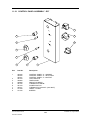
1
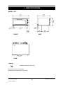
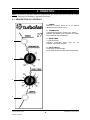
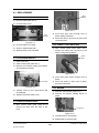
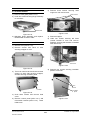
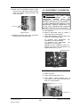
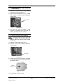
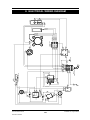
E27 CONVECTION OVEN
E27MS CONVECTION OVEN
SERVICE
MANUAL
E27 Convection Oven
Revision 3/F3563
-1-
© Moffat Ltd, August 2006
WARNING: ALL INSTALLATION AND SERVICE REPAIR WORK MUST BE CARRIED
OUT BY QUALIFIED PERSONS ONLY.
E27 Convection Oven
Revision 3/F3563
-2-
© Moffat Ltd, August 2006
CONTENTS
This manual is designed to take a more in depth look at the E27 convection oven for the purpose of
making the unit more understandable to service people.
There are settings explained in this manual that should never require to be adjusted, but for
completeness and those special cases where these settings are required to change, this manual
gives a full explanation as to how, and what effects will result.
SECTION
PAGE NO.
1.
SPECIFICATIONS......................................................................................................... 5
2.
INSTALLATION............................................................................................................. 7
3.
OPERATION .................................................................................................................. 8
3.1
3.2
4.
Description of Controls
Explanation of Control System
MAINTENANCE............................................................................................................. 10
4.1
4.2
Cleaning
Routine Procedures
5.
TROUBLE SHOOTING GUIDE..................................................................................... 11
6.
SERVICE PROCEDURES ............................................................................................. 14
6.1
6.2
6.3
6.4
Fault Diagnosis
Access
Replacement
Adjustment / Calibration
7.
ELECTRICAL SCHEMATICS ....................................................................................... 27
8.
ELECTRICAL WIRING DIAGRAMS ............................................................................. 28
9.
SPARE PARTS.............................................................................................................. 29
10.
ACCESSORIES / OPTIONS ......................................................................................... 30
IMPORTANT: MAKING ALTERATIONS MAY VOID WARRANTIES AND APPROVALS.
E27 Convection Oven
Revision 3/F3563
-3-
© Moffat Ltd, August 2006
11.
PARTS DIAGRAM ........................................................................................................ 31
11.1
11.2.1
11.3.2
11.3
12.
Main Assembly
Control Panel Assembly - E27
Control Panel Assembly - E27MS
E27MS Door Assembly
SERVICE CONTACTS.................................................................................................. 37
APPENDIX A. DOUBLE STACKING KIT .............................................................................. 39
E27 Convection Oven
Revision 3/F3563
-4-
© Moffat Ltd, August 2006
1. SPECIFICATIONS
MODEL: E27
430
725
(28.5)
1
E
1
E
45
(1.75)
791
(31.1)
77
(3.0)
(16.9)
945
(37.2)
120
236
(9.3)
(4.7)
FRONT
395
(15.6)
SIDE
1
E
PLAN
LEGEND
- Electrical connection entry point
Dimensions shown in millimetres.
Dimensions in inches shown in brackets.
E27 Convection Oven
Revision 3/F3563
-5-
© Moffat Ltd, August 2006
LOCATION
To ensure correct ventilation for the motor and
controls the following minimum installation
clearances are to be adhered to:
Top
Rear
Left-hand side
Right-hand side
200mm / 8”
25mm / 1”
25mm / 1”
25mm / 1”
OVEN INTERNAL DIMENSIONS
Width
Height
Depth
Oven Volume
695 mm / 27 3/8”
285 mm / 11 1/4”
505 mm / 19 7/8”
0.10 m³ / 3.5 ft³
OVEN RACK SIZE
Width
Depth:
660 mm / 26”
460 mm / 18”
ELECTRICAL SUPPLY
OPTIONS
SPECIFICATION
208-220V ac, 50/60Hz, 14.4A, 3.0kW @ 208V
230-240V ac, 50/60Hz, 12.5A, 3.0kW @ 240V
ELECTRICAL
PLUG
REQUIREMENTS
SPECIFICATION
Australia
3-pin 250V 15A, AS/NZ 3112
Canada
3-pin 250V 15A, NEMA 6-15
New Zealand 3-pin 250V 15A, AS/NZ 3112
United Kingdom 3-pin 250V 13A fused, BS
1363A
United States 3-pin 250V 15A, NEMA 6-15
Other Countries 3-pin 250V 13A minimum,
type to meet country
standards
E27 Convection Oven
Revision 3/F3563
-6-
© Moffat Ltd, August 2006
2. INSTALLATION
WARNING: THIS APPLIANCE MUST BE GROUNDED.
WARNING: ALL INSTALLATION AND SERVICE REPAIR WORK MUST BE CARRIED
OUT BY QUALIFIED PERSONS ONLY.
It is most important that the oven is installed
correctly and that the operation is correct
before use. Installation shall comply with local
electrical, health and safety requirements.
BEFORE
SUPPLY
CONNECTION
TO
ELECTRICAL CONNECTION
E27 convection ovens are supplied with
pre-fitted cords. Ensure unit is fitted with the
correct cord and plug for the installation.
Refer specifications section.
Should changing of the cord be necessary,
gain access to the electrical connection
terminal block, grounding lug, and strain relief
by removing the back panel (four screws).
POWER
Unpack and check unit for damage and report
any damage to the carrier and dealer. Report
any deficiencies to your dealer. Check that
the available power supply is correct to that
shown on the rating plate located on the righthand side panel.
L1
L2
Phase
Neutral
RED
BROWN
BLACK
208-220V ac, 50/60Hz, 14.4A, 3.0kW @ 208V
230-240V ac, 50/60Hz, 12.5A, 3.0kW @ 240V
Ground
BLACK
BLUE
WHITE
GREEN
GREEN/YELLOW
WARNING: THIS APPLIANCE MUST
BE GROUNDED / EARTHED
Figure 2.1
LOCATION
To ensure correct ventilation for the motor,
and
controls
the
following
minimum
installation clearances are to be adhered to:
Top
Rear
Left-hand side
Right-hand side
RATING PLATE LOCATION
The rating plate for the E27 convection oven
is located at the bottom left corner of the RH
side panel.
200mm / 8”
25mm / 1”
25mm / 1”
25mm / 1”
IMPORTANT:
THE OVEN VENT
LOCATED ON THE CABINET TOP
MUST NEVER BE OBSTRUCTED.
Position the oven in its allocated working
position. Use a spirit level to ensure the oven
is level from side to side and front to back. (If
this is not carried out, uneven cooking could
occur). The feet used with bench mounting or
provided with stands are adjustable and will
require adjusting in levelling the unit. It should
be positioned so the operating panel and oven
shelves are easily reachable for loading and
unloading.
Rating Plate
Figure 2.2
BEFORE USE
Operate the oven for about 1 hour at 200°C
(400°F) to remove any fumes or odours which
may be present.
E27 Convection Oven
Revision 3/F3563
-7-
© Moffat Ltd, August 2006
3. OPERATION
NOTE: A full user’s operation manual is supplied with the product and can be used for further
referencing of installation, operation and service.
3.1 DESCRIPTION OF CONTROLS
1. POWER
Depress to switch power on or off (switch
illuminates when power is on).
2. THERMOSTAT
Temperature range 50 - 250°C (120 - 480°F).
Indicator illuminates when elements are cycling
ON to maintain set temperature.
3. BAKE TIMER
1 Hour bake timer.
(Indicator illuminates when
reached, and buzzer sounds).
1
“time
up”
(0)
4. LIGHT SWITCH
Push switch to activate light.
(Oven light illuminates while button depressed).
2
3
4
E27 Convection Oven
Revision 3/F3563
-8-
© Moffat Ltd, August 2006
3.2
element. The control panel indicator light
above the thermostat knob cycles on and off
with the thermostat to indicate when the
element is on and the oven is heating. In the
‘Off’ position, the element relies on the
thermostatic control to prevent it switching on.
Accordingly, if the oven temperature drops
below approximately 20°C the thermostat and
element may cycle on at this setting.
EXPLANATION OF CONTROL
SYSTEM
The E27 Turbofan convection ovens feature
multi-function operator controls for which a
correct understanding of their operation is
required before carrying out any service or
fault repair work. The control device functions
are explained as follows:
The circulation fan on the E27 oven reverses
direction every 90 seconds for a 50Hz supply
(every 75 seconds for 60Hz). Prior to a
change of direction the fan motor is switched
off for 10 seconds (8½ seconds for 60Hz) to
allow the motor/fan to slow down. Cycling of
the fan motor is controlled by a continuous
cam timer with electric motor. The timer has
two cams and switches which supply power
alternately to one of two motor supply wires,
causing the motor to alternate direction.
During the fan motor slow down periods, both
cam switches are open and power is not
supplied to either of the motor supply wires.
When the oven door is opened or the power is
switched off the cams will stop. When the
oven door is closed or the power switched
back on the cam timer will resume its cycle
from the point where it stopped.
A power switch on the control panel isolates
power to all the controls of the oven. With the
power switch Off all functions of the oven are
inoperable.
NOTE: The supply voltage is fed to the input
side of the heating element power relay
whenever the electrical supply is on.
With the power switch On (illuminated) power
is directly supplied to the 60 minute bake
timer, door microswitch, and the light switch.
The light switch will turn the oven light on
when the door is closed, but only whilst the
light switch is held in.
The door microswitch on the E27 oven
controls the light, the circulation fan, and the
fan element. Hence, opening the door on the
E27 oven causes the circulation fan and fan
element to switch off, as well as causing the
oven light to come on.
The fan motor is a split phase continuous
capacitor motor with the capacitor externally
connected across the motor supply leads.
The motor also incorporates an internal
thermal trip switch for overheat protection
which is auto resetting.
The 60 minute timer is a mechanical timer and
can therefore be operated with the oven’s
power switch On or Off. However, only with
the oven’s power switch On will the switch
contacts of the 60 minute timer turn on the
time-up buzzer and illuminate the time-up
indicator on the control panel. The buzzer
and time-up indicator provide indication that
the time setting has run down to zero and at
this point will remain On continuously until the
60 minute timer has been manually set back
to the Off (vertical) position. The 60 minute
timer does not control any other part of the
oven’s operating system as this timer is
independent of the temperature control and
heating system.
The following Troubleshooting Guide (section
5) should be used to identify any incorrect
oven operation. On correct identification of
the operating fault the Troubleshooting Guide
will make reference to the corrective action
required, or refer to the Fault Diagnosis
section and/or Service section to assist in
correction of the fault.
The temperature control of these ovens is with
a capillary type thermostat which can be set to
a required cooking temperature.
The E27 has an element coiled around the
circulation fan in the rear of the oven. Power
to the element is provided via a heating power
relay located at the rear of the oven. When
the thermostat calls for heat, it energises this
relay, which switches power to the fan
E27 Convection Oven
Revision 3/F3563
-9-
© Moffat Ltd, August 2006
4. MAINTENANCE
WARNING: ALL INSTALLATION AND SERVICE REPAIR WORK MUST BE CARRIED
OUT BY QUALIFIED PERSONS ONLY.
4.1 CLEANING
OVEN SEALS
To remove, hold at their centre point and pull
forward until they unclip. Remove side seals
first, then top and bottom. The seals may be
washed in the sink, but take care not to cut or
damage them. To replace the top seal,
ensure that the lip is facing the oven opening.
The left, right and bottom seals have the lip
facing out. Fit the top and bottom seals first,
then the side seals.
WARNING: ALWAYS TURN THE
POWER SUPPLY OFF BEFORE
CLEANING.
IMPORTANT: THIS UNIT IS NOT
WATER PROOF.
DO NOT USE A WATER JET SPRAY TO
CLEAN INTERIOR OR EXTERIOR OF
THIS UNIT.
OVEN DOOR GLASS
EXTERIOR
Clean with conventional glass cleaners
Clean with a good quality stainless steel
cleaning compound. Harsh abrasive cleaners
may damage the surface.
4.2 ROUTINE PROCEDURES
INTERIOR
DOOR SEALS
Ensure that the oven chamber is cool. Do not
use wire brushes, steel wool or other abrasive
materials. Clean the oven regularly with a
good quality oven cleaner. Take care not to
damage the fan or the tube at the right side of
the oven which controls the thermostat.
Check for deterioration
12 months
ELEMENTS
Check that element resistances
12 months
are correct to their ratings (refer
6.3.9)
OVEN RACKS
To remove, slide out to the stop position, raise
the front edge up, and lift out.
SIDE RACKS
Undo the thumbscrew (anti-clockwise rotation)
securing rack to oven wall, swing rack
towards centre of oven to disengage location
pin at front of side, and pull rack forward to
remove. To replace, engage rack in rear
holes, swing towards side of oven to engage
in front hole, and replace thumbscrew.
FAN BAFFLE
To remove, loosen thumbscrews (anticlockwise rotation) at top of baffle. Lift baffle
to disengage from locating studs and thumbscrews then pull forward to remove. Replace
in reverse order.
E27 Convection Oven
Revision 3/F3563
-10-
© Moffat Ltd, August 2006
5. TROUBLE SHOOTING
WARNING: ALL INSTALLATION AND SERVICE REPAIR WORK MUST BE CARRIED
OUT BY QUALIFIED PERSONS ONLY.
FAULT
THE OVEN DOES NOT
OPERATE / START
POSSIBLE CAUSE
REMEDY
The mains isolating switch on
Turn on.
the wall, circuit breaker or fuses
are “off” at the power board.
The power switch on the oven is Depress switch. Switch will
off.
illuminate.
FAN DOESN’T OPERATE
FAN ONLY OPERATES IN
ONE DIRECTION
Incorrect electrical supply.
(Refer fault diagnosis 6.1.1)
Ensure electrical supply correct.
Power switch on unit faulty.
(Refer fault diagnosis 6.1.1)
Replace.
(Refer service section 6.3.4)
Door not closed.
Close door.
Fan obstructed.
Clear obstruction.
Door microswitch is out of
adjustment.
(Refer fault diagnosis 6.1.2)
Adjust.
(Refer service section 6.4.2)
Door microswitch faulty.
(Refer fault diagnosis 6.1.2)
Replace.
(Refer service section 6.3.2)
Fan motor faulty.
(Refer fault diagnosis 6.1.2)
Replace.
(Refer service section 6.3.11)
Motor timer faulty.
(Refer fault diagnosis 6.1.2)
Replace.
(Refer service section 6.3.12)
Motor capacitor faulty.
(Refer fault diagnosis 6.1.2)
Replace.
(Refer service section 6.3.13)
Wiring.
Check and tighten any loose
wiring.
Motor timer faulty.
(Refer fault diagnosis 6.1.2)
Replace.
(Refer service section 6.3.13)
OVEN LIGHT NOT
Blown bulb.
ILLUMINATING - DOOR OPEN
OVEN LIGHT NOT
ILLUMINATING - DOOR
CLOSED
E27 Convection Oven
Revision 3/F3563
Replace.
(Refer service section 6.3.1)
No power to light.
(Refer fault diagnosis 6.1.3)
Correct fault.
Blown bulb.
Replace.
(Refer service section 6.3.1)
Light switch faulty.
(Refer fault diagnosis 6.1.4)
Replace.
(Refer service section 6.3.4)
-11-
© Moffat Ltd, August 2006
FAULT
POSSIBLE CAUSE
REMEDY
60 MINUTE TIMER WILL NOT
TIME DOWN
Timer faulty.
Replace.
(Refer service section 6.3.6)
60 MINUTE TIMER
INACCURATE BELOW 20
MINUTES
Timer not set correctly.
For timer settings below 20
minutes, always rotate past 20
minutes, then back to desired
time.
Zero (time up) position not set
correctly.
(Refer service section 6.4.3)
Buzzer faulty.
(Refer fault diagnosis 6.1.5)
Replace.
(Refer service section 6.3.5)
Timer not switching on buzzer.
(Refer fault diagnosis 6.1.5)
Replace timer.
(Refer service section 6.3.6)
60 MINUTE TIMER NO TIME
UP INDICATOR
Indicator faulty.
(Refer fault diagnosis 6.1.6)
Replace.
(Refer service section 6.3.3)
NO HEAT - FAN ELEMENT
NOT WORKING
No power to thermostat.
(Refer fault diagnosis 6.1.7)
Identify fault and correct.
Thermostat faulty.
(Refer fault diagnosis 6.1.7)
Replace.
(Refer service section 6.3.7)
Fan element not working.
(Refer fault diagnosis 6.1.7)
Replace.
(Refer service section 6.3.9)
Heating power relay faulty.
(Refer fault diagnosis 6.1.7)
Replace.
(Refer service section 6.3.8)
Thermostat faulty.
(Refer fault diagnosis 6.1.8)
Replace.
(Refer service section 6.3.7)
Heating relay faulty.
(Refer fault diagnosis 6.1.8)
Replace.
(Refer service section 6.3.8)
Overloading of oven.
Reduce oven loading.
Electrical supply incorrect.
Check supply voltage is as per
rating plate voltage.
Fan not working.
Check fan operation.
Thermostat calibration.
(Refer fault diagnosis 6.1.9)
Correct calibration.
(Refer service section 6.4.1)
Indicator faulty.
(Refer fault diagnosis 6.1.10)
Replace.
(Refer service section 6.3.3)
60 MINUTE TIMER NO TIME
UP BUZZER
NO TEMPERATURE
CONTROL
SLOW RECOVERY
NO THERMOSTAT HEATING
INDICATOR LIGHT
E27 Convection Oven
Revision 3/F3563
-12-
© Moffat Ltd, August 2006
FAULT
DOOR DOES NOT CLOSE
DOOR SEAL LEAKS
E27 Convection Oven
Revision 3/F3563
POSSIBLE CAUSE
REMEDY
Tray in way of door.
Correctly position tray in rack.
Door seal obstruction.
Correctly install door seal.
(Refer service section 6.3.16)
Door hinges worn.
Replace.
(Refer service section 6.3.18)
Door hinge counter brackets
worn.
Replace.
(Refer service section 6.3.19)
Door seal damaged.
Replace.
(Refer service section 6.3.16)
Door seal incorrectly fitted.
Correctly install door seal.
(Refer service section 6.3.16)
-13-
© Moffat Ltd, August 2006
6. SERVICE PROCEDURES
WARNING: ENSURE POWER SUPPLY IS SWITCHED OFF BEFORE SERVICING.
WARNING: ALL INSTALLATION AND SERVICE REPAIR WORK MUST BE CARRIED
OUT BY QUALIFIED PERSONS ONLY.
SECTION
6.1
FAULT DIAGNOSIS ..............................................................................................................16
6.1.1
6.1.2
6.1.3
6.1.4
6.1.5
6.1.6
6.1.7
6.1.8
6.1.9
6.1.10
6.2
Oven Does Not Operate / Start............................................................................16
Fan Does Not Operate.........................................................................................16
Oven Light Not Illuminating—Door Open ............................................................17
Oven Light Not Illuminating—Door Closed ..........................................................17
60 Minute Timer No Time Up Buzzer ..................................................................17
60 Minute Timer No Time Up Indicator................................................................17
No Heat (Fan Element Not Working) ...................................................................17
No Temperature Control ......................................................................................18
Slow Recovery .....................................................................................................18
No Thermostat Heating Indicator.........................................................................18
ACCESS ................................................................................................................................19
6.2.1
6.2.2
6.2.3
6.2.4
6.3
PAGE NO.
Control Panel .......................................................................................................19
Service Panel (Rear Panel) .................................................................................19
Baffle ....................................................................................................................19
E27 Control Panel (Rear).....................................................................................19
REPLACEMENT....................................................................................................................20
6.3.1
6.3.2
6.3.3
6.3.4
6.3.5
6.3.6
6.3.7
6.3.8
6.3.9
6.3.10
6.3.11
6.3.12
6.3.13
6.3.14
6.3.15
6.3.16
6.3.17
6.3.18
6.3.19
Light Bulb / Glass.................................................................................................20
Door Microswitch .................................................................................................20
Indicator Neon Light.............................................................................................20
Power / Lights ......................................................................................................20
Buzzer ..................................................................................................................20
Bake Timer...........................................................................................................21
Thermostat ...........................................................................................................21
Relay ....................................................................................................................21
Element ................................................................................................................21
Fan .......................................................................................................................22
Motor ....................................................................................................................22
Fan Motor Timer ..................................................................................................22
Fan Motor Capacitor ............................................................................................22
Outer Glass ..........................................................................................................23
Inner Glass...........................................................................................................23
Door Seals ...........................................................................................................23
Door Handle .........................................................................................................23
Door Hinges .........................................................................................................24
Hinge Counter Brackets.......................................................................................24
E27 Convection Oven
Revision 3/F3563
-14-
© Moffat Ltd, August 2006
6.4
ADJUSTMENT / CALIBRATION ..........................................................................................25
6.4.1
6.4.2
6.4.3
6.4.4
Thermostat Calibration.........................................................................................25
Door Microswitch Adjustment ..............................................................................25
60 Minute Timer Zero Position Adjustment..........................................................26
Buzzer Volume Adjustment..................................................................................26
E27 Convection Oven
Revision 3/F3563
-15-
© Moffat Ltd, August 2006
6.1 FAULT DIAGNOSIS
Fan motor timer faulty
6.1.1 OVEN DOES NOT OPERATE / START
With oven switched on, and door closed,
ensure that the cams on the motor timer are
rotating.
Incorrect electrical supply
Check that the voltage across phase and
neutral (L1 and L2) terminals of terminal block
is the voltage as stated on the unit’s electrical
rating plate.
If incorrect, check electrical connection of
supply wiring and / or check electrical supply.
Motor
Cams
(Rotate one
revolution every
3 minutes)
Power switch faulty
Check if power switch latches. If the switch
does not latch, then switch is faulty—replace.
Figure 6.1.2
With switch latched, check voltage across
terminal one to terminal three or four. If there
is no voltage, check for fault in wiring.
If cams are rotating, then isolate the power
supply from the oven. Remove the bottom
wire from the left hand switch terminals.
Rotate the cams manually whilst testing for
continuity through the left hand switch. Check
that the continuity cycles as the cams are
rotated. Re-secure the left hand wire, and
then repeat test for right hand switch.
Check voltage across terminal two to terminal
three or four. If there is no voltage, then
switch is faulty—replace.
NOTE:
When power switch is latched, it
should
illuminate
if
operating
correctly.
When operating, 50Hz models should cycle
the power for approximately 80 seconds
through each switch, with a 10 second delay
between each cycle.
6.1.2 FAN DOESN’T OPERATE
On 60Hz models the power should cycle
for approximately 65 seconds through each
switch, with an 8 second delay between each
cycle.
Microswitch out of adjustment
Open oven door and manually depress door
microswitch actuator at top right of oven. If
this activates the fan, then the microswitch
actuator arm inside control cavity requires
adjustment.
If there is no continuity, or the continuity does
not cycle correctly then timer is faulty replace.
Microswitch faulty
Fan motor capacitor faulty
Check voltage from microswitch terminals to
neutral.
Ensure that oven is isolated from the power
supply. Disconnect all wires from the motor
terminal block, except for the two capacitor
wires. Briefly short across the capacitor
terminals, to ensure that it is fully discharged.
With the door closed there should be power to
the com terminal and the n.o. terminal.
With the door open there should be power to
the com terminal and the n.c. terminal.
Using a multimeter, measure the resistance
across capacitor terminals.
If not, microswitch is faulty—replace.
Microswitch
n.c.
Capacitor
Terminals
com
n.o.
Figure 6.1.1
Figure 6.1.3
E27 Convection Oven
Revision 3/F3563
-16-
© Moffat Ltd, August 2006
The resistance should start low and quickly
increase to infinity within 5-10 seconds. If the
resistance does not increase at all, then the
capacitor is shorted - replace. If the capacitor
is infinite resistance straight away then it is
open-circuit - replace. If the resistance never
goes very high then the capacitor is leaky replace.
bottom terminal. If there is no voltage, then
replace the switch.
If voltage is correct, then check wiring to light.
NOTE: Alternately, perform a continuity test
across the terminals with the light
switch depressed.
6.1.5 60 MINUTE TIMER NO TIME UP
BUZZER
Fan motor faulty
At rear of oven, check that there is supply
voltage from neutral to both of the phase
terminals on the motor terminal block.
Buzzer faulty
With timer in ‘zero’ position, check the buzzer
at bottom of control panel (inside) for voltage
across terminals. If voltage is correct then
buzzer is faulty—replace.
Neutral
If there is no voltage, then check wiring.
Phase
Buzzer Terminals
Phase
Figure 6.1.4
Buzzer
If the voltage to the motor terminal block is
correct, and the capacitor is not faulty, then
check the oven fan for free rotation. Remove
any obstruction.
Figure 6.1.5
Timer not switching on buzzer
If fan is free to spin and the voltage supply is
correct, then the motor is faulty—replace.
With timer in zero position, check voltage to
terminal 1 and terminal 2 of timer. If there is
no voltage at terminal 1 then check wiring.
6.1.3 OVEN LIGHT NOT ILLUMINATING—
DOOR OPEN
If no voltage at terminal 2 then timer is
faulty—replace.
No power to light
NOTE: Buzzer and time up indicator will continue until the timer manually switched off (to
vertical position).
Check the supply voltage across lamp
housing terminals at rear of oven. If the
voltage is correct, replace the bulb (if faulty).
If the bulb is OK, check lamp housing.
Replace if faulty.
6.1.6 60 MINUTE TIMER NO TIME UP
INDICATOR
If there is no voltage, check voltage across
micro-switch terminals to neutral.
Indicator faulty
With the door closed there should be power to
the com terminal and the n.o. terminal.
With the timer in the zero position, check for
voltage across the indicator light. If correct,
then the indicator light is faulty—replace.
With the door open there should be power to
the com terminal and the n.c. terminal.
If there is no voltage then check wiring.
If not, microswitch is faulty—replace.
6.1.7 NO HEAT
6.1.4 OVEN LIGHT NOT ILLUMINATING—
DOOR CLOSED
No power to thermostat
With door closed, check voltage to terminal P
of the oven thermostat. If there is no voltage
then check voltage to terminal NO of door
microswitch. If there is no voltage then refer
6.1.2, microswitch out of adjustment / faulty.
If there is voltage then check wiring to the
thermostat.
Light switch faulty
Check voltage to the top terminal of the
switch. If there is no voltage, then check
wiring.
With switch depressed, check voltage at
E27 Convection Oven
Revision 3/F3563
-17-
© Moffat Ltd, August 2006
Thermostat faulty
6.1.9 SLOW RECOVERY
Set thermostat to 200°C or 400°F. Check the
voltage out of terminal 1 on the thermostat. If
there is no voltage (and there is voltage at
terminal P) then the thermostat is faulty—
replace.
Thermostat out of calibration
Place an accurate digital thermometer probe
in centre of oven. Set thermostat to 180°C or
355°F. Close the oven door and allow oven
thermostat to cycle on and off twice. Record
oven centre temperature for the next
thermostat on and off cycle. The thermostat
should cycle on and off between 165°C and
195°C or 330°F and 385°F when set to the
above temperature. If oven temperature is
outside these ranges, then the thermostat
requires recalibration.
If the voltage is correct and the heating light is
on then check all wiring to elements.
Fan element faulty (blown)
With the thermostat on and heating check
voltage across fan element terminals at rear
of oven. If the voltage is correct then check
the current draw of element. If there is no
current draw then element is faulty—replace.
NOTE: Thermostat cycling span should be
±15°C or 27°F
NOTE: Correct fan element current draw:
E27 208-220 V: 13.4A ± 1.5A
E27 230-240 V: 12.1A ± 1.5A
6.1.10 NO THERMOSTAT HEATING
INDICATOR
Indicator faulty
With the thermostat on and heating, check the
voltage across the indicator terminals. If the
voltage is correct then the indicator is faulty—
replace.
Element
Wires
If there is no voltage then check wiring.
Figure 6.3.10
Heating power relay faulty
Set thermostat to 200°C or 400°F. With door
closed, check voltage from terminal B to
terminal A of heating relay. If no voltage
check wiring. Check voltage to terminal 6. If
voltage at terminal 6 but no voltage at terminal
4 then the relay is faulty - replace.
6.1.8 NO TEMPERATURE CONTROL
Thermostat faulty
With thermostat in ‘off’ position (knob vertical),
slowly turn thermostat up until heating
indicator just comes on. Wait for heating
indicator to cycle off. If indicator has not
cycled off after 10 minutes then thermostat is
faulty—replace.
NOTE: E27 thermostat may cycle on and off
with the knob set to the ‘off’ position if the
oven temperature is below 20°C.
Heating relay faulty
With power switch off on control panel, check
for voltage at terminal 4 of heating relay. If
there is voltage then the heating relay is
faulty—replace.
E27 Convection Oven
Revision 3/F3563
-18-
© Moffat Ltd, August 2006
6.2 ACCESS
6.2.4 E27 CONTROL PANEL—REAR
6.2.1 CONTROL PANEL
Power Switch
1) Undo one screw at bottom of control
panel.
Heating Indicator
Thermostat
Bake Time Up
Indicator
One Screw
Figure 6.2.1
60 min Bake Timer
2) Pull out bottom of control panel and drop
down to disengage tabs at top of control
panel.
Light Switch
6.2.2 SERVICE (REAR) PANEL
1) Undo the four screws holding the panel.
Buzzer
Figure 6.2.4
Four
Screws
Figure 6.2.2
2) Remove panel.
6.2.3 BAFFLE
1) Remove all trays and racks.
2) Loosen two thumb screws (top).
Thumb
screws
Figure 6.2.3
3) Lift baffle to disengage from locating studs
and thumbscrews, and remove baffle.
E27 Convection Oven
Revision 3/F3563
-19-
© Moffat Ltd, August 2006
6.3 REPLACEMENT
Neon
Wires
6.3.1 LIGHT BULB / GLASS
1) Remove baffle (refer 6.2.3).
2) Unscrew lamp cover.
Figure 6.3.3
2) From back push neon through front of
panel rotating clockwise.
Lamp
Cover
3) Push new neon in from front of panel, and
reconnect wires.
Figure 6.3.1
6.3.4 POWER / LIGHT SWITCHES
3) Unscrew bulb out of fitting.
4) Screw in replacement bulb.
1) With control panel open (refer 6.2.1)
remove the wires from the back of the
switch, noting their positions.
5) Replace lamp cover and baffle.
Switch
Wires
6.3.2 DOOR MICROSWITCH
1) Open oven door.
2) Open control panel (refer 6.2.1).
3) Remove two screws holding microswitch
and insulator to bracket.
Figure 6.3.4
2) From back push switch through front of
panel.
Two Screws
3) Push new switch in from front of panel,
and reconnect wires.
Figure 6.3.2
6.3.5 BUZZER
4) Transfer wires to new micro-switch and
re-assemble.
1) Remove control panel (refer 6.2.1).
2) Remove two screws holding buzzer to
panel.
5) Adjust microswitch (refer 6.4.2).
6.3.3 INDICATOR NEON LIGHT
1) With control panel open (refer 6.2.1)
remove the wires from the back of the
neon.
Two Screws
Figure 6.3.5
4) Transfer wires to new buzzer.
5) Reassemble in reverse order.
E27 Convection Oven
Revision 3/F3563
-20-
© Moffat Ltd, August 2006
6.3.6 BAKE TIMER
6.3.8 RELAY
1) Remove bake timer knob by pulling it
firmly away from control panel.
1) Remove service panel (refer 6.2.2).
2) Undo two screws securing relay to oven.
2) Open control panel (refer 6.2.1) and undo
two screws securing timer.
Two Screws
Two
Screws
Figure 6.3.9
3) Transfer wires to new relay, and secure to
oven with screws.
Figure 6.3.6
3) Transfer wires to new timer.
4) Withdraw old timer and insert new timer,
securing with screws.
6.3.9 ELEMENT
5) Replace knob.
1) With service panel and baffle removed
(refer 6.2.2 and 6.2.3) remove the wires
from the rear of the element.
6.3.7 THERMOSTAT
1) Pull knob off front of thermostat
2) Open control panel (refer 6.2.1) and undo
two screws securing thermostat.
Two Screws
Element
Wires
Figure 6.3.10
2) Unscrew the element from inside the
oven.
Figure 6.3.7
3) Transfer wires to new thermostat.
4) Remove service panel (refer 6.2.2) and
from inside of oven loosen two screws
holding thermostat phial bracket.
3 Screws
Figure 6.3.11
3) Pull element carefully to remove.
Two
Screws
4) Replace and re-assemble in reverse
order.
Figure 6.3.8
Element Ratings (±5%)
5) Withdraw old thermostat phial through
rear of oven.
208-220V Fan Element
15.5 ohms
6) Insert new thermostat.
230-240V Fan Element
20.5 ohms
7) Re-assemble in reverse order.
E27 Convection Oven
Revision 3/F3563
-21-
© Moffat Ltd, August 2006
4) Replace and re-assemble in reverse order.
6.3.10 FAN
5) Ensure wire connections are correct (fig
6.3.13)
1) With baffle removed (refer 6.2.3) loosen
the grub screw on the hub of the fan.
6.3.12 MOTOR DIRECTION TIMER
1) Open control panel (refer 6.2.1).
Grub Screw
2) Remove wires from the timer, noting their
positions, and the wire to the timer motor
from the control panel.
3) Remove the four screws securing the
timer to the timer mounting bracket.
Figure 6.3.12
2) Withdraw the fan from the shaft.
3) Replace and re-assemble in reverse
order.
Four
Screws
NOTE: Ensure Teflon sealing washer is in
position on fan shaft between fan and
oven rear.
6.3.11 MOTOR
1) Remove fan (refer 6.3.10), and remove
service panel (refer 6.2.2).
2) Remove the brown, blue and black wires
that go to the motor from the motor
terminal block.
Figure 6.3.15
4) Replace the timer and reassemble in
reverse order.
Brown
Blue
White
6.3.13 MOTOR CAPACITOR
1) Remove service panel (refer 6.2.2).
Black
Black
2) Undo the nut securing capacitor to oven.
Figure 6.3.13
Nut
3) Undo the four screws holding the motor
and bracket in place and remove the
motor.
Screws (x4)
Figure 6.3.16
3) Remove the capacitor wires from the
motor terminal block.
4) Replace with new capacitor, and reassemble in reverse order.
Figure 6.3.14
E27 Convection Oven
Revision 3/F3563
-22-
© Moffat Ltd, August 2006
3) Uncrimp the retaining lugs of the window
spacer and remove the spacer and glass.
6.3.14 OUTER GLASS (E27)
1) Open the oven door.
2) Lock hinges into position by rotating the
hinge locking clip over the hinge locking
notch.
Hinge Locking
Notch
Retaining
Lugs
Figure 6.3.20
4) To replace, ensure the silicone rubber seal
has not been displaced. Clean the glass
and refit it. Place the window spacer in
position and crimp the retaining lugs over
to hold the glass in place. Refit outer
glass as above.
Hinge Locking Clip
Figure 6.3.17
3) Lift door away from the oven and place on
a flat surface.
4) Undo three screws and remove the trim
from the bottom of the door. Carefully
withdraw the glass.
6.3.16 DOOR SEALS
1) Open oven door.
2) To remove, hold at their centre point and
pull forward until they unclip
3) Refit new seals.
Note: Fit top and bottom seals first, with
open
side
of
seal
facing
downwards. Fit side seals with
open side facing outwards.
Three Screws
Figure 6.3.18
5) To replace, ensure that the two silicone
rubber seals are in place on the left hand
and right hand side of the door frame.
Clean the inside of the glass and refit it,
ensuring that the silicone rubber seals
cover the outer edges of the glass. Refit
the bottom trim, and fit the door to the
oven.
6.3.17 DOOR HANDLE (E27)
1) Remove the door (refer 6.3.14).
2) Undo four screws and remove the top trim
and handle assembly, taking care not to
dislodge the outer glass.
3) Undo two bolts securing handle to top
trim. Replace handle and reassemble in
reverse order.
6.3.15 INNER GLASS (E27)
1) Remove the outer glass (refer 6.3.14).
2) Undo four screws and remove the top trim
and handle assembly.
Two Bolts
Figure 6.3.21
Four Screws
Figure 6.3.19
E27 Convection Oven
Revision 3/F3563
-23-
© Moffat Ltd, August 2006
6) Remove three screws securing lintel
support to oven and remove.
6.3.18 DOOR HINGES
1) Remove outer glass (refer 6.3.14).
Three screws
2) Undo two screws securing hinge assembly
to oven door.
Two Screws
Figure 6.3.25
Figure 6.3.22
3) Withdraw hinge assembly and replace.
Reassemble in reverse order.
7) Remove wrapper.
8) Undo two screws securing left hand
counter bracket to oven and remove.
Replace, ensuring that bracket is installed
with roller to top.
6.3.19 HINGE COUNTER BRACKETS
1) Remove door (refer 6.3.14).
2) Remove screws from back of oven
securing wrapper to oven.
Two screws
Figure 6.3.26
Figure 6.3.23
9) Remove two screws securing insulation
panel to oven liner.
3) Turn oven onto its back and remove three
screws at each side securing wrapper,
and two securing insulation panel.
Two
Screws
8 screws
Insulation
panel
Figure 6.3.24
4) Undo three screws and remove lintel
cover.
5) Remove control panel (refer 6.2.1) and
microswitch bracket (refer 6.3.2). Place
inside oven.
E27 Convection Oven
Revision 3/F3563
Figure 6.3.27
-24-
© Moffat Ltd, August 2006
10) Prise open the insulation panel to allow
access to the right hand counter bracket.
Undo two screws securing bracket, and
remove bracket.
6.4 ADJUSTMENT / CALIBRATION
6.4.1 THERMOSTAT CALIBRATION
IMPORTANT:
IF
THE
OVEN
TEMPERATURE
NEEDS
TO
BE
INCREASED,
ENSURE
THAT
THE
THERMOSTAT IS IN THE ‘OFF’ POSITION
BEFORE CARRYING OUT ADJUSTMENT.
IF OVEN TEMPERATURE NEEDS TO BE
DECREASED, ENSURE THERMOSTAT IS
IN THE ‘MAX’ TEMPERATURE POSITION
BEFORE CARRYING OUT ADJUSTMENT.
Two screws
1) Turn off power.
Figure 6.3.28
2) Remove thermostat knob by pulling it
firmly away from control panel.
11) Replace, ensuring roller to top of bracket.
Re-assemble in reverse order.
3) Adjust the calibration screw located in the
centre of the thermostat shaft.
To increase oven temperature, turn
calibration screw anticlockwise.
To decrease oven temperature, turn
calibration screw clockwise.
Adjustment of the calibration screw by 1°
angular will alter oven temperature by
approximately 0.8°C (1.5°F).
Calibration Screw
Figure 6.4.1
6.4.2 DOOR MICROSWITCH ADJUSTMENT
1) Open oven door.
2) Open control panel (refer 6.2.1).
3) With fingers, bend actuator arm of
microswitch so that switch operates when
door is in closed position.
Actuator Arm
Figure 6.4.2
E27 Convection Oven
Revision 3/F3563
-25-
© Moffat Ltd, August 2006
6.4.3 60 MINUTE TIMER ZERO POSITION
ADJUSTMENT
1) Remove 60 minute timer knob by pulling it
firmly away from control panel.
2) Open control panel (refer 6.2.1). Loosen
two screws on control panel holding 60
minute timer.
Two Screws
Figure 6.4.3
3) The timer can now be rotated a small
amount as required to ensure that the
buzzer sounds at the zero position.
6.4.4 BUZZER VOLUME ADJUSTMENT
NOTE: The buzzer volume is set to full at the
factory. Should the volume need to be
reduced then the following steps should
be followed.
1) Remove control panel (refer 6.2.1).
2) Remove two screws holding buzzer to
control panel.
Two Screws
Figure 6.4.4
3) Adjust volume screw on buzzer, clockwise
to increase volume, and anti-clockwise to
decrease volume.
Volume
Adjustment
Figure 6.4.5
4) Reassemble in reverse order.
E27 Convection Oven
Revision 3/F3563
-26-
© Moffat Ltd, August 2006
E27 Convection Oven
Revision 3/F3563
Ø
-27-
E
L2
N
1
6
FAN
ELEMENT
2.8kW
POWER
RELAY
L1
4 A
B
1
P
4
3
HEATING
OVEN
T/STAT
2
1
POWER
SWITCH
M
C
3uF
No Nc No Nc
C
M
FAN
MOTOR
MOTOR
TIMER
No Nc
C
LIGHT
DOOR
SWITCH
TIME
UP
LIGHT
SWITCH
2
3
1
B
5
1Hr
TIMER
BUZZER
6
4
7. ELECTRICAL CIRCUIT SCHEMATIC
© Moffat Ltd, August 2006
E27 Convection Oven
Revision 3/F3563
-28-
3
2
20
1
P
4
3 2
11
1
3
1
2
12
TIMER
19
HEAT
21
TIME UP
T/STAT
20
13
14
6
BUZZER
19
POWER
12
LIGHTS
15
14
5
3
1
1
4
2
18
7
Nc
No
COM
30
4
NC
17
COM
16
6
30
18
1
L1
8
MAINS
TERMINAL BLOCK
MICROSWITCH
NO
MOTOR TIMER
5
22
L2
23
26
G
25
27
EARTH STUD
29
8
22
6
B
N
POWER
RELAY
15
27
4
A
17
16
23
24
9
3
BROWN
WHITE
BLUE
BLACK
BLACK
FAN MOTOR
28
CONNECTOR
BLOCK
10
CAPACITOR
WHITE
BLACK
2
11
10
28
26
ELEMENT
25
9
8. ELECTRICAL WIRING DIAGRAM
© Moffat Ltd, August 2006
BROWN
BLUE
BLACK
9. SPARE PARTS
PART NO
DESCRIPTION
CONTROLS
021473
023211
021472
020823
020849
011760
011794
021474
024505
003004
003002
013520
013521
SWITCH - POWER
THERMOSTAT
KNOB - THERMOSTAT
KNOB - BAKE TIMER
NEON INDICATOR
BAKE TIMER
BUZZER
LIGHT SWITCH
RELAY
MICROSWITCH
OVEN LAMP GLASS
OVEN LAMP ASSEMBLY
OVEN LAMP - 240V 40W MINIATURE EDISON SCREW
MOTOR & ELEMENTS
024410
024409
024431
024432
024503
024567
024433
021698
OVEN FAN ELEMENT (2800W) - 230-240V
OVEN FAN ELEMENT (2800W) - 208-220V
FAN MOTOR
CAPACITOR 3µF
MOTOR TIMER 208-220V
MOTOR TIMER 220-240V
FAN
BAFFLE SECURING SCREW
DOOR
SA1548
SA1768
024405
024404
021468
026498
024377
024378
024378
023218
COMPLETE DOOR ASSEMBLY (E27)
COMPLETE DOOR ASSEMBLY (E27MS)
OVEN DOOR SEAL ASSEMBLY SIDE
OVEN DOOR SEAL ASSEMBLY TOP/BOTTOM
HANDLE (E27)
HANDLE (E27MS)
DOOR OUTER GLASS (E27)
DOOR INNER GLASS (E27)
DOOR INNER AND OUTER GLASS (E27MS)
DOOR HINGE
RACKS
024406
024407
023068
024408
025349
E27 Convection Oven
Revision 3/F3563
OVEN SIDE RACK LH
OVEN SIDE RACK RH
SIDE RACK SCREW
WIRE OVEN RACK (NORTH AMERICAN MODELS)
WIRE OVEN RACK (ALL OTHER MODELS)
-29-
© Moffat Ltd, August 2006
10. ACCESSORIES
100 MM (FOUR INCH) FOOT OPTION
(PART NO 13048)
OVEN RACKS (PART NO 24408)
25 MM (ONE INCH) FOOT OPTION (PART
NO 13908)
A28 STAINLESS STEEL STAND
DOUBLE STACKING KIT (PART NO 24419)
E27 Convection Oven
Revision 3/F3563
-30-
© Moffat Ltd, August 2006
11. PARTS DIAGRAMS
11.1 MAIN ASSEMBLY
2
3
53
54
51
55
52
4
50
49
43
5
48
6
11
10
9
8
1
7
12
47
46
13
45
9
44
5
10
42
43
42
39
41
40
39
14
38
15
16
16
37
15
17
36
18
35
19
20
21
30
23
22
E27 Convection Oven
Revision 3/F3563
23
25
26
27
21
28
31
32
33
34
29
24
-31-
© Moffat Ltd, August 2006
Pos
Part No.
Description
1
2
3
4
5
6
7
004914
024393
024381
004913
024405
023219
024410
024409
024433
024398
024507
014031
024526
021698
017770
024406
023068
024408
025349
024407
024413
021468
024394
024477
024377
004919
024378
024392
024414
004918
023218
SA1550
SA1549
SA1551
024394
013908
024396
024503
024567
024504
017185
010162
017453
012206
019213
018251
002138
002441
013586
019238
024505
024395
024404
024379
021637
021638
044210
OVEN – ENAMELLED
WRAPPER
LINTEL SUPPORT
LINTEL – ENAMELLED
SIDE SEAL ASSEMBLY
HINGE COUNTER BRACKET
OVEN ELEMENT 2800W – 240V
OVEN ELEMENT 2800W – 208V
OVEN FAN
BAFFLE BRACKET TOP
BAFFLE BRACKET BOTTOM
STANDOFF
BAFFLE
BAFFLE SCREW
PHIAL GUARD
LEFT HAND SIDE RACK
SIDE RACK SCREW
OVEN RACK (NORTH AMERICAN MODEL)
OVEN RACK (ALL OTHER MODEL)
RIGHT HAND SIDE RACK
TOP TRIM (Refer Section 11.3 for E27MS Door Assembly)
DOOR HANDLE (Refer Section 11.3 for E27MS Door Assembly)
HANDLE STIFFENER (Refer Section 11.3 for E27MS Door Assembly)
OUTER GLASS SEAL (Refer Section 11.3 for E27MS Door Assembly)
DOOR OUTER GLASS (Refer Section 11.3 for E27MS Door Assembly)
GLASS CLAMP ANGLE (Refer Section 11.3 for E27MS Door Assembly)
DOOR INNER GLASS (Refer Section 11.3 for E27MS Door Assembly)
INNER GLASS SEAL (Refer Section 11.3 for E27MS Door Assembly)
BOTTOM TRIM (Refer Section 11.3 for E27MS Door Assembly)
DOOR INNER PANEL (Refer Section 11.3 for E27MS Door Assembly)
HINGE
CONTROL PANEL ASSEMBLY BAKBAR (REFER SECTION 11.2)
CONTROL PANEL ASSEMBLY BLUE SEAL (REFER SECTION 11.2)
CONTROL PANEL ASSEMBLY MOFFAT (REFER SECTION 11.2)
OVEN BODY
FOOT ASSEMBLY
INSULATION PANEL
MOTOR TIMER 208-220V
MOTOR TIMER 220-240V
MOTOR TIMER MOUNTING BRACKET
CORDSET 15A – NZ/AUST
POWERFLEX CORD 15A – EXPORT
CORDSET 13A FUSED – UK
CORDSET 15A – USA/CANADA
SNAP BUSH 32mm
CABLE ENTRY BRACKET
CABLE CLAMP
INSULATOR
TERMINAL BLOCK
SNAP BUSH 26mm
RELAY 30A
FOOT CHANNEL
OVEN TOP/BOTTOM SEAL ASSEMBLY
COVER PANEL
MICROSWITCH BUTTON
PIN CIRCLIP
SPIRE CLIP
8
9
10
11
12
13
14
15
16
16
17
18
19
20
21
22
23
24
25
26
27
28
29
30
31
32
33
34
35
36
37
38
39
40
41
42
43
44
45
46
E27 Convection Oven
Revision 3/F3563
-32-
© Moffat Ltd, August 2006
47
48
49
50
51
52
53
54
55
013610
003016
013520
003434
013521
003002
024431
024478
024432
003004
013977
023093
024399
E27 Convection Oven
Revision 3/F3563
DOOR BUSH
MOTOR MOUNTING PLATE
OVEN LAMP ASSEMBLY
SILK GASKET
LAMP 40W
LIGHT GLASS
MOTOR
MOTOR SHAFT SEAL
CAPACITOR 3µF
MICROSWITCH
INSULATOR
MICROSWITCH MOUNTING BRACKET
VENT TUBE
-33-
© Moffat Ltd, August 2006
11.2.1 CONTROL PANEL ASSEMBLY - E27
7
6
8
4
9
5
4
3
2
1
Pos
Part No.
Description
1
004916
004915
004917
021474
020823
020849
021472
021473
023211
011760
011794
CONTROL PANEL °C – BAKBAR
CONTROL PANEL °C – BLUE SEAL
CONTROL PANEL °F – MOFFAT
LIGHT SWITCH
TIMER KNOB
INDICATOR NEON
THERMOSTAT KNOB
POWER SWITCH
THERMOSTAT 50-250°C (120-480°F)
TIMER – 60 MIN
BUZZER
2
3
4
5
6
7
8
9
E27 Convection Oven
Revision 3/F3563
-34-
© Moffat Ltd, August 2006
11.2.2 CONTROL PANEL ASSEMBLY - E27MS
Pos
Part No.
Description
1
2
3
4
6
7
9
10
11
14
026487
021473
020849
023211
021472
011760
020823
021474
011794
026613
026496
CONTROL PANEL
POWER SWITCH
INDICATOR NEON
THERMOSTAT
KNOB - THERMOSTAT
1 HOUR TIMER
KNOB - TIMER
LIGHT SWITCH
BUZZER
OVERLAY - BLUE SEAL
OVERLAY - MOFFAT
E27 Convection Oven
Revision 3/F3563
-35-
© Moffat Ltd, August 2006
11.3 E27MS DOOR ASSEMBLY
Pos
Part No.
Description
1
2
3
4
5
6
7
8
005038
023218
026485
026579
026498
024378
024392
026492
DOOR INNER WA
HINGE
DOOR OUTER PANEL
HANDLE STIFFENER
DOOR HANDLE PLATED
DOOR INNER GLASS
INNER GLASS SEAL
GLASS CLAMP ANGLE
E27 Convection Oven
Revision 3/F3563
-36-
© Moffat Ltd, August 2006
11. SERVICE CONTACTS
AUSTRALIA
VICTORIA - MOFFAT PTY
HEAD OFFICE AND MAIN WAREHOUSE
740 Springvale Road
Mulgrave VIC 3170
Spare Parts Department
NEW SOUTH WALES - MOFFAT PTY
Unit 3/142 James Ruse Drive
Rosehill NSW 2142
Spare Parts
Tel (03) 9518 3888
Fax (03) 9518 3838
Free Call 1800 337 963
Fax (03) 9518 3895
Tel (02) 8833 4111
Free Call 1800 337 963
Fax (03) 9518 3895
QUEENSLAND - MOFFAT PTY
30 Prosperity Place
Geebung QLD 4034
Spare Parts
Tel (07) 3630 8600
Free Call 1800 337 963
Fax (03) 9518 3895
SOUTH AUSTRALIA - MOFFAT PTY
28 Greenhill Rd
Wayville SA 5034
Spare Parts
Tel (08) 8274 2116
Free Call 1800 337 963
Fax (03) 9518 3895
WESTERN AUSTRALIA - MOFFAT PTY
PO Box 689
Joondalup Business Centre WA 6027
Spare Parts
Tel (08) 9305 8855
Free Call 1800 337 963
Fax (03) 9518 3895
NATIONAL COVERAGE FOR 24 HOUR SERVICE OR MAINTENANCE DIAL
FREE CALL 1800 622 216 (AUSTRALIA ONLY)
CANADA
SERVE CANADA
22 Ashwarren Rd
Downview
Ontario M3J1Z5
Tel 416-631-0601
Fax 416-631-0315
NEW ZEALAND
CHRISTCHURCH - MOFFAT LTD
16 Osborne St
PO Box 10-001
Christchurch
Spare Parts
Tel (03) 389 1007
Fax (03) 389 1276
Free Call 0800 MOFFAT
(0800 6633 28)
Fax (03) 381 3616
AUCKLAND - MOFFAT LTD
4 Waipuna Road
Mt Wellington
Auckland
Spare Parts
E27 Convection Oven
Revision 3/F3563
Tel (09) 574 3150
Fax (09) 574 3159
Free Call 0800 MOFFAT
(0800 66 33 28)
-37-
© Moffat Ltd, August 2006
UNITED KINGDOM
BLUESEAL LTD
Units 6-7 Mount St Business Park
Mount St
Birmingham B7 5QU
England
Tel 0121-327 5575
Fax 0121-327 9711
UNITED STATES OF AMERICA
MOFFAT INC.
3765 Champion Blvd
Winston-Salem
NC27115
Tel 1-800-551 8795
Fax 336 661 9546
NATIONAL COVERAGE FOR SERVICE OR MAINTENANCE DIAL
FREE CALL 1800 551 8795 (USA ONLY)
E27 Convection Oven
Revision 3/F3563
-38-
© Moffat Ltd, August 2006
APPENDIX A. DOUBLE STACKING KIT (24419)
Kit Includes:
1
1
1
1
2
1
25
2
2
x
x
x
x
x
x
x
x
x
Part No
Vent Duct
Vent Pipe
Saddle Clamp
Double Stack Front
Double Stack Side
Double Stack Rear
3
/8" x 8A Pozi Pan Hd Screw
½” x 8 Phillips Head Black Screw
Black Fibre Washer
Assembly Instructions:
24306
24307
10023
04921
24509
24510
41045
41046
45605
(THE ELECTRICAL SUPPLY MUST BE DISCONNECTED)
A.
Bottom Unit (Refer figure 1)
1.
Position vent duct on bottom unit over oven vent. Temporarily locate double stack rear in
correct position on top of bottom unit. Centrally locate the vent duct in the cut-out. Check that
the oven vent is covered and mark the
five hole positions (two down each side
Double Stack Rear
of the flue duct and one at front) on the
Remove Lintel
oven wrapper.
2.
Drill five ø3.5mm holes in the oven
wrapper where marked.
3.
Secure the vent duct to the wrapper
with five 3/8" x 8A Pozi screws into
these holes.
4.
Undo the three screws securing the top
lintel to the bottom oven, and remove
the lintel. Remove the four screws
from the top rear of the oven wrapper.
B.
Top Unit
1.
Figure A.1
Remove all trays and racks from oven.
Tip oven upside down and remove the feet screwed into the base.
2.
Remove the six screws (three each side) securing the oven wrapper to the sides of the oven.
Position the double stack sides flush with the sides and front of the oven, and secure each
with three screws.
3.
Remove the three screws along the front bottom edge of the oven. Position the double stack
front over these three screw holes. Flush the ends of the double stack front with the sides of
the unit and secure to the double stack sides using the two black screws (with
fibre washers). Secure to bottom of oven with three screws.
4.
Secure the double stack rear to the double stack sides with two screws.
E27 Convection Oven
Revision 3/F3563
-39-
© Moffat Ltd, August 2006
C.
Stacking the Ovens (Refer figure A.2)
1.
With two persons, lift the top oven onto the bottom oven and position slightly forward so that
the double stack front engages with the lintel support on the bottom oven, then slide the top
oven back until the double stack rear locates over the bottom oven.
2.
Secure double stack rear to bottom unit with four screws. Secure the double stack front to the
lintel support of the bottom unit with three screws.
3.
Remove the rear cover panel from the top unit. Fit the vent pipe to the vent duct then
secure pipe to the rear panel of the top unit using the saddle clamp and two screws.
4.
Using pliers or similar, knock out the notches at the top and bottom of the rear cover panel
that allow for the vent pipe. Refit the rear cover panel to the top unit.
Figure A.2
E27 Convection Oven
Revision 3/F3563
-40-
© Moffat Ltd, August 2006
E27 Convection Oven
Revision 3/F3563
-41-
© Moffat Ltd, August 2006