1
Agilent VEE Pro
VEE Pro User’s Guide
Agilent Technologies
Notices
© Agilent Technologies, Inc. 2003
Warranty
No part of this manual may be reproduced in
any form or by any means (including electronic storage and retrieval or translation
into a foreign language) without prior agreement and written consent from Agilent
Technologies, Inc. as governed by United
States and international copyright laws.
The material contained in this document is provided “as is,” and is subject to being changed, without notice,
in future editions. Further, to the maximum extent permitted by applicable
law, Agilent disclaims all warranties,
either express or implied, with regard
to this manual and any information
contained herein, including but not
limited to the implied warranties of
merchantability and fitness for a particular purpose. Agilent shall not be
liable for errors or for incidental or
consequential damages in connection with the furnishing, use, or performance of this document or of any
information contained herein. Should
Agilent and the user have a separate
written agreement with warranty
terms covering the material in this
document that conflict with these
terms, the warranty terms in the separate agreement shall control.
Manual Part Number
E2011-90011
Edition
Version 7.0
Eighth edition, February 2004
Printed in USA
Agilent Technologies, Inc.
815 14 Street SW
Loveland, CO 80537USA
Technology Licenses
The hardware and/or software described in
this document are furnished under a license
and may be used or copied only in accordance with the terms of such license.
Restricted Rights Legend
If software is for use in the performance of a
U.S. Government prime contract or subcontract, Software is delivered and licensed as
“Commercial computer software” as
defined in DFAR 252.227-7014 (June 1995),
or as a “commercial item” as defined in FAR
2.101(a) or as “Restricted computer software” as defined in FAR 52.227-19 (June
1987) or any equivalent agency regulation or
contract clause. Use, duplication or disclosure of Software is subject to Agilent Technologies’ standard commercial license
terms, and non-DOD Departments and
Agencies of the U.S. Government will
receive no greater than Restricted Rights as
defined in FAR 52.227-19(c)(1-2) (June
2
1987). U.S. Government users will receive
no greater than Limited Rights as defined in
FAR 52.227-14 (June 1987) or DFAR
252.227-7015 (b)(2) (November 1995), as
applicable in any technical data.
Safety Notices
CAUTION
A CAUTION notice denotes a hazard. It calls attention to an operating procedure, practice, or the like
that, if not correctly performed or
adhered to, could result in damage
to the product or loss of important
data. Do not proceed beyond a
CAUTION notice until the indicated
conditions are fully understood and
met.
WA R N I N G
A WARNING notice denotes a
hazard. It calls attention to an
operating procedure, practice, or
the like that, if not correctly performed or adhered to, could result
in personal injury or death. Do not
proceed beyond a WARNING
notice until the indicated conditions are fully understood and
met.
VEE User’s Guide
VEE Pro User’s Guide
VEE Pro User’s Guide
Conventions Used in This Manual 4
VEE User’s Guide
3
VEE Pro User’s Guide
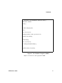
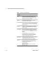
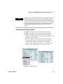
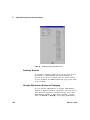
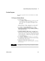
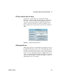
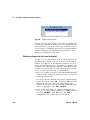
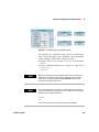
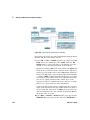
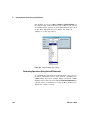
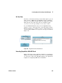
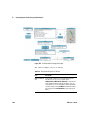
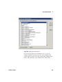
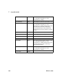
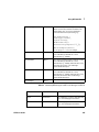
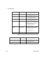
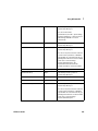
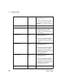
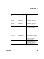
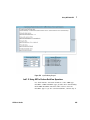
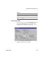
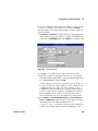
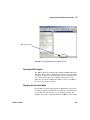
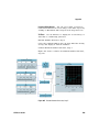
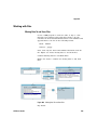
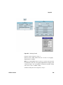
Conventions Used in This Manual
This manual uses the following typographical conventions:
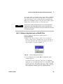
Table 1
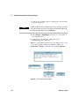
4
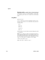
Getting Started
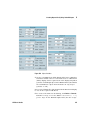
Italicized text is used for emphasis.
File
Computer font represents text that you will see on the
screen in Figures, including menu names, features, and
buttons.
dir filename
In this context, the text in computer font represents an
argument that you type exactly as shown, and the
italicized text represents an argument that you must
replace with an actual value.
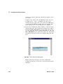
File ⇒ Open
The “⇒” is used in a shorthand notation to show the
location of Agilent VEE features in the menu. For
example, “File ⇒ Open” means to select the File
menu and then select Open.
Sml | Med |
Lrg
Choices in computer font, separated with bars (|),
indicate that you should choose one of the options.
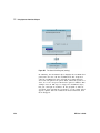
Press Enter
In this context, bold represents a key to press on the
keyboard.
Press Ctrl + O
Represents a combination of keys on the keyboard that
you should press at the same time.
VEE User’s Guide
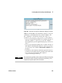
Table of Contents
VEE Pro User’s Guide
Conventions Used in This Manual
. . . . . . . . . . . . . . . . . . . . . . . . . . . . . . . . . . . . . . . . . . . . . . . . . . . . . . . iv
Introduction
Introduction
.......................................................................... 2
Overview of Agilent VEE
...............................................................
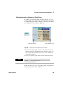
Advantages of Using Agilent VEE for Test Development
.................................
Creating Operator Interfaces in Agilent VEE . . . . . . . . . . . . . . . . . . . . . . . . . . . . . . . . . . . . . . . . . . . .
Leveraging Existing Test Programs with Agilent VEE
....................................
Controlling Instruments with Agilent VEE . . . . . . . . . . . . . . . . . . . . . . . . . . . . . . . . . . . . . . . . . . . . . .
Improving Test Capabilities with Agilent VEE . . . . . . . . . . . . . . . . . . . . . . . . . . . . . . . . . . . . . . . . . . .
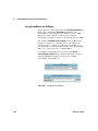
Installing and Learning About Agilent VEE . . . . . . . . . . . . . . . . . . . . . . . . . . . . . . . . . . . . . . . . . . . . . . .
Installing Agilent VEE and I/O Libraries . . . . . . . . . . . . . . . . . . . . . . . . . . . . . . . . . . . . . . . . . . . . . . .
Learning about Agilent VEE . . . . . . . . . . . . . . . . . . . . . . . . . . . . . . . . . . . . . . . . . . . . . . . . . . . . . . . . .
Ordering Free Evaluation Software . . . . . . . . . . . . . . . . . . . . . . . . . . . . . . . . . . . . . . . . . . . . . . . . . . .
3
3
7
9
9
9
11
11
12
13
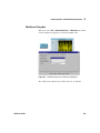
MATLAB Script Overview . . . . . . . . . . . . . . . . . . . . . . . . . . . . . . . . . . . . . . . . . . . . . . . . . . . . . . . . . . . . . . 14
Signal Processing Toolbox . . . . . . . . . . . . . . . . . . . . . . . . . . . . . . . . . . . . . . . . . . . . . . . . . . . . . . . . . . 14
About Full-Featured MATLAB . . . . . . . . . . . . . . . . . . . . . . . . . . . . . . . . . . . . . . . . . . . . . . . . . . . . . . . 15
Obtaining Agilent VEE Support . . . . . . . . . . . . . . . . . . . . . . . . . . . . . . . . . . . . . . . . . . . . . . . . . . . . . . . . . 16
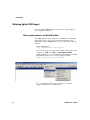
Obtaining Information on the World Wide Web
. . . . . . . . . . . . . . . . . . . . . . . . . . . . . . . . . . . . . . . 16
Sources of Additional Information for MATLAB
1
Using the Agilent VEE Development Environment
Using the Agilent VEE Development Environment
Overview
. . . . . . . . . . . . . . . . . . . . . . . . . . . . . . . . . . . . . . . . . . . 17
. . . . . . . . . . . . . . . . . . . . . . . . . . . . . . . . . . . . . . . . 20
. . . . . . . . . . . . . . . . . . . . . . . . . . . . . . . . . . . . . . . . . . . . . . . . . . . . . . . . . . . . . . . . . . . . . . . . . . . . 21
Interacting with Agilent VEE . . . . . . . . . . . . . . . . . . . . . . . . . . . . . . . . . . . . . . . . . . . . . . . . . . . . . . . . . . . 22
Supported Systems . . . . . . . . . . . . . . . . . . . . . . . . . . . . . . . . . . . . . . . . . . . . . . . . . . . . . . . . . . . . . . . . 22
VEE User’s Guide
1
The Mouse and the Menus
.........................................................
Starting Agilent VEE
...............................................................
The Agilent VEE Window . . . . . . . . . . . . . . . . . . . . . . . . . . . . . . . . . . . . . . . . . . . . . . . . . . . . . . . . . . .
Getting Help . . . . . . . . . . . . . . . . . . . . . . . . . . . . . . . . . . . . . . . . . . . . . . . . . . . . . . . . . . . . . . . . . . . . . .
22
23
23
25
Working with Objects . . . . . . . . . . . . . . . . . . . . . . . . . . . . . . . . . . . . . . . . . . . . . . . . . . . . . . . . . . . . . . . . .
Adding Objects to the Work Area
...................................................
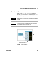
Changing Object Views
............................................................
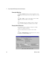
Selecting an Object Menu
..........................................................
Moving an Object
.................................................................
Duplicating (or Cloning) an Object
...................................................
Copying an Object . . . . . . . . . . . . . . . . . . . . . . . . . . . . . . . . . . . . . . . . . . . . . . . . . . . . . . . . . . . . . . . . .
Deleting an Object . . . . . . . . . . . . . . . . . . . . . . . . . . . . . . . . . . . . . . . . . . . . . . . . . . . . . . . . . . . . . . . . .
Pasting an Object
.................................................................
Changing the Size of an Object . . . . . . . . . . . . . . . . . . . . . . . . . . . . . . . . . . . . . . . . . . . . . . . . . . . . . .
Changing the Name (Title) of an Object
..............................................
Selecting or Deselecting Objects
....................................................
Selecting Several Objects
..........................................................
Selecting/Deselecting All Objects . . . . . . . . . . . . . . . . . . . . . . . . . . . . . . . . . . . . . . . . . . . . . . . . . . .
Copying Multiple Objects . . . . . . . . . . . . . . . . . . . . . . . . . . . . . . . . . . . . . . . . . . . . . . . . . . . . . . . . . . .
Editing Objects . . . . . . . . . . . . . . . . . . . . . . . . . . . . . . . . . . . . . . . . . . . . . . . . . . . . . . . . . . . . . . . . . . . .
Creating Data Lines Between Objects . . . . . . . . . . . . . . . . . . . . . . . . . . . . . . . . . . . . . . . . . . . . . . . .
Deleting Data Lines Between Objects . . . . . . . . . . . . . . . . . . . . . . . . . . . . . . . . . . . . . . . . . . . . . . . .
Moving the Entire Work Area . . . . . . . . . . . . . . . . . . . . . . . . . . . . . . . . . . . . . . . . . . . . . . . . . . . . . . . .
Clearing the Work Area
............................................................
Changing Default Preferences
......................................................
29
29
31
33
34
35
36
36
36
37
38
39
39
40
40
41
41
42
43
44
44
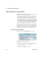
Understanding Pins and Terminals . . . . . . . . . . . . . . . . . . . . . . . . . . . . . . . . . . . . . . . . . . . . . . . . . . . . . .
Adding a Terminal
.................................................................
Editing Terminal Information . . . . . . . . . . . . . . . . . . . . . . . . . . . . . . . . . . . . . . . . . . . . . . . . . . . . . . . .
Deleting a Terminal . . . . . . . . . . . . . . . . . . . . . . . . . . . . . . . . . . . . . . . . . . . . . . . . . . . . . . . . . . . . . . . .
46
48
49
51
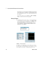
Connecting Objects to Make a Program
. . . . . . . . . . . . . . . . . . . . . . . . . . . . . . . . . . . . . . . . . . . . . . . . . 52
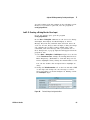
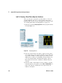
Lab 1-1 Display Waveform Program . . . . . . . . . . . . . . . . . . . . . . . . . . . . . . . . . . . . . . . . . . . . . . . . . . 52
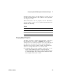
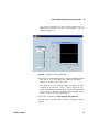
Running a Program
. . . . . . . . . . . . . . . . . . . . . . . . . . . . . . . . . . . . . . . . . . . . . . . . . . . . . . . . . . . . . . . . 54
2
VEE User’s Guide
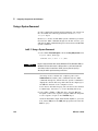
Changing Object Properties . . . . . . . . . . . . . . . . . . . . . . . . . . . . . . . . . . . . . . . . . . . . . . . . . . . . . . . . .
Printing the Screen . . . . . . . . . . . . . . . . . . . . . . . . . . . . . . . . . . . . . . . . . . . . . . . . . . . . . . . . . . . . . . . .
Saving a Program
.................................................................
Exiting (Quitting) Agilent VEE
.......................................................
Re-Starting Agilent VEE and Running a Program . . . . . . . . . . . . . . . . . . . . . . . . . . . . . . . . . . . . . . .
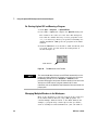
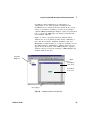
Managing Multiple Windows in the Workspace . . . . . . . . . . . . . . . . . . . . . . . . . . . . . . . . . . . . . . . .
55
58
59
61
62
62
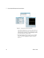
How Agilent VEE Programs Work . . . . . . . . . . . . . . . . . . . . . . . . . . . . . . . . . . . . . . . . . . . . . . . . . . . . . . .
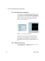
Lab 1-2: Viewing Data Flow and Propagation . . . . . . . . . . . . . . . . . . . . . . . . . . . . . . . . . . . . . . . . . .
Lab 1-3: Adding a Noise Generator . . . . . . . . . . . . . . . . . . . . . . . . . . . . . . . . . . . . . . . . . . . . . . . . . . .
Lab 1-4: Adding an Amplitude Input and Real64 Slider . . . . . . . . . . . . . . . . . . . . . . . . . . . . . . . . . .
65
66
66
69
Chapter Checklist
2
. . . . . . . . . . . . . . . . . . . . . . . . . . . . . . . . . . . . . . . . . . . . . . . . . . . . . . . . . . . . . . . . . . . . 72
Agilent VEE Programming Techniques
Agilent VEE Programming Techniques
Overview
. . . . . . . . . . . . . . . . . . . . . . . . . . . . . . . . . . . . . . . . . . . . . . . . . . 74
. . . . . . . . . . . . . . . . . . . . . . . . . . . . . . . . . . . . . . . . . . . . . . . . . . . . . . . . . . . . . . . . . . . . . . . . . . . . 75
General Techniques
..................................................................
Lab 2-1: Creating a UserObject
......................................................
Lab 2-2: Creating a Dialog Box for User Input
.........................................
Lab 2-3: Using Data Files
...........................................................
Lab 2-4: Creating a Panel View (Operator Interface) . . . . . . . . . . . . . . . . . . . . . . . . . . . . . . . . . . . .
Lab 2-5: Mathematically Processing Data . . . . . . . . . . . . . . . . . . . . . . . . . . . . . . . . . . . . . . . . . . . . .
76
76
83
85
90
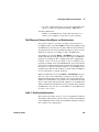
92
Using Online Help
....................................................................
Using the Help Facility
.............................................................
Displaying Help about an Object . . . . . . . . . . . . . . . . . . . . . . . . . . . . . . . . . . . . . . . . . . . . . . . . . . . . .
Finding the Menu Location for an Object . . . . . . . . . . . . . . . . . . . . . . . . . . . . . . . . . . . . . . . . . . . . . .
Other Practice Exercises Using the Help Facility . . . . . . . . . . . . . . . . . . . . . . . . . . . . . . . . . . . . . . .
97
97
98
98
98
Debugging Programs in Agilent VEE
...................................................
Showing Data Flow . . . . . . . . . . . . . . . . . . . . . . . . . . . . . . . . . . . . . . . . . . . . . . . . . . . . . . . . . . . . . . .
Showing Execution Flow
..........................................................
Examining Data on a Line . . . . . . . . . . . . . . . . . . . . . . . . . . . . . . . . . . . . . . . . . . . . . . . . . . . . . . . . . .
Examining Terminals . . . . . . . . . . . . . . . . . . . . . . . . . . . . . . . . . . . . . . . . . . . . . . . . . . . . . . . . . . . . . .
VEE User’s Guide
100
100
102
102
104
3
Using the Alphanumeric Displays for Debugging . . . . . . . . . . . . . . . . . . . . . . . . . . . . . . . . . . . . . .
Using Breakpoints . . . . . . . . . . . . . . . . . . . . . . . . . . . . . . . . . . . . . . . . . . . . . . . . . . . . . . . . . . . . . . . .
Resolving Errors
.................................................................
Using the Go To Button to Locate an Error
...........................................
Using the Call Stack
..............................................................
Following the Order of Events Inside an Object . . . . . . . . . . . . . . . . . . . . . . . . . . . . . . . . . . . . . . .
Following the Execution Order of Objects in a Program
................................
Stepping Through a Program . . . . . . . . . . . . . . . . . . . . . . . . . . . . . . . . . . . . . . . . . . . . . . . . . . . . . . .
Finding an Object in a Complex Program . . . . . . . . . . . . . . . . . . . . . . . . . . . . . . . . . . . . . . . . . . . . .
104
105
107
107
108
109
112
113
114
Practice Programs . . . . . . . . . . . . . . . . . . . . . . . . . . . . . . . . . . . . . . . . . . . . . . . . . . . . . . . . . . . . . . . . . . . 115
2-6: Generate a Random Number . . . . . . . . . . . . . . . . . . . . . . . . . . . . . . . . . . . . . . . . . . . . . . . . . . . 115
2-7: Setting and Getting a Global Variable . . . . . . . . . . . . . . . . . . . . . . . . . . . . . . . . . . . . . . . . . . . . 116
Documenting Agilent VEE Programs
. . . . . . . . . . . . . . . . . . . . . . . . . . . . . . . . . . . . . . . . . . . . . . . . . . . 119
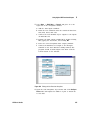
Documenting Objects with Description Dialog Boxes . . . . . . . . . . . . . . . . . . . . . . . . . . . . . . . . . . 119
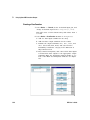
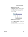
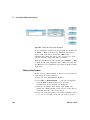
Generating Documentation Automatically
. . . . . . . . . . . . . . . . . . . . . . . . . . . . . . . . . . . . . . . . . . . 120
Chapter Checklist
3
. . . . . . . . . . . . . . . . . . . . . . . . . . . . . . . . . . . . . . . . . . . . . . . . . . . . . . . . . . . . . . . . . . . 125
Easy Ways to Control Instruments
Easy Ways To Control Instruments
. . . . . . . . . . . . . . . . . . . . . . . . . . . . . . . . . . . . . . . . . . . . . . . . . . . . . 128
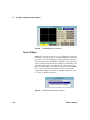
Overview . . . . . . . . . . . . . . . . . . . . . . . . . . . . . . . . . . . . . . . . . . . . . . . . . . . . . . . . . . . . . . . . . . . . . . . . . . .
Panel Drivers
....................................................................
Direct I/O Object . . . . . . . . . . . . . . . . . . . . . . . . . . . . . . . . . . . . . . . . . . . . . . . . . . . . . . . . . . . . . . . . .
PC Plug-in Boards with I/O Library
.................................................
VXIplug&play Drivers
.............................................................
129
129
130
131
131
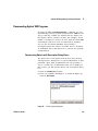
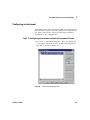
Configuring an Instrument . . . . . . . . . . . . . . . . . . . . . . . . . . . . . . . . . . . . . . . . . . . . . . . . . . . . . . . . . . . .
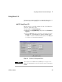
Lab 3-1: Configuring an Instrument without the Instrument Present . . . . . . . . . . . . . . . . . . . . .
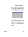
Selecting an Instrument to Use in a Program . . . . . . . . . . . . . . . . . . . . . . . . . . . . . . . . . . . . . . . . .
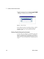
Adding the Physical Instrument to the Configuration . . . . . . . . . . . . . . . . . . . . . . . . . . . . . . . . . .
133
133
139
140
Using a Panel Driver
. . . . . . . . . . . . . . . . . . . . . . . . . . . . . . . . . . . . . . . . . . . . . . . . . . . . . . . . . . . . . . . . . 142
Lab 3-2: Changing Settings on a Panel Driver . . . . . . . . . . . . . . . . . . . . . . . . . . . . . . . . . . . . . . . . . 142
4
VEE User’s Guide
Moving to Other Panels on the Same Driver . . . . . . . . . . . . . . . . . . . . . . . . . . . . . . . . . . . . . . . . . . 144
Deleting Data Input or Output Terminals . . . . . . . . . . . . . . . . . . . . . . . . . . . . . . . . . . . . . . . . . . . . . 146
On Your Own
. . . . . . . . . . . . . . . . . . . . . . . . . . . . . . . . . . . . . . . . . . . . . . . . . . . . . . . . . . . . . . . . . . . . 146
Using Direct I/O
....................................................................
Lab 3-3: Using Direct I/O
..........................................................
Sending a Single Text Command to an Instrument
....................................
Sending an Expression List to an Instrument . . . . . . . . . . . . . . . . . . . . . . . . . . . . . . . . . . . . . . . . .
Reading Data From an Instrument
..................................................
Uploading and Downloading Instrument States
......................................
147
147
148
150
151
155
Using PC Plug-in Boards
.............................................................
Data Translation's Visual Programming Interface (VPI)
................................
Amplicon . . . . . . . . . . . . . . . . . . . . . . . . . . . . . . . . . . . . . . . . . . . . . . . . . . . . . . . . . . . . . . . . . . . . . . . .
ComputerBoards PC Plug-ins
......................................................
Meilhaus Electronic ME-DriverSystem . . . . . . . . . . . . . . . . . . . . . . . . . . . . . . . . . . . . . . . . . . . . . . .
157
157
157
158
160
Using a VXIplug&play Driver
. . . . . . . . . . . . . . . . . . . . . . . . . . . . . . . . . . . . . . . . . . . . . . . . . . . . . . . . . . 163
Lab 3-4: Configuring a VXIplug&play Driver
. . . . . . . . . . . . . . . . . . . . . . . . . . . . . . . . . . . . . . . . . . 163
Other I/O Features
. . . . . . . . . . . . . . . . . . . . . . . . . . . . . . . . . . . . . . . . . . . . . . . . . . . . . . . . . . . . . . . . . . 168
Chapter Checklist
. . . . . . . . . . . . . . . . . . . . . . . . . . . . . . . . . . . . . . . . . . . . . . . . . . . . . . . . . . . . . . . . . . . 169
4
Analyzing and Displaying Test Data
Analyzing and Displaying Test Data
Overview
. . . . . . . . . . . . . . . . . . . . . . . . . . . . . . . . . . . . . . . . . . . . . . . . . . . . 172
. . . . . . . . . . . . . . . . . . . . . . . . . . . . . . . . . . . . . . . . . . . . . . . . . . . . . . . . . . . . . . . . . . . . . . . . . . . 173
Agilent VEE Data Shapes and Data Types
Agilent VEE Analysis Capabilities
. . . . . . . . . . . . . . . . . . . . . . . . . . . . . . . . . . . . . . . . . . . . . . . 174
. . . . . . . . . . . . . . . . . . . . . . . . . . . . . . . . . . . . . . . . . . . . . . . . . . . . . . 177
Using Built-In Math Objects . . . . . . . . . . . . . . . . . . . . . . . . . . . . . . . . . . . . . . . . . . . . . . . . . . . . . . . . . . . 178
Accessing a Built-in Operator or Function
. . . . . . . . . . . . . . . . . . . . . . . . . . . . . . . . . . . . . . . . . . . 178
Lab 4-1: Calculating Standard Deviation
. . . . . . . . . . . . . . . . . . . . . . . . . . . . . . . . . . . . . . . . . . . . . 180
Creating Expressions with the Formula Object . . . . . . . . . . . . . . . . . . . . . . . . . . . . . . . . . . . . . . . . . . . 182
Evaluating an Expression with the Formula Object . . . . . . . . . . . . . . . . . . . . . . . . . . . . . . . . . . . . 183
VEE User’s Guide
5
Using an Agilent VEE Function in the Formula Object
. . . . . . . . . . . . . . . . . . . . . . . . . . . . . . . . . 184
On Your Own
. . . . . . . . . . . . . . . . . . . . . . . . . . . . . . . . . . . . . . . . . . . . . . . . . . . . . . . . . . . . . . . . . . . . 186
Using MATLAB Script in Agilent VEE
. . . . . . . . . . . . . . . . . . . . . . . . . . . . . . . . . . . . . . . . . . . . . . . . . . 188
Including a MATLAB Script Object in Agilent VEE
. . . . . . . . . . . . . . . . . . . . . . . . . . . . . . . . . . . . 191
Working with Data Types . . . . . . . . . . . . . . . . . . . . . . . . . . . . . . . . . . . . . . . . . . . . . . . . . . . . . . . . . . 192
Displaying Test Data
. . . . . . . . . . . . . . . . . . . . . . . . . . . . . . . . . . . . . . . . . . . . . . . . . . . . . . . . . . . . . . . . . 195
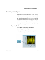
Customizing Test Data Displays
.......................................................
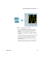
Displaying a Waveform
...........................................................
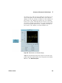
Changing the X and Y Scales . . . . . . . . . . . . . . . . . . . . . . . . . . . . . . . . . . . . . . . . . . . . . . . . . . . . . . .
Zooming in on Part of the Waveform . . . . . . . . . . . . . . . . . . . . . . . . . . . . . . . . . . . . . . . . . . . . . . . .
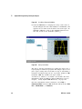
Adding Delta Markers to the Display . . . . . . . . . . . . . . . . . . . . . . . . . . . . . . . . . . . . . . . . . . . . . . . .
Changing the Color of the Trace . . . . . . . . . . . . . . . . . . . . . . . . . . . . . . . . . . . . . . . . . . . . . . . . . . . . .
For Additional Practice . . . . . . . . . . . . . . . . . . . . . . . . . . . . . . . . . . . . . . . . . . . . . . . . . . . . . . . . . . . .
Chapter Checklist
5
. . . . . . . . . . . . . . . . . . . . . . . . . . . . . . . . . . . . . . . . . . . . . . . . . . . . . . . . . . . . . . . . . . . 201
Storing and Retrieving Test Results
Storing and Retrieving Test Results
Overview
197
197
198
198
198
200
200
. . . . . . . . . . . . . . . . . . . . . . . . . . . . . . . . . . . . . . . . . . . . . . . . . . . . 204
. . . . . . . . . . . . . . . . . . . . . . . . . . . . . . . . . . . . . . . . . . . . . . . . . . . . . . . . . . . . . . . . . . . . . . . . . . . 205
Using Arrays to Store Test Results . . . . . . . . . . . . . . . . . . . . . . . . . . . . . . . . . . . . . . . . . . . . . . . . . . . . . 206
Lab 5-1: Creating an Array for Test Results
. . . . . . . . . . . . . . . . . . . . . . . . . . . . . . . . . . . . . . . . . . 207
Lab 5-2: Extracting Values from an Array
. . . . . . . . . . . . . . . . . . . . . . . . . . . . . . . . . . . . . . . . . . . . 208
Using the To/From File Objects
.......................................................
Understanding I/O Transactions
...................................................
I/O Transaction Format
...........................................................
Lab 5-3: Using the To/From File Objects
.............................................
Sending a Text String to a File
.....................................................
Sending a Time Stamp to a File . . . . . . . . . . . . . . . . . . . . . . . . . . . . . . . . . . . . . . . . . . . . . . . . . . . . .
Sending a Real Array to a File
......................................................
Retrieving Data with the From File Object . . . . . . . . . . . . . . . . . . . . . . . . . . . . . . . . . . . . . . . . . . . .
Using Records to Store Mixed Data Types
6
210
210
212
214
214
215
217
218
. . . . . . . . . . . . . . . . . . . . . . . . . . . . . . . . . . . . . . . . . . . . . . 222
VEE User’s Guide
Building a Record
................................................................
Getting a Field From a Record . . . . . . . . . . . . . . . . . . . . . . . . . . . . . . . . . . . . . . . . . . . . . . . . . . . . . .
Setting a Field in a Record . . . . . . . . . . . . . . . . . . . . . . . . . . . . . . . . . . . . . . . . . . . . . . . . . . . . . . . . .
Unbuilding a Record in a Single Step . . . . . . . . . . . . . . . . . . . . . . . . . . . . . . . . . . . . . . . . . . . . . . . .
223
225
227
230
Using DataSets to Store and Retrieve Records
. . . . . . . . . . . . . . . . . . . . . . . . . . . . . . . . . . . . . . . . . . 232
Lab 5-5: Using DataSets . . . . . . . . . . . . . . . . . . . . . . . . . . . . . . . . . . . . . . . . . . . . . . . . . . . . . . . . . . . 232
Storing and Retrieving a Record from a DataSet . . . . . . . . . . . . . . . . . . . . . . . . . . . . . . . . . . . . . . . 232
Customizing a Simple Test Database . . . . . . . . . . . . . . . . . . . . . . . . . . . . . . . . . . . . . . . . . . . . . . . . . . .
Lab 5-6: Using Search and Sort Operations with DataSets . . . . . . . . . . . . . . . . . . . . . . . . . . . . . .
Performing a Search Operation With DataSets
.......................................
Creating an Operator Interface for a Search Operation . . . . . . . . . . . . . . . . . . . . . . . . . . . . . . . . .
Performing a Sort Operation on a Record Field
.......................................
Chapter Checklist
6
. . . . . . . . . . . . . . . . . . . . . . . . . . . . . . . . . . . . . . . . . . . . . . . . . . . . . . . . . . . . . . . . . . . 246
Creating Reports Easily Using ActiveX
Creating Reports Easily Using ActiveX
Overview
237
237
237
238
244
. . . . . . . . . . . . . . . . . . . . . . . . . . . . . . . . . . . . . . . . . . . . . . . . . 248
. . . . . . . . . . . . . . . . . . . . . . . . . . . . . . . . . . . . . . . . . . . . . . . . . . . . . . . . . . . . . . . . . . . . . . . . . . . 249
ActiveX Automation in Agilent VEE
....................................................
Listing ActiveX Automation Type Libraries . . . . . . . . . . . . . . . . . . . . . . . . . . . . . . . . . . . . . . . . . . .
Creating and Using ActiveX Programs with Agilent VEE
...............................
Performing Operations Using ActiveX Statements . . . . . . . . . . . . . . . . . . . . . . . . . . . . . . . . . . . . .
Using CreateObject and GetObject . . . . . . . . . . . . . . . . . . . . . . . . . . . . . . . . . . . . . . . . . . . . . . . . . .
250
250
251
252
254
Sending Agilent VEE Data to MS Excel
. . . . . . . . . . . . . . . . . . . . . . . . . . . . . . . . . . . . . . . . . . . . . . . . . 255
Lab 6-1: Sending Agilent VEE Data to MS Excel
. . . . . . . . . . . . . . . . . . . . . . . . . . . . . . . . . . . . . . 255
Creating an Agilent VEE to MS Excel Template . . . . . . . . . . . . . . . . . . . . . . . . . . . . . . . . . . . . . . . . . . .
Lab 6-2: Creating an Agilent VEE to MS Excel Template . . . . . . . . . . . . . . . . . . . . . . . . . . . . . . . .
On Your Own . . . . . . . . . . . . . . . . . . . . . . . . . . . . . . . . . . . . . . . . . . . . . . . . . . . . . . . . . . . . . . . . . . . . .
Extending Capabilities With MS Excel . . . . . . . . . . . . . . . . . . . . . . . . . . . . . . . . . . . . . . . . . . . . . . .
264
264
267
267
Using MS Word for Agilent VEE Reports . . . . . . . . . . . . . . . . . . . . . . . . . . . . . . . . . . . . . . . . . . . . . . . . 270
Lab 6-3: Using MS Word for Agilent VEE Reports
. . . . . . . . . . . . . . . . . . . . . . . . . . . . . . . . . . . . . 270
VEE User’s Guide
7
Chapter Checklist
. . . . . . . . . . . . . . . . . . . . . . . . . . . . . . . . . . . . . . . . . . . . . . . . . . . . . . . . . . . . . . . . . . . 277
7
Using .NET with VEE
Using .NET with VEE
What is .NET?
. . . . . . . . . . . . . . . . . . . . . . . . . . . . . . . . . . . . . . . . . . . . . . . . . . . . . . . . . . . . . . . . . 280
. . . . . . . . . . . . . . . . . . . . . . . . . . . . . . . . . . . . . . . . . . . . . . . . . . . . . . . . . . . . . . . . . . . . . . 281
VEE and the .NET Framework
.NET Assembly References
. . . . . . . . . . . . . . . . . . . . . . . . . . . . . . . . . . . . . . . . . . . . . . . . . . . . . . . . . 282
. . . . . . . . . . . . . . . . . . . . . . . . . . . . . . . . . . . . . . . . . . . . . . . . . . . . . . . . 283
Importing a Namespace into VEE
. . . . . . . . . . . . . . . . . . . . . . . . . . . . . . . . . . . . . . . . . . . . . . . . . . . . . . 288
VEE and Primary Interop Assemblies
. . . . . . . . . . . . . . . . . . . . . . . . . . . . . . . . . . . . . . . . . . . . . . . . . . . 292
Programming Practices . . . . . . . . . . . . . . . . . . . . . . . . . . . . . . . . . . . . . . . . . . . . . . . . . . . . . . . . . . . . . . .
Converting Data Types Between .NET and VEE . . . . . . . . . . . . . . . . . . . . . . . . . . . . . . . . . . . . . . .
Calling an Instance Method . . . . . . . . . . . . . . . . . . . . . . . . . . . . . . . . . . . . . . . . . . . . . . . . . . . . . . . .
Calling a Shared/Static Method . . . . . . . . . . . . . . . . . . . . . . . . . . . . . . . . . . . . . . . . . . . . . . . . . . . .
.NET Programming Tips
...........................................................
Lab 5-1: Using .NET to Select Files . . . . . . . . . . . . . . . . . . . . . . . . . . . . . . . . . . . . . . . . . . . . . . . . . .
Lab 5-2: Using .NET to Perform DateTime Operations . . . . . . . . . . . . . . . . . . . . . . . . . . . . . . . . . .
Lab 5-3: Using .NET to Get File Information
..........................................
.NET and IVI Drivers
293
293
300
301
301
302
305
309
. . . . . . . . . . . . . . . . . . . . . . . . . . . . . . . . . . . . . . . . . . . . . . . . . . . . . . . . . . . . . . . . . 311
Assemblies . . . . . . . . . . . . . . . . . . . . . . . . . . . . . . . . . . . . . . . . . . . . . . . . . . . . . . . . . . . . . . . . . . . . . . . . . 313
Installing a New Assembly
. . . . . . . . . . . . . . . . . . . . . . . . . . . . . . . . . . . . . . . . . . . . . . . . . . . . . . . . 313
Updating an Assembly
. . . . . . . . . . . . . . . . . . . . . . . . . . . . . . . . . . . . . . . . . . . . . . . . . . . . . . . . . . . . 313
Distributing the VEE Runtime
VEE and .NET Security
. . . . . . . . . . . . . . . . . . . . . . . . . . . . . . . . . . . . . . . . . . . . . . . . . . . . . . . . . 314
. . . . . . . . . . . . . . . . . . . . . . . . . . . . . . . . . . . . . . . . . . . . . . . . . . . . . . . . . . . . . . . 315
.NET Terminology
...................................................................
Assembly
.......................................................................
Primary Interop Assembly (PIA)
....................................................
Namespace
.....................................................................
Reference
.......................................................................
Class
...........................................................................
8
316
316
316
316
317
317
VEE User’s Guide
Shared or Static Members . . . . . . . . . . . . . . . . . . . . . . . . . . . . . . . . . . . . . . . . . . . . . . . . . . . . . . . . . 317
Instance Member
. . . . . . . . . . . . . . . . . . . . . . . . . . . . . . . . . . . . . . . . . . . . . . . . . . . . . . . . . . . . . . . . 317
Chapter Checklist
8
. . . . . . . . . . . . . . . . . . . . . . . . . . . . . . . . . . . . . . . . . . . . . . . . . . . . . . . . . . . . . . . . . . . 318
Integrating Programs for the PC
Integrating Programs In Other Languages
Overview
. . . . . . . . . . . . . . . . . . . . . . . . . . . . . . . . . . . . . . . . . . . . . . 320
. . . . . . . . . . . . . . . . . . . . . . . . . . . . . . . . . . . . . . . . . . . . . . . . . . . . . . . . . . . . . . . . . . . . . . . . . . . 321
Understanding the Execute Program Object . . . . . . . . . . . . . . . . . . . . . . . . . . . . . . . . . . . . . . . . . . . . . 322
Using the Execute Program Object . . . . . . . . . . . . . . . . . . . . . . . . . . . . . . . . . . . . . . . . . . . . . . . . . . 322
Using a System Command . . . . . . . . . . . . . . . . . . . . . . . . . . . . . . . . . . . . . . . . . . . . . . . . . . . . . . . . . . . . 324
Lab 8-1: Using a System Command
. . . . . . . . . . . . . . . . . . . . . . . . . . . . . . . . . . . . . . . . . . . . . . . . . 324
Writing Programs That Port Easily . . . . . . . . . . . . . . . . . . . . . . . . . . . . . . . . . . . . . . . . . . . . . . . . . . 326
Chapter Checklist
9
. . . . . . . . . . . . . . . . . . . . . . . . . . . . . . . . . . . . . . . . . . . . . . . . . . . . . . . . . . . . . . . . . . . 328
Using Agilent VEE Functions
Using Agilent VEE Functions
Overview
. . . . . . . . . . . . . . . . . . . . . . . . . . . . . . . . . . . . . . . . . . . . . . . . . . . . . . . . . . 330
. . . . . . . . . . . . . . . . . . . . . . . . . . . . . . . . . . . . . . . . . . . . . . . . . . . . . . . . . . . . . . . . . . . . . . . . . . . 331
Using Functions . . . . . . . . . . . . . . . . . . . . . . . . . . . . . . . . . . . . . . . . . . . . . . . . . . . . . . . . . . . . . . . . . . . . .
Defining an Agilent VEE Function . . . . . . . . . . . . . . . . . . . . . . . . . . . . . . . . . . . . . . . . . . . . . . . . . . .
The Differences Between UserObjects and UserFunctions
............................
Lab 9-1: UserFunction Operations
..................................................
Creating a UserFunction . . . . . . . . . . . . . . . . . . . . . . . . . . . . . . . . . . . . . . . . . . . . . . . . . . . . . . . . . . .
Editing a UserFunction . . . . . . . . . . . . . . . . . . . . . . . . . . . . . . . . . . . . . . . . . . . . . . . . . . . . . . . . . . . .
Calling a UserFunction from an Expression
..........................................
Generating a Call to a UserFunction
................................................
UserFunctions and the Program Explorer
............................................
332
332
333
333
334
336
339
340
342
Using Libraries With Agilent VEE UserFunctions . . . . . . . . . . . . . . . . . . . . . . . . . . . . . . . . . . . . . . . . .
Lab 9-2: Creating and Merging a Library of UserFunctions
.............................
Creating a Library of UserFunctions . . . . . . . . . . . . . . . . . . . . . . . . . . . . . . . . . . . . . . . . . . . . . . . . .
Creating Another Program and Merging in the Library . . . . . . . . . . . . . . . . . . . . . . . . . . . . . . . . .
344
344
345
350
VEE User’s Guide
9
Lab 9-3: Importing and Deleting Libraries
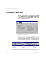
Finding Functions in Large Programs
. . . . . . . . . . . . . . . . . . . . . . . . . . . . . . . . . . . . . . . . . . . . 351
. . . . . . . . . . . . . . . . . . . . . . . . . . . . . . . . . . . . . . . . . . . . . . . . . . . 356
Merging Agilent VEE Programs
. . . . . . . . . . . . . . . . . . . . . . . . . . . . . . . . . . . . . . . . . . . . . . . . . . . . . . . 358
Lab 9-4: Merging a Bar Chart Display Program . . . . . . . . . . . . . . . . . . . . . . . . . . . . . . . . . . . . . . . . 358
Chapter Checklist
10
Test Sequencing
Overview
. . . . . . . . . . . . . . . . . . . . . . . . . . . . . . . . . . . . . . . . . . . . . . . . . . . . . . . . . . . . . . . . . . . 360
Test Sequencing
. . . . . . . . . . . . . . . . . . . . . . . . . . . . . . . . . . . . . . . . . . . . . . . . . . . . . . . . . . . . . . . . . . . . 362
. . . . . . . . . . . . . . . . . . . . . . . . . . . . . . . . . . . . . . . . . . . . . . . . . . . . . . . . . . . . . . . . . . . . . . . . . . . 363
Using the Sequencer Object
. . . . . . . . . . . . . . . . . . . . . . . . . . . . . . . . . . . . . . . . . . . . . . . . . . . . . . . . . . 365
Creating a Test Execution Order
.......................................................
Lab 10-1: Configuring a Test
.......................................................
Adding or Inserting or Deleting a Test
...............................................
Accessing Logged Test Data . . . . . . . . . . . . . . . . . . . . . . . . . . . . . . . . . . . . . . . . . . . . . . . . . . . . . . .
366
366
372
374
Passing Data in the Sequencer . . . . . . . . . . . . . . . . . . . . . . . . . . . . . . . . . . . . . . . . . . . . . . . . . . . . . . . .
Lab 10-2: Passing Data Using an Input Terminal
......................................
Passing Data Using a Global Variable
...............................................
Comparing a Waveform Output with a Mask
.........................................
377
377
380
384
Analyzing Data from the Sequencer . . . . . . . . . . . . . . . . . . . . . . . . . . . . . . . . . . . . . . . . . . . . . . . . . . . . 389
Lab 10-3: Analyzing Several Runs of Data from the Sequencer . . . . . . . . . . . . . . . . . . . . . . . . . . 390
Storing and Retrieving Logged Data . . . . . . . . . . . . . . . . . . . . . . . . . . . . . . . . . . . . . . . . . . . . . . . . . . . . 393
Lab 10-4: Using the To/From File Objects with Logged Data . . . . . . . . . . . . . . . . . . . . . . . . . . . . 393
Using the To/From DataSet Objects with Logged Data
. . . . . . . . . . . . . . . . . . . . . . . . . . . . . . . . 394
Chapter Checklist
11
. . . . . . . . . . . . . . . . . . . . . . . . . . . . . . . . . . . . . . . . . . . . . . . . . . . . . . . . . . . . . . . . . . . 396
Using Operator Interfaces
Using Operator Interfaces
Overview
10
. . . . . . . . . . . . . . . . . . . . . . . . . . . . . . . . . . . . . . . . . . . . . . . . . . . . . . . . . . . . 398
. . . . . . . . . . . . . . . . . . . . . . . . . . . . . . . . . . . . . . . . . . . . . . . . . . . . . . . . . . . . . . . . . . . . . . . . . . . 399
VEE User’s Guide
Key Points Concerning Operator Interfaces
.............................................
Creating an Operator Interface
.....................................................
Moving Between Panel View and Detail View . . . . . . . . . . . . . . . . . . . . . . . . . . . . . . . . . . . . . . . .
Customizing an Operator Interface . . . . . . . . . . . . . . . . . . . . . . . . . . . . . . . . . . . . . . . . . . . . . . . . . .
400
400
401
401
Using Operator Interface Objects . . . . . . . . . . . . . . . . . . . . . . . . . . . . . . . . . . . . . . . . . . . . . . . . . . . . . .
Colors, Fonts, and Indicators . . . . . . . . . . . . . . . . . . . . . . . . . . . . . . . . . . . . . . . . . . . . . . . . . . . . . . .
Graphic Images
..................................................................
Displaying a Control for Operator Input . . . . . . . . . . . . . . . . . . . . . . . . . . . . . . . . . . . . . . . . . . . . . .
Displaying a Dialog Box for Operator Input . . . . . . . . . . . . . . . . . . . . . . . . . . . . . . . . . . . . . . . . . . .
Displaying a Toggle Control for the Operator
.........................................
Aligning Objects in the Operator Interface
...........................................
Other Panel Formatting Features
...................................................
Creating an Operator Interface for the Keyboard Only . . . . . . . . . . . . . . . . . . . . . . . . . . . . . . . . . .
Selecting Screen Colors . . . . . . . . . . . . . . . . . . . . . . . . . . . . . . . . . . . . . . . . . . . . . . . . . . . . . . . . . . .
Securing a Program (Creating a RunTime Version)
...................................
Displaying a Pop-Up Panel During Execution
........................................
Creating a Status Panel
...........................................................
403
403
404
405
408
410
411
412
412
415
416
417
417
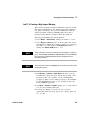
Common Tasks In Creating Operator Interfaces . . . . . . . . . . . . . . . . . . . . . . . . . . . . . . . . . . . . . . . . . .
Lab 11-1: Using Menus . . . . . . . . . . . . . . . . . . . . . . . . . . . . . . . . . . . . . . . . . . . . . . . . . . . . . . . . . . . .
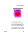
Lab 11-2: Importing Bitmaps for Panel Backgrounds . . . . . . . . . . . . . . . . . . . . . . . . . . . . . . . . . . .
Lab 11-3: Creating a High Impact Warning
...........................................
Lab 11-4: Using an ActiveX Control
.................................................
Lab 11-5: Creating a Status Panel . . . . . . . . . . . . . . . . . . . . . . . . . . . . . . . . . . . . . . . . . . . . . . . . . . .
419
419
425
427
432
434
Chapter Checklist
12
Overview
. . . . . . . . . . . . . . . . . . . . . . . . . . . . . . . . . . . . . . . . . . . . . . . . . . . . . . . . . . . . . . . . . . . 439
Optimizing Agilent VEE Programs
. . . . . . . . . . . . . . . . . . . . . . . . . . . . . . . . . . . . . . . . . . . . . . . . . . . . . . . . . . . . . . . . . . . . . . . . . . . 443
Basic Techniques for Optimizing Programs . . . . . . . . . . . . . . . . . . . . . . . . . . . . . . . . . . . . . . . . . . . . . .
Perform Math on Arrays Whenever Possible . . . . . . . . . . . . . . . . . . . . . . . . . . . . . . . . . . . . . . . . .
Make Objects into Icons Whenever Possible . . . . . . . . . . . . . . . . . . . . . . . . . . . . . . . . . . . . . . . . .
Reduce the Number of Objects in Programs
.........................................
VEE User’s Guide
444
444
445
446
11
Other Ways to Optimize Agilent VEE Programs
. . . . . . . . . . . . . . . . . . . . . . . . . . . . . . . . . . . . . . . 448
Overview of Compiled Functions
......................................................
Benefits of Using Compiled Functions . . . . . . . . . . . . . . . . . . . . . . . . . . . . . . . . . . . . . . . . . . . . . . .
Design Considerations in Using Compiled Functions
..................................
Guidelines in Using Compiled Functions . . . . . . . . . . . . . . . . . . . . . . . . . . . . . . . . . . . . . . . . . . . . .
450
450
450
451
Using Dynamic Link Libraries
.........................................................
Integrating a DLL into an Agilent VEE Program
.......................................
An Example Using a DLL . . . . . . . . . . . . . . . . . . . . . . . . . . . . . . . . . . . . . . . . . . . . . . . . . . . . . . . . . . .
Execute Program Object versus Compiled Functions
..................................
453
453
455
458
Agilent VEE Execution Modes . . . . . . . . . . . . . . . . . . . . . . . . . . . . . . . . . . . . . . . . . . . . . . . . . . . . . . . . .
The Agilent VEE Compiler
.........................................................
Changing the Execution Mode
.....................................................
Default Preferences Button on Toolbar
..............................................
Effect of Changing the Execution Mode
.............................................
460
461
461
462
463
The Agilent VEE Profiler
Chapter Checklist
13
. . . . . . . . . . . . . . . . . . . . . . . . . . . . . . . . . . . . . . . . . . . . . . . . . . . . . . . . . . . . . . 468
. . . . . . . . . . . . . . . . . . . . . . . . . . . . . . . . . . . . . . . . . . . . . . . . . . . . . . . . . . . . . . . . . . . 470
Platform Specifics and Web Monitoring
Platform Specifics and Web Monitoring
Overview
. . . . . . . . . . . . . . . . . . . . . . . . . . . . . . . . . . . . . . . . . . . . . . . . 472
. . . . . . . . . . . . . . . . . . . . . . . . . . . . . . . . . . . . . . . . . . . . . . . . . . . . . . . . . . . . . . . . . . . . . . . . . . . 473
The Callable VEE ActiveX Automation Server
. . . . . . . . . . . . . . . . . . . . . . . . . . . . . . . . . . . . . . . . . . . 474
Web-enablement Technologies
. . . . . . . . . . . . . . . . . . . . . . . . . . . . . . . . . . . . . . . . . . . . . . . . . . . . . . . 475
Overview of Web Technologies . . . . . . . . . . . . . . . . . . . . . . . . . . . . . . . . . . . . . . . . . . . . . . . . . . . . . 475
Web Monitoring with Agilent VEE
.....................................................
General Guidelines and Tips
.......................................................
Providing Agilent VEE Data to a Remote User
........................................
How a Remote User Accesses Agilent VEE on Your System
............................
Displaying the Agilent VEE Web Server Page . . . . . . . . . . . . . . . . . . . . . . . . . . . . . . . . . . . . . . . . .
Lab 13-1: Practice Session with Agilent VEE Web Browser
............................
12
479
479
479
483
486
488
VEE User’s Guide
Restricting Access to Programs Viewed over the Web
Chapter Checklist
. . . . . . . . . . . . . . . . . . . . . . . . . . . . . . . . . 491
. . . . . . . . . . . . . . . . . . . . . . . . . . . . . . . . . . . . . . . . . . . . . . . . . . . . . . . . . . . . . . . . . . . 495
Appendix A: Additional Lab Exercises
Additional Lab Exercises
. . . . . . . . . . . . . . . . . . . . . . . . . . . . . . . . . . . . . . . . . . . . . . . . . . . . . . . . . . . . . 498
General Programming Techniques
.....................................................
Apple Bagger . . . . . . . . . . . . . . . . . . . . . . . . . . . . . . . . . . . . . . . . . . . . . . . . . . . . . . . . . . . . . . . . . . . .
Testing Numbers . . . . . . . . . . . . . . . . . . . . . . . . . . . . . . . . . . . . . . . . . . . . . . . . . . . . . . . . . . . . . . . . .
Collecting Random Numbers . . . . . . . . . . . . . . . . . . . . . . . . . . . . . . . . . . . . . . . . . . . . . . . . . . . . . . .
Random Number Generator . . . . . . . . . . . . . . . . . . . . . . . . . . . . . . . . . . . . . . . . . . . . . . . . . . . . . . . .
Using Masks
....................................................................
499
499
501
505
508
510
Using Strings and Globals
. . . . . . . . . . . . . . . . . . . . . . . . . . . . . . . . . . . . . . . . . . . . . . . . . . . . . . . . . . . . 514
Manipulating Strings and Globals . . . . . . . . . . . . . . . . . . . . . . . . . . . . . . . . . . . . . . . . . . . . . . . . . . . 514
Optimizing Techniques
. . . . . . . . . . . . . . . . . . . . . . . . . . . . . . . . . . . . . . . . . . . . . . . . . . . . . . . . . . . . . . . 516
UserObjects
. . . . . . . . . . . . . . . . . . . . . . . . . . . . . . . . . . . . . . . . . . . . . . . . . . . . . . . . . . . . . . . . . . . . . . . . 518
Random Noise UserObject . . . . . . . . . . . . . . . . . . . . . . . . . . . . . . . . . . . . . . . . . . . . . . . . . . . . . . . . . 518
Agilent VEE UserFunctions
. . . . . . . . . . . . . . . . . . . . . . . . . . . . . . . . . . . . . . . . . . . . . . . . . . . . . . . . . . . 521
Using UserFunctions . . . . . . . . . . . . . . . . . . . . . . . . . . . . . . . . . . . . . . . . . . . . . . . . . . . . . . . . . . . . . . 521
Importing and Deleting Libraries of UserFunctions . . . . . . . . . . . . . . . . . . . . . . . . . . . . . . . . . . . . 526
Creating Operator Panels and Pop-ups
. . . . . . . . . . . . . . . . . . . . . . . . . . . . . . . . . . . . . . . . . . . . . . . . . 528
Working with Files
. . . . . . . . . . . . . . . . . . . . . . . . . . . . . . . . . . . . . . . . . . . . . . . . . . . . . . . . . . . . . . . . . . 533
Moving Data To and From Files . . . . . . . . . . . . . . . . . . . . . . . . . . . . . . . . . . . . . . . . . . . . . . . . . . . . . 533
Records . . . . . . . . . . . . . . . . . . . . . . . . . . . . . . . . . . . . . . . . . . . . . . . . . . . . . . . . . . . . . . . . . . . . . . . . . . . . 535
Manipulating Records
. . . . . . . . . . . . . . . . . . . . . . . . . . . . . . . . . . . . . . . . . . . . . . . . . . . . . . . . . . . . 535
Test Sequencing
. . . . . . . . . . . . . . . . . . . . . . . . . . . . . . . . . . . . . . . . . . . . . . . . . . . . . . . . . . . . . . . . . . . . 541
Glossary
VEE User’s Guide
13
14
VEE User’s Guide
Table of Figures
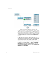
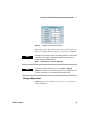
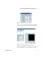
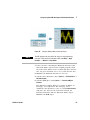
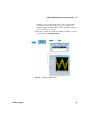
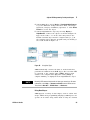
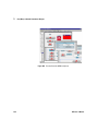
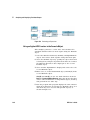
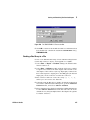
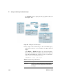
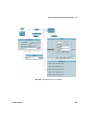
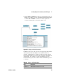
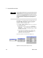
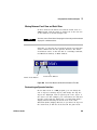
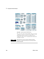
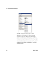
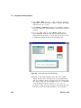
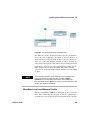
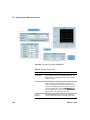
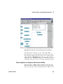
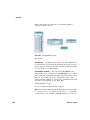
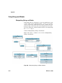
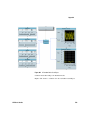
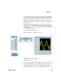
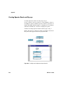
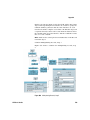
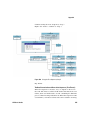
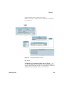
Figure 1. The VEE Development Environment . . . . . . . . . . . . . . . . . . . . . . . . . . . . . . . . . . . . . . . . . .
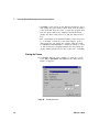
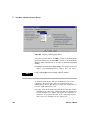
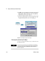
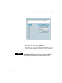
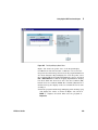
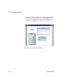
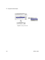
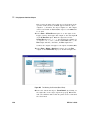
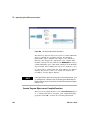
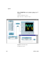
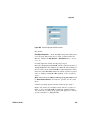
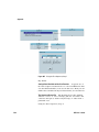
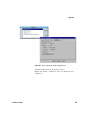
Figure 2. The VEE Welcome Screen in Help
...........................................
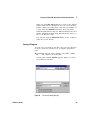
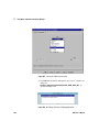
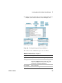
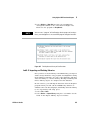
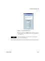
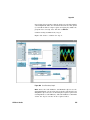
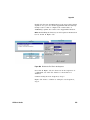
Figure 3. Using the Help Menu
......................................................
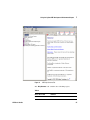
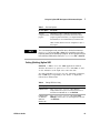
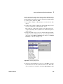
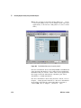
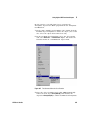
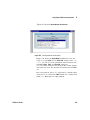
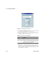
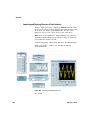
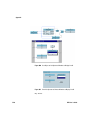
Figure 4. VEE Help Contents Tab . . . . . . . . . . . . . . . . . . . . . . . . . . . . . . . . . . . . . . . . . . . . . . . . . . . . .
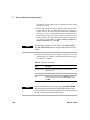
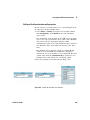
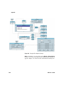
Figure 5. Adding Objects to the Work Area . . . . . . . . . . . . . . . . . . . . . . . . . . . . . . . . . . . . . . . . . . . .
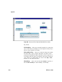
Figure 6. Adding a Function Generator Object
.........................................
Figure 7. Object in Open View and Icon View . . . . . . . . . . . . . . . . . . . . . . . . . . . . . . . . . . . . . . . . . .
Figure 8. Selecting an Object Menu . . . . . . . . . . . . . . . . . . . . . . . . . . . . . . . . . . . . . . . . . . . . . . . . . . . . .
Figure 9. Moving an Object
.........................................................
Figure 10. Cloning an Object
........................................................
Figure 11. Changing the Size of an Object. . . . . . . . . . . . . . . . . . . . . . . . . . . . . . . . . . . . . . . . . . . . . . . .
Figure 12. Changing the Title of an Object
............................................
Figure 13. Selected and Deselected Objects . . . . . . . . . . . . . . . . . . . . . . . . . . . . . . . . . . . . . . . . . . .
Figure 14. Multiple Objects during Copying . . . . . . . . . . . . . . . . . . . . . . . . . . . . . . . . . . . . . . . . . . . .
Figure 15. Creating Data Lines Between Objects . . . . . . . . . . . . . . . . . . . . . . . . . . . . . . . . . . . . . . .
Figure 16. Scroll Bars in Work Area
..................................................
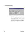
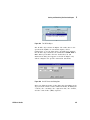
Figure 17. Default Preferences Dialog Box
............................................
Figure 18. Data and Sequence Pins
..................................................
Figure 19. Show Terminals on an Object
..............................................
Figure 20. Setting the ShowTerminals Property . . . . . . . . . . . . . . . . . . . . . . . . . . . . . . . . . . . . . . . .
Figure 21. Adding a Terminal . . . . . . . . . . . . . . . . . . . . . . . . . . . . . . . . . . . . . . . . . . . . . . . . . . . . . . . .
Figure 22. Obtaining Terminal Information
............................................
Figure 23. Using the Selection Field . . . . . . . . . . . . . . . . . . . . . . . . . . . . . . . . . . . . . . . . . . . . . . . . . .
Figure 24. Delete Terminal Dialog Box . . . . . . . . . . . . . . . . . . . . . . . . . . . . . . . . . . . . . . . . . . . . . . . .
Figure 25. Creating a Program . . . . . . . . . . . . . . . . . . . . . . . . . . . . . . . . . . . . . . . . . . . . . . . . . . . . . . .
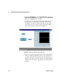
Figure 26. Running a Program . . . . . . . . . . . . . . . . . . . . . . . . . . . . . . . . . . . . . . . . . . . . . . . . . . . . . . .
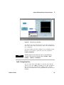
Figure 27. Changing the Function Field to Sine Wave . . . . . . . . . . . . . . . . . . . . . . . . . . . . . . . . . . .
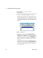
Figure 28. Highlighting a Frequency Field Number
.....................................
Figure 29. Example: Changing the Frequency Field to 10 Hz
.............................
Figure 30. Printing the Screen . . . . . . . . . . . . . . . . . . . . . . . . . . . . . . . . . . . . . . . . . . . . . . . . . . . . . . .
VEE User’s Guide
23
25
26
27
30
31
32
33
34
35
37
38
39
40
42
43
45
46
47
48
49
49
50
51
53
54
56
57
57
58
1
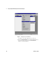
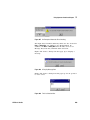
Figure 31. The Save File Dialog Box (PC) . . . . . . . . . . . . . . . . . . . . . . . . . . . . . . . . . . . . . . . . . . . . . . 59
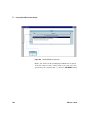
Figure 32. The Run button on the Tool Bar
. . . . . . . . . . . . . . . . . . . . . . . . . . . . . . . . . . . . . . . . . . . . 62
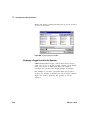
Figure 33. Multiple windows in the Work Area
. . . . . . . . . . . . . . . . . . . . . . . . . . . . . . . . . . . . . . . . 63
Figure 34. Typical simple-program.vee Display
. . . . . . . . . . . . . . . . . . . . . . . . . . . . . . . . . . . . . . . . . 66
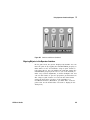
Figure 35. Example: Adding a Noise Generator Object . . . . . . . . . . . . . . . . . . . . . . . . . . . . . . . . . . . 67
Figure 36. Function and Object Browser
. . . . . . . . . . . . . . . . . . . . . . . . . . . . . . . . . . . . . . . . . . . . . . 68
Figure 37. Example: Adding Input Terminals . . . . . . . . . . . . . . . . . . . . . . . . . . . . . . . . . . . . . . . . . . . 69
Figure 38. Example: Adding a Real64 Slider Object
. . . . . . . . . . . . . . . . . . . . . . . . . . . . . . . . . . . . . 70
Figure 39. Displaying the Value on an Output Pin . . . . . . . . . . . . . . . . . . . . . . . . . . . . . . . . . . . . . . . 71
Figure 40. UserObject Window
. . . . . . . . . . . . . . . . . . . . . . . . . . . . . . . . . . . . . . . . . . . . . . . . . . . . . . 77
Figure 41. usrobj-program.vee at an Early Stage
. . . . . . . . . . . . . . . . . . . . . . . . . . . . . . . . . . . . . . . 79
Figure 42. Creating a UserObject
. . . . . . . . . . . . . . . . . . . . . . . . . . . . . . . . . . . . . . . . . . . . . . . . . . . . 80
Figure 43. UserObject Renamed AddNoise . . . . . . . . . . . . . . . . . . . . . . . . . . . . . . . . . . . . . . . . . . . . 82
Figure 44. Noisy Cosine Wave . . . . . . . . . . . . . . . . . . . . . . . . . . . . . . . . . . . . . . . . . . . . . . . . . . . . . . . 82
Figure 45. The Int32 Input Configuration Box
. . . . . . . . . . . . . . . . . . . . . . . . . . . . . . . . . . . . . . . . . . 83
Figure 46. Int32 Input Added to usrobj-program.vee
. . . . . . . . . . . . . . . . . . . . . . . . . . . . . . . . . . . . 84
Figure 47. Runtime Pop-Up Input Box
. . . . . . . . . . . . . . . . . . . . . . . . . . . . . . . . . . . . . . . . . . . . . . . . 85
Figure 48. Adding a Data File . . . . . . . . . . . . . . . . . . . . . . . . . . . . . . . . . . . . . . . . . . . . . . . . . . . . . . . . 86
Figure 49. Choosing an I/O Transaction
. . . . . . . . . . . . . . . . . . . . . . . . . . . . . . . . . . . . . . . . . . . . . . 87
Figure 50. Adding a To File Object . . . . . . . . . . . . . . . . . . . . . . . . . . . . . . . . . . . . . . . . . . . . . . . . . . . . 88
Figure 51. Adding a From File Object
. . . . . . . . . . . . . . . . . . . . . . . . . . . . . . . . . . . . . . . . . . . . . . . . . 89
Figure 52. simple-program.vee . . . . . . . . . . . . . . . . . . . . . . . . . . . . . . . . . . . . . . . . . . . . . . . . . . . . . . . 90
Figure 53. Example: Creating a Panel View . . . . . . . . . . . . . . . . . . . . . . . . . . . . . . . . . . . . . . . . . . . . 91
Figure 54. Using Data Types . . . . . . . . . . . . . . . . . . . . . . . . . . . . . . . . . . . . . . . . . . . . . . . . . . . . . . . . . 93
Figure 55. Connecting Data Objects
. . . . . . . . . . . . . . . . . . . . . . . . . . . . . . . . . . . . . . . . . . . . . . . . . 94
Figure 56. Creating a Formula Object Program . . . . . . . . . . . . . . . . . . . . . . . . . . . . . . . . . . . . . . . . . 96
Figure 57. Show Data Flow
. . . . . . . . . . . . . . . . . . . . . . . . . . . . . . . . . . . . . . . . . . . . . . . . . . . . . . . . 100
Figure 58. Data Flow in simple-program.vee . . . . . . . . . . . . . . . . . . . . . . . . . . . . . . . . . . . . . . . . . . 101
Figure 59. Show Execution Flow . . . . . . . . . . . . . . . . . . . . . . . . . . . . . . . . . . . . . . . . . . . . . . . . . . . . 102
Figure 60. Displaying the Value on an Output Pin
. . . . . . . . . . . . . . . . . . . . . . . . . . . . . . . . . . . . . 103
Figure 61. Displaying Information about a Line
. . . . . . . . . . . . . . . . . . . . . . . . . . . . . . . . . . . . . . . 104
Figure 62. Set Breakpoint(s)
. . . . . . . . . . . . . . . . . . . . . . . . . . . . . . . . . . . . . . . . . . . . . . . . . . . . . . . 105
Figure 63. Resume Program (same as the Run Button)
. . . . . . . . . . . . . . . . . . . . . . . . . . . . . . . . 106
2
VEE User’s Guide
Figure 64. Clear Breakpoint(s) . . . . . . . . . . . . . . . . . . . . . . . . . . . . . . . . . . . . . . . . . . . . . . . . . . . . . .
Figure 65. Pause or Stop a Program . . . . . . . . . . . . . . . . . . . . . . . . . . . . . . . . . . . . . . . . . . . . . . . . .
Figure 66. Example Runtime Error Message using Go To
...............................
Figure 67. Using the Call Stack in Wheel.exe . . . . . . . . . . . . . . . . . . . . . . . . . . . . . . . . . . . . . . . . .
Figure 68. The Order of Events in an Object
..........................................
Figure 69. Control Line Used to Execute Custom Title
.................................
Figure 70. Start Objects Executing Separate Threads . . . . . . . . . . . . . . . . . . . . . . . . . . . . . . . . . .
Figure 71. Step Into, Step Over, and Step Out Buttons on the Toolbar
....................
Figure 72. The Random Program . . . . . . . . . . . . . . . . . . . . . . . . . . . . . . . . . . . . . . . . . . . . . . . . . . . .
Figure 73. Set and Get a Global Variable
.............................................
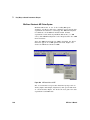
Figure 74. The Description Dialog Box . . . . . . . . . . . . . . . . . . . . . . . . . . . . . . . . . . . . . . . . . . . . . . .
Figure 75. The Beginning of the Documentation File . . . . . . . . . . . . . . . . . . . . . . . . . . . . . . . . . . .
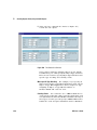
Figure 76. The Middle of the Documentation File
.....................................
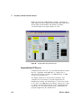
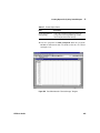
Figure 77. The Remainder of the Documentation File . . . . . . . . . . . . . . . . . . . . . . . . . . . . . . . . . . .
Figure 78. The HP54600A Scope Panel Driver
........................................
Figure 79. A Function Generator Direct I/O Object
....................................
Figure 80. Importing a PC Plug-In Library
............................................
Figure 81. Calls to a VXIplug&play Driver from VEE . . . . . . . . . . . . . . . . . . . . . . . . . . . . . . . . . . . .
Figure 82. The Instrument Manager Box . . . . . . . . . . . . . . . . . . . . . . . . . . . . . . . . . . . . . . . . . . . . .
Figure 83. Instrument Properties Dialog Box . . . . . . . . . . . . . . . . . . . . . . . . . . . . . . . . . . . . . . . . . .
Figure 84. The Advanced Instrument Properties Dialog . . . . . . . . . . . . . . . . . . . . . . . . . . . . . . . . .
Figure 85. The Panel Driver Folder
..................................................
Figure 86. Scope Added to List of Instruments
.......................................
Figure 87. Selecting scope(@(NOT LIVE)) . . . . . . . . . . . . . . . . . . . . . . . . . . . . . . . . . . . . . . . . . . . .
Figure 88. The Function Pop-up Menu on fgen . . . . . . . . . . . . . . . . . . . . . . . . . . . . . . . . . . . . . . . .
Figure 89. Sweep Panel in Discrete Component Menu . . . . . . . . . . . . . . . . . . . . . . . . . . . . . . . . .
Figure 90. The Data Input and Output Areas on a Driver . . . . . . . . . . . . . . . . . . . . . . . . . . . . . . . .
Figure 91. The Direct I/O Configuration Folder . . . . . . . . . . . . . . . . . . . . . . . . . . . . . . . . . . . . . . . .
Figure 92. A Direct I/O Object . . . . . . . . . . . . . . . . . . . . . . . . . . . . . . . . . . . . . . . . . . . . . . . . . . . . . .
Figure 93. The I/O Transaction Dialog Box . . . . . . . . . . . . . . . . . . . . . . . . . . . . . . . . . . . . . . . . . . . .
Figure 94. A Direct I/O Transaction
.................................................
Figure 95. Direct I/O Setup Using an Input Variable . . . . . . . . . . . . . . . . . . . . . . . . . . . . . . . . . . . .
Figure 96. Configuring a READ Transaction
..........................................
VEE User’s Guide
106
107
108
109
110
112
112
113
116
118
119
121
122
123
130
130
131
132
133
134
136
137
139
140
143
144
145
147
148
149
150
151
154
3
Figure 97. Direct I/O Configured to Read a Measurement . . . . . . . . . . . . . . . . . . . . . . . . . . . . . .
Figure 98. Learn String Configuration for HP54100A . . . . . . . . . . . . . . . . . . . . . . . . . . . . . . . . . . .
Figure 99. Amplicon Data Acquisition Example
.......................................
Figure 100. VEE Using a ComputerBoards 100 KHz Board . . . . . . . . . . . . . . . . . . . . . . . . . . . . . . . .
Figure 101. Importing the ComputerBoards I/O Library
................................
Figure 102. ME Board Menu in VEE
.................................................
Figure 103. User Panel for Data Acquisition Board ME-3000
...........................
Figure 104. Function Panel for ME-DriverSystem . . . . . . . . . . . . . . . . . . . . . . . . . . . . . . . . . . . . . .
Figure 105. Selecting a VXIplug&play Driver . . . . . . . . . . . . . . . . . . . . . . . . . . . . . . . . . . . . . . . . . .
Figure 106. Selecting a Function for a VXIplug&play Driver . . . . . . . . . . . . . . . . . . . . . . . . . . . . .
Figure 107. The hpe1412 Edit Function Panel . . . . . . . . . . . . . . . . . . . . . . . . . . . . . . . . . . . . . . . . .
Figure 108. DC Voltage Function in VXIplug&play Object . . . . . . . . . . . . . . . . . . . . . . . . . . . . . . .
Figure 109. Configuration Folder in Edit Function Panel . . . . . . . . . . . . . . . . . . . . . . . . . . . . . . . .
Figure 110. HPE1412 Driver Ready for a DC Reading . . . . . . . . . . . . . . . . . . . . . . . . . . . . . . . . . . .
Figure 111. A VEE Function in the Function & Object Browser
..........................
Figure 112. A MATLAB Function in the Function & Object Browser . . . . . . . . . . . . . . . . . . . . . .
Figure 113. Opening Function and Object Browser from fx Icon . . . . . . . . . . . . . . . . . . . . . . . . .
Figure 114. Calculating Standard Deviation
..........................................
Figure 115. The Formula Object . . . . . . . . . . . . . . . . . . . . . . . . . . . . . . . . . . . . . . . . . . . . . . . . . . . . .
Figure 116. Evaluating an Expression
...............................................
Figure 117. Formula Examples Using VEE Functions . . . . . . . . . . . . . . . . . . . . . . . . . . . . . . . . . . .
Figure 118. VEE Functions Using One Formula Object
.................................
Figure 119. On Your Own Solution: Ramp and SDEV
...................................
Figure 120. MATLAB Script Object in a VEE Program . . . . . . . . . . . . . . . . . . . . . . . . . . . . . . . . . .
Figure 121. Graph Generated by the Program . . . . . . . . . . . . . . . . . . . . . . . . . . . . . . . . . . . . . . . . .
Figure 122. Adding Predefined MATLAB Objects to a VEE Program
.....................
Figure 123. Changing Input Terminal Data Type
.......................................
Figure 124. Displaying a Waveform
.................................................
Figure 125. Delta Markers on a Waveform Display
....................................
Figure 126. The Collector Creating an Array
..........................................
Figure 127. Extracting Array Elements with Expressions
..............................
Figure 128. The To File Object
......................................................
Figure 129. An I/O Transaction Dialog Box . . . . . . . . . . . . . . . . . . . . . . . . . . . . . . . . . . . . . . . . . . .
4
154
156
158
159
159
160
161
162
164
165
166
166
167
167
178
179
180
181
182
184
185
186
187
189
190
192
194
198
199
208
209
211
211
VEE User’s Guide
Figure 130. The TIME STAMP I/O Transaction Box . . . . . . . . . . . . . . . . . . . . . . . . . . . . . . . . . . . .
Figure 131. Storing Data Using the To File Object . . . . . . . . . . . . . . . . . . . . . . . . . . . . . . . . . . . . . .
Figure 132. Selecting String Format . . . . . . . . . . . . . . . . . . . . . . . . . . . . . . . . . . . . . . . . . . . . . . . . .
Figure 133. Retrieving Data Using the From File Object . . . . . . . . . . . . . . . . . . . . . . . . . . . . . . . . .
Figure 134. Output Terminal Information on a Record . . . . . . . . . . . . . . . . . . . . . . . . . . . . . . . . . .
Figure 135. The AlphaNumeric Properties Box . . . . . . . . . . . . . . . . . . . . . . . . . . . . . . . . . . . . . . . .
Figure 136. Using the Get Field Object . . . . . . . . . . . . . . . . . . . . . . . . . . . . . . . . . . . . . . . . . . . . . . .
Figure 137. Using the Set Field Object . . . . . . . . . . . . . . . . . . . . . . . . . . . . . . . . . . . . . . . . . . . . . . .
Figure 138. Using the UnBuild Record Object . . . . . . . . . . . . . . . . . . . . . . . . . . . . . . . . . . . . . . . . .
Figure 139. Storing an Array of Records in a DataSet
..................................
Figure 140. Storing and Retrieving Data Using DataSets . . . . . . . . . . . . . . . . . . . . . . . . . . . . . . . .
Figure 141. A Search Operation with DataSets . . . . . . . . . . . . . . . . . . . . . . . . . . . . . . . . . . . . . . . .
Figure 142. Adding the Test Menu object
............................................
Figure 143. Adding a Menu to the Search Operation . . . . . . . . . . . . . . . . . . . . . . . . . . . . . . . . . . .
Figure 144. The Operator Interface for the Database . . . . . . . . . . . . . . . . . . . . . . . . . . . . . . . . . . .
Figure 145. A Sort Operation on a Record Field
.......................................
Figure 146. The ActiveX Automation Reference Box . . . . . . . . . . . . . . . . . . . . . . . . . . . . . . . . . . .
Figure 147. Example of Data Type “Object”
..........................................
Figure 148. Commands to Set Up Excel Worksheet to Display Test Reults
................
Figure 149. CreateObject and GetObject
.............................................
Figure 150. The Globals UserFunction
...............................................
Figure 151. Setting Up the MS Excel Worksheet
.....................................
Figure 152. Adding the Title and Data to the Sheet . . . . . . . . . . . . . . . . . . . . . . . . . . . . . . . . . . . .
Figure 153. The Results Average Program . . . . . . . . . . . . . . . . . . . . . . . . . . . . . . . . . . . . . . . . . . . .
Figure 154. Excel Worksheet for “Results Average” Program . . . . . . . . . . . . . . . . . . . . . . . . . . .
Figure 155. Excel Worksheet for Array of Test Data
...................................
Figure 156. Program for Array of Test Data . . . . . . . . . . . . . . . . . . . . . . . . . . . . . . . . . . . . . . . . . . .
Figure 157. Program for On Your Own Exercise
.......................................
Figure 158. A VEE to MS Excel Program Example
.....................................
Figure 159. Object Variables . . . . . . . . . . . . . . . . . . . . . . . . . . . . . . . . . . . . . . . . . . . . . . . . . . . . . . . .
Figure 160. Beginning of Lab 6-3 Program
...........................................
Figure 161. Adding the ActiveX Statements . . . . . . . . . . . . . . . . . . . . . . . . . . . . . . . . . . . . . . . . . .
Figure 162. The Complete Program for Report in MS Word . . . . . . . . . . . . . . . . . . . . . . . . . . . . . .
VEE User’s Guide
217
218
219
221
224
226
227
229
231
234
236
238
240
242
243
245
251
252
253
254
256
257
260
262
263
265
266
267
268
271
272
273
275
5
Figure 163. The MS Word Document Created by Lab 6-3
...............................
Figure 164. Import Namespaces Dialog Box . . . . . . . . . . . . . . . . . . . . . . . . . . . . . . . . . . . . . . . . . .
Figure 165. Function & Object Browser - .NET Objects . . . . . . . . . . . . . . . . . . . . . . . . . . . . . . . . .
Figure 166. Creating a .NET Object . . . . . . . . . . . . . . . . . . . . . . . . . . . . . . . . . . . . . . . . . . . . . . . . . .
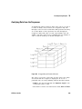
Figure 167. Assemblies, Namespaces, Types, and Members
...........................
Figure 168. .NET Assembly References - Importing Namespaces
.......................
Figure 169. Namespaces Selection List . . . . . . . . . . . . . . . . . . . . . . . . . . . . . . . . . . . . . . . . . . . . . .
Figure 170. Creating a .NET Object and Accessing Its Instance Member
.................
Figure 171. Static Method without Namespace Imported
..............................
Figure 172. Static Method with an Imported Namespace
..............................
Figure 173. Function & Object Browser Creating an Instance
...........................
Figure 174. openFileDialog Program . . . . . . . . . . . . . . . . . . . . . . . . . . . . . . . . . . . . . . . . . . . . . . . . .
Figure 175. Step 10 of Lab 7-2 . . . . . . . . . . . . . . . . . . . . . . . . . . . . . . . . . . . . . . . . . . . . . . . . . . . . . .
Figure 176. Lab 7-2 Completed
.....................................................
Figure 177. Completed Lab 7-3
.....................................................
Figure 178. The Execute Program Object (PC)
........................................
Figure 179. Listing the Files in a Directory
...........................................
Figure 180. System Information Functions
...........................................
Figure 181. The Main and ArrayStats Windows . . . . . . . . . . . . . . . . . . . . . . . . . . . . . . . . . . . . . . .
Figure 182. Configuring the Pins for Call myFunction
..................................
Figure 183. Calling the User Function ArrayStats
.....................................
Figure 184. Editing the UserFunction ArrayStats . . . . . . . . . . . . . . . . . . . . . . . . . . . . . . . . . . . . . .
Figure 185. After Editing ArrayStats Output to a Record
...............................
Figure 186. Calling the ArrayStats User Function
.....................................
Figure 187. The Generate Menu in a UserFunction
....................................
Figure 188. Generating a Call Object ArrayStats(A) from a UserFunction
.................
Figure 189. Program Explorer Icon on the Toolbar
.....................................
Figure 190. Using the Program Explorer with UserFunctions . . . . . . . . . . . . . . . . . . . . . . . . . . . .
Figure 191. Report.vee from the Top Level . . . . . . . . . . . . . . . . . . . . . . . . . . . . . . . . . . . . . . . . . . . .
Figure 192. The BuildRecAry UserFunction . . . . . . . . . . . . . . . . . . . . . . . . . . . . . . . . . . . . . . . . . . .
Figure 193. The ReportHeader UserFunction
.........................................
Figure 194. The ReportBody UserFunction
...........................................
Figure 195. The ReportDisplay Detail View
...........................................
6
276
283
286
287
289
290
291
300
301
301
303
305
307
308
310
322
325
326
335
335
336
337
338
339
341
342
343
343
345
346
347
348
349
VEE User’s Guide
Figure 196. The ReportDisplay Panel View
...........................................
Figure 197. The RepGen.vee Library of UserFunctions
.................................
Figure 198. Selecting a Function from an Imported Library
.............................
Figure 199. Calling a Function from a Library
.........................................
Figure 200. The Find Dialog Box
....................................................
Figure 201. The Find Results Dialog Box
.............................................
Figure 202. Merging the BarChart Program
..........................................
Figure 203. The Sequence Transaction Dialog Box
....................................
Figure 204. Configuring a Test . . . . . . . . . . . . . . . . . . . . . . . . . . . . . . . . . . . . . . . . . . . . . . . . . . . . . .
Figure 205. A Simple Sequencer Example . . . . . . . . . . . . . . . . . . . . . . . . . . . . . . . . . . . . . . . . . . . .
Figure 206. A Logged Record or Records . . . . . . . . . . . . . . . . . . . . . . . . . . . . . . . . . . . . . . . . . . . . .
Figure 207. Accessing Logged Data . . . . . . . . . . . . . . . . . . . . . . . . . . . . . . . . . . . . . . . . . . . . . . . . .
Figure 208. The Rand UserFunction
.................................................
Figure 209. Passing Data Using an Input Terminal . . . . . . . . . . . . . . . . . . . . . . . . . . . . . . . . . . . . .
Figure 210. The Global UserFunction (Detail)
.........................................
Figure 211. The Global UserFunction (Panel)
.........................................
Figure 212. Passing data Using a Global Variable
.....................................
Figure 213. The noisyWv UserFunction (Detail)
.......................................
Figure 214. The noisyWv UserObject (Panel)
.........................................
Figure 215. Comparing a Waveform to a Mask . . . . . . . . . . . . . . . . . . . . . . . . . . . . . . . . . . . . . . . .
Figure 216. A Logged Array of Records of Records
....................................
Figure 217. Analyzing Several Runs of Sequencer Data
................................
Figure 218. Storing Logged Data with To/From File
...................................
Figure 219. Storing Logged Data with To/From DataSet
...............................
Figure 220. Panel View Button and Detail View Button in Title Bar . . . . . . . . . . . . . . . . . . . . . .
Figure 221. A Selection of VEE Indicators . . . . . . . . . . . . . . . . . . . . . . . . . . . . . . . . . . . . . . . . . . . .
Figure 222. Background Picture Used as Tile
........................................
Figure 223. A Cropped Image in VEE
................................................
Figure 224. Controls from Various Data Submenus . . . . . . . . . . . . . . . . . . . . . . . . . . . . . . . . . . . .
Figure 225. The Properties Dialog Box . . . . . . . . . . . . . . . . . . . . . . . . . . . . . . . . . . . . . . . . . . . . . . .
Figure 226. A Text Input Box
.......................................................
Figure 227. An Example of Automatic Error Checking . . . . . . . . . . . . . . . . . . . . . . . . . . . . . . . . . .
Figure 228. A Pop-Up Message Box . . . . . . . . . . . . . . . . . . . . . . . . . . . . . . . . . . . . . . . . . . . . . . . . .
VEE User’s Guide
350
351
353
354
356
357
359
367
368
374
375
376
378
380
382
383
384
385
386
388
389
391
394
395
401
402
404
405
406
408
408
409
409
7
Figure 229. The List Selection Box
..................................................
Figure 230. A Pop-Up File Selection Box . . . . . . . . . . . . . . . . . . . . . . . . . . . . . . . . . . . . . . . . . . . . .
Figure 231. Switches and Alarms Combined . . . . . . . . . . . . . . . . . . . . . . . . . . . . . . . . . . . . . . . . . .
Figure 232. Configuring Panel Properties
............................................
Figure 233. A Softkey Executing a UserFunction
......................................
Figure 234. Configuring the Confirm (OK) Object as a Softkey . . . . . . . . . . . . . . . . . . . . . . . . . . .
Figure 235. The Default Preferences Dialog Box
......................................
Figure 236. Color Selection for Screen Elements . . . . . . . . . . . . . . . . . . . . . . . . . . . . . . . . . . . . . .
Figure 237. Creating a Status Panel
.................................................
Figure 238. Early Stage in the Dice Program . . . . . . . . . . . . . . . . . . . . . . . . . . . . . . . . . . . . . . . . . .
Figure 239. The Dice Program (Detail View)
..........................................
Figure 240. The Dice Program (Panel View)
..........................................
Figure 241. The Bitmap Function
...................................................
Figure 242. The UserFunction alarm (Detail View) . . . . . . . . . . . . . . . . . . . . . . . . . . . . . . . . . . . . .
Figure 243. The Warning UserFunction (Detail View) . . . . . . . . . . . . . . . . . . . . . . . . . . . . . . . . . . .
Figure 244. The Warning Program
..................................................
Figure 245. Using the ActiveX Control “ProgressBar”
.................................
Figure 246. An ActiveX Control Example Using MSChart . . . . . . . . . . . . . . . . . . . . . . . . . . . . . . .
Figure 247. Configuring Test1
......................................................
Figure 248. The UserFunction LogTest (Detail) . . . . . . . . . . . . . . . . . . . . . . . . . . . . . . . . . . . . . . . .
Figure 249. The UserFunction LogTest (Panel)
........................................
Figure 250. Status Panel Program (before running) . . . . . . . . . . . . . . . . . . . . . . . . . . . . . . . . . . . .
Figure 251. The Status Panel Program (running)
......................................
Figure 252. Calculating Square Roots per Measurement
...............................
Figure 253. Calculating Square Roots using Math Array
...............................
Figure 254. Optimizing Programs by Using Icons . . . . . . . . . . . . . . . . . . . . . . . . . . . . . . . . . . . . . .
Figure 255. Function Calls without Optimization
......................................
Figure 256. Function Calls with Optimization
.........................................
Figure 257. Importing a Library of Compiled Functions . . . . . . . . . . . . . . . . . . . . . . . . . . . . . . . . .
Figure 258. Using Call Object for Compiled Functions . . . . . . . . . . . . . . . . . . . . . . . . . . . . . . . . . .
Figure 259. A Program Using a DLL (MANUAL49) . . . . . . . . . . . . . . . . . . . . . . . . . . . . . . . . . . . . .
Figure 260. The Shared Library Name UserObject
.....................................
Figure 261. Execution Mode Display in VEE Status Bar
................................
8
409
410
411
412
413
414
415
416
418
421
423
424
426
428
430
432
433
434
435
436
437
437
438
444
445
446
447
448
453
454
456
458
461
VEE User’s Guide
Figure 262. Changing the Execution Mode in Default Preferences . . . . . . . . . . . . . . . . . . . . . . .
Figure 263. Chaos.vee in VEE 3 Mode with Open Displays . . . . . . . . . . . . . . . . . . . . . . . . . . . . . .
Figure 264. Chaos.vee in VEE 3 Mode with Closed Displays . . . . . . . . . . . . . . . . . . . . . . . . . . . . .
Figure 265. Chaos.vee in VEE 4 or Higher Mode with Debugging Disabled . . . . . . . . . . . . . . . .
Figure 266. Iterative Math Example in VEE 3 Mode . . . . . . . . . . . . . . . . . . . . . . . . . . . . . . . . . . . .
Figure 267. Iterative Math Example Using VEE 4 or Higher Mode . . . . . . . . . . . . . . . . . . . . . . . .
Figure 268. An Example of the Profiler . . . . . . . . . . . . . . . . . . . . . . . . . . . . . . . . . . . . . . . . . . . . . . .
Figure 269. Model of Web Measurement Application . . . . . . . . . . . . . . . . . . . . . . . . . . . . . . . . . .
Figure 270. A Scripting Language Host Model . . . . . . . . . . . . . . . . . . . . . . . . . . . . . . . . . . . . . . . .
Figure 271. The Default Preferences Web Server Dialog Box
...........................
Figure 272. The Index.html Default Page . . . . . . . . . . . . . . . . . . . . . . . . . . . . . . . . . . . . . . . . . . . . .
Figure 273. Viewing the Main Solitaire.vee Program in the Browser
.....................
Figure 274. Displaying a VEE Error Message, using the Browser . . . . . . . . . . . . . . . . . . . . . . . . .
Figure 275. Detail View of a UserFunction Displayed in the Browser . . . . . . . . . . . . . . . . . . . . .
Figure 276. Example of Displaying HTML Message Instead of VEE Program
..............
Figure 277. An Example of a Password Window
......................................
Figure 278. Apple Bagger, Solution 1 . . . . . . . . . . . . . . . . . . . . . . . . . . . . . . . . . . . . . . . . . . . . . . . .
Figure 279. Apple Bagger, Solution 2
...............................................
Figure 280. Testing Numbers (pop-up shown) . . . . . . . . . . . . . . . . . . . . . . . . . . . . . . . . . . . . . . . .
Figure 281. Testing Numbers, Step 2
................................................
Figure 282. Testing Numbers, Step 3
................................................
Figure 283. Collecting Random Numbers
............................................
Figure 284. Random Number Generator, Step 1 . . . . . . . . . . . . . . . . . . . . . . . . . . . . . . . . . . . . . . .
Figure 285. Random Number Generator, Step 2 . . . . . . . . . . . . . . . . . . . . . . . . . . . . . . . . . . . . . . .
Figure 286. The Mask Test, Step 1
..................................................
Figure 287. Mask Test, Step 2
......................................................
Figure 288. Manipulating Strings and Global Variables
................................
Figure 289. Optimizing VEE Programs, Step 1 . . . . . . . . . . . . . . . . . . . . . . . . . . . . . . . . . . . . . . . . .
Figure 290. Optimizing VEE Programs, Step 2 . . . . . . . . . . . . . . . . . . . . . . . . . . . . . . . . . . . . . . . . .
Figure 291. A Random Noise UserObject
............................................
Figure 292. The NoiseGen UserObject . . . . . . . . . . . . . . . . . . . . . . . . . . . . . . . . . . . . . . . . . . . . . . .
Figure 293. User Functions, Step 1 . . . . . . . . . . . . . . . . . . . . . . . . . . . . . . . . . . . . . . . . . . . . . . . . . .
Figure 294. User Functions, Step 2 . . . . . . . . . . . . . . . . . . . . . . . . . . . . . . . . . . . . . . . . . . . . . . . . . .
VEE User’s Guide
463
464
465
466
467
467
469
475
477
481
487
489
490
491
493
494
500
501
503
504
505
507
508
509
511
512
514
516
517
519
520
522
523
9
Figure 295. User Functions, Step 3 . . . . . . . . . . . . . . . . . . . . . . . . . . . . . . . . . . . . . . . . . . . . . . . . . .
Figure 296. User Functions, Step 4 . . . . . . . . . . . . . . . . . . . . . . . . . . . . . . . . . . . . . . . . . . . . . . . . . .
Figure 297. Importing and Deleting Libraries
.........................................
Figure 298. UserObject to Ask Operator to Input A and B
..............................
Figure 299. Panel for Operator to Enter A and B . . . . . . . . . . . . . . . . . . . . . . . . . . . . . . . . . . . . . . .
Figure 300. UserObject to Ask Operator Whether to Display A or B . . . . . . . . . . . . . . . . . . . . . .
Figure 301. Panel for Operator to Choose Whether to Display A or B . . . . . . . . . . . . . . . . . . . . .
Figure 302. Generate an Error if Operator Does Not Enter a Choice . . . . . . . . . . . . . . . . . . . . . .
Figure 303. Moving Data To and From Files
..........................................
Figure 304. Manipulating Records, Step 1 . . . . . . . . . . . . . . . . . . . . . . . . . . . . . . . . . . . . . . . . . . . .
Figure 305. Manipulating Records, Step 2 . . . . . . . . . . . . . . . . . . . . . . . . . . . . . . . . . . . . . . . . . . . .
Figure 306. Manipulating Records, Step 3 . . . . . . . . . . . . . . . . . . . . . . . . . . . . . . . . . . . . . . . . . . . .
Figure 307. Using the Test Sequencer, Step 1 . . . . . . . . . . . . . . . . . . . . . . . . . . . . . . . . . . . . . . . . .
Figure 308. Disable the First Test in the Sequence
....................................
Figure 309. Using the Test Sequencer, Step 2 . . . . . . . . . . . . . . . . . . . . . . . . . . . . . . . . . . . . . . . . .
Figure 310. Using the Test Sequencer, Step 3
........................................
Figure 311. Add a Time Stamp to the Logging Record . . . . . . . . . . . . . . . . . . . . . . . . . . . . . . . . . .
Figure 312. Using the Test Sequencer, Step 4
........................................
Figure 313. Checking a Record
.....................................................
Figure 314. Using the Test Sequencer, Step 5 . . . . . . . . . . . . . . . . . . . . . . . . . . . . . . . . . . . . . . . . .
Figure 315. Using the Test Sequencer, Step 6 . . . . . . . . . . . . . . . . . . . . . . . . . . . . . . . . . . . . . . . . .
Figure 316. Using the Test Sequencer, Step 7
........................................
Figure 317. Using the Test Sequencer, Step 8 . . . . . . . . . . . . . . . . . . . . . . . . . . . . . . . . . . . . . . . . .
10
524
525
526
528
529
530
530
532
533
536
538
539
542
543
544
545
547
548
549
550
551
552
553
VEE User’s Guide
Introduction
Overview of Agilent VEE 3
Installing and Learning About Agilent VEE 11
MATLAB Script Overview 14
Obtaining Agilent VEE Support 16
Sources of Additional Information for MATLAB 17
VEE Pro User’s Guide
1
Introduction
Introduction
This chapter introduces Agilent VEE and its major features. You
also learn how to install and learn about VEE, and how to
obtain VEE support.
2
VEE Pro User’s Guide
Introduction
Overview of Agilent VEE
Agilent VEE is a graphical programming language optimized for
building test and measurement applications, and programs with
operator interfaces. This release (version 7.0) of the Agilent
VEE product is for groups of engineers that need to create
complex test and measurement systems.
Advantages of Using Agilent VEE for Test Development
VEE offers many advantages in test development:
• Increase your productivity dramatically. Customers report
reducing their program development time up to 80%.
• Use VEE in a wide range of applications including functional
test, design verification, calibration, and data acquisition and
control.
• Gain instrument I/O flexibility controlling GPIB, VXI, Serial,
GPIO, PC Plug- in cards, and LAN instruments. Use “panel”
drivers, VXIplug&play drivers, “direct I/O” over standard
interfaces, or imported libraries from multiple vendors.
• Use ActiveX Automation and Controls on PCs to control
other applications such as MS Word, Excel, and Access that
assist with generating reports, displaying and analyzing data,
or putting test results into a database for future use.
• Increase throughput, build larger programs with ease, and
become more flexible in instrument management. VEE has a
compiler; a professional development environment suited for
large, complex programs; and advanced instrument
management capabilities.
• VEE supports Visual Studio .NET assembles, which means
that any textual language that truly supports Visual Studio
.NET is supported by VEE.
• You can further leverage your investment in textual
languages because VEE also supports additional textual
languages such as C/C++, Visual Basic, Pascal, and Fortran.
VEE Pro User’s Guide
3
Introduction
VEE programs are created by selecting objects from menus and
connecting them together. The result in VEE resembles a data
flow diagram, which is easier to use and understand than
traditional lines of code. There is no laborious
edit- compile- link- execute cycle using VEE.
The following two figures compare a simple function
programmed first in a textual language (ANSI C) and then in
VEE. In both cases, the function creates an array of 10 random
numbers, finds the maximum value, and displays the array and
maximum value.
Figure I- 1 shows the program, called “Random,” in the ANSI
C textual language.
4
VEE Pro User’s Guide
Introduction
/* Program to find maximum element in array */
#include <math.h>
main( )
{
double num[10],max;
int i;
for (i=0;i<10;i++){
num[i]=(double) rand( )/pow(2.0,15.0);
printf("%f/n",num[i];
}
max=num[0];
for {i=1;i<10;i++){
if (num[i]>max)max=num[i];
}
printf("/nmax; %f/n",max);
}
Figure I-1. The “Random” Program in ANSI C
Figure I- 2 shows the same program in VEE.
VEE Pro User’s Guide
5
Introduction
Figure I-2. The Same “Random” Program in VEE
In VEE, the program is built with program elements called
objects. Objects are the building blocks of a VEE program. They
perform various functions such as I/O operations, analysis, and
display. When you view the objects with all of their connections,
as shown in Figure I- 2, this is called the detail view. The
detail view is analogous to source code in a textual
language.
In VEE, data moves from one object to the next object in a
consistent way: data input on the left, data output on the right,
and operational sequence pins on the top and bottom.
The objects are connected together to form a program. Follow
the program from left to right. In the “Random” program shown
in Figure I- 2, a random number is added to the Collector Create Array object ten times, creating an array. Then the
program finds the maximum value in the array, and displays the
Max Value and the Array Values.
6
VEE Pro User’s Guide
Introduction
Using VEE, with its modular programming approach, you can
reduce the time it takes to create programs that control
instruments, create customized data displays, and develop
operator interfaces. This method of test development leads to
productivity gains much greater than conventional techniques.
NOTE
In Figure I-2, some objects are displayed in detail, and some are displayed
with only the name showing. The objects that are displayed in detail are
shown in open view. Open view allows you to see the details of the object.
To save space and increase program execution speed, you can iconize
objects, or reduce them so that only the names are showing.
For example, in Figure I-2, the object labeled Random Number is shown as
an icon. The object labeled Create Array is shown using an open view. The
open view is larger and more detailed.
Creating Operator Interfaces in Agilent VEE
An additional benefit of programming in VEE is that it only
takes a few minutes to create an operator interface.
Using the “Random” program from Figure I- 2, the objects
that the operator needs to see are selected and put into a
panel view. A panel view shows only the objects the
operator needs to run the program and view the resulting
data. Figure I- 3 shows the panel view of the “Random”
program in Figure I- 2.
NOTE
The program and its operator interface are different views of the same VEE
program. You can go back and forth from one view to the other by clicking
the detail view and panel view buttons in the window title bar in VEE. Any
edits or updates that you make to a program (detail view) are automatically
made to the operator interface (panel view). You can also secure the
operator interface from unwanted changes.
For more information about creating an operator interface,
refer to “Lab 2- 4: Creating a Panel View (Operator
Interface)" on page 90.
VEE Pro User’s Guide
7
Introduction
Figure I-3. Panel View (or Operator Interface) of VEE Program
With VEE, you can perform certain tasks in minutes that might
take days in a textual language.
• Create colorful, intuitive front ends to programs.
• Create operator interfaces that can be used with a keyboard
and mouse, or keyboard input only.
• Choose from a wide assortment of user input and data
display features.
• Use pop- up panels to create focus and conserve screen space.
• Secure programs from unwanted tampering.
• Use labels, choose colors and fonts, and add beepers,
notepads, buttons, and switches in a variety of formats.
• Use your own or standard off- the- shelf ActiveX Controls for
user input or displaying data.
8
VEE Pro User’s Guide
Introduction
Leveraging Existing Test Programs with Agilent VEE
On all supported operating systems, VEE provides
mechanisms for linking conventional test programs as well
as commercial applications. For example, you could use VEE
to sequence existing tests in C, C++, Visual Basic, Fortran, or
Pascal (or any compiled or interpreted language on your
operating system). You can also use any language that truly
supports Visual Studio .NET.
VEE also provides a number of interprocess communication
features to share data with commercial applications such as
databases or spreadsheets. VEE also supports standard ties
to ActiveX Automation and Controls, and DLLs.
Controlling Instruments with Agilent VEE
VEE provides many options for controlling and communicating
with instruments.
• Use panel drivers (instrument drivers) for over 450
instruments from different vendors plus all drivers available
from various vendors that are VXIplug&play compatible in
the Windows 98, Windows 2000, Windows NT 4.0, or
Windows XP.
• Use VEE's Direct I/O to send instrument command strings
over standard interfaces such as GPIB (IEEE - 488), GPIO, RS
232, VXI, or LAN- based instruments for remote testing.
• Control PC plug- in boards from any manufacturer that
supplies a standard ODAS driver, or a Dynamic Link Library
with the board.
• Use direct VXI backplane control using embedded PCs or
workstations.
• Control a great variety of instrument types with an easy,
organized instrument management capability.
Improving Test Capabilities with Agilent VEE
The VEE products offer the following features and benefits:
VEE Pro User’s Guide
9
Introduction
• Reduced development and maintenance time with graphical
programming.
• Integration with conventional languages like C, C++, Visual
Basic, Pascal, and Fortran.
• Convenient and flexible operator interface capabilities.
• Support for most popular test platforms.
• Use of ActiveX Automation and Controls.
• Agilent Technologies’ excellent array of support options.
• Easy and powerful documentation tools.
• Ease of porting test data to standard spreadsheets and word
processors for reports.
• Interprocess communication tools to link with other
applications such as relational databases or statistical
analysis packages (versions 6.0 and later).
• Debugging tools that make the development and maintenance
of large, complex programs efficient (versions 6.0 and later).
• Powerful test executive tools included with the product
(versions 6.0 and later).
• Remote test capabilities with VEE's Web monitoring features
(versions 6.0 and later).
• Unlimited runtime for distribution of your programs
(versions 6.0 and later).
• Low cost site licenses (versions 6.0 and later).
10
VEE Pro User’s Guide
Introduction
Installing and Learning About Agilent VEE
This section gives guidelines to install and learn about VEE,
including installing VEE, learning about VEE, using VEE, and
obtaining VEE support.
Installing Agilent VEE and I/O Libraries
You can download or order an evaluation version of VEE. It
is a fully functional version of the product. When you install
it, you are prompted for a product key, enter “eval” without
the quotes.
You can fully activate the evaluation version by purchasing a
product key. Once you have received the product key in the
mail, enter it from the main menu Help ⇒ Product Key. The
full product can also be ordered or downloaded. A product
key certificate is shipped to you with the product or
separately if you have downloaded from the WWW.
VEE runs on the following Operating Systems: Windows 98,
Windows ME, Windows NT(SP6a), Windows 2000 SP4, and
Windows XP SP1.
To install VEE from a CD- ROM, be sure you are logged in as
a user with administrative rights. Place the CD- ROM in your
CD- ROM drive. The installation should start automatically. If
it does not, go to the Start menu and choose Run. Enter
[CD- ROM drive letter]:\cdsetup.exe
To install VEE from a WWW download. Download the VEE
self- extracting executable. The downloaded, self- extracting
file is located in the download directory of your choice.
Extract the VEE installation files by running the
self- extracting executable. The files are extracted into the
directory of your choice. From this directory, run
cdsetup.exe.
To aid you with your security needs, you are prompted to
install it for all users of the PC or for only one user. Choose
whichever option fits your security needs.
VEE Pro User’s Guide
11
Introduction
For information about the I/O Libraries, refer to the
installation materials you received with it. (The I/O Libraries
are used by VEE to communicate with instruments.)
Installing and Distributing VEE Pro RunTime (in online Help)
shows how to install and distribute the RunTime version of VEE
Pro. The RunTime version is used to run VEE programs on PCs
that do not have the VEE software installed. For more
information about the runtime environment, refer to online
Help. Select Help, Contents and Index, and Installing and
Distributing Agilent VEE Pro RunTime. If desired, you can print
the information.
Learning about Agilent VEE
To learn more about using VEE, you can watch the VEE
multimedia tutorials, use online help, refer to manuals
(including this one), and attend VEE classes.
• VEE Multimedia Tutorials: The VEE Multimedia Tutorials,
located in the Help ⇒ Welcome menu of VEE, are video
presentations that explain many key concepts of VEE.
They demonstrate how to use VEE menus, edit objects,
and run programs. Each presentation takes three or four
minutes to complete, and you can watch them as many
times as you like. You can pause the Tutorial, run VEE to
try what you have learned, and then resume the Tutorial.
• VEE Online Help: One way to learn about the new
features of VEE is to select Help ⇒ Contents and Index ⇒
What’s New in Agilent VEE. Read Help ⇒ Welcome ⇒ Introduction
for an overview of the VEE product.
There are many other features of online help as well. For
more information, refer to “Using Online Help" on
page 97.
• VEE Manuals: The manual set for VEE includes this
manual, VEE Pro User’s Guide, and the VEE Pro
Advanced Techniques manual.
• Agilent VEE Classes: For information about VEE classes,
check the Web site
http://www.agilent.com/comms/education.
12
VEE Pro User’s Guide
Introduction
NOTE
The VEE programs for many of the lab exercises and programming
examples in this manual are included in VEE, under Help ⇒ Open
Example... ⇒ Manual ⇒ UsersGuide.
Ordering Free Evaluation Software
Free evaluation software is available on a CD or by
downloading from the VEE website. To order the Agilent
Technologies VEE Evaluation Kit CD contact Agilent
Technologies offices worldwide at:
http://www.agilent.com/find/products
VEE Pro User’s Guide
13
Introduction
MATLAB Script Overview
MATLAB® Script is a subset of the standard, full- featured
MATLAB from The MathWorks. It gives users direct access
to the core set of MATLAB functionality, such as advanced
mathematics, data analysis, and scientific and engineering
graphics. The MATLAB Script object can be easily included
in any Agilent VEE program.
MATLAB Script includes hundreds of functions for:
• Data analysis and visualization
• Numeric computation, including:
• Linear algebra and matrix computation
• Fourier and statistical analysis
• Differential equation solving
• Trigonometric and fundamental math operations
• Engineering and scientific graphics, such as:
• 2- D and 3- D display, including triangulated and
gridded data
• Volume visualization of scalar and vector data
• Quiver, ribbon, scatter, bar, pie, and stem plots
Signal Processing Toolbox
MATLAB Script for VEE also includes a subset of the
MATLAB Signal Processing Toolbox, which is built on a solid
foundation of filter design and spectral analysis techniques.
Functions are included for:
• Signal and linear system models
• Analog filter design
• FIR and IIR digital filter design, analysis, and implementation
• Transforms such as FFT and DCT
• Spectrum estimation and statistical signal processing
• Parametric time- series modeling
• Waveform generation
14
VEE Pro User’s Guide
Introduction
About Full-Featured MATLAB
MATLAB is an integrated technical computing environment
that combines numeric computation, advanced graphics and
visualization, and a high- level programming language.
MATLAB includes hundreds of functions for:
• Data analysis and visualization
• Numeric and symbolic computation
• Engineering and scientific graphics
• Modeling, simulation, and prototyping
• Programming, application development, and GUI design
MATLAB is used in a variety of application areas including
signal and image processing, control system design, financial
engineering, and medical research. The open architecture
makes it easy to use MATLAB and companion products to
explore data and create custom tools that provide early
insights and competitive advantages.
As a VEE user, you can incorporate the full power of
MATLAB and the Signal Processing Toolbox for applications
involving data analysis, visualization and modeling. By
upgrading to the full versions of these products, you can use
a wide range of additional MATLAB features in VEE
applications, such as creating user- defined functions
(M- files), and access to the MATLAB command window, the
MATLAB Editor/Debugger, and the Signal Processing GUI.
NOTE
VEE Pro User’s Guide
For more information about using MATLAB Script objects in VEE
programs, refer to “Using MATLAB Script in Agilent VEE" on page 188 of
Chapter , “Analyzing and Displaying Test Data.”
15
Introduction
Obtaining Agilent VEE Support
You can obtain VEE support via the Web or by telephone
(for startup assistance).
Obtaining Information on the World Wide Web
The VEE website offers a variety of information, including
application notes, user tips, technical information, and
information about VEE partners, such as PC plug- in board
vendors.
• Main VEE Website:
http://www.agilent.com/find/vee.
• For Current Support Information: While connected to the
network, in VEE, click Help ⇒ Agilent VEE on the Web.
Chapter Figure I- 4., “Contacting Product Support in VEE
Help Menu.”shows how to select support in VΕΕ.
http://www.agilent.com/find/vee
Figure I-4. Contacting Product Support in VEE Help Menu
• For Complimentary Startup Assistance: see phone
support information in online help.
16
VEE Pro User’s Guide
Introduction
Sources of Additional Information for MATLAB
For complete, detailed information on using the MATLAB
Script object, refer to the MATLAB Script Help Desk. In
VEE, select Help ⇒ MATLAB Script ⇒ Help Desk. The MATLAB
Help Desk will appear in a Web browser.
For further information about MATLAB, MATLAB Toolboxes,
and other products from The MathWorks, visit
www.mathworks.com or call 508- 647- 7000.
Other sources of information include:
• Complete MATLAB documentation:
www.mathworks.com/access/helpdesk/help/helpde
sk.shtml
• MATLAB Product Information:
www.mathworks.com/products
• MATLAB Technical Assistance:
www.mathworks.com/support
• MathWorks Store: www.mathworks.com/store
• MathWorks Home Page: www.mathworks.com
• Usenet Newsgroup: The comp.soft-sys.matlab news
group provides a forum for professionals and students
who use MATLAB and have questions or comments about
it and its associated products.
VEE Pro User’s Guide
17
Introduction
18
VEE Pro User’s Guide
Using the Agilent VEE Development Environment
1
1
Using the Agilent VEE Development
Environment
Overview 21
Interacting with Agilent VEE 22
Working with Objects 29
Understanding Pins and Terminals 46
Connecting Objects to Make a Program 52
How Agilent VEE Programs Work 65
Chapter Checklist 72
VEE User’s Guide
19
1
Using the Agilent VEE Development Environment Chapter
Using the Agilent VEE Development Environment
In this chapter you will learn about:
• Supported systems
• How to use the Help system
• Starting VEE
• The VEE window
• Working with objects
• Managing the workspace
• Selecting menu items
• Pins and terminals on VEE objects
• Connecting objects to make programs
• Creating, running, printing, saving, and opening programs
• How VEE programs work
Average time to complete: 1.5 hours
20
VEE User’s Guide
Using the Agilent VEE Development Environment Chapter
1
Overview
In this chapter, you will learn how to start VEE, how to use
menus, and how to work with objects. You will learn about
pins and terminals in VEE. You will connect objects together
to build a simple VEE program, and learn how VEE
programs work.
VEE User’s Guide
21
1
Using the Agilent VEE Development Environment Chapter
Interacting with Agilent VEE
This section explains how to use the VEE graphical
programming language, including a list of systems supported,
how the mouse and menus work, how to get help, how to
start VEE, and how to work in the VEE window.
Supported Systems
This version of VEE is supported on the following operating
systems:
• Windows 98, Windows 2000, Windows NT 4.0, and
Windows XP on a PC.
The Mouse and the Menus
You are probably familiar with the computer’s mouse- and
menu- driven interface: the pull- down menus, toolbars, and
dialog boxes that you control with the mouse and keyboard.
VEE uses your computer’s interface. In the instructions
about using the mouse to operate menus, icons, buttons, and
objects, the common techniques are as follows:
• To “click” an item, place the mouse pointer on the desired
item and quickly press and release the left mouse button.
• To “double- click” an item, place the mouse pointer on the
desired item and click the left mouse button twice, in
rapid succession.
• To “drag” an item, place the mouse pointer on a desired
item, hold the left mouse button down, and move the item
to the appropriate location. Then, release the mouse
button.
NOTE
22
The right mouse button is used less frequently. You are advised if you need
to click the right mouse button. If your mouse has a middle button, you will
not use it for VEE.
VEE User’s Guide
Using the Agilent VEE Development Environment Chapter
1
Starting Agilent VEE
Click Start ⇒ Programs ⇒ Agilent VEE Pro
The Agilent VEE Window
After you have installed and started VEE, you will see the
VEE window shown in Figure 1
Title Bar
Menu Bar
Tool Bar
Properties
Work Area
Status Bar
Figure 1
The VEE Development Environment
These items describe the parts of the VEE window.
VEE User’s Guide
23
1
Using the Agilent VEE Development Environment Chapter
Table 1
Descriptors for the VEE Window
Screen
Descriptors
Description
Title bar
The top line in the window contains the VEE icon, the
window name, and the minimize, maximize, and close
buttons. Move the window by dragging the title bar. Click
the VEE icon to get the window’s menu.
Menu bar
The second line contains menu items, each of which
provides VEE commands or objects.
Toolbar
The third line contains icons, or buttons, that provide direct
access (or “shortcuts”) to the most commonly used menu
commands. (Place the mouse pointer over a button and VEE
displays its function.)
Work area
A region in a programming (edit) window such as Main,
UserObject, or UserFunction where you place objects and
wire them together.
Program Explorer
A region on the left side of the VEE window showing the
structure of the VEE program. The upper corner shows the
current program name, such as myprog.vee, or it displays
Untitled.
The Program Explorer lets you move among the
programming windows. To resize the Program Explorer,
move the normal pointer on the right boundary until it
changes to a vertical splitter, click, and move.
24
Main window
A window that contains a work area where you develop
and edit VEE programs. There can be other
programming/editing windows, such as UserObject.
Status bar
The bottom line displays messages about VEE status,
including four status indicators in the right corner. The
indicators (from left to right) show:
The execution mode
The state of the profiler
MOD appears when the program has been modified
Web server is enabled.
VEE User’s Guide
1
Using the Agilent VEE Development Environment Chapter
Getting Help
VEE provides an online Help system for the VEE
environment, and online Help for individual objects and
topics. In addition, you can get help in the documentation
that came with the computer and its operating system. The
PC online Help includes information about topics such as:
• Choosing commands on the menu bar
• Selecting and dismissing menu items
• Using toolbars
• Understanding title bars and status bars
• Clicking icons and buttons
• Working with dialog boxes
• Working with various types of windows
• Using online help
To begin, you may want to start with the Help ⇒ Welcome
screen, where you can access the VEE Multimedia Tutorials.
The Welcome screen is shown in Figure 2.
Figure 2
VEE User’s Guide
The VEE Welcome Screen in Help
25
1
Using the Agilent VEE Development Environment Chapter
VEE online Help is designed for your operating system. Click
Help and the menu shown in Figure 3 appears. Help includes
contents and index, the Welcome menu (where the Tutorials
are located), instrument drivers, Web site information,
examples, and version number.
Although you do not need to use VEE documentation to
complete this self- paced training, consult the product
documentation for more detailed information about any
particular feature or concept. Use the Help system to search
for VEE topics you need to locate. The Help system can
“jump” to related topics.
Figure 3
Using the Help Menu
Select Contents and Index to start VEE Help as shown in
Figure 4.
26
VEE User’s Guide
1
Using the Agilent VEE Development Environment Chapter
Figure 4
VEE Help Contents Tab
The Help Contents tab contains the following topics.
Table 2
VEE User’s Guide
What’s New in VEE
Definition
How Do I...
Provides “how to” information for common tasks.
27
1
Using the Agilent VEE Development Environment Chapter
Table 2
NOTE
What’s New in VEE
Definition
Tell Me About...
Explains VEE concepts.
Guide to Agilent VEE
Example Programs
Summarizes example programs shipped with
VEE.
Reference
Provides reference information for all functions
and objects.
About Agilent VEE Support
Provides information about getting support for
VEE.
Installing and Distributing
Agilent VEE Pro Runtime
Explains how to distribute the VEE Pro RunTime
environment.
As a shortcut to get help on a selected object and on dialog boxes, press
F1 on your keyboard. In addition, Click Help in an object menu to get
specific information about that object.
For more information about using specific online Help
features as you develop programs, refer to “Using the Help
Facility" on page 97.
28
VEE User’s Guide
1
Using the Agilent VEE Development Environment Chapter
Working with Objects
A VEE program consists of connected objects. To create a
program, select objects from VEE menus, such as Flow, Data,
and Display. Connect the objects via lines that attach to the
object pins. (For more information about pins, refer to
“Understanding Pins and Terminals" on page 46.). Create a
program with a group of connected objects.
This section describes how to select and use objects in a
program.
1 Start VEE. Click Start ⇒ Programs ⇒ Agilent VEE Pro in
Windows.
2 Follow the instructions in this section to experiment with
objects.
NOTE
Subsequent exercises assume you have started the VEE software. Refer
back to this page or to the section called “Starting Agilent VEE” on
page 23 for instructions on starting VEE.
Adding Objects to the Work Area
Pull down an appropriate menu, click the desired object,
drag the object to an appropriate location in the work area,
and click (the outline will disappear and the object will
appear).
1 For example, to add a Function Generator object to the
work area, select Device ⇒ Virtual Source ⇒ Function
Generator in the menu bar as shown in Figure 5.
NOTE
VEE User’s Guide
The arrow to the right of Virtual Source indicates a submenu. Three dots
after a menu item indicate that one or more dialog boxes will follow. For
example, File ⇒ Save As... operates this way.
29
1
Using the Agilent VEE Development Environment Chapter
Figure 5
Adding Objects to the Work Area
An outline of the object appears in the work area.
2 Move the Function Generator to the center of the work area,
and click to place the object. The Function Generator
appears as shown in Figure 6.
30
VEE User’s Guide
Using the Agilent VEE Development Environment Chapter
Figure 6
1
Adding a Function Generator Object
Having placed an object in the work area, you can move the
object by dragging its title bar, just as you move a window.
NOTE
NOTE
Throughout the rest of this manual, a shorthand notation is used to explain
instructions. For example, selecting the Function Generator object is
condensed into the following format:
Device ⇒ Virtual Source ⇒ Function Generator
To give yourself more room on the screen, click View ⇒ Program
Explorer. This deselects it and removes it from the screen. Menu items are
“selected” when there is a check mark displayed before them.
Changing Object Views
VEE displays objects either in “icon view” or “open view,” as
shown in Figure 7.
VEE User’s Guide
31
1
Using the Agilent VEE Development Environment Chapter
Minimize button
Open View
Figure 7
Icon View
Object in Open View and Icon View
The iconic view conserves space in the work area and makes
programs more readable. The open view provides more detail
and allows you to edit the properties and settings of an
object.
1 To switch from an open to iconic view, click the Minimize
button (the box on the right end of the object's title bar).
2 To return to an open view, double- click the object icon
view (anywhere on the object).
NOTE
The object menu also has Minimize and Restore selections. To display the
object menu, click on the Object Menu button on the left end of the title
bar, or right click anywhere on the object.
Not all objects have the same structure or parts, but you can
edit objects in their open views and save space in their icon
views.
32
VEE User’s Guide
Using the Agilent VEE Development Environment Chapter
1
Selecting an Object Menu
Each VEE object has an object menu that lets you perform
actions on the object, such as Clone, Size, Move, and
Minimize. Most objects have similar attributes, but there are
differences, depending on the functionality of the object. See
online help for the specific object from the object menu.
1 To select the object menu, click once on the object menu
button. (All object menus open the same way.) The object
menu appears, as shown in Figure 8. (Do not double- click
the object menu button. That is the shortcut for deleting
the object.)
2 Now you can click one of the object menu choices to
perform the action you desire. Or, to dismiss the menu,
click an empty area outside the menu.
Object Menu Button
Object Menu
Figure 8
Selecting an Object Menu
You can also select the object menu by placing the mouse
pointer anywhere on the object body and clicking the
right mouse button. This works for both the open and
icon views.
VEE User’s Guide
33
1
Using the Agilent VEE Development Environment Chapter
Moving an Object
1 To move the Function Generator object, click Move in the
object menu, then click and hold the left mouse button.
An outline of the object appears.
2 Move the outline to the new location while continuing to
hold the mouse button down, as shown in Figure 9.
Release the mouse button, and the object moves to the
new location.
Figure 9
Moving an Object
You can also move objects as follows:
• Click the title area of the open view of an object and drag
the object to a new location.
• Except for buttons, entry fields, pins, terminals, or the
four corners (which resize the object), click any part of an
open view object and drag the object to a new location.
• Click any part of an icon view object except near the four
corners (which resize the object), and drag the icon to a
new location.
34
VEE User’s Guide
Using the Agilent VEE Development Environment Chapter
NOTE
1
“Object Location Information, located on the status bar (at the bottom of
the VEE window) gives the X and Y position (in pixels) of the upper-left
corner of the outline relative to the upper-left corner of the workspace. To
view an object’s exact location, left click on an object to select it and hold
the left mouse button down. The location is displayed in the status bar.
Use this information when you need to place an object in an exact
position.
Duplicating (or Cloning) an Object
The Clone operation creates a duplicate object exactly,
including any changes you have made such as sizing or
renaming. Cloning is a shortcut for cutting and pasting.
1 Open the object menu and select Clone. An outline of the
duplicated object appears.
2 Move the outline to the desired location, and click to
place the object. The cloned object appears, while the
original object remains. In Figure 10, the Function
Generator has already been cloned once, and the object
menu has the command selected to clone it again.
Figure 10
VEE User’s Guide
Cloning an Object
35
1
Using the Agilent VEE Development Environment Chapter
Copying an Object
This action copies an object to the clipboard, so you could
Paste it to VEE or another application such as MS Paint or
MS Word.
Click on an object to highlight it, then click Edit ⇒ Copy.
- ORClick on an object to highlight it, then press Ctrl-C.
Deleting an Object
To delete an object from the work area, go to the object
menu for the object you want to delete and click Delete. For
example, go to the object menu for the Function Generator
and click Delete. The object disappears from the work area,
but it is saved in the buffer.
Open the object menu, and select Delete.
- ORSelect the object (click on it) and press Ctrl-X.
- ORPlace the mouse cursor over the object menu and
double- click.
NOTE
Be careful. It is easy to accidentally delete an object by double-clicking its
object menu button. If you do delete an object by accident, use the Undo
toolbar button (or Edit ⇒ Undo) to recover the object and all connections
to it.
Pasting an Object
To paste a copied object back into the work area, follow
these steps.
36
VEE User’s Guide
Using the Agilent VEE Development Environment Chapter
1
After an object has been copied or deleted, click Edit ⇒
Paste. An outline of the object appears. Place the object and
click to release it.
- ORPress Ctrl-V.
Changing the Size of an Object
Place the mouse pointer over any of the four corners of the
object until you see a sizing arrow, then click- and- drag to
the desired size. Release to resize. Figure 11 shows an object
being resized with the sizing arrow.
- OROpen the object menu and click Size. The mouse pointer
becomes a “bottom- right- corner” bracket. Move the bracket
to the desired position of the lower- right corner and click to
resize.
Figure 11
VEE User’s Guide
Changing the Size of an Object
37
1
Using the Agilent VEE Development Environment Chapter
Changing the Name (Title) of an Object
1 Open the object menu and select Properties... A
Properties window appears on the left side of your
screen. Select the Title property and change the property
value to whatever you would like, in Figure 12.
2 The new title appears in the title area. If you minimize
the object, the new title appears in the icon.
- ORDouble- click the object title bar to go directly to the
Properties dialog box.
NOTE
You can save time by using standard keyboard and mouse editing
techniques. For example, in the Properties dialog box Title field, if you click
at the extreme left edge of the edit area the cursor will appear there. You
can then add new text without deleting the existing title.
Figure 12
38
Changing the Title of an Object
VEE User’s Guide
Using the Agilent VEE Development Environment Chapter
1
Selecting or Deselecting Objects
1 To select an object, click on the object and a shadow
appears behind it. For example, in Figure 13, the For
Count object is selected.
2 To deselect an object, move the mouse pointer over any
open area and click. The shadow disappears. For example,
in Figure 13, the Formula object is not selected.
Figure 13
NOTE
Selected and Deselected Objects
The word “select” is also used to indicate choosing a menu item, but the
context makes the meaning obvious.
Selecting Several Objects
If you click to select an object, only one object is selected. If
you click again to select another object, the previous object
is deselected and its shadow disappears. To select multiple
objects when you want to perform an operation on all of
them at once, such as Delete, follow these steps:
Press and hold down the Ctrl button as you click on
different objects. Release the Ctrl button after you have
highlighted all the objects you want to select.
- ORPress Ctrl, then click- and- drag a rectangle around the
objects to be selected. The selected objects become
shadowed.
VEE User’s Guide
39
1
Using the Agilent VEE Development Environment Chapter
Selecting/Deselecting All Objects
1 To select all objects, click Edit ⇒ Select All. (Or press
Ctrl-A.)
2 To deselect all objects, click on an open area in the
window.
Copying Multiple Objects
Copy the selected objects by placing the cursor on an object.
Press and hold Ctrl while using the left mouse button to
drag the multiple objects (outlines) to a desired location. A
new instance of each object appears in the desired location.
- OROr, use Edit ⇒ Copy to copy the selected objects to the buffer.
Click Paste (in the Edit menu or on the toolbar), move the
objects (outlines) to a desired location, and click the left
mouse button. Figure 14 shows objects during copying.
Figure 14
NOTE
40
Multiple Objects during Copying
In VEE, objects that you cut or copy are also placed on the Clipboard. You
can paste them into other Windows applications that support the
Windows Clipboard.
VEE User’s Guide
Using the Agilent VEE Development Environment Chapter
1
Editing Objects
There are several ways to edit objects in VEE. Different
editing menus display different choices. Choose an editing
menu or icon as follows:
Click Edit on the VEE menu bar to display the Edit menu,
and select the operation you want. The commands in the
Edit menu are the same for all of VEE.
- ORClick on an icon on the VEE toolbar. The VEE toolbar
contains icons for frequently used editing commands such as
Cut, Copy, and Paste.
- OROpen the object’s object menu by clicking on it, and select
the operation you want. Object menus include editing
operations specific to an object, such as the Properties
menu, that are not located in the main Edit menu. The
commands in the object menu also vary depending on the
type of object. For example, compare the object menus for
the Device ⇒ Formula and I/O ⇒ To ⇒ File objects. The two
menus contain different choices that are specific to the
object.
- ORPlace the mouse pointer anywhere on a blank work area
space and click the right mouse button. A pop- up Edit
menu appears.
NOTE
Inactive menu items appear in a different shade than active items (they are
“grayed out”). For instance, the Cut, Copy, and Clone operations in the Edit
menu appear in a different shade from active menu items until an object is
highlighted in the work area
Creating Data Lines Between Objects
1 Click on or just outside the data output pin of one object,
then click on the data input pin of another, as shown in
VEE User’s Guide
41
1
Using the Agilent VEE Development Environment Chapter
Figure 15. (A line appears behind the pointer as you move
from one pin to the other.)
2 Release the cursor and VEE draws a line between the two
objects. Notice that if you reposition the objects, VEE
maintains the line between them.
NOTE
For more information on pins, see “Understanding Pins and Terminals" on
page 46.
Data Output Pin
Data Input Pin
Figure 15
Creating Data Lines Between Objects
Deleting Data Lines Between Objects
Press Shift-Ctrl and click the line you want to delete.
- ORSelect Edit ⇒ Delete Line and click the line you want to
delete.
42
VEE User’s Guide
Using the Agilent VEE Development Environment Chapter
1
Moving the Entire Work Area
(Make sure there is at least one icon in the work area.)
Place the mouse pointer anywhere on the background of the
work area, press and hold the left mouse button, and move
the work area in any direction.
NOTE
Scroll bars appear if your program is larger than the work area, as shown in
Figure 16.
NOTE
If you click near a terminal, a line or “wire” may appear. If this happens,
move the pointer to an open area and double-click.
Vertical
Scroll Bar
Horizontal Scroll Bar
Figure 16
VEE User’s Guide
Scroll Bars in Work Area
43
1
Using the Agilent VEE Development Environment Chapter
Clearing the Work Area
Click Edit ⇒ Select All and then click the Cut button on the
toolbar. This cuts all objects in the active window to the Cut
buffer.
- ORSelect File ⇒ New, or click the New button on the toolbar.
VEE asks you if you want to save changes.
- ORClear individual objects by clicking an object to make it
active, and then clicking the Cut button on the toolbar.
Changing Default Preferences
The Default Preferences dialog box changes the default
settings in the VEE environment.
Click the Default Preferences button on the toolbar.
- ORClick File ⇒ Default Preferences. The Default Preferences dialog
box appears, as shown in Figure 17.
44
VEE User’s Guide
1
Using the Agilent VEE Development Environment Chapter
Figure 17
Default Preferences Dialog Box
This dialog box has tabs that let you select options to edit.
Table 3
Description of the Default Preferences Dialog Tabs
Tab Name
Description
General
The default tab when the Default Preferences dialog box
appears (shown previously). You can change the values of
the displayed parameters; for example, Environment and
Execution Mode.
Colors
Lets you customize the colors in the VEE environment.
Fonts
Lets you customize the fonts in the VEE environment.
Number
Lets you change the default number format.
Printing
Lets you set the values of the parameters for a printer.
Web Server
Lets you enable the built-in Web server to monitor and
troubleshoot a program from a remote Web browser.
For more information, select Help ⇒ Contents and Index from
the VEE menu bar. Then, browse How Do I..., Tell Me About..., or
Reference.
VEE User’s Guide
45
1
Using the Agilent VEE Development Environment Chapter
Understanding Pins and Terminals
A VEE program consists of the objects in the work area and
the lines that connect them. The lines that connect VEE
objects are connected between object pins. Each object has
several pins, as shown in Figure 18. Figure 18 uses the
Formula object as an example. You can use any object.
.
Sequence Input Pin
Data Input Pin
Data Output Pin
Sequence Output Pin
Figure 18
Data and Sequence Pins
Table 4
Pin Type
.Description
Data Input Pin
The pin (or pins) on the left-hand side of an object.
Data Output Pin
The pin (or pins) on the right-hand side of an object.
Sequence Input Pin
The pin on the top of an object.
Sequence Output Pin The pin on the bottom of an object.
Connect the data input and output pins to carry data
between objects. By default, the pins execute from top to
bottom. The sequence pin connections are optional. If
connected, they will dictate an execution order.
46
VEE User’s Guide
Using the Agilent VEE Development Environment Chapter
NOTE
1
For more information, refer to “Following the Order of Events Inside an
Object" on page 109.
In an object’s open view, the data input and output pins
appear as input and output terminals. (If the object is in
icon view, double- click it to switch to open view.) The
terminals carry detailed information such as the name of the
terminal, and the type and value of the data being
transmitted. The terminal labels are visible only in the open
view, and only if the Show Terminals option is turned on for
that object (see Properties... in the object’s menu).
For example, Figure 19 includes two Formula objects. The
Formula object on the left shows the terminal labels A and
Result. The Formula object on the right has Show Terminals
turned off, and the labels are not visible.
Show terminals
is turned on
Figure 19
Show terminals
is turned off
Show Terminals on an Object
To turn Show Terminals ON or OFF, select Properties from
the object menu. The properties window appears on the left
side of your screen. Select the property ShowTerminals and
set it to True, (see Figure 20).
VEE User’s Guide
47
1
Using the Agilent VEE Development Environment Chapter
Figure 20
Setting the ShowTerminals Property
Select the property and set ShowTerminals to False. Select the
property again and set ShowTerminals to True.
Adding a Terminal
You can add terminals to an object. For example, you can
add a second data input terminal to the Formula object.
Open the object menu and select Add Terminal ⇒ Data Input.
- ORWith Show Terminals turned on, you can place the mouse
pointer in the “terminal area” (the left margin of the open
view object) and press Ctrl+A (press the Ctrl and A keys
simultaneously).
Figure 21 shows the Formula object menu open to add a
data input terminal, and another Formula object that has a
second terminal already added. The new terminal is labeled
B. If the data inputs are tied to particular functions, as with
instrument drivers, you are given a menu of these functions.
Otherwise, the terminals are named A, B, C... .
48
VEE User’s Guide
Using the Agilent VEE Development Environment Chapter
Figure 21
1
Adding a Terminal
Editing Terminal Information
To obtain information about a terminal, double- click the
label area. For example, double- clicking B causes the dialog
box in Figure 22 to appear.
Figure 22
VEE User’s Guide
Obtaining Terminal Information
49
1
Using the Agilent VEE Development Environment Chapter
You can now edit the terminal. The dialog box has three
kinds of fields:
Table 5
Field Type
Description
entry field
A field with a white background, but no arrow. It becomes a
type-in field when you click it. For example, you can click B
in the Name field and rename the terminal.
status field
A field with a gray background that cannot be edited. For
example, the Mode field cannot be edited.
selection field
A field with a white background that has an arrow on its
right-hand side. Clicking the field or its arrow displays a
drop-down list. For example, if you click Any (or the arrow)
in the Required Type field, you can select another data type
from the list by clicking the list as shown in Figure 23.
Figure 23
Using the Selection Field
If you select a data type other than Any for a data input
terminal, only the specified type of data or data that can be
converted to that type will be accepted by the terminal. Most
of the time it is best to leave the Required Type and
50
VEE User’s Guide
Using the Agilent VEE Development Environment Chapter
1
Required Shape fields set to Any. For more information,
select Help ⇒ Contents and Index from the VEE menu bar.
Then, browse How Do I..., Tell Me About..., or Reference.
Deleting a Terminal
Open the object menu and select Delete Terminal ⇒ Input...
or Delete Terminal ⇒ Output, choose the input or output to
delete, and click OK. For example, Figure 24 shows the
dialog box that appears when you choose Delete Terminal ⇒
Input....
- ORPlace the mouse pointer over the terminal and press
CTRL-D.
Figure 24
Delete Terminal Dialog Box
If you decide you did not want to delete the terminal, select
the Undo button from the Taskbar.
VEE User’s Guide
51
1
Using the Agilent VEE Development Environment Chapter
Connecting Objects to Make a Program
This section introduces VEE programs. In Lab 1- 1, you will
create a VEE program, print the VEE screen, and save the
program to a file.
Lab 1-1 Display Waveform Program
A VEE program consists of VEE objects connected in an
executable object diagram. The following program displays a
waveform.
(If VEE is running, clear the workspace by clicking the New
button on the toolbar, or use File ⇒ New. Otherwise, start
VEE and continue.)
1 Document the program. Select Display ⇒ Note Pad and
place it at the top and center of the work area. Click on
the editing area to get a cursor. Remove any template
information you might have and then enter:
Display Waveform generates a cosine waveform
and sends it to a real time display.
You may have to size the Note Pad, depending upon the
screen. To size an object, open the object menu, select
Size, move the sizing arrow cursor to a corner of the
object and drag. You can also click and drag any corner of
the object.)
2 Add the Function Generator object.
Source ⇒ Function Generator, position
side of the work area, and click to
the frequency to 100 by clicking in
and typing 100.
Select Device ⇒ Virtual
the outline on the left
place the object. Edit
the Frequency field
3 Add the Waveform (Time) object. Select Display ⇒
Waveform (Time) and place the object to the right side of
the work area as shown in Figure 25.
52
VEE User’s Guide
Using the Agilent VEE Development Environment Chapter
Figure 25
1
Creating a Program
In Figure 25, the Func label on the Function Generator
object denotes a data output pin, and the Trace1 label on
the Waveform(Time) object denotes a data input pin. In
VEE programs, you connect the data pins among the
objects, and this determines the flow of the program.
4 Complete the program by connecting the data output pin
on the Function Generator (next to Func on the right
side) to the data input pin on the Waveform (Time)
display (next to Trace1 on the left side). To do the
connecting, move the cursor to one of the pins.
The cursor shape changes when it is near a pin where a
connection is allowed. Click the left mouse button, move
the mouse cursor to the other pin, and click again. A line
is automatically routed between the two pins and the
program is complete.
VEE User’s Guide
53
1
Using the Agilent VEE Development Environment Chapter
Try
(Do
line
two
moving one of the objects by dragging on its title bar.
not drag a pin or terminal, or a line will appear.) The
automatically reroutes to the logical path between the
objects.
If the lines appear to be scrambled, use Edit ⇒ Clean Up
Lines to reroute the lines in the program.
Running a Program
5 Continuing with the same exercise, click the Run button
on the toolbar to run the program, or use Debug ⇒ Run.
The program displays a 100 Hz Cosine wave in the
Waveform (Time) display as shown in Figure 26. (Your
object might have a different frequency, which is not
important to the example.)
Figure 26
Running a Program
In addition to the Run button on the toolbar, you can use
the Stop, Pause, and Step buttons on the toolbar to control
the program. If you pause a running program, use the
54
VEE User’s Guide
1
Using the Agilent VEE Development Environment Chapter
Resume button (same as the Run button) to resume. You can
use the Step Into button on the toolbar to run a program
one object at a time.
When instructed to run the program, click the Run button
on the toolbar, or press Ctrl+G. Other keyboard shortcuts
include the following:
Table 6
Command
Keystroke Combination
Pause
Ctrl+P
Resume
Ctrl+G
Step Into
Ctrl+T
Changing Object Properties
You have seen how to change some properties of an object
by selecting its object menu ⇒ Properties. You can also
change the more common properties of an object directly in
its open view. You may have noticed that the Function
Generator object has two kinds of fields. A field with an
arrow on its right- hand side is a selection field.
6 Continuing with the same example, click Cosine (or the
arrow) in the Function field. A drop- down list of
selections appears. Click Sine to select the Sine function
as shown in Figure 27, noticing that the Function field
has changed from Cosine to Sine.
VEE User’s Guide
55
1
Using the Agilent VEE Development Environment Chapter
Figure 27
Changing the Function Field to Sine Wave
Some fields in dialog boxes do not have arrows. These are
entry fields, which become type- in fields when you click
them. Just click a field and a cursor appears. You can use
standard keyboard and mouse editing techniques to move
the cursor and enter a desired value.
7 Click the Frequency field to the right of the value 100,
and, while holding the mouse button down, move the
mouse to the left to highlight the last 0, as shown in
Figure 28.
56
VEE User’s Guide
Using the Agilent VEE Development Environment Chapter
Figure 28
1
Highlighting a Frequency Field Number
8 Press Delete to delete the last 0, changing the Frequency
value to 10. Run the program. It should look like Figure
29.
Figure 29
Example: Changing the Frequency Field to 10 Hz
The displayed waveform is now a 10 Hz sine wave. You may
want to try changing a few object parameters as follows:
VEE User’s Guide
57
1
Using the Agilent VEE Development Environment Chapter
• Click Deg (or the arrow) in the Function Generator object
and change the phase units to Rad. Next, click the Phase
value field and enter the value PI. Run the program and
note the phase shift in the displayed waveform. Then,
change the Phase value back to 0 and the units back to
Deg.
• The y- axis limits of the Waveform (Time) object are preset
to - 1 through 1. Click the y- axis name Mag to open a
dialog that lets you change the settings. Click the fields
for Maximum and Minimum to change the limits to 2 and
- 2. The waveform is displayed within the new limits. To
change similar parameters for the x- axis scale, click Time.
Printing the Screen
9 Continuing with the same example, to print the screen,
select File ⇒ Print Screen. On Windows, the dialog box in
Figure 30 appears.
Figure 30
58
Printing the Screen
VEE User’s Guide
Using the Agilent VEE Development Environment Chapter
1
When you click OK, VEE prints the screen on the default
printer named in the dialog box. You can select another
printer, change the print range, and enter the number of
copies. Click the Properties button for more selections.
Different print drivers may use different dialog boxes. For
further information about using Windows dialog boxes, see
Microsoft Windows Help.
You can also click the Print Screen button on the toolbar to
print the screen directly.
Saving a Program
You can save a program at any time. (You can save whatever
is in the work area, whether it is a complete program or
not).
10 Continuing with the same example, select File ⇒ Save
As... and complete the dialog box.
A dialog box entitled Save File appears. Figure 31 shows
the format for this box.
Figure 31
VEE User’s Guide
The Save File Dialog Box (PC)
59
1
Using the Agilent VEE Development Environment Chapter
11 By default, VEE for Windows saves files in the VEE
Programs sub- directory in your My Document directory. To
save the current program, type in the name
simple-program in the File name field and click Save. If
you do not type it in, VEE automatically adds the .vee
extension to the file name.
NOTE
You can use the long file names allowed by Windows 98, Windows 2000,
Windows NT 4.0, and Windows XP.
In the Save File dialog box, you can make changes to the
different fields as follows:
Table 7
File Save Options
File Save Option
Description
Save in
You can change the directory or drive by opening the
drop-down menu. Double-click a folder to open it.
File name
Type in a file name of your choice.
Save as type
VEE programs are normally saved with the .vee extension,
but you can change the file type if you wish. If you type a file
name without the extension, the .vee is automatically
added.
Save colors and
fonts with
program
(Optional) If you have changed program colors and fonts,
using the Default Preferences menu, and you want others
who load the program to get the colors and fonts you
selected (rather than their defaults), click to check this
item.
When checked, VEE saves the changes you have made to
the default configuration as part of the program.
60
VEE User’s Guide
1
Using the Agilent VEE Development Environment Chapter
Table 7
File Save Options
File Save Option
Description
Save I/O
(Optional) If you have configured an instrument in the
configuration with Instrument Manager, and you want others who load the
program
program to get the instruments you configured rather than
their defaults, it is recommended that you check this item.
When checked, VEE saves the I/O configuration as part of
the program.
NOTE
To re-save the program to the same file name, click the Save button or
press Ctrl+S at any time (File ⇒ Save). It is a good idea to save files
frequently while you are developing a program. To save a program that you
have edited to a different file name, press Ctrl+W or File ⇒ Save As.
Exiting (Quitting) Agilent VEE
Select File ⇒ Exit to close the VEE application window.
Another shortcut is to press Ctrl-E to exit VEE, or click
on the x button at the right end of the title bar.
You will probably not need to use the following techniques,
but if VEE stops responding to the mouse or keyboard,
follow these instructions:
Table 8
Exiting VEE if It is Hung
Operating System Method
VEE User’s Guide
In Windows 98
Press Ctrl-Alt-Delete and a window is
displayed with various options. Follow the instructions in
the window for MS Windows, or click End Task.
In Windows NT
4.0, Windows
2000, and
Windows XP
Press Ctrl-Alt-Delete and click the Task
Manager button. Select VEE in the Applications list and
click End Task.
61
1
Using the Agilent VEE Development Environment Chapter
Re-Starting Agilent VEE and Running a Program
1 Click Start ⇒ Programs ⇒ Agilent VEE Pro
2 Select File ⇒ Open and complete the Open File dialog box.
The format is the same as for the Save File dialog box.
Note that the default directory for user programs is the
VEE_USER directory, unless you specified something else
during installation. VEE opens the program in the Main
window.
3 Click the Run button. It looks like a small arrowhead, and
is located on the tool bar below the Debug menu as
shown in Figure 32.
Run Button
Figure 32
NOTE
The Run button on the Tool Bar
The command vee.exe -r filename starts VEE and automatically runs the
program specified by filename. For example, you could create an icon on
the Windows desktop and set its Properties ⇒ Shortcut to run a
particular VEE program. An operator could then double-click an icon on the
desktop to start VEE and run a program automatically. For more
information, refer to the Windows Help information about commands and
prompt paths.
Managing Multiple Windows in the Workspace
Most of the discussion so far has focused on the work area
in the Main window. However, large VEE programs can
contain multiple windows inside of the Main window. For
example, a program may contain objects that you define,
such as UserObjects and UserFunctions. (You can think of
62
VEE User’s Guide
Using the Agilent VEE Development Environment Chapter
1
UserObjects and UserFunctions as subroutines or
subprograms to the main program. UserObjects and
UserFunctions are discussed in more detail in the section
“Lab 2- 1: Creating a UserObject" on page 76 in Chapter ,
“Agilent VEE Programming Techniques.”) They are mentioned
here to show how VEE helps you manage programs that
have multiple windows.
Figure 33 shows a program with four windows. Each
window has an icon (which provides menu commands), a
title, and three buttons; minimize, maximize, and close.
Maximizing a window makes it occupy the available area in
the VEE workspace. Minimizing a window makes its icon
appear along the bottom of the VEE workspace. Closing a
window removes it from the workspace. VEE highlights the
working window title bar.
Program
Explorer
Main
UserObject,
open view
UserObject,
icon view
User Object,
Figure 33
VEE User’s Guide
Multiple windows in the Work Area
63
1
Using the Agilent VEE Development Environment Chapter
As Figure 33 shows, the Program Explorer lists the hierarchy
of the program. This built- in modular structure allows easy
access to all parts of the program.
If the Program Explorer is not displayed, click View ⇒
Program Explorer. The default is for Program Explorer to
appear. If you remove the check and click the Save button in
File ⇒ Default Preferences, the Program Explorer does not
appear the next time you start VEE.
To bring the Main window forward at any time, click on it
or double- click its icon in the Program Explorer.
NOTE
64
If you close the Main window in VEE, you can display the Main window
again by selecting View ⇒ Main.
VEE User’s Guide
Using the Agilent VEE Development Environment Chapter
1
How Agilent VEE Programs Work
In VEE, the general flow of execution through a program is
called propagation. Propagation through a program is not
determined by the geographic locations of the objects in the
program, but rather by the way the objects are connected.
Propagation is primarily determined by data flow, which, in
turn, is determined by how the data input and output pins
of the objects are connected.
NOTE
In other programming languages such as C, BASIC, or Pascal, the order in
which program statements execute is determined by a set of sequence
and selection rules. Generally, statements execute in their order of
appearance in the program unless certain statements cause execution to
branch to another statement or thread of code.
The rules of data flow in a VEE program are:
• Data flows from left to right through an object. This
means that on all objects with data pins, the left data
pins are inputs and the right data pins are outputs.
• All of the data input pins in an object must be
connected. Otherwise, an error occurs when the program
runs.
• An object will not execute until all of its data input pins
have received new data.
• An object finishes executing only after all connected and
appropriate data output pins have been activated.
In VEE, you can change the order of execution by using
sequence input and output pins. However, you do not
normally need to use sequence pins except for special cases.
It is generally best to avoid using the sequence pins. If
possible, let data flow control the execution of the program.
VEE User’s Guide
65
1
Using the Agilent VEE Development Environment Chapter
Lab 1-2: Viewing Data Flow and Propagation
To see how data flow works, open the program you created
earlier. Open the program simple-program.vee by clicking the
Open button on the toolbar. (The program simple-program.vee
is described in the section called “Lab 1- 1 Display Waveform
Program" on page 52.) Now run the program. It should
appear as shown in Figure 34, although you may have
different values for parameters.
Figure 34
Typical simple-program.vee Display
The data output pin of the Function Generator object is
connected to the data input pin of the Waveform (Time)
object. When you run the program, the Waveform (Time)
object will not execute until it receives data from the
Function Generator object. This is a simple example of data
flow.
Lab 1-3: Adding a Noise Generator
Add a “noisy sine wave” by adding a Noise Generator object
to simple-program.vee, as shown in Figure 35.
66
VEE User’s Guide
1
Using the Agilent VEE Development Environment Chapter
Figure 35
NOTE
Example: Adding a Noise Generator Object
The VEE programs for many of the lab exercises and programming
examples in this manual are included in VEE, under Help ⇒ Open
Example... ⇒ Manual ⇒ UsersGuide.
1 Delete the line connecting the Function Generator and
Waveform (Time) objects in the original program. Click
the Delete Line button on the toolbar and then click the
line. Or, press and hold Shift+Ctrl and click the line.
2 Minimize the Function Generator to its icon.
3 Add the Noise Generator object (Device ⇒ Virtual Source ⇒
Noise Generator).
4 Add the A+B object, using Device ⇒ Function & Object
Browser.
The Function & Object Browser is shown in Figure 36.
For Type, select Operators. For Category, select
Arithmetic. For Operators, select +.) Click Create Formula
and place the object in the work area between the
Function Generator and the Waveform (Time) object.
Minimize the A+B object.
VEE User’s Guide
67
1
Using the Agilent VEE Development Environment Chapter
Figure 36
Function and Object Browser
1 Connect the input and output pins as shown in Figure 37.
2 Run the program.
Notice that the A+B object does not execute until the
Function Generator and the Noise Generator objects
execute. However, it does not matter whether the Function
Generator or the Noise Generator executes first, because
the result is the same.
Once both of the A+B input data pins receive data, the
A+B object executes, summing the two signals and
outputting the result to the Waveform (Time) object.
NOTE
68
The data flow in a VEE program determines its execution.
VEE User’s Guide
Using the Agilent VEE Development Environment Chapter
1
To see the order of execution, turn on the Debug commands
Show Execution Flow and Show Data Flow, or click their
respective buttons on the toolbar. Run the program again.
Each object highlights when it executes and a small, square
marker moves down the lines to show data flow.
NOTE
Show Execution Flow and Show Data Flow can be enabled together or
individually by clicking their toolbar buttons or their commands in the
Debug menu. Normally, you should turn these commands off because they
slow down the program.
Lab 1-4: Adding an Amplitude Input and Real64 Slider
Add an amplitude input and a Real64 slider to
simple-program.vee.
1 Click on the object menu or press Ctrl+A with the
mouse pointer in the “terminal area” at the left side of
the Noise Generator. The dialog box appears for you to
add an input, as shown in Figure 37.
Figure 37
Example: Adding Input Terminals
2 Select Amplitude by clicking OK—an Amplitude input
terminal appears.
Now that the Noise Generator object has an amplitude
input pin, you can input this data as a real number. VEE
provides an object that makes this easy, called a Real64
Slider, which is located in the Data menu. (You could also
use the Real64 Constant object or a Real64 Knob.)
VEE User’s Guide
69
1
Using the Agilent VEE Development Environment Chapter
3 Add a Real64 Slider object (Data ⇒ Continuous ⇒ Real64
Slider) and connect its data output pin to the Amplitude
terminal, as shown in Figure 38. Run the program.
Figure 38
Example: Adding a Real64 Slider Object
Try changing the amplitude of the noise, by dragging the
slide control on the Real64 Slider object. The amplitude of
the noise does not change until you run the program. The
noise component of the displayed waveform depends on the
Real64 Slider output value.
Again, data flow determines the order of execution. The
Noise Generator cannot execute until the Real64 Slider
executes. The A+B object cannot execute until both the
Function Generator and the Noise Generator execute, but it
does not matter which one executes first. Finally, the
Waveform (Time) object executes only after the A+B object
has executed.
70
VEE User’s Guide
Using the Agilent VEE Development Environment Chapter
NOTE
1
You can display the value of an output by using the mouse to hover over
the line. For example, hovering over the line from the Real64 Slider object
to the Noise Generator displays a value of 0.401. Notice that the value on
the line (0.401) matches the value shown on the Real64 Slider, as shown in
Figure 39. (Note that the objects are shown in iconized view.)
Figure 39
Displaying the Value on an Output Pin
4 Re- save the program to simple-program.vee. You will add
some more features to it in the next chapter.
VEE User’s Guide
71
1
Using the Agilent VEE Development Environment Chapter
Chapter Checklist
You should now be able to do any of the following tasks.
Review topics as needed, before going on to the next
chapter.
• Look up on- line help documentation from the main menu
bar and from the object menus.
• Start VEE.
• Identify the main menu bar, toolbar buttons, work area,
and status bar.
• Explain the Program Explorer and its purpose.
• Select menu items from the main menu and object menus.
• Perform the following operations on an object: moving,
renaming, iconizing, expanding, sizing, selecting,
deselecting, deleting, cloning, etc.
• Move the work area, clear the work area, and manage
multiple windows.
• Identify data and sequence pins on an object and explain
their purpose.
• Examine terminals and change their names.
• Connect objects to create a program to simulate waveform
data.
• Create, run, print and save a program.
• Exit VEE, and then reopen a program.
• Explain how data flows through a VEE program.
72
VEE User’s Guide
Agilent VEE Programming Techniques Chapter
2
2
Agilent VEE Programming Techniques
Overview 75
General Techniques 76
Using Online Help 97
Debugging Programs in Agilent VEE 100
Practice Programs 115
Documenting Agilent VEE Programs 119
Chapter Checklist 125
VEE User’s Guide
73
2
Agilent VEE Programming Techniques Chapter
Agilent VEE Programming Techniques
In this chapter you will learn about:
• Creating a UserObject
• Adding a dialog box for user input
• Using data files
• Creating panel views (an operator interface)
• Mathematically processing data
• Communicating with instruments
• Documenting a program
• Using debugging tools
Average time to complete: 2 hours
74
VEE User’s Guide
Agilent VEE Programming Techniques Chapter
2
Overview
In this chapter, you will learn selected VEE programming
techniques to help you build your own programs. For
example, VEE allows you to create customized objects called
UserObjects. You can also create interfaces for operators to
use that show only the necessary parts of the program.
These are displayed in the Panel view of the program.
You can write data from VEE to a file, and read data from a
file into VEE. Data files and their associated I/O
transactions can be used for many purposes, including
communicating with instruments, files, strings, the operating
system, interfaces, other programs, and printers.
VEE supports many data types and provides extensive
mathematical processing capabilities. There are multiple
ways for you to use VEE to communicate with instruments.
VEE also provides powerful debugging tools to debug any
problems in programs.
VEE User’s Guide
75
2
Agilent VEE Programming Techniques Chapter
General Techniques
Inside the Main VEE program, you can create logical groups
of objects, called UserObjects. A UserObject object (called
UserObject hereafter) is created by placing a logical group of
objects in a UserObject window. Inside the UserObject
window, you connect inputs and outputs in the same way as
the main program. The UserObject itself is connected to
other objects in the main program with inputs and outputs,
like any other object.
The idea in developing a UserObject is to create a unique
context that performs a useful purpose within the main
program. Besides conserving space in the main work area,
you can make the program more understandable by giving it
structure.
A VEE program can contain many UserObjects nested within
the Main program. Each UserObject has an icon view which
resides in the Main window. To associate the icon views of
the UserObjects in the main program with their associated
UserObject windows, name UserObjects in their edit
windows, which also names them in their associated icon
view. For example, if you name a UserObject AddNoise, its
icon window in the Main program and the title bar on the
UserObject will both read AddNoise. The following exercise
teaches you how to create a UserObject.
Lab 2-1: Creating a UserObject
There are a couple of ways to create a UserObject in a VEE
program:
• Select Device ⇒ UserObject from the menu bar to bring up
an empty UserObject icon in the Main window, and add
objects to it. If you double- click the UserObject icon, it is
displayed in open view, as shown in Figure 40.
• Select objects within a program and then create a
UserObject from them, by selecting the objects and
clicking Edit ⇒ Create UserObject.
76
VEE User’s Guide
2
Agilent VEE Programming Techniques Chapter
Figure 40
UserObject Window
Once you have created a UserObject, it is part of the main
program. The UserObject window can be displayed as an
icon, in open view, or minimized at the bottom of the screen
as follows:
• Close the window by clicking the close button, and the
UserObject is displayed as an icon in the main window.
• Maximize the window by clicking its maximize button, and
the UserObject window will occupy the entire available
area in the VEE workspace.
• Minimize the window by clicking its minimize button. The
minimized UserObject is displayed along the bottom of the
VEE workspace.
NOTE
VEE User’s Guide
The icon view of the UserObject always resides in the Main window, and
you can connect its pins to other objects in the Main window.
77
2
Agilent VEE Programming Techniques Chapter
NOTE
Before you begin, make sure Program Explorer in the View menu is
deselected to give yourself more screen space in Main
Now, you will create a UserObject for a program.
1 Open the program (simple-program.vee) you created in “Lab
1- 4: Adding an Amplitude Input and Real64 Slider" on
page 69. The program should appear in the main work
area.
2 Remove the Real64 Slider from the program. (It is not
used in this exercise.) Click to open the Real64 Slider
Object Menu, and select Delete, or double- click on the
Real64 Slider Object Menu button.
NOTE
If you run the program again now, with the Real64 Slider object removed
and the input pin still on the Noise Generator, you will get a VEE error
message that the input pin Amplitude on the Noise Generator is not
connected. Remember, all input pins must be connected for a VEE program
to run.
3 In the Noise Generator object, click the Object Menu
button or click the right button over the object to open
the object menu. Select Delete Terminal ⇒ Input, and in the
dialog box for Choose an input to delete with Amplitude
highlighted, click OK.
4 Rename the program by choosing File ⇒ Save As... and type
in the new name usrobj-program1.vee.
5 Then, minimize the Noise Generator object and rearrange
the objects as shown in Figure 41.
78
VEE User’s Guide
2
Agilent VEE Programming Techniques Chapter
Figure 41
usrobj-program.vee at an Early Stage
6 Select the Noise Generator and A+B objects, using the
shortcut Ctrl+left mouse button. Click Edit ⇒ Create
UserObject. A dialog box appears labeled Create
UserObject. (You could rename the object by typing in a
new name if you wish. For now, click OK to create the
UserObject.)
The UserObject will contain the Noise Generator and A+B
objects in the UserObject edit window, and will be
automatically created in the Main window with the
appropriate input and output pins and connections as
shown in Figure 42.
Position the icons in the upper left of the UserObject by
simply pressing the Home button on the keyboard.
VEE User’s Guide
79
2
Agilent VEE Programming Techniques Chapter
Figure 42
NOTE
80
Creating a UserObject
Rearranging the positions of the objects before executing Create
UserObject is one of convenience. If you do not collect the objects to be
included into one area, the UserObject will size itself to encompass all the
selected objects. You can then rearrange and resize the work area of the
UserObject and move the UserObject to an appropriate place in the work
area. However, the cleanup is easier if you place the objects logically
beforehand.
VEE User’s Guide
2
Agilent VEE Programming Techniques Chapter
NOTE
You can use Edit ⇒ Clean Up Lines to clean up the line routing within a
program. This command is context dependent. To clean up the lines for the
UserObject, it must be the active window. Click the UserObject window,
then, use Edit ⇒ Clean Up Lines.
Creating a UserObject in its edit window and then using
the icon view of the UserObject lets you save screen
space.
7 To help you keep track of the UserObject, change the title
from UserObject to AddNoise. Double- click the title bar
and enter the new title in the properties dialog box.
Figure 43 shows how this makes the program easier to
follow.
To get to any object's Properties dialog box quickly, just
double- click its title bar.
VEE User’s Guide
81
2
Agilent VEE Programming Techniques Chapter
Figure 43
UserObject Renamed AddNoise
8 Click the Run button to display the noisy cosine wave as
shown in Figure 44. Note that AddNoise is minimized, and
appears in icon form at the bottom of the work space. To
minimize AddNoise, click on the minimize button in its
title bar, shown as the underline symbol (_).
Figure 44
Noisy Cosine Wave
The key to effective UserObjects is to make sure they serve a
logical purpose within the program. This unique object is not
just a space saving device, but rather a way of structuring a
program. UserObjects help you use “top- down” design in VEE
programs. VEE also includes an object called a
UserFunction, which is a re- usable code module. For more
information about UserObjects and UserFunctions, refer to
Chapter , “Using Agilent VEE Functions,” on page 329.
For more information about UserObjects, select Help ⇒
Contents and Index from the VEE menu bar. Then, browse How
Do I..., Tell Me About..., or Reference.
82
VEE User’s Guide
Agilent VEE Programming Techniques Chapter
2
You will continue with this example in the following section.
However, if you want to quit now, save the program as
usrobj-program3.vee.
Lab 2-2: Creating a Dialog Box for User Input
If it is not already open, open the program
usrobj-program3.vee.
In the Data ⇒ Dialog Box submenu are six choices for dialog:
Text Input, Int32 Input, and Real64 Input, as well as
Message Box, List Box, and File Name Selection boxes. In
each case for text, integer, and real input, a dialog box helps
you configure the prompt or label, default value, value
constraints, and error message. Once you include one of
these dialog boxes, a pop- up input box will appear when the
program is run.
1 Select Data ⇒ Dialog Box ⇒ Int32 Input and place it to the left
of the Function Generator. Change the Prompt/Label field to
Enter Frequency:. (Remember to click and drag over the
field to highlight it first.) Change the Default Value to 100.
You can also double- click an input field to highlight an
entry.
2 Change the Value Constraints to 1 on the low end and to 193
on the high end. Change the error message to reflect
these new values, as shown in Figure 45. Finally, iconize
the Int32 Input object.
Figure 45
VEE User’s Guide
The Int32 Input Configuration Box
83
2
Agilent VEE Programming Techniques Chapter
3 Open the Object Menu for the Function Generator, and choose
Add Terminal ⇒ Data Input. In the dialog box for Select input to
add, choose Frequency and click OK.
4 Connect the top output pin of the Int32 Input object to
the input pin on the Function Generator. Notice that
Frequency can only be changed through the input pin
now, and you can no longer edit the Frequency input
field. The program should look like Figure 46.
Figure 46
Int32 Input Added to usrobj-program.vee
5 Run the program. The input box for Int32 Input appears,
with the instruction Enter Frequency:. Try running the
program with different frequencies in the input box. See
Figure 47, shown at run- time with the pop- up input box.
Simply click and drag the pop- up box to control where it
appears.
84
VEE User’s Guide
Agilent VEE Programming Techniques Chapter
Figure 47
2
Runtime Pop-Up Input Box
You will get an error message box if you enter frequencies
above 193. Notice that you get the exact error message that
you configured.
You will continue with this example in the following section.
However, if you want to quit now, save the program as
usrobj1-program4.vee.
NOTE
The VEE programs for many of the lab exercises and programming
examples in this manual are included in VEE, under Help ⇒ Open
Example... ⇒ Manual ⇒ UsersGuide.
Lab 2-3: Using Data Files
You can write data from VEE to a data file and read the
data in a file into VEE by including the To File and From
File objects in the program. For example, add a To File
object to the detail view of the program that you have been
building.
VEE User’s Guide
85
2
Agilent VEE Programming Techniques Chapter
If it is not already open, open the program
usrobj-program4.vee.
1 Select I/O ⇒ To ⇒ File and place it in the Main work area.
2 Change the default filename, myFile, to wavedata.
If there is no check mark to the left of Clear File At
PreRun & Open, then click on the small input box. To File
defaults to appending data to the existing file. In this
case, however, you want to clear the file each time you
run the program. The To File object should now look like
Figure 48.
Figure 48
Adding a Data File
3 Double- click on the area labeled Double-Click to Add
Transaction to write the data. The dialog box in Figure 49
appears. Click the TEXT field (or its arrow) to show the
drop- down list of data types and click CONTAINER. Click
OK. Notice that when you click OK in the I/O Transaction
dialog, an input pin a is automatically added to the To
File object.
Examine Help in the To File object menu to see the other
options for the transaction besides WRITE CONTAINER.
Transactions are discussed in more detail in an appendix in the VEE
Pro Advanced Techniques manual and in Chapter , “Storing and
Retrieving Test Results.”
86
VEE User’s Guide
Agilent VEE Programming Techniques Chapter
Figure 49
2
Choosing an I/O Transaction
4 Connect the data output pin of the AddNoise UserObject
to the data input pin of To File. The program should now
look like Figure 50.
NOTE
VEE User’s Guide
You can connect one data output pin to several data input pins.
87
2
Agilent VEE Programming Techniques Chapter
Figure 50
Adding a To File Object
5 Click the Run button on the tool bar again to test the
program. The program now displays the noisy cosine wave
output by the AddNoise UserObject and writes a container
of waveform data to the file wavedata.
Double- click the To File object to get the open view, then
double- click the input terminal a to examine its contents.
You should see an array of 256 points.
Add a From File object to the program to read the data
back.
6 Select I/O ⇒ From ⇒ File and place it in the Main work
area. Add a read transaction to READ CONTAINER x and
change the file name to wavedata (the procedure is the
same as for To File). Then, delete the line between
88
VEE User’s Guide
Agilent VEE Programming Techniques Chapter
2
AddNoise and the Waveform (Time) object, and connect
the objects as shown in Figure 51. The sequence line
between To File and From File ensures the data is written
to the file before it is read.
7 Run the program. It should look similar to Figure 51. Save
the program as usrobj-program.vee.
Figure 51
VEE User’s Guide
Adding a From File Object
89
2
Agilent VEE Programming Techniques Chapter
Lab 2-4: Creating a Panel View (Operator Interface)
After you develop a program, you may want to create an
operator interface. To do so, create a panel view of the
program. This exercise uses the program you created in “Lab
1- 2: Viewing Data Flow and Propagation" on page 66.
1 Open the program simple-program.vee. The program should
look like Figure 52.
Figure 52
simple-program.vee
2 Select the objects that you want to appear in the panel
view, which acts as the operator interface. Press and hold
Ctrl while clicking on all the objects you want to select.
(Make sure no object is accidentally selected.) In this case,
select the Real64 Slider and Waveform (Time) objects.
They will each now have a shadow to indicate they are
selected.
3 Click the Add to Panel button on the toolbar to add the
selected objects to the panel (or use Edit ⇒ Add To Panel). A
panel view appears, showing the two objects that you
added to the panel.
90
VEE User’s Guide
Agilent VEE Programming Techniques Chapter
2
You can size and move the objects in the panel view to
appropriate locations to create a panel similar to the one
shown in Figure 53.
Figure 53
Example: Creating a Panel View
4 Press the To Detail button in the upper left Main window
title bar to go to the detail view. Click the To Panel
button to return to the panel view.
The detail view is the normal window in which you edit a
program. You can move, resize, or delete objects in the
panel view independently from the detail view. The detail
view is used to develop a program and the panel view is
used to provide an operator interface.
5 Save the program as simple-program_with_panel.vee.
You can practice making some changes to the panel view as
follows:
VEE User’s Guide
91
2
Agilent VEE Programming Techniques Chapter
• To change colors on the panel, select Properties from the
Main window object menu in panel view. Select the
BackColor property, and select the color you want.
• To change colors or fonts on any object, just double- click
its title bar to get the Properties window. Then click the
Colors or Fonts property you wish to change.
• To give a raised appearance to objects in the Panel view,
open the Properties window for that object and select
Raised under the Border property.
• To change the name of the Panel view, open the main
Properties window and change the Title property to
whatever you wish. The name you enter will be displayed
when the program executes.
Lab 2-5: Mathematically Processing Data
VEE provides extensive built- in mathematical capabilities
and data type support, as well as all the data and signal
processing power of MATLAB. For more details, refer to the
VEE Pro Advanced Techniques manual.
Using Data Types
VEE supports several data types, including text, integer and
real numbers, and several types of complex and coordinate
numbers. You have already seen how the A+B object can add
two waveforms together in earlier examples. Mathematical
operators, such as addition (+), can act on several data
types and can even act on mixed data types.
For example, to create the following program clear the Main
window, place the following objects in the Main window, and
connect them as shown, noting the following information.
1 Select File ⇒ New to clear the work area.
2 Add a Real64 Constant object by selecting Data ⇒ Constant
⇒ Real64.
3 Add a Complex Constant object by selecting Data ⇒ Constant
⇒ Complex.
92
VEE User’s Guide
2
Agilent VEE Programming Techniques Chapter
4 Add an A+B object. Select Device ⇒ Function & Object Browser
to get the Function & Object Browser. Then, select Type:
Operators; Category: Arithmetic; Operators: +. Click Create
Formula to create the object.
5 Add an AlphaNumeric object by selecting Display ⇒
AlphaNumeric. Connect the objects as shown in Figure 54.
Type in the value 1.53 in the data entry field of the
Real64 Constant object and the complex value (2,1) in
the Complex object. Run the program and you should get
the result shown in Figure 54.
Figure 54
Using Data Types
VEE automatically converts the data as needed and then
performs the addition in the A+B object. The real value 1.53
is converted to the complex value (1.53,0), which is then
added to the complex value (2,1). The result, (3.53,1) (a
complex number), is displayed in the AlphaNumeric object.
NOTE
Normally, VEE automatically handles all data type conversions. For more
information, select Help ⇒ Contents and Index from the VEE menu bar.
Then, browse How Do I..., Tell Me About..., or Reference.
Using Data Shapes
VEE supports a variety of data shapes, such as scalars and
arrays. Unlike most programming languages, VEE objects can
operate on an entire array, rather than on only one element.
VEE User’s Guide
93
2
Agilent VEE Programming Techniques Chapter
The following program creates a one- dimensional,
ten- element array, calculates the median of the 10 values,
and then displays the median value.
1 Select File ⇒ New to clear the work area.
2 Add a For Range object, by selecting Flow ⇒ Repeat ⇒ For
Range.
3 Add a Sliding Collector object, by selecting Data ⇒ Sliding
Collector.
4 Add a median(x) object. Select Device ⇒ Function & Object
Browser. Then, select Type: Built- in Functions; Category:
Probability & Statistics; Functions: median and click Create
Formula.
You can display the Function & Object Browser by
clicking the fx button on the toolbar.
5 Add an AlphaNumeric object, by selecting Display ⇒
AlphaNumeric. Connect the objects as shown in Figure 55.
Run the program. If you have not changed any of the
inputs on the objects, you should see the result displayed
in Figure 55.
Figure 55
Connecting Data Objects
Using the Formula Object
VEE provides mathematical operators and functions which
are documented in the Reference part of online help. Select
Help ⇒ Contents and Index. Then, select Reference and browse
the items as desired.
94
VEE User’s Guide
Agilent VEE Programming Techniques Chapter
2
The predefined operator and function objects are available
via Device ⇒ Function & Object Browser (or fx on the toolbar).
You select them from the Function & Object Browser by
clicking entities in three lists: Type:, Category:, and
Functions:. Click Create Formula to create the object.
Besides using predefined operators and functions, you can
create any valid VEE mathematical expression within the
Formula object, which is found under the Device menu. In
this section, you will create a program using a Formula
object. To begin, clear the Main window and follow these
steps.
1 Add the Function Generator object to the Main window
and modify it to produce a 100 Hz sine wave. Select Device
⇒ Virtual Source ⇒ Function Generator.
2 Select Device ⇒ Formula to add the Formula object to the
Main window. Add a second input (B) to the object by
putting the mouse pointer in the input terminal area and
clicking Ctrl+A.
3 Type the mathematical expression abs(A)+B in the entry
field.
4 Select Data ⇒ Constant ⇒ Real64 to add a Real64 Constant
object to the Main window. Type in the value 0.5.
5 Select Display ⇒ Waveform (Time) and set the y- axis scale to
-2 through 2. Set Automatic Scaling to Off. To get the
dialog box for these parameters, click Mag.
6 Connect the objects as shown in Figure 56. Run the
program.
VEE User’s Guide
95
2
Agilent VEE Programming Techniques Chapter
Figure 56
Creating a Formula Object Program
When you run the program, the Formula object takes the
waveform input A and the real value B, and adds B to the
absolute value of A. In effect, the expression abs(A)+B
“rectifies” the sine wave and adds a “dc offset.” You could
have produced the same effect by using the A+B and abs(x)
objects, but it is easier to read an expression in a Formula
object. (This also saves space.)
Try double- clicking the input and output terminals of the
Formula object. Note that the real scalar on input B is added
to each element of the waveform data (a one- dimensional
array) on input A, and the resulting waveform is output on
the Result terminal.
NOTE
96
To augment VEE’s extensive math capability, there are hundreds more
mathematical functions available through MATLAB Script integration.
Browse through these functions in the Function & Object Browser. For
more information about using MATLAB functions, refer to “Using
MATLAB Script in Agilent VEE" on page 188 of Chapter , “Analyzing and
Displaying Test Data.”
VEE User’s Guide
2
Agilent VEE Programming Techniques Chapter
Using Online Help
Now that you have created a few simple programs, here are
some ways to teach yourself more about VEE.
1 First, run the Multimedia Tutorials located in the Help ⇒
Welcome menu. The tutorials demonstrate many of the
main features of VEE. They will help bring you up to
speed quickly. The tutorials display screen demonstrations
of VEE programs being built and run, and describe what
you are seeing. The tutorials also introduce key concepts
for using VEE effectively.
2 Once you become familiar with VEE, look for more
information in the Help entries in the object menus. You
can experiment with the objects until you understand how
they work. If you need to know more about an object, the
object menus give you the most specific information.
Consult them first.
3 To use the Help contents, index, or search capabilities,
open Help on the main VEE menu bar.
NOTE
To review how to open the main Help facility and a listing of the Help
contents, refer to “Getting Help" on page 25.
Using the Help Facility
Online Help provides information on the following topics:
• All menu items, as well as shortcuts for most of them
• Instrument driver information
• Frequently performed tasks and many example programs
• Definition of VEE terms
• Using the help facility
• VEE version
VEE User’s Guide
97
2
Agilent VEE Programming Techniques Chapter
You can browse, use the keyword index, use hyperlinks to
related topics, or even do a search. There are many Help
features available in VEE that you can use as you develop
programs.
NOTE
VEE also includes other helpful features for developing and debugging
programs, such as line probe. For more information, refer to “Debugging
Programs in Agilent VEE" on page 100
Displaying Help about an Object
To get help on an object, click on the object menu button
and select Help.
• Select Flow ⇒ Repeat ⇒ For Count to create a For Count
object. Click on object menu and select Help. The Help
topic appears describing For Count.
• Select Device ⇒ Formula to create a Formula object. Click
on the object menu and select Help. The Help topic
appears describing the particular formula displayed in the
Formula object.
• Select Device ⇒ Function & Object Browser. Select any
combination of choices and click on Help. The Help topic
appears for the particular object that is selected.
Finding the Menu Location for an Object
To find the location for an object in the menus, and to
display the information about that object, select Help ⇒
Contents and Index, click on the Index tab, type in the name of
the object, and click Display.
For example, select Help ⇒ Contents and Index, click on the
Index tab, and type in Collector. Click Display to display
the Help topic for the Collector object.
Other Practice Exercises Using the Help Facility
• Look up the short- cut to delete an object.
98
VEE User’s Guide
Agilent VEE Programming Techniques Chapter
2
• Select Help ⇒ Contents and Index ⇒ How Do I... ⇒ Use the
Keyboard Shortcuts ⇒ Editing Programs ⇒ To Cut an Object or Text.
• Look up the word “terminal.”
Select Help ⇒ Contents ⇒ Reference ⇒ Glossary ⇒ Terminal.
• Look up the VEE version number.
Select Help ⇒ About VEE Pro.
• Find out what is new in this version of Agilent VEE.
Select Help ⇒ Contents and Index ⇒ What’s New in Agilent VEE
Pro.
VEE User’s Guide
99
2
Agilent VEE Programming Techniques Chapter
Debugging Programs in Agilent VEE
This exercise uses the program you created in “Lab 2- 4:
Creating a Panel View (Operator Interface)” on page 90.
Select File ⇒ Open, highlight simple-program_with_panel.vee, and
click OK.
VEE displays error messages during development and when
a program runs, and can display caution, error, and
informational messages as follows:
• When you run a program, VEE may display a yellow- titled
Caution box.
• When you run a program, VEE may display a red- titled
Error box.
• If you make a mistake while creating a program, such as
typing an out of range value of 33000 into an Int16 Constant,
VEE displays an Error message box with a dark blue title
bar.
• VEE also displays information in the status bar about
errors and cautions. The status bar is along the bottom of
the VEE window.
Showing Data Flow
1 Click the Show Data Flow button on the center of the tool
bar as shown in Figure 57. (Or you can click Debug ⇒
Show Data Flow.)
Show Data Flow button on toolbar
Figure 57
100
Show Data Flow
VEE User’s Guide
Agilent VEE Programming Techniques Chapter
2
(To turn it off, click it again.) When you run the program,
you will see small squares moving along the data lines to
indicate the flow of data.
Figure 58
Data Flow in simple-program.vee
For example, in Figure 58, data moves from the Real64
Slider to the Noise Generator. The output from the Noise
Generator and the Function Generator are input to the
A+B object, and the results are displayed in the Waveform
(Time) display.
VEE User’s Guide
101
2
Agilent VEE Programming Techniques Chapter
Showing Execution Flow
1 Click the Show Execution Flow button on the tool bar as
shown in Figure 59. (Or click Debug ⇒ Show Execution Flow.)
Show Execution Flow button on toolbar
Figure 59
Show Execution Flow
When you run the program, you will see a colored outline
around the objects as they execute.
Use Data Flow and Execution Flow to understand how a
program is operating, but turn them off to get higher
performance. Combining these features with debugging tools
such as breakpoints will help you understand how a VEE
program works and where possible errors lie.
Examining Data on a Line
Checking the data at different points in your program is a
fast, useful way to debug your program. The Line Probe is a
way to view the data on a given line.
Place the mouse pointer over a data line in the detail view.
The cursor becomes a graphic of a magnifying glass. The line
and its connections are highlighted, and a box appears
displaying the data value on the line. Click the magnifying
glass cursor, and a dialog box appears with more
information about the data line. (Or click Debug ⇒ Line Probe
and click on a line.)
102
VEE User’s Guide
Agilent VEE Programming Techniques Chapter
2
For example, Figure 60 shows part of a VEE program with
the output displayed from the iconized Function Generator. The
output shows the Function Generator generates a 256- point
waveform array.
Line Tip
Figure 60
Displaying the Value on an Output Pin
If you click on a data line, a dialog box appears with all the
information about the data on the line. For example, Figure
61 shows the dialog box that appears when you click on the
output of the Function Generator.
VEE User’s Guide
103
2
Agilent VEE Programming Techniques Chapter
Figure 61
Displaying Information about a Line
Examining Terminals
To examine a terminal, double- click it in the open view as
mentioned in “Understanding Pins and Terminals" on
page 46. If an object is iconized, place the mouse pointer
over the terminal, and VEE automatically pops up the name
of the terminal.
Using the Alphanumeric Displays for Debugging
You can add the Alphanumeric or Logging Alphanumeric
displays at different points in a program to track the flow of
data. When the program is running correctly, delete them.
AlphaNumeric displays a single data container (a Scalar
value, an Array 1D, or Array 2D), and Logging AlphaNumeric
104
VEE User’s Guide
2
Agilent VEE Programming Techniques Chapter
(either a Scalar or Array 1D) displays consecutive input as a
history of previous values. You can also use a Counter to see
how many times an object ran.
Using Breakpoints
A breakpoint causes a program to pause before it executes a
particular object. You can set breakpoints in a program to
examine the data. When a breakpoint is set on an object, the
object is highlighted with an orange colored outline. When
the program runs, it will pause before executing that object.
1 Set a breakpoint on a single object. Double- click the title
bar of an object to get the Properties dialog box, then
select Breakpoint Enabled and click OK. Then select Debug
⇒ Activate Breakpoints. Run the program. It will pause at
the object with the breakpoint.
2 Set additional breakpoints on several other objects. Select
the objects. (Press Ctrl and click on each object.) Click
the Toggle Breakpoint(s) button on the tool bar as shown in
Figure 62. (You could also press Ctrl-B.) Run the
program again. The program pauses at the first object
with a breakpoint set.
Toggle Breakpoint Button
Figure 62
Set Breakpoint(s)
3 Resume the program to continue and pause at the next
object with a breakpoint set. Click the Resume button on
the tool bar, shown in Figure 63. (Also in the Debug
menu.)
VEE User’s Guide
105
2
Agilent VEE Programming Techniques Chapter
Resume Button
(same as Run Button)
Figure 63
Resume Program (same as the Run Button)
4 Now clear breakpoints from the program. Select the
objects with breakpoints. Click the Toggle Breakpoint(s)
button on the tool bar, shown in Figure 64. You can also
select Debug ⇒ Clear All Breakpoints.
Toggle Breakpoint Button
Figure 64
Clear Breakpoint(s)
5 To pause or stop the program, click the Pause or Stop
buttons on the tool bar, shown in Figure 65. (Also located
in the Debug menu.)
Pause Button
106
Stop Button
VEE User’s Guide
2
Agilent VEE Programming Techniques Chapter
Figure 65
Pause or Stop a Program
Resolving Errors
If you get an error message when you run a program, VEE
automatically puts a red outline around the object where the
error was found.
You can either correct the error and the outline will
disappear, or you can click the Stop button, which will
remove the red outline, and then fix the error. If you click
Stop, you can look at the error again before resuming, with
View ⇒ Last Error.
Using the Go To Button to Locate an Error
Figure 66 shows an example runtime error message. When
this program runs, VEE displays a Run Time error and
shows a red outline around the UserObject AddNoise. When
the Go To button is pressed, VEE opens the UserObject
AddNoise and shows a red outline around the A + B object,
which is missing a connection on the A input pin. In a large
program, the Go To feature can help you locate the source of
an error quickly.
VEE User’s Guide
107
2
Agilent VEE Programming Techniques Chapter
Figure 66
Example Runtime Error Message using Go To
Using the Call Stack
If an error is in the Main program, it may be easy to see.
However, in a large program, the Call Stack helps locate
errors that are nested several levels deep.
1 Press the Pause button on the tool bar (next to the Run
button).
2 Press the Call Stack button on the error dialog box, or
select View ⇒ Call Stack. Call Stack lists the hierarchy of
the execution of the program.
108
VEE User’s Guide
Agilent VEE Programming Techniques Chapter
Figure 67
2
Using the Call Stack in Wheel.exe
The Call Stack shows the hierarchy of the execution of the
program. Figure 67 shows an example program that is
shipped with VEE: the Wheel.exe program in Examples/Games.
In Figure 67, the program is currently executing
AMovie_Wait_Until_Finished() user function which was called
by AMovie_Play_Sound_Sync which was called by
...Next_Puzzle in Main. You can double- click on any of the
items in the Call Stack listing to have VEE locate and show
the function.
Following the Order of Events Inside an Object
Figure 68 shows the order of events inside an object.
VEE User’s Guide
109
2
Agilent VEE Programming Techniques Chapter
1 (if connected)
3
4
2
5
Figure 68
The Order of Events in an Object
In Figure 68, the pins operate as follows:
Table 9
110
Pin Operation Sequence
1
If the sequence input pin is connected, the object will not operate until
it receives a message to execute (a “ping” in VEE terms). However,
the sequence input pin does not have to be connected.
2
All data input pins must have data before the object operates. (You
can add data input/output pins to most objects. Click on the
Add/Delete Terminal menu in any object menu to find out the pins
that can be added.)
3
The object performs its task. In this case, A is added to B and the
result is placed on the output pin.
4
The data output pin fires. The object waits for a signal from the next
object that the data is received before its operation is completed.
Therefore, a given object does not fire its sequence output pin until all
objects connected to its data output pin have received data.
5
The sequence output pin fires.
VEE User’s Guide
Agilent VEE Programming Techniques Chapter
2
There are exceptions to this sequence of events:
• You can add error output pins to trap errors inside an
object. The error output pins override the standard object
behavior. If an error occurs when the object executes, the
error pin will send out a message and the data output
pins will not fire.
• You can add control input pins to some objects, and they
may cause the object to perform some immediate action.
For example, an object sub- function such as Title or
Autoscale in the Waveform (Time) display can be
performed with control pins. Control lines to an object
are shown in VEE programs as dashed lines
For example, Figure 69 shows a control line that sets a
custom title for the waveform display. Note that the object
is not required to have data on a control pin to perform
this action. The object does not execute, only the action
such as setting the title is performed. You can click Show
Data Flow to see how the control line to the Title control
input will carry data first.
VEE User’s Guide
111
2
Agilent VEE Programming Techniques Chapter
Figure 69
Control Line Used to Execute Custom Title
Following the Execution Order of Objects in a Program
As a VEE program runs, the objects execute in the following
order:
1 Start objects operate first.
Figure 70 shows a VEE program with two threads, which
are sets of objects connected by solid lines in a VEE
program. The Start objects, located under Flow ⇒ Start, are
used to operate the individual threads in a program. If a
program includes Start object(s), they execute first.
Figure 70
Start Objects Executing Separate Threads
2 Objects with no data input pins operate next. Data ⇒
Constant objects are often in this category.
3 Objects with input pins will only operate when all
connected inputs are satisfied. (Recall that connecting
sequence inputs is optional.)
112
VEE User’s Guide
2
Agilent VEE Programming Techniques Chapter
Stepping Through a Program
Stepping through a program is a very effective debugging
tool. VEE has functions to Step Into, Step Over, and Step
Out of objects.
To activate stepping, click the Step Into, Step Over, or Step
Out buttons on the tool bar, shown in Figure 71.
Step Into
Figure 71
Step Over
Step Out
Step Into, Step Over, and Step Out Buttons on the Toolbar
• Step Into executes a program one object at a time. If the
program reaches a UserObject or UserFunction, VEE puts
the UserObject or UserFunction into detail view and
executes each of the objects inside it.
• Step Over and Step Out execute a program one object at a
time, without opening UserObjects or UserFunctions. If
the program reaches a UserObject or UserFunction, VEE
executes the UserObject or UserFunction in its entirety.
For example, to step through a program:
1 Open the simple-program_with_panel.vee program.
2 Click the Step Into button on the tool bar.
3 As you keep clicking Step Into, the colored outlines
around the objects guide you through the program
sequentially.
When stepping, VEE puts the Panel View behind the Detail
View to show you the order of objects as they execute.
Within Main the input boxes have no input pins connected,
VEE User’s Guide
113
2
Agilent VEE Programming Techniques Chapter
so they execute first in no defined order. If you wanted
them to execute in a particular order, you could control this
by connecting their sequence pins.
Data flows left to right, so you see the data generators
executing next in no particular order. The addition (A+B)
object cannot execute until both inputs are satisfied. Then
the Waveform (Time) object executes. Again, you could
mandate execution order anywhere in the program by using
the sequence pins or the Flow ⇒ Do object. (To learn more
about the Do object, consult Help.)
NOTE
For more information about the step functions, refer to online Help. For
more information about UserFunctions, refer to Chapter , “Using Agilent
VEE Functions,” on page 329.
Finding an Object in a Complex Program
To find a particular object, especially in a large program,
select Edit ⇒ Find. Type in the object or function name in the
pop- up dialog box, and VEE displays all instances and
locations of that object or function in the program. (See
“Finding Functions in Large Programs" on page 356 for more
details.)
114
VEE User’s Guide
2
Agilent VEE Programming Techniques Chapter
Practice Programs
The practice programs in this section illustrate more VEE
features.
2-6: Generate a Random Number
1 Document the program:
a Select Display ⇒ Note Pad and place it at the top center
of the work area. Click on the editing area to get a
cursor and remove any template that might be there.
Then enter:
This program, Random, generates a real number
between 0 and 1, then displays the results.
2 Select Device ⇒ Function & Object Browser. Select Type ⇒
Built-in function, Category ⇒ All, and Functions ⇒ random.
Click Create Formula. Place the object in the work area and
click to place the object.
3 Click Data ⇒ Constant ⇒ Int32 and place it to the left of
random. Open the Int32 object menu, click Clone, and put
this below the other Int32 object. Double- click the 0 to get
a cursor, then enter 1. Connect the constant object with 0
to the low input pin of random, and connect the constant
1 to the high input pin.
4 Select Display ⇒ AlphaNumeric and place it to the right of
the random object. Open the object menus and select Help
to understand the objects better.
5 Connect the random object output pin to the
AlphaNumeric input pin. A data line appears, connecting
the two objects.
NOTE
VEE User’s Guide
As you move the mouse pointer with the line attached near the target pin,
a box highlights the pin. Then you click again to complete the connection.
115
2
Agilent VEE Programming Techniques Chapter
NOTE
If for some reason you want to terminate the line connecting operation
before you have completed the link, double-click the mouse and the line
will disappear.
6 Click the Run button on the tool bar, and you will see a
random number displayed as shown in Figure 72.
Figure 72
The Random Program
7 Select File ⇒ Save As..., type Random.VEE, and click OK.
This name will appear next to VEE in the title bar when
you open it in the future.
2-7: Setting and Getting a Global Variable
This program gives you more practice in the basic mechanics
of building a VEE program, and introduces global variables.
You can use the Set Variable object to create a variable that
can be retrieved later in the program using a Get Variable
object. You can use any VEE data type. This example uses a
116
VEE User’s Guide
2
Agilent VEE Programming Techniques Chapter
number of type Real64. (For more information about VEE
data types, see Chapter , “Analyzing and Displaying Test
Data.”)
1 Select Display ⇒ Note Pad and place it at the top- center of
the work area. Click on the upper left- hand corner of the
editing area to get a cursor, remove any template that
might be there, and then enter the following information:
Set and Get a Global Variable prompts the user
to enter a real number. The variable, num, is
set to this real number. Then num is recalled
and displayed.
2 Select Data ⇒ Constant ⇒ Real64 and place it on the left side
of the work area. Open the object menu and examine the
Help entry.
3 Open the Real64 object menu and select Properties.
Change the title to the prompt, Enter a Real Number:,
then click OK.
NOTE
This exercise uses one of the Constant objects for an input dialog box by
simply changing its title to a prompt. This is a common technique for
getting user input. You could use Data ⇒ Dialog Box ⇒ Real64 Input.
Also, you can double-click on the title bar to get the Constant Properties
dialog box.
4 Select Data ⇒ Variable ⇒ Set Variable and place it to the
right of the Real64 object. Double- click globalA to
highlight it, then enter num. Notice the name of the object
changes to Set num.
This means that the user will enter a real number in the
Real64 object. When the user clicks the Run button, the
number will be set to the global variable, num.
5 Connect the data output pin of the Real object to the data
input pin of the Set num object.
6 Select Data ⇒ Variable ⇒ Get Variable and place it below the
Set num object. Change the variable name to num. Notice
the name of the object changes to Get num.
VEE User’s Guide
117
2
Agilent VEE Programming Techniques Chapter
7 Connect the Set num sequence output pin to the Get num
sequence input pin.
NOTE
A global variable has to be set before you can use it. Therefore, you need
to use the sequence pins in this case to make sure that the variable num
has been set, before you retrieve it with Get num.
8 Select Display ⇒ AlphaNumeric and place it to the right of
the Get num object.
9 Connect the Get num data output pin to the
AlphaNumeric data input pin.
10 Enter a real number and click the run button on the tool
bar. The program should look similar to Figure 73.
11 Select File ⇒ Save As... and name the program global.vee.
Figure 73
118
Set and Get a Global Variable
VEE User’s Guide
2
Agilent VEE Programming Techniques Chapter
Documenting Agilent VEE Programs
By using the File ⇒ Save Documentation... command, you can
automatically generate program documentation. VEE lists all
objects, with key settings, the default and user names, the
Description entries, and any “nesting.” For example, objects
within a UserObject are nested one level from the main VEE
environment, and these levels are indicated by numbers.
You can also document individual objects using a
Description. First, this exercise describes how to document
an individual object, and then how to generate the program
documentation.
Documenting Objects with Description Dialog Boxes
All objects have a Description item in their object menus,
which provides a dialog box to accept documentation on that
particular object. This documentation file also provides a
way to correlate the documentation with screen dumps. In
this section, you will add an entry to the Description dialog
box.
1 Open the Random.vee program.
2 Delete the template information, as shown in Figure 74,
from the Description.
Figure 74
VEE User’s Guide
The Description Dialog Box
119
2
Agilent VEE Programming Techniques Chapter
3 Note that the Description box is a rich text format (RTF)
box. You can retrieve files from any program that creates
RTF files. The RTF format gives you a great deal of
flexibility in the presentation of your text data.
4 In the Main object menu, click Description. Type text in the
dialog box: The Random.vee program generates random
numbers. Click OK when you are done.
NOTE
The entries in the Description dialog box will not be visible to users unless
they access them through the object menu. Also, notice that you can
insert a file in this dialog box.
Generating Documentation Automatically
Follow these steps to generate a file of program
documentation:
1 Open Random.vee. Click File ⇒ Save Documentation.... Enter
the file name using a *.txt suffix (Random.txt, for example),
then click Save. By default, the file is saved in the folder
C:\My Documents\VEE Programs.
2 Open the file in any text editor to view or print. Figure
75, Figure 76, and Figure 77 show the documentation file
using the Notepad program in Windows98.
Figure 75 shows the beginning of the file, with
information on the file, revision dates, and system I/O
configuration.
120
VEE User’s Guide
Agilent VEE Programming Techniques Chapter
2
Source file: "C:\\My Documents\\VEE Programs\\Random.vee"
File last revised: Mon Jan 03 15:29:02 2003
Date documented: Mon Feb 28 14:43:27 2003
VEE revision: 7.0
Execution mode: VEE 6
Convert Infinity on Binary Read: no
Figure 75
VEE User’s Guide
The Beginning of the Documentation File
121
2
Agilent VEE Programming Techniques Chapter
M: Main
Device Type
: Main
Description
:
1. The program, Random, generates a real number between 0 and 1
2. and then displays the results.
Context is secured
Trig mode
: off
: Degrees
Popup Panel Title Text : Untitled
Show Popup Panel Title : on
Show Popup Panel Border : on
Popup Moveable
: on
Popup Panel Title Text Color
: Object Title Text
Popup Panel Title Background Color : Object Title
Popup Panel Title Text Font
: Object Title Text
Delete Globals at Prerun : on
M.0: Main/Note Pad
Device Type
Note Contents
: Note Pad
:
1. This program, Random, generates a real
2. number between 0 and 1, then displays
Figure 76
122
The Middle of the Documentation File
VEE User’s Guide
Agilent VEE Programming Techniques Chapter
2
In Figure 76, the VEE objects are described along with
their settings. The number before each object indicates
where the object is located. For example, the first object
in Main is listed as M1. Figure 77 shows the remainder of
this documentation file for your reference.
M.2: Main/Int32
Device Type
: Constant
Output pin 1
: Int32
Wait For Event
: off
Auto execute
: off
Initialize At Prerun
: off
Initialize at Activate : off
Constant size fixed
: off
Password masking
Indices Enabled
Int32 Value
: off
: on
:0
M.4: Main/Int32
Device Type
: Constant
Output pin 1
: Int32
Wait For Event
: off
Auto execute
: off
Initialize At Prerun
: off
Initialize at Activate : off
Constant size fixed
Figure 77
VEE User’s Guide
: off
The Remainder of the Documentation File
123
2
Agilent VEE Programming Techniques Chapter
NOTE
124
After you run the Save Documentation command, run a File ⇒ Print
Program command to put identification numbers on the objects, so you
can match the text documentation to the printer output.
VEE User’s Guide
2
Agilent VEE Programming Techniques Chapter
Chapter Checklist
You should now be able to perform the following tasks.
Review topics, if necessary, before proceeding to the next
chapter.
• Create a UserObject, and explain how UserObjects give
programs structure and save space on screen.
• Create pop- up dialog boxes and sliders (or knobs) for
user input.
• Use data files to save data to a file and load data from a
file.
• Create an operator interface, using a Panel view of the
program.
• Use different data types and data shapes.
• Use mathematical operators and functions.
• Use online Help.
• Show the data flow and the execution flow in a program.
• Debug programs by examining data on a line, terminals,
and alphanumeric displays.
• Use breakpoints.
• Resolve errors with the GoTo command.
• Resolve errors using the Call Stack.
• Use Step Into, Step Over, and Step Out to trace and debug
a program.
• Use the Find feature.
• Document objects with description dialog boxes.
• Generate a documentation file.
VEE User’s Guide
125
2
126
Agilent VEE Programming Techniques Chapter
VEE User’s Guide
Easy Ways to Control Instruments Chapter
3
3
Easy Ways to Control Instruments
Overview 129
Configuring an Instrument 133
Using a Panel Driver 142
Using Direct I/O 147
Using PC Plug-in Boards 157
Using a VXIplug&play Driver 163
Other I/O Features 168
Chapter Checklist 169
VEE User’s Guide
127
3
Easy Ways to Control Instruments Chapter
Easy Ways To Control Instruments
In this chapter you will learn about:
• Configuring an instrument
• Using a panel driver
• Using the Direct I/O object
• Controlling PC plug- in boards
• Using a VXIplug&play driver
Average time to complete: 1 hour
128
VEE User’s Manual
Easy Ways to Control Instruments Chapter
3
Overview
In this chapter, you will learn how to use VEE to control
instruments. With VEE, you can control instruments in several
ways:
• “Panel” drivers give you a simple user interface (or “front
panel”) to control an instrument from your computer screen.
When you change parameters in the VEE panel driver, the
corresponding state of the instrument is changed. Panel
drivers are provided by Agilent Technologies with VEE and
cover over 450 instruments from different vendors.
• The Direct I/O object allows you to transmit commands
and receive data over many supported interfaces.
• I/O libraries can be imported to control PC Plug- in boards
and then call functions from that library using the Call object.
These libraries are usually shipped as Dynamic Link
Libraries (DLLs).
• VXIplug&play drivers can be used to call C functions to
control instruments. These are provided by Agilent
Technologies and other vendors with their supported
instruments.
This chapter is designed to give you the fundamentals of
controlling instruments to cover most situations. For more
complete information, refer to the VEE Pro Advanced Techniques
manual.
Panel Drivers
Agilent VEE includes over 450 panel drivers for different
instrument vendors. A panel driver works by using a display in
the VEE program that controls the settings in the corresponding
physical instrument. Panel drivers provide maximum
ease- of- use and save the most development time. Figure 78
shows an example of a panel driver.
VEE User’s Guide
129
3
Easy Ways to Control Instruments Chapter
Figure 78
The HP54600A Scope Panel Driver
Direct I/O Object
VEE’s Direct I/O object allows you to communicate with any
instrument from any vendor over standard interfaces (whether
or not there is a driver available for the instrument). The Direct
I/O object works by transmitting commands to the instrument
and receiving data back from the instrument. Using Direct I/O
generally yields faster execution speeds. Choosing the best
method of instrument control will depend on driver availability,
the need for fast test development, and the performance
requirements. Figure 79 shows an example using Direct I/O
to control a function generator.
Figure 79
130
A Function Generator Direct I/O Object
VEE User’s Manual
3
Easy Ways to Control Instruments Chapter
PC Plug-in Boards with I/O Library
I/O libraries, usually shipped as Dynamically Linked
Libraries (or DLLs) for PC Plug- in boards, are supplied by
the vendor of the PC Plug- in board. VEE enables you to
control the PC Plug- in board by calling library functions
with the Call object. Figure 80 shows an example of the
Import Library object that makes the functions available in
VEE.
Figure 80
Importing a PC Plug-In Library
VXIplug&play Drivers
VXIplug&play drivers are supplied by the instrument vendor or
by Agilent Technologies. (For a list of VXIplug&play drivers
available from Agilent Technologies, refer to the VEE literature or
the VEE Pro Advanced Techniques manual. Contact your instrument
vendor for other VXIplug&play drivers.) VEE enables you to
control an instrument with a VXIplug&play driver by making
calls to the driver. Figure 81 shows an example of calls to a
VXIplug&play driver from VEE.
VEE User’s Guide
131
3
Easy Ways to Control Instruments Chapter
Figure 81
132
Calls to a VXIplug&play Driver from VEE
VEE User’s Manual
3
Easy Ways to Control Instruments Chapter
Configuring an Instrument
With VEE you can develop programs without the instruments
present. In this exercise, you will configure an oscilloscope for
use with a panel driver. Then you will add the physical
instrument to the configuration.
Lab 3-1: Configuring an Instrument without the Instrument Present
1 Select I/O ⇒ Instrument Manager.... Move the dialog box
to the upper- left work area by clicking and dragging its
title bar, as shown in Figure 82.
Figure 82
VEE User’s Guide
The Instrument Manager Box
133
3
Easy Ways to Control Instruments Chapter
NOTE
If you have any instruments connected and powered on, VEE can find the
instruments and automatically find the drivers for them. For more
information about automatically finding and configuring instruments, refer
to the online Tutorials under Help ⇒ Welcome ⇒ Tutorials in the main
VEE screen.
By default, there are no instruments configured, and this
example assumes that no instruments appear in the
Instrument Manager list.
2 In the Instrument Manager dialog box, make sure My
Configuration is highlighted, and click Add... under
Instrument. The Instrument Properties dialog appears, as
shown in Figure 83.
Figure 83
Instrument Properties Dialog Box
The entries in the Instrument Properties dialog box are as
follows:
134
VEE User’s Manual
3
Easy Ways to Control Instruments Chapter
Table 10
Instrument Properties Entries
Entry
Description
Name
The name the instrument will be called in the program.
Choose a name that follows these syntax guidelines:
• Instrument names must start with an alphabetic
character, followed by alphanumeric characters or
underscore characters.
• You cannot use embedded blanks in instrument names.
Interface
Type of interface. Choose from GPIB, Serial, GPIO, USB,
LAN, or VXI.
Address
The logical unit of the interface (GPIB is usually 7) plus the
local bus address of the instrument (a number from 0 to 31).
If you leave the address at 0, it means that you are
developing without an instrument present.
Gateway
Specifies whether instruments are controlled locally or
remotely. Use the default entry This host to control
instruments locally, or enter a Gateway for remote
control. (For more information, refer to the VEE Pro
Advanced Techniques manual.)
3 Change the name to scope, leave all the other defaults as
they are, and click Advanced.... The Advanced Instrument
Properties dialog box appears as shown in Figure 84.
VEE User’s Guide
135
3
Easy Ways to Control Instruments Chapter
Figure 84
The Advanced Instrument Properties Dialog
The entries in the General folder are as follows:
Table 11
General Folder Entries
Entry
Description
Timeout
The maximum number of seconds allowed for an I/O
transaction to complete before you get an error message.
Live Mode
Specifies whether there is live communication with the
instrument. Set this to OFF unless you have an instrument
present. VEE defaults to the ON setting.
Byte Ordering
Specifies the order the device uses for reading and writing
binary data. The field toggles between Most Significant
Byte (MSB) first or Least Significant Byte first. All
IEEE488.2-compliant devices must default to MSB order.
Description
Enter any description here. For example, if you want the
instrument number on the title bar, enter the number.
4 Toggle Live Mode to OFF. Then click the Panel Driver folder,
and the dialog box appears as shown in Figure 85.
136
VEE User’s Manual
3
Easy Ways to Control Instruments Chapter
Figure 85
The Panel Driver Folder
5 Click the field to the right of ID Filename to obtain a list box
entitled Read from what Instrument Driver?. This list
includes all of the panel driver files loaded with your revision
of VEE in the directory specified.
NOTE
You need to install the panel drivers from the VEE CD-ROM to complete
the example. The *.cid files signify the compiled instrument driver files.
6 Scroll down the list to highlight hp54504a.cid, then click
Open. Figure 85 shows this instrument already selected.
You can also double- click on a highlighted file to select it.
The other entries in the Panel Driver folder are as follows:
VEE User’s Guide
137
3
Easy Ways to Control Instruments Chapter
Table 12
Panel Driver Configuraton
Panel Driver
Entries
Descriptions
Sub Address
Leave this field blank. Sub Address is used only by non-VXI
cardcage instruments for identifying plug-in modules.
Error Checking
Leave the default setting ON. Error Checking can be turned
off for extra throughput, but then it does not check for I/O
errors.
Incremental Mode Leave the default setting ON. Incremental Mode can
also be turned off, which sends the entire instrument
command string for the instrument state each time you
change a setting.
7 Click OK to return to the Instrument Properties box. Click OK.
The list of available instruments should now include an
instrument configuration named scope, using the driver file
hp54504a.cid, as shown in Figure 86. The instrument does
not have a bus address specified, because it is not live at
present. You can develop the program in this mode, and
add an address later, when you are ready to connect the
instrument to your computer.
Press the Tab key after typing in a field to move to the next
field, and press Shift-Tab to move to the previous field.
Pressing Enter is equivalent to clicking OK. VEE closes the
dialog box.
138
VEE User’s Manual
Easy Ways to Control Instruments Chapter
Figure 86
3
Scope Added to List of Instruments
8 Click Save to close the Instrument Manager box. (You could
also click Panel Driver under Create I/O Object to put it in
the program immediately, and VEE would save the
configuration automatically.)
You have now added the HP 54504A oscilloscope named scope
to the instrument list. You can use this driver while
programming, even though the actual instrument is not present.
Selecting an Instrument to Use in a Program
1 Select I/O ⇒ Instrument Manager....
2 Highlight the selection scope(@(NOT LIVE)), then click Panel
Driver under Create I/O Object.
VEE User’s Guide
139
3
Easy Ways to Control Instruments Chapter
NOTE
In the Instrument Manager, you can often create different types of objects
under Create I/O Object, depending on the type of instrument configured.
For example, if you had chosen Direct I/O rather than Panel Driver for this
exercise, you would get a Direct I/O object with the name scope(@(NOT
LIVE)).VEE also provides a Component Driver, which uses a subset of the
functions provided by a Panel Driver. (For more information, refer to the
VEE Pro Advanced Techniques manual.)
3 Place the outline of the scope panel and click to place it. The
display should look similar to Figure 87.
Figure 87
Selecting scope(@(NOT LIVE))
You may now use the panel driver in the program like any other
VEE object.
Adding the Physical Instrument to the Configuration
1 Select I/O ⇒ Instrument Manager..., and highlight scope.
Under Instrument... click Properties.
2 Double- click the Address field to highlight the current entry
and type 709. The 7 in 709 is the logical unit. (If the GPIB
(HP- IB) logical unit is not 7, replace 7 with the actual logical
unit number.) The 9 in 709 is the default address for scopes.
140
VEE User’s Manual
Easy Ways to Control Instruments Chapter
3
3 Click Advanced: and toggle Live Mode to ON, then click OK.
Click OK to close the Instrument Properties box.
4 Click Save to save the changes.
VEE User’s Guide
141
3
Easy Ways to Control Instruments Chapter
Using a Panel Driver
These exercises use the HP 3325B Function Generator as the
example. The principles are the same in using any VEE panel
driver. By using a panel driver instead of programming an
instrument directly, you save time developing and modifying
programs. Changes in the instrument settings are made through
menu selections or by editing fields in dialog boxes. If the
instrument is connected and Live Mode is ON, the changes you
make will register on the instrument.
To use a panel driver in a program, add inputs and/or outputs
as needed and connect the panel driver to other objects. You
can use several instances of the same driver in a program to set
the instrument to different states. In VEE, you can iconize a
panel driver to save space, or use the open view to display the
instrument settings. You can also change settings while a
program is running.
Lab 3-2: Changing Settings on a Panel Driver
1 Select I/O ⇒ Instrument Manager.... Select My
Configuration, then click Add... under Instrument to
display the Instrument Properties dialog box, and edit the
information as follows:
Table 13
Panel Driver Settings
Setting
Description
Name
Edit to fgen and press the Tab key twice to move to the
Address field.
Address
Change to 713, or the address you want on the bus.
2 Click on Advanced. In the General folder and toggle Live Mode
to OFF.
3 Click on the Panel Driver folder and set ID Filename: to
hp3325b.cid. Click OK twice to return to the Instrument
Manager.
142
VEE User’s Manual
3
Easy Ways to Control Instruments Chapter
4 Under Create I/O Object, click Panel Driver. Place the object on
the left side of the workspace. (This process would be the
same regardless of the instrument, as long as the instrument
had been configured and added to the list.)
NOTE
You are programming without the instrument attached. If the instrument
was attached, you would edit the configuration to the proper address.
5 Click Sine in the Function field to get a pop- up menu, and
then select Triangle as shown in Figure 88.
Figure 88
The Function Pop-up Menu on fgen
6 Click the field to the right of Frequency.
7 Type 100 in the Continuous component FREQUENCY dialog box
that appears, and click OK. Note that the Frequency setting
has now changed.
You can use the same methods to change the instrument
settings on any driver. If the instrument is configured with an
address and Live Mode is ON, every change you make in the
driver panel is reflected by the instrument.
VEE User’s Guide
143
3
Easy Ways to Control Instruments Chapter
Moving to Other Panels on the Same Driver
Most drivers have more than one panel to simplify the user
interface. To move to a different panel, click Main Panel in
the object to get a menu of panels.
1 In the Panel Driver object, click Main Panel and select
Sweep in the Discrete Component MENU presented as
shown in Figure 89.
2 Click OK to display the Sweep Panel. You can also look at
the other panels to see what is available.
3 Click OK to return to the Main Panel.
Figure 89
144
Sweep Panel in Discrete Component Menu
VEE User’s Manual
3
Easy Ways to Control Instruments Chapter
Adding Inputs and/or Outputs to a Panel Driver
In addition to interacting with the panel directly, you can
control settings or read data from an instrument in a program
by adding data inputs and/or outputs to the driver. The input
and output areas are shown in Figure 90.
Data Input Area
Figure 90
Data Output Area
The Data Input and Output Areas on a Driver
1 Place the mouse pointer over the data input area of the
function generator instrument panel, and press CTRL-A to
add a data input terminal. A list box of the instrument
components appears.
2 Select the desired component from the menu presented.
NOTE
You could also open the object menu and select Add Terminal by
Component ⇒ Select Input Component. Then select the desired
component field on the driver.
Follow the same process to add a data output, by placing the
mouse pointer in the data output area.
VEE User’s Guide
145
3
Easy Ways to Control Instruments Chapter
Deleting Data Input or Output Terminals
Place the mouse pointer over the terminal and press CTRL-D.
NOTE
You could also open the object menu and select Delete Terminal ⇒
Input... from the object menu and choose the appropriate input from the
menu presented.
On Your Own
Set a state on the HP 3325B Function Generator, or any other
function generator available. Change the Function setting to a
Square wave. Add input components for Amplitude and
Frequency. Create input dialog boxes for the amplitude and
frequency and modify the titles to prompt the operator. Enter
different values for the amplitude and frequency, and run the
program to see if the settings have changed after operator
inputs. (If an instrument is attached, then its settings will
change if Live Mode is ON.)
146
VEE User’s Manual
3
Easy Ways to Control Instruments Chapter
Using Direct I/O
If there is not a driver available for a particular instrument, or
you want higher throughput, use the Direct I/O object.
Lab 3-3: Using Direct I/O
In this exercise, you will configure the HP 3325B function
generator using Direct I/O.
1 Select I/O ⇒ Instrument Manager....
2 Highlight the fgen(@(NOT LIVE)) entry and select Instrument ⇒
Properties.
3 Click on Advanced. Select the Direct I/O folder as shown
in Figure 91. Look through the options available, then
click OK to return to Instrument Properties, then OK again
to return to the Instrument Manager.
Figure 91
NOTE
VEE User’s Guide
The Direct I/O Configuration Folder
This example uses the GPIB interface (IEEE488). To configure Serial,
GPIO, or VXI instruments, refer to the VEE Pro Advanced Techniques
manual.
147
3
Easy Ways to Control Instruments Chapter
4 To place the object on the screen, make sure that fgen(@(NOT
LIVE)) is still highlighted, and click Create I/O Object ⇒ Direct
I/O. Figure 92 shows the Direct I/O object.
Figure 92
A Direct I/O Object
To use a Direct I/O object in a program, you have to configure
I/O transactions. The next section explains writing text
commands, reading data, and uploading/downloading
instrument states.
Sending a Single Text Command to an Instrument
To send a single text command to an instrument, type in the
appropriate string. Most GPIB instruments use alphanumeric
strings for commands sent to the instrument. For example, to
send a command to the HP3325B Function Generator to set the
amplitude to 5 volts, you would enter the command string "AM
5 VO".
148
VEE User’s Manual
Easy Ways to Control Instruments Chapter
3
This exercise uses the HP 3325B function generator configured
in the previous section. If necessary, go back to “Using
Direct I/O" on page 147 and configure the instrument before
you continue.
1 In the fgen(@(NOT LIVE))object, double- click the transaction
bar to get the I/O Transaction dialog box, as shown in
Figure 93.
Figure 93
The I/O Transaction Dialog Box
The down arrow next to WRITE shows a menu of
transactions: READ, WRITE, EXECUTE, and WAIT. To write
data to an instrument, use the default selection. Open the
object menu and consult Help to find out about each action.
2 Use the default selections WRITE, TEXT, DEFAULT
FORMAT, and EOL ON. Click the input field labeled a, type
"AM 5 VO" (including the quotes), and click OK.
You should see the transaction WRITE TEXT "AM 5 VO" EOL as
shown in Figure 94. The text in quotation marks is the
command that will be sent to the HP3325B when the
program runs.
VEE User’s Guide
149
3
Easy Ways to Control Instruments Chapter
Figure 94
A Direct I/O Transaction
In most cases, the process will be the same for sending text
commands to instruments. However, there are instruments that
specify characters sent at the end of each command or at the
end of a group of commands. You need to get this information
from the instrument documentation, then include it in the
Direct I/O Configuration dialog box.
Sending an Expression List to an Instrument
In some cases, you may want to send an expression list to an
instrument. For example, you may want to loop through a
number of frequencies in the Function Generator. To do so
using a Direct I/O Transaction, you would use a variable for the
frequency in an expression list, and add a data input for that
variable to the Direct I/O object. The following steps describe
how to send an expression list to an instrument.
1 Place a second Direct I/O object for the HP3325B in the Main
window. Double- click in the transaction area to get the I/O
Transaction dialog box.
You can use all of the defaults except for the command string.
In this case, use the format "FR", <frequency>, "HZ". This is an
Expression List, each expression being separated by
commas. The frequency is represented by variable A, which
will be a data input to the Direct I/O object.
2 Click on the input field for command strings and type
"FR",A,"HZ". (For example, if A were 100, VEE would send
the string "FR100HZ".) Click OK. Notice that VEE
automatically adds a data input pin labeled A.
150
VEE User’s Manual
Easy Ways to Control Instruments Chapter
3
3 Select Flow ⇒ Repeat ⇒ For Range and place it to the left of
the Direct I/O object.
4 Connect the For Range data output pin to the Direct I/O data
input pin.
5 Edit the fields in For Range to: From 10, Thru 1.8M, and
Step 50k.
For Range will now send out numbers ranging from 10 to 1.8
million in steps of 50,000. As the numbers are received by the
Direct I/O object, the command string causes the function
generator to output the frequencies. The Direct I/O setup
should look like Figure 95.
Figure 95
Direct I/O Setup Using an Input Variable
6 (Optional) Connect an HP3325B to your computer, if you
have one, and edit the configuration of this Direct I/O object
to include the address of the instrument. Run the program
and you will see the instrument generating these frequencies.
Reading Data From an Instrument
Instruments send data to a computer in many different formats.
To read data from an instrument, you must know the datatype
you want to read, and whether the data is returned as a single
value (scalar) or an array. You must also know if the instrument
returns data as text (ASCII) or binary.
You can find this information in the instrument documentation,
or you can use the VEE Bus I/O Monitor in the I/O menu to
examine the data being returned. This information determines
how to configure the I/O transaction.
VEE User’s Guide
151
3
Easy Ways to Control Instruments Chapter
In this example, an HP3478A Multimeter is connected to the
HP3325B Function Generator described in the last exercise.
When the generator sends out a certain frequency, the
multimeter triggers a reading and sends the results back to VEE.
The following steps describe how to configure the transactions
for the multimeter.
NOTE
This example describes a READ TEXT transaction. Other choices for
READ include BINARY, BINBLOCK, and CONTAINER, which are
discussed in detail in the VEE Pro Advanced Techniques manual.
1 Select I/O ⇒ Instrument Manager.... Click Add.... Change
the name to dvm. Click on Advanced... and set Live Mode: to
OFF. Assuming that you do not have an HP3478A connected,
click OK to return to the Instrument Manager. (If you do have
an HP3478A, modify the address and the instrument will
track the commands.)
2 Highlight dvm(@(NOT LIVE)) and click Direct I/O under Create
I/O Object.
3 Double- click the <Double-Click to Add Transaction> bar to
display the I/O Transaction dialog box.
4 Highlight the input field and type "T5", then click OK. This
will write the "T" command to the instrument. T5 is the
command for a single trigger to the multimeter.
5 Open the object menu and click Add Trans... to add another
transaction bar, or use <Double-Click to Add Transaction> to
add a transaction and display the I/O Transaction dialog box.
6 Click the down arrow beside WRITE to get a drop- down
menu, then select READ. When you select READ, new
buttons appear in the I/O Transaction box.
7 Check the ExpressionList input field to verify that it contains
an x. Press Tab to move to the next field. Data returned from
an instrument is sent to data output pins. In this case, data
will be read from the instrument and put into a data output
named x.
152
VEE User’s Manual
Easy Ways to Control Instruments Chapter
NOTE
3
Names are not case sensitive.
8 Leave the REAL64 FORMAT default. The multimeter returns
single readings as real numbers.
9 Leave DEFAULT NUM CHARS as is.
The default for the number of characters is 20. If you want to
change the number, click on DEFAULT NUM CHARS to toggle
to MAX NUM CHARS and change the number 20 to the
desired number.
10 Leave SCALAR as is and click OK.
You will see the transaction displayed on the bar as READ
TEXT X REAL64. Notice that VEE automatically adds a data
output named x.
NOTE
VEE User’s Guide
If the instrument is returning an array of values, click on the SCALAR menu
in the I/O Transaction dialog box to get the menu for different dimensions,
as shown in Figure 96. Once you have selected the array dimension, you
also need to specify a size for the array.
153
3
Easy Ways to Control Instruments Chapter
Figure 96
Configuring a READ Transaction
11 Add a Display ⇒ AlphaNumeric to the right and connect its
input to the Direct I/O output labeled x.
The two Direct I/O transactions should look like Figure
97.
Figure 97
Direct I/O Configured to Read a Measurement
The process to configure a transaction is similar, regardless of
the data format for the READ TEXT transaction. You can
explore the other formats available. For a more detailed
information about each item, refer to the VEE Pro Advanced Techniques
manual.
154
VEE User’s Manual
Easy Ways to Control Instruments Chapter
3
To create a complete test program, this multimeter object and a
function generator object could be combined with VEE data and
display objects. Fully functional test programs are easy to
create in VEE. However, it is beyond the scope of this
introductory chapter to show specific details for all the various
instruments you might be using. For more complex examples,
refer to the VEE Pro Advanced Techniques manual.
Uploading and Downloading Instrument States
Some instruments offer a “learn string” capability. The learn
string embodies all the function settings that compose an
instrument state. Direct I/O will upload this learn string, save it
with that particular Direct I/O object, and later allow you to
download it to the instrument in the program. To upload an
instrument state, follow these steps:
1 Set the instrument to the desired state manually.
2 Open the Direct I/O object menu and click Upload State.
Now this state is associated with this particular instance of
the Direct I/O object.
3 Open an I/O Transaction dialog box by double- clicking in the
transaction area.
4 Click TEXT, select STATE (LEARN STRING), then click OK to
close the I/O Transaction box. The previously captured state
is sent to the instrument when this WRITE transaction is
executed.
Uploading and downloading are controlled by the settings in the
Direct I/O Configuration dialog box. If Conformance is IEEE
488.2, then VEE will automatically handle learn strings using
the 488.2 *LRN? definition. If Conformance is IEEE 488, then
Upload String specifies the command used to query the state,
and Download String specifies the command that precedes the
state string when downloaded. Figure 98 shows an example.
VEE User’s Guide
155
3
Easy Ways to Control Instruments Chapter
Figure 98
Learn String Configuration for HP54100A
Conformance can support IEEE 488 or IEEE 488.2. This
example uses the HP 54100A Digitizing Oscilloscope, which
conforms to IEEE 488 and requires a "SETUP?" to query the
learn string and "SETUP" to precede the learn string when
downloading. When you select Configured for State (Learn
String) two more fields appear, labeled Upload String and
Download String. The proper strings have been entered in their
input fields.
156
VEE User’s Manual
3
Easy Ways to Control Instruments Chapter
Using PC Plug-in Boards
VEE provides three ways to control PC plug- in boards or cards:
1 Data Translation's Visual Programming Interface. (Order
the VPI application directly through Data Translation.)
2 Dynamic link libraries supplied by the PC board
manufacturer, such as ComputerBoards or Meilhaus. (See
“Using Dynamic Link Libraries" on page 453 for
information on using dynamic link libraries.)
Data Translation's Visual Programming Interface (VPI)
Data Translation's VPI works with VEE to create seamless data
acquisition performance for PC plug- ins. By leveraging the
flexibility of Data Translation's Open Layers standards, you
have access to over 50 data acquisition boards.
The VPI works directly with plug- in ISA, PCI, and
USB- based data acquisition cards that require low channel
count. The VPI adds a menu selection and specific PC
plug- in data acquisition icons to VEE. These drive the Data
Translation hardware functionality.
Amplicon
Amplicon has a wide range of analog and digital I/O PC
plug- in boards within the 200 Series, all with VEE support.
The software interface is part of Amplicon’s AmpDIO driver
package, a 32- bit API with a multithreaded DLL for
Windows and support for interrupt driven acquisition. The
API contains over 100 calls for efficient and flexible
programming as a Compiled Function using a VEE- specific
definition file and the facility to utilize up to eight boards in
one program.
In addition to Amplicon’s own range of plug- in boards,
which includes serial communication devices, Amplicon can
supply boards from a wide range of other manufacturers for
data acquisition, serial communication, and GPIB
applications.
VEE User’s Guide
157
3
Easy Ways to Control Instruments Chapter
Figure 99 shows the VEE runtime software (provided free
with Amplicon analog output boards PCI224 and PCI234 and
analog input boards PCI230 and PCI260) providing
concurrent input and output signals on a PC.
Figure 99
Amplicon Data Acquisition Example
ComputerBoards PC Plug-ins
ComputerBoards offers low cost, powerful PC plug- in boards
that are compatible with VEE. (For a complete list of
supported PC plug- in vendors, see VEE literature or VEE
Pro Advanced Techniques.)
You simply install the board and its I/O library, and
configure the board using a program supplied by the
manufacturer. Follow the instructions to connect the board
to the device. In VEE, import the library, and you are ready
to call the measurement functions in the ComputerBoards
I/O library. See the figures below from a demonstration
program supplied by the manufacturer.
158
VEE User’s Manual
3
Easy Ways to Control Instruments Chapter
Figure 100 VEE Using a ComputerBoards 100 KHz Board
Figure 100 shows the panel view of the demonstration
program using this 100 KHz A/D board. Figure 101 shows
VEE importing the ComputerBoards I/O library that made
these data acquisition function calls possible.
Figure 101 Importing the ComputerBoards I/O Library
VEE User’s Guide
159
3
Easy Ways to Control Instruments Chapter
Meilhaus Electronic ME-DriverSystem
Meilhaus Electronic is one of the leading European
designers, producers and sales companies for PC- based data
acquisition and interface technology. The ME- DriverSystem
for Windows on CD- ROM is included with all data
acquisition boards made by Meilhaus Electronic (i.e. ME
series). The ME- DriverSystem is also integrated into the VEE
menu structure.
After the ME- DriverSystem for VEE is installed, the driver
functions appear in a VEE pull- down menu. Figure 102
shows the ME Board menu in VEE.
Figure 102 ME Board Menu in VEE
The second menu level presents functional groups such as
Analog Input and Output, Digital I/O, and special functions
of certain boards. Figure 103 shows the user panel for data
acquisition board ME- 3000.
160
VEE User’s Manual
Easy Ways to Control Instruments Chapter
3
Figure 103 User Panel for Data Acquisition Board ME-3000
Finally, in the third menu, the actual functions are located, such
as me3000AISingle. Figure 104 shows the function panel.
VEE User’s Guide
161
3
Easy Ways to Control Instruments Chapter
Figure 104 Function Panel for ME-DriverSystem
162
VEE User’s Manual
Easy Ways to Control Instruments Chapter
3
Using a VXIplug&play Driver
VXIplug&play drivers are issued and supported by the various
instrument vendors. These are C- based drivers and are
designed for the maximum performance and ease of use.
Agilent VEE is fully VXIplug&play compatible. All available
VXIplug&play drivers from Agilent Technologies ship as a
separate product, and are also available on the Web at
http://www.agilent.com/find/inst_drivers and on
the Agilent Developers Network (ADN) at
http://www.agilent.com/find/adn. These same drivers
are also included with VEE along with all Agilent Technologies
panel drivers. To get VXIplug&play drivers for other
instruments, contact the instrument vendor.
Lab 3-4: Configuring a VXIplug&play Driver
This example describes how to configure an hpe1412 driver.
1 Select I/O ⇒ Instrument Manager....
2 Highlight My configuration, then click Add... under
Instrument to get the Instrument Properties dialog box.
Enter a name, such as Instrument, and click Advanced... to
display the Advanced Instrument Properties dialog box.
3 In the Advanced Instrument Properties dialog box, toggle
Live Mode: to OFF and select the Plug&play Driver folder.
Click the Plug&play Driver Name: field to display the
drop- down menu which lists all the drivers installed on
the computer. This example uses the hpe1412 driver, as
shown in Figure 105.
VEE User’s Guide
163
3
Easy Ways to Control Instruments Chapter
Figure 105 Selecting a VXIplug&play Driver
Select the hpe1412 driver, click OK to return to the Instrument
Properties dialog box, and click OK to return to the Instrument
Manager. There should now be an entry for Instrument(@(NOT
LIVE)).
4 Highlight Instrument(@(NOT LIVE)), and under Create I/O
Object, select Plug&play Driver. Click to place the object.
NOTE
In VEE, a VXIplug&play driver resembles a Direct I/O object.
To make measurements with the instrument, you need to
configure I/O transactions that use C functions in the
VXIplug&play driver. The driver provides you with panels to
pick the right functions to use.
5 Double- click on the transaction bar labeled <Double- click to
Add Function>, and Select a Function Panel is displayed as
shown in Figure 106. Figure 107 shows the hierarchy of
functions in the function panel. Notice that Help for the
item selected is displayed in the dialog box.
164
VEE User’s Manual
Easy Ways to Control Instruments Chapter
NOTE
3
VEE automatically initializes the instrument. You do not have to use an init
function, as you would in other languages.
Figure 106 Selecting a Function for a VXIplug&play Driver
6 Click Configure Present Settings ⇒ Measurement Type ⇒
Measurement Type Setup. The Edit Function Panel is displayed.
Under func, click to display the drop- down list. Select the
default DC Voltage, as shown in Figure 107.
VEE User’s Guide
165
3
Easy Ways to Control Instruments Chapter
Figure 107 The hpe1412 Edit Function Panel
7 Click OK. The To/From Instrument object now contains an
entry for
hpe1412_configure(instruHandle,hpe1412_CONF_VOLT_DC), as
shown in Figure 108.
Figure 108 DC Voltage Function in VXIplug&play Object
166
VEE User’s Manual
Easy Ways to Control Instruments Chapter
3
8 In the To/From Instrument object, double- click to add a
function and select Take Measurement under Measure. Click
on the Configuration folder to display the dialog box shown
in Figure 109.
Figure 109 Configuration Folder in Edit Function Panel
9 Click OK. A second function call is listed in the To/From
Instrument object as shown in Figure 110.
Figure 110 HPE1412 Driver Ready for a DC Reading
VEE User’s Guide
167
3
Easy Ways to Control Instruments Chapter
Other I/O Features
1 Explore the full power of VEE's I/O capabilities in the I/O ⇒
Advanced I/O submenu: Interface Operations, Instrument
Event, Interface Event, and MultiInstrument Direct I/O.
2 You can display, print, or store bus activity for debugging
with the Bus I/O Monitor in the I/O menu.
3 VEE includes an ActiveX Automation server to
programmatically find instruments. For further information,
see the VEE Pro Advanced Techniques manual.
4 You can also change I/O configurations programmatically at
run time. For further information, see the VEE Pro Advanced
Techniques manual.
168
VEE User’s Manual
3
Easy Ways to Control Instruments Chapter
Chapter Checklist
You should now be able to perform the following tasks. Review
the appropriate topics, if necessary, before going on to the next
chapter.
• Explain the benefits of using instrument drivers and Direct
I/O.
• Explain the process for controlling instruments.
• Configure an instrument for a state driver.
• Configure an instrument for Direct I/O.
• Change settings on an instrument driver.
• Add and delete component inputs and outputs.
• Move to different panels on an instrument driver.
• Use Direct I/O to write commands to an instrument.
• Use Direct I/O to read data from an instrument.
• Upload and download instrument states using learn strings.
• Use VXIplug&play drivers to communicate with an
instrument.
• Explain two methods for controlling PC plug- in boards.
VEE User’s Guide
169
3
170
Easy Ways to Control Instruments Chapter
VEE User’s Manual
Analyzing and Displaying Test Data Chapter
4
4
Analyzing and Displaying Test Data
Overview 173
Agilent VEE Data Shapes and Data Types 174
Agilent VEE Analysis Capabilities 177
Using Built-In Math Objects 178
Creating Expressions with the Formula Object 182
Using MATLAB Script in Agilent VEE 188
Displaying Test Data 195
Customizing Test Data Displays 197
Chapter Checklist 201
VEE User’s Guide
171
4
Analyzing and Displaying Test Data Chapter
Analyzing and Displaying Test Data
In this chapter you will learn about:
• VEE data types
• VEE analysis capabilities
• Using math objects
• Using the Formula object
• Using the MATLAB Script object
• VEE display capabilities
• Customizing displays
Average Time to Complete: 1.5 hours
172
VEE User’s Guide
Analyzing and Displaying Test Data Chapter
4
Overview
In this chapter, you will learn about VEE analytical and display
capabilities. You will learn how to locate the right math objects
for your applications and how to display test results, so that you
can turn data into useful information easily and quickly.
You can also use other familiar applications such as MS Excel to
analyze the data using ActiveX Automation. (For more
information, refer to Chapter , “Creating Reports Easily
Using ActiveX,” on page 247.) You can use display
capabilities external to VEE using ActiveX controls. (For
more information, refer to “Lab 11- 4: Using an ActiveX
Control" on page 432). This chapter focuses on VEE's own
core set of tools and the MATLAB Script object included
with VEE.
VEE User’s Guide
173
4
Analyzing and Displaying Test Data Chapter
Agilent VEE Data Shapes and Data Types
In a VEE program, data is transmitted across the lines between
objects and is then processed by subsequent objects. In order to
specify a set of data, VEE packages it into a container that has
both a data shape (scalar or array) and a data type (such as
Int32, Real64, or Text).
Data Shape: A scalar is a single number including numbers
expressed as two or more components such as complex
numbers, and an array contains a group of data items that can
be specified as one dimensional (Array 1D), two dimensional
(Array 2D), etc.
Data Types: The VEE data types are described in Table 14.
In general, you will not be concerned with data types or shapes,
because most objects operate on any VEE data type and will
automatically convert data to the type required for that object.
For example, if a Magnitude Spectrum display receives a
Waveform data type, VEE automatically performs a Fast Fourier
Transform to convert it from the time domain into the
frequency domain.
Occasionally, however, an object requires a particular data type
so it is good to be aware of them. You also want to be
aware of the differences in supported data types between
VEE and MATLAB. (For more information, refer to the
section “Working with Data Types” on page 192.)
The following are brief descriptions of VEE data types that you
can read through quickly. Issues involving using these data
types are explained in subsequent chapters.
Table 14
174
Agilent VEE Data Types
Data Type
Description
UInt8
Unsigned byte 0 to 255.
Int16
A 16-bit two's complement integer (-32768 to 32767).
VEE User’s Guide
4
Analyzing and Displaying Test Data Chapter
Table 14
VEE User’s Guide
Agilent VEE Data Types
Data Type
Description
Int32
A 32-bit two's complement integer (-2147483648 to
2147483647).
Real32
A 32-bit floating point number that conforms to the IEEE 754
standard (+/-3.40282347E+/-38).
Real64
A 64-bit floating point number that conforms to the IEEE 754
standard (+/- 1.797693138623157 E308).
PComplex
A magnitude and phase component in the form (mag,
@phase). Phase is set by default to degrees, but can be set
to radians or gradians with the File ⇒ Default Preferences
⇒ Trig Mode setting.
Complex
A rectangular or Cartesian complex number having a real
and imaginary component in the form (real, imag). Each
component is Real64. For example, the complex number 1 +
2i is represented as (1,2).
Waveform
A composite data type of time domain values that contains
the Real64 values of evenly-spaced, linear points and the
total time span of the waveform. The data shape of a
Waveform must be a one-dimensional array (Array 1D).
Spectrum
A composite data type of frequency domain values that
contains the PComplex values of points and the minimum
and maximum frequency values. The domain data can be
mapped as log or linear. The data shape of a Spectrum must
be a one-dimensional array (Array 1D).
Coord
A composite data type that contains at least two
components in the form (x,y,...). Each component is Real64.
The data shape of a coord must be a Scalar or an Array 1D.
Enum
A text string that has an associated integer value. You can
access the integer value with the ordinal(x) function.
Text
A string of alphanumeric characters.
Record
A composite data type with a field for each data type. Each
field has a name and a container, which can be of any type
and shape (including Record).
175
4
Analyzing and Displaying Test Data Chapter
Table 14
NOTE
176
Agilent VEE Data Types
Data Type
Description
Object
Used only for ActiveX Automation and Controls, a reference
to an ActiveX control or a reference returned from an
Automation call. Literally, this is a reference to an IDispatch
or IUnknown interface.
Variant
Used only for ActiveX Automation and Controls, a data type
that is required for some ActiveX method calls as a By Ref
parameter type.
Investigate I/O ⇒ To/From Socket for sharing data in mixed
environments.
VEE User’s Guide
Analyzing and Displaying Test Data Chapter
4
Agilent VEE Analysis Capabilities
VEE supports common math operations and hundreds of other
functions. In addition, VEE also includes the MATLAB Script
feature. The MATLAB Script feature is a subset of the standard
full- featured MATLAB from The MathWorks. It provides
additional mathematical capabilities in VEE including Signal
Processing, advanced mathematics, data analysis, and scientific
and engineering graphics. The MATLAB Script feature is fully
integrated with VEE, and you can include MATLAB Script
objects in any VEE program.
If neither VEE nor MATLAB have a math function you need, you
still have several options available. You can create the function
with the Formula object, which is discussed later in this
chapter, you can write the function in a compiled language such
as C and link it to VEE, or you can communicate with another
software application from VEE.
VEE User’s Guide
177
4
Analyzing and Displaying Test Data Chapter
Using Built-In Math Objects
In the VEE Device ⇒ Function & Object Browser, you can access
built- in (preprogrammed) mathematical expressions for both
VEE and MATLAB.
Accessing a Built-in Operator or Function
To access VEE mathematical operators and functions, select
Device ⇒ Function & Object Browser. For example, to create a
formula that returns a random number in a specified range,
select Type: Built- in Functions, Category: Probability &
Statistics, and Functions: random, as shown in Figure 111.
description
of function
Help topic for current selection
Figure 111 A VEE Function in the Function & Object Browser
178
VEE User’s Guide
Analyzing and Displaying Test Data Chapter
4
Notice that the Function & Object Browser displays a brief
description of the current selection, as shown in Figure 111.
You can also click on the Help button for a more detailed
description of the current selection and get information such as
the definition, use, syntax and examples.
To access MATLAB operators and functions, select Device ⇒
Function & Object Browser, and under Type: select MATLAB
Functions. For example, to convert roots to polynomials, select
Type: MATLAB Functions, Category: Interpolation &
Polynomials, and Functions: poly as shown in Figure 112.
Figure 112 A MATLAB Function in the Function & Object Browser
Again, a brief description of the current selection is displayed in
the Function & Object Browser, and clicking on Help will
display a more detailed description about the current selection.
The MATLAB Runtime Engine and Script is discussed more in
the section “Using MATLAB Script in Agilent VEE” on
page 188.
VEE User’s Guide
179
4
Analyzing and Displaying Test Data Chapter
Lab 4-1: Calculating Standard Deviation
Generate a cosine waveform at a frequency of 1 kHz,
amplitude of 1 V, a time span of 20 ms, represented by 256
points. Calculate its standard deviation and display it.
5 Select Device ⇒ Virtual Source ⇒ Function Generator. Set the
Frequency appropriately and iconize it.
6 Select Device ⇒ Function & Object Browser, then select
Built- in Functions, Probability & Statistics, and sdev.
Click Create Formula.
NOTE
You can go directly to the Function & Object Browser dialog box by
pressing the fx icon on the tool bar, shown in Figure 113, or by pressing
Ctrl-I.
Function and Object Browser Icon
Figure 113 Opening Function and Object Browser from fx Icon
7 Open the object menu for sdev() to consult Help.
NOTE
The sdev(x) object is defined as the square root of the variance of x, and x
may be of the type UInt8, Int16, Int32, Real32, Real64, Coord, or Waveform.
The Function Generator outputs a Waveform data type.
8 Connect the Function Generator to sdev(x).
9 Select Display ⇒ AlphaNumeric and connect it to the sdev(x)
data output pin.
10 Run the program. It should look like Figure 114.
180
VEE User’s Guide
Analyzing and Displaying Test Data Chapter
4
Figure 114 Calculating Standard Deviation
VEE User’s Guide
181
4
Analyzing and Displaying Test Data Chapter
Creating Expressions with the Formula Object
The Formula object can be used to write mathematical
expressions in VEE. The variables in the expression are the data
input pin names or global variables. The result of the evaluation
of the expression will be put on the data output pin.
Figure 115 shows a Formula object. The input field for the
expression is in the center of the object. A default
expression (2*A+3) indicates where to enter the formula. Just
double- click the field to type in a different expression.
NOTE
You can type in a Formula expression on more than one line. If a Formula
expression contains a Return, it is interpreted as a multi-line single
expression. If a Formula contains statements separated by semi-colons (;),
they are interpreted as multiple expressions in the Formula.
The Formula box is an Rich Text Format box and you can
use standard editing commands to edit expressions in a
Formula. For example, you can drag the mouse to highlight
characters, use Ctrl-C for copying the characters, Ctrl-V
for pasting, and Ctrl-X for deleting as well as using End,
Insert, Delete, Backspace, etc.
Input field
Figure 115 The Formula Object
182
VEE User’s Guide
4
Analyzing and Displaying Test Data Chapter
NOTE
All the functions created from the Devices ⇒ Function & Object Browser
Built-in type are simply Formulas that already have their expressions set
appropriately. They can be modified to combine functions and add (or
delete) inputs. You can also do multiple-line entry in the Formula object,
and assign values to output terminals.
Evaluating an Expression with the Formula Object
In this example, you will evaluate the expression, 2*A^6-B,
where A=2 and B=1. (Notice the ^ sign for exponentiation.)
NOTE
The variable names are not case-sensitive.
1 Select Device ⇒ Formula. Click the Formula input field and
type 2*A^6-B.
2 Place the mouse pointer over the data input area (but not
right over the A input) and press Ctrl-A to add an input
pin.
NOTE
It will be labeled B by default, but you can rename it.
3 Select Data ⇒ Constant ⇒ Int32, clone it by selecting Clone
from the object menu, and connect the two Int32 objects to
the Formula inputs A and B.
4 Enter 2 in the A Int32 input box and 1 in the B Int32 input box.
5 Select Display ⇒ AlphaNumeric and connect it to the output of
Formula, and run the program. It should display the result
127, as shown in Figure 116.
VEE User’s Guide
183
4
Analyzing and Displaying Test Data Chapter
Figure 116 Evaluating an Expression
Using an Agilent VEE Function in the Formula Object
This example generates a cosine wave and calculates the
standard deviation and root mean square using the Formula
object.
1 Select the Function Generator, Formula, and AlphaNumeric
objects and connect them together using their data pins.
2 Clone the Formula object by opening the object menu and
selecting Clone, and place it just below the first one. Connect
the Function Generator data output pin to the second
Formula object.
3 Clone another AlphaNumeric display and connect it to the
second Formula object.
4 Enter sdev(A) in the first Formula object, and rms(A) in the
second Formula object.
sdev(A) and rms (A) are the two math functions from the
Device ⇒ Function & Object Browser dialog box. Notice that they
can be called as functions or independent objects, and they
will perform in the same way.
5 Run the program. The program displays the same answers
when these functions are put into the Formula object as it
did when they were used as independent objects, as
shown in Figure 117.
184
VEE User’s Guide
4
Analyzing and Displaying Test Data Chapter
Figure 117 Formula Examples Using VEE Functions
Now calculate the standard deviation and root mean square
using only one Formula object. Formulas can have multiple
output terminals with values assigned to them.
6 Double- click the object menu to Cut one of the Formula
objects.
7 In the remaining Formula object, change the expression to
B=sdev(A);
C=rms(A)
NOTE
When a Formula object contains multiple expressions, you must put a
semicolon at the end of an expression to distinguish it from the next
expression. For example, in the formula B=sdev(A); the semi-colon
indicates the end of the expression.
NOTE
You can put line breaks at any point in a Formula object. The formula is
read as one expression as long as there are no semi-colons. For example,
you could enter a single expression as
B=sdev
(A)
You can also add spaces in the formula to improve readability.
VEE User’s Guide
185
4
Analyzing and Displaying Test Data Chapter
8 In the Formula object, add an output terminal. Rename the
output terminals B and C. Connect output terminal B to one
of the Alphanumeric objects, and output terminal C to the
other Alphanumeric object.
9 Run the program. It should look like Figure 118.
Figure 118 VEE Functions Using One Formula Object
On Your Own
Complete the following exercises and check the results as
shown in Figure 119.
1 Create an array of numbers from 1 to 2048 using the ramp
object in the Generate category of Built- in Functions.
Calculate the standard deviation of this array and display it.
2 Do the same exercise described in the previous step, using
the ramp() function in a Formula object instead of the ramp
object.
3 Do the same exercise described in the previous step by
nesting the functions. Use only two objects.
186
VEE User’s Guide
Analyzing and Displaying Test Data Chapter
4
Figure 119 On Your Own Solution: Ramp and SDEV
For the second and third exercises, you have to delete the input
terminal A on the Formula object to avoid an error message,
because all data input pins must be connected and have data
before an object can operate.
VEE User’s Guide
187
4
Analyzing and Displaying Test Data Chapter
Using MATLAB Script in Agilent VEE
VEE includes the MATLAB Script object, which gives you access
to the functionality of MATLAB. VEE can pass data to the
MATLAB Script Engine and receive data back, enabling you to
include MATLAB mathematical functions in VEE programs.
NOTE
If you already have MATLAB installed, VEE will use your installed
MATLAB to process MATLAB Script. However, if you do not have the
Signal Processing Toolbox, you will not be able to use those functions
from VEE unless the MATLAB Script Engine that ships with VEE is
registered. To register MATLAB, change directory (CD) to
<VEE_installation_dir>\MATLAB\bin and execute
MATLAB.exe /regserver.
NOTE
A few notes about troubleshooting VEE MATLAB installations. First, VEE
will always append the MATLAB Script directory path (~installDir\matlab\
bin\win32) to the end of the PATH environment variable for the active VEE
session. This means that any installed MATLAB will take precedence over
the MATLAB Script that comes with VEE and that, when VEE tries to do a
LoadLibrary on libeng.dll and libmx.dll, it will get the first one it finds in the
PATH. A MATLAB install will normally modify the path to put in the
location of where the matlab.exe, libeng.dll and libmx.dll are located.
Caution, the version of libeng.dll and libmx.dll must match the version of
MATLAB that is registered via COM.
The version of MATLAB that is loaded is the last one to register, which is
typically the last version of MATLAB to run (MATLAB re-registers itself
every time it runs). So where you can get into problems is if you have full
6.1 and full 6.5 installed on your system. Whichever MATLAB that you
want to run VEE against needs to be registered last and more importantly
the path to its [matlabroot\bin\win32] directory has to be in the path
before the other MATLAB version.
Some uses of the MATLAB Script object include:
• Letting MATLAB operate on VEE- generated data.
188
VEE User’s Guide
Analyzing and Displaying Test Data Chapter
4
• Returning results from the MATLAB Script object and
using the results in other parts of the VEE program.
• Performing sophisticated filter design and implementation
in the MATLAB Script object by using MATLAB’s Signal
Processing Toolbox functionality.
• Visualizing data using 2- D or 3- D graphs.
Figure 120 shows how the MATLAB Script object appears in
a VEE program. When the MATLAB Script program executes,
it generates the data shown in the Alphanumeric object.
Figure 120 MATLAB Script Object in a VEE Program
Figure 121 shows the graph that is produced when the
program runs.
VEE User’s Guide
189
4
Analyzing and Displaying Test Data Chapter
Figure 121 Graph Generated by the Program
When you include MATLAB Script objects in a VEE program,
VEE calls the MATLAB Script Engine to perform the
operations in the MATLAB Script objects. Information is
passed from VEE to MATLAB and back again. Some notes
about MATLAB:
• The first MATLAB Script object that executes in a
program opens a single MATLAB session. All other
instances of MATLAB Script objects share the session.
MATLAB Script objects can therefore share global
variables in the MATLAB workspace.
190
VEE User’s Guide
4
Analyzing and Displaying Test Data Chapter
• VEE does not perform any syntax checking of MATLAB
commands before the MATLAB Script Engine is called.
Errors and warnings generated by MATLAB are shown in
the regular VEE dialog boxes, just like any other VEE
error or caution.
• Unlike VEE, MATLAB is case sensitive. If you name a
MATLAB Script object input or output terminal with a
capital X, be sure to use a capital X in MATLAB, not a
lower- case x.
• Only some VEE data types are allowed as MATLAB script
inputs. This is discussed in more detail on page 192.
Including a MATLAB Script Object in Agilent VEE
When you use a MATLAB object in a VEE program, it looks
like a VEE Formula object. There are two ways to add a
MATLAB Script object to a program:
1 Select Device ⇒ MATLAB Script and click to place the object
in the program. This creates a default MATLAB Script
object that you can edit for your purposes.
- ORSelect Device ⇒ Function & Object Browser, and select Type:
MATLAB Functions. Choose a predefined MATLAB
function and click Create Formula. Click to place the
object in the program. Figure 122 shows some predefined
MATLAB functions that could be added to a VEE
program.
VEE User’s Guide
191
4
Analyzing and Displaying Test Data Chapter
Figure 122 Adding Predefined MATLAB Objects to a VEE Program
Notice that each object is named MATLAB Script<function
name> to help you distinguish it from other VEE formula
objects. Each object already includes the function it will
perform, and the input and output pins that are likely to
be needed, just like built- in VEE formula objects. You can
also edit MATLAB Script objects exactly as you can edit
any other VEE object.
NOTE
For more information about MATLAB functions, from the main VEE
window, select Help ⇒ MATLAB Script ⇒ Help Desk.
Working with Data Types
Only a subset of the VEE data types are supported as inputs
and outputs of MATLAB objects.
VEE automatically converts some one- dimensional arrays to
make it more convenient for programs that contain both
VEE and MATLAB functions. For example, a VEE
one- dimensional text array will automatically convert to a
two- dimensional character array when it is input to a
MATLAB Script object, and a character one- dimensional
array from a MATLAB Script object will automatically
convert to a Text Scalar when it is output from the MATLAB
Script object.
192
VEE User’s Guide
4
Analyzing and Displaying Test Data Chapter
NOTE
For a complete listing and description of the automatic conversions
between VEE data types and MATLAB data types, refer to the VEE online
Help.
You can also use input terminal data type constraints to
ensure that the data input from another object is converted
to a supported type, as shown in the following example.
1 Select Data ⇒ Constant ⇒ Int32 and click to place the object.
Change the value to 7. Clone the object and place the
second Int32 under the first. Change its value to 20.
2 Select Device ⇒ MATLAB Script and place the object to the
right of the constant objects.
3 Select Display Alphanumeric and place it to the right of
the MATLAB Script object.
4 Connect the output pin from the top Int32 object to the
input pin A of the MATLAB Script object. Connect the
output pin from the bottom Int32 object to the input pin
B of the MATLAB Script object. Connect the output pin
from the MATLAB Script object to the input pin of the
Alphanumeric object.
Run the program. It generates a VEE Runtime Error
stating the expected input was a Real64, Complex,
Waveform, or Text, and Int32 input was received instead.
To avoid errors like this, change the input terminal data
type on the MATLAB Script object.
5 Double- click on terminal A to open the Input Terminal
Information dialog box. Click on Required Type: to display
the drop- down menu, select Real64, and click OK.
Double- click on terminal B and change it to a Real64 as
well, as shown in Figure 123.
6 Run the program. Now the Int32 data is automatically
converted to Real64 on the input pin before it is passed
to MATLAB.
VEE User’s Guide
193
4
Analyzing and Displaying Test Data Chapter
Figure 123 Changing Input Terminal Data Type
194
VEE User’s Guide
4
Analyzing and Displaying Test Data Chapter
Displaying Test Data
Table 15 describes the display capabilities for the different
VEE objects.
Table 15
VEE User’s Guide
Displays
Display
Description
Alphanumeric
Displays values as text or numbers. Requires SCALAR,
ARRAY 1D, or ARRAY 2D.
Beep
Gives an audible tone to highlight a place in your
program.
Complex Plane
Displays Complex, Polar Complex (PComplex), or Coord
data values on a Real vs. Imaginary axis.
Indicator=>> Meter,
Thermometer, Fill
Bar, Tank, Color
Alarm
All of these indicators display numbers with a graphical
representation suggested by their names. They all have
color-coded ranges - usually three, but the meter has
five. The Color Alarm can simulate an LED with a text
message flashing up on the alarm in each range.
Label
An object used to put a text label on the Panel View. The
colors and fonts may be easily adjusted through
Properties... in the object menu while in the Panel View.
Logging
Alphanumeric
Displays values as text or numbers when repeatedly
logged. Requires SCALAR or ARRAY 1D.
Note Pad
Uses a text note to clarify a program.
Picture (PC)
An object used to put a graphic image on the Panel
View. The formats supported are: *.BMP (bitmaps), *.GIF
(GIF87a and GIF89), *.JPEG, *.PNG, and *.WMF
(Windows Meta File)
Polar Plot
Graphically displays data on a polar scale when separate
information is available for radius and angle data.
195
4
Analyzing and Displaying Test Data Chapter
Table 15
196
Displays
Display
Description
Spectrum (Freq)
A menu that contains frequency domain displays:
Magnitude Spectrum, Phase Spectrum, Magnitude vs.
Phase (Polar), and Magnitude vs. Phase (Smith). Inputs
must be Waveform, Spectrum, or an array of Coords.
Waveform inputs are automatically changed to the
frequency domain with a Fast Fourier Transform (fft).
Strip Chart
Graphically displays the recent history of data that is
continuously generated while the program runs. For
each y input value, the x value is incremented by a
specified Step size. When new data runs off the right
side of the display, the display automatically scrolls to
show you the latest data.
Waveform (Time)
Graphically displays Waveforms or Spectrums in the real
time domain. Spectrums are automatically converted to
the time domain using an Inverse Fast Fourier Transform
(ifft). The x axis is the sampling units of the input
waveform.
X vs. Y Plot
Graphically displays values when separate data
information is available for X and Y data.
XY Trace
Graphically displays mapped arrays or a set of values
when y data is generated with evenly-spaced x values.
The x value that is automatically generated depends on
the data type of the trace data. For example, a Real trace
would generate evenly-spaced Real x values; whereas, a
Waveform trace would generate x values for time.
VEE User’s Guide
4
Analyzing and Displaying Test Data Chapter
Customizing Test Data Displays
Displays may be customized in a variety of ways. Not only
can you label, move, and size displays like all VEE objects,
but you can also change the x/y scales, modify the traces,
add markers, or zoom in on parts of the graphical display.
The following example illustrates some of these features. It
uses the Noise Generator to generate a waveform, and then
displays it with the Waveform (Time) display. The example
also describes how to change the X scale, zoom in on a wave
segment, and use the markers to measure the distances
between points on the waveform. The same principles may
be applied to all the graphical displays.
Displaying a Waveform
1 Select Device ⇒ Virtual Source ⇒ Noise Generator.
2 Select Display ⇒ Waveform (Time).
3 Connect the data output of the Noise Generator to the
data input of Waveform (Time) and run the program. It
should look like Figure 124.
VEE User’s Guide
197
4
Analyzing and Displaying Test Data Chapter
Figure 124 Displaying a Waveform
Changing the X and Y Scales
1 Double- click the Waveform (Time) title bar to get the Y
Plot Properties box, select the Scales folder, select 20m for
the X Maximum and enter 1m.
This alters the time span of the display from 20
milliseconds to 1 millisecond.
2 Double- click the Minimum field on the Y axis where it
says -1, and enter - .5. Click OK.
Zooming in on Part of the Waveform
1 Open the Waveform (Time) object menu and click Zoom ⇒
In.
The cursor becomes a small right angle. By clicking and
dragging, you can draw a square on the graph outlining
the area you want to enlarge.
2 Outline an area of the waveform including several peaks,
and release the mouse button.
The display zooms in to this selected area of the
waveform. Notice the x and y scales change automatically.
Adding Delta Markers to the Display
1 Move to the open view on the Noise Generator.
a Change the Num Points setting to 16. Run the program
again.
b Open the Waveform (Time) object menu and select
Properties (or just double- click on the title bar), then
under Markers, click Delta. Then click OK.
NOTE
198
You can get and set the values of the markers at runtime. See the online
Help topic under Contents and Index ⇒ How Do I... ⇒ Display Data for
more information.
VEE User’s Guide
Analyzing and Displaying Test Data Chapter
4
You will see two white arrows pointing up and down at one
of the data points on the waveform. Also, notice that the
display records the x and y coordinates of these markers at
the bottom of the display. To measure the x or y distance
between two peaks, click- and- drag the arrows to the peaks
you want to measure. You will see one of the markers move
to those new peaks with the new coordinates recorded at
the bottom of the display, as shown in Figure 125.
Figure 125 Delta Markers on a Waveform Display
VEE will automatically interpolate between waveform data
points. Open the object menu, select Properties, then under
Markers, click MarkerInterpolate.
VEE User’s Guide
199
4
Analyzing and Displaying Test Data Chapter
Changing the Color of the Trace
1 Double- click the title bar to get to Properties, then double
click the Trace property.
You can select the Color, LineStyle, Name, and PointStyle
properties for the Trace selected in this folder.
NOTE
You can also change these values at run time by using the Traces or
Scales control inputs. For more information, see the VEE Pro Advanced
Techniques manual.
2 The trace will now be displayed in the new color. Other
display characteristics such as GridType may be
customized in a similar fashion as the features in the
exercise above.
NOTE
VEE also includes Plot in the display object menus, which allows you to
plot test results on the display without printing out the rest of the program.
For Additional Practice
To learn about other VEE objects and gain more practice, do
the exercises in Appendix , “Test Sequencing
541,” on
page 497. Solutions are provided with a discussion of key
points.
200
VEE User’s Guide
4
Analyzing and Displaying Test Data Chapter
Chapter Checklist
You should now be able to do the following tasks. Review
topics as needed, before going on to the next chapter.
• Describe the main data types in VEE.
• Describe some of the main areas of analytical capabilities
in VEE.
• Find an online Help explanation for any object in the
Function & Browser dialog box.
• Describe the relationship between input pins and variables
in a VEE math object.
• Evaluate a mathematical expression using the Formula
object, and then evaluate two expressions using the
Formula object. (Remember to use a semicolon after the
first line.)
• Use a VEE function in a mathematical expression in the
Formula object.
• Use the MATLAB Script object.
• Describe major display capabilities in VEE.
• Customize a graphical display in terms of the scales used,
the part of the waveform seen, the markers used, and the
color of the trace.
VEE User’s Guide
201
4
202
Analyzing and Displaying Test Data Chapter
VEE User’s Guide
Storing and Retrieving Test Results Chapter
5
5
Storing and Retrieving Test Results
Overview 205
Using Arrays to Store Test Results 206
Using the To/From File Objects 210
Using Records to Store Mixed Data Types 222
Using DataSets to Store and Retrieve Records 232
Customizing a Simple Test Database 237
Chapter Checklist 246
VEE User’s Guide
203
5
Storing and Retrieving Test Results Chapter
Storing and Retrieving Test Results
In this chapter you will learn about:
• Putting test data into arrays
• Using the Collector object
• Using the To/From File objects
• Creating mixed data types using Records
• Performing search and sort operations using DataSets
• Creating simple test databases using the Dataset objects
Average Time to Complete: 2 hours
204
VEE User’s Guide
Storing and Retrieving Test Results Chapter
5
Overview
In this chapter, you will learn the fundamentals of storing and
retrieving test data. You will create arrays of the right data type
and size to hold your test results, and then access the data or
part of the data for analysis or display.
This chapter also describes the To/From File objects, the Record
data type, and Dataset files. The To File and From File objects
read data to and from files based on I/O transactions. The
Record data type can be used to store several types of data in a
single structure. You can use the Dataset to store one or more
records in a file, and perform search and sort operations on
datasets.
NOTE
VEE User’s Guide
The To File object is also described in “Lab 2-3: Using Data Files” on
page 85 of Chapter , “Agilent VEE Programming Techniques.”
205
5
Storing and Retrieving Test Results Chapter
Using Arrays to Store Test Results
Data types can be stored in two ways:
• Scalar values (that is, a single number such as 9 or (32, @10))
- OR• Arrays from 1 to 10 dimensions.
NOTE
The overview of VEE data types is described in the Chapter , “Analyzing
and Displaying Test Data.”
Indexing for arrays is zero- based in VEE, and brackets are used
to indicate the position of the array element. For example, if the
array A holds the elements [4, 5, 6], then
A[0] = 4, A[1] = 5, and A[2] = 6
The syntax for arrays is as follows:
Table 16
Syntax for Arrays
Syntax Element
Description
colon
Used to indicate a range of elements. For instance,
A[0:1] = [4, 5] in the array above.
asterisk (*)
a wildcard to specify all elements from a particular array
dimension. A[*] returns all elements of array A.
commas
In the subarray syntax, commas are used to separate array
dimensions. If B is a two-dimensional array with three
elements in each dimension, B[1,0] returns the first
element in the second row of B.
The syntax to access elements of an array can be used in the
Formula object or any expression field, such as those in the
To/From File object.
206
VEE User’s Guide
5
Storing and Retrieving Test Results Chapter
Lab 5-1: Creating an Array for Test Results
The easiest way to create an array is to use the Collector object.
This exercise uses the For Count object to simulate four
readings from an instrument. The readings are put into an array
and the results are printed. The principles will be the same
regardless of the data type or the size of the array, since the
Collector will take any data type and create the array size
automatically depending on the number of elements sent.
1 Select Flow ⇒ Repeat ⇒ For Count, Data ⇒ Collector, and
Display ⇒ AlphaNumeric.
Table 17
Object Name
Description
about the
For Count object
For Count outputs increasing integer values starting at 0
depending on the number of iterations you specify in the
input field. Highlight the default number 10 by
double-clicking, then type 4. For Count will output 0, 1, 2,
and 3.
about the
Collector object
The Collector receives data values through its Data input
terminal. When you finish collecting data, you “ping” the
XEQ terminal to tell the Collector to construct the array and
output it. You can use the For Count sequence output pin to
ping the Collector XEQ pin. The Collector displays a button
that toggles between a 1 Dim Array and n+1 Dim Array.
Double-click the Collector to get the open view, and read
through Help in the object menu to understand the object.
2 Click n+1 Dim in the Collector to change the selection to 1 Dim
Array.
3 Connect the For Count data output pin to the Data input pin
on the Collector.
4 Connect the For Count sequence output pin to the XEQ input
pin on the Collector.
VEE User’s Guide
207
5
Storing and Retrieving Test Results Chapter
The XEQ pin, a special trigger pin that exists on several
different objects, determines when the object executes. In
this case, you want the object to fire after all of the data for
the array has been collected.
5 Connect the Collector data output pin to the AlphaNumeric
data input pin.
6 Enlarge AlphaNumeric to accommodate the array by clicking
and dragging on any corner of the object. (You could also
have enlarged AlphaNumeric when you first selected it by
using “click and drag” on the object outline.)
7 Run the program. It should look like Figure 126.
Figure 126 The Collector Creating an Array
Lab 5-2: Extracting Values from an Array
To extract values from an array, you can either use the bracket
notation in an expression, or use the Access Array ⇒ Get Values
object. The following example uses expressions in the Formula
object. You will add several objects to the program in this
exercise.
1 Delete the data line between the Collector and AlphaNumeric
by placing the mouse pointer over the line, pressing
208
VEE User’s Guide
Storing and Retrieving Test Results Chapter
5
Shift-Ctrl, and then clicking the left mouse button. Then
iconize the Collector.
2 Select Device ⇒ Formula and clone it. Move AlphaNumeric to
the right, and put both Formula objects to the right of the
Collector.
3 Connect the Collector data output to the data inputs of the
Formula objects. Enter A[2] in the upper Formula input
field, and A[1:3] in the lower Formula input field.
4 A[2] will extract the third element of the array as a Scalar;
A[1:3] will return a sub- array of three elements holding the
second, third, and fourth elements of A (meaning the array on
the A input terminal).
5 Clone AlphaNumeric and connect a display to each Formula
object.
6 Run the program. It should look like Figure 127.
Figure 127 Extracting Array Elements with Expressions
VEE User’s Guide
209
5
Storing and Retrieving Test Results Chapter
Using the To/From File Objects
The To File and From File objects read data to and from files
based on I/O transactions. They have the following
characteristics:
• A data file is opened on the first READ or WRITE
transaction. When the program ends, VEE closes any open
files automatically.
• VEE maintains one read pointer and one write pointer per
file regardless of how many objects are accessing the file. The
read pointer identifies the next data item to be read, and the
write pointer indicates where the next data item should be
written.
• The To/From File objects can append data to existing files or
overwrite them. If the Clear File at PreRun & Open setting is
checked in the open view of the To File object, then the write
pointer starts at the beginning of the file. If not, the pointer is
positioned at the end of the existing file. Each WRITE
transaction appends information to the file at the location of
the write pointer. If an EXECUTE CLEAR transaction is
performed, the write pointer moves to the beginning of the
file and erases its contents.
• A read pointer starts at the beginning of a file, and advances
through the data depending on the READ transactions. You
may perform an EXECUTE REWIND in the From File object
to move the pointer back to the beginning of the file without
affecting any data.
NOTE
The To File object is also described in “Lab 2-3: Using Data Files” on
page 85 of Chapter , “Agilent VEE Programming Techniques.”
Understanding I/O Transactions
I/O transactions are used by VEE to communicate with
instruments, files, strings, the operating system, interfaces,
other programs, and printers. For example, look at the To File
object in Figure 128.
210
VEE User’s Guide
5
Storing and Retrieving Test Results Chapter
Figure 128 The To File Object
The To File object shown in Figure 128 sends data to the
specified file myFile. It can include inputs, called
transactions, to accept data from a program. For example,
this To File object includes the transaction WRITE TEXT a
EOL. When you double- click the transaction, an I/O
Transaction dialog box appears as shown in Figure 129,
which configures the specific transaction statement.
Figure 129 An I/O Transaction Dialog Box
There are different forms of this dialog box depending on the
object, but all contain certain common elements, including the
“actions”, the “encoding”, the “expression list”, the “format”,
and the “end- of- line” (EOL) sequence.
VEE User’s Guide
211
5
Storing and Retrieving Test Results Chapter
I/O Transaction Format
An I/O transaction to write data is usually in the following
format:
<action> <encoding> <expression list> <format> <EOL>
Table 18 describes the most common actions: READ, WRITE,
EXECUTE, and WAIT.
Table 18
NOTE
Types of I/O Transactions
Action
Description
READ
Reads data from the specified source using the specified
encoding and format.
WRITE
Writes data to the specified target using the specified
encoding format.
EXECUTE
Executes a specific command. For example, EXECUTE
REWIND repositions a file read or write pointer to the
beginning of the file without erasing the contents. EXECUTE
CLOSE closes an open file.
WAIT
Waits the specified number of seconds before the next
transaction.
There are also a number of actions for I/O ⇒ Advanced I/O Operations
that you can examine by exploring the objects in the menu.
Encodings and formats refer to the way data is packaged and
sent. For instance, a TEXT encoding sends data as ASCII
characters. The TEXT encoding could be formatted in a number
of ways. For example, to send a string of letters and numbers to
a file, a WRITE TEXT STRING transaction would send the entire
string represented by ASCII characters. A WRITE TEXT REAL
transaction would only extract the Real numbers from the same
string and send them using ASCII characters for the individual
digits. Table 19 provides brief explanations of encodings.
212
VEE User’s Guide
5
Storing and Retrieving Test Results Chapter
Table 19
I/O Transaction Encoding
Encoding
Explanations
TEXT
Reads or writes all data types in a human-readable form
(ASCII) that can easily be edited or ported to other software
applications. VEE numeric data is automatically converted
to text.
BYTE
Converts numeric data to binary integer and sends or
receives the least significant byte.
CASE
Maps an enumerated value or an integer to a string and
reads/writes that string. For example, you could use CASE
to accept error numbers and write error messages.
BINARY
Handles all data types in a machine-specific binary format.
BINBLOCK
Uses IEEE488.2 definite length block headers with all VEE
data types in binary files.
CONTAINER
Uses VEE specific text format with all data types.
In a write transaction, an “expression list” is simply a
comma- separated list of expressions that need to be evaluated
to yield the data sent. The expression may be composed of a
mathematical expression, a data input terminal name, a string
constant, a VEE function, a UserFunction, or a global variable.
In a read transaction, the expression list should consist of a
comma- separated list of output terminal names that indicate
where to store the data when it is read.
In conjunction with reading data from instruments, data
formats are described in the Chapter , “Easy Ways to
Control Instruments,” on page 127. Most of these formats
apply to all I/O transactions.
EOL (end- of- line sequence of characters) may be turned on or
off, and you can specify the EOL sequence by opening the object
menu of most of the I/O ⇒ To objects and selecting
Properties..., then select Data Format, and make the changes
under Separator Sequence.
VEE User’s Guide
213
5
Storing and Retrieving Test Results Chapter
Lab 5-3: Using the To/From File Objects
This lab exercise describes the process of getting test data to
and from files. In this exercise, you will store and retrieve three
common test result items: a test name, a time stamp, and a
one- dimensional array of Real values. The same process will
apply to all VEE data types.
Sending a Text String to a File
1 Select I/O ⇒ To ⇒ File. Set the entries as follows
Table 20
Sending a Text String to a File
Operation
Description
filename
Use the default file myFile. The default file can be changed
by clicking the To File input field to get a list box of files in
the home directory.
Clear File At
PreRun & Open
Check this box. By default, VEE appends new data to the
end of an existing file. Checking the box clears the file
before new data is written.
2 Double- click in the transaction area to display the I/O
Transaction dialog box. (Refer to Figure 128 and Figure
129, if necessary.)
WRITE TEXT an EOL is the default transaction. It writes the
data on pin a using TEXT encoding and a specified
end- of- line sequence. VEE is not case- sensitive. You can use
lower- case or upper- case strings for data input and data
output terminal names.
Set the entries as follows:
214
VEE User’s Guide
5
Storing and Retrieving Test Results Chapter
Table 21
Writing the Default Transaction
Entry
Description
a (expression
field)
The expression list field is highlighted and contains the
default a. Type "Test1", then click OK. (You need the
quotation marks to indicate a Text string. If you typed
Test1 without the quotation marks, VEE would interpret
this as a terminal name or global variable name.)
WRITE
Use the default WRITE.
TEXT
Use the default TEXT. The encoding TEXT will send the
data using ASCII characters.
DEFAULT
FORMAT
Use DEFAULT FORMAT. The DEFAULT FORMAT will
choose an appropriate VEE format such as STRING.
EOL ON
Use the default. The default EOL sequence is the escape
character for a new line \n.
3 Click OK to return to the To File object. The transaction bar
should now contain the statement WRITE TEXT "Test1"
EOL. This transaction sends the string Test1 to the
specified file.
Sending a Time Stamp to a File
The function now() in the Device ⇒ Function & Object Browser ⇒
Time & Date category gives the current time expressed as a
Real64 Scalar. The value of the Real is the number of seconds
since 00:00 hours on Jan. 1, 0001 AD.
VEE User’s Guide
215
5
Storing and Retrieving Test Results Chapter
Therefore, now() returns a value about 63G. VEE provides this
format because it is easier to manipulate mathematically and
conserves storage space. If you want to store the time stamp in
a more readable format, use the TIME STAMP FORMAT in the
To File object. Follow these steps to send a time stamp to a file.
1 In the same To File object, double- click in the transaction
area to display the I/O Transaction box.
2 Double- click the expression list input field to highlight the a
and type now(). The now() function sends the current time
from the computer clock in a Real format.
3 Change the Real format to the Time Stamp Format. Click the
arrow next to DEFAULT FORMAT to display the drop- down
menu and select TIME STAMP FORMAT. The I/O Transaction
dialog box now displays additional entries. Set the entries as
follows:
Table 22
Time Stamp Formats
Time Stamps
Description
Date & Time
Select Time in the drop-down menu.
HH:MM:SS
Click and toggle to HH:MM (from the hour, minute, and
second format to the hour, minute format).
24 HOUR
Click and toggle to 12 HOUR (from 24-hour format to a.m.
and p.m. format).
The I/O Transaction dialog box should now look like
Figure 130.
216
VEE User’s Guide
5
Storing and Retrieving Test Results Chapter
Figure 130 The TIME STAMP I/O Transaction Box
4 Click OK to return to the To File box. The second transaction
bar should now contain the statement WRITE TEXT now()
TIME:HM:H12 EOL.
Sending a Real Array to a File
Create a one- dimensional array of four elements using the For
Count and Collector objects, and append it to myFile.
1 Select Flow ⇒ Repeat ⇒ For Count. Change the default value
in For Count to 4.
2 Select Data ⇒ Collector. Double- click the Collector to switch
to Open view. Connect the data output of For Count to the
data input of the Collector (the top input pin). Connect the
For Count sequence output pin to the XEQ pin (the bottom
input pin) on the Collector. Iconize the Collector.
3 The Collector will now create the array [0, 1, 2, 3],
which you can send to the data file.
4 Using the same To File object, double- click in the transaction
area. In the I/O Transaction dialog box, open the DEFAULT
FORMAT menu, and select REAL64 FORMAT.
5 The I/O Transaction dialog box displays additional buttons
for the REAL64 FORMAT selection. You can leave all of the
default choices, but you might want to investigate the options
for future reference.
VEE User’s Guide
217
5
Storing and Retrieving Test Results Chapter
6 Click OK to close the I/O Transaction box. The transaction bar
in the To File object should now contain the statement
WRITE TEXT a REAL64 STD EOL. Notice that VEE also
automatically adds an input terminal a.
7 Connect the output from the Collector to the input a of To
File. The program should now look like Figure 131. (The
configured I/O Transaction box is also displayed.)
Figure 131 Storing Data Using the To File Object
Retrieving Data with the From File Object
To retrieve data using a From File object, you must know how
the data was stored.
NOTE
218
You can also store and retrieve data using To DataSet or From DataSet,
which does not require you to know the type of data in the file. Datasets
are described in the section “Using DataSets to Store and Retrieve
Records" on page 232
VEE User’s Guide
Storing and Retrieving Test Results Chapter
5
In this example, the name of a test is stored in a String Format,
followed by a time stamp in Time Stamp Format and an array of
Real64 numbers. You will create three transactions in From File
to read the data back into VEE.
1 Select I/O ⇒ From ⇒ File and place it below the To File
object.
2 Connect the sequence output pin of the To File object to the
sequence input pin of the From File object.
This sequence connection ensures the To File object has
completed sending data to myFile before From File begins to
extract data.
3 In the From File object, leave the default data file myFile.
Double- click the transaction bar to get the I/O Transaction
dialog box. Click REAL64 FORMAT and change it to STRING
FORMAT, as shown in Figure 132.
Figure 132 Selecting String Format
4 All of the other defaults are correct, so click OK to close the
I/O Transaction box. The transaction bar in the From File
object should now contain the statement READ TEXT x STR.
VEE User’s Guide
219
5
Storing and Retrieving Test Results Chapter
Now add two more transactions to read back the time stamp
and the real array.
5 In the same From File object, double- click below the first
transaction bar. The I/O Transaction dialog box appears.
Double- click on the expression list input field to highlight x
and type y, for the second transaction to read data back to
pin y. (If this pin were left as “x” then the second transaction
would overwrite the data that the first transaction put into
“x,” instead of appending it.) Change REAL64 FORMAT to
STRING FORMAT, then click OK.
NOTE
To read the time stamp back as a text string, use the STRING FORMAT.
The TIME STAMP FORMAT converts the time stamp data back to a Real
number.
6 In the same From File object, double- click below the second
transaction bar to display to the I/O Transaction dialog box.
Set entries as follows:
Table 23
NOTE
220
I/O Transaction Entries
Entry
Description
(expression field)
Edit x to z, so that the Real array is read back to the Z
output terminal.
SCALAR
Change SCALAR to ARRAY 1D.
SIZE:
Now the I/O Transaction box adds a SIZE button. In this
case, the array has four elements. Replace 10 with 4 and
click OK.
If you do not know the size of an array, you may toggle SIZE to TO END.
This will read data to the end of the file without VEE knowing its exact
size. For example, you could use this feature to read the entire contents of
a file as a string array to examine the file contents.
VEE User’s Guide
Storing and Retrieving Test Results Chapter
5
The transaction bar in the From File object should now
contain the statements READ TEXT y STR and READ TEXT z
REAL64 ARRAY:4. Notice that VEE automatically adds the
data output terminals for x, y, and z. You can also manually
add or delete input and output terminals under object menu
⇒ Add Terminal, Delete Terminal, or using the shortcuts Ctrl-A
and Ctrl-D.
7 Select Display ⇒ AlphaNumeric and clone it twice to get three
displays. Connect the AlphaNumeric objects to the three data
output pins on From File. Enlarge the array display by
clicking and dragging the object by any corner.
You can also size the AlphaNumeric displays by clicking and
dragging the object outlines when you first select them from
the menu.
8 Run the program. It should look like Figure 133.
Figure 133 Retrieving Data Using the From File Object
Notice that the first Alphanumeric displays the title, the second
displays the time of the test, and the third lists the numbers in
the array.
VEE User’s Guide
221
5
Storing and Retrieving Test Results Chapter
Using Records to Store Mixed Data Types
The Record data type can store different data types in a single
data container. Record can include any VEE data type. The data
can be in the shape of a Scalar or an Array. You can store a test
name, a time stamp, and a real array in a single data structure.
The individual elements in a Record are stored as fields and are
accessed using a dot notation. For example, Rec.Name accesses
the field called Name within a Record called Rec. In an array of
records, Rec[2].Name signifies the Name field in the third
record in the array. All arrays start indexing at zero.
There are several benefits to structuring test data using the
Record data type:
• You can create logical groupings of mixed data types in a
single container, which makes a program easier to develop
and maintain. For example, you might use the following
fields for a record storing test data: test name, value
returned, pass or fail indicator, time stamp, nominal value
expected, upper pass limit, lower pass limit, and a
description of the test.
• You can manipulate a single data container rather than eight
separate data containers. This makes the program simpler
and more readable.
• You can store and retrieve Records from DataSets in VEE. A
DataSet is a special file created to store records. When you
retrieve records from a DataSet, you do not have to know the
data types. VEE provides objects to retrieve, sort, and search
the information stored in DataSets.
222
VEE User’s Guide
Storing and Retrieving Test Results Chapter
5
Lab 5-4: Using Records
This exercise describes how to use the Record datatype. You
will learn how to build a record, how to retrieve a particular
field in that record, how to set a chosen field, and how to
unbuild the entire record in a single step. This exercise also
uses the time stamp function now() in a different way.
Building a Record
Build a Record with three fields: the name of a test stored as a
String, a time stamp stored as a Real Scalar, and simulated test
results stored as a four element Array of Reals. When you
retrieve these fields in the next exercise, you will see that you
can convert the time stamp into a number of different formats
for display.
Create the test name by selecting Data ⇒ Constant ⇒ Text and
entering Test1 in the input field. Rename the object Text
Constant. Iconize Text Constant.
9 Select Device ⇒ Function & Object Browser. Click Built- in
Functions under Type, Time & Date under Category, select
now under Functions, and click Create Formula. Place the
object below Text Constant.
10 Select Data ⇒ Constant ⇒ Real64 and place it below now().
11 You can turn this Scalar Real64 into an Array 1D by clicking
Properties... in the Real64 object menu and choosing 1D
Array.
12 Open the Constant Properties box by double- clicking on the
Real64 title bar. Select 1D Array under Configuration, change
the Size to 4, then click OK.
Enter four values into this array by double- clicking next to
element 0000 to highlight the first entry, then input the
values 2.2, 3.3, 4.4, 5.5 using the Tab key between
each entry. Iconize Real64.
13 Select Data ⇒ Build Data ⇒ Record and place it to the right
of the three other objects. Add a third data input terminal so
you can input three fields. Open each terminal by
VEE User’s Guide
223
5
Storing and Retrieving Test Results Chapter
double- clicking over the terminal and rename the three input
terminals to testname, time, and data.
The Output Shape on the Build Record object toggles between
Scalar and Array. The Scalar default will be the correct
choice for the majority of situations. (For more information,
see the VEE Pro Advanced Techniques manual.)
14 Connect the Text Constant object to the testname terminal,
the now() object to the time terminal, and the Real64 object
to the data terminal on the Build Record object.
15 Run the program. Double- click on the Record data output
terminal to examine the record. It should look like Figure
134.
Figure 134 Output Terminal Information on a Record
224
VEE User’s Guide
Storing and Retrieving Test Results Chapter
5
You can see the three fields and their values. If you click on the
Real64: Array 1D button, a list box shows the actual values.
Notice that the time stamp has been stored as a Real64 Scalar.
In the next exercise, you will convert it to a more readable form.
Click OK to close the Output Terminal Information dialog box.
Save the program as records.vee.
Getting a Field From a Record
Use the Get Field object to extract each of the three fields from
the record, then display the values for each.
1 Open the records.vee program.
2 Select Data ⇒ Access Record ⇒ Get Field. The object appears
with rec.field for a title.
The data input labeled rec will take any record regardless of
the number and type of fields. Rec.field is the default
selection in the input field, but this can edited to retrieve any
field. Rec refers to the record at the data input terminal by
the same name. (Remember that VEE is not case sensitive.)
NOTE
The Get Field object is a Formula configured with inputs and an
expression, like the formulas in the Function & Object Browser.
3 Clone rec.field twice and place the objects to the right of
Build Record.
4 Connect Build Record data output to all three rec.field
objects.
5 Since the three fields are stored as testname, time, and data,
you will have to edit the rec.field objects to get the
appropriate field.
6 Edit the three rec.field object expression fields to
rec.testname, rec.time, and rec.data.
7 Select Display ⇒ AlphaNumeric and clone it twice. Connect the
three displays to the three rec.field objects. Resize the third
display to accommodate the real array, about three times
longer than the other objects.
VEE User’s Guide
225
5
Storing and Retrieving Test Results Chapter
8 Open the second AlphaNumeric display object menu and
select Properties, then select the Number folder. Click to the
left of Global Format to remove the check mark.
Set the display format. Open the Standard menu in the Real
section. Select Time Stamp and click OK.
9 Click HH:MM:SS to toggle to HH:MM. Click 24 HOUR to toggle to
12 HOUR. See Figure 135.
Figure 135 The AlphaNumeric Properties Box
10 Run the program and save it as getfield.vee. The program
should look like Figure 136.
226
VEE User’s Guide
Storing and Retrieving Test Results Chapter
5
Figure 136 Using the Get Field Object
Notice that the second display lists the weekday, the date, and
the time expressed in hours, minutes, and an a.m. or p.m.
designation.
Setting a Field in a Record
This exercise shows how to change data in specific fields of a
record.
NOTE
VEE User’s Guide
You can re-use the same Record with different tests.
227
5
Storing and Retrieving Test Results Chapter
1 Open the getfield.vee program.
2 Delete all objects after Build Record, by selecting objects and
pressing Ctrl-X.
1 Select Data ⇒ Access Record ⇒ Set Field and place it to the
right of Build Record. Connect the output from Build Record to
the rec input of Set Field. The title will be rec.field = b.
Set Field works by assigning the expression on the right side
of the assignment symbol (=) to the left hand side. Therefore,
the specified field of rec is modified to contain the value(s)
from the right hand side. The rest of the record is unchanged.
You connect the incoming record to rec and the incoming
new value to b. The modified record will be put on the data
output terminal labeled rec.
NOTE
The Set Field object is a Formula configured with inputs and an
expression, like the formulas in the Function & Object Browser.
2 Edit the expression to rec.data[*]=b to change the value
of the four element array in the data field. (You need to use
the array [*] notation, because you are changing the whole
array in the field of this record.) You will put the new values
for the array on the input terminal b.
3 Select Data ⇒ Constant ⇒ Real64 and place it under the
Build Record object. Open the object menu, and select
Properties. Select 1D Array under Configuration, then edit
the Size to 4, and click OK.
If the new values for the record field are contained in an
array, it must have the same size as the current array.
Enter the values 1, 2, 3, 4 into Real64 by highlighting
the first entry and using the Tab key to move to subsequent
entries. (Do not press the Tab key after the last entry.)
Connect it to the Set Field (titled rec.field=b) input labeled b.
Now use the Get Field object to extract the field rec.data from
the record and display the results.
228
VEE User’s Guide
5
Storing and Retrieving Test Results Chapter
4 Select Data ⇒ Access Record ⇒ Get Field and place the object
under the Set Field (rec.field=b) object. Edit the Get Field
object expression from rec.field to rec.data. Connect the
data output of rec.field = b to the data input of rec.field.
NOTE
You could also use a Formula object with A.data in the expression field.
5 Select an AlphaNumeric display, size it to accommodate an
array, and connect it to the rec.field output pin.
6 Run the program and save it as setfield.vee. The program
should look like Figure 137.
Figure 137 Using the Set Field Object
You can modify any Record fields as shown in this example. You
could also modify part of the field. For example, try changing
the expression in rec.field = b to rec.data[1]=20. Then delete
the rec.field = b input b. Run the program again and you should
see the array: 2.2, 20, 4.4, 5.5.
VEE User’s Guide
229
5
Storing and Retrieving Test Results Chapter
Unbuilding a Record in a Single Step
To extract all record fields and get a list of the field names
and their types, use the UnBuild Record object.
1 Open the setfield.vee program. Delete all objects after Build
Record.
2 Select Data ⇒ UnBuild Data ⇒ Record and place it under
Build Record, switch the open view, and connect the
output of Build Record to the input of UnBuild Record.
Add another data output pin to UnBuild Record and
rename the A, B, and C outputs to the field names:
testname, time, and data.
3 Select an AlphaNumeric display and clone it four times.
Connect the five displays to the five output terminals on
UnBuild Record. You will have to enlarge the displays for
Name List, Type List, and data to accommodate arrays.
Also, reconfigure the time display to present time in
day/month/year and hours, minutes using a 12 hour
format.
4 Run the program and save it as unbuild.vee. It should look
like Figure 138.
230
VEE User’s Guide
Storing and Retrieving Test Results Chapter
5
Figure 138 Using the UnBuild Record Object
Notice that the Name List pin gives the names testname, time, and
data of the three fields in the record, just as the Type List
identifies testname as Text, and time and data as Real64 types.
VEE User’s Guide
231
5
Storing and Retrieving Test Results Chapter
Using DataSets to Store and Retrieve Records
DataSets can retrieve one or more records. VEE objects unpack
the records. Therefore, by storing records to DataSets instead of
files, you do not have to remember the data types. You can also
perform sort and search operations on the data, creating your
own customized test database.
Lab 5-5: Using DataSets
A DataSet is simply an array of Records stored in a file. This
exercise shows how to get data into and out of a DataSet.
Storing and Retrieving a Record from a DataSet
This exercise creates an array of ten Records, each containing
three fields with a test name, a Real64 Scalar, and an array of
Reals. It stores the array of Records in a DataSet, and retrieves
the records and displays them.
1 Select Flow ⇒ Start. Select Flow ⇒ Repeat ⇒ For Count and
place the object under Start. Select Device ⇒ Formula and
place the object to the right of For Count. Connect Start to
the sequence input pin on For Count; connect the For Count
data output pin to Formula data input pin.
2 Double- click the Formula expression field to highlight the
default expression, and then type “test“ + a.
When you click Start, the For Count object outputs integers
zero through nine sequentially to the A pin of Formula. In the
Formula object, the integers are added to the word “test”
and output as Text Scalars: test0, test1, test2,...,test9. These
values will fill the first fields in the ten Records.
3 Select Data ⇒ Build Data ⇒ Record, and place the object to
the right of Formula. Add a data input pin. Connect the data
output of Formula to the A input of Build Record.
232
VEE User’s Guide
Storing and Retrieving Test Results Chapter
5
4 Select the Function & Object Browser icon from the tool bar.
a Choose Built- in Functions, Probability & Statistics, and
random to create the random (low, high) object. Place the
object below the Formula object.
b Delete the input terminals, and change the input
parameters from low to 0, and from high to 1.
c Rename the object Random Number, and connect its data
output to the B terminal of Build Record.
5 Connect the Formula sequence output pin to the sequence
input pin of Random Number. Connecting the sequence pins
ensures that each iteration of the program puts a new
random number into the B field of the particular record.
6 Select Data ⇒ Constant ⇒ Real64. Place the Real64 object
below the Formula object.
a Open the object menu and click Properties. Type Real
Array for the title, under Configuration click 1D Array, and
change the Size to 3. Click OK.
b Highlight each entry in the array by double- clicking and
typing in the numbers 1, 2, and 3.
c Connect the Real Array data output to the C terminal on
Build Record.
7 Select I/O ⇒ To ⇒ DataSet and place the object under Build
Record. Connect the data output of Build Record to its data
input. Leave the default file name myfile, and check Clear File
At PreRun.
8 Run the program. It should put an array of ten records into
the DataSet called myFile, as shown in Figure 139.
VEE User’s Guide
233
5
Storing and Retrieving Test Results Chapter
Figure 139 Storing an Array of Records in a DataSet
Now retrieve the array of records and display it using the From
DataSet and Record Constant objects.
9 Select I/O ⇒ From ⇒ DataSet and place the object below For
Count. Leave the default file name, myFile. Click the Get
Records field to toggle from One to All. Finally, leave the
default of 1 in the expression field at the bottom.
With these settings, VEE looks at the DataSet in myFile and
finds all the records that fit the criterion in the expression
field. If you set Get Records to One, VEE would output the
first record that met the criterion in the expression field. The
1 signifies a TRUE condition meaning that all of the records fit
the criterion, so the entire array of records in the file will be
put on the output pin labeled Rec. Other uses of the
expression field are explained in other exercises. Consult
Help in the object menu for more information.
Connect the For Count sequence output pin to the sequence
input on the From Data Set object. This ensures the part of
the program that sends data to myFile executes before the
data is read from the file. You can turn on Show Data Flow to
show the order of events.
10 Select Data ⇒ Constant ⇒ Record and place the object below
To Data Set. Open the object menu and select Add Terminal ⇒
234
VEE User’s Guide
Storing and Retrieving Test Results Chapter
5
Control Input. Click Default Value from the list box presented,
then click OK. Resize the Record object to be larger, so you
can see the results when you run the program.
The record received will become the default value. In this
case, Record will receive an array of records from the From
Data Set object, and it will format itself to display that array
of records.
11 Connect the From Data Set output pin Rec to the Default
Value pin on Record. If you would like to see this terminal,
open the object menu and select Properties, then Show
Terminals, then OK. A dotted line appears between From
Data Set and Record.
NOTE
.
A dotted line between two objects indicates a control line.
12 Run the program and save it as dataset1.vee. The program
should look like Figure 140.
VEE User’s Guide
235
5
Storing and Retrieving Test Results Chapter
Figure 140 Storing and Retrieving Data Using DataSets
NOTE
236
A From Data Set object must include at least one record that meets the
criterion, or VEE issues an error message. To avoid an error, add an EOF
(end-of-file) output pin to the object which activates if no records meet the
criterion. You can then add actions to the program when the EOF results.
VEE User’s Guide
5
Storing and Retrieving Test Results Chapter
Customizing a Simple Test Database
You can search and sort a DataSet for information, such as test
name, time stamps, test parameters, test values, pass or fail
indicators, and test descriptions. Therefore, DataSet records
can act as a test database. To search for information, you can
use the From Data Set object as follows:
• The expression field in the From Data Set object is used for
search operations.
• The function sort() can be used to sort records using a
specified field.
Lab 5-6: Using Search and Sort Operations with DataSets
In this exercise, you will learn how to search a DataSet for
information, create an operator interface for the search
operation, and program a sort operation.
Performing a Search Operation With DataSets
1 Open the dataset1.vee program.
2 Double- click on the expression field at the bottom of the
From Data Set object to highlight the current expression, 1.
Enter Rec.B>=0.5. The object will now output all records,
where field B (the random number in our code) is greater or
equal to 0.5.
3 Add an EOF pin that will fire if no records match the
criterion in the expression field. Place the cursor over the
data output area of the From Data Set object, and press
Ctrl-A. An EOF output pin is added to the From Data Set
object, as shown in Figure 141.
NOTE
To add an EOF pin, you could also open the object menu, and click Add
Terminal ⇒ Data Output....
4 Run the program and save it as dataset2.vee.
VEE User’s Guide
237
5
Storing and Retrieving Test Results Chapter
Figure 141 A Search Operation with DataSets
Creating an Operator Interface for a Search Operation
This exercise adds a menu for an operator to extract data from
the test results database. The operator interface is secured to
avoid accidental modifications to the program.
The specifications of the program are as follows:
• Provide a test menu that will allow operators to select a
particular test from test0 through test9, from which they want
all related test data.
• Display the specified test results with the fields and values
labeled. The operator should be able to interact with the
display to gain more detailed information.
• Include clear operating instructions.
238
VEE User’s Guide
5
Storing and Retrieving Test Results Chapter
Follow these steps to create the program.
1 Open the dataset2.vee program.
Add a control input that will allow you to input the
expression in the From Data Set object programmatically.
2 Open the From Data Set object menu and select Add Terminal...
⇒ Control Input.... Select Formula from the menu presented. A
Formula input terminal appears. Click the Get records field
to toggle from All to One to access one test record at a time.
You want the user to select a particular test name. The test
names are located in field A of all records. Add the
expression:
Rec.A==<test name in quotation marks>
Rec.A outputs the record where field A matches the test name
the operator selects. For example, if the operator selects
test6, the expression should read Rec.A=="test6". The object
extracts the test record, which can then be displayed.
Create a menu that allows the operator to click a button next
to the desired selection.
3 Select Data ⇒ Selection Control ⇒ Radio Buttons and place
the object to the left of For Count.
a Open the object menu and select Edit Enum Values....
Highlight 0000: Item 1 and type test0. Press the Tab key to
move to 0001: Item2 and enter test1.When you press the
Tab key after the third entry (test2), another entry
automatically appears. Continue to enter values until you
reach test9. Click OK and all ten entries should be
displayed, from test0 to test9.
b Click the Properties selection in the object menu, change
the object name from Radio Buttons to Test Menu, select
Auto Execute under Execution, select Open View ⇒ Show
Terminals, and click OK.
4 The program can now execute whenever the operator makes
a menu selection, so delete the Start object. Press the right
mouse button over the Start object and select Cut.
5 The program should only execute when a menu selection is
made, so connect the Test Menu data output pin Enum to
VEE User’s Guide
239
5
Storing and Retrieving Test Results Chapter
the For Count sequence input pin. The program should look
like Figure 142.
Figure 142 Adding the Test Menu object
6 The output of the Test Menu goes into a Formula object,
which then sends the correct formula to the From Data Set
object.
Select Device ⇒ Formula, and place the object below Test
Menu. (You may want to rearrange and/or resize objects as
you add items during the exercise.) In the new Formula
object, enter the following expression:
"Rec.A==" + "\"" + A + "\""
Table 24
How to Interpret the Formula
Element
Description
“Rec.A==”
"Rec.A==" sends a Text data type to the From Data
Formula expression input. (The quotation marks indicate a
text string.)
240
VEE User’s Guide
5
Storing and Retrieving Test Results Chapter
Table 24
How to Interpret the Formula
Element
Description
A
VEE looks at the first field A of all records in the DataSet
file, and selects the first record that equals the selected test
name.
“\””
The escape character for a quotation mark is \”. The
escape character is then put into quotes to indicate a text
string.
The test name comes from the Test Menu as an Enum data
type. Quotes are required to put the correct formula into the
From DataSet object.
For example, if test6 is selected, then the final formula will
read Rec.A=="test6". The From Data Set object then outputs
the first record it finds, whose "A" field is equal to "test6".
7 Connect the Test Menu Enum data output pin to the data
input pin on the Formula object. Iconize the Formula object.
8 Connect the Formula data output pin to the control input pin
on the From Data Set object labeled Formula.
9 To ensure that the old data from Formula is not reused,
delete the sequence line between For Count and From Data
Set. Connect the For Count sequence output pin to the
Formula sequence input pin.
10 Connect the Formula sequence output pin to the From Data
Set sequence input pin. This ensures the right data from
Formula is being used.
11 Create a box displaying instructions for the operator. Select
Display ⇒ Note Pad. Change the title to Test Results
Database Instructions. Remove any template
information that might be present. Click on the Note Pad
input area and type: Select the test results you
want from the Test Menu.
12 Rename the Record Constant object Test Results.
13 The program should look like Figure 143. Run the
program a few times to verify that it works. Since the
VEE User’s Guide
241
5
Storing and Retrieving Test Results Chapter
Test Menu object has AutoExecute turned on, make a
menu selection to run the program.
Figure 143 Adding a Menu to the Search Operation
Next, create the operator interface.
14 Press Ctrl and click these objects: Test Menu, Test Results
Database Instructions, and Test Results.
All objects selected show a shadow. Verify no other objects
are selected.
Then select Edit ⇒ Add to Panel, and the operator interface
appears as a panel view. You can then move and size the
objects. One layout is shown in Figure 144.
NOTE
242
If the Add to Panel selection is grayed out, it means that you do not have
any objects selected in the work area.
VEE User’s Guide
Storing and Retrieving Test Results Chapter
5
Figure 144 The Operator Interface for the Database
15 Run the program a few times by making selections in Test
Menu. Save the program as database.vee.
Notice that you can get more detailed information on any
given record by clicking the field names or the values in the
Record Constant object (named Test Results).
NOTE
VEE User’s Guide
To secure the operator interface and program from changes, select File ⇒
Create RunTime Version.... Enter a name for the program and VEE will
automatically add a *.vxe extension to separate it from unsecured
versions.
243
5
Storing and Retrieving Test Results Chapter
Performing a Sort Operation on a Record Field
This exercise uses the dataset2.vee program from a previous
exercise. The dataset2.vee program sets a condition in the
From DataSet object such as Rec.B>=0.5, and VEE extracts
all the records that meet the requirement. The array of
resulting records is displayed in the Record Constant object.
In this exercise, dataset2.vee is modified to sort the resulting
records to determine which tests are failing by the greatest
margin. The tests are sorted by the second field in
descending order.
1 Open the dataset2.vee program.
2 Select Device ⇒ Formula and connect the From Data Set
data output pin Rec to the Formula object data input pin.
Double- click the Formula expression field to highlight the
default formula, then enter sort(a, 1, “B”).
The Sort object is located in the Function & Object
Browser, Array Category functions. You can read detailed
information on its capabilities in the object menu Help
entry. The sort() function is called from the Formula
object.
The first parameter sorts the data on the Formula object
A pin, which is in an array of records. The second
parameter indicates the direction of the sort: any
non- zero number indicates an ascending direction, a zero
indicates descending. The default direction is ascending.
The third parameter, in the case of a Record data type,
indicates the name of the field to sort. Therefore, this
performs an ascending sort on the B field in the array of
records.
3 Select Display ⇒ AlphaNumeric and connect it to the data
output pin of the Formula object.
4 Run the program a few times. It should look similar to
Figure 145. Notice that the program sorts all of the
records returned from the DataSet file in ascending order
by field B.
244
VEE User’s Guide
Storing and Retrieving Test Results Chapter
5
Figure 145 A Sort Operation on a Record Field
VEE User’s Guide
245
5
Storing and Retrieving Test Results Chapter
Chapter Checklist
You should now be able to perform the following tasks. Review
topics, if necessary, before proceeding to the next chapter.
• Explain the basic notation for using arrays.
• Create an array using the Collector object.
• Extract elements from an array using the Formula object.
• Send a string, time stamp, and real array to a file.
• Retrieve a string, time stamp, and real array from a file.
• Use the function now() for a time stamp.
• Format time stamps in a variety of ways for display.
• Build and unbuild a record.
• Get and set fields in a record.
• Store a record to a DataSet.
• Retrieve a record from a DataSet.
• Perform a search operation on a DataSet.
• Perform a sort operation on a Record field.
• Combine VEE tools to create a simple test database.
246
VEE User’s Guide
6
Creating Reports Easily Using ActiveX Chapter
6
Creating Reports Easily Using ActiveX
Overview 249
ActiveX Automation in Agilent VEE 250
Sending Agilent VEE Data to MS Excel 255
Creating an Agilent VEE to MS Excel Template 264
Using MS Word for Agilent VEE Reports 270
Chapter Checklist 277
VEE User’s Guide
247
6
Creating Reports Easily Using ActiveX Chapter
Creating Reports Easily Using ActiveX
In this chapter you will learn about:
• ActiveX Automation in VEE
• Using ActiveX for reports with MS Excel
• Using ActiveX for reports with MS Word
Average time to complete: 1.5 hours
248
VEE User’s Guide
Creating Reports Easily Using ActiveX Chapter
6
Overview
In this chapter, you will learn how to generate reports in other
applications, such as MS Excel, by sending data from the VEE
program to the MS Excel program. VEE uses ActiveX
Automation to control other applications, which provides a fast
process for creating detailed and effective reports.
The first lab exercise describes how to send data to an MS Excel
spreadsheet automatically using ActiveX Automation. The
second exercise describes a generic template for generating
reports, and how to expand on the functionality of the basic
template. The final exercise uses ActiveX in VEE to send a
screen dump and test data to an MS Word document. (The
principles are the same for other spreadsheet and word
processing programs that support ActiveX Automation.)
NOTE
VEE User’s Guide
ActiveX replaces the use of DDE in VEE. However, DDE is still supported in
VEE. To use DDE in legacy applications, refer to the second edition of
Visual Programming with VEE.
249
6
Creating Reports Easily Using ActiveX Chapter
ActiveX Automation in Agilent VEE
In this chapter, the term ActiveX Automation refers to VEE’s
ability to act as an Automation Controller of Automation Server
applications such as MS Excel, MS Word, and MS Access. The
exercises focus on the practical application of Microsoft’s
ActiveX technology to generate test and measurement program
reports.
NOTE
There are also other related lab exercises in this manual: “Lab 11-4: Using
an ActiveX Control" on page 432, and “The Callable VEE ActiveX
Automation Server" on page 474. For more detailed information about
Automation terminology and concepts, refer to the VEE Pro Advanced
Techniques manual.
Listing ActiveX Automation Type Libraries
To find the automation objects installed on your computer, click
Devices ⇒ ActiveX Automation References.
NOTE
For information about ActiveX Control References, refer to the Chapter ,
“Using Operator Interfaces.” Refer also to the Chapter , “Overview 473.”
Devices ⇒ ActiveX Automation References lists the Type Libraries
that are installed on your PC. Each application and ActiveX
Component that can be an Automation Server registers a Type
Library. VEE displays what is available on your PC. These
libraries include information about the functionality of the
application or component that is exposed to ActiveX clients.
Type libraries typically consist of a set of classes. Some classes
can be created by the programmer. Other classes are always
created by the application or component. Classes consist of
properties, methods, and events, although not all have to be
present. The Type Library provides both the programmer and
the VEE environment with information necessary to utilize the
application or component using ActiveX interfaces.
250
VEE User’s Guide
Creating Reports Easily Using ActiveX Chapter
6
When you put a check next to a Type Library in the ActiveX
Automation References box, the library objects become
available for use in a VEE program. For example, in Figure
146, Microsoft Excel 9.0 is checked.
Figure 146 The ActiveX Automation Reference Box
Creating and Using ActiveX Programs with Agilent VEE
VEE includes a data type called Object for ActiveX programs. A
VEE object with the data type specified as Object is a pointer to
something or some data held by the Automation Server. For
example, an Object could point to a worksheet inside MS Excel,
or to a cell inside that worksheet. (Technically, an Object is a
pointer to an IDispatch interface returned by MS Excel or the
Server.)
VEE User’s Guide
251
6
Creating Reports Easily Using ActiveX Chapter
For example, if you select Data ⇒ Variable ⇒ Declare Variable, set
the Name to App, and set the data type as Object, you can use
the variable App to point to an ActiveX Automation object such
as the Excel Automation Server. Figure 147 shows an
example of a data type Object.
Figure 147 Example of Data Type “Object”
Performing Operations Using ActiveX Statements
To communicate with an ActiveX Automation server, such as
the Excel Automation Server, enter ActiveX commands in a
VEE Formula object. For example, Figure 148 shows a VEE
Formula object that has been named Set Up Excel Worksheet. It
contains a list of commands to set up an Excel worksheet to
display the results of a test.
252
VEE User’s Guide
Creating Reports Easily Using ActiveX Chapter
6
Figure 148 Commands to Set Up Excel Worksheet to Display Test Reults
VEE uses standard Microsoft Visual Basic syntax to create the
commands or statements like those shown in Figure 148.
The commands or statements perform three types of
operations: get properties, set properties, or call methods.
• Get property statements usually refer to getting some type of
data. The syntax is <object>.<property>. For example,
sheet.application gets the application property of the sheet
object.
• Set property statements usually refer to setting some type of
data equal to something. The syntax is <object>.<property> =
<property type>. For example, object.property = MaxSize sets a
property.
• Call methods call a method. A method requests the object to
perform an action. Methods have parameters that allow data
to be passed in and returned. The syntax is
<object>.<method>(parameters).
NOTE
VEE User’s Guide
The syntax for data type Objects looks similar to the VEE syntax for getting
a Record field, rec.field, and calling a UserFunction, myLib.func(), so it is
important to assign descriptive names to variables.
253
6
Creating Reports Easily Using ActiveX Chapter
Using CreateObject and GetObject
Notice that one of the statements in Set Up Excel Worksheet in
Figure 148 contains the CreateObject() function call.
CreateObject() and GetObject() are functions in the VEE
Function & Object Browser, and they are designed
specifically to return a pointer to an ActiveX object in VEE.
For example, CreateObject("Excel.Sheet")starts up Excel and
returns a reference to a workbook in it. (The Microsoft
statement “sheet” returns a workbook.) Use GetObject() to
get something or some data that already exists in a running
Excel, or to load a file into a running Excel.
CreateObject and GetObject are located under Device ⇒
Function & Object Browser, Type: Built- in Functions, Category:
ActiveX Automation. Figure 149 shows an example
CreateObject and GetObject.
Figure 149 CreateObject and GetObject
254
VEE User’s Guide
6
Creating Reports Easily Using ActiveX Chapter
Sending Agilent VEE Data to MS Excel
This section introduces the VEE objects and MS Excel function
calls for generating reports.
Lab 6-1: Sending Agilent VEE Data to MS Excel
In this lab, you will generate virtual test data for MS Excel. (The
example uses MS Office 2000 and the MS Excel 9.0 Object
Library, and should also work with MS Office 97 and the MS
Excel 8.0 Object Library.) After referencing the right
Automation Type Library, you will declare some global
variables of the Object type and put them in a UserFunction
called globals. The global variables simplify the program and
make it easier to understand.
NOTE
The VEE programs for many of the lab exercises and programming
examples in this manual are included in VEE, under Help ⇒ Open
Example... ⇒ Manual ⇒ UsersGuide.
1 Reference the Automation Library. Click Device ⇒ ActiveX
Automation References..., select Microsoft Excel 9.0 Object
Library, and click OK.
2 Create a UserFunction to store the global variables. Click
Device ⇒ UserFunction. Rename it globals. (For more
information about UserFunctions refer to the Chapter ,
“Using Agilent VEE Functions,” on page 329.)
3 Click Data ⇒ Variable ⇒ Declare Variable and place it to the left
inside globals. Change the Name to sheet. Change the Type
to Object. Other items appear in the dialog box. For this
exercise, you do not need to specify the Object Type and
Class. (The Type and Class are specified in another example
in this chapter.)
4 Clone this object three times, and rename the other objects as
follows: app, range, and window. Size and move the globals
UserFunction below Main. It should look like Figure 150.
VEE User’s Guide
255
6
Creating Reports Easily Using ActiveX Chapter
5 After you have compared the entries to Figure 150,
iconize the four objects.
Figure 150 The Globals UserFunction
Notice that by using the datatype Objects in the globals
UserFunction, you could specify the Object Type and Class.
There are two reasons to specify Object Type and Class: more
specific type checking, and catching events.
More Specific Type Checking:
For example, if you specify an
Object app as being of type Excel.Application, then only an
Object of type Excel.Application can be assigned to app.
Assigning an Object of type Excel.worksheet or
Word.bookmark will cause an error.
Catching Events:
You could also use a VEE UserFunction to
catch various events that could occur in the application, such
as a right- button- down in the MS Excel worksheet. For any of
these types of events, you can specify a VEE UserFunction to
handle the event and pass information back to MS Excel.
256
VEE User’s Guide
Creating Reports Easily Using ActiveX Chapter
6
Events are useful for ActiveX Controls, where you need a
way for the control to communicate back to VEE. For more
information, refer to the VEE Pro Advanced Techniques
manual.
6 Open the UserFunction globals object menu and click
Generate ⇒ Call. This generates a Call globals object
configured correctly. Place it to the left in the Main window
and iconize the globals UserFunction window.
7 Click Device ⇒ Formula and place it in the upper center of the
Main window. Rename it Set up Excel Worksheet.
Connect the globals sequence out pin to the Formula
sequence in pin. Delete the input terminal A from Set Up Excel
Worksheet (open the Object menu and select Delete Terminal ⇒
Input.)
8 Inside Set up Excel Worksheet, enter the lines shown in
Figure 151. Notice that semicolons are used for line
separators, just as in ANSI C.
Figure 151
VEE User’s Guide
Setting Up the MS Excel Worksheet
257
6
Creating Reports Easily Using ActiveX Chapter
Table 25
Setting up an Excel Worksheet in the Formula Object
Command
Description
set sheet =
The keyword set is used to assign or set whatever is on the
right-hand side of the assignment operator (in this case, the
equal sign) to the variable on the left-hand side of the
expression. For example, set app sets the application
sheet.application, which has been defined as an Excel
worksheet.
CreateObject
(“Excel.Sheet”).
Creates a new instance of the Automation Server (in this
case, MS Excel) and creates an empty sheet (Excel
terminology for a new workbook). Each Automation Server
has its own terminology, but the syntax is the same. For
example, to create a report in MS Word, you would enter
CreateObject(“Word.Document”) to run
Word and create a blank document.
If the set keyword is used, the right-hand side object pointer
itself is assigned to the left-hand side variable. If set is not
used, then the default property (often the name) of the
right-hand side is assigned to the left-hand side. For more
information, refer to the VEE Pro Advanced Techniques
manual.
worksheets(1);
Now that Excel is running with a new workbook in it, with
CreateObject("Excel.Sheet"), you want to address the
first worksheet in it. Add worksheets(1) to the
statement, so the entire statement reads:
setsheet =
CreateObject("Excel.Sheet").worksheets(1);
This sets sheet to Sheet 1 of the report. (To see an example,
open MS Excel and select File ⇒ New to create a new
workbook. You will notice there are several sheets in it
labeled Sheet1, Sheet2, and so on. You want Sheet1.)
258
set app =
sheet.application;
Asks Excel for a pointer to the entire application, and not
just the worksheet itself, by asking the worksheet for its
property Application and setting it to the variable app.
app.visible = true;
Sets the app’s visible property to true in order to display
Excel on screen (so that you can see it).
VEE User’s Guide
Creating Reports Easily Using ActiveX Chapter
Table 25
NOTE
6
Setting up an Excel Worksheet in the Formula Object
Command
Description
set window =
app.windows(1);
References the first window.
window.caption =
“Test System
Results”;
Sets the first window’s caption to “Test System Results.”
For more information about the Application Server libraries, refer to the
many books available about ActiveX Automation and MS Visual Basic. You
can probably find information on the World Wide Web about ordering
books such as Office 2000 or the Office 97 Visual Basic Programmer’s
Guide. The books will help you with VEE as well, since VEE syntax is very
similar to MS Visual Basic.
9 Create a Formula object (under Device ⇒ Formula). Clone the
Formula object to create a second Formula object. Create a
For Range object (under Flow ⇒ Repeat ⇒ For Range).
Rename the objects, connect them, and configure them as
shown in Figure 152. (Be sure to delete the input
terminal on the Formula object Fill in Title.)
VEE User’s Guide
259
6
Creating Reports Easily Using ActiveX Chapter
Figure 152 Adding the Title and Data to the Sheet
The instructions in the Formula objects and the For Range
object are described as follows:
Table 26
260
Instructions in Formula Objects and the For Range Object
Formula
Description
sheet.cells(1,1) =
“DC Volts”
Refers to the first row and column in the Excel worksheet.
The text DC Volts will be placed there. This sets the
default property (which is value) of cell (1,1), to "DC
Volts".
VEE User’s Guide
6
Creating Reports Easily Using ActiveX Chapter
Table 26
Instructions in Formula Objects and the For Range Object
Formula
Description
sheet.cells(A+1,1) This statement is shorthand for
sheet.cells(A+1,1).value=random(1,100).
= random(1,100)
The worksheet cell at row A+1, col 1 gets the row number
by adding 1 to the input pin A value but stays in column 1.
The value between 1 and 100 returned by random is
assigned to the specified cell in the worksheet.
from 1 thru 20,
step 1 (the
For Range object)
As the For Range object outputs the integers from 1 to 20,
Fill in Cells puts the random number in the specified cell.
10 Create a Formula object and an AlphaNumeric object, rename,
configure, and connect them as shown in Figure 153.
VEE User’s Guide
261
6
Creating Reports Easily Using ActiveX Chapter
Figure 153 The Results Average Program
The entries in the Formula object are as follows:
Table 27
Formula Object Entries
Entry
Description
set range =
sheet.range(“A2:A21");
A2 to A21 on the Excel worksheet. (A refers to the
Sets the VEE variable range to reference the range
first column in a worksheet.)
range.NumberFormat =
“##,#00.00";
262
Assigns the format to each of those cells with the
pound signs (#) allowing for larger numbers, if
necessary.
VEE User’s Guide
Creating Reports Easily Using ActiveX Chapter
Table 27
6
Formula Object Entries
Entry
Description
app.worksheetFunction.
average(range);
Calls an Excel method average() that returns the
average value of the designated range of values,
which is displayed in Results Average.
11 Save the program as results_average.vee. Run the program.
MS Excel will launch with a worksheet like the one shown
in Figure 154.
Figure 154 Excel Worksheet for “Results Average” Program
VEE User’s Guide
263
6
Creating Reports Easily Using ActiveX Chapter
Creating an Agilent VEE to MS Excel Template
In this exercise, you will create a program to display an array of
VEE test data in MS Excel. You can use this program as a
template for displaying the results of other tests in MS Excel
spreadsheets.
Lab 6-2: Creating an Agilent VEE to MS Excel Template
1 Open results_average.vee.
2 Change the For Range object to loop 10 times.
3 Add the input B to Fill in Cells and change the statement inside
to read: sheet.cells(A+1,1) = B[A-1].
4 Click Device ⇒ Formula, rename it to Array of Test Data,
and enter the embedded functions randomize(ramp(20),
4.5, 5.5) to create a random array of 20 elements with
values from 4.5 to 5.5. Delete the input pin and connect the
data output pin to the B input of Fill in Cells.
5 Change the range in the Formula box on the bottom of the
screen from A21 to A11. The statement should now read:
set range = sheet.range(“A2:A11");
6 Save the program as report_template.vee and run it. Compare it
to the Excel worksheet as shown in Figure 155 and the
complete program as shown in Figure 156.
264
VEE User’s Guide
Creating Reports Easily Using ActiveX Chapter
6
Figure 155 Excel Worksheet for Array of Test Data
VEE User’s Guide
265
6
Creating Reports Easily Using ActiveX Chapter
Figure 156 Program for Array of Test Data
You can re- use this program as a template for displaying test
results in MS Excel. You simply put the test data into arrays and
modify the rest of the template to fill in the appropriate cells in
the right format.
To find additional methods and properties in the MS Excel
library, look at the Function & Object Browser and choose the
ActiveX Objects under Type and Excel under Library. You can
choose a Class or Member and press Help to get Help provided
by the Automation Server author (in this case, Microsoft). For
more complete information about these libraries, consult
Microsoft documentation.
266
VEE User’s Guide
Creating Reports Easily Using ActiveX Chapter
6
On Your Own
Generate a waveform and strip out the Time Span to get an
array. Create a VEE object for MS Excel with a worksheet
and set it to an Object variable. Make the application visible.
Then put the 256 point array into the worksheet range
"A1:A256" in one step, instead of one cell at a time.
Use an Unbuild Waveform object. Use the [a] build array
syntax to create a 2D array from a 1D array. Then call the
function transpose() to make it a 256 x 1 array instead of a
1 x 256 array for Excel to accept it in one step, as shown in
Figure 157.
Figure 157 Program for On Your Own Exercise
Extending Capabilities With MS Excel
Figure 158 shows a more elaborate example of a program to
display test results in MS Excel. You can see how knowledge
of a few more calls in the MS Excel library can expand the
template for displaying VEE data in MS Excel.
VEE User’s Guide
267
6
Creating Reports Easily Using ActiveX Chapter
Figure 158 A VEE to MS Excel Program Example
The entries in Figure 158 are as follows:
Table 28
268
Description of Figure 13’s Entries
Item
Description
MS Excel Window
Size
Notice the Drop-Down List in the upper right work area.
This allows you to choose one of three options
xlMaximized, xlMinimized, xlNormal to select the size
of the worksheet window inside Excel when it comes up.
Each window size is associated with a number, which VEE
calculates and puts in the wndState variable. This value is
then assigned to the windowState property in the Excel
library.
VEE User’s Guide
6
Creating Reports Easily Using ActiveX Chapter
Table 28
VEE User’s Guide
Description of Figure 13’s Entries
Item
Description
Memory Tracking
(Click Show Terminals in the Properties boxes on the
Formula and Meter objects.) Notice the memoryTotal and
memoryUsed properties in the Excel library that are
assigned to the VEE variables memTotal and memUsed.
These values are then used to calculate the ranges to
configure a VEE meter before it displays the memory being
used by MS Excel.
Number Format
Notice how easy it is to add a dollar sign to the number
format.
sheet.SaveAs
(filename)
The SaveAs() method is being called from the Excel library
to automatically save the worksheet. Notice that a File
Name Selection box (from the Data ⇒ Dialog Box
menu) is used to display the pop-up Save As box from VEE.
The file name you select is then used as a parameter in the
Excel SaveAs() method call.
Press to Kill Excel
The Confirm (OK) button has been used to signal when you
want to close Excel.
Close Excel
The quit() method is called to tell MS Excel to exit.
269
6
Creating Reports Easily Using ActiveX Chapter
Using MS Word for Agilent VEE Reports
This lab describes how to display VEE test information in an MS
Word document, including text, a time stamp, and a screen
dump of a VEE pop- up panel with an XY Display. Consult
Microsoft documentation to find out more elaborate ways of
controlling MS Word from other applications using ActiveX
Automation.
Lab 6-3: Using MS Word for Agilent VEE Reports
To begin, follow the steps to declare five variables as type
Object.
1 Click Device ⇒ ActiveX Automation References... and select
Microsoft Word 9.0 Object Library.
2 Click Data ⇒ Variable ⇒ Declare Variable.
a Change the Type field to Object. Clone it four times.
b Name the five object variables App, Doc, Wnd, Sel, and
Bmp.
c Select Specify Object Type on all of them. The advantages
of declaring the particular Class within a Library are as
follows: VEE can do type checking for program errors, and
you can catch events from the Automation Server.
d Then click the Edit... button and select Word for Library in
each case. Select the following Classes:
App will use Application
Sel will use Selection
Wnd will use Window
Doc will use Document
Bmp will use Shape
e Select Enable Events where the class permits it. Iconize
these five icons. See Figure 159 for the open view of
these variables.
270
VEE User’s Guide
Creating Reports Easily Using ActiveX Chapter
6
Figure 159 Object Variables
3 Create a UserFunction called Graph, which uses a Function
Generator virtual source to send a sine wave to a Waveform
(Time) display. Create a panel view of the display only. Then
generate a Call Graph object in the Main window. (Recall that
the UserFunction object menu includes an easy way to
generate a call.)
Now create a bitmap file of the Panel with the Waveform display
to use in the report in MS Word.
4 To create a file name for the bitmap, click Device ⇒ Formula.
Rename it Image Filename. Enter installDir() + "\\
panel.bmp" in the Formula input field. (Use the escape
VEE User’s Guide
271
6
Creating Reports Easily Using ActiveX Chapter
sequence \\ to specify the ASCII character \.) Delete input
terminal A.
If you installed in c:\Program Files\Agilent\ for example, you
would then generate the following text string on the Result
output pin:
C:\Program Files\Agilent\VEE Pro 6.0\panel.bmp.
5 Create another Formula object and enter
savePanelImage("Graph", FileName, 256). Rename
the input terminal to FileName.
6 This saves the screen dump from the UserFunction Graph in
the panel.bmp file in the installation directory at a color
depth per pixel of 256.
7 Create another Formula object and enter the statement:
Set App = CreateObject("Word.Application")
This launches MS Word and assigns the object variable app to
refer to this instance of the application. Delete input terminal
A. Connect Call Graph, ImageFileName, and savePanelImage as
shown in Figure 160.
Figure 160 Beginning of Lab 6-3 Program
272
VEE User’s Guide
Creating Reports Easily Using ActiveX Chapter
6
8 Click Device ⇒ Formula and enter the statements shown in
Figure 161, which are also described below. Rename input
terminal A to FileName. Connect the data input and
sequence input pins as shown in Figure 161.
Figure 161 Adding the ActiveX Statements
In Figure 161, notice that you can nest property and method
calls together with the Object’s dot notation. Refer to
ActiveX documentation to find the right properties in the
target applications. You can use the properties and methods
described in this chapter to begin generating test and
measurement reports. The entries in the Formula object are
as follows:
Table 29
VEE User’s Guide
Entries in the Formula Object
Entry
Description
App.Visible = 1;
Makes MS Word visible on the screen.
273
6
Creating Reports Easily Using ActiveX Chapter
Table 29
274
Entries in the Formula Object
Entry
Description
Set Doc =
App.Documents.
Add();
Adds a Document in MS Word and assigns it to the Object
variable Doc.
Note: In the Excel example, Excel was started with a blank
worksheet using CreateObject(Excel.Sheet). In this
example, Word is started and the method Add() adds an
empty Document to it. Either application can be created
either way.
Doc.Activate();
Activates the Document above.
Set Wnd =
App.Active
Window;
Takes the document in the active window and assigns it to
the Object variable Wnd.
Set Sel =
App.Selection;
Puts focus (selection) into the document and assigns this
to the Object variable Sel. This allows you to insert text.
Wnd.View.Type =
3;
Specifies the type of window for displaying the document.
The 3 indicates a normal window size. A 1 would iconize the
window.
Note: The 3 is used here instead of the constant
wdPageView because the constant is missing from the
Office 2000 Type Library.
Sel.TypeText(***
Test Results ***),
Sel.TypeParagrap
h();
Puts the title *** Test Results *** in the document and
issue a carriage return/line feed.
Set Bmp =
Doc.Shapes.
AddPicture(FileN
ame);
Puts the panel.bmp bitmap into the document and assigns
this call in the Shapes Class to the Object variable Bmp.
Sel.TypeParagrap
h();
Sel.InsertDateTim
e
(M/d/yy h:mm:ss
am/pm, 0);
Puts a time stamp in the document.
VEE User’s Guide
Creating Reports Easily Using ActiveX Chapter
6
9 Add three more Formula objects and one If/Then/Else object,
configure, and connect them as shown in Figure 162.
Figure 162 The Complete Program for Report in MS Word
The entries in the additional objects are as follows:
Table 30
VEE User’s Guide
Additional Objects in Figure 17
Object
Description
App.ActivePrinter
Requests the default printer in a string including its port.
strLen(str) != 0
Makes sure that ActivePrinter has located a configured
printer (if the string on the input is not null, then...), then
outputs a 1 (=TRUE) on the Then pin, which pings the
Formula object containing the PrintOut call.
DocPrintOut(0)
Prints the document.
App.Quit(0)
Closes the MS Word Application
275
6
Creating Reports Easily Using ActiveX Chapter
10 Run the program. It should look like Figure 163. (If the
colors look strange in the screen dump, iconize any open
applications, so the PC has a full palette of colors to work
with.)
Figure 163 The MS Word Document Created by Lab 6-3
For more information about controlling MS Excel and MS Word
using ActiveX Automation, refer to Microsoft documentation.
Remember that you can also control other Server applications
that support ActiveX Automation, sometimes just called
Automation, or OLE Automation.
For more information about using ActiveX controls, refer to
Chapter , “Using Operator Interfaces.” For more information
about using ActiveX from a MS Visual Basic program to
control VEE, refer to Chapter , “Overview
473.”
276
VEE User’s Guide
6
Creating Reports Easily Using ActiveX Chapter
Chapter Checklist
• You should now be able to perform the following tasks.
Review topics, if necessary, before going on to the next
chapter.
• Describe the basic concept behind ActiveX Automation in
VEE.
• Send data from VEE to MS Excel.
• Use a generic template to send arrays of test data to an MS
Excel worksheet. (Make sure you know how to send an array
to the spreadsheet in one step.)
• Employ some of the extended capabilities of the MS Excel
library, such as finding out the memory used by a program.
• Send text, a time stamp, and a display bitmap to MS Word
from VEE.
VEE User’s Guide
277
6
278
Creating Reports Easily Using ActiveX Chapter
VEE User’s Guide
Using .NET with VEE
7
7
Using .NET with VEE
What is .NET? 281
.NET Terminology 316
VEE and the .NET Framework 282
Importing a Namespace into VEE 288
VEE and Primary Interop Assemblies 292
Programming Practices 293
.NET and IVI Drivers 311
Distributing the VEE Runtime 314
VEE and .NET Security 315
.NET Terminology 316
VEE User’s Guide
279
7
Using .NET with VEE
Using .NET with VEE
In this chapter you will learn about:
• Some of the basic .NET Terminology
• How to import a namespace into VEE
• What a PIA is and why it is important
• Special .NET considerations for distributing the VEE
Runtime
• VEE and .NET Security
Average time to complete: 1.5 hours
280
VEE User’s Guide
7
Using .NET with VEE
What is .NET?
Visual Studio .NET is Microsoft’s latest development
platform. Unlike previous products, such as Visual Studio 6,
.NET addresses the needs of both desktop programmers and
World Wide Web developers. The strength of .NET from a
VEE perspective is the free .NET Framework that is
distributed with VEE 7.0. In fact, this free runtime is
integral to several of VEE’s new features.
The key features and benefits of the .NET Framework for
VEE are the Framework Class Library (FCL) and the COM
interop technology. The Framework Class Library is of
particular value to VEE programmers. There are 100’s of
new properties and methods that are now available through
the Function&Object Browser. This new feature enables your
code to derive functionality such as File and Directory
management; simpler String managment; the simplified views
of the Operating System environment; the manipulation of
Web pages; access to Operating System processes; reading
the registry; and many, many more.
.NET also provides a native COM interop technology. This
means a COM component can be accessed as a .NET object
and a .NET object can be accessed as a COM component.
At the end of this chapter is a set of definitions for
Microsoft terminology that is used throughout this chapter.
Please refer to it as necessary.
VEE User’s Guide
281
7
Using .NET with VEE
VEE and the .NET Framework
Before beginning a review of how the .NET Framework
interacts with VEE, review the .NET Framework by looking
up the “.NET Framework – getting started” in the MSDN
index at this unfortunately long address:
(http://msdn.microsoft.com/library/en- us/cpguide/html/cpovri
ntroductiontonetframeworksdk.asp).
Under the Device menu there is a new menu option called
.NET Assembly References, which is very similar to References for
ActiveX. As you will remember from the definitions, a
Reference makes an Assembly available to you. Open this
menu selection. You will see a window similar to Figure 164.
282
VEE User’s Guide
Using .NET with VEE
7
Figure 164 Import Namespaces Dialog Box
.NET Assembly References
There are many assemblies you could select. These
assemblies are located in the directory where your VEE
program is stored or in the directory where the .NET
Framework is installed. If you are using an assembly that is
not in one of these two directories, use the Browse button to
select it. There is also a checkbox for Import namespaces after
closing . Importing a namespace is equivalent to the using
statement in C# or the Imports statement in Visual Basic.
VEE User’s Guide
283
7
Using .NET with VEE
The most commonly used assembly, mscorlib, is selected in
the previous graphic. Go ahead and select this assembly.
mscorlib encapsulates many functions useful to VEE users,
such as file system manipulation, collection management,
and data type conversion. Another very commonly used
assembly is System, which contains functions such as process
management, web request and response, and regular
expressions.
Under the COM tab is a list of all the COM type libraries
currently registered on your computer. In fact, this is almost
the same list of type libraries you see when you use the
ActiveX automation references dialog box.
How do you know which of these two choices to use? You
should use the ActiveX automation references dialog box if
the following cases are all true:
• If the library appears there
• If the library is fully functional in previous versions of
VEE
• If the library has no Primary Interop Assembly (PIA).
Using the ActiveX automation references directly avoids
adding another layer, the .NET and COM Interop layer.
You should use the .NET/COM Interop explained in this
topic:
• If the library doesn't appear in the ActiveX automation
references dialog box.
• If not all of the library’s functionality gets imported
• If you know the COM library has a PIA
For example: not all IVI- COM driver interfaces are visible
from the Function & Object Browser’s ActiveX Objects list.
However, the .NET interop does allow you to see all of the
IVI driver interfaces.
When using the .NET Assembly References menu option and
selecting a COM type library from the list, VEE tries to
import the COM type library as a .NET assembly. If there is
a PIA, VEE uses it, otherwise VEE creates an Interop
Assembly (or assemblies if the COM type library references
284
VEE User’s Guide
Using .NET with VEE
7
other type libraries) in the directory where the program is
saved. After VEE gets the Interop Assembly, it gets all of the
type information from it.
NOTE
To avoid the overhead of VEE having to copy the generated Interop
Assemblies from a temporary directory to your VEE program directory,
save your VEE program first. This way, the generated Interop Assemblies
will be directly saved in your VEE program directory.
Go ahead and select the COM tab. This may take some time
as VEE scans your registry for COM type libraries. Now
select the Microsoft ActiveX Plugin.
You are now prompted for the namespaces to import. This is
an optional step, but go ahead and select
Interop.ActiveXPlugin, System, and System.IO.
NOTE
The Import .NET Namespaces dialog box will come up every time unless you
uncheck the check box in the .NET Assembly References dialog box.
From the Device menu, open the Function & Object Browser.
One of the menu selections is .NET/CLR Objects. Select this
option. Note how the Assembly window in Figure 165 reflects
the two selections you made earlier.
VEE User’s Guide
285
7
Using .NET with VEE
Figure 165 Function & Object Browser - .NET Objects
All of the namespaces of the selected assembly are listed in
the Namespace list box. For each Namespace, all of its types
are listed in the Type list box and all the members of each
Type are listed in the Members list box. Members include
constructors, fields, properties, methods, and enumerations.
If you have used ActiveX in VEE, you will find that selecting
a .NET class member is almost exactly the same process. The
differences are minor and include:
1 COM does not have any shared (static) members. If the
.NET member is a static member, the help area shows the
STATIC keyword and the icon has an
beside it. To
invoke a static member, you will invoke on the class, not
on an object instance. You can use the Function & Object
286
VEE User’s Guide
Using .NET with VEE
7
Browser to get yourself familiarized with the syntax. See
“Lab 7- 2: Using .NET to Perform DateTime Operations" on
page 305 for an example.
2 Instance object variables are generated with the first
letter in lower case. This is a clue to you that you are
calling a method or property on an instance member of
an object. This also means that you need to create a .NET
object.
3 To create a .NET object, select a Constructor (constructors
and methods share this icon
) in the member list. As
in the previous graphic, the Create Instance button is
available. Selecting this button generates a formula
template for creating a new .NET object. Note the
dateTime output pin in Figure 166 that is generated by
VEE. You may connect this output pin to the input pin of
any formula box that requires this .NET object as input.
See “Lab 7- 3: Using .NET to Get File Information" on
page 309 for an example.
.
Figure 166 Creating a .NET Object
4 The Enumerations (
) in .NET are strongly typed, so
you can no longer substitute an integer constant for an
Enum like you did with ActiveX objects. You have to enter
the full Enum name (minus the namespace if you have
imported it) or use the Create Formula button and save
yourself some typing. For examples, see Enum related
examples in the examples\dotnet directory.
VEE User’s Guide
287
7
Using .NET with VEE
Importing a Namespace into VEE
To reiterate the definition for a namespace: “.NET
Framework types use a dot syntax naming scheme that
connotes a hierarchy. This technique groups related types
into namespaces so they can be searched and referenced
more easily. The first part of the full name — up to the
rightmost dot — is the namespace name. The last part of the
name is the type name. For example,
System.Collections.ArrayList represents the ArrayList type,
which belongs to the System.Collections* namespace. The
types in System.Collections can be used to manipulate
collections of objects.”
Importing a namespace is the same as using the Imports
statement in Visual Basic or the using statement in C#. In
both cases, you will not have to qualify the use of a type
from that namespace. VEE supports two methods for
importing a namespace. You can either call the Import .NET
Namespaces directly from the Devices menu or you can use
the checkbox on the .NET Assembly References menu choice
as shown in Figure 168.
A full list of available .NET namespaces are listed and, to
import one, just select the checkbox beside it. If the
assembly you chose does not have any namespaces, the list
will be empty.
*Nested classes are an exception to this general rule. Please
see MSDN documentation for further details.
288
VEE User’s Guide
Using .NET with VEE
7
Figure 167 Assemblies, Namespaces, Types, and Members
VEE User’s Guide
289
7
Using .NET with VEE
Figure 168 .NET Assembly References - Importing Namespaces
290
VEE User’s Guide
7
Using .NET with VEE
Figure 169 Namespaces Selection List
If you have not imported a namespace for a class, the
formula templates generated for the static members and
enumerations for that class will contain fully qualified type
names. This will make your formula boxes much larger.
VEE User’s Guide
291
7
Using .NET with VEE
VEE and Primary Interop Assemblies
When you choose the COM tab in Device ⇒ .NET Assembly
References, VEE goes through the registry and finds all
registered COM type libraries on your machine. As you select
COM type libraries, if the library has a PIA and the
PrimaryInteropAssemblyCodeBase key for the COM type
library is registered, then the PIA location is shown in the
Function & Object Browser description area. Note that
PrimaryInteropAssemblyCodeBase is only registered when
the PIA is registered with /codebase option. Not all PIAs are
registered this way. Currently, all Agilent IVI- COM drivers
are registered with the /codebase option, but many
assemblies are not. Also note that when you check a COM
type library, all VEE does is look at the registry, it does not
load the interop assembly if there is one. Once you choose
OK, if there is no PIA, then VEE will generate one or more
Interop Assemblies automatically. The Interop Assemblies are
also loaded after the OK button is clicked.
If you choose Browse and select a PIA or an Interop
Assembly directly, however, VEE actually loads the interop
assembly in order to find out which COM type library it
belongs to and whether it is a primary interop assembly or
not, which is the key difference between browse/select and
just a check on the COM tab list. After the interop assembly
is loaded, VEE finds out which COM type library it belongs
to and then checkmarks the corresponding COM type
libraries under the COM tab list.
292
VEE User’s Guide
7
Using .NET with VEE
Programming Practices
Converting Data Types Between .NET and VEE
VEE converts data types between VEE and .NET
automatically for all data types that both VEE and .NET
natively support. For example, Int16, Int32, Real64, etc. You
may wish to “undo” this automatic conversion so you can
use the data as a true .NET object. In those cases, you can
use the new asClrType() type conversion function to convert
a VEE data type to a .NET/CLR type. See the conversion
tables below for more details.
.NET operations in VEE will usually accept a
precision- widening (type promotion) data type as a
parameter, but not a precision- narrowing (type demotion)
data type. For example, you may pass VEE’s UInt8 to a .NET
operation that requires a parameter of type System.Int16,
but not the other way around. Also, if the .NET operation
requires a ByRef parameter and you want to retrieve its
result back, then the data type has to match exactly. For
example, if the .NET method requires a parameter of type
ByRef Int32, then you can only pass VEE’s ByRef Int32 data
type. If you don’t care about retrieving the result back, then
you may skip the ByRef keyword and the normal parameter
rule would apply.
The following tables illustrate the data type conversion
functions between VEE and .NET.
Table 31
Convert From .NET Data Type
VEE User’s Guide
Converting .NET scalar data types to VEE data types in VEE 7.0
Convert To VEE Notes
Data Type
System.Boolean
Int16
System.Byte
Uint8
Use isVariantBool() to determine if the VEE Int16 was
of type System.Boolean
293
7
294
Using .NET with VEE
System.Char
Object
You can use a System.Convert.To* method to convert
it to a .NET data type that VEE can convert
automatically, e.g., ToInt32().
System.DateTime
Object
See examples\dotnet\DateTime.vee.
System.Decimal
Object
You can use a System.Convert.To* method to convert
it to a .NET data type that VEE can convert
automatically, e.g., ToInt32(). If the value does not fit
in an Int32, an error 751 will occur indicating a
System.OverflowException. The System.Decimal
structure itself also provides a number of conversion
methods.
System.Double
Real64
System.Enum
Object
System.Int16
Int16
System.Int32
Int32
System.Int64
Object
You can use a System.Convert.To* method to convert
it to a .NET data type that VEE can convert
automatically, e.g., ToInt32(). If the value does not fit
in an Int32, an error 751 will occur indicating a
System.OverlfowException.
System.SByte
Object
You can use a System.Convert.To* method to convert
it to a .NET data type that VEE can convert
automatically, e.g., ToInt16().
System.Single
Real32
See examples\dotnet\FileInfo.vee.
VEE User’s Guide
7
Using .NET with VEE
System.String
Text
VEE automatically converts String to Text. If you
want to use the many useful functionalities in the
System.String class, you may use asClrType() to
convert the text back to System.String, e.g.,
Set dotNetString =
asClrType(veeText,
System.String);
ModifiedString =
dotnetString.Replace(“ “,”_”);
Also see examples\dotnet\
stringsplit.vee for an example
System.UInt16
Object
You can use a System.Convert.To* method to convert
it to a .NET data type that VEE can convert
automatically, e.g., ToInt32().
System.UInt32
Object
You can use a System.Convert.To* method to convert
it to a .NET data type that VEE can convert
automatically, e.g., ToInt32(). If the value does not fit
in an Int32, an error 751 occurs indicating a
System.OverflowException.
System.UInt64
Object
You can use a System.Convert.To* method to convert
it to a .NET data type that VEE can convert
automatically, e.g., ToInt32(). If the value does not fit
in an Int32, an error 751 will occur indicating a
System.OverflowException.
System.Object
Object
Table 32
Convert From VEE Data
Type
VEE User’s Guide
Converting VEE data types to .NET scalar data types in VEE 7.0
Convert To .NET Data
Type
Notes
Int16
System.Int16
Use asClrType() to convert to other .NET/CLR
types. See asClrType() documentation.
Int32
System.Int32
Use asClrType() to convert to other .NET/CLR
types. See asClrType() documentation.
295
7
Using .NET with VEE
Real32
System.Single
Use asClrType() to convert to other .NET/CLR
types. See asClrType() documentation.
Real64
System.Double
Use asClrType() to convert to other .NET/CLR
types. See asClrType() documentation.
Text
System.String
Use asClrType() to convert to other .NET/CLR
types. See asClrType() documentation.
UInt8
System.Byte
Use asClrType() to convert to other .NET/CLR
types. See asClrType() documentation.
<scaler of type *>
System.Boolean
Use asVariantBool() on any scalar VEE data
type that can be cast to an Int16, (UInt8, Int16,
Int32, Real32, Real64, Text). You may also use
the more generic asClrType(), e.g.,
asClrType(veescalar,
System.Boolean).
Date/Time
System.DateTime
VEE’s Date/Time is stored as type Real64.
Use asClrType(veeDateTime,
System.DateTime).
See examples\dotnet\
DateTime.vee.
Object
System.Object
Table 33
Convert From .NET Data Type
296
If VEE holds a pointer to a .NET Object.
Converting .NET array data types to VEE data types in VEE 7.0
Convert To VEE Data
Type
System.Boolean Array
Int16 Array
System.Byte Array
Uint8 Array
Notes
Use isVariantBool() to determine if the array
was of type System.Boolean
VEE User’s Guide
7
Using .NET with VEE
System.Char Array
Object
The VEE object holds a pointer to a
System.Array .NET object.
You can use the formula
CreateInstance(“mscorlib”,”System.String”,
charArray).ToString(); to convert an array to a
.NET data type that VEE can convert
automatically.
System.DateTime Array
Object
The VEE object holds a pointer to a
System.Array .NET object.
System.Decimal Array
Object
The VEE object holds a pointer to a
System.Array .NET object.
You can use a System.Convert.To* method to
convert each array member to a .NET data
type that VEE can convert automatically, e.g.,
ToInt32().If the value does not fit in an Int32,
an error 751 occurs indicating a
System.OverflowException. The
System.Decimal structure itself also
provides a number of conversion methods.
Double Array
Real64 Array
System.Enum Array
Object
System.Int16 Array
Int16 Array
System.Int32 Array
Int32 Array
System.Int64 Array
Object
The VEE object holds a pointer to a
System.Array .NET object.
The VEE object holds a pointer to a
System.Array .NET object.
You can use a System.Convert.To* method to
convert each array member to a .NET data
type that VEE can convert automatically, e.g.,
ToInt32(). If the value does not fit in an Int32,
an error 751 occurs indicating a
System.OverflowException.
VEE User’s Guide
297
7
Using .NET with VEE
System.SByte Array
Object
The VEE object holds a pointer to a
System.Array .NET object.
You can use a System.Convert.To* method to
convert each array member to a .NET data
type that VEE can convert automatically, e.g.,
ToInt16().
System.Single Array
Real32 Array
System.String Array
Text Array
VEE automatically converts String to Text. If
you want to use the many useful functions in
the System.String class, you can use
asClrType() to convert the text array back to a
System.String array.
System.UInt16 Array
Object
The VEE object holds a pointer to a
System.Array .NET object.
You can use a System.Convert.To* method to
convert each array member to a .NET data
type that VEE can convert automatically, e.g.,
ToInt32().
SystemUInt32 Array
Object
The VEE object holds a pointer to a
System.Array .NET object.
You can use a System.Convert.To* method to
convert each array member to a .NET data
type that VEE can convert automatically, e.g.,
ToInt32(). If the value does not fit in an Int32,
an error 751 occurs indicating a
System.OverflowException.
System.UInt64 Array
Object
The VEE object holds a pointer to a
System.Array .NET object
You can use a System.Convert.To* method to
convert each array member to a .NET data
type that VEE can convert automatically, e.g.,
ToInt32(). If the value does not fit in an Int32,
an error 751 will occur indicating a
System.OverflowException..
System.Object Array
298
Object
The VEE object holds a pointer to a
System.Array .NET object.
VEE User’s Guide
7
Using .NET with VEE
Table 34
Convert From VEE Data
Type
Converting VEE array data types to .NET data types in VEE 7.0
Convert To .NET Data Type *
Notes
Int16 Array
System.Int16 Array
Use asClrType() to convert to other
.NET/CLR types. See asClrType()
documentation.
Int32 Array
System.Int32 Array
Use asClrType() to convert to other
.NET/CLR types. See asClrType()
documentation.
Real32 Array
System.Single Array
Use asClrType() to convert to other
.NET/CLR types. See asClrType()
documentation.
Real64 Array
System.Double Array
Use asClrType() to convert to other
.NET/CLR types. See asClrType()
documentation.
Text Array
System.String Array
Use asClrType() to convert to other
.NET/CLR types. See asClrType()
documentation.
UInt8 Array
System.Byte Array
Use asClrType() to convert to other
.NET/CLR types. See asClrType()
documentation.
< type *> Array
System.Boolean Array
Use asVariantBool() on any VEE data type
that can be cast to an Int16, (UInt8, Int16,
Int32, Real32, Real64, Text). You may also
use the more generic asClrType(), e.g.,
asClrType(veeArray,
System.Boolean).
Date/Time Array
VEE User’s Guide
System.DateTime Array
VEE’s Date/Time is really of type Real64.
Use asClrType(veeDateTimeArray,
System.DateTime). See examples\
dotnet\DateTime.vee.
299
7
Using .NET with VEE
Table 35
.NET data type
modifiers
ref, out, ByRef
.NET Data Type Modifers
VEE Type
Either scaler or array of
the type indicated by
the mapping table
above
Notes
Use the VEE keyword ByRef. Not using the
ByRef keyword will not cause a .NET
operation exception, but the passed-in
parameter will not be changed. This is
probably not what the .NET class designer
intended.
Calling an Instance Method
When calling an instance method, be sure to declare and
create the .NET object first. It is recommended that you use
the Function & Object Browser and the Create Instance
button to generate the constructor formula template first.
Figure 173 illustrates an example.
In Figure 170, fileInfo is initialized as System.IO.FileInfo
object. You can wire the fileInfo output pin to the input pin
of any subsequent formula boxes that require this object
instance. Also note, that both the CreateInstance and
fileInfo.LastAccessTime formula boxes are created by VEE
automatically. All you need to do is wire them together and
provide any additional parameters.
Figure 170 Creating a .NET Object and Accessing Its Instance Member
300
VEE User’s Guide
Using .NET with VEE
7
Calling a Shared/Static Method
When you call a .NET member, if the member is
Shared/Static, the word STATIC appears in the Function &
Object Browser description box. Static methods are called on
a .NET class directly, not on an object. Thus, you do not
need to create a .NET object first. Figure 171 illustrates an
example.
Figure 171 Static Method without Namespace Imported
If you imported the namespace System.IO, the above formula
template looks like Figure 172:
Figure 172 Static Method with an Imported Namespace
.NET Programming Tips
• If you are calling a .NET method requiring a certain
numeric data type where the parameter comes from an
input pin, say 'A', you can often eliminate a 'Method Not
Found' exception by simply double- clicking the input pin
A, and setting the required type to match. This is easier
than calling the built- in asClrType function or the .NET
System.Convert.To* functions.
VEE User’s Guide
301
7
Using .NET with VEE
• The formula template generated for Instance members
always begins with a lower case letter. Static members
have a fully qualified name (namespace plus classname)
unless their namespace has been imported.
• When you call a .NET member, if the member is Static the
word STATIC appears in the description box. Static
methods are called on a .NET class directly, not on an
instance of an object. Thus, you do not need to create a
.NET object first.
• Enums in .NET are different from enums in COM. They
are strongly typed. There are two types of enums in .NET,
one is treated as an enumeration of constants, the other
is treated as bit fields. Only the latter type of enums are
intended for bitwise operations. In VEE, both types of
enums will have their underlying integral value displayed
in the description area of the Function & Object Browser.
You can use bitOr, bitAnd, etc. on the latter type of
enums as in the VEE example, examples\dotnet\
FileAttributes.vee.
• There is a new Copy to Clipboard button in Function &
Object Browser. You can use this button to copy a formula
text into the clipboard, and later paste it anywhere in a
formula box. This is especially useful when you want to
have multiple formula statements inside of one formula
box.
Lab 7-1: Using .NET to Select Files
Create a .NET object of the type
Systems.Windows.FormsOpenFileDialog. Use this object to
filter a group of files by file extension and display the
filenames in a dialog box. The complete example can be
found in examples\dotnet\OpenFileDialog.vee.
1 From the Device menu, select .NET Assembly References.
2 From the .NET tab, select the System.Windows.Forms
checkbox. Choose OK.
3 Open the Function & Object Browser and select .NET/CLR
Objects.
4 Highlight the System.Windows.Forms namespace.
302
VEE User’s Guide
Using .NET with VEE
7
5 Highlight the OpenFileDialog Type and the Constructor
Member. Select Create Instance.
Figure 173 Function & Object Browser Creating an Instance
6 Declare a global variable named openFileDialog and
set its type to Object.
7 Since you have declared openFileDialog as a global
variable, delete the openFileDialog output pin from the
CreateInstance formula box.
8 Change the title of the
CreateInstance(“System.Windows.Forms”,
VEE User’s Guide
303
7
Using .NET with VEE
“System.Windows.Forms.OpenFileDialog”) Formula object to
Open File Dialog. Within the object do the following steps:
a Set the directory where the program will open the
dialog box.
b Set the openFileDialog property Multiselect to True.
(Tip: You will need asVariantBool or asClrType to get
System.Boolean). This lets you choose multiple files
from the Open File Dialog Box.
c Set up the file extension filter, in this case DLL files.
d Call the openFileDialog method, ShowDialog, and
display the dialog box.
e Call the openFileDialog property, FileNames, and
retrieve the list of DLL files you have selected. This list
will appear in the Logging Alphanumeric object.
The program should look like Figure 174.
304
VEE User’s Guide
Using .NET with VEE
7
Figure 174 openFileDialog Program
Lab 7-2: Using .NET to Perform DateTime Operations
Use both instance and static members of the .NET type
DateTime. .NET’s DateTime type provides more functionality
than VEE’s DateTime functions. This exercise uses the
DateTime type to get the current DateTime, current day of
VEE User’s Guide
305
7
Using .NET with VEE
the week, current year, and to query whether it is a leap
year. The complete example is found in examples\dotnet\
DateTime.vee.
1 Select Device ⇒ .NET Assembly References.
2 From the .NET tab, select the mscorlib checkbox. Choose
OK.
3 In the Import .NET Namespaces dialog box, select the System
checkbox. Choose OK.
4 Open the Function & Object Browser and select .NET/CLR
Objects.
5 Highlight the System namespace.
6 Highlight the DateTime type and the static property Now.
Choose the Create Get Formula button. Since this is a static
member, you do not need to create or get an instance of
the DateTime obect first.
7 Repeat steps 4 and 5, highlight the DateTime type. Note
that there are multiple versions of the ToString methods.
Highlight the simplest version, the one requiring no
parameters. Choose the Create Call button.
8 Wire the result pin of DateTime.Now formula box to the
dateTime input pin of the dateTime.ToString() formula box.
9 Add an Alphanumeric and wire it to the output pin of the
dateTime.ToString() formula box.
10 Repeat step 4 and 5, highlight the DateTime type and the
property DayOfWeek. Click the Create Get Formula button.
The DayOfWeek property returns another .NET object of
type System.DayOfWeek. Since every .NET object has a
ToString() method, you can use it to format and print out
the day of the week. So, edit the formula you just created
with VEE by appending “.ToString()” before the
semicolon.
11 Wire the result pin of the DateTime.Now formula to the
dateTime input pin of the dateTime.DayOf Week formula box.
12 Add an Alphanumeric and wire its input pin to the
output pin of the dateTimeDayOfWeek formula box.
306
VEE User’s Guide
7
Using .NET with VEE
Figure 175 Step 10 of Lab 7-2
13 Repeat step 4 and 5, highlight the DateTime type and the
property Year. Choose the Create Get Formula button.
14 Wire the result pin of DateTime.Now formula box to the
dateTime input pin of the dateTime.Year formula box.
15 Add an Alphanumeric and wire its input pin to the
output pin of the dateTime.Year formula box.
16 Repeat step 4 and 5, highlight the DateTime type and the
static method IsLeapYear. Choose the Create Call button.
Since this is a static method, you do not need to create or
get an instance of the Datetime object.
17 Wire the Result pin of dateTime.Year formula box to the
year input pin of DateTime.IsLeapYear formula box.
18 Add an Alphanumeric and wire its input pin to the
output pin of the DateTime.IsLeapYear formula box.
The completed Lab is shown in Figure 176
VEE User’s Guide
307
7
Using .NET with VEE
Figure 176 Lab 7-2 Completed
308
VEE User’s Guide
7
Using .NET with VEE
Lab 7-3: Using .NET to Get File Information
The .NET System.IO namespace provides a tremendous
amount of functionality for dealing with the file system. This
functionality is more accessible than ever. In this exercise,
you will query a file about its creation time, last access time,
and length. The complete example is in examples\dotnet\
FileInfo.vee.
1 Choose Device ⇒ .NET Assembly References.
2 From the .NET tab, select the mscorlib checkbox. Choose
OK.
3 If the Import .NET Namespaces dialog box comes up, you may
check the System namespace, or just choose Cancel. In this
Lab, you do not use any static or enum members, but in
the complete example, you do.
4 Open the Function & Object Browser and select .NET/CLR
Objects.
5 Highlight the System.IO namespace.
6 Highlight the FileInfo Type and the Constructor member.
Choose the Create Instance button. Take a look at the
generated formula template. Note that an output pin
named fileInfo is created by VEE, and it is set to a newly
created FileInfo object.
7 Choose Data ⇒ Dialog Box ⇒ File Name Selection. Wire the
File Name output pin to the fileName input pin of the Create
Instance formula box. Iconize the File Name Selection object.
8 Repeat step 4 and 5, highlight the FileInfo type. Highlight
the CreationTime property. Click the Create Get Formula
button. Since the CreateTime property returns a .NET
DateTiime object, you will use its ToString() method to
format and print out the creation time. So, append
“.ToString()” after the formula generated by VEE. Be
sure to append it before the semicolon.
9 Wire the fileInfo output pin from the CreateInstance
formula box to the fileInfo input pin of fileInfo.CreationTime
formula box.
10 Add an Alphanumeric and wire it to the output pin of the
fileinfo.CreationTime formula box.
VEE User’s Guide
309
7
Using .NET with VEE
11 Repeat steps 8 and 9 to create and wire the formula box
for the fileInfo.LastAccessTime property.
12 Add an Alphanumeric and wire it to the output pin of the
fileinfo.LastAccess formula box.
13 Repeat steps 8 and 9 to create and wire the formula box
for the fileInfo.Length property.
14 Add an Alphanumeric and wire it to the output pin of the
fileinfo.Length formula box.
The complete Lab should look like Figure 177
Figure 177 Completed Lab 7-3
310
VEE User’s Guide
7
Using .NET with VEE
.NET and IVI Drivers
What is IVI? IVI is a new instrument driver standard being
developed by the IVI Foundation. The IVI Foundation is a
consortium established to promote specifications for
programming test instruments. These specifications provide
multiple benefits but primarily make instrument
interchangeability simpler. For a review of the IVI
Foundation, go to http://www.ivifoundation.org/.
Why would you want to use an IVI- COM driver? Assume two
hardware vendors provide an IVI- COM driver for each of
their DMM’s. To meet the IVI standard, the base drivers
must be interchangeable. This means that if you start with
one vendor’s DMM and matching driver, you can switch to
the other vendor’s DMM and driver with no other changes to
your program. Your code is reusable without any
intervention.
Install the IVI- COM drivers when necessary. To find drivers
for your instruments, go to http://www.agilent.com/find/adn.
If you are an ADN member, select Downloads from the menu
⇒ Drivers by Driver Type ⇒ IVI-COM Drivers and Components. If you
are not an ADN member, it is an online source for Agilent
drivers, evaluation software, documentation, and white
papers. To sign up for this free service, fill out the online
registration form for new users.
Once the IVI- COM drivers are registered on your system,
they are available just like any other COM component and,
like most COM components, will appear on the COM tab of
the Device ⇒ .NET Assembly References in VEE.
How do VEE and .NET make IVI- COM drivers available? Via
.NET’s COM interop, the IVI- COM drivers become available
to VEE. If there isn’t a primary interop assembly available
for a COM DLL that you select, VEE attempts to generate an
interop assembly (or more than one if the COM .dll
references other type libraries). After the interop assembly is
referenced, the IVI- COM driver can be invoked just like any
.NET object.
VEE User’s Guide
311
7
Using .NET with VEE
For further information about IVI- COM, connect to
www.agilent.com/find/adn. Login in, go to the Knowledge
Library, and choose IVI- COM information. There are many
white papers at this location.
312
VEE User’s Guide
7
Using .NET with VEE
Assemblies
Installing a New Assembly
Assemblies are the basic building blocks of the .NET
Framework. They take the form of an executable (.exe) or
dynamic link library (.dll) file.
Assemblies may be installed in the Global Assembly Cache
(GAC). You will need the appropriate privileges and need to
use extra caution as the GAC is a machine wide resource.
The assemblies installed in the GAC are seen by all the
applications on your computer. (Please refer to MSDN for
more details.) Once the shared assembly is updated, you can
reference it by choosing the Browse button and browsing to
the original location of the assembly before it was installed
in the GAC.
Most assemblies are not installed in the GAC. They are
called private assemblies. A private assembly should be
located with the VEE program that references it. The first
time you use the .NET Assembly References dialog box to
browse and select a private assembly, VEE will copy it over
to the same directory as your current VEE program if it is
not already located there. This copying also makes
distributing your VEE program easier and is known as xcopy
deployment.
Updating an Assembly
If you have already referenced the shared assembly in your
VEE program, you need to do a File/New or restart VEE
again before the new version of the shared assembly will be
loaded by VEE. If it is not a shared assembly but a private
assembly, you need to do a File/New or restart VEE after
manually copying the new version of the private assembly
into your current VEE program directory. See the section
“Distributing the VEE Runtime" on page 314 for additional
information.
VEE User’s Guide
313
7
Using .NET with VEE
Distributing the VEE Runtime
If your VEE program references shared assemblies (the ones
installed in the GAC), you will need to install those
assemblies to the destination machine's GAC. If the shared
assembly is a Microsoft .NET Framework assembly, then the
assembly should have been installed when the Microsoft
.NET Framework redist package was installed.
NOTE
The .NET Framework redist package needs to be installed before installing
the VEE Runtime.
VEE saves any referenced, private assemblies with the VEE
program. If your VEE program only references private
assemblies, you can simply copy the entire VEE program
directory over to the destination machine. This is much
easier than distributing VEE programs that reference COM
type libraries where you must register all of the COM type
libraries on the destination machine.
314
VEE User’s Guide
7
Using .NET with VEE
VEE and .NET Security
VEE’s use of the .NET Framework introduces one security
issue. If you see the following dialog box, make the following
adjustments to your .NET Framework security profile:
1 Go to your system drive
2 Go to directory \[winnt or windows]\Microsoft.NET\
Framework\v1.1.4322
3 From the command prompt run the following command:
Caspol –machine –addgroup “All_Code” –url
File://[VEEInstallDir]/*
FullTrust
The VEEInstallDir is your VEE installation directory on a
network drive. (Caspol ships with the .NET Framework
Redist package and is installed when VEE is installed). You
can also run the .NET Framework Configuration Wizard to
achieve the same result. You must have administrative
privileges to run either tool.
In addition to this, if your VEE program references .NET
assemblies, VEE often needs to generate and/or save
assemblies to an accessible location. So, for example, if you
open a VEE program (with .NET references) from email or a
network without saving locally first, you might get a
warning.
VEE User’s Guide
315
7
Using .NET with VEE
.NET Terminology
You will find these terms throughout the chapter, so use
these Microsoft definitions as a resource while you read or
you can review them now.
Assembly
“Components are packaged in assemblies. Assemblies are the
reusable, versionable, self- describing building blocks of .NET
applications. The simplest assembly is a single executable
that contains all the information necessary for deployment
and versioning. An Assembly is the fundamental building
block of the .NET Framework. It takes the form of an
executable (.exe) or dynamic link library (.dll) file.”
Primary Interop Assembly (PIA)
“A primary interop assembly is a unique, vendor- supplied
assembly that contains type definitions (as metadata) of
types implemented with COM. There can be only one
primary interop assembly, which must be signed with a
strong name by the publisher of the COM type library.”
Namespace
“.NET Framework types use a dot syntax naming scheme
that connotes a hierarchy. This technique groups related
types into namespaces so they can be searched and
referenced more easily. The first part of the full name — up
to the rightmost dot — is the namespace name(*). The last
part of the name is the type name. For example,
System.Collections.ArrayList represents the ArrayList type,
which belongs to the System.Collections namespace. The
types in System.Collections can be used to manipulate
collections of objects.”
*Nested classes are an exception to this general rule. Please
see MSDN documentation for further details.
316
VEE User’s Guide
7
Using .NET with VEE
Reference
To use an Assembly, you must add a reference to it.
Class
“If you are familiar with object- oriented programming, you
know that a class defines the operations an object can
perform (methods, events, or properties) and defines a value
that holds the state of the object (fields). Although a class
generally includes both definition and implementation, it can
have one or more members that have no implementation.
An instance of a class is an object. You access an object's
functionality by calling its methods and accessing its
properties, events, and fields.”
Shared or Static Members
“Shared members are properties, procedures, and fields that
are shared by all instances of a class. Some programming
languages refer to such items as static members.
Shared fields and properties are useful when you have
information that is part of a class, but is not specific to any
one instance of a class. Normal fields and properties exist
independently for each instance of a class. Changing the
value of a field or property associated with any one instance
does not affect the value of fields or properties of other
instances of the class. On the other hand, when you change
the value of a shared field and property associated with an
instance of a class, you change the value associated with all
instances of the class. In this way, shared fields and
properties behave like global variables that can be accessed
only from instances of a class.”
Instance Member
An instance member is tied to a specific instance of a class.
Changes to its value affect the object it is associated with
and no other objects.
VEE User’s Guide
317
7
Using .NET with VEE
Chapter Checklist
You should now be able to perform the following tasks.
Review topics, if necessary, before proceeding to the next
chapter.
• Know the basic terminology of .NET
• Know how to import a namespace into VEE
• Define a PIA
• Know how to distribute the VEE Runtime
• Know how to adjust .NET security to accomodate VEE
318
VEE User’s Guide
Integrating Programs for the PC Chapter
8
8
Integrating Programs for the PC
Overview 321
Understanding the Execute Program Object 322
Using a System Command 324
Chapter Checklist 328
VEE User’s Guide
319
8
Integrating Programs for the PC Chapter
Integrating Programs In Other Languages
In this chapter you will learn about:
• The Execute Program object
• Using operating system commands from VEE
• Making VEE programs portable across platforms
Average time to complete: 30 minutes
320
VEE User’s Guide
Integrating Programs for the PC Chapter
8
Overview
In this chapter, you will learn the easiest way to integrate
compiled programs and operating system commands with VEE.
One of the great advantages of VEE is that it integrates well with
other applications and programs. Furthermore, by using
ActiveX, you can use components from other programs. (For
more information, refer to the Chapter , “Creating Reports
Easily Using ActiveX.”)
In VEE, the Execute Program object specifies programs and
parameters and uses operating system commands. There is an
Execute Program object for the PC. This chapter includes a lab
exercise with the Execute Program object for PC.
VEE User’s Guide
321
8
Integrating Programs for the PC Chapter
Understanding the Execute Program Object
In addition to ActiveX Automation, there are three ways to run
programs in other languages from VEE:
1 Use the Execute Program object to escape VEE and run
another program, application, or operating system command.
This method is the most versatile and easy to use.
2 Link compiled functions in other languages to VEE through
Dynamic Link Libraries on the PC. Although this is slightly
more difficult to execute, it gives you significant performance
gains. For more information about Dynamic Link Libraries,
refer to “Using Dynamic Link Libraries" on page 453.
The Execute Program object is located in the I/O menu. There
is one object for the PC, as shown in Figure 178. Notice that
the Execute Program object does not use transaction I/O to
communicate with programs, so you do not add data input
and output pins to pass data to the compiled program.
Using the Execute Program Object
Figure 178 shows the Execute Program Object on the PC.
Figure 178 The Execute Program Object (PC)
Use the Execute Program object to run the following from VEE:
• Compiled programs written in other languages
• *.BAT or *.COM files
• MS DOS system commands, such as dir
322
VEE User’s Guide
8
Integrating Programs for the PC Chapter
• Any document or URL with a recognized extension. The
“open” action is invoked in the files. If an “open” action does
not exist, the default action is invoked with the file. An
example of a URL would be http://www.agilent.com/find/vee.
The fields in the Execute Program Object are:
Table 36
VEE User’s Guide
Execute Program Object Fields
Field Name
Description
Run Style
Determines the window size. Normal specifies a standard
window, Minimized specifies an icon, and Maximized
specifies the maximum window size. The Working directory
is the directory that holds any files related to the program.
Wait for prog exit
Specifies when to fire the sequence pin.
• When set to Yes, the sequence pin is not fired until the
program finishes executing.
• When set to No, the sequence out pin fires before the
specified program is done executing.Note that when
launching documents or URLs, if the document or web
site is loaded into an application that is already
running,VEE does not wait until the application exits.
Prog with params
(Program with parameters) This field holds the same words
you would type at a DOS prompt. For example, to run a
program in C, enter the executable file name myprog.exe. (You can omit the .exe extension.)
• If the program has parameters, they would follow the
executable file name preceded by a hyphen, such as
myprog -param1 -param2.
• To run a DOS system command, first run the DOS
command interpreter with the /c option. For example,
for Windows 98, enter the command command.com
/c <system command>.
• For Windows NT 4.0, Windows 2000, and Windows XP,
enter the command cmd /c <system command>
This option tells the command interpreter to read the
string following the /c as a system command.
323
8
Integrating Programs for the PC Chapter
Using a System Command
To call a compiled program in another language, you can type in
the executable file and any parameters in the Execute
Program object.
However, to execute an MS DOS system command, you must
first run the DOS command interpreter. In this exercise, you
will run the DOS command interpreter and execute an MS DOS
system command.
Lab 8-1: Using a System Command
1 Select I/O ⇒ Execute Program. Click the Prog with params field
to get a cursor, then type:
command.com /c dir >> c:\bob
NOTE
Replace command.com with cmd for Windows NT 4.0, Windows 2000, or
Windows XP. If the drive letter is different from c:, then substitute that
drive letter in these instructions. On NT, you may have to specify a
directory for which you have write permissions.
(You may need to include the complete path of the
command.com executable.) The command runs the DOS
command interpreter, which runs the system command to
display the current directory, and redirects the output (>) to
the bob file instead of the computer screen.
Leave Yes for the Wait for prog exit selection. Leave Normal
for Run Style, and enter c:\ for the Working directory.
2 Select I/O ⇒ From ⇒ File and place it below Execute
Program. Connect the sequence out pin of Execute Program
to the sequence in pin of the From File object.
Click the From File: input field labeled myFile to get a list
box, enter c:\bob, then click OK. (The program creates the file
bob for you.)
324
VEE User’s Guide
Integrating Programs for the PC Chapter
8
3 Double- click the transaction bar to get the I/O Transaction
box.
a Change REAL64 FORMAT to STRING FORMAT.
b Change SCALAR to ARRAY 1D.
c Click on the SIZE: (10) field to toggle it to TO END: (*),
then click OK. The transaction bar should now read: READ
TEXT x STR ARRAY:* . This transaction will read the
contents of the bob file.
4 Select Display ⇒ Logging AlphaNumeric and connect its data
input pin to the From File data output.
5 Run the program. It should look like Figure 179.
Figure 179 Listing the Files in a Directory
VEE User’s Guide
325
8
Integrating Programs for the PC Chapter
Writing Programs That Port Easily
If you plan to integrate programs in other languages, write
the VEE programs so they port easily to other operating
systems. VEE includes system information objects in Function
& Object Browser ⇒ System Information, as shown in Figure 180.
These objects can also be used as functions.
Figure 180 System Information Functions
The system information functions in the Function & Object
Browser that are commonly used to enhance program
portability are as follows:
326
VEE User’s Guide
8
Integrating Programs for the PC Chapter
Table 37
System Information Functions
Function Name
Description
installDir
Specifies the VEE installation directory.
whichOS
Determines the operating system and sends out one of the
following strings: Windows_98, Windows_2000,
Windows_NT, Windows XP.
The program can branch based on these results when
incorporating programs in other languages. For example,
look at manual49.vee in the examples\manual
directory to see a program that uses whichOS() to make
sure it imports the right type of library. On a PC, it would
import a Dynamic Link Library.
VEE User’s Guide
whiclatform
Determines the hardware system on which VEE is running,
then returns a string indicating that platform.
whichVersion
Specifies the VEE version, which is useful for program
maintenance and debugging.
327
8
Integrating Programs for the PC Chapter
Chapter Checklist
You should now be able to perform the following tasks. Review
topics, if necessary, before going on to the next chapter.
• Explain the purpose of the Execute Program object.
• Give an overview of the configuration settings on the Execute
Program object.
• Explain the general process of how the Execute Program
object sends data to/from a program on a PC platform.
• Run operating system commands from VEE.
• Create a program that will use the whichOS(),
whichplatform(), or whichVersion() object so that it will run
on different operating systems.
328
VEE User’s Guide
Using Agilent VEE Functions Chapter
9
9
Using Agilent VEE Functions
Overview 331
Using Functions 332
Using Libraries With Agilent VEE UserFunctions 344
Finding Functions in Large Programs 356
Merging Agilent VEE Programs 358
Chapter Checklist 360
VEE User’s Guide
329
9
Using Agilent VEE Functions Chapter
Using Agilent VEE Functions
In this chapter you will learn about:
• Defining a user function
• Creating, calling, and editing functions
• Creating, merging, importing, and deleting function libraries
• Finding functions in large programs
• Merging existing VEE programs with tests
Average Time to Complete: 1 hour
330
VEE User’s Guide
Using Agilent VEE Functions Chapter
9
Overview
In this chapter, you will learn about VEE UserFunctions,
compiled functions, and remote functions. Functions are
re- usable, modular code that can help you significantly reduce
the time it takes to develop tests. By re- using functions that
have been created in previous programs, you can leverage
existing work, reduce the code size of programs, and make it
easier to maintain test programs. You can also use functions in
groups, as libraries, which you can create and then merge into
new programs. You can share functions among multiple
programs and multiple developers.
VEE User’s Guide
331
9
Using Agilent VEE Functions Chapter
Using Functions
Like many programming languages, VEE uses functions to
create subprograms that perform specific tasks. The lab
exercises in this chapter describe how to create, call, and edit
VEE user- defined functions. You will also learn how to create
libraries of functions, which can be merged into programs in the
development phase or imported at runtime.
Defining an Agilent VEE Function
There are three types of user- defined functions in VEE. The
overview of each type of function is as follows:
1 UserFunctions
• To create a UserFunction, you select Device ⇒
UserFunction, or click Edit ⇒ Create UserFunction with
several objects selected.
• To call a UserFunction from different places in a program,
you use the Call myFunction (Device ⇒ Call) object or use an
expression within an object (from Formula, for example).
You can also generate call objects in the Main program
from the UserFunction, using the UserFunction object
menu and selecting choices such as Generate ⇒ Call.
• To edit a UserFunction, you click on Edit ⇒ Edit
UserFunction... and select the appropriate UserFunction
from the list box presented.
• To transfer UserFunctions from one program to another,
you merge the UserFunctions during program
development or import them at runtime (Device ⇒ Import
Library).
2 Compiled Functions
• To create a compiled function, you work outside of VEE
using a compiled language. You then put the functions into
a library, such as a DLL.
• To link a compiled function to a program, you use the
Import Library object, which links the library to VEE at
run time. (For a more detailed discussion, refer to
Chapter 12, “Optimizing Agilent VEE Programs).
332
VEE User’s Guide
Using Agilent VEE Functions Chapter
9
• To call a compiled function, you use the Call myFunction
object or write an expression within a VEE object.
3 Remote Functions
• Similar to UserFunctions, except that they run on a
remote host computer connected on your network.
The Differences Between UserObjects and UserFunctions
In previous chapters, you have already created and used
UserObjects. The reason that VEE provides both UserObject and
UserFunction is because the two have different characteristics
and can therefore be used for different purposes. Here are the
differences between a UserObject and a UserFunction:
A UserObject (located in Device ⇒ UserObject) is an object you
define that may be used just like any other object in VEE. You
program a UserObject like a subprogram but it graphically
remains on the screen. If you want to use it elsewhere in a
program, you must clone it and maintain all copies. Note that if
you clone a UserObject many times, it makes the program larger
and slower to load. If you add a feature to one UserObject, you
would need to add the same feature to all the other UserObjects
if you want them to remain identical.
With a UserFunction (located in Device ⇒ UserFunction), there is
just one copy of the subroutine in memory, and it is only
displayed graphically in the workspace in its own window if you
want it to be. Otherwise, it is stored to be called from the Call
object or any other expression field. Changes to a UserFunction
will be inherited by all instances in the program that call that
UserFunction. You can also create libraries of UserFunctions
for more code re- use.
Lab 9-1: UserFunction Operations
This exercise describes how to create a UserFunction named
ArrayStats, which will accept an array, calculate its maximum
value, minimum value, mean, and standard deviation, and put
the results on its output pins.
VEE User’s Guide
333
9
Using Agilent VEE Functions Chapter
Creating a UserFunction
1 Select Device ⇒ Formula, delete its default input pin, and
change its default expression to ramp(1024,1,1024).
This will create a 1024 element array with values from 1
to 1024.
2 Select Device ⇒ UserFunction. Rename it ArrayStats.
a Add one data input terminal for the array
b Add four data output terminals for the results.
c Rename the output terminals: Max, Min, Mean, and
Sdev. Select max, min, mean, and sdev from the
Probability & Statistics category in the Function &
Object Browser box.
d Place them in ArrayStats, and connect their data inputs
to A and their data outputs to the appropriate output
terminals. Make the ArrayStats window smaller to see
both of the Main and ArrayStats windows. See Figure
181.
334
VEE User’s Guide
9
Using Agilent VEE Functions Chapter
Figure 181 The Main and ArrayStats Windows
3 Iconize ArrayStats. It appears as an icon at the bottom of
the workspace.
4 Click Device ⇒ Call, open the object menu, and click
Select Function as shown in Figure 182. Then click OK.
Notice that VEE renames the object automatically and
adds the correct pins.
Figure 182 Configuring the Pins for Call myFunction
5 Connect the output of Formula to the Call ArrayStats
input. Select Display ⇒ AlphaNumeric, clone it three times,
and connect the displays to the Call ArrayStats output
pins. Rename the displays.
6 Run the program. It should look like Figure 183. Save the
program as array_stats.vee.
VEE User’s Guide
335
9
Using Agilent VEE Functions Chapter
Figure 183 Calling the User Function ArrayStats
To use ArrayStats elsewhere in the program, you would click
on Device ⇒ Call, open the Select Function box from the
object menu, and choose ArrayStats. VEE would
automatically rename the object Call ArrayStats, and
add the necessary input and output terminals.
From the UserFunction object menu, select Generate ⇒ Call
to bring up the Call ArrayStats object. (Make sure that the
UserFunction is not expanded to the whole workspace when
doing this.)
Editing a UserFunction
In this exercise, edit ArrayStats to deliver a record with four
fields giving the array statistics.
1 Delete the four AlphaNumeric displays.
2 Select Edit ⇒ Edit UserFunction... and select ArrayStats
from the Edit UserFunction list box. All of the
UserFunctions in the program are displayed.
3 Open the ArrayStats object menu, click on size, and
enlarge the editing window. If you need to resize objects,
click and drag any corner of the object.
4 Delete the four lines going to the output terminals. (Press
Ctrl-Shift and click on the line you want to delete.)
336
VEE User’s Guide
9
Using Agilent VEE Functions Chapter
5 Select Data ⇒ Build Data ⇒ Record and place it to the
right side of the ArrayStats window.
a Add two data input terminals.
b Label the four terminals after the statistical functions:
max, min, mean, and sdev.
c Connect the four Formula object outputs to the inputs
on Build Record.
d Rename the Max output terminal X by double- clicking
Max, typing the new name, and clicking OK.
e Delete the other ArrayStats data output terminals.
f Connect the Build Record output to the X output
terminal on the User Function editing window. The
program should look like Figure 184. Then click the
iconize button on the window.
Figure 184 Editing the UserFunction ArrayStats
6 Open the Call ArrayStats object menu and click Configure
Pinout. This will adjust the number of pins to match the
recent edits.
VEE User’s Guide
337
9
Using Agilent VEE Functions Chapter
NOTE
In order to update the number of pins, you must open the object and click
Configure Pinout whenever you change the number of inputs or outputs in
a UserFunction. Or you can manually update the Call object’s input and
output pins, but using Configure Pinout is much simpler. You can use Find
to find all the Call objects and expressions that call a UserFunction. For
more information, refer to “Finding Functions in Large Programs" on
page 356.
Now display a record using the Record Constant object. Use
the Default Value control input to accept a record from
ArrayStats. VEE automatically configures the Record
Constant to hold the incoming record.
7 Select Data ⇒ Constant ⇒ Record and place it to the right of
the Call Function object.
a Open the Record object menu and click Add Terminal ⇒
Control Input.... Select Default Value from the list box
presented. You can open the Properties menu to Show
Terminals, if you wish.
b Now connect the Call Function data output to the
control input pin on the Record object. Notice that
control lines are indicated by dashed lines to
differentiate them from data lines.
8 Run the program. It should look like Figure 185.
Figure 185 After Editing ArrayStats Output to a Record
338
VEE User’s Guide
9
Using Agilent VEE Functions Chapter
Calling a UserFunction from an Expression
In this exercise, you will learn how to call ArrayStats from
an expression in the Formula object.
1 Select Device ⇒ Formula and replace the default formula
with ArrayStats(A). Click Replace in the Call ArrayStats
object menu.
The Status Bar at the bottom of the VEE screen prompts
you to select the replacement object. Click on the Formula
object that calls the ArrayStats function. VEE
automatically replaces the Call ArrayStats object with the
new Formula object and retains the wiring of the data
lines.
The Formula object takes the input at terminal A and
sends it to the UserFunction ArrayStats. ArrayStats
delivers the record of statistics to its terminal X. The first
output value from the UserFunction (X) is returned to the
Formula object and delivered to its Result output.
2 Run the program. It should look like Figure 186.
Figure 186 Calling the ArrayStats User Function
VEE User’s Guide
339
9
Using Agilent VEE Functions Chapter
Notice that the functionality of ArrayStats in the Formula
object is exactly the same as it was in the Call ArrayStats
object. This example uses a Formula object, but you could
call ArrayStats from any input field that accepts
expressions, such as the To File object.
NOTE
When you call a UserFunction from an expression, the UserFunction will
only deliver a single output (the uppermost data output pin). If you need all
of the outputs, or they cannot be put into a Record, then use the Call
Function object.
NOTE
When you call a UserFunction from an expression, input terminals are
used as function parameters to pass to the function. If no data is passed to
the function, you must still include empty parentheses after the function
name. Otherwise, VEE assumes you are referring to a Global variable or
input terminal. For example, if the UserFunction called MyFunction has no
input parameters, you must write MyFunction() in an expression. The Call
object does not require the parentheses, because VEE knows you are
referring to a function.
Generating a Call to a UserFunction
To generate and place a call object in the Main program
from a UserFunction, use the UserFunction object menu
Generate menu. The Generate menu contains most of the
common objects that call a UserFunction. When you select a
calling object, it can be placed in the calling window, such
as the Main program, properly configured with the correct
name and pins.
340
VEE User’s Guide
9
Using Agilent VEE Functions Chapter
In this exercise, you will learn how to generate the
ArrayStats object in the Main program from the ArrayStats
UserFunction.
1 In the same example used in Figure 186, double- click the
Formula object ArrayStats to delete the object. (You could
also select the object menu and select Cut.)
2 In the UserFunction ArrayStats, select the object menu
and select Generate ⇒ Formula Call. Figure 187 shows the
Generate menu in a UserFunction object menu.
Figure 187 The Generate Menu in a UserFunction
3 Place the object in Main. Notice that VEE automatically
names the new object ArrayStats(A) and includes the
expression ArrayStats(A) to call the UserFunction ArrayStats.
VEE User’s Guide
341
9
Using Agilent VEE Functions Chapter
4 Connect the output from the Formula object to ArrayStats(A),
and connect the output from ArrayStats(A) to Record.
5 Run the program. It should look like Figure 188.
Open a UserFunction object menu and select the Generate menu
to review the other objects that can be placed into a program to
call a UserFunction. They include Call, Formula Call (used in
this example), If/Then/Else Call, ShowPanel, and HidePanel
objects.
Figure 188 Generating a Call Object ArrayStats(A) from a UserFunction
UserFunctions and the Program Explorer
UserFunctions and UserObjects make VEE programs more
modular and easy to understand. The Program Explorer is a
valuable tool for navigating through complex programs. For
example, the hierarchy of the program in Figure 189 is
shown in the Program Explorer. To display the Program
Explorer, click View ⇒ Program Explorer or click the Program
Explorer icon on the toolbar.
342
VEE User’s Guide
Using Agilent VEE Functions Chapter
9
Program Explorer
Figure 189 Program Explorer Icon on the Toolbar
Figure 190 shows the Program Explorer being used.
Figure 190 Using the Program Explorer with UserFunctions
VEE User’s Guide
343
9
Using Agilent VEE Functions Chapter
Using Libraries With Agilent VEE UserFunctions
To leverage existing VEE test programs, you can re- use
UserFunctions. When you save a program, the UserFunctions
are automatically saved as well. A UserFunction can hold a VEE
program or a library of logically related UserFunctions.
There are two ways to put existing UserFunctions into a new
program:
Put a copy of the original UserFunctions into the current
program, using the File ⇒ Merge Library... command (where
you now maintain the separate copy of each UserFunction).
These merged UserFunctions can be edited, so use the File ⇒
Merge Library... command when you plan to modify the
UserFunctions.
- ORAccess the original UserFunctions using the Device ⇒ Import
Library object, which accesses the original functions in another
file without making a copy. These UserFunctions are imported
at run time. This spreads out the load times, conserves disk
space, and saves memory. Imported UserFunctions can be
viewed (such as for debugging purposes) but cannot be edited.
Instead, you can edit their original files. You can also delete
imported UserFunctions programmatically, using the Device ⇒
Delete Library object.
Therefore, merge UserFunctions when you need a new copy of
the function to modify or you need a standalone program, and
import UserFunctions when you want a single source for the
function or you want to save space.
Lab 9-2: Creating and Merging a Library of UserFunctions
In this exercise, you will create a report generation program
that includes a VEE library of UserFunctions. Then you will
create a new program that merges the library of UserFunctions.
344
VEE User’s Guide
9
Using Agilent VEE Functions Chapter
Creating a Library of UserFunctions
1 Create the top level program (without programming the
details of the UserFunctions).
a Create four UserFunctions: BuildRecAry with one
output pin, ReportHeader, ReportBody with one input
pin, and ReportDisplay. Iconize all the UserFunctions.
b In Main, create four Device ⇒ Call objects configured
and connected as shown in Figure 191. Save the
program as Report.vee.
Figure 191 Report.vee from the Top Level
NOTE
VEE User’s Guide
The Call object does not require parentheses when referring to a
UserFunction. If you were calling the function from a Formula object, you
would need to include parentheses whether or not the function used
parameters.
345
9
Using Agilent VEE Functions Chapter
The four UserFunctions are a library. You can see them listed by
clicking Edit ⇒ Edit UserFunction.... Click Cancel to close the
list box.
2 Program the four UserFunctions as shown in the following
figures.
Figure 192 shows the BuildRecAry UserFunction. It includes
a Formula object with the triadic expression testing if
A<=5. If the expression evaluates to TRUE, then the object
outputs "PASS". Otherwise, the object outputs "FAIL".
(Note that the parentheses are required.)
Figure 192 The BuildRecAry UserFunction
346
VEE User’s Guide
Using Agilent VEE Functions Chapter
9
Figure 193 shows the ReportHeader UserFunction.
Figure 193 The ReportHeader UserFunction
Figure 194 shows the ReportBody UserFunction. Note the
array of records A[B]. As the Value of B changes from 0 to
1 to 2, you can access the particular field in that Record,
including Value, Limit, and PassFail, using the
<record>.<field> notation. Note that the For Count outputs
start with zero. Note also that the first transaction has EOL
off.
The vertical bar in quotes, "|", represents a constant string
character for a vertical bar. FW:5 stands for a string field
width of 5. RJ stands for right justified.
VEE User’s Guide
347
9
Using Agilent VEE Functions Chapter
Figure 194 The ReportBody UserFunction
Figure 195 shows the ReportDisplay UserFunction in detail
view. Note that it reads a string array to the end of the file,
specified by the asterisk sign (*) after the STR ARRAY format.
348
VEE User’s Guide
Using Agilent VEE Functions Chapter
9
Figure 195 The ReportDisplay Detail View
Figure 196 shows the panel view of the ReportDisplay
UserFunction with Show Panel on Execute selected in the
Properties box. In the Properties box, the Pop- up Panel Title has
also been changed to ReportDisplay. To create the panel, select
the Confirm (OK) and Logging AlphaNumeric objects, and click
Edit ⇒ Add to Panel. Note that the Logging AlphaNumeric display
has Show Title Bar deselected. Note also that Confirm (OK)
button has been renamed DONE. The Confirm (OK) button is
included to keep the display on the screen until the user is done
viewing it.
3 Run the program and the ReportDisplay panel should pop up
and display the values as shown in Figure 196. Click on
DONE to complete execution. Then save the program as
Report.vee.
VEE User’s Guide
349
9
Using Agilent VEE Functions Chapter
Figure 196 The ReportDisplay Panel View
Creating Another Program and Merging in the Library
In this exercise, you will create a new program and merge the
library into it. This exercise builds a library of functions for
generating reports. The new program contains a Note Pad object
explaining each function in the library. It will be named
RepGen.
You could re- use RepGen by creating new report generation
User Functions, merging them with the program, and updating
the Note Pad object to keep track of them. Then you could use
the Merge Library... command to leverage all the functions from
RepGen.
1 Select File ⇒ New.
2 Select File ⇒ Merge Library.... Select Report.vee from the
Merge Library list box. (If you are in a different directory,
type the whole file path.)
Select Edit ⇒ Edit UserFunction (or look at the Program
Explorer) to make sure the library from Report.vee
transferred to the new program. When you use the Merge
Library... command, you can edit merged functions just like
local functions.
350
VEE User’s Guide
9
Using Agilent VEE Functions Chapter
3 Select Display ⇒ Note Pad and type the UserFunction
descriptions similar to the ones shown in Figure 197.
Then save the program as RepGen.vee.
NOTE
You can save a “program” of UserFunctions for the purpose of creating a
library, even though there is no actual VEE program calling the functions.
Figure 197 The RepGen.vee Library of UserFunctions
Lab 9-3: Importing and Deleting Libraries
Once you have created a library of UserFunctions, you may not
want to merge them into every program. You might like to bring
in the library at run time, use some of the functions, and then
delete the library to conserve memory. The Import Library and
Delete Library objects are designed for this situation.
In this exercise, you will import functions from the RepGen
program. Then you will call the BuildRecAry function to
simulate some test data, display it, and finally delete the library
to free up memory and swap space.
1 Select File ⇒ New.
2 Select Device ⇒ Import Library and place it in Main. Set the
fields in the Import Library object as follows:
VEE User’s Guide
351
9
Using Agilent VEE Functions Chapter
Table 38
Import Library Fields
Import Library
Fields
Description
Library Type
The menu in the Library Type field allows you to select a
UserFunction, a Compiled Function, or a Remote Function.
In this case you want a UserFunction library, so leave the
default.
Library Name
The Library Name shows myLib as a default. This name is
used as a “handle” by the VEE program to distinguish
between different libraries being imported. The Delete
Library object uses this name to identify the library to be
deleted. You can use the default name.
File Name
The File Name field shows a dialog box for the user program
directory by default. Specify the file that holds the library of
functions.
Click the default name myFile to get the list box. Select
RepGen.vee (from “Lab 9-2: Creating and Merging a
Library of UserFunctions" on page 344). This file will be in
the directory you specified for your programs during
installation.
3 Open the object menu and select Load Lib to import the
library immediately instead of waiting until runtime. This
command is very useful in the development stage. (In the
next step, you will notice that when choosing Select Function
in the Call object, the functions are designated with the
library handle first, such as myLib.BuildRecAry.)
To display the library of imported functions, use the Program
Explorer.
NOTE
352
Because you have imported the library, you can only view the
UserFunction and set breakpoints for it. You cannot edit the UserFunction.
To add a UserFunction to a program that can be edited, use the Merge
Library... command.
VEE User’s Guide
Using Agilent VEE Functions Chapter
9
4 Select Device ⇒ Call and place it below the Import Library
object. Connect the output sequence pin from Import Library
to input sequence pin on the Call object.
5 Open the Call Function object menu and click Select
Function to show a list of the functions imported with the
Load Lib command. Select myLib.BuildRecAry as shown in
Figure 198.
Figure 198 Selecting a Function from an Imported Library
VEE automatically inserts the function in the Function Name
field and adds the required output terminal. You could also
have entered myLib.BuildRecAry in the Function Name field
to accomplish the same results. Use Select Function when
you need to list the names of the functions in the library.
6 Select an AlphaNumeric display, enlarge it, and connect it to
the Call data output.
VEE User’s Guide
353
9
Using Agilent VEE Functions Chapter
7 Select Device ⇒ Delete Library and place it below the Call
object. Connect the sequence pins, so the library is deleted
after the BuildRecAry function has been called. You can leave
the default Library Name, since this is the same name you
used with the Import Library object.
8 Run the program. It should look like Figure 199. Save the
program as libraries.vee.
Figure 199 Calling a Function from a Library
Note the following about names of merged and imported
functions:
• If a merged function has the same name as a local function,
VEE displays an error.
• If an imported function has the same name as a local
function, it is allowed, but the local functions are called if
only the function name is used. You can explicitly call the
imported function with the MyLib_func() syntax as in the
Call object in Figure 199.
354
VEE User’s Guide
Using Agilent VEE Functions Chapter
9
• If two imported libraries have the same function names, the
results will be indeterminate. Notice that the Call object uses
the Library name myLib.BuildRecAry, so there is no
confusion. Even if there were another local function or other
imported function with the same name, this specifies the
name and location of BuildRecAry.
VEE User’s Guide
355
9
Using Agilent VEE Functions Chapter
Finding Functions in Large Programs
VEE provides a Find feature located in the Edit menu to help
you locate objects and text in a large program. For example,
open the Solitaire.vee program in the Examples\Games directory.
Go to the detail view and click Edit ⇒ Find... to display the
dialog box shown in Figure 200.
Figure 200 The Find Dialog Box
Type makeamove (a UserFunction in the Solitaire.vee program),
as shown in the figure, and click Find. VEE automatically locates
the UserFunction named makeamove and shows the part of the
program from which it was called, as shown in Figure 201.
356
VEE User’s Guide
Using Agilent VEE Functions Chapter
9
Figure 201 The Find Results Dialog Box
You can use Find to locate any object or text such as variables,
titles, settings on objects, etc. Double- click on any line in the
Find Results box to locate an object.
NOTE
VEE User’s Guide
Find can also be used by placing the mouse pointer over objects in the
Program Explorer and clicking the right button. This will limit the scope of
the search to the particular UserFunction or UserObject.
357
9
Using Agilent VEE Functions Chapter
Merging Agilent VEE Programs
The easiest way to leverage existing programs is to merge a past
program with the current test. You can re- use programs by
merging them and then editing them to suit your current needs.
The File ⇒ Merge... command adds the contents of a program
or set of saved objects into the work area while keeping the
existing contents of the work area. By default, File ⇒ Merge...
displays a directory of programs that are shipped with VEE.
They include commonly needed programs such as a bar chart
display and a data entry keypad for user input (such as ID
numbers).
Lab 9-4: Merging a Bar Chart Display Program
In this exercise, you will merge an existing program with a new
program. Although the example uses a program from the VEE
Lib directory, you could use any program. You will create an
array with five values from 1 to 5 using the ramp() function.
Instead of displaying the array with one of the internal VEE
displays, you will merge the BarChart program with the
program you are creating.
1 Select Formula and place it in the left work area.
2 Delete the data input terminal.
3 Change the default formula to ramp(5,1,5).
The first parameter is the number of elements desired in the
ramp array. The second parameter is the starting number,
and the third is the last number. For more information on
this function, select Help in the Formula object menu now
that it has the ramp call in it. (Or try Help ⇒ Contents & Index,
then use the Search feature in the Index folder.)
4 Click on File ⇒ Merge... to get the Merge File list box.
Select BarChart.vee and place it to the right of the Formula
object. Connect the two objects.
5 Run the program. It should look like Figure 202.
358
VEE User’s Guide
Using Agilent VEE Functions Chapter
9
Figure 202 Merging the BarChart Program
Notice that the Bar Chart Display takes a one- dimensional array
and displays the values as vertical bars. It uses the number of
bars necessary to display the values in the array. To see how the
program is created, open the detail view of the display. You can
look at examples in the library directory for more ideas about
programs.
NOTE
VEE User’s Guide
The File ⇒ Merge command is used to merge in UserObjects and objects.
The File ⇒ Merge Library command is used to merge UserFunctions.
359
9
Using Agilent VEE Functions Chapter
Chapter Checklist
You should now be able to perform the following tasks. Review
topics, if necessary, before going on to the next chapter.
• Define a UserFunction and compare it to a Compiled
Function and a Remote Function.
• Create, call, and edit a UserFunction.
• Create, merge, import, and delete UserFunction libraries.
• Use the Find feature in one of the game programs.
• Merge an entire VEE program with the current program.
360
VEE User’s Guide
Test Sequencing Chapter
10
10
Test Sequencing
Overview 363
Using the Sequencer Object 365
Creating a Test Execution Order 366
Passing Data in the Sequencer 377
Analyzing Data from the Sequencer 389
Storing and Retrieving Logged Data 393
Chapter Checklist 396
VEE User’s Guide
361
10 Test Sequencing Chapter
Test Sequencing
In this chapter you will learn about:
• The Sequencer object
• Configuring a test for the Sequencer
• Creating a test execution order based on run time results
• Accessing data logged by the Sequencer
• Ways to pass data to or from Sequencer tests
• Performing analysis on logged data from the Sequencer
• Storing Sequencer test data
Average time to complete: 2 hours
362
VEE User’s Guide
Test Sequencing Chapter
10
Overview
In this chapter, you will learn the fundamentals of using the
Sequencer object. The Sequencer object can execute a series of
sequence transactions, each of which may call a UserFunction,
Compiled Function, or Remote Function. Typically, the
Sequencer is used to perform a series of tests.
Some of the benefits of using the Sequencer include:
• Easy development of a test plan
• Wide array of branching capabilities between tests
• Major component for building a customized test executive
• Ability to call tests in VEE and other languages
• Automatic logging of test results
NOTE
The Sequencer is one of VEE’s most powerful features. For more
information about the Sequencer, refer to online Help.
The first lab shows you how to configure a test for the
Sequencer object, to add or insert or delete a test in the test
execution flow, and to access the test data that has been logged
by the Sequencer. The lab simulates test results with the
random() function.
In the second lab, you will learn how to structure data passed to
tests using global variables, to call UserFunctions from the
Sequencer, and to log Sequencer data to files. Finally, you will
analyze parts of the data.
NOTE
VEE User’s Guide
To use a status panel that updates through a sequence of tests, see “Lab
11-5: Creating a Status Panel" on page 434.
363
10 Test Sequencing Chapter
NOTE
364
In addition to the lab exercises in this chapter, you can get more practice
in using the Sequencer by completing the exercise in “Test
Sequencing" on page 541 in Appendix , “Test Sequencing 541.”
VEE User’s Guide
Test Sequencing Chapter
10
Using the Sequencer Object
The Sequencer object executes tests in a specified order based
on runtime results. Each test may be a VEE UserFunction, a
Compiled Function, a Remote Function, or any other expression
which returns a single result. That result is compared to a test
specification to determine whether or not it passes. The
Sequencer then uses a pass or fail indicator to determine the
next test it should perform.
There are six different options for branching to the next test.
These options include executing the next test, repeating the
same test, or jumping back to an earlier test. Lab 10- 1
explains branching options in detail. The Sequencer can even
ask for user input to decide what course of action to take.
After the specified tests have been executed, the Sequencer
automatically logs the test data to an output terminal. From this
point the data can be analyzed and displayed, or stored to a file
for future investigation.
VEE User’s Guide
365
10 Test Sequencing Chapter
Creating a Test Execution Order
In this lab you will simulate test results using the random()
function, establish a test execution order, learn how to modify
that order, and retrieve specific data from the logged results.
Lab 10-1: Configuring a Test
NOTE
The example explains how to implement the random() function with a
certain range of test results expected, but you can use the same principles
to configure other tests.
1 Select Device ⇒ Sequencer and place it in the upper- left work
area.
2 Select Display ⇒ AlphaNumeric display, place it below the
Sequencer, increase its width, and connect the Sequencer
Log output terminal to the Alphanumeric data input.
3 Double- click the Sequencer transaction bar to get the
Sequence Transaction dialog box. Set the fields as follows.
NOTE
As you edit the fields, remember to click on new fields to modify them or
use the Tab key to move forward to different fields. Use the Shift-Tab
keys to move the cursor backward. Press the Enter key only when you
are done editing the dialog box.
Table 39
366
Sequencer Transaction Fields
Field Name
Description
TEST:
The default name is test1, which you can use. This is just
the label for the test in the Sequencer. It is not the test
function itself.
VEE User’s Guide
Test Sequencing Chapter
Table 39
10
Sequencer Transaction Fields
Field Name
Description
SPEC NOMINAL:
Represents the expected test value. The default is .5.
Change this to .25, and then alter the upper RANGE
field (on the far right) from 1 to .5.
FUNCTION:
The default entry testFunc(a) holds the actual function
that performs the test. In this case, replace the default field
with the random()function. Random() will return a Real64
value between 0 and 1 simulating a test result. This result
will be compared to the test specification.
The random(low,high) object is located in the Probability &
Statistics category in the Function & Object Browser box.
Remember that you can call this math function from any
expression field without actually using a Formula object. If
you do not provide the parameters low and high, as shown
in this example, the function will use the default parameters
0 and 1.
You may leave the other defaults. This configuration will lead
to a PASS result in approximately half of the runs. The dialog
box should look like Figure 203.
Figure 203 The Sequence Transaction Dialog Box
VEE User’s Guide
367
10 Test Sequencing Chapter
Click OK to close the dialog box. You will see the transaction
test1 0 <= (.25) <= .5
on the first transaction bar. This means that test1 will pass if
the returned value is in the range from 0 to .5 with the end
points included. The expected result is about .25.
4 Run the program. It should display the name of the test, the
test result, and the pass- fail indicator (1 for PASS, 0 for FAIL)
in the display, as shown in Figure 204.
Figure 204 Configuring a Test
Before proceeding, study Table 203 to understand the
various choices in the Sequence Transaction dialog box.
Open the dialog box again by double- clicking on the
transaction bar. Open the various menus and read about the
different options.
368
VEE User’s Guide
Test Sequencing Chapter
Table 40
10
Sequence Transaction Dialog Box
Sequence
Transaction Field
Description
TEST:
Unique name used to reference the test in the Sequencer.
The default names start with test1 and increment with each
test. Choosing TEST: means that a test result will be
compared to specifications and branching will occur to the
next test based on the configuration.
The TEST: button toggles to EXEC:. If you toggle TEST: to
EXEC:, the test will execute without a comparison between
a test result and specifications. For example, you might
choose EXEC: when the UserFunction is setting up global
variables. Selecting EXEC: will also disable logging for the
test.
VEE User’s Guide
ENABLED
Determines when to execute a test. This menu displays four
menu choices:
• ENABLED executes the test under all conditions.
• ENABLED IF: executes the test if the stated expression
evaluates to TRUE. For example, the test might be
enabled if the input pin A holds the value 1 (A == 1).
You can use ENABLED IF: for audit test control. You
might want a particular test to execute every ten runs,
for instance.
• DISABLED is the opposite of ENABLED.
• DISABLED IF: is the opposite of ENABLED IF:.
SPEC
NOMINAL:
Expected value from the test.
RANGE:
Specifies the range of test values. This menu displays four
menu choices:
• RANGE signifies the range of test values that signify a
PASS condition. You may also choose from the usual
comparisons: >, >=, <, <=, ==, !=.
• LIMIT uses just one value for a comparison of test data.
• TOLERANCE states the passing range of values by
adding or subtracting the specified tolerance to the
SPEC NOMINAL value.
• %TOLERANCE states the passing range of values by
adding and subtracting a percent tolerance of the SPEC
NOMINAL value to the nominal specification.
369
10 Test Sequencing Chapter
Table 40
Sequence Transaction Dialog Box
Sequence
Transaction Field
Description
FUNCTION:
Specifies the test to run. You can call UserFunctions,
Compiled Functions, Remote Functions, or you can write in
an expression to be evaluated. The result of the function
you call (or expression you evaluate) is tested against the
specifications.
If a UserFunction returns more than one value, VEE
assumes the top output pin holds the result to be tested.
Functions can also be combined and nested:
(random(0,myfunc()+3,100)*2), for example.
LOGGING
ENABLED
Logs test data. To specify logging options, open the
Sequencer object menu, choose Properties, click on the
Logging folder, and choose from the list. By default, Name,
Result, and Pass are checked. There is also a field to
choose between Log to Output Pin Only and Log Each
Transaction To:. If logging is enabled, each test logs a
record.
This button toggles to LOGGING DISABLED.
IF PASS
Determines branching instructions. If the test passes, VEE
goes to this line for branching instructions. IF PASS tells
VEE to branch according to the selection in the drop-down
menu.
This button also toggles to IF PASS CALL:.
IF PASS CALL: tells VEE to call the stated function, then go
to the branching menu selection.
(Refer also to THEN CONTINUE, which is the next item in
this table.)
370
VEE User’s Guide
10
Test Sequencing Chapter
Table 40
VEE User’s Guide
Sequence Transaction Dialog Box
Sequence
Transaction Field
Description
THEN CONTINUE
Determines test branching.The drop-down menu THEN
CONTINUE (for IF PASS and IF FAIL) contains six branching
options:
• THEN CONTINUE executes the next test configured in
the Sequencer.
• THEN RETURN: tells VEE to stop executing tests and
put the specified expression on the Return output pin of
the Sequencer.
• THEN GOTO: jumps to the test named in its field.
• THEN REPEAT repeats the current test up to the number
of times specified in the MAX TIMES: field. If the
PASS/FAIL condition still exists after the maximum
number of repeats, then VEE continues with the next
test.
• THEN ERROR: stops execution by generating an error
condition with the given error number. An error can be
trapped with the Error output pin on the Sequencer. No
other output pins will send data.
• THEN EVALUATE: calls the specified UserFunction,
which must return a string that states a branching menu
option. Valid string results from the UserFunction are:
"Continue", "Return <expr>", "Goto <name>", "Repeat
<expr>", "Error <expr>", where <expr> is any valid VEE
expression and <name> is the name of a test in the
sequence. This option allows you to ask the user what to
do next.
IF FAIL
Branching instructions. If the test fails, VEE goes to this line
for branching instructions. IF FAIL toggles to IF FAIL
CALL:. Options are the same as for IF PASS.
DESCRIPTION:
Text comments on the test. They will show on the
Sequencer transaction bar and can be stored with the test
record by using the Logging folder in the Properties dialog
box.
371
10 Test Sequencing Chapter
Adding or Inserting or Deleting a Test
In this section, you add another test transaction to the
Sequencer object. You can use the same random() function to
simulate a test result, but this time you will compare the result
to a limit instead of a range of values.
1 Double- click below the first Sequencer transaction bar to get
the Sequence Transaction dialog box. Fill in the fields as
follows:
Table 41
Sequencer Transaction Dialog Box
Item
Description
test2
Use the default.
SPEC NOMINAL
Change the settings from .5 to .25.
RANGE
In the drop-down menu, select LIMIT:. Choose < for the
operator. Change 1 to .5 for the limit.
FUNCTION
Change the field from testFunc(a) to random().
Leave the other default selections and click OK to return to
the Sequencer.
NOTE
You could also add a transaction after the highlighted one by selecting
Add Trans... from the object menu.
The Sequencer test plan should now have a second transaction
that reads: test2 (.25) < .5. Now insert a transaction between
these two tests.
2 Make sure the second transaction bar is highlighted. Then
open the object menu and select Insert Trans.... Fill in the
fields as follows:
372
VEE User’s Guide
Test Sequencing Chapter
Table 42
10
Inserting a Transaction
Field
Description
TEST
Change the name field to Insert.
FUNCTION
Change to random().
Click OK. You will now see Insert 0 <= (.5) <= 1 on the second
transaction bar. Run the program to see the three records
from the three tests. (You may have to enlarge the display to
see all the entries.)
3 Now delete Insert by clicking the Insert transaction bar,
placing the mouse pointer over the Insert transaction bar,
and pressing Ctrl-K.
NOTE
You could also click the target transaction bar and select Cut Trans from
the object menu. You can also paste a transaction that has been cut by
choosing Paste Trans from the object menu (Ctrl-Y is the shortcut).
And in a similar fashion, you can copy a transaction with the Copy Trans
selection.
4 Run the program and note the two records of data from the
two tests. Save the program as seq1.vee. The program should
look like Figure 205.
VEE User’s Guide
373
10 Test Sequencing Chapter
Figure 205 A Simple Sequencer Example
The braces indicate a Record data type. The Sequencer outputs
a Record of Records, as shown in the AlphaNumeric display.
This means you could put the sequencer in a loop and run the
same sequence of tests several times yielding an array of
Records of Records.
Accessing Logged Test Data
The Sequencer outputs a Record of Records. Each test uses the
test name as its field name in the Sequencer record. The fields
within each test are named according to the logging
configuration. Using the default configuration with the fields
Name, Result, and Pass, you could access the result in test1 with
the notation Log.Test1.Result, as shown in Figure 206.
374
VEE User’s Guide
Test Sequencing Chapter
10
.
Figure 206 A Logged Record or Records
The following steps access test results.
1 Open seq1.vee.
2 Select Device ⇒ Formula and place it below the display.
Change the expression to Log.Test1.Result. (Remember that
VEE is not case sensitive and the capitals in the names are
for clarity in documentation.)
Change the input terminal name from A to Log. (You could
leave the default name A. The formula would then read
A.Test1.Result.) Connect the Sequencer output terminal Log to
the Formula input terminal Log.
3 Select Display ⇒ AlphaNumeric display and connect it to the
Formula output.
4 Run the program and it should access the Result field in
Test1. Save the program as seq2.vee. The program should look
like Figure 207.
VEE User’s Guide
375
10 Test Sequencing Chapter
Figure 207 Accessing Logged Data
NOTE
Each test creates a record, named with the test name, as it executes
within the Sequencer. This record can be used in subsequent tests. For
example, you could enable test2 if test1 passed (ENABLED IF: test1.pass
== 1). If you need to access test data in an expression field while the test
is still running, test data is stored in the temporary record thistest.
5 Change the formula to read Log.test1 and run the program
again. It should retrieve the entire record for test1, which is
indicated by the braces around the three values in the
display.
6 By changing the formula, you can access the result, pass,
name, and other fields in the test1 and test2 records. Select
Logging tab in the Properties box and add the Nominal and
Time Stamp fields to the logged records. Access these new
fields with the Formula object.
376
VEE User’s Guide
Test Sequencing Chapter
10
Passing Data in the Sequencer
In this lab, you will create a UserFunction and call it from three
different tests. In the first part, you will pass data to the
UserFunctions through an input terminal on the Sequencer. In
the second part, you will modify the program to use a global
variable instead of an input terminal. This will give you a
chance to call a function in EXEC mode rather than TEST mode.
In the third part, you will learn how to test a waveform output
against a mask.
Lab 10-2: Passing Data Using an Input Terminal
First, follow the steps to create the UserFunction Rand, which
will simulate a measurement procedure. Rand() will add an
input parameter to the output of the random(low,high) object,
and put this result on the output pin. Rand() will be called from
three different tests.
1 Select Device ⇒ UserFunction. Change the name from
UserFunction1 to Rand.
2 Get the random(low,high) function, delete the input
terminals, delete the parameters, and place it in Rand.
(Recall that without parameters, the defaults will be 0 and 1.)
Place an A+B object to the right of random(low,high).
Connect the output of random(low,high) to the upper left
input of the A+B object.
3 Add a data input terminal to Rand. Connect the input
terminal A to the lower left input terminal of the A+B object.
4 Add a data output terminal to Rand. Connect the output of
the A+B object to the Rand output terminal.
The UserFunction Rand should look like Figure 208.
VEE User’s Guide
377
10 Test Sequencing Chapter
Figure 208 The Rand UserFunction
5 Save the program as seqdat1.vee. Close the Rand window
using the x button on its top right corner.
NOTE
Closing the window does not remove the UserFunction. If you want to
check this, just click on Edit ⇒ Edit UserFunction and you will see Rand
come up in a list box of UserFunctions to edit. Or you can iconize the Rand
function and you will see the icon for it in the bottom of the VEE screen.
Now set up three tests in the Sequencer to call Rand using a
Sequencer input pin to feed the input parameter to Rand.
6 Select Device ⇒ Sequencer and place it in Main. Add an
input terminal to the Sequencer. Click the transaction bar to
get the Sequence Transaction dialog box. Change the
FUNCTION field from testFunc(a) to rand(a). This will call the
UserFunction Rand() and send it the value on the Sequencer
input terminal A. Click OK to get back to the Sequencer open
view.
NOTE
378
You could also use a Sequencer input terminal name, such as A, to pass
data to any of the expression fields within the Sequence Transaction box.
For example, you could use A to pass data to RANGE: and SPEC
NOMINAL:.
VEE User’s Guide
Test Sequencing Chapter
10
Make sure the transaction is highlighted, place the cursor on
the transaction bar, press Ctrl-K to cut the test, then press
Ctrl-Y three times to paste the test back into the Sequencer.
(You could also cut and paste using the object menus.)
The default test names will be test1x2, test1x1, and test1.
Open the three Sequence Transaction dialog boxes and
change these names to test1, test2, and test3 for clarity.
1 Select Data ⇒ Continuous ⇒ Real64 Slider and place it to the
left of the Sequencer. Change the name to the prompt Select
Num:, size the object to be smaller, and connect it to the
Sequencer input terminal.
You can size an object as you place it by clicking and dragging
the object corners using the left mouse button.
2 Select an AlphaNumeric display, place it below the
Sequencer, enlarge it to be wider, and connect it to the Log
output terminal on the Sequencer.
3 Save the program again as seqdat1. Select a number on
the Real64 Slider object and run seqdat1. It should look
like Figure 209.
VEE User’s Guide
379
10 Test Sequencing Chapter
Figure 209 Passing Data Using an Input Terminal
As the number of tests increases, passing data using an input
terminal requires more and more input pins. To reduce the
input pins, you could pass records to input terminals and use
individual fields in the records for the separate tests. You could
also use a separate UserFunction to set up global variables,
which can then be called by other UserFunctions or any
expression field within the program. The next exercise
illustrates this.
Passing Data Using a Global Variable
This exercise modifies the seqdat1 program by adding a global
variable to pass the parameter a to the UserFunction Rand.
1 Delete the Real64 Slider object labeled Select Num. Delete the
A input terminal on the Sequencer.
2 Highlight the test1 transaction bar, open the object menu,
and click Insert Trans.... When the Sequence Transaction
box appears, click TEST to toggle the selection to EXEC and
change the name to Setup.
3 You will use EXEC mode, since the User Function will only set
up a global variable and will not yield a result that needs to
be tested against a specification.
4 Change the FUNCTION field to global() and click OK to
close the dialog box.
5 You will now create the UserFunction global().
6 Select Device ⇒ UserFunction. Change the name UserFunction1
to global.
Select Data ⇒ Continuous ⇒ Real64 Slider and put it in the
UserFunction, change the name to Select Num:, and size it
to be smaller vertically.
Select Data ⇒ Variable ⇒ Set Variable and place it to the
right of the Real64 Slider.
Change the global variable name from globalA to a. Connect
the Real64 Slider to the Set Variable object.
380
VEE User’s Guide
10
Test Sequencing Chapter
To display the function on the screen for an operator to select a
number, add a pop- up panel view. Include a Confirm (OK)
button, so that the panel remains on the screen until the
operator has made a selection. (It is also possible to do these
tasks with a Real Input Dialog Box inside the global()
UserFunction.)
7 Select Flow ⇒ Confirm(OK) and place it above the Real64
Slider object. Connect the OK data output pin to the Real64
Slider sequence input pin.
NOTE
If you place the OK button below the Set Variable object it causes a logic
error. That is because VEE sends the old value on the Slider to the Set
Variable object and pauses until the OK button is pressed. Any new value
you entered on the pop-up panel is ignored. When OK is connected above
the Real64 Slider, VEE waits to set the global variable until after the OK is
pressed, and therefore uses the new Slider value. You can turn on Show
Data Flow to watch the execution order.
8 Select Display ⇒ Note Pad and remove the template
information. Place it to the right of the OK button. Enter
the following user prompt in the Note Pad:
Please select a number for this run of tests
1, 2, and 3.
9 Select the Note Pad, the Real64 Slider, and the OK button by
pressing Ctrl and clicking on those objects. Each object
will now have a shadow to indicate it is selected. Click Edit ⇒
Add To Panel. (Remember the Edit menu is also available via
the right button on an open area of the VEE screen or the
detail view of a UserObject or UserFunction.) In Panel view,
size the panel to be smaller, and position the Note Pad on
top, the Real64 Slider in the middle, and the OK button on
the bottom.
NOTE
VEE User’s Guide
.
When you reposition the objects in Panel view, it does not affect the
layout of the objects in the Detail view
381
10 Test Sequencing Chapter
Open the UserFunction Properties window. In the General
folder under Pop- up Panel, set the ShowPanelonExecute
property to True. Figure 210 shows the UserFunction in
detail view, and Figure 211 shows the panel view.
Figure 210 The Global UserFunction (Detail)
382
VEE User’s Guide
Test Sequencing Chapter
10
Figure 211 The Global UserFunction (Panel)
10 Save the program as seqdat2 and run it. When the pop- up
panel appears, select a value and press OK. It should look
like Figure 212.
NOTE
VEE User’s Guide
The pop-up panel will appear in the center of the screen by default. To
move it, click and drag the title bar.
383
10 Test Sequencing Chapter
Figure 212 Passing data Using a Global Variable
Comparing a Waveform Output with a Mask
In this exercise, you will create a UserFunction called noisyWv
and call it from a single transaction bar in the Sequencer. The
operator will be able to vary the amplitude of the wave from 0
to 1. This function simulates a test result that returns a noisy
384
VEE User’s Guide
Test Sequencing Chapter
10
waveform. You will use the Coord object in the Data ⇒ Constant
menu to create a straight line mask at 0.6, which the Sequencer
will use to test the noisy waveform.
1 Create the UserFunction called noisyWv, as shown in
Figure 213 in the Detail view.
Figure 213 The noisyWv UserFunction (Detail)
2 Press Ctrl and click on the OK button, the Real64 Slider,
and the Note Pad to highlight them for creating a Panel view.
Select Edit ⇒ Add To Panel.
When the Panel view displays, rearrange the objects to your
taste, and size the window.
Open the object menu, click Properties, and under Pop- up
Panel click next to Show Panel on Execute.
The Panel view should look like Figure 214.
VEE User’s Guide
385
10 Test Sequencing Chapter
Figure 214 The noisyWv UserObject (Panel)
3 Select Device ⇒ Sequencer and place it left- center of Main.
Add a data input terminal and name it mask.
4 Click the transaction bar to get the Sequence Transaction
dialog box. Change fields as follows:
Table 43
Sequence Transaction Dialog Box
Field
Description
FUNCTION
Type in noisyWv().
RANGE
Click and select LIMIT from the pop-up menu. Leave the
<=, and the LIMIT terminal name field type mask. All of
the other defaults are fine, so click OK.
test1 will get a result from noisyWv() and test it against the
limit value at the input terminal named mask. If the noisy
wave is less than or equal to the mask at all points, it will
pass. Otherwise, it will fail.
386
VEE User’s Guide
10
Test Sequencing Chapter
5 Select Data ⇒ Constant ⇒ Coord and place it above the
Sequencer. Connect its output to the Sequencer input
terminal mask.
Open the Coord object menu, click Properties, and set fields as
follows:
Table 44
Properties of the Coord Object
Property
Description
DataShape
Set to 1D Array.
ArraySize
Type in 2 (you only need two pairs of coordinates to specify
a straight line.)
6 In the Coord object, you now see two indices for pairs of
coordinates. Double- click the first index, 0000: and a cursor
will appear. Type in the coordinates separated by a comma,
and VEE adds the parentheses automatically. Type 0, 0.6
Tab 20m, 0.6 and then click on the work area outside the
object. The entries are as follows:
• The x axis (time axis) for the Noise Generator in
noisyWv() goes from 0 to 20 milliseconds; hence, the two x
values of 0 and 20m.
• The two y values are both 0.6, since you want a straight
line mask.
NOTE
You can create any mask waveform by configuring the proper number of
coordinate pairs and filling them in.
The Sequencer comparison mechanism operates just like the
Comparator object, which accepts the Coord data type to test
waveforms. Of course, you could also compare two Waveform
data types. Press Tab to move between coordinate pairs, and
click on the work area when you are done.
7 Select an AlphaNumeric display, increase its width, and
connect it to the Log output from the Sequencer.
VEE User’s Guide
387
10 Test Sequencing Chapter
8 Save the program as seqdat3 and run it. It should look like
Figure 215.
Figure 215 Comparing a Waveform to a Mask
This completes the exercises about passing data with the
Sequencer. In the next exercise, you will learn how to access
and analyze data from several iterations of the Sequencer.
388
VEE User’s Guide
Test Sequencing Chapter
10
Analyzing Data from the Sequencer
As mentioned earlier, Sequencer data comes out as a record of
records. In many cases, however, the Sequencer may run
through a series of tests several times. This generates an array
of records. Each record represents one run through the
Sequencer and holds other records, representing each test
within a run. The easiest way to visualize this is to imagine a
cube of data in memory, as shown in Figure 216.
Figure 216 A Logged Array of Records of Records
The array of records is called Log, because that is the name
associated with the Sequencer output pin. To access a
particular run, use array indexing with the bracket notation.
• Log[0] is the first run through the Sequencer, Log[1] is the
second run, and so forth.
• The main record for each run has two fields, Test1 and Test2.
VEE User’s Guide
389
10 Test Sequencing Chapter
• Within the record Test1 there are three fields: Name, Result,
and Pass. The same holds for the record Test2.
• Therefore, Log.Test1.Result gives an array of four values, each
representing one of the four runs. Log[0].Test1.Result outputs a
scalar value, the Result of Test1 in the first run (Log[0]).
The logged array of records simplifies analyzing and
investigating the data. For example, you might want to know
how many tests passed in a particular run. Or you might want
to average the results of Test2 in all runs. Or you might want to
see all of the data on Test1 in the fourth run. All of these queries
are possible with this data structure. The next exercise
performs some analysis operations on data.
Lab 10-3: Analyzing Several Runs of Data from the Sequencer
1 Clear the screen and open the seqdat1.vee program.
Modify the seqdat1.vee program to run through the Sequencer
three times. Then perform some analysis operations on the
data.
2 Select Flow ⇒ Repeat ⇒ For Count and place it above the
Real64 Slider object. Change the number of iterations to 3,
and connect the data output pin to the sequence input pin of
the Sequencer.
3 Delete the data line between the Sequencer Log pin and the
display. Select Data ⇒ Collector and place it to the right of
the Sequencer. Connect its upper left data input pin to the
Sequencer Log pin and its XEQ pin (lower left) to the
sequence output pin on the For Count object. Connect the
Collector data output pin to the AlphaNumeric display.
Enlarge the display vertically somewhat to accommodate an
array with three elements.
The Sequencer will now run through test1 and test2 three
times and collect the data into an array with three elements,
each one holding a record of records for each run. (Refer to
the cube of data in Figure 216 to visualize this.)
Run the program at this point to see the display of the
Sequencer data.
390
VEE User’s Guide
Test Sequencing Chapter
10
Now use the Formula object to extract part of the data to
analyze. This exercise uses the results of test1 for all three
runs as an example, and finds the mean of that array.
4 Select Device ⇒ Formula and place it below the display.
Connect the Formula input pin to the output of the Collector.
Change the Formula input field to read:
a[*].test1.result. Connect a mean(x) object to
Formula, and an AlphaNumeric display to mean(x).
The a refers to the array on the input terminal A. Test1.result
accesses the proper field. All runs will be shown in an array.
(A[0].test1.result would refer to the first run only, for
example.)
5 Run the program. It should look like Figure 217.
Figure 217 Analyzing Several Runs of Sequencer Data
VEE User’s Guide
391
10 Test Sequencing Chapter
Although this exercise accesses a single array, the principle is
the same for extracting other arrays of data from the Sequencer
output. Note that you can easily change which fields are saved
for each by opening the Logging folder in the Sequencer
Properties dialog box.
392
VEE User’s Guide
Test Sequencing Chapter
10
Storing and Retrieving Logged Data
This exercise shows how to use the To/From File objects and
To/From DataSet objects.
Lab 10-4: Using the To/From File Objects with Logged Data
1 Open the seqdat2 file and delete the data line to the display.
2 Select Flow ⇒ Repeat ⇒ For Count and place it to the left of the
Sequencer. Change the For Count number to 3, and connect
its data output pin to the sequence input pin on the
Sequencer.
3 Enlarge the work area vertically and place the AlphaNumeric
display near the bottom. Select Data ⇒ Collector and place it
in the left work area. Connect the Sequencer Log pin to the
Collector data input pin. Connect the For Count sequence
output pin to the Collector XEQ pin.
The Collector will create an array of records of records from
the Sequencer. Using the WRITE CONTAINER transaction in
the To File object you can write any VEE data container to a
file quite easily.
4 Select I/O ⇒ To ⇒ File and place it to the right of the
Collector. Select I/O ⇒ From ⇒ File and place it below the To
File object. Add an input terminal to the To File object and
connect the Collector output to it. Connect the To File
sequence output to the From File sequence input pin.
Connect the From File data output to the display.
Check Clear File At PreRun & Open in To File, and configure a
WRITE CONTAINER a transaction. Configure a transaction
in the From File object like the following: READ CONTAINER
x.
You can use the default data file for storage.
5 Run the program. It should look like Figure 218.
VEE User’s Guide
393
10 Test Sequencing Chapter
Figure 218 Storing Logged Data with To/From File
Using the To/From DataSet Objects with Logged Data
Since you are storing test data as records, you may prefer to use
the To/From DataSet objects. In this case you do not need a
Collector, because you can append each run of the Sequencer to
the end of the DataSet.
Modify the last program to look like Figure 219. The
To/From DataSet objects are in the I/O menu. Notice the
sequence line going into From DataSet. The sequence line is
included because you want to wait for all three runs to be
appended to the DataSet before you trigger From DataSet.
394
VEE User’s Guide
10
Test Sequencing Chapter
One reason you might use the To/From DataSet objects to
collect data instead of the To/From File objects is because you
can convert the data to useful information with the Search
Specifier feature in the From DataSet object.
NOTE
Remember to change the Get records field in From DataSet from One to
All.
Figure 219 Storing Logged Data with To/From DataSet
VEE User’s Guide
395
10 Test Sequencing Chapter
Chapter Checklist
Use the following checklist to determine whether there are
topics you need to review before going on to the next chapter.
• Describe the Sequencer object conceptually.
• Configure a test for the Sequencer.
• Add, insert, and delete operations for a Sequencer test.
• Access logged data from the Sequencer.
• Use Sequencer input terminals to pass data to tests.
• Use Global variables to pass data to tests.
• Compare a waveform output to a mask.
• Analyze several runs of data from the Sequencer.
• Store data using the To/From File objects.
• Store data using the To/From DataSet objects.
396
VEE User’s Guide
Using Operator Interfaces Chapter
11
11
Using Operator Interfaces
Overview 399
Key Points Concerning Operator Interfaces 400
Using Operator Interface Objects 403
Common Tasks In Creating Operator Interfaces 419
VEE User’s Guide
397
11 Using Operator Interfaces Chapter
Using Operator Interfaces
In this chapter you will learn about:
• Building operator interfaces
• Using menus for an operator
• Importing bitmaps to add clarity
• Securing test programs
• Operator interface features
• Using ActiveX Controls to extend capabilities of VEE
Average Time To Complete: 2 hours
398
VEE User’s Guide
Using Operator Interfaces Chapter
11
Overview
In this chapter, you will learn more about operator
interfaces, including adding menus, customizing interfaces,
adding warning signals, and importing bitmaps. This chapter
expands on the exercises in previous chapters, where you
created operator interfaces and pop- up panels.
Some benefits of using VEE operator interface features are:
• Maximum ease of use for the operator
• Improved program performance
• Security from unauthorized changes
• Clarity through visual aids
VEE User’s Guide
399
11 Using Operator Interfaces Chapter
Key Points Concerning Operator Interfaces
This section is an overview of how to create an operator
interface in VEE.
Creating an Operator Interface
VEE includes a wide range of selection controls, pop- up
dialog boxes, indicators, and displays to create operator
interfaces. Selection controls include items such as buttons,
switches, check boxes, drop- down menus, and list boxes.
Indicators include items such as tanks, thermometers, fill
bars, vu meters, and color alarms.
In addition to the operator interface elements provided
within VEE, you can add elements from other sources. There
are thousands of operator interface elements that can be
downloaded from the World Wide Web. There are operator
interfaces that are available through ActiveX controls. (Some
items that you download may be free and some may charge
a fee.)
Whether you use operator interface objects that are all
provided in VEE or add outside elements of your own, the
process for creating an operator interface is the same.
To create an operator interface for a VEE program, you
create a Panel view of the program.
1 Select the object or objects that you want in the panel
view, by holding down the Ctrl key and clicking each
object to select it.
2 Select Edit ⇒ Add To Panel. The screen switches to Panel
view, shown by default in blue, that includes the objects
you highlighted from the Detail view.
You now have a view of the VEE program that you can
customize to show only what the operator needs to see.
400
VEE User’s Guide
Using Operator Interfaces Chapter
11
Moving Between Panel View and Detail View
To move between the Panel view and the Detail view of a
VEE program, click the panel or detail icon on the title bar
of the window as shown in Figure 220.
NOTE
You must create a Panel view of the program to have the panel view button
displayed in a window title bar.
Typically, you develop the program in Detail view and then
create a Panel view for the operator interface. The Panel
view button can be on the title bar of a UserObject window,
UserFunction window, or Main window.
.
Panel View Button
Detail View Button
Figure 220 Panel View Button and Detail View Button in Title Bar
Customizing an Operator Interface
In the Panel view of a VEE program, you can change the
size of objects, rearrange objects, and change the way the
objects are displayed without affecting the same objects in
the detail view. For example, you could remove the title bar
and the scales from the Panel view of a Waveform (Time)
display without affecting the detail view of the same
Waveform (Time) display. However, if you delete an object in
the detail view, it will also be deleted in the panel view.
VEE User’s Guide
401
11 Using Operator Interfaces Chapter
In panel view, you can choose different colors and fonts to
add emphasis, and scalable bitmaps to add clarity. You can
also document the panel view for the operator by editing
title bars, using the Note Pad and Label objects, and using
the Description option in the object menus.
Figure 221 shows some of the VEE indicators available.
Figure 221 A Selection of VEE Indicators
402
VEE User’s Guide
Using Operator Interfaces Chapter
11
Using Operator Interface Objects
This section introduces the operator interface objects and
options that are available in VEE. You can skim through this
section to get an idea of the items you can choose to create
operator interfaces for programs, and how you can
customize them. Then do the lab exercises to see how to set
up operator interfaces for some common tasks.
Colors, Fonts, and Indicators
Colors and Fonts
You can configure colors and fonts using the File ⇒ Default
Preferences selection or through the Properties selection in
each object menu. The choice of colors and fonts depends on
the operating system and the fonts you have installed.
Color Alarms
Color alarm objects are located in the Display ⇒ Indicator
menu. They can be configured for three different limits with
color and a text message, and as squares or circles. Alarms
are often used to simulate an “LED,” or to warn operators
of a situation that demands their attention.
Tanks, Thermometers, Fill Bars, Meters
These objects are also in the Display ⇒ Indicator submenu. They
can be customized with colors and labels. These indicators
can be set to horizontal or vertical formats, and have three
default ranges, which can be configured under Properties in
the object menus.
VEE User’s Guide
403
11 Using Operator Interfaces Chapter
Graphic Images
You can import bitmaps into the panel view by setting the
PanelBackgroundPicture property. VEE imports *.jpeg,
*.png, *.wmf, *.GIF, and *.bmp files to serve as the
background for your Main, UserObject, or UserFunction
panel.
When a bitmap is set as the background picture, other VEE
objects will appear on top of the picture. (For more
information about how to do this, refer to “Lab 11- 2:
Importing Bitmaps for Panel Backgrounds" on page 425.)
Images may be scaled, tiled, cropped, or centered.
Figure 222 shows a background picture that has been tiled.
Figure 222 Background Picture Used as Tile
There is also a Picture object in the Display menu, if you
want to place a bitmap in a program. Figure 223 shows a
picture that has been included with Display ⇒ Picture, and
then cropped in VEE.
404
VEE User’s Guide
Using Operator Interfaces Chapter
11
Figure 223 A Cropped Image in VEE
NOTE
You can also change bitmaps for any icon using the Properties ⇒ Icon tab.
Displaying a Control for Operator Input
There are various ways to set up a program so that an
operator can control it by entering input. You can get user
input from pop- up dialog boxes, any data constant, sliders,
and knobs. To choose a control, look in menus such as Data
⇒ Selection Control, Data ⇒ Toggle Control, and Data ⇒ Continuous.
Figure 224 shows a collection of the objects you can use to
clarify programs for the operator.
VEE User’s Guide
405
11 Using Operator Interfaces Chapter
Figure 224 Controls from Various Data Submenus
For each of the objects shown in Figure 224, you can also
customize the object’s look and feel. For example, see the
Real64 Knob Properties dialog box in Figure 225. To
configure the object, choose a property such as ForeColor
and make selections.
NOTE
406
With ActiveX you can also use controls and displays from other
applications, as shown in the example “Lab 11-4: Using an ActiveX
Control" on page 432.
VEE User’s Guide
Using Operator Interfaces Chapter
VEE User’s Guide
11
407
11 Using Operator Interfaces Chapter
Figure 225 The Properties Dialog Box
Displaying a Dialog Box for Operator Input
VEE includes built- in pop- up dialog boxes with automatic
error checking, prompts, and error messages. They are
located under Data ⇒ Dialog Box.
For example, a program could require the operator to enter
a real number when the program runs. You can include a
Real64 Input object in the program that automatically displays
a Real64 Input box for the operator when the program runs.
The Real64 Input box also automatically displays an error
message if the operator does not enter the correct
information at the prompt. Figure 226 shows the object to
include in the program, and the Real64 Input box that appears
when the program runs.
Include the object
in the program
and connect it
appropriately
When the program runs,
the input box appears
for the operator
Figure 226 A Text Input Box
Figure 227 shows the configurable error message that
appears if the program runs and the operator presses OK
without entering correct information into the Real64 Input
box.
408
VEE User’s Guide
Using Operator Interfaces Chapter
11
Figure 227 An Example of Automatic Error Checking
The input boxes for Int32 and Text, which are also located in
Data ⇒ Dialog Box, are similar to the Real64 Input. In
addition, the Data ⇒ Dialog Box menu includes choices for
Message Box, List Box, and File Name Selection.
Figure 228 shows a dialog box that pops up to display a
message.
Figure 228 A Pop-Up Message Box
Figure 229 shows a dialog box that pops up for an operator
to enter a list.
Figure 229 The List Selection Box
VEE User’s Guide
409
11 Using Operator Interfaces Chapter
Figure 230 shows a dialog box that pops up for an operator
to select a file name.
Figure 230 A Pop-Up File Selection Box
Displaying a Toggle Control for the Operator
VEE includes built- in toggle controls that can be used to
send out a 0 or a 1. To use a toggle control, set the initial
state, and execute a subprogram when the toggle is
activated. You can also put custom bitmaps on a Toggle.
For example, if you have a program where the operator
needs to set switches or alarms, you can use toggle controls.
Figure 231 shows a panel for the operator to set the
switches.
410
VEE User’s Guide
Using Operator Interfaces Chapter
11
Figure 231 Switches and Alarms Combined
Aligning Objects in the Operator Interface
In the panel view, the grid is displayed by default. You can
turn the grid off by toggling the PanelDrawGrid property to
False. There is also an automatic “snap- to- grid” feature to
help align objects. You can display the grid and change the
PanelGridSize property from 10 to 1 (10 is the default) to
make very accurate alignments, as shown in Figure 232. You
can use this feature to give the program a professional look.
The “snap- to- grid” feature is located in the Panel folder
under the Properties selection of the UserObject or
UserFunction menu. (Remember, you must have created a
panel view for the Panel folder selection to display in the
dialog box.)
VEE User’s Guide
411
11 Using Operator Interfaces Chapter
Figure 232 Configuring Panel Properties
Other Panel Formatting Features
There are additional features that help you create a more
professional look for your Panel: Tab Order and Front/Back.
With tab order, every object on your panel is assigned a
number that represents its order as you tab from one object
to another. You can change this order as you like, which
makes it easy to change the order that the operator interacts
with the Panel objects. The Front/Back function controls
which object is at the back of the stack and which one is at
the front. When you use this on a stack of objects, you can
change which object overlays the others.
Creating an Operator Interface for the Keyboard Only
You can also use VEE to create interfaces that the operator
can control using the keyboard only. They do not require a
mouse.
412
VEE User’s Guide
Using Operator Interfaces Chapter
11
For example, you can configure the OK object to act as a
softkey. Typically you configure it so that it is attached to
one of the Function keys. The operator can then press
Function keys to control the program, as shown in Figure
233.
Figure 233 A Softkey Executing a UserFunction
Figure 234 shows how to configure an OK object using the
Properties... dialog box to connect to a function key, Enter,
or Esc keys.
VEE User’s Guide
413
11 Using Operator Interfaces Chapter
Figure 234 Configuring the Confirm (OK) Object as a Softkey
Furthermore, the program can be controlled with the
keyboard in panel view. VEE automatically highlights a
button for the panel with a dotted outline. If the operator
presses Enter, that button will be “pressed.” If the operator
is editing a text input area, pressing the Enter key accepts
the edit, and pressing the Esc aborts the edit. The Tab key
moves forward through the various input object selections
and shows the active object. The Shift-Tab keys move
backward. Use the following combinations for controlling
program execution
414
VEE User’s Guide
Using Operator Interfaces Chapter
11
Table 45
Key Combination
Description
Ctrl-G
Run or Continue (Resume)
Ctrl-P
Pause
Ctrl-T
Step
Selecting Screen Colors
To select screen colors, use the File ⇒ Default Preferences dialog
box. Set the VEE environment as desired and save the
changes. Figure 235 and Figure 236 show how to change
particular screen elements to the desired color.
Figure 235 The Default Preferences Dialog Box
VEE User’s Guide
415
11 Using Operator Interfaces Chapter
Figure 236 Color Selection for Screen Elements
Securing a Program (Creating a RunTime Version)
To prevent an operator from accidentally altering a program,
or to prevent others from seeing how a program works (by
displaying it in Detail view), you can create a run time
version of a VEE program. Save the original program and
the run time version in separate files.
NOTE
416
When you create a run time version of a VEE program, the run time version
cannot be edited. (You cannot display the Detail view.) Therefore, make
copies of the original program before you begin this process and follow the
instructions carefully.
VEE User’s Guide
Using Operator Interfaces Chapter
11
To create a RunTime version of a VEE program, follow these
steps:
1 Create a panel view for the run time version of the
program.
2 Save the program so that you have a copy you can edit.
3 Select File ⇒ Create RunTime Version.... VEE will automatically
use a *.vxe extension to indicate a run time version.
Displaying a Pop-Up Panel During Execution
You can cause a panel to pop up when a UserObject or
UserFunction executes in a program. To display a pop- up
panel, select ShowPanelonExecute under Properties in the
object menu. To keep the panel on screen until the operator
is ready to proceed, add a Confirm (OK) object. Otherwise,
the panel disappears when the UserObject or UserFunction
is done executing.
To keep a pop- up panel displayed during multiple calls to a
UserFunction, use the ShowPanel() and HidePanel()
functions. For example, you may want to keep the pop- up
panel displayed as a status panel while the program
executes. See the next section for an example.
Creating a Status Panel
In VEE, you can implement status panels to monitor the
results of multiple tests or functions. This feature is
implemented with the ShowPanel() and HidePanel()
functions, as shown in Figure 237. For more information,
refer to “Lab 11- 5: Creating a Status Panel" on page 434.
VEE User’s Guide
417
11 Using Operator Interfaces Chapter
Figure 237 Creating a Status Panel
418
VEE User’s Guide
11
Using Operator Interfaces Chapter
Common Tasks In Creating Operator Interfaces
In the following exercises, you will learn how to implement
many operator interface features. Specifically, you will learn
how create menus, create warnings, create a status panel,
and import bitmaps to add more visual impact to programs.
All of the labs will give you a chance to customize the
interfaces.
Lab 11-1: Using Menus
In this exercise, you will create an operator interface that
includes a menu with three choices: die1, die2, and die3. When
the operator selects a choice, a function by the same name
will be called that displays a die with one, two, or three
dots on its top face. This program simulates a situation
where the operator must choose a test to run from a menu.
You will also learn how to import a bitmap to change the
appearance of an icon. This will be called the Dice Program.
Begin by creating the three UserFunctions.
1 Select Device ⇒ UserFunction.
Although you could use any icon to display the imported
bitmap, this example uses the Picture object.
2 Select Display ⇒ Picture and place it in the UserFunction.
3 Open the Picture object menu, click Properties, then set
ShowTitleBar property to False. Select die1.gif under
Picture, click Scaled, then OK.
VEE User’s Guide
NOTE
To access an object menu when Show Title Bar is turned off, click the right
button over the object.
NOTE
Although VEE defaults to the bitmaps subdirectory, you could use a bitmap
from any directory.
419
11 Using Operator Interfaces Chapter
You should now have a picture of a die with one dot on its
top.
4 Select Flow ⇒ Confirm (OK) and place it below the die.
Connect the Picture sequence output pin to the OK
sequence input pin.
5 Select the Picture and the OK objects (press Ctrl and
click the objects to create a shadow). Open the pop- up
Edit menu by placing the mouse pointer on the
background and pressing the right mouse button. Select
Add to Panel.
6 Change the UserFunction Title and Panel Title to die1.
Arrange the objects and size them as desired.
NOTE
To move objects in Panel View, right-click on the object and select Move or
highlight the object (the object should show a gray border) and drag it to
its new location.
Select ShowPanelonExecute from the Properties dialog box.
Click the Panel folder and activate the PanelGridSize
property and change the grid size to 2 for more accurate
alignment. Then click OK.
7 Create two more UserFunctions by selecting Clone in the
die1 object menu. The new UserFunctions appear
automatically as die2 and die3. Change the picture objects to
die2.gif and die3.gif respectively. Check all the
settings of the new functions to make sure they match
die1 except for the names and bitmaps. The program
should look like Figure 238. Iconize the function windows.
420
VEE User’s Guide
Using Operator Interfaces Chapter
11
Figure 238 Early Stage in the Dice Program
Create a menu to select one of these three functions to call.
8 Select Data ⇒ Selection Control ⇒ Radio Buttons.
Radio Buttons is an object that outputs an enumerated
value (the Enum data type: a text string with an ordinal
number associated to it) from a user- defined list on its
upper output pin. For example, if you define the list as
Monday, Tuesday, Wednesday, Thursday, and Friday, the
operator could select the day from a menu, and Radio
Buttons would then output the day.
The first item in the list is assigned the ordinal position
0; the nth item in the list is assigned ordinal position n- 1.
For instance, Monday in the list above has an ordinal
position of 0, and Friday has an ordinal position of 4. The
VEE User’s Guide
421
11 Using Operator Interfaces Chapter
ordinal position appears on the lower output pin. Read
the Help entry in the object menu for a more detailed
explanation.
9 Open the Radio Buttons object menu and select Edit Enum
Values....
Type in the names of the functions die1, die2, and die3 by
pressing the Tab key between each entry except the last.
Click OK.
NOTE
There are six menu formats for data selection control. Radio Buttons
displays entries as buttons. The operator's selection is output in text
format as an Enum data type. Cyclic Button cycles through the
enumerated values one at a time as the operator clicks the button. List
displays all of the enumerated values in a list with the selected item
highlighted. Drop-down list, Pop-up list, and Slider list are the other three
choices.
10 Open the Radio Buttons object menu, click Properties, then
select Auto Execute. Change the title to the prompt: Make a
Selection:
Set up a Call object so that the value the operator selects
on the Radio Buttons object will now become the function
name that the Call Function object calls.
11 Click Device ⇒ Call. Select Add Terminal ⇒ Control Input, then
select Function Name, and click OK. The Function Name
control pin accepts an Enum or Text value as input.
Connect the Radio Buttons data output pin to the
Function Name input terminal on the Call Function
object. Connect the Radio Buttons sequence out pin to the
sequence in pin of Call Function. Click on die2 in Make a
Selection: and notice that the Call Function Name changes to
die2, as shown in Figure 239.
422
VEE User’s Guide
11
Using Operator Interfaces Chapter
Figure 239 The Dice Program (Detail View)
NOTE
The Call input terminal requires a Text Scalar, so VEE converts the Enum
Scalar to a Text Scalar.
Remember the dotted line indicates a control pin. When
Auto Execute is turned on, Radio Buttons executes
whenever you make a change to it and sends the selection
to Call. The control pin on Call Function replaces the
function name as soon as the pin receives data. The Call
object does not call the specified function until its
sequence input pin is fired.
NOTE
When a program uses Auto Execute and the sequence pins, the operator
does not have to click the Run button to begin the program.
Add an operator interface showing only the prompt, the
menu, and the pop- up panels showing the selections.
12 Select the Radio Buttons object by pressing Ctrl and
clicking on the target object. Then select Edit ⇒ Add To Panel.
13 Open the object menu, select Properties, and adjust the
colors and fonts if desired.
Run the program by making a selection. (Do not use the
Run button, because it will use the selection that is
already made on the menu.)
VEE User’s Guide
423
11 Using Operator Interfaces Chapter
The program should look like Figure 240 when executing.
Figure 240 The Dice Program (Panel View)
There are a few things to note before the next lab exercise:
• You can use the same techniques in the exercise above to
create menus for any program.
• Radio Buttons could also be used to select a compiled
language program by using the Execute Program object
with a control pin (“Command”) that indicated the
program to call. If you had imported a library of compiled
functions, you could also use the Call object to run a
function from the library.
• You could optimize this program by using the File Name
data input pin on the Picture object inside a single
UserFunction, and then sending the appropriate bitmap
file to the object. If you are using many different bitmaps,
this is a more efficient way to program.
424
VEE User’s Guide
Using Operator Interfaces Chapter
11
• You will usually use Run instead of AutoExecute on more
complicated programs. You can have the program pause at
a data constant or selection control object by using Wait
for Input instead of AutoExecute. See Help for more
information.
Lab 11-2: Importing Bitmaps for Panel Backgrounds
Bitmaps are not essential to your programs, but they can
add clarity and impact to tests. For example, you might want
to import a schematic to better illustrate what is being
tested. In this exercise, you will import bitmaps for panel
backgrounds with standard VEE objects placed on top of
them.
Bitmaps can be imported for icons, the Picture object, or for
the panel view backgrounds in UserObjects or
UserFunctions. You will create a pop- up UserFunction called
Bitmap that includes a Label object and a Confirm (OK)
object.
1 Select Device ⇒ UserFunction.
2 Select Flow ⇒ Confirm (OK) and Display ⇒ Label, and place
them in the UserFunction window.
3 Change the name of the UserFunction to Bitmap.
4 Select the OK and the Label objects to highlight them with
a shadow. Open the pop- up Edit menu by placing the
pointer on the UserFunction work area and clicking on
the right mouse button. Select Add to Panel.
5 Open the UserFunction menu, select Properties, then
select ShowPanelonExecute. (Remember to double- click on
the title bar to get the Properties box.) Deselect Show
Title Bar under Pop- up Panel.
Open the Panel folder, change the Grid Size to 2, select
default.gif and Scaled under Background Picture, then click
OK.
6 Open the Properties box for the Label object, and set as
follows:
VEE User’s Guide
425
11 Using Operator Interfaces Chapter
Table 46
Label Object Properties
Label Properties
Description
Title:
Change to Bitmap Function.
Justification
Change to Center.
BackColor
Select Light Gray and click OK.
Font
Choose a larger font with bold type, and click OK.
Check Automatically Resize Object on Font Change.
Border
Click on Raised. Click OK to make the changes and
close the Properties dialog.
7 Position the title Bitmap Function and the OK button as
desired. Iconize the Bitmap UserFunction.
8 Go to the Main window. Click Device ⇒ Call, then click
Select Function in the object menu, and choose Bitmap.
Run the program. The pop- up box should look like Figure
241.
Figure 241 The Bitmap Function
426
VEE User’s Guide
Using Operator Interfaces Chapter
11
Lab 11-3: Creating a High Impact Warning
This exercise includes several UserFunctions that are nested.
The first UserFunction is the alarm itself, which displays a
red square and beeps. The second UserFunction calls the
alarm repeatedly creating a blinking light effect and a
pulsing sound, until the operator turns the alarm off.
Begin by programming the alarm function.
1 Select Device ⇒ UserFunction. Change the name to alarm.
2 Select Display ⇒ Beep and place it in the upper- left of the
UserFunction. Adjust the settings so there is a loud beep
that lasts a second. Change the Duration (sec) field to 1.
Change the Volume (0-100) field to 100.
NOTE
These instructions assume your computer has the hardware to support a
beep. Some Windows 98, Windows 2000, Windows NT 4.0, and Windows
XP systems have modified the Default System configuration for the
Default System Beep.
NOTE
You do not need to connect the Beep object to anything. It activates when
the function executes.
3 Click Display ⇒ Indicator ⇒ Color Alarm and place it in the
UserFunction. Open the Color Alarm object menu, click
Properties, and set as follows: set the ShowTitleBar
property to False. Set the Shape property to Rectangular.
Set the HighLimit property to .66, and delete any text
beside HighText property.
4 Click Data ⇒ Constant ⇒ Real64, change it to 1, and connect
it to the Color Alarm input pin.
5 To keep the display on screen for one second to
synchronize with the Beep object, use a Delay object set
to 1 second.
VEE User’s Guide
427
11 Using Operator Interfaces Chapter
6 Select Flow ⇒ Delay, set it to 1, and connect its sequence
input pin to the Color Alarm sequence out pin. The alarm
will then last one second.
7 Select Display ⇒ Note Pad and remove the template. Add the
message: TURN OFF INSTRUMENTS!. Size the Note Pad as
needed.
8 Go to the Main window. Choose Device ⇒ Call, choose
Select Function from the Call object menu, and select
alarm. Run the program to test it. The detail view of the
UserFunction alarm should look like Figure 242.
Figure 242 The UserFunction alarm (Detail View)
9 Return to the alarm window. Select the Color Alarm
display and the Note Pad. Open the pop- up Edit menu
and select Add To Panel. In panel view, size and arrange
the objects using the object handles, the Align function,
or by moving the objects. Set the PanelDrawGrid
property to True if you need snap- to- grid. Open the Note
Pad object menu and click Properties. Set as follows:
428
VEE User’s Guide
Using Operator Interfaces Chapter
Table 47
11
Notepad Properties
Property
Description
ShowTitleBar
False
EditEnabled
False
Border
Change to a Raised border.
10 Change the Color Alarm to a Raised Border as well.
11 Click on open space within UserFunction to get the
Properties dialog box, and select ShowPanelonExecute. Set
the property ShowTitleBar to False. Change the Panel
Title to alarm. Iconize alarm.
12 Go to the Main window and delete the Call object. (VEE
will still hold the function alarm in memory. If you want
to edit the function again, select Edit ⇒ Edit UserFunction or
double- click on its icon.)
13 Create the function that repeatedly calls the alarm
function.
14 Select Device ⇒ UserFunction and change the name of the
UserFunction to warning.
15 Select Flow ⇒ Repeat ⇒ Until Break.
16 Select Device ⇒ Call, change the Function Name to alarm,
and connect its sequence input pin to the Until Break
data output pin.
Add a Check Box object to ask the operator if he or she
wants to turn off the alarm.
17 Select Data ⇒ Toggle Control ⇒ Check Box. Open the Check
Box Properties box, change the Title property to Turn
off alarm?, select the Scaled property and set it to
True, select InitializeAtPreRun and make sure the
property value is False, make the TitleFont property size
bigger for the name. Connect the Call sequence out pin to
the Check Box sequence in pin.
VEE User’s Guide
429
11 Using Operator Interfaces Chapter
This creates an input object that uses a Check Box. If the
operator clicks the box, an X will appear and the object
outputs a 1; otherwise, the object outputs a 0. The output
can be tested with an If/Then/Else object to tell VEE what
to do next.
18 Select Flow ⇒ If/Then/Else and place it to the right of the
Toggle. Connect the Toggle data output to the data input A
of the If/Then/Else object. Edit the expression in the
If/Then/Else object to: a == 1. (Recall that the symbol for
“is equal to” is ==, not =.) If the terminal A holds a 1, the
Then output will fire; otherwise, the Else output fires.
Connect the output of Toggle to the input of If/Then/Else.
19 Select Flow ⇒ Repeat ⇒ Break and connect it to the Then
output on the If/Then/Else object, as shown in Figure 243.
Figure 243 The Warning UserFunction (Detail View)
20 Select the Check Box object (Turn off alarm?)by clicking on
the right side of the object. Open the pop- up Edit menu
and select Add To Panel. Size the panel view to surround
the Check Box.
430
VEE User’s Guide
Using Operator Interfaces Chapter
11
21 Open the warning UserFunction Properties box, select
ShowPanelonExecute, set the ShowPopupPanelTitle to
False (since the title serves no purpose to the operator).
22 Go to Main and click Device ⇒ Call, open its object menu,
click Select Function, then select warning. Move the Call
object to the top center of the screen. Iconize the Main
window.
23 By default, VEE displays both the alarm and the warning
panels in the center of the screen, so the alarm will blink
on top of the check box that will stop the alarm. Since
both of these screen positions are not locked, you can
reposition them on the screen by clicking and dragging
the pop- up panels to new locations. However, with the
alarm panel blinking this is somewhat difficult. Instead,
click and drag the edge of the panel. If needed, stop the
program using the stop button on the tool bar. Run the
program.
When you have the two panels positioned as shown in
Figure 244, you can stop the program by clicking the box
next to the Turn off alarm? prompt.
VEE User’s Guide
431
11 Using Operator Interfaces Chapter
Figure 244 The Warning Program
Lab 11-4: Using an ActiveX Control
This lab shows how to use an ActiveX Control within VEE.
You can incorporate ActiveX Controls from other
applications into VEE programs. In this case, you will
incorporate a ProgressBar control and use a loop to show
the progress bar 0% to 100% complete. The same general
principles apply to other ActiveX Controls.
1 Click Device ⇒ ActiveX Control References... and select
Microsoft Windows Common Controls 6.0. Click OK.
2 Click Device ⇒ ActiveX Controls ⇒ ProgressBar. Size the
ProgressBar object to be larger. Open its Object Menu and
notice that the object name is ProgressBar. VEE has
automatically created a declared variable that refers to
the ActiveX control object. You can use the name
ProgressBar in Formula expressions, just like any other
variable or data input.
432
VEE User’s Guide
Using Operator Interfaces Chapter
11
3 Click Device ⇒ Formula & Object Browser, and select ActiveX
Objects, Library: MSComcltLib, Class: ProgressBar,
Members: Value, and click Create Set Formula. Place the
object at top center in the Main window.
4 To loop from zero to one hundred and show the percent
complete, you will add a For Range object. Select Flow ⇒
Repeat ⇒ For Range, place the object below the ProgressBar,
and set it as follows: From: 0, Thru: 100, and
Step:10. Connect the For Range output to the
ProgressBar input terminal Value.
5 To slow down program execution so that you can see the
ProgressBar updating, select Flow ⇒ Delay and place the
object to the right of the For Range object. Set it to .2.
Connect the ProgressBar sequence output pin to the Delay
object sequence input pin, as shown in Figure 245, and
run the program.
Figure 245 Using the ActiveX Control “ProgressBar”
NOTE
VEE User’s Guide
ActiveX Control object menus have both Properties and Control Properties.
The Properties menu sets the VEE properties of the object. The Control
Properties are supplied by the Control and can be different for each type of
ActiveX Control.
433
11 Using Operator Interfaces Chapter
Examine all the control examples that ship with VEE to get
a better understanding of how they work. Then look for
other controls and displays in the marketplace you might
want to add to enhance the user interface capabilities in
VEE.
Figure 246 shows another example of VEE incorporating a
control from MS Chart. After you have selected a control
library in the Device ⇒ ActiveX Controls References dialog box,
you can use the Function & Object Browser or the Declare
Variable Object to identify a control's properties and
methods.
Figure 246 An ActiveX Control Example Using MSChart
Lab 11-5: Creating a Status Panel
In this lab, you will learn how to use the functions from the
dice program to create a status panel. (The dice program
exercise is in “Lab 11- 1: Using Menus" on page 419.)
Typically this would be used with the Sequencer object when
434
VEE User’s Guide
Using Operator Interfaces Chapter
11
there are a number of tests and you want to see the results
as they are returned. You will use the function random(),
which returns a real value between 0 and 1, when using the
default settings.
1 Click Device ⇒ Sequencer. Double- click the transaction bar,
and configure your test using the default name, test1, and
replacing the FUNCTION: field with random(). See Figure 247.
Figure 247 Configuring Test1
2 Configure a second test the same way named test2.
3 Open the Sequencer Properties box, choose the Logging
tab, and under Logging Mode select Log Each Transaction
To: logTest(thisTest), then click OK.
As the Sequencer executes each transaction, it creates a
record for each test called "thisTest," whose fields can be
configured under the same tab. You can then create a
UserFunction called "logTest" (or another name) and the
Sequencer will call the LogTest() UserFunction with the
Record thisTest at the end of each transaction that is
executed. In this way, you can update the status panel.
4 Select Device ⇒ Function & Object Browser ⇒ Built-in Functions ⇒
Panel ⇒ showPanel and place it above the Sequencer. Delete
the input pins, then edit the parameters to
"logTest",420,180 leaving out the last two parameters.
Connect the Result output pin from showPanel to the
VEE User’s Guide
435
11 Using Operator Interfaces Chapter
Sequencer sequence input pin. ShowPanel outputs a 1 if it
succeeded.
LogTest is the name of the UserFunction. The other two
parameters are X and Y coordinates on your screen
starting from the upper left corner. This tells VEE where
to place the UserFunction panel when it is shown. (The
panel dimensions are not included in this example.)
5 Create the UserFunction named logTest, as shown below.
Add an input pin. (The logging Record will be the input.)
Put the Logging AlphaNumeric on the panel and connect
it to the input pin. Select Logging AlphaNumeric and click
Edit ⇒ Add to Panel. In the panel view, adjust the sizing and
placement as desired. Deselect the display and panel title
bars.
Figure 248 The UserFunction LogTest (Detail)
Figure 249 shows the panel view after running the
program. It will give you an idea of how the data will be
displayed.
436
VEE User’s Guide
Using Operator Interfaces Chapter
11
Figure 249 The UserFunction LogTest (Panel)
6 Select hidePanel from the Function & Object Browser box
and Flow ⇒ Confirm(OK). Change the hidePanel() parameter
to logTest. Delete the input pin. Connect the objects as
shown in Figure 250.
Figure 250 Status Panel Program (before running)
7 Run the program. It should look like Figure 251.
VEE User’s Guide
437
11 Using Operator Interfaces Chapter
Figure 251 The Status Panel Program (running)
In summary, the showPanel object displays the UserFunction
panel, but does not call the UserFunction. The Sequencer
calls the UserFunction twice through its logging function,
and each call updates the panel. Then, when the operator is
done, he or she can press OK and the panel is hidden. This
example uses an OK object to trigger the hidePanel object,
but you could put it elsewhere in the program to time its
execution. Step through the program to see the status panel
appear, update with the results from Test1 and Test2, and
then disappear.
438
VEE User’s Guide
Using Operator Interfaces Chapter
11
Chapter Checklist
You should now be able to perform the following tasks.
Review, if necessary, before going on to the next chapter.
• Summarize the key points concerning operator interfaces.
• Use a menu to select tests on an operator interface.
• Import a bitmap for an operator interface.
• Create a status panel.
• List some of the operator interface features that VEE
provides.
• Secure a program.
• Create a high impact warning.
• Create an ActiveX Control and find its properties and
methods in the Function & Object Browser.
VEE User’s Guide
439
11 Using Operator Interfaces Chapter
440
VEE User’s Guide
Optimizing Agilent VEE Programs Chapter
12
12
Optimizing Agilent VEE Programs
Overview 443
Basic Techniques for Optimizing Programs 444
Overview of Compiled Functions 450
Using Dynamic Link Libraries 453
Agilent VEE Execution Modes 460
The Agilent VEE Profiler 468
Chapter Checklist 470
VEE User’s Guide
441
12 Optimizing Agilent VEE Programs Chapter
Optimizing Agilent VEE Programs
In this chapter you will learn about:
• Basic techniques for optimizing programs
• Using Dynamic Link Libraries (DLLs)
• Optimizing with compiled functions
• Using the VEE Compiler
• Using the VEE Profiler
Average Time To Complete: 2 hours
442
VEE User’s Guide
Optimizing Agilent VEE Programs Chapter
12
Overview
In this chapter, you will learn how to improve the execution
speed of VEE programs. There are three basic components in
test program performance: the speed of taking the
measurement, the rate at which the data is transferred to the
computer, and the speed at which the program processes the
data. By optimizing the VEE program, you can increase its
processing speed.
In the first section, you will learn the basic principles for
optimizing a VEE program. You will also learn about Dynamic
Link Libraries (DLLs). The next section describes how to
optimize using compiled functions. Then, there is an overview
of the VEE compiler. Finally, there is a section on the VEE
profiler.
NOTE
VEE User’s Guide
The techniques in this chapter apply whether or not you use the compiler.
443
12 Optimizing Agilent VEE Programs Chapter
Basic Techniques for Optimizing Programs
To optimize VEE programs, read the information in this section.
You can use the techniques described here to develop good
programming habits in VEE.
Perform Math on Arrays Whenever Possible
Performing mathematical operations on arrays greatly improves
program performance. For example, suppose a test must find
the square root of measurements being taken. The traditional
way to program this would be to take a measurement and
calculate the square root in a loop. Instead, in VEE, you can
store all the measurements in an array and calculate the square
root of the array in one step.
In Figure 252, the program iterates 1024 times. Each
iteration calculates a square root.
Figure 252 Calculating Square Roots per Measurement
In Figure 253, the program creates an array of 1024
elements and calculates the square root of the array
(yielding an array of square roots). Although the two
programs both yield the same results, the program in Figure
253 executes about 6 times faster than the one in Figure
252. (This example uses a 300 MHz Pavilion PC.)
444
VEE User’s Guide
Optimizing Agilent VEE Programs Chapter
12
Figure 253 Calculating Square Roots using Math Array
The difference in the execution speeds of the two programs is
due to the time required for an object to execute. There is a
fixed amount of overhead when an object executes. Therefore,
when you reduce the number of times an object executes by
using arrays rather than scalar values, the program runs faster.
Using the Do object is a good idea when timing to make sure the
timer triggers first in both programs. The ramp function
generates an array with 1024 elements starting at 0 and ending
at 1023.
NOTE
To ensure faster execution, always make sure you are using the most
recent execution mode in VEE. To do this, click File ⇒ Default
Preferences (or use the button on the tool bar). Select VEE6 under
Execution Mode and click Save. In the status bar at the bottom of the VEE
window, you should see VEE6 listed.
Make Objects into Icons Whenever Possible
The more information VEE has to maintain on the screen, the
more time it will take the program to run. To optimize the
program, use iconic views for objects that update their contents,
VEE User’s Guide
445
12 Optimizing Agilent VEE Programs Chapter
such as the Counter, instead of using open views. The example
in Figure 254 operates about 46 times faster using an iconic
view for the For Count and Counter object.
Figure 254 Optimizing Programs by Using Icons
Reduce the Number of Objects in Programs
As you become more experienced, you will tend to use less
objects in VEE programs. There are two more techniques to
reduce the number of objects and therefore optimize programs:
1 Use a single equation in a Formula object instead of using
separate mathematical objects. For example, put the
equation ((a + b) * c)/d into a Formula object instead of
using separate objects for addition, multiplication, and
division. Also, use constants in the formula instead of
constant objects connected to inputs. (Set constants with Set
Variable.)
2 Nest function calls within other function parameter lists. For
instance, in Figure 255, the function randomize uses the
array generated by the function ramp. In Figure 256, the
446
VEE User’s Guide
Optimizing Agilent VEE Programs Chapter
12
function call to ramp is nested in the call to randomize,
resulting in slightly faster program execution.
Figure 255 Function Calls without Optimization
VEE User’s Guide
447
12 Optimizing Agilent VEE Programs Chapter
Figure 256 Function Calls with Optimization
Other Ways to Optimize Agilent VEE Programs
There are other optimization techniques that you can use in
programs when appropriate, as follows:
• Make sure you are using the VEE compiler by running your
programs in VEE 4 or higher Execution Mode. For more
information, refer to “Agilent VEE Execution Modes” on
page 460.
• Run the program from the panel view instead of the detailed
view. VEE will have less objects to maintain on the screen.
• Use global variables rather than pass values (especially large
arrays or records) into and out of UserObjects and
UserFunctions. Declare all the global variables. This also
allows you to use local variables. See Data ⇒ Variable ⇒
Declare Variable.
448
VEE User’s Guide
12
Optimizing Agilent VEE Programs Chapter
• Collect data for graphical displays and plot the entire array
at once rather than plotting each individual scalar point. If
the X values of a plot are regularly spaced, use an XY Trace
display rather than an X vs. Y Plot.
• Use one If/Then/Else object with multiple conditions instead
of multiple If/Then/Else objects.
• Set graphical displays to be as plain as possible. The settings
that allow the fastest update times are Grid Type ⇒ None and
nothing checked in the Properties dialog box. Only use
AutoScale control pins where necessary, and turn off the
Automatic AutoScaling if not needed (in the Scales folder).
• When reading data from a file, use the ARRAY 1D TO END: (*)
transaction instead of performing READ transactions on one
element at a time and using the EOF pin.
• Use the Sequencer to control the flow of execution of several
UserFunctions instead of separate Call objects.
• When using the Sequencer, only enable logging for
transactions where the Log record is required.
• When using Strip Charts and Logging AlphaNumeric
displays, set the Buffer Size in Properties to the smallest
number possible for your application.
• Use the triadic operator, (condition ? expression1 :
expression2), instead of the If/Then/Else object with Gates
and a Junction.
• When using bitmaps, set them to Actual or Centered rather
than Scaled, since Scaled will take a few moments longer.
• When using indicators such as the Fill Bar or Thermometer,
turn off Show Digital Display.
• When using Color Alarms, if you are switching between
colors rapidly, turn off Show 3D Border.
In addition to the techniques already mentioned, linking
compiled functions in other languages to your VEE programs
can increase execution speed. Using compiled functions on PCs
(as DLLs) are described in the next section.
VEE User’s Guide
449
12 Optimizing Agilent VEE Programs Chapter
Overview of Compiled Functions
You can use a compiled function in a VEE program, such as a
DLL (Dynamic Link Library). To do so, you must obtain the
compiled function or follow these steps to create it:
1 Write functions in C, C++, Fortran, or Pascal and compile
them.
2 Write a definition file for the functions.
3 Create a shared library containing the compiled functions.
Benefits of Using Compiled Functions
Using compiled functions in a VEE program offers the following
benefits:
• Faster execution speed
• Leveraging current test programs in other languages
• Developing data filters in other languages and integrating
them into VEE programs
• Securing proprietary routines
NOTE
Adding compiled functions adds complexity to the development process.
Therefore, use a compiled function only when the capability or
performance that you need is not available with one of the following: a
VEE UserFunction, an Execute Program escape to the operating system, or
an ActiveX Automation call to another program.
Design Considerations in Using Compiled Functions
If you plan to use compiled functions in a VEE program, take
the following information into consideration:
• You can use any facilities available to the operating system
including math routines, instrument I/O, and so forth.
However, you cannot access any VEE internals from within
the program to be linked.
450
VEE User’s Guide
Optimizing Agilent VEE Programs Chapter
12
• You need to provide error checking within your compiled
function, since VEE cannot trap errors in an external
routine.
• You must de- allocate any memory you allocated in your
external routine.
• When passing data to an external routine, make sure you
configure the Call object input terminals to the type and
shape of data that the routine requires.
• System I/O resources may become locked, so your external
routine should be able to handle this type of event.
• If your external routine accepts arrays, it must have a valid
pointer for the type of data it will examine. Also, the routine
must check the size of the array. If the routine changes the
size, you need to pass the new size back to the VEE program.
• The compiled function must use the return() statement as its
last statement, not exit(). If the compiled function exits, then
so will VEE, since a compiled function is linked to VEE.
• If you overwrite the bounds of an array, the result depends
upon the language you are using. In Pascal, which performs
bounds checking, a run- time error will result, stopping VEE.
In languages like C, where there is no bounds checking, the
result will be unpredictable, but may cause intermittent data
corruption or cause VEE to crash.
Guidelines in Using Compiled Functions
When you use compiled functions in a VEE program, follow
these guidelines:
• Call and configure a Compiled Function just as you would
call a UserFunction. You can either select the desired
function using Select Function from the Call object menu, or
you can type in the name. In either case, provided VEE
recognizes the function, the input and output terminals of the
Call Function object are configured automatically. The
necessary information is supplied by the definition file. (VEE
will recognize it if the library has already been imported.)
VEE User’s Guide
451
12 Optimizing Agilent VEE Programs Chapter
• Reconfigure the Call input and output terminals by selecting
Configure Pinout in the object menu. For either method, VEE
configures the Call object with the input terminals required
by the function, and with a Ret Value output terminal for the
return value of the function. In addition, there will be an
output terminal corresponding to each input that is passed
by reference.
• Call the Compiled Function by name from an expression in a
Formula object or from other expressions evaluated at run
time. For example, you could call a Compiled Function by
including its name in an expression in a To File transaction.
NOTE
Only the Compiled Function's return value (Ret Value in the Call object)
can be obtained from within an expression. If you want to obtain other
parameters returned from the function, you will have to use the Call object.
• Delete a library of Compiled Functions by using the Delete
Library object in the Device menu. Using the Import Library,
Call, and Delete Library objects, you can shorten the program
load time and conserve memory by importing and deleting
them when the program has finished calling them.
452
VEE User’s Guide
Optimizing Agilent VEE Programs Chapter
12
Using Dynamic Link Libraries
On PCs, you can use the compiled functions from Dynamic Link
Libraries (DLLs) as a part of a VEE program. DLLs may be
compiled functions that you have written yourself (contact
Microsoft for documentation about writing DLLs), or DLLs that
you have purchased or downloaded from the Web.
NOTE
VEE supports both the "_cdecl" and "_stdcall" calling conventions. Most
customer-written DLLs use the _cdec1 calling convention. Most Win32
API calls use _stdcall. VEE supports both naming conventions, so you can
use most off-the-shelf DLLs as well as your own.
Integrating a DLL into an Agilent VEE Program
This section describes how to import a DLL into a VEE program.
Write or obtain the DLL as described above, then follow these
steps to use the DLL:
1 Select Device ⇒ Import Library.
The Library Type includes three choices: UserFunction,
Compiled Function, and Remote Function. Change the
Library Type field to Compiled Function (the default is
UserFunction). For a Compiled Function, the Import
Library object includes a field for the Definition File, as
shown in Figure 257.
Figure 257 Importing a Library of Compiled Functions
VEE User’s Guide
453
12 Optimizing Agilent VEE Programs Chapter
The fields are described as follows:
Table 48
NOTE
Import Library Fields
Field
Description
Library Name
The name VEE uses to identify the library. Generally, this is
used if you want to delete the library after it has been used
in the program.
File Name
File that holds the shared library.
Definition File
The include file with the prototypes of the functions. This is
usually a *.h file.
You can also load a library manually during the development phase by
selecting Load Lib from the object menu.
2 Select Device ⇒ Call.
When you have imported the library with Import Library, create a
Call object by selecting Device ⇒ Call. You can then call the
Compiled Function by choosing Select Function from the Call
object menu, and choosing the desired function from the list box
presented. For example, the Call object shown in Figure 258
calls the Compiled Function in myLibrary named myFunction
with the parameters arraySize and array.
Figure 258 Using Call Object for Compiled Functions
454
VEE User’s Guide
12
Optimizing Agilent VEE Programs Chapter
VEE automatically configures the Call object with the
function name, and the proper number of input and output
pins. The second, third... output pins map to any parameters
passed by reference to the function. If you have entered the
function name, you can also configure the object by selecting
Configure Pinout in the object menu.
NOTE
You can also call a DLL function from an expression field, provided the
library has been loaded. When used in this way, you must enclose the
parameters in parentheses after the function name, and the function only
sends back its return value. Any parameters passed by reference can only
be retrieved by using the Call object. For example, you might use the
following expression in a Formula object:
2 * yourFunc(a,b)
The a and the b would refer to two input pins on the Formula object, and
the return value of yourFunc would be multiplied by 2 and placed on the
output pin.
3 (Optional) Click Device ⇒ Delete Library.
While developing the program, you can also select Delete Lib
from the object menu to delete the library programmatically.
Deleting the library after it has been used in the program
reduces load time and conserves memory.
An Example Using a DLL
In this exercise, you will import a DLL and call a function from
the DLL. The DLL used is included with the VEE product on
Windows. (The same program is designed to work on all
platforms.)
Open the manual49.vee file. It is located under:
<installation directory>\EXAMPLES\MANUAL\MANUAL49.
Examine this example closely. It should look like Figure 259.
VEE User’s Guide
455
12 Optimizing Agilent VEE Programs Chapter
Figure 259 A Program Using a DLL (MANUAL49)
Table 49
Elements of Figure 259
Element
Description
Import Library
Before the first call to the compiled function Call Function,
the DLL must be loaded using the Import Library object (in
the Device menu).
Call Function
MANUAL49 calls a compiled function called myFunc.
MyFunc requires a C datatype called long, which is the
same as a VEE Int32. This number specifies the size of an
array. The second input parameter is a pointer to an array of
reals. The definition file is located in MANUAL49.H, and
the source file for the C code is located in MANUAL49.C.
MyFunc adds 1 to every element of the array.
Function
Generator
456
The Function Generator is used to create a waveform,
which is output to the array pin on the Call myFunc object.
VEE User’s Guide
Optimizing Agilent VEE Programs Chapter
Table 49
12
Elements of Figure 259
Element
Description
totSize
The totsize object (in the Math & Functions box) is used to
determine the size of the waveform, which is output to the
arraySize input pin on Call myFunc.
XY Trace
The XY Trace object displays both the original and the new
waveforms
Formula
The Call object output pin labeled Ret Value holds the
size of the returned array, so that expression B[0:A-1] in
the Formula object correctly specifies this array to the
display object.
Run the program and notice that the second trace is one greater
than the first trace at all points on the waveform.
Another key point to notice in the program is the method used
for making it portable to all VEE platforms. Windows 98,
Windows 2000, Windows NT 4.0, and Windows XP, use a
Microsoft 32- bit compiler. These DLLs are all indicated using a
*.dll extension.
The UserObject called Shared Library Name identifies the
operating system being used, and then transmits the correct
library name to the Import Library object, as shown in
Figure 260
.
VEE User’s Guide
457
12 Optimizing Agilent VEE Programs Chapter
Figure 260 The Shared Library Name UserObject
The whichos() function has been used in a renamed Formula
object to identify the operating system. An expanded
If/Then/Else object examines the output of the whichos()
function, then triggers the appropriate text constant. This
filename extension is then added to the MANUAL49 file using a
renamed Formula object. (The input terminal on the Formula
object labeled shared library has also been changed to ext.)
A control pin for a File Name has been added to the Import
Library object; hence, there is a dotted line between the
UserObject and the Import Library.
NOTE
Investigate To/From Socket for sharing data in mixed environments, such
as sending data to a database. Also, the example games Battleship and
Euchre make extensive use of sockets to communicate between multiple
VEE processes.
Execute Program Object versus Compiled Functions
When you are deciding whether to use an Execute Program object
or a compiled function to integrate your compiled language
programs with VEE, consider the following information.
458
VEE User’s Guide
12
Optimizing Agilent VEE Programs Chapter
Execute Program Object
The Execute Program object has these characteristics:
• Easier to use
• Longer start- up time
• Protected address space
• Choice of synchronous or asynchronous execution
• Service of asynchronous events
• Safer (If the program called crashes, you get an error
message.)
• Better for continuous data acquisition
Compiled Functions
Compiled functions, using the Import Library and Call objects,
have these characteristics:
• Short start- up time
• Communication by passing on stack and memory space
shared with VEE
Synchronous execution
• Signals and exceptions not blocked or caught (such as GPF
messages)
• Compiler for textual language required
• More complicated to use. More risk in using. (An
out- of- bounds array error or overwriting memory will cause
VEE to crash.)
VEE User’s Guide
459
12 Optimizing Agilent VEE Programs Chapter
Agilent VEE Execution Modes
Agilent VEE Execution Modes allow you to run programs that
were created using previous versions of VEE. The Execution
Modes allow a newer version of VEE to run programs created
with an older version of VEE in exactly the same way the older
VEE version ran them. This makes VEE backward compatible to
support your existing programs.
NOTE
Execution Mode was known as compatibility mode in previous versions of
VEE.
VEE has four execution modes:
• VEE 6 (adds new data types)
• VEE 5 (adds ActiveX)
• VEE 4 (compiled)
• VEE 3.x
The execution mode of the program you are running is
displayed in the status bar of VEE, as shown in Figure 261.
Existing programs that are opened in VEE will run by default in
the Execution Mode for the VEE version in which they were
created. For example, a VEE 5.0 program opened in VEE 6.0 will
run in VEE 5 Execution Mode by default.
460
VEE User’s Guide
Optimizing Agilent VEE Programs Chapter
12
Execution mode
Figure 261 Execution Mode Display in VEE Status Bar
The Agilent VEE Compiler
The VEE compiler is automatically enabled in VEE 4 and higher
Execution Modes. The compiler provides much faster program
execution, as well as more predictable object propagation. For
more information about the compiler and details of the
differences between the Execution Modes, refer to the VEE Pro
Advanced Techniques manual.
Changing the Execution Mode
You should create all new programs in VEE 6 mode. If you have
existing programs, you will want to change the execution mode
if you add any new features to an existing program. For
example, if you have a program written in VEE 5.0 and you add
VEE User’s Guide
461
12 Optimizing Agilent VEE Programs Chapter
a new feature from VEE 6.0, you should change the execution
mode to VEE 6. Otherwise, the VEE 5.0 program may not run
correctly.
To change the execution mode, follow these steps:
1 From the main VEE menu, click File ⇒ Default Preferences, or
press the Default Preferences button on the tool bar as
shown in Figure .
Default Preferences Button
Default Preferences Button on Toolbar
2 In the General folder (already displayed, since it is the
first folder), under Execution Mode, select VEE 6.0 as
shown in Figure 262. In the same folder, make sure that
Disable Debug Features is not selected. Click OK.
Execution mode
set to VEE 6
Disable Debug
Features turned
OFF (not
checked)
462
VEE User’s Guide
12
Optimizing Agilent VEE Programs Chapter
Figure 262 Changing the Execution Mode in Default Preferences
Effect of Changing the Execution Mode
The following example demonstrates the increase in speed
when a program is updated. This example focuses on the
program speed without instrument I/O.
1 Open the chaos.vee program in the examples\Applications
subdirectory.
This program illustrates explosive population growth. You
can modify the program, as shown here, by using a Timer
object to check the results. These examples were run using a
300MHz Pavillion PC on Windows 98 with two other large
applications running concurrently.
In Figure 263, the program execution is timed with the
displays open in VEE 3 execution mode.
VEE User’s Guide
463
12 Optimizing Agilent VEE Programs Chapter
Timer
Figure 263 Chaos.vee in VEE 3 Mode with Open Displays
In Figure 264, the displays are iconized to improve speed
without turning on the compiler. This cuts execution time
about 1/6.
464
VEE User’s Guide
Optimizing Agilent VEE Programs Chapter
12
Figure 264 Chaos.vee in VEE 3 Mode with Closed Displays
Finally, in Figure 265, the compiler is turned on with the
debugging features disabled. For optimum performance,
check the Disable Debug Features box in File ⇒ Default
Preferences when the program is fully debugged and ready to
use.
The debugging features enable tools including the Show
Execution Flow and Activate Breakpoints. When you check
Disable Debug Features, this makes improvements in the size
(in memory) and speed of the program. As you can see, the
program runs about 12 times faster. These three figures show
how you can get the best speed results by combining
optimization techniques with the compiler.
VEE User’s Guide
465
12 Optimizing Agilent VEE Programs Chapter
Figure 265 Chaos.vee in VEE 4 or Higher Mode with Debugging Disabled
In Figure 266 and Figure 267, the VEE speed improvements
use the compiler on areas of programs involving iterative
scalar math routines. The example calculates the square root
of a scalar value. (The result is not kept.) By using the
compiler, the speed is approximately 107 times faster than
using the VEE 3 execution mode.
466
VEE User’s Guide
Optimizing Agilent VEE Programs Chapter
12
Figure 266 Iterative Math Example in VEE 3 Mode
Figure 267 Iterative Math Example Using VEE 4 or Higher Mode
VEE includes the execution modes because there are a few
programming choices allowed in older versions of VEE that are
not permitted in the current version (they now produce error
messages). Furthermore, with some of the advances in the
ActiveX Automation and Control capabilities, some programs
that ran in VEE 4 or VEE 5 modes require minor modifications
to run in VEE 6 mode. For details about the differences between
the Execution Modes, refer to the VEE Pro Advanced
Techniques manual. For all new programs you should begin in
VEE 6 mode.
VEE User’s Guide
467
12 Optimizing Agilent VEE Programs Chapter
The Agilent VEE Profiler
The Profiler is a feature in the Professional Development
Environment in VEE. The Profiler helps you optimize programs
by displaying the execution speeds of UserFunctions or
UserObjects in the program.
You can use the Profiler to identify the slow points in a program
and apply the techniques described in this chapter to increase
the program speed. Figure 268 shows the examples\
Applications\mfgtest.vee program.
To turn on the Profiler, select View ⇒ Profiler. Then run the
program. You can see the Profiler in the lower half of the screen.
The Profiler lists comparative information regarding the
amount of time it takes to execute each UserObject and each
UserFunction.
468
VEE User’s Guide
Optimizing Agilent VEE Programs Chapter
12
Figure 268 An Example of the Profiler
VEE User’s Guide
469
12 Optimizing Agilent VEE Programs Chapter
Chapter Checklist
You should now be able to perform the following tasks. Review
topics, if necessary.
• Explain three basic techniques for optimizing VEE programs
and give examples of each.
• Explain at least two more techniques in addition to the three
above.
• Explain the basic concept of a DLL.
• Import a DLL, call a function within it, then delete the DLL.
• Step through a program using the VEE 6 execution mode or
the VEE 5, VEE 4, or VEE3 execution modes, and explain the
reasons you would choose one or the other.
• Use the VEE Profiler.
470
VEE User’s Guide
Platform Specifics and Web Monitoring Chapter
13
13
Platform Specifics and Web Monitoring
Overview 473
The Callable VEE ActiveX Automation Server 474
Web-enablement Technologies 475
Web Monitoring with Agilent VEE 479
Chapter Checklist 495
VEE User’s Guide
471
13 Platform Specifics and Web Monitoring Chapter
Platform Specifics and Web Monitoring
In this chapter you will learn about:
• Calling VEE functions from other applications using the VEE
ActiveX Automation Server
• Web Monitoring
Average Time To Complete: 2 hours
472
VEE User’s Guide
13
Platform Specifics and Web Monitoring Chapter
Overview
In this chapter, you will learn about one of the most
important techniques for incorporating VEE functions into
other applications or programs using the Callable VEE
ActiveX Automation Server. Finally, you will learn key
concepts in web monitoring.
VEE User’s Guide
473
13 Platform Specifics and Web Monitoring Chapter
The Callable VEE ActiveX Automation Server
In VEE on Windows 98, Windows NT 4.0, Windows 2000, and
Windows XP, you can integrate VEE objects into other
commercial and proprietary test systems written in standard
languages, such as MS Visual Basic or C. The Callable VEE
ActiveX Automation Server encapsulates VEE UserFunctions
for integration into Automation applications, such as MS Excel
and MS Visual Basic. The Callable VEE ActiveX Automation
Server implements an automation interface which is language
independent. It may be used by any application or language that
can support calling an Automation Server.
NOTE
VEE can use ActiveX Automation and Controls to control other
applications from VEE. The Callable VEE ActiveX Automation Server
allows other applications like MS Visual Basic to control VEE.
The Callable VEE ActiveX Automation Server communicates
with its clients through properties and methods. The
environment from which you are calling the Callable VEE
ActiveX Automation Server, such as Visual Basic or C,
determines how you call it. The Callable VEE ActiveX
Automation Server has extensive online Help available within
the environment from which you are calling it. For more
information, refer to the online Help in VEE, the VEE Pro
Advanced Techniques manual, and the examples shipped with
VEE.
NOTE
474
The Callable VEE ActiveX Automation Server replaces the Callable VEE
ActiveX Control that was shipped with VEE version 5.0.
VEE User’s Guide
Platform Specifics and Web Monitoring Chapter
13
Web-enablement Technologies
You can use VEE to disseminate data you have collected in
programs, to monitor test systems, or to review test results
remotely. This section describes web- enablement technologies
for test and measurement applications, and how VEE supports
these technologies.
Overview of Web Technologies
This example describes how to create a web site internal to an
organization (an intranet web site) that provides reference data
as a server. It assumes that users accessing this site have
browsers. The example uses a Microsoft environment (Windows
98, Windows NT 4.0, Windows 2000, or Windows XP), MS Office,
and MS Internet Explorer. The communication goes from the
instrument to the server, and then to the client browser, as
shown in Figure 269.
NOTE
This example uses PC screen dumps.
I/O
DUT/Sensor/Instr.
HTTP
Server Application
Client Browser
Figure 269 Model of Web Measurement Application
In Figure 269, the communication is as follows:
VEE User’s Guide
475
13 Platform Specifics and Web Monitoring Chapter
• The device under test (DUT), or sensor, or instrument sends
information to the server application through the network
I/O layer. The network I/O layer includes the interface and
backplane (GPIB, RS232, VXI, MXI, USB, LAN, PC
Plug- in), and the I/O programming layer such as drivers,
VISA, or SICL.
• The server application is the VEE program that generates
the measurement data.
• The HTTP (HyperText Transfer Protocol) sends the
information to the client browser.
HTTP is one protocol in the TCP/IP communications protocol
used by the Web. (TCP/IP stands for Transmission Control
Protocol/Internet Protocol.) Lower levels of the TCP/IP
protocols include transport, network, and physical layers of
communication. By definition, every TCP/IP application is a
client/server application. For example, the Client Browser,
such as Internet Explorer, can request information generated
by the server application.
When the Universal Resource Locator (URL) below is typed into
Internet Explorer, it requests information from an Agilent
server:
http://www.agilent.com/find/vee
• http describes the type of resource being accessed to transfer
the information.
• www.agilent.com/find/vee is the URL for the resource. The
hypertext format used by HTTP is a scripting format called
HyperText Markup Language (HTML). HTML is a way to link
documents together, and originally it was the only language
programmers could use to create Web pages. Originally just
for text, HTML now incorporates sound, video, images,
interactive screens, ActiveX controls and Java applets.
Once a request is made by the browser for the server
information, it will not automatically update, unless the
browser is designed to do so. Also, no interaction is allowed by
the browser unless it is designed into the browser page. The
easiest way to do this is with a scripting language, such as
VBScript, JavaScript, and Jscript.
476
VEE User’s Guide
Platform Specifics and Web Monitoring Chapter
13
The scripting language is an interpreted language supported by
the browser. The scripting language can extend the limitations
of HTML to provide a more interactive Web page. Because they
are interpreted, scripting languages must be embedded into the
Web page and supported by the browser. They are not
independent programs. This is graphically illustrated in
Figure 270.
External Software Components
Host Application
ActiveX Controls
Document Objects
HTML Controls
Scripting
Language
(VBScript,
JavaScript)
Figure 270 A Scripting Language Host Model
VBScript, JavaScript, and JScript are scripting languages.
VBScript is based on MS Visual Basic. JavaScript is co- created
by Sun (Java). JScript is based on Microsoft’s version of
JavaScript.
The scripting languages must reside inside a host application.
The host application is typically a web browser such as Internet
Explorer or Netscape Navigator. Within the browser, the overall
look and feel of the web page is controlled by HTML.
Microsoft’s Component Object Model (COM) defines compiled
software components called ActiveX Controls that encapsulate
specifically designed functions. Typically, an ActiveX Control is
VEE User’s Guide
477
13 Platform Specifics and Web Monitoring Chapter
used to provide user interface functionality and is designed to
run on the client computer. ActiveX Controls are optimized
software components that used to be called OLE Controls.
478
VEE User’s Guide
Platform Specifics and Web Monitoring Chapter
13
Web Monitoring with Agilent VEE
VEE includes a built- in Web server that can communicate with
other programs via HTTP. You can allow remote users to access
VEE programs and information that resides on your computer.
This section describes how you would share VEE data, and how
a remote user would access the data.
General Guidelines and Tips
• The VEE program running on your system is the VEE
program that the remote user will access.
• Your system must be running VEE. The remote user does not
need to have VEE installed in order to access a VEE program
on your system.
• When the remote user sends a request from their network
browser to VEE, VEE creates a picture to display in the
remote user’s browser window. This picture is a “snapshot”
of the VEE program. (It cannot be edited.)
• By making choices in the VEE Web Server Home Page or by
specifying command line options in the browser URL, a
remote user can view different parts of your VEE program,
have the VEE program refresh the browser display at regular
intervals (to monitor the program’s progress), and display
error message information.
Providing Agilent VEE Data to a Remote User
To set up the VEE Web server so that a remote user can access
data on your system, follow these general steps:
1 Make sure your system is connected to a network.
2 Provide information to the remote user about the URL he or
she will enter in the browser to access your system (which is
described in more detail later).
3 Start VEE, and open the program that you want the remote
user to access, and/or create any files you want the remote
user to access.
VEE User’s Guide
479
13 Platform Specifics and Web Monitoring Chapter
4 Enable the Web Server by selecting the File ⇒ Default
Preferences ⇒ Web Server dialog box settings which are
described in more detail below.
5 Have the remote user run a Web browser such as Internet
Explorer or Netscape.
480
VEE User’s Guide
Platform Specifics and Web Monitoring Chapter
13
Web Server Dialog Box
When you select File ⇒ Default Preferences ⇒ Web Server, the Web
Server dialog box appears as shown in Figure 271.
Figure 271 The Default Preferences Web Server Dialog Box
The fields in the Web Server dialog box are as follows:
VEE User’s Guide
481
13 Platform Specifics and Web Monitoring Chapter
Table 50
The Web Server Dialog Box Fields
Field Name
Description
Enable Server
When checked, Enable Server turns on VEE’s built-in Web
server. The Web server allows a remote user to view,
monitor and troubleshoot VEE programs on your system, by
using a Web browser to display your VEE program.
VEE’s Web server uses the standard HTTP protocol. By
default, Enable Server is OFF (not checked). Your system
must be connected to a network, VEE must be running, and
the remote user must have a Web browser running for the
remote user to access the VEE Web server.
Root Directory
482
Specifies the location of files that are accessible to a
remote user. The default is ~installDir/www. For Windows
98, Windows NT 4.0, Windows 2000, or Windows XP, if VEE
Pro 7.0 is installed with the defaults, this field will read:
C:\Program Files\Agilent\VEE Pro 7.0\www.
• Do not put private files in this directory or any of its
subdirectories, since they can be viewed by any remote
user with a Web browser that has access to your
system.
• VEE installs the file index.html in the default Web
server Root Directory when you install VEE. By default,
the file will be in C:\Program Files\Agilent\VEE
Pro 7.0\www\index.html. This is the default VEE
Web server home page, which can be displayed when a
remote user accesses your system. (You can edit the
home page for your needs, if you like.)
• If you change the root directory for Web files, move the
index.html file to the new directory and do not change
its name.
VEE User’s Guide
13
Platform Specifics and Web Monitoring Chapter
Table 50
The Web Server Dialog Box Fields
Field Name
Description
HTTP Port
Number
Specifies the port number for the VEE Web server. The
default port number is 80. The only time you need to change
the default port number is when another Web server, such
as another instance of VEE, is running on the same system,
or if you want to restrict the remote user access to your VEE
Web server.
• By specifying an HTTP port between 0 and 65535, you
can restrict who can access and view data on your
system.
• If you enter a different port number, the remote user that
views the VEE program must enter the same port
number in his or her browser. For example, if you set this
field to port 85, the remote user would type in the URL as
http://hostname:85. (There is more information about
the definition of hostname later in this chapter.)
Server Timeout
Specifies the maximum time that the VEE Web server will
wait for VEE to process commands. By default, this field is
set to 60 seconds. If the VEE program takes longer than the
specified time to process a command, VEE sends a timeout
to the Web server.
Log File
Specifies the log file where all incoming HTTP requests,
processed by the Web server, are recorded. The default
location for this file on a PC is C:\windows\TEMP\
http.log. If the log file does not already exist, it is created
when you make changes in the Default Preferences ⇒
Web Server dialog.
Save
The values will be the default for future VEE Web sessions
until you change them again. To use the specified values
only for the current VEE session, click OK.
How a Remote User Accesses Agilent VEE on Your System
To access VEE files on your system from another location, the
remote user needs to follow these general steps:
1 The remote user’s system must be connected to a network.
2 The remote user must be running a network browser, such as
Netscape or Internet Explorer.
VEE User’s Guide
483
13 Platform Specifics and Web Monitoring Chapter
3 The remote user must enter a URL address for your system.
(You provide the address to the remote user, which is
explained in more detail below.)
NOTE
The remote user does not have to be running VEE or even have VEE
installed in order to access VEE programs on your system.
The remote user connects to the network and runs the browser,
and enters a URL. You will tell the remote user the URL to enter
based on the following information. The formats you can have
the remote user enter are as follows:
http://hostname {:port}
Displays your VEE Web Server Home Page, where the remote
user can enter choices about how to view your VEE program.
http://hostname{:port}{/command}{?parameter}
Specifies a view or UserFunction for the remote user to view
in the VEE program. For example,
http://hostname/ViewMainDetail displays the Detail view of
your main VEE program.
http://hostname{:port}{/file}
Specifies a file that you have saved, such as a *.jpeg or
*.html file, that you want the remote user to view.
NOTE
The fields in wavy parentheses {} are optional fields.
The fields in the URL addresses are as follows:
The commands and parameters that can be used in URLs when
a remote user accesses a VEE program on your system are as
follows.
484
VEE User’s Guide
13
Platform Specifics and Web Monitoring Chapter
Table 51
URL Commands and Parameters
Field Name
Description
Hostname
(Required) Identifies your system, where VEE is running, in
the format <computer_name>.domain.com.
You may choose to have a remote user type in only the
<hostname> in a URL, such as http://<hostname>.
This command opens your VEE Web Server Home Page
index.html and displays it to the remote user. The remote
user can make choices from your VEE Web Server Home
Page menu to display, monitor, or troubleshoot your VEE
program.
Port
(Optional) Identifies the Web Server port number if not
using the default value 80. Specify this value only when the
port number you entered in File ⇒ Default Preferences
⇒ Web Server is a number other than 80.
For example, if the remote user is accessing VEE on your
system, and the port number in your File ⇒ Default
Preference ⇒ Web Server is set to 85, you would
have the remote user enter http://<hostname>:85.
File
(Optional) Identifies a directory and/or file relative to the
root directory for the browser to open. You would only
specify a file when you have saved a file such as a
*.jpeg or *.html for a remote user to view.
In order for remote users to display a file from your system,
you must specify the directory as the Root Directory in
the Web Server dialog in Default Preferences in VEE.
VEE User’s Guide
Commands and
Parameters
(Optional) Specifies a command or a parameter required for
a command that is supported by the VEE Web Server.
Commands and parameters enable a remote user to
monitor and troubleshoot a remote VEE program through
the browser. The following lists the commands and
parameters.
Viewing the entire
VEE window
ViewVEE
For example, http://hostname/ViewVEE
485
13 Platform Specifics and Web Monitoring Chapter
Table 51
URL Commands and Parameters
Field Name
Description
Panel view of
ViewMainPanel
main VEE program
For example,
http://hostname/ViewMainPanel
Detail view of
ViewMainDetail
main VEE program
For example,
http://hostname/ViewMainDetail
VEE execution
window during
runtime
ViewExecWindow
VEE UserFunction
in Panel view
http://hostname/ViewPanel?
For example
http://hostname/ViewExecWindow
<UserFunction Name>
For example, if the UserFunction is AddNoise, the
remote user would enter
http://hostname/ViewPanel? AddNoise
Detail view of a
UserFunction
http://hostname/ViewDetail?
UserFunctionName
For example, if the UserFunction is AddNoise, the remote
user would enter
http://hostname/ViewPanel? AddNoise
Error window of
current program
http://hostname/ViewError
Display list of
available
command URLs.
ViewHelp
Displaying the Agilent VEE Web Server Page
When you install VEE, it creates a default index.html file in
the www directory. This file contains the VEE Web Server Home
Page. You can have remote users click choices on this page for
486
VEE User’s Guide
Platform Specifics and Web Monitoring Chapter
13
displaying your VEE program. The default VEE Web Server
Home Page is shown in Figure 272. You can also edit the
page, in MS Word, for example, to suit your needs.
Figure 272 The Index.html Default Page
NOTE
VEE User’s Guide
To display this menu on your own system, you can refer to your system as
localhost. For example, if you run VEE, run the network browser, and enter
http://localhost, the browser will display the VEE Web Server Home Page
shown in Figure 272. This is an easy way for you to check what the remote
user will display with different commands.
487
13 Platform Specifics and Web Monitoring Chapter
When the remote user displays the menu shown in Figure
272, he or she can access various parts of a VEE program by
making choices in the menu. For example, the user can click
on Main Detail to view the Main VEE program in Detail
view. Making the choice in the menu displays the same
information as having the remote user enter the command
http://hostname/ViewMainDetail in the network
browser.
Lab 13-1: Practice Session with Agilent VEE Web Browser
This exercise simulates a Web session where you provide the
Solitaire.vee program for a remote user to view on your system.
In this case, there is an error in the program and the remote
user is consulting with you on how to resolve the error.
1 Start VEE. Select File ⇒ Default Preferences ⇒ Web Server
dialog box and click on Enable Server. Use the default settings.
Open the Solitaire.vee program that you want the remote user
to view. Run your network browser.
2 Contact the remote user and let him or her know to enter
http://Server5 to reach your system over the Web. (You
would use your computer name instead of
http://Server5.)
3 When the remote user enters the URL http://Server5,
the remote user sees your VEE Web Server Home Page
displayed in his or her browser. (To review what the display
looks like, refer to Figure 272 on page 487.)
4 The remote user decides to view the entire VEE program
first. In the VEE Web Server Home Page, he or she clicks
Main Detail ⇒ View. The browser displays the view shown in
Figure 273.
488
VEE User’s Guide
Platform Specifics and Web Monitoring Chapter
13
Figure 273 Viewing the Main Solitaire.vee Program in the Browser
Figure 273 displays the Main program in VEE.
NOTE
For this exercise, the Solitaire.vee program includes an error that is not in
the VEE program example. If you would like to view the program, it is
located in Help ⇒ Open Example... ⇒ Games ⇒ Solitaire.vee.
5 The remote user clicks Back in the browser to display the
VEE Web Server Home Page and chooses Last Error Message.
The browser displays the error message shown in Figure
274.
VEE User’s Guide
489
13 Platform Specifics and Web Monitoring Chapter
Figure 274 Displaying a VEE Error Message, using the Browser
Notice that the VEE error message specifies the UserFunction
makeAMove.
6 The remote user goes back to the VEE Web Server Home Page
once again and clicks on Detail View of UserFunction, and
types in the UserFunction name makeAMove. The browser
displays the UserFunction makeAMove as shown in Figure
275.
490
VEE User’s Guide
Platform Specifics and Web Monitoring Chapter
13
Figure 275 Detail View of a UserFunction Displayed in the Browser
The remote user is able to see the error in the VEE
program. There is an input pin not connected on the JCT
object shown in Figure 275. The remote user could now help
you troubleshoot Solitaire.vee and resolve the error. Using a
similar process of working together over the Web, you could
collaborate with remote users or develop programs together.
Restricting Access to Programs Viewed over the Web
When you make a VEE program available on the Web, you
may still want to restrict remote users from seeing certain
parts of it. If remote users currently know the URL to your
VEE User’s Guide
491
13 Platform Specifics and Web Monitoring Chapter
system, you want to make sure that only certain remote
users are able to access particular programs or Web
directory files.
To prevent remote users from viewing parts of a VEE
program on the Web, you can protect the program in three
different ways:
Change the port number in the Default Preferences ⇒ Web
Server folder so only authorized users may view the program.
- ORCreate a secured RunTime version of the VEE program. This
will ensure that none of the program code can be viewed.
For more information, refer to “Securing a Program
(Creating a RunTime Version)" on page 416.
- ORCreate an HTML file with the exact name of the command
you want to disable, and save it in the VEE www directory.
The browser always accesses any *.html file before going to
VEE. In this way, you can intercept requests from remote
users and display an HTML page with the appropriate
warning or comments.
For example, you might want to prevent remote users from
seeing the Detail view of a VEE program. You could create a
file in a program such as MS Word and save it as
ViewMainDetail.html in the www directory. In the file, you put
the message you want the remote user to see.
When the remote user chooses Main Detail in the VEE Web
Server Home Page or enters a URL with the option
ViewMainDetail, the browser does not display the main VEE
program in detail view. Instead, the browser accesses the
ViewMainDetail.html file in the www directory and displays the
file you created. Figure 276 shows an example of what you
could display to a remote user.
NOTE
492
Make sure the file name is the file name of a VEE web command, and that
it is located in the Root Directory specified in Web Server.
VEE User’s Guide
Platform Specifics and Web Monitoring Chapter
13
Figure 276 Example of Displaying HTML Message Instead of VEE Program
You could also use an *.html file for other purposes, such as
putting password protection on a VEE program so that only
users with the password can view the program. Figure 277
shows an example of password protection.
VEE User’s Guide
493
13 Platform Specifics and Web Monitoring Chapter
Figure 277 An Example of a Password Window
494
VEE User’s Guide
Platform Specifics and Web Monitoring Chapter
13
Chapter Checklist
You should now be able to perform the following tasks:
• Explain how to use the Callable VEE ActiveX Automation
Server, and when you would use it.
• Explain how you could integrate VEE functionality into other
applications or programs.
• Explain the key concepts in using the web to monitor VEE
programs.
VEE User’s Guide
495
13 Platform Specifics and Web Monitoring Chapter
496
VEE User’s Guide
Appendix
Appendix A: Additional Lab Exercises
General Programming Techniques 499
Using Strings and Globals 514
Optimizing Techniques 516
UserObjects 518
Agilent VEE UserFunctions 521
Creating Operator Panels and Pop-ups 528
Working with Files 533
Records 535
Test Sequencing 541
VEE User’s Guide
497
Appendix
Additional Lab Exercises
The following exercises give you a chance to practice the VEE
concepts you have learned in this book. The exercises are
divided into categories.
To use this appendix, develop a solution and then compare it to
the answers listed. There are many ways to program a given
task, so you have a valid solution if it meets the problem
specifications. However, programs that execute more quickly
and are easier to use are probably better solutions. Each
solution includes a short discussion of key points.
498
VEE User’s Guide
Appendix
General Programming Techniques
Apple Bagger
You want to know how many apples it takes to fill a ten pound
basket. Create a VEE program that counts how many apples it
takes to fill the basket. Each apple weighs between 0 and 1
pound.
Suggestions
This program can be created with 10 or fewer objects. Choose
from the following objects:
Start
Until Break
random() function
Accumulator
Break
Real64
Conditional (A>=B)
Stop
Counter
If/Then/Else
Alphanumeric
NOTE
The VEE programs for many of the lab exercises and programming
examples in this manual are included in VEE, under Help ⇒ Open
Example... ⇒ Manual ⇒ UsersGuide.
Solution 1—Apple Bagger
Figure 278 shows one solution to the Apple Bagger exercise.
VEE User’s Guide
499
Appendix
Figure 278 Apple Bagger, Solution 1
Key Points
Optimal Solutions:
To optimize the performance of programs,
use fewer objects, if possible. This solution uses six objects.
The program could also be implemented with 10 objects, as
Figure 279 shows.
Until Break and Break Objects:
Use these objects for loops that
require testing a condition. In this example, the loop should
stop when the total weight of the apples is greater than 10
pounds.
Accumulator:
Use the Accumulator to keep a running total.
Counter:
Use the Counter to keep a running count. In this
example, the Counter is used to track the total number of apples
in the basket. Note that when the total weight is over 10, only
the Then pin fires on the If/Then/Else object giving the correct
answer in the Counter.
Solution 2—Apple Bagger
Figure 279 gives another solution using more objects.
500
VEE User’s Guide
Appendix
Figure 279
Apple Bagger, Solution 2
Key Points
Start:
Using a Start object for this program is redundant, since
you can use the Run button on the main menu bar. Start is best
used when you have two programs on a screen, and you want to
be able to run them independently. Or you have a program with
a feedback loop, and you want to define where to initiate
execution.
Shift Register:
You use a Shift Register to access the previous
values of the output. In solution 2, the Counter is keeping a
running count of every apple before it is weighed, so the count
must be reduced by one when the total weight exceeds 10.
Gate: The Gate is used to hold the output until another action
occurs and activates its sequence pin. Here, when the condition
A<=10 is no longer true, the Else pin on the If/Then/Else object
activates the gate.
Testing Numbers
Testing Numbers, Step 1
VEE User’s Guide
501
Appendix
Create a program that allows a user to enter a number between
0 and 100. If the number is greater than or equal to 50, display
the number. If it is less than 50, display a pop- up box with the
message “Please enter a number between 50 and 100.”
Suggestions
This program can be created with 5 or fewer objects. Choose
from the following objects:
Start
Int32
Slider
Real64
If/Then/Else
Formula
Gate
Text
Junction
Alphanumeric
Message Box
Solution—Testing Numbers, Step 1
Figure 280 shows a solution to the Testing Numbers exercise
using five objects.
502
VEE User’s Guide
Appendix
Figure 280
Testing Numbers (pop-up shown)
Testing Numbers, Step 2
After the model is working with five objects (the Message Box
produces the pop- up), try programming it with four objects
without using the Gate object.
Solution—Testing Numbers, Step 2
VEE User’s Guide
503
Appendix
Figure 281 shows the solution to the Testing Numbers
exercise with four objects.
Figure 281 Testing Numbers, Step 2
Key Points
Auto Execute: All input objects such as the Int32 Slider have
an Auto Execute selection in the Properties Box. If chosen, the
object operates whenever its value is changed without needing
to press Start or the Run button.
Consolidating Formulas: The expression (A>=50)*A in the
If/Then/Else object evaluates to a 1*A, if A>=50 is true, or 0, if
false. So A is put on the Then pin, if the expression is true, and a
0 is put on the Else pin, if the expression is false. (Any
expression that evaluates to a non- zero is considered true, and
the value is propagated on the Then pin.)
Testing Numbers, Step 3
Create a solution using only three objects.
Hint: Use a triadic expression in the Formula object. The format
is: (<expression> ? <if TRUE,output value> : <if FALSE,
output value>). For example, if A < 10 evaluates to TRUE, you
504
VEE User’s Guide
Appendix
want the value of A on the Result pin; otherwise, you want the
string “FALSE” on the Result pin. You would use the following
triadic expression: (A<10 ? A : "FALSE").
Solution—Testing Numbers, Step 3
Figure 282 shows the solution to the Testing Numbers
exercise using only three objects.
Figure 282 Testing Numbers, Step 3
NOTE
This could be implemented using a Real64 Input dialog box with its
automatic error-checking capability. However, the operator must enter a
valid number before the program can complete.
Collecting Random Numbers
Create a program that generates 100 random numbers and
displays them. Record the total time required to generate and
display the values.
Suggestions
VEE User’s Guide
505
Appendix
This program can be created with six or fewer objects. Choose
from the following objects:
Start
For Range
Until Break
randomseed() function
random() function
Collector
Formula
Set Values
Alloc Int32
Logging AlphaNumeric
Strip Chart
Meter
Date/Time
Timer
Now()
Break
Do
Hint: To improve performance, send the data to the display only
once by first collecting the data into an array using the Collector
object. Note the performance differences.
Solution—Collecting Random Numbers
Figure 283 shows a solution for the exercise Collecting
Random Numbers.
506
VEE User’s Guide
Appendix
Figure 283 Collecting Random Numbers
Key Points
Logging AlphaNumeric vs. AlphaNumeric: Use Logging
AlphaNumeric to display consecutive input (either Scalar or
Array 1D) as a history of previous values. Use AlphaNumeric to
display data from only one execution (the last) as a single value,
an Array 1D, or an Array 2D. The Logging display is an array
without index values; the AlphaNumeric display is the same
array with optional index numbers and values.
VEE User’s Guide
507
Appendix
Timing Pins: The Do object controls which object executes
first. The end of the program is timed from the sequence out pin
of the For Count object, because that pin does not fire until all
objects inside the loop have executed.
Random Number Generator
Random Number Generator, Step 1
Create a random number generator that requires external
inputs. Display the numbers on a strip chart. Inputs should be
allowed for:
Maximum random number
Minimum random number
Number of random numbers generated
Solution—Random Number Generator, Step 1
Figure 284 shows a solution for the first step of the Random
Number Generator exercise.
Figure 284 Random Number Generator, Step 1
Key Points
508
VEE User’s Guide
Appendix
Layout of Slider Objects: You can select either a vertical or
horizontal format for the screen image of the slider objects by
clicking on Horizontal under Layout in the Properties box.
XY Trace:
Use an XY Trace to display the recent history of
data that is continuously generated.
Random Number Generator, Step 2
Collect the random numbers into an array. Find the moving
average and display it with the numbers.
Solution—Random Number Generator, Step 2
Figure 285 shows a solution for Random Number Generator,
step two.
Figure 285 Random Number Generator, Step 2
VEE User’s Guide
509
Appendix
MovingAvg(x, numPts): Use this object located in the Function
& Object Browser, Data Filtering category to smooth the input
data using the average of a specified number of data points
preceding the point of interest to calculate the smoothed data
point.
Using Masks
Mask Test, Step 1
Create a 50 Hz sine wave with an adjustable amount of noise.
Test the noisy sine wave to be certain that it stays below the
following limits:
(0,0.5)
(2.2m, 1.2)
(7.2m, 1.2)
(10.2m, 0.5)
(20m, 0.5)
If the sine wave exceeds the limits, mark the failing points with
a red diamond.
Hints: You can change the format of the displays from lines to
dots to diamonds. (In Properties, choose the Traces tab for each
trace input, the line type can be solid, dashed, points only, etc.
Also the Point Type can be just a point, a diamond, box, or other
shapes.) You may find the Comparator object helpful.
Solution—Using Masks, Step 1
Figure 286 shows a solution for step 1.
510
VEE User’s Guide
Appendix
Figure 286 The Mask Test, Step 1
Using Masks, Step 2
Add to the program to calculate and display the percentage of
failures.
Solution—Using Masks, Step 2
Figure 287 shows a solution for step 2.
VEE User’s Guide
511
Appendix
Figure 287 Mask Test, Step 2
Key Points
Mask: The mask is created using the Data ⇒ Constant ⇒ Coord
object, then configuring it for five array elements. You input the
coordinate pairs separated by commas and VEE adds the
parentheses. The x values were chosen knowing that the time
span of the waveform was 20 milliseconds. Also, note that the
Waveform (Time) display will accept a Coord data type as an
input. You could also use a Data ⇒ Build Data ⇒ Arb Waveform
object, which converts a Coord to a Waveform data type by
specifying the number of points in the Waveform.
Comparator: This object compares a test value against a
reference value. Once again, you can compare a waveform to an
array of coordinate pairs. The Failures pin gives you an array of
the data points that failed, which you can send to the display
and highlight with a different color or type of line.
512
VEE User’s Guide
Appendix
TotSize:
This object simply gives you the number of elements
in an array. Since this array contains the number of failures,
dividing this by the total number of elements in the original
waveform, 256, and multiplying by 100 gives us the percentage
of failures.
Formula: A/256*100 is the formula used to compute the
percentage of failures, since the Function Generator and Noise
Generator are set to put out 256 points.
VEE User’s Guide
513
Appendix
Using Strings and Globals
Manipulating Strings and Globals
Using string objects or functions, create a program that accepts
a user's name in the following format: <space> <firstname>
<space> <lastname>. After the user enters a name, have the
program strip off the first name and only print the last name.
Store the string into a global variable. Retrieve the string using
the Formula object.
Solution—Manipulating Strings and Globals
Figure 288 shows a solution to the exercise Manipulating
Strings and Globals.
Figure 288 Manipulating Strings and Global Variables
514
VEE User’s Guide
Appendix
Key Points
String Objects and Functions:
StrTrim(str) first strips off any
spaces or tabs from the front and back of the name.
StrPosChar(str1, " ") yields the index of the space character
between the firstname and lastname. StrLen(str), of course,
gives the length of the string. All of these were performed using
the string objects, but they could also be done using string
functions within a Formula object.
Formula Object:
StrFromThru(A,B+1,C-1) takes the string from
input A, adds 1 to the index of the space from input B, and
subtracts 1 from the string length at input C. (Recall that all
indexing is zero- based.)
Set Variable: Notice how easily you can set a global variable
called lastname, which can then be referenced in any
expression field, such as the Formula object in this example.
Optimizing:
The three formulas could be combined into one
formula. It is recommended to leave strTrim() on its own since
its output is used multiple times, but the others could be
combined into one to optimize speed. (This could reduce
readability, however.)
VEE User’s Guide
515
Appendix
Optimizing Techniques
For this lab, you will build a VEE program two different ways
and note the difference in execution speed.
Optimizing Techniques, Step 1
Create a program that sends the range 0 to 710 step 10 through
both a sine function and cosine function. Put the results of the
functions on an X vs.Y display. Use the Timer object to clock how
long the program takes. (Set your default preferences for Trig
Mode to Radians.)
Solution—Optimizing Techniques, Step 1
Figure 289 shows a solution to step 1.
Figure 289 Optimizing VEE Programs, Step 1
Optimizing Techniques, Step 2
516
VEE User’s Guide
Appendix
Clone all of the objects from the first program. Modify the new
set to collect the range into an array. Now, the sine and cosine
functions are run against an array of points, and only plotted
one time. Note the time savings.
Solution—Optimizing Techniques, Step 2
Figure 290 shows a solution to step 2.
Figure 290 Optimizing VEE Programs, Step 2
Key Points
Optimizing with Arrays:
Note the increase in performance
between step 1 and step 2 that comes from using arrays.
Whenever possible, perform analysis or display results using
arrays rather than scalar values.
X vs. Y Display: This example uses this display instead of the
Waveform or XY displays, because there is separate data for the
X and Y data.
VEE User’s Guide
517
Appendix
UserObjects
Random Noise UserObject
Random Noise UserObject, Step 1
Create a UserObject that generates a random noise waveform.
Display the noisy waveform and the noise spectrum outside the
UserObject. Provide control outside the UserObject for the
following: amplitude, number of points, interval (time span), DC
offset.
NOTE
Do not use a virtual source inside the UserObject. Use objects such as
Build Waveform and Random to create the UserObject.
Solution—Random Noise UserObject
Figure 291 shows a solution for the Random Noise
UserObject.
518
VEE User’s Guide
Appendix
Figure 291 A Random Noise UserObject
Solution—NoiseGen Object in Random Noise
Figure 292 shows a solution for the NoiseGen UserObject.
VEE User’s Guide
519
Appendix
Figure 292 The NoiseGen UserObject
Key Points
UserObject: Notice that the UserObjects you build are
essentially customized objects that you add to VEE.
Build Waveform:
This object creates a Waveform data type
from a Real array of amplitude values and a time span (the
length of time in seconds over which the y data was sampled).
520
VEE User’s Guide
Appendix
Agilent VEE UserFunctions
Using UserFunctions
UserFunctions, Step 1
Create a function called NoiseGen that accepts an amplitude
value (0- 1) from a slider and returns a noisy waveform.
Do Not Use
Virtual Source
For Count
For Range
Do Use
Formula
Ramp
Build Waveform
Hint: Use randomize(array, -a,a) where the array must be 256
points, and a is the amplitude. Build a simple main program that
calls this function to be certain the function works correctly.
Solution—UserFunctions, Step 1
Figure 293 shows a solution for step 1.
VEE User’s Guide
521
Appendix
Figure 293 User Functions, Step 1
Key Points
Ramp(): Notice that the ramp() function is used to generate an
array of 256 points within the parameter list for randomize().
Build Waveform:
Notice that the default time span is 20
milliseconds, so that you only need to send an array to this
object to build a waveform.
UserFunctions, Step 2
522
VEE User’s Guide
Appendix
In the same program, create another function called AddNoise
that calls the first function NoiseGen. AddNoise should add the
noisy waveform from the NoiseGen function to a sine wave.
AddNoise should have two inputs, one for the NoiseGen
amplitude and one for the sine wave. It should have one output
for the result.
Build a simple main program with a slider for the noise
amplitude, and the Virtual Source ⇒ Function Generator (sine wave,
Freq = 100 Hz) for the good waveform to add to the noise. Display
the resultant waveform.
Solution—UserFunctions, Step 2
Figure 294 shows a solution for step 2.
Figure 294 User Functions, Step 2
UserFunctions, Step 3
In the same program, call the AddNoise function again, this
time from a Formula object, taking the absolute value of the
result. Display the absolute value waveform on the same
display. Next prepare to edit the AddNoise function. Turn on
VEE User’s Guide
523
Appendix
Debug ⇒ Show Data Flow. Leave the AddNoise window open and
run the program. Notice how useful this capability is for
debugging.
Solution—UserFunctions, Step 3
Figure 295 shows a solution for step 3.
Figure 295 User Functions, Step 3
UserFunctions, Step 4
524
VEE User’s Guide
Appendix
Now change the program so that the slider sets a global variable
called Amplitude. Have the NoiseGen function use that global
(so NoiseGen will no longer require an input pin). Make the
program run correctly. Save this file as uflab.vee.
Solution—Using UserFunctions, Step 4
Figure 296 shows a solution for step 4.
Figure 296 User Functions, Step 4
Hint: Notice the Call AddNoise and Formula objects use the
global Amplitude, so both of the objects need to run after the Set
Amplitude object executes. Connecting the Sequence pins from
Set Amplitude to Call AddNoise, and Call AddNoise to Formula
ensure the objects execute in the required order.
VEE User’s Guide
525
Appendix
Importing and Deleting Libraries of UserFunctions
Build a simple program to import the uflab.vee functions from
the previous exercise. Call the function that adds the noise, and
then delete the library programmatically. Use the Select
Function choice in the object menu of the Call object.
Hint: Click on Load Lib in the Import Library object menu to
manually load the library you specified, so that you can use the
Select Function feature in Call.
Solution—Importing and Deleting Libraries Programmatically
Figure 297 shows a solution for deleting the library
programmatically.
Figure 297 Importing and Deleting Libraries
Key Points
526
VEE User’s Guide
Appendix
Select Function: Notice that this selection will configure the
proper input and output pins for the function you select.
Editing UserFunctions:
If you import a library of UserFunctions
programmatically, you will not be able to edit them. You can
view them and set breakpoints to debug. If you want to edit the
UserFunctions you import, use the Merge Library command.
Set Variable Caution:
Notice that when you use a global
variable in a function, you have to remember to create that
global when using the function in other programs. One of the
advantages of explicitly creating inputs and outputs is that they
are easier to track.
VEE User’s Guide
527
Appendix
Creating Operator Panels and Pop-ups
Creating Operator Panels and Pop- ups, Step 1
Create a panel to ask an operator to enter numbers. Create a
UserObject to interact with an operator. Ask the operator for 2
inputs, A and B. Send both inputs to a display. Use a UserObject
with Show On Execute checked to display the panel.
Solution—Creating Operator Panels and Pop- ups, Step 1
Figure 298 shows a solution in detail view. Figure 299 shows
the panel that appears when the program runs.
Figure 298 UserObject to Ask Operator to Input A and B
528
VEE User’s Guide
Appendix
Figure 299 Panel for Operator to Enter A and B
Key Points
UserObject Properties: In the UserObject Properties dialog box,
select Pop- Up Panel and click to turn on Show Panel On
Execute. Change the Pop-Up Panel ⇒ Panel Title name to “Enter
A or B.”
Creating Operator Panels and Pop- ups, Step 2
Instead of displaying both A and B, ask the operator whether to
display A or B if the two numbers are different. After asking for
the two values, if the values A and B are equal, display the value.
If the two values A and B are different, ask the operator to pick a
value to display. Display A or B depending on the operator’s
choice.
Hint: Add another UserObject with a pop- up panel that is set
to Show Panel on Execute, and ask the operator for the value
there.
Solution—Creating Operator Panels and Pop- ups, Step 2
Figure 300 shows the UserObject that asks the operator to
make a choice when A and B are different numbers. Figure
301 shows the second pop- up panel that appears to ask the
operator whether to display A or B.
VEE User’s Guide
529
Appendix
Figure 300 UserObject to Ask Operator Whether to Display A or B
Figure 301 Panel for Operator to Choose Whether to Display A or B
Key Points
530
VEE User’s Guide
Appendix
Gate: The Gate object only sends a value if the two numbers
are equal.
Junction:
The JCT object allows multiple inputs to the object
Alphanumeric. The JCT object is a “wired OR” object.
Note the use of the Data ⇒ Selection
Controls ⇒ List object edited for two choices and formatted for a
list. This configuration will output a text A or B. If you need the
ordinal value (0 or 1), then use the List object's ordinal data
output instead.
List Object as a Menu:
Creating Operator Panels and Pop- ups, Step 3
If the operator does not enter numbers, generate an error
message. On the second UserObject, which asks the operator to
choose whether A or B is displayed when the two numbers are
different, add an error. If the operator does not choose A or B
within 10 seconds, generate the error.
Solution—Creating Operator Panels and Pop- ups, Step 3
Figure 302 shows the UserObject modified to generate an
error if the operator does not choose A or B in 10 seconds.
VEE User’s Guide
531
Appendix
Figure 302 Generate an Error if Operator Does Not Enter a Choice
Key Points
Exit UserObject: If the user responds in under 10 seconds, this
object will exit the UserObject, even though the Delay object
may not have finished executing.
Delay and Raise Error:
After 10 seconds the Delay object pings
the Raise Error object, which will pause execution of the
program and display the Error Message you have typed in. A
red outline will also appear around the object that caused the
error, which goes away when you click on the Stop or Run
buttons on the main menu bar.
OK and Delay:
Notice the two threads in AnotB are separate, so
that the OK and Delay are both running concurrently.
532
VEE User’s Guide
Appendix
Working with Files
Moving Data To and From Files
Create a VEE program to write the time of day to a file.
Generate 100 random points and write them to the file.
Calculate the mean and standard deviation of the numbers and
append them to the file in the following format:
Mean: xxxxxx
Std Dev: yyyyyy
Next, read only the mean and standard deviation from the
file. Figure 303 shows moving data to and from files.
Solution—Moving Data To and From Files
Figure 303 shows a solution for moving data to and from
files.
.
Figure 303 Moving Data To and From Files
Key Points
VEE User’s Guide
533
Appendix
Generating an Array:
Use randomize(ramp(100,0,1), 0, 1) in the
Formula object to create an array of 100 random numbers. The
ramp() function generates an ordered array and delivers it to
the randomize() function, which then generates random values
between 0 and 1.
Time Stamp: The now() function is used in the expression field
of the I/O Transaction dialog box for transaction one in the To
File object. When you change the format to TIME STAMP
FORMAT, the dialog box displays additional buttons to specify
how the time will be stored.
Storing Two Values in a Line:
In both the third and fourth
transactions in the To File object, a constant Text string is stored,
followed by a Real value. For example, in the third transaction
you type "Mean: ",B in the expression field of the I/O
Transaction box (assuming the mean value will be on the B input
pin).
Extracting a Value From a File:
To get to the mean and standard
deviation, first send an EXECUTE REWIND to position the read
pointer at the beginning. Then use NULL with the proper
format to READ past the time stamp and real array. (This will
throw away the values read instead of putting them in an output
terminal.) Finally, read the last two lines in the file as strings.
Use the Flow ⇒ Junction object to connect more than
one output to a single input, such as connecting the mean and
sdev outputs to the Logging AlphaNumeric display.
Junction:
534
VEE User’s Guide
Appendix
Records
Manipulating Records
Manipulating Records, Step 1
Build a record with three fields holding an integer, the time
right now as a string, and a four element array of reals. The
fields should be named int, daytime, and rarry, respectively.
Merge this record with another that holds a random number
between 0 and 1, and a waveform. Name these fields rand and
wave.
Solution—Manipulating Records, Step 1
The resulting record should have five fields, as shown in
Figure 304.
VEE User’s Guide
535
Appendix
Figure 304 Manipulating Records, Step 1
Key Points
Time Stamp: Use the now() function within the To String
object to create your time stamp for this program. Then you can
specify the format.
Configuring a Data Constant as an Array: Any data type in the
Data ⇒ Constant menu can become an array by selecting
Properties, then under Configuration choose 1D Array. The size
may be entered here, or as you are typing in the values an Enter
will keep appending values.
536
VEE User’s Guide
Appendix
Naming Fields:
By renaming the input terminals on the Build
Record object, you can give your record specific field names
such as int, rand, and wave.
The Default Value Control Input:
A Record Constant makes an
excellent interactive display object by adding a Default Value
Control pin. The Record Constant will automatically configure
itself for the record it receives.
Manipulating Records, Step 2
Use a conditional expression in a Formula object to test the
random value in the record, and display either the value or a
text string. If the value is less than 0.5, display that random
value; otherwise, output a text string “More than 0.5." Next,
extract only the time and the waveform.
Hint: Do not use a Formula object to extract the time and
waveform. Display this record with an AlphaNumeric object.
Solution—Manipulating Records, Step 2
Figure 305 shows manipulating records, step 2.
VEE User’s Guide
537
Appendix
Figure 305 Manipulating Records, Step 2
Key Points
Using a Conditional Expression:
VEE supports a conditional
expression, which provides an efficient way to implement an
if- then- else action. The conditional expression in this Formula
object is known as a triadic. It is (a.rand < 0.5? a.rand:
"More than 0.5"). Notice that it is all one expression, and
you can write it with line breaks in the Formula object as
shown. If there were more than one expression in the Formula
object, the expressions would be separated with semi- colons
(;).
The Sub Record Object: Notice the Text array of the fields on
the Sub Record input pin labeled fields. When you configure the
Sub Record object to include fields, it will output a record that
only contains the fields specified.
Manipulating Records, Step 3
538
VEE User’s Guide
Appendix
Replace the integer input for the first field with a For Count
object and step through 10 iterations. Be certain to “ping” the
random number generator and the time function on each
iteration. Send the complete record into a To DataSet object. In
a separate thread, retrieve all records from the dataset where
the random value is greater than 0.5. Put the resultant records
into a record constant
Hint: You'll need a control pin for a Default Value on the Record
Constant object.
Solution—Manipulating Records, Step 3
Figure 306 shows a solution for manipulating records, step
3.
Figure 306 Manipulating Records, Step 3
VEE User’s Guide
539
Appendix
Key Points
The To DataSet Object:
The Clear File at PreRun option only
clears the file before data is sent the first time. Notice that the
program sends 10 different records to the same file
sequentially, and they are appended to the file.
The From DataSet Object: This object is configured to retrieve
all records where the rand field is greater than 0.5. In this case,
five out of ten records meet that criterion and the first record is
shown with an index number of 0.
540
VEE User’s Guide
Appendix
Test Sequencing
Using the Test Sequencer, Step 1
Create a simple UserFunction called UpperLimit that is a
pop- up panel with a Real64 Slider and a Confirm (OK) object.
Send the output of the slider to a global variable called UpLimit
and also to an output terminal. Create a Sequencer object, and
configure test1 in the Sequencer as an EXEC transaction that
calls UpperLimit.
Create another function called AddRand that simulates the test
you might call. This function should add an input value to a
random value (0 to 1). It will have one input pin and one output
pin.
From the Sequencer, create test2 to call AddRand and send in a
zero. Test the return value to do a limit comparison less than
the global UpLimit value. If it passes, then return "PASS" +
test2.result. If it fails, return "FAILED" +
test2.result. Put an Alphanumeric display on the Return
pin of the Sequencer.
After the Sequencer object, ping a Get Variable object (UpLimit)
and another Alphanumeric display. Run the program several
times.
Solution—Using the Test Sequencer, Step 1
Figure 307 shows a solution for the first step of using the
Sequencer.
VEE User’s Guide
541
Appendix
Figure 307 Using the Test Sequencer, Step 1
Key Points
Setting Global Variables with a UserFunction:
A typical use of
the first Sequencer transaction is to call a UserFunction that
sets the Global Variables, as it does in this case. Then you can
utilize these variables in any test that follows, as is shown here.
The Sequencer Return Pin: The Return pin in this example
delivers a PASS or FAIL message plus the test value. You
could use this pin to deliver any message or value from a
particular test.
Using the Test Sequencer, Step 2
542
VEE User’s Guide
Appendix
Disable the first test. Assuming that you do not need the global
anywhere else, you can call the UpperLimit function directly.
Change test2 so that it compares the return value of
AddRand(0) against the result of the UpperLimit function.
Hint: For disabling the first test, use the Sequencer Transaction
box as shown in Figure 308.
Figure 308 Disable the First Test in the Sequence
Note that in Figure 308, the first test in the Sequencer is
“commented out” with two slashes to show that it is
disabled.
Solution—Using the Test Sequencer, Step 2
Figure 309 shows a solution to using the test Sequencer,
step 2.
VEE User’s Guide
543
Appendix
Figure 309 Using the Test Sequencer, Step 2
Key Points
The UserFunction in an Expression Field: In this example,
instead of comparing a test result to the UpLimit variable, you
can type the function name UpperLimit() in the expression field
where the variable would go.
Using the Test Sequencer, Step 3
Edit the test2 Sequencer transaction that calls the VEE function
random (0,1). Compare the result against a limit less than 0.5.
Cut and paste the test1 transaction until you have a total of
four tests.
Build a program to run the Sequencer five times. Record the
data in a data set of records and collect the data in an array.
Using the array, find the minimum, maximum, mean, and
standard deviation of the results of the second test.
544
VEE User’s Guide
Appendix
Solution—Using the Test Sequencer, Step 3
Figure 310 shows a solution to Step 3.
Figure 310 Using the Test Sequencer, Step 3
Key Points
The Data Format for Several Runs of the Sequencer (First Thread):
When the Sequencer executes once, it outputs a Record of
Records. The first record has field names that match the test
names, then each field holds a record containing the different
pieces of data for that particular test. When the Sequencer runs
several times, each Record of Records can be added to an array,
VEE User’s Guide
545
Appendix
which can then be investigated. If you use the
<record>[*].<record>.<field> format in the Formula object, you
will get an array of data. In this case, you get an array of real
values giving the test results for five runs of test2. You can then
calculate the minimum, maximum, mean, and standard
deviation from this array. You could specify a single run of test2
by indicating a particular element in the array of records of
records. For example, to get the first run result of test2 you
would use the expression: A[0].test2.result.
Using the Test Sequencer, Step 4
Add a timestamp field to the logging record. Add a delay so that
each step runs one second apart. In a separate thread, get all
the results of test2 and send them to a record constant.
The Delay Object (First Thread):
This object holds execution
flow for the specified number of seconds. Here it is used to
ensure the time stamp values vary between each run of the
Sequencer.
Adding a Time Stamp:
To add a time stamp, open the
Sequencer object menu and select Properties ⇒ Logging tab to
check Record Fields to Log ⇒ Time Stamp. Figure 311 shows the
Properties ⇒ Logging tab dialog.
546
VEE User’s Guide
Appendix
Figure 311 Add a Time Stamp to the Logging Record
Solution—Using the Test Sequencer, Step 4
Figure 312 shows a solution to step 4 of using the test
sequencer.
VEE User’s Guide
547
Appendix
Figure 312 Using the Test Sequencer, Step 4
Hint: To display a record, click on the Record ⇒ Record: Scaler
field for one of the tests and the Record Field Data dialog box
appears. Figure 313 shows the Record Field Data dialog box.
548
VEE User’s Guide
Appendix
Figure 313 Checking a Record
Using the Test Sequencer, Step 5
Print the time stamp fields from the records on a Logging
Alphanumeric display.
Hint: Use four Formula objects (one for each test). To show all
four Formula results in one Logging Alphanumeric display, add
a Junction object. Use a To String to format the 63G time stamp
value into a more readable string.
Solution—Using the Test Sequencer, Step 5
VEE User’s Guide
549
Appendix
Figure 314 shows the program thread to print the time
stamps to a display, step 5 of using the test sequencer.
Figure 314 Using the Test Sequencer, Step 5
Key Points
Converting Time Stamp Formats:
The To String object before
Logging AlphaNumeric converts the time stamps from a Real
format to a Time Stamp format for more clarity.
Using the Test Sequencer, Step 6
550
VEE User’s Guide
Appendix
If the Sequencer includes many tests, it can become
cumbersome to use many individual Formula objects connected
to a Junction. Instead, you can use a Formula that contains an
expression, generate the expression at run time, and loop
through the possible expressions.
First the example will generate the expression strings.
In a separate thread, use a Loop and a Formula to generate a
test expression string. Output the information as a string in a
Logging Alphanumeric. The string generated in the Formula
should be "a[*].test<x>.timestamp" where <x> goes from
1 to 4.
Solution—Using the Test Sequencer, Step 6
Figure 315 shows a solution for step 6.
Figure 315 Using the Test Sequencer, Step 6
Using the Test Sequencer, Step 7
Now take the Loop and the Formula you built in Step 6, and
replace the four Formulas and Junction in the previous step
with the Loop and Formula. Plus, you now want to evaluate the
string you built. Send the string generated (the expression
"a[*].test<x>.timestamp") into a Formula to be evaluated
at runtime.
VEE User’s Guide
551
Appendix
Formula Control Pin on the Formula Object: The Formula you
want to evaluate is generated by the Formula inside the Loop.
You can create a second Formula box with a control input for its
Formula expression. The expression the second Formula
evaluates is generated at runtime.
Solution—Using the Test Sequencer, Step 7
Figure 316 shows a solution to step 7.
Figure 316 Using the Test Sequencer, Step 7
Key Points
• The To String object is still being used to format the Real64
into a time stamp format.
• Notice the sequence line between the first "generate" Formula
and the second "evaluate" Formula. This ensures the second
Formula will not execute until it gets the new string to
evaluate.
Using the Test Sequencer, Step 8
Display only the records in which test 1 passed and test 2 failed.
552
VEE User’s Guide
Appendix
Solution—Using the Test Sequencer, Step 8
Figure 317 shows a solution to the final step in using the
test sequencer.
Figure 317 Using the Test Sequencer, Step 8
Key Points
The EOF Pin on the From Data Set Object (Second Thread):
The
EOF pin is added in case there are no records that fit the
criteria. If this happens then the EOF pin will fire, instead of
VEE halting the program with an error message.
VEE User’s Guide
553
Appendix
The Conditional Expression in the From Data Set Object (Second
Thread): The expression is (Rec.test1.pass==1) OR
(Rec.test2.pass==0), with the same <record>.<record>.<field>
format. Rec is the name of each record in the dataset as it is
read and tested. Test1 and test2 specify which tests VEE should
examine, and the field name pass is the default name for the
pass- fail indicator (1 or 0) assigned by VEE. (You enable or
disable different fields for all tests by selecting Logging tab in
the Sequencer Properties box.)
554
VEE User’s Guide
Glossary
Glossary
This Glossary defines terms used in this manual. For a
complete glossary of VEE terms, select Help ⇒ Contents and
Index. Next, select Reference. Then, select Glossary. In the
glossary, clicking a term displays a definition. When you
have finished reading the definition, click anywhere to clear
the text.
Button A graphical object in VEE that simulates a
momentary switch or selection button, and which appears to
pop out from the screen. When you “press” a button in VEE,
by clicking on it with the mouse, an action occurs. (May also
refer to the left or right mouse button.)
Cascading Menu
A sub- menu on a pull- down or pop- up
menu that provides additional selections.
Checkbox
A recessed square box on VEE menus and dialog
boxes that allows you to select a setting. To select a setting,
click the box and a check mark appears in the box to
indicate a selection has been made. To cancel the setting,
simply click the box again.
Click To press and release a mouse button. Clicking usually
selects a menu feature or object in the VEE window. See
also Double- Click and Drag.
Clone
A menu item on the VEE object menus that
duplicates objects and their interconnections, placing a copy
of them in the Paste buffer. Clone copies all the attributes of
the cloned objects including pins, parameters, and size.
Component A single instrument function or measurement
value in a VEE instrument panel or component driver. For
example, a voltmeter driver contains components that record
the range, trigger source, and latest reading.
VEE User’s Manual
555
Glossary
Component Driver An instrument control object that reads
and writes values to components you specifically select. Use
component drivers to control an instrument using a driver
by setting the values of only a few components at a time.
(Component drivers do not support coupling.)
Container See Data Container.
Context A level of the work area that can contain other
levels of work areas (such as nested UserObjects), but is
independent of them.
Cursor A pointer (caret) in an entry field that shows where
alphanumeric data will appear when you type information
from the keyboard.
Cut Buffer
The buffer that holds objects that you cut or
copy. You can then paste the object back into the work area
with the Paste toolbar button (Edit ⇒ Paste).
Data Container
The data package that is transmitted over
lines and is processed by objects. Each data container
contains data and the data type, data shape, and mappings
(if any).
Data Flow The flow of data through and between VEE
objects. Data flows from left to right through objects, but an
object does not execute until it has data on all of its data
input pins. Data is propagated from the data output pin of
one object to the data input pin of the next object. Data flow
is the chief factor that determines the execution of a VEE
program.
Data Input Pin
A connection point on the left side of an
object that permits data to flow into the object.
Data Output Pin A connection point on the right side of an
object that propagates data flow to the next object and
passes the results of the first object's operation on to the
next object.
556
VEE User’s Manual
Glossary
Data Shape Each data container has both a shape and type.
The data shape can be either a scalar or an array of one or
more dimensions. In VEE, a one- dimension array is called
Array 1D, a two- dimension array is Array 2D, and so forth.
Data Type Each data container has both a type and shape.
VEE supports many data types including Text, Real64,
Real32, and Int32.
Detail View The view of a VEE program that shows all the
objects and the lines that connect them.
Direct I/O Object
An instrument control object that allows
VEE to directly control an instrument without using an
instrument driver.
Double-Click
To press and release a mouse button twice in
rapid succession. Double- clicking is usually a short- cut to
selecting and performing an action. For example,
double- clicking on a file name from File ⇒ Open will select the
file and open it.
Drag
To press, and continue to hold down, a mouse button
while moving the mouse. Dragging moves something (for
example, an object or scroll bar).
Drop-Down List A list of selections obtained by clicking on
the arrow to the right of a selection field.
Entry Field A field that is typically part of a dialog box or
an editable object, which is used for data entry. An entry
field is editable when its background is white.
Expression
An equation in an entry field that may contain
input terminal names, global variable names, math functions,
and user- defined functions. An expression is evaluated at
run time. Expressions are allowed in Formula, If/Then/Else, Get
Values, Get Field, Set Field, Sequencer, and Dialog Box objects, and
in I/O transaction objects.
VEE User’s Manual
557
Glossary
Font
VEE allows you to change the font size and style of
type used to display text for various VEE objects, titles, and
so forth.
Grayed Feature A menu feature that is displayed in gray
rather than black, indicating that the feature is not active or
not available. Dialog box items such as buttons, checkboxes,
or radio buttons may also be grayed.
Group Window
A group window in Microsoft Windows is a
window that contains icons for a group of applications. Each
icon starts an application in the group.
Hypertext A system of linking topics so that you can jump
to a related topic when you want more information. In
online help systems, typically hypertext links are designated
with underlined text. When you click such text, related
information is presented.
Icon:
1 A small, graphical representation of a VEE object, such
as the representation of an instrument, a control, or a
display.
2 A small, graphical representation of an application, file,
or folder in the Microsoft Window operating system.
Main Window A window that contains the primary work
area in which you develop a VEE program. The work area
for this window resides in the work space for the VEE
window.
Maximize Button A button on a UserObject, UserFunction, or
the Main window, that makes the UserObject, UserFunction,
or Main window, occupy all of the available work space.
Menu Bar The bar at the top of the VEE window that
displays the titles of the pull- down menus from which you
select commands and objects.
558
VEE User’s Manual
Glossary
Minimize Button A button on an object, or the VEE window,
that iconifies the object, or the VEE window.
Object:
1 A graphical representation of an element in a program,
such as an instrument, control, display, or
mathematical operator. An object is placed in the work
area and connected to other objects to create a
program.
2 A data type used for ActiveX Automation and Controls.
Object Menu
The menu associated with an object that
contains features that operate on the object (for example,
moving, sizing, copying, and deleting the object). To obtain
the object menu, click the object menu button at the
upper- left corner of the object, or click the right mouse
button with the pointer over the object.
Object Menu Button
The button at the upper- left corner of
an open view object, which displays the object menu when
you click it.
Open View The representation of a VEE object that shows
more detail than the minimized view (icon). Most object
open views have fields that allow you to modify the
operation of the object.
Panel Driver An instrument control object that forces all the
function settings in the corresponding physical instrument to
match the settings in the control panel displayed in the open
view of the object.
Panel View The view of a VEE program, or of a UserObject
or UserFunction, that shows only those objects needed for
the user to run the program and view the resulting data.
You can use panel views to create an operator interface for
your program.
Pin (or Pins)
An external connection point on an object to
which you can attach a line.
VEE User’s Manual
559
Glossary
Pointer The graphical image that maps to the movement of
the mouse. The pointer allows you to make selections and
provides you feedback on a particular process underway.
VEE has pointers of different shapes that correspond to
process modes, such as an arrow, crosshairs, and hourglass.
Pop-Up Menu
A menu that is raised by clicking the right
mouse button. For example, you can raise the Edit menu by
clicking the right mouse button in an empty area within the
work area. Or you can raise the object menu by clicking the
right mouse button on an inactive area of an object.
Preferences Preferences are attributes of the VEE
environment that you can change using the Default Preferences
button on the toolbar, or the menu File ⇒ Default Preferences.
For example, you can change the default colors, fonts, and
number format.
Program In VEE, a graphical program that consists of a set
of objects connected with lines. The program typically
represents a solution to an engineering problem.
Program Explorer A facility in the VEE window that permits
exploration of a program, especially the parts of a program
that might not be visible on the physical screen.
Propagation The rules that objects and programs follow
when they operate or run. See also Data Flow.
Properties
Object properties are attributes of VEE objects
that you can change using Properties on the object menu, such
as colors, fonts, and titles.
Pull-Down Menu A menu that is pulled down from the menu
bar when you position the pointer over a menu title and
click the left mouse button.
Scroll Arrow
An arrow that, when clicked on, scrolls
through a list of data files or other choices in a dialog box,
or moves the work area.
560
VEE User’s Manual
Glossary
Scroll Bar A rectangular bar that, when dragged, scrolls
through a list of data files or other choices in a dialog box,
or moves the work area.
Select To choose an object, an action to be performed, or a
menu item. Usually you make a selection by clicking the
mouse.
Selection Field
A field in an object or dialog box that allows
you to select choices from a drop- down list.
Sequence Input Pin The top pin of an object. When
connected, execution of the object is held off until the pin
receives a container (is “pinged”).
Sequence Output Pin The bottom pin of an object. When
connected, this output pin is activated when the object and
all data propagation from that object finishes executing.
Status bar A line at the bottom of the VEE window in
which information about the current status of and
information about VEE is displayed.
Status field A field displaying information that cannot be
edited. A status field looks like an entry field, but has a gray
background.
Terminal
The internal representation of a pin that displays
information about the pin and the data container held by
the pin. Double- click a terminal to view the container
information.
Title Bar
The rectangular bar at the top of the open view of
an object or window, which shows the title of the object or
window. You can turn off an object title bar using Properties
in the object menu.
VEE User’s Manual
561
Glossary
Toolbar
The rectangular bar at the top of the VEE window
which provides buttons for quick access to frequently used
commands. The buttons run commands from menus such as
File, Edit, View, Device, and Debug.
Transaction The specifications for input and output (I/O)
used by certain objects in VEE. Examples include the To
File, From File, Sequencer, and Direct I/O objects.
Transactions appear as phrases listed in the open view of
these objects.
UserObject An object that can encapsulate a group of
objects to perform a particular purpose within a program. A
UserObject allows you to use top- down design techniques
when building a program, and to build user- defined objects
that can be saved in a library and reused.
Views VEE presents a program in one of two views: panel
view which provides a user interface for a VEE program, or
detail view which provides a window for developing a VEE
program.
Windows 98, Windows NT 4.0, Windows 2000, Windows XP
Operating systems, developed by Microsoft Corporation, in
which VEE runs.
Work Area An region within the Main window (also the
UserObject and UserFunction windows) in which you
place VEE objects and connect them together to create a
VEE program.
Work Space A region in the VEE window that contains the
programming or editing windows such as Main,
UserObject, and UserFunction. These windows contain
work areas in which you place VEE objects and connect
them together.
562
VEE User’s Manual
Symbols
*.dll file extension, 457
*.h file extension, 454
*.vxe files, 417, 426
.NET and IVI Drivers, 311
.NET Programming Tips, 301
_cdec1, 453
_stdcall, 453
Numerics
24 hour time stamp format, 216
A
Access Array => Get Values, 208
accessing logged data, 374, 375
ActiveX
data type Variant, 176
add
objects, 29
terminal, 48
to panel, 420
address, interface, 135
Agilent VEE
closing program, 61
compiler, 460
data flow in program, 68
debugging, 100
exiting, 59
Go To, 107
graphical vs. text programs, 4
input pin connections, 78
object pins and terminals, 46
objects, 29
overview, 3
Profiler, 468
running programs, 54
save I/O configuration, 61
saving colors and fonts, 60
saving programs, 59
Show Data Flow, 69
Show Execution Flow, 69
starting VEE, 62
stopping, 61
VEE User’s Guide
storing test results, 206
alarm, creating operator interface, 427
Alphanumeric
displays, 195
Alphanumerics displays
using for debugging, 104
array
Arraystats UserFunction, 339
collector, 208
Collector object, 207
extracting elements with expressions, 209
extracting values from test results, 208
I/O Transaction box, 153
optimizing programs, 444
Scalar menu, 153
setting dimensions, 153
storing test results, 206
B
backward compatibility, 460
bar, scroll, 43
barchart, 359
Beep
displays, 195
Beep object, 427
bitmaps, 404
branching tests, 370
breakpoints, 105
building a Record, 223
built-in operators, 178
button
iconize, 32
mouse, 22
buttons
Home button, 79
on toolbar, displaying text description, 24
Run button, 62
byte ordering, 136
C
C program example, 4
Call
Device, Call, Select Function, 335
Call object, when parentheses are required, 345
Call Stack, 108
563
call UserFunction, 332
call UserFunction from expression, 339
Calling a Shared/Static Method, 301
Calling an Instance Method, 300
case sensitivity
VEE vs. MATLAB, 191
caution boxes in VEE programs
Agilent VEE
error messages in VEE, 100
changing
object views, 32
preferences, 44
properties, 47
settings, 44
size of an object, 37
Clean Up Lines, 54
clearing the work area, 44
click, 22
cloning an object, 35
cloning vs. copy, 36
closing VEE, 61
collector, 208
Collector object, 207
colors
changing in waveform display, 200
saving with program, 60
compatibility mode, 460
compiled functions, 450
create, link, call, 332
compiler, 460
Complex data type, 175
Complex plane
displays, 195
configuration
Save I/O config with program, 61
configure
tests, 366
VXIplug&play driver, 163
configuring instruments, 133
Confirm (OK) object, 417
connecting objects, 52
connections between objects, show, 6
Constructor, 287
control pins, 111
controlling instruments, 129
Live Mode, 136
Converting .NET array data types to VEE data types, 296
Converting .NET scalar data types to VEE data types, 293
Converting VEE array data types to .NET data types, 299
564
Converting VEE data types to .NET scalar data types, 295
Coord data type, 175
copy vs.cloning, 36
copying an object, 36
copying multiple objects, 40
creating a UserFunction, 334
creating a UserObject, 76 to 83
customize
test data displays, 197
cutting an object, 36
D
data
accessing logged data, 375
Build Data, Record object, 337
Constant, Record, 338
creating data lines, 42
data types, 174
DataSets and data types, 232
delete data lines, 42
displaying test data, 195
flow, 71
From File object, add to program, 89
getting a Record field, 225
input, adding, 145
logging test data, 370
mathematically processing, 92
output, adding, 145
passing in Sequencer, 377
pins and objects, 46
propagation and flow, 66
reading from an instrument, 151
Records, 223
retrieving with From file object, 218
shape, definition, 174
Show Data Flow, 69
storing mixed data types, 222
To File object in program, 85
type, definition, 174
types supported with MATLAB, 192
using data shapes in program, 93
using data types in program, 92
data input pin, 46
data output pin, 46
Dataset
search and sort operations, 237
DataSets to store and retrieve records, 232 to 236
VEE User’s Guide
date & time, time stamp format, 216
debugging
adding Alphanumeric displays, 104
breakpoints, 105
examine data on line, 102
examining terminals, 104
line probe, 102
programs in VEE, 100
Show Data Flow, 100
Show Execution Flow, 102
step functions, 113
default
changing preferences, 44
delete
"undoing" a delete, 37
data lines between objects, 42
object, 36
Delta markers, 199
description dialog boxes, 119
deselect objects, 39
detail view
button on icon bar, 401
cannot access if panel view secured, 417
definition, 6
displaying, 91
when it can’t be edited, 426
Device
Call, Function, 335
Import Library, 344
Device => Import Library, 453
dialog box, 22
create for user input, 83
dimensions of array, 153
Direct I/O, 147 to 156
configured to read instrument, 154
object, 148
transaction, 150
display
a record with Record Constant, 338
Detail view, 91
noise generator, 197
Panel view, 91
program connections (detail view), 6
waveform, 197
Display menu
Indicator, 403
displaying test data, 195
Distributing the VEE Runtime, 314
DLLs
VEE User’s Guide
(Dynamic Link Libraries), 453
calling from expression field, 455
PC plug-in boards, 131
document
description dialog boxes, 119
program using Save Documentation, 119
double-click, 22
download instrument state, 155
download string, 155
drag, 22
dragging an object, 34
drivers
panel, 129
VXIplug&play, 129
duplicating an object, 35
Dynamic Link Libraries (DLLs), 453
Dynamic Link Library
calling from expression field, 455
E
edit
Clean Up Lines, 54
Edit menu, 41
objects, 41
UserFunction, 332
Edit menu
Find, 356
elements
extracting array, 209
enable
Sequencer transaction field, 369
end task (quitting VEE), 61
Enum data type, 175
Enumeration, 287
EOF, avoiding errors in From DataSet, 236
error
input pins not connected, 78
errors
adding error output pins, 111
debugging programs, 100
Go To, 107
View => Last Error, 107
view Call Stack, 108
evaluating expressions in Formula object, 183
EXECUTE I/O transaction, 212
execution
data flow in VEE program, 68
565
displaying pop-up panels, 417
Execute Program object, 458
modes, 460
order in program, 112
Show Data flow, 69
Show Execution Flow, 69
execution modes
optimizing programs, 445
exiting VEE, 61
expression field
calling DLLs, 455
expressions
calling UserFunctions, 339
Formula object, 185
send expression list to instrument, 150
F
field
getting a field from a Record, 225
file
sending real array to, 217
sending time stamp to, 215
To/From file objects, 210
File menu
Default Preferences, 403
Merge, 358
merge
Library, 344
Save As..., 59
Save Documentation..., 119
files
program, 59
fill bars, 403
Find feature, 356
flow
Show Data Flow, 69
Show Execution Flow, 69
Flow => Confirm (OK), 417
flow, data, 71
fonts
saving with program, 60
format
I/O transaction, 212
Formula object, 94 to 96, 182
creating expressions, 182
evaluate expression, 183
evaluate simple expression, 183
566
multiple expressions, 185
using predefined functions, 94
Formula objects
line breaks, 185
frequency
displays, 196
From File
adding object to program, 89
From File Object, 221
Function
compiled function, 332, 450
menu, 143
remote functions, 333
same names, 354
Select Function in Device Call, 335
Sequencer transaction field, 370
Function & Object Browser, 178
function keys, using in programs, 413
G
gateway, 135
Get field object, 225
Get Variable object, 116
global variables
optimizing programs, 448
passing data in Sequencer, 380
setting and getting, 116
setting before using, 118
Go To, 107
GPIB, 135
GPIO, 135
H
Help
finding menu location for object, 98
Object Menu, 33
online, 22, 26
online Tutorials, 97
system, 28
HH time stamp format, 216
hierarchy of program, 108
highlight (select) objects, 39
Home button to position objects, 79
VEE User’s Guide
I
I/O
To File object, 211
transaction dialog box, 211
transaction format (syntax), 212
understanding I/O transactions, 210
I/O configuration, save, 61
I/O libraries, 129
I/O Transaction box
format, 212
select array dimension, 153
I/O transaction timeout, 136
icons
changing, 404
displaying text description, 24
icon view of object, 32
iconic view, 32
improving execution time, 445
minimize button on object, 32
Run button on tool bar, 62
If Pass
Sequencer transaction field, 370
import
UserFunctions, 344
Indicator
displays, 195
input pins
data, 46
errors about, 78
output, 46
sequence, 46
insert
UserObject in program, 76
Installing a New Assembly, 313
Instrument Manager, 133
instruments
adding physical instrument, 140
configuring, 133
controlling locally or remotely, 135
reading data from, 151
selecting for use in program, 139
sending expression list to, 150
sending text commands, 148
Int16 data type, 174
Int32 data type, 175
interface
GPIB, 135
GPIO, 135
VEE User’s Guide
Serial, 135
VXI, 135
L
lab program
using Records, 223
lab programs
add a noise generator, 66
add an amplitude input, 69
alarm, 427
creating a dialog box, 83
creating a panel view, 90
creating an array of test results, 207
display waveform, 52
generate a random number, 115
mathematically processing data, 92
Real64 slider, 69
search and sort with DataSets, 237
setting and getting global variable, 116
standard deviation, 180
using DataSets, 232
view data flow and propagation, 66
Label
displays, 195
learn string, 155
libraries
Delete Library object, 351
DLLs (Dynamic Link Libraries), 453
Import Library object, 351
Merge Library command, 344
merging UserFunctions, 344
UserFunction, 333
UserFunctions, 344, 351
line breaks in Formula objects, 185
line probe, 102
lines
creating data lines between objects, 42
deleting lines between objects, 42
Edit => Clean Up Lines, 54
live mode, 136
local functions, naming, 354
logging
accessing data, 375
To/From DataSet objects, 394
To/From File objects, 393
Logging Alphanumeric
displays, 195
567
logging enabled
Sequencer transaction field, 370
M
Main window
description, 23
displaying in VEE, 64
managing the work space, 62
math
Device => Function & Object Browser, 178
performing math on arrays, 444
mathematically processing data, 92
MATLAB, 188 to 192
case sensitivity, 191
data types supported, 192
feature, 177
graph, 190
in Function & Object Browser, 179
including Script object in VEE program, 191
object in VEE program, 189
overview, 14
Signal Processing Toolbox, 14
support information, 17
uses of MATLAB Script object, 188
menu
bar, 23
object menu, 32
pop-up, 33
selecting, 22
menus
Device => Import Library, 453
Display => Indicator, 403
Display => Sequencer, 366
File => Default Preferences (color and font
selection), 403
File => Merge, 358
File => Merge Library, 344
File => Save As..., 59
File =>Save Documentation, 119
finding locations in online Help, 98
Flow => Confirm (OK), 417
Function & Object Browser, 178
I/O => Instrument Manager..., 133
object menu, 33
Properties => Icon, 404
Properties, Title, 38
merge
568
File, 358
naming functions, 354
UserFunctions, 344
VEE programs, 358
Merge Library, 344
meters, 403
Microsoft Windows, 22
minimize object, 32
mixed data types, storing, 222
modes
compatibility, 460
execution, 460
mouse button, 22
move
an object, 34
data between objects, 46
entire work area, 43
objects in Panel view, 420
N
naming
changing the name of an object, 38
merged functions and local functions, 354
nesting function calls, 447
NET Data Type Modifers, 300
Noise Generator
adding object, 66
displaying a waveform, 197
Note Pad
displays, 195
numbers
Real64 slider, 69
O
object data type, 176
object menu
selecting, 33
selecting when title bar is hidden, 419
objects
"undo" or paste a deleted object, 37
adding, 29
adding to panel, 420
aligning in Panel view, 411
Beep, 427
Call object, 345
VEE User’s Guide
changing name, 38
changing parameters, 55, 58
changing title, 38
changing views, 32
cloning, 35
Confirm (OK), 417
connecting, 52
copy, 36
creating data lines, 42
creating UserFunction, 334
cutting, 36
Data, Build Data, Record, 337
Data, Constant, Record, 338
Delete Library, 351
deleting, 36
deleting data lines, 42
deselecting, 39
Device => Function & Object Browser, 94
Device, Import Library, 344
display Help about, 98
dragging, 34
duplicating, 35
editing, 41
Execute Program, 458
execution order in program, 112
finding menu location for in online Help, 98
Formula, 182
Get Field, 225
Get variable, 116
Help menu, 33
iconizing for performance, 445
icons, 32
Import Library, 351
input and output pins, 46
location information, 35
MATLAB, 190
menu, 32
minimizing, 32
move all, 43
moving, 34
moving in panel view, 420
multiple objects, copying, 40
naming, changing name, 38
Object data type, 176
open view of object, 32
order of operation of pins, 110
pasting, 36
pins and terminals, 46
positioning in window, 79
VEE User’s Guide
radio buttons, 421
reducing number of objects in programs, 446
resizing, 37
retrieving data using From File object, 221
select object menu, 33
selecting, 39
Sequencer, 365
Set Variable, 116
Show Title Bar turned off, 419
sizing, 37
terminals, 48
To File, 218
To/From DataSet objects, 394
To/From File objects, 393
UnBuild Record, 230
UserFunction, 332
online
Tutorials, 97
online help, 22, 26
open
VEE, 62
view of object, 32
Operator interface
create Panel view, 90
operator interface, creating, 90
Operator interfaces
color alarms, 403
controls (toggles), 410
displaying pop-up panels, 417
fill bars, 403
for a search operation, 238
importing bitmaps, 404
meters, 403
panel view of program, 400
radio buttons, 421
selecting colors and fonts, 403
slider, Real64, 69
softkeys and function keys, 413
tanks, 403
thermometers, 403
operators
built-in, 178
optimizing programs, 444
P
Panel driver, 129, 140, 142 to 146
Panel view
569
adding object to, 400
adding objects, 420
aligning objects, 411
Beep object, 427
button on icon bar, 401
create operator interface, 90
displaying, 91
moving objects, 420
radio buttons, 421
securing, 417
snap-to-grid, 411
softkeys and function keys, 413
switching to Detail view, 91
panel view, creating, 90
parameters
changing, 55, 58
parentheses in Call object, 345
pass
Sequencer, 370
pasting an object, 36
Pause, 55
PC plug-in boards, 157, 159
PComplex data type, 175
physical instrument
adding to configuration, 140
Pictures
displays, 195
pins
adding terminals, 48
control pins, 111
deleting a terminal, 51
editing a terminal, 49
input and output, 46
order of operation in object, 110
pixels, locating objects exactly, 35
placement
moving objects in panel view, 401
Polar Plot
displays, 195
pop-up menu, 33
pop-up menus
Edit, 41
pop-up panels, 417
preferences
changing, 44
printers, using with VEE, 58
printing the screen, 58
product support information, 16
Profiler, 468
570
Program Explorer, 23, 342
displaying UserFunctions, 342
viewing Program Explorer, 64
programs
alarm lab, 427
creating, 52, 54
data flow, 68
debugging, 100
displaying pop-up panels, 417
execution speed, 468
exiting VEE, 61
files, 59
Go To, 107
hierarchy, 108
icon view of objects, 32
including sound with Beep object, 427
open view of objects, 32
propagation and data flow, 66
running, 54
save colors and fonts, 60
save I/O configuration, 61
saving, 59
securing, 416
selecting instruments to use, 139
start VEE, 62
stepping through, 113
storing test results, 206
subprograms, 332
UserFunctions, 351
using breakpoints, 105
VEE, 71
propagation and data flow, 66
properties
changing, 47
Properties menu
Icon, 404
Q
quitting VEE, 61
R
radio buttons, 421
random number
generating in lab exercise, 115
Range
VEE User’s Guide
Sequencer transaction field, 369
READ I/O transaction, 212
reading data from instrument, 151
real array, sending to file, 217
Real32 datat type, 175
Real64 data type, 175
Real64 slider, 69
Record
avoiding match errors with EOF, 236
building, 223
getting a field, 225
set field, 227
sort operation on a field, 244
storing and retrieving from DataSet, 232
unbuilding, 230
using DataSets to store and retrieve, 232
using to store mixed data types, 222
record
Data, Build Data, Record object, 337
Sequencer, 376
Record Constant, 338
Record data type, 175
remote functions, 333
resize objects, 37
resolving errors, 107
restarting VEE, 62
Resume, 55
retrieving data, 393
retrieving data with From file object, 218
Run button on tool bar, 62
run program, 54
running a series of tests, 362
runtime version, 10
definition, 12
S
Save
a program, 59
Save Documentation menu, 119
Secured Run Time Version, 417
Secured RunTime Version, 426
scalar values, definition, 206
screen colors, 415
scroll bar, 43
search and sort with DataSet, 237
securing a program, 417, 426
Select Function example, 336
VEE User’s Guide
selecting
menus, 22
object menu, 33
objects, 39
Sequence pins, 110
sequence pins, 46
Sequencer
passing data, 377
records, 376
store, retrieve data, 393
To/From DataSet objects, 394
To/From File objects, 393
transaction dialog box, 367
sequencer
definition, 363
sequencing tests, 362
serial interface, 135
set field in Record, 227
Set Variable object, 116
settings
changing, 44
shadows on selected objects, 39
shortcuts
add terminal, 48
displaying text description, 24
Pause, 55
Resume, 55
Run, 55
Step Into, 55
show
connections between objects, 6
Program Explorer, 62
Show Data Flow, 69
Show Execution Flow, 69
terminals, 47
Signal Processing Toolbox, MATLAB, 14
size
resizing an object, 37
sizing objects in panel view, 401
slider
Real64 slider, 69
snap to grid, 411
softkeys, using in Panel view, 413
sort operation on a Record field, 244
sound in program
Beep object, 427
Spec Nominal
Sequencer transaction field, 369
Spectrum
571
displays, 196
Spectrum data type, 175
speed, execution, 468
standard deviation lab, 180
starting VEE, 23
Static members, 286
status bar
display, 23
locating objects exactly, 35
Step Into, 55, 113
Step Out, 113
Step Over, 113
stop VEE, 61
storing data, 393
storing mixed data types, 222
storing test results, 206 to 209
string
download string, 155
learn string, 155
upload string, 155
Strip Chart
displays, 196
subprograms
UserObjects and UserFunctions, 332
support
Agilent VEE support, 16
MATLAB, 17
supported systems, 22
switching view
detail, 91
systems
supported, 22
T
tanks, 403
terminals, 46
adding, 48
deleting, 51
examining, 104
obtaining information, 49
showing terminal labels, 47
test
branching instructions, 370
logging data, 370
sequence transaction field, 369
specifying a test to run, 370
store, retrieve data, 393
572
test results
extracting values from array, 208
test results, storing in arrays, 206 to 209
test sequences, 362
text
sending text string to file, 214
Text data type, 175
text command, sending to instrument, 148
thermometers, 403
threads, 112
time stamp, sending to file, 215
title
bar, 23
changing title of object, 38
To File object, 218
add to program, 85
To/From DataSet objects, 394
To/From File objects, 393
To/From file objects, 210 to 221
toggle switches, 410
toolbar, 22, 23
displaying tooltips, 24
transaction, Direct I/O, 150
triadic operator, 449
U
UInt8 data type, 174
unbuild Record, 230
undo
deleted object, 37
Updating an Assembly, 313
upload instrument state, 155
upload string, 155
URLs
Web addresses for MATLAB, 17
Web addresses for VEE, 16
Use .NET to Get File Information, 309
Use .NET to Perform DateTime Operations, 305
user input
create dialog box, 83
user interface, 22
create panel view, 90
UserFunction
ArrayStats, 339
create, call, edit, transfer, 332
UserFunctions
calling from expression, 339
VEE User’s Guide
differences from UserObjects, 333
editing, 352
Import and Delete Library objects, 351
Import Library, 344
libraries of, re-using, 344
locating with Find, 356
Merge Library, 344
Merge Library command, 344
merging, 359
modifying, 344
Profiler, 468
saving as program, 351
UserObject
creating, 76 to 83
differences from UserFunction, 333
icon view, 63
locating with Find, 356
merging, 359
minimized, 63
open view, 63
Profiler, 468
Using .NET to Select Files, 302
Using .NET with VEE, 280
V
Variant data type, 176
VEE
compiler, 460
debugging, 100
error messages in programs, 100
Go To, 107
input pin connections, 78
interacting with, 22
online Help, 28
printing, 58
Profiler, 468
Program Explorer, 23
programming with, 71
running programs, 54
save I/O configuration, 61
saving colors and fonts, 60
Show Data Flow, 69
Show Execution Flow, 69
starting, 23
storing test results, 206
work area, 23
work space, 23
VEE User’s Guide
VEE and .NET Security, 315
view
detail, 6, 401
icon view of object, 32
open view of object, 32
panel, 91, 401
VXI, 135
VXIplug&play driver, 163 to 167
VXIplug&play drivers, 129
W
WAIT I/O transaction, 212
waveform
data type, 175
display, 197
display waveform program, 52
display, changing color of trace, 200
display, changing X and Y scales, 198
display, Delta markers, 199
displays, 196
displays, zooming in, 198
Web URLs
Agilent VEE, 16
MATLAB, 17
Welcome menu in online Help, 97
What is .NET?, 281
window
Main, 23
work area, 23
clearing, 44
move all objects, 43
moving, 44
work space, 23
managing it, 62
Working with Data types - body, 192
WRITE I/O transaction, 212
X
X vs. Y plot
displays, 196
XY Trace
displays, 196
573
Z
zooming in on waveform, 198
574
VEE User’s Guide