1
Chapter 4 Troubleshooting and Diagnostics
Installation and Operation Manual
DIG
Pressed
Data
Receive
Transmit
Link
Interface
Local
DTE
Clock
Link
Interface
Remote
DTE
Data
Receive
Transmit
Local ASM-40
Clock
Remote ASM-40
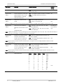
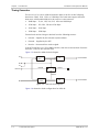
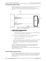
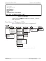
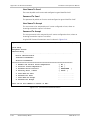
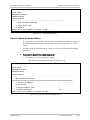
Figure 4-3. Local Digital Loopback
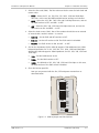
To activate the local digital loopback:
•
Press the DIG pushbutton on the local ASM-40 front panel.
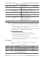
The following LEDs are ON:
Local unit: TEST, RTS, and TD
Remote unit: DCD, RTS, TD and RD.
Note
You can activate the local digital loopback by running remote digital loopback at
the remote unit. If the V54E section of the SW3 DIP switch is set to ON, the local
ASM-40 closes the DIG loopback when it detects the RLB activation at the remote
end.
4.2
Internal BERT
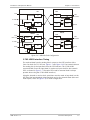
ASM-40 has a built-in BERT circuit consisting of a pattern generator and a pattern
tester. This circuit works in conjunction with the V.54 diagnostic loops and the
remote BERT to verify normal system operation and identify faulty equipment in
the event of the system failure.
The pattern transmitted by the BER system can be looped back for comparison
(modem self-test) or can be received by another ASM-40 (Two-BER test).
When used opposite another ASM-40, the complete link can be tested either
when the PATT button is pressed, or with external BERT transmitting the same
511-bit pattern.
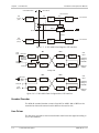
Modem Self-Test
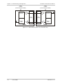
The test verifies that the modem is operating correctly (see Figure 4-4).
To activate the modem self-test:
1. Press the ANA pushbutton on the front panel. The TEST and DCD LEDs light
up.
4-4
Internal BERT
ASM-40 Ver. 1.0