1
OVERVIEW
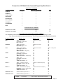
Effective with M1 Control firmware 5.1.24 and later it is now possible to control specific brands/models (see page 2)
of distributed audio systems using the M1. The primary communications medium is TCP-IP (LAN “Network”),
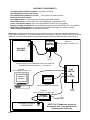
whick requires the use of a Ness-M1XEP “Ethernet Port Interface”, and a Elk-IP232 “IP to Serial Adapter”. The IP232
connects to the serial port of the audio controller. In addition, some audio controllers require an additional piece of
hardware to accomodate a RS232 communications connection. The M1 Control, M1XEP, and IP232 will need to
have the most recent firmware (see page 2), and may require flash updating. This application document is intended
to assist with installation and operation of the M1 equipment. It is beyond the scope of this document to assist
with setup of the audio equipment. The audio equipment should be completely setup and functional, and the
Installer should be familiar with it’s setup and operation PRIOR to connection of the M1 equipment. For questions
about the audio equipment please consult the audio manufacturer or the manual supplied with that equipment.
HOW M1 AUDIO COMMANDS FUNCTION
M1 Audio commands can originate from a M1 Automation Rule (“Then” command) or from a PC or M1 Touchscreen
running RM Remote Management software. The M1XEP receives commands and traffics them to/from the audio
equipment. The M1XEP contains detailed information about the audio brand/model, the zone and source names,
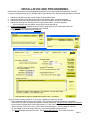
and the IP address for connecting with the IP232. Setup for all this information is done from ElkRP2 Programming
Software, under a new tab on the M1XEP Setup screen. Two new command types “CD” and “CA”, were added to
http://www.ness.com.au/downloadcenter.asp
for use by the
the M1 ASCII serial protocol
M1XEP. The M1XEP converts the ASCII commands into the appropriate native protocol of the audio controller.
PLEASE NOTE: There are no menus or buttons on an M1 Keypad that can support direct audio commands.
However, it is possible to use other actions from a keypad (function keys, arm, disarm, etc.) to fire a task or trip
an automation rule which can in turn send an audio command.
M1 AUTOMATION RULES
The three portions of an M1 Automation Rule are: Whenever, And, Then. The “Whenever” defines an action or event
used as a trigger. The “Then” defines the action e.g. audio command to be executed or transmitted. The “And”
defines a conditional e.g filter that might either allow or disallow a command based on a specific condition being
true or not true. In other words, if a rule contains “And” statements they ALL must be true in order for the
succeeding “Then” command(s) to execute. Below is a rule example which turns the audio Zone 1 On if the alarm
system is disarmed withing a certain time period.
WHENEVER alarm system becomes disarmed
AND the time of day is earlier than 11:00pm
AND the time is later than than 8:00am
THEN turn audio zone 1 ON
Audio commands are only available from “Then” elements. The M1 does not monitor or concern itself with the state
or present condition of an attached audio controller, therefore it is not possible for a rule to be triggered or filtered on
the audio state or condition. Commands are one way, going from the M1 to the audio controller. Some commands
are acknowledged by the audio controller, and may result in a response or display by the RMS Remote software,
or by a higher level 3rd party software. However, the M1 ignores the acknowledgements.
Source equipment attached to the audio controller may or may not be controllable from the M1 Automation Rules.
The level of integration with source equipment varies by the particular brand/model of the audio equipment. Audio
systems that maintain extensive knowledge of their attached sources do not necessarily share this through their
“third party” RS232 serial ports, even though it may be viewable on their attached system keypads, etc.
As previously mentioned, all audio commands are communicated through the Ness-M1XEP Ethernet Interface across
the LAN to an Elk-IP232 module. Setup involves programming the M1XEP will the IP address and Port number for
the IP232 module, followed by a setting of which audio partner is to be connected. After this the Source and Zone
names need to entered so that data will all become populated into the rules statements.
Page 3