1
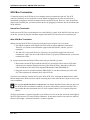
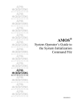
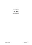
PDI-00642-00
December 1997
AM-642 Fintec STOP Converter
Installation Instructions
INTRODUCTION
This document describes the installation of an AM-642 FPS STOP (SCSI-to-Pertec) Converter into an
existing Alpha Micro Computer System.
If you do not feel comfortable performing the hardware and software procedures discussed below, please
contact your Alpha Micro dealer or the Alpha Micro Technical Assistance Center for help.
PRODUCT DESCRIPTION
The FPS STOP Converter allows you to connect a ½” magnetic tape drive to the SCSI bus and copy files
to and from it using the standard MTUxxx commands. It is available in two forms:
• PDB-00642-00: an external subsystem which plugs into your computer’s external SCSI port. For
additional information about the externally connected AM-642 subsystem, please see the
Installation Manual included with the STOP Converter.
• PDB-00642-01: an assembly which mounts in the card cage inside an AM-990 chassis, attaching
to the SCSI bus via the internal SCSI cable and to the ½” tape drive via cables running out the
computer’s back panel.
SCSI Bus Types
Over the years, Alpha Micro computers have offered three different “SCSI” busses. We refer to them as
follows:
1. The bus in AM-2000/3000 and other older computers, which supports up to four SCSI devices, is
the “SASI bus.”
2. The SCSI bus in Eagles, Roadrunners, the AM-4000, and newer computers, which requires a
SCSI dispatcher and supports up to seven devices, is the “SCSI-2 bus.”
3. The enhanced Wide SCSI-2 bus introduced on the AM-6000 and Roadrunner 060 is the “Wide
SCSI-2 bus.” This bus supports up to 15 devices. Note that the cables and 68-pin connectors used
with the Wide SCSI-2 bus are physically narrower than previous SCSI cables
The AM-642 is supported only on the SCSI-2 and Wide SCSI-2 busses. It does not work on the SASI
bus.
Rev. A01
Page 2
Installation Instructions: AM-642 STOP Converter
MOUNTING THE AM-642 INTERNALLY
The internally-mounted AM-642 (PDB-00642-01) is available only with AM-6000 or Roadrunner 060
computers in an AM-990 or AM-990 jumbo chassis. For all other configurations you must use the
external subsystem, PDB-00642-00, described later in this document.
Here is an overview of the installation procedure:
1. Open your computer’s chassis and card cage, and remove the back I/O panel.
2. If necessary, remove the internal SCSI cable and replace it with the new one provided.
3. Slide the AM-642 assembly into the card cage and attach it to the new SCSI cable.
4. Route the cables from the AM-642 out the I/O panel to the tape drive.
The following sections describe the procedure in detail.
Electronic Equipment Handling Precautions
While your computer's hardware is exposed and the AC power cord is unplugged, the
components are vulnerable to damage caused by static discharge. Your body and clothing are
capable of storing an electrical charge that can damage or destroy unprotected electronic
components. Before you handle any computer hardware, make certain your work area is properly
protected against static discharge. There are a number of commercially available static protection
devices, like the wrist strap shown below, designed specifically to protect your equipment from
harmful static discharge.
Opening the Computer Chassis
1. Turn off power to the computer and unplug it.
Rev. A01
Installation Instructions: AM-642 STOP Converter
Page 3
2. Remove the top and side from the AM-990 chassis, following the instructions in the AM-990
Service Manual.
3. Remove the cover from the card cage.
4. Remove the I/O rear panel so you can insert boards into the card cage.
5. Remove the card cage top bracket (DWF-20304-00). This piece is not needed with the AM-642;
you will not re-install it.
6. Make sure the AM-319-20 is in the bottom slot of the card cage, and the AM-176 is in the third
slot. Take the nylon screw included in the AM-642 kit and screw it into the middle standoff of
the card cage that lines up with the third slot. This prevents the AM-176 board connector from
shorting against the card cage standoffs.
Install the New SCSI Cable
The AM-642 installation kit includes a new SCSI cable. The first connector on this cable is closer to the
end of the cable than on other Alpha Micro SCSI cables, allowing you to easily attach it to the AM-642
connector. If your existing SCSI cable will properly route and connect to the AM-642 after it’s installed,
you can skip this part of the procedure.
1. Carefully unplug all SCSI devices from the SCSI cable, unscrew the external SCSI connector
from the top-mounting bracket, and remove the SCSI cable.
2. Install the new SCSI cable, attaching it to the external SCSI connector and to each existing SCSI
device. Leave the first connector, approximately 6” from the CPU board SCSI connector, empty.
This is where you will attach the AM-642. Do not plug the SCSI cable into the AM-176 SCSI
connector.
3. Remember to plug the external terminator back into the new external connector.
Installing the AM-642
1. Before inserting the AM-642 into the card cage, be sure to set its SCSI ID. To do so, use the dip
switches at SW1, positions 6, 7, and 8. In the following diagram, “On” is toward the center of the
AM-642 board. Do not change any switches other than 6, 7, and 8.
On
On
1 2 3 4 5 6 7 8
SCSI ID 0
On
1 2 3 4 5 6 7 8
1 2 3 4 5 6 7 8
SCSI ID 1
SCSI ID 2
On
On
On
1 2 3 4 5 6 7 8
SCSI ID 4
On
1 2 3 4 5 6 7 8
SCSI ID 5
1 2 3 4 5 6 7 8
SCSI ID 3
1 2 3 4 5 6 7 8
SCSI ID 6
SCSI ID Switches
2. Slide the AM-642 assembly (the AM-642 board itself and its mounting board) into the top slot of
the card cage. The AM-642 faces toward the top of the card cage, with the SCSI connector
toward the I/O rear panel.
Rev. A01
Page 4
Installation Instructions: AM-642 STOP Converter
3. Attach the first connector of the new SCSI cable (not the CPU connector on the end) to the SCSI
connector on the AM-642. If you are using the Wide SCSI-2 bus, you need to use the provided
68- to 50-pin adapter (PRA-00259-00) between the SCSI cable and the AM-642.
4. Plug a 4-pin power connector from the power supply into the power connector on the AM-642. If
you don’t have any connectors available, use the “Y” power cable included in the AM-642 kit
(DWB-10265-01) to split power from one of the existing peripherals.
5. Attach the DWF-20782-00 retainer bracket to lock the AM-642 assembly in the card cage.
Installing the External Cables
1. Remove the I/O cover plate or paddle card from the top slot in the I/O rear panel.
2. Install the shielded cable-mounting bracket (DWF-20171-00) in the top slot of the I/O rear panel.
Position the bracket so the studs face away from any I/O paddle cards below it.
3. There are two external, 50-pin shielded cables included with the AM-642. One end of each cable
has a PC edge connector. Take the other end of one cable and slide it through the left slot of the
cable mounting bracket. Pin 1 of the cable, marked by a red stripe, should be toward the left.
Secure the cable grounding strap to the pair of studs on the bracket.
4. Take the other cable and slide it through the right slot of the bracket, with pin 1 to the left.
Again, the end with the PC edge connector stays outside the chassis. Secure one end of the cable
grounding strap to one stud on the bracket; attach the other to the bracket using a standard screw.
5. Reattach the I/O panel to the AM-990 chassis.
6. Route the two cables into the card cage and over the AM-642. Plug the left cable into J2 on the
AM-642; plug the right cable into J1. Make sure the red stripe on each cable is properly matched
to pin 1 on its connector.
7. Connect the other ends of the cables to the mag tape drive. Attach the left cable to P2 on the
drive and the right cable to P1. Label the cables so you can reconnect them properly if needed in
the future.
Finishing Up
You have now finished installing the AM-642. Reinstall the card cage cover, side panel, and top cover as
described in the AM-990 Service Manual.
ATTACHING THE AM-642 EXTERNALLY
To ensure proper operation of an external AM-642 subsystem (PDB-00642-00) on an AMOS computer,
you must be very careful about exactly how it is connected to the SCSI bus. Proper bus termination, as
discussed below, is critical to reliable AM-642 operation.
The AM-642 is a narrow SCSI device. As with any narrow device, if you want to attach it to the
Wide SCSI-2 bus, you need to use a 68 to 50-pin adapter, available from Alpha Micro. Also,
because it is a narrow device, you cannot set its SCSI ID above 6, even though the Wide SCSI-2
bus supports IDs up to 15.
Rev. A01
Installation Instructions: AM-642 STOP Converter
Page 5
SCSI Bus Termination
To function properly, the SCSI bus on your computer must be terminated at each end. The SCSI
controller terminates one end of the bus; in most AMOS configurations, the other end of the bus is
terminated by plugging an external terminator into the external SCSI port. However, since the AM-642
plugs into the external port, you must terminate the bus by plugging a terminator into the terminator port
on the AM-642.
Narrow Bus Termination
On the narrow SCSI 2 bus, terminating the bus at the AM-642 is simple. If the AM-642 is the last device
on the bus, you merely plug the terminator supplied with the STOP converter into its terminator port.
Wide SCSI Bus Termination
Making sure the Wide SCSI bus is properly terminated is more complex, for two reasons:
• All AMOS computers which support the Wide SCSI bus require active bus termination.
Therefore, you cannot use the terminator supplied with the AM-642, which is a passive
terminator.
• The AM-642 is a narrow SCSI device. Therefore, any terminator plugged into it does not
terminate the “high” nine lines of the Wide SCSI bus. To properly terminate the bus, you need to
terminate these lines.
So, to properly terminate the Wide SCSI bus when using an AM-642, you must:
1. Between the external SCSI port and the AM-642, use an external wide-to-narrow SCSI cable
which actively terminates the high nine lines of the Wide SCSI bus. Alpha Micro offers this
cable in both three-foot and six-foot lengths (PDB-00440-80 and PDB-00440-81).
2. Plug a narrow active external terminator (PRA-00222-21) into the terminator port of the AM642. This terminates the remaining lines of the SCSI bus.
If you have more than one external device on the Wide SCSI-2 bus, terminate the high nine lines where
the bus changes from Wide to narrow, and the remaining lines at the end of the bus. Again, be sure to use
active terminators.
Be sure that only the last device on the bus has a terminator installed. If more than one device on
the SCSI bus has its termination enabled, your system will probably perform erratically! This is
true whether the other terminated device is in the computer chassis or in a separate subsystem
chassis.
SCSI bus performance, in general, degrades as you add more devices to the bus, and as the total length of
the SCSI cable increases. For most reliable performance, do not attach extra devices to the bus, and keep
the total cable length—internal and external—as short as possible.
Rev. A01
Page 6
Installation Instructions: AM-642 STOP Converter
Termination Power
All AMOS computers using the SCSI-2 or Wide SCSI-2 bus should be configured to supply termination
power via the host controller. When SCSI bus termination power is supplied by the host controller, no
SCSI peripheral, including the AM-642, should supply termination power to the bus.
SCSI subsystems attached to the main system should not have any additional devices supplying
termination power to the SCSI bus. Termination power should be supplied by the SCSI controller only!
The SCSI host controller on AM-190 and AM-540 boards is permanently configured to supply
termination power to the SCSI bus. On Roadrunner boards, the termination power feature can be
enabled or disabled by setting a jumper. As of 07/26/94, Alpha Micro began configuring all
Roadrunner boards with termination power enabled. See the Roadrunner installation instructions
for information on how to configure the termination power jumper.
Electrical Power
For reliable operation, the AM-642 should be plugged into the same power source as the computer it is
attached to. Do not plug it into a separate power circuit.
SOFTWARE INFORMATION
There are several points to remember when using the AM-642 STOP Converter:
• The following versions of software (or later) are required to support the AM-642:
For AMOS 1.X Systems
File
Version or Hash
MTUSAV.LIT
3.2(135)
MTURES.LIT
3.2(139)
645DVR.DVR
132-302-300-250
TAPSER.LIT
3.0(123)
TAPLOG.LIT
1.0(100)
SCZRR.SYS
1.0(117)
SCZ190.SYS
1.0(117
For AMOS 2.X Systems
File
Version or Hash
MTUSAV.LIT
3.1(121)
MTURES.LIT
3.3(139)
645DVR.DVR
132-302-300-250
TAPSER.LIT
3.0(123)
TAPLOG.LIT
1.0(100)
SCZRR.SYS
1.0(117)
SCZ190.SYS
1.0(117
SCZR60.SYS
1.0(107)
• You can have multiple SCSI tape drives attached to your computer system.
• The AM-642 should be referred to as device MTX0:.
• AMOS does not support warm booting from a tape drive attached to the AM-642.
Copying the Device Driver Program
You need to make a copy of the driver you require under a three-character name so AMOS can associate
it with the device name you are going to put in your system initialization file. To do so, type:
LOG DVR: RETURN
COPY MTX.DVR=645DVR.DVR
RETURN
Rev. A01
Installation Instructions: AM-642 STOP Converter
Page 7
Modifying the System Initialization Command File
To define the AM-642 to your computer, use the COPY command to make a copy of your system
initialization command file, calling it TEST.INI. Then edit that copy using the AlphaVUE text editor,
making the modifications discussed in the following sections.
Never modify the system initialization command file directly. Always make a copy and name it,
for example, TEST.INI. Make the modifications described below in that test file. When you have
finished, use MONTST at AMOS command level to test it. If it fails, you can push the reset
button to return to your standard initialization file. If you modify your AMOSL.INI or
AMOS32.INI file directly and make a mistake, the system may not boot at all. If the MONTST is
successful, you can then rename the test command file to AMOSL.INI or AMOS32.INI.
Type the following commands to create a test initialization file. For example, if your computer runs
under AMOS/32, enter:
LOG SYS: RETURN
COPY TEST.INI=AMOS32.INI
RETURN
Make sure your system backup media contains the AM-642 software files in case you need to restore
your system.
Modifying the Device Table
The first thing you need to do in your TEST.INI file is add a new DEVTBL statement. When used in the
system initialization command file, DEVTBL tells AMOS which devices to look for on the computer. As
AMOS processes the DEVTBL command line, it builds a device table in memory. The file system
consults the device table for device assignments. Every time you add a new device to the system, like
your SCSI streamer drive, you must add it to the system device table.
Locate the DEVTBL statements in your TEST.INI file. Add one that looks like this:
DEVTBL /MTX0
The slash preceding the device name lets AMOS know the device is non-sharable.
Since the device driver program needs to be in system memory, add the following SYSTEM command
prior to the final SYSTEM command:
SYSTEM MTX.DVR[1,6]
Since the MTUxxx programs spawn a separate job to communicate with the tape drive, you may need to
increase the number of jobs allocated by the system at boot time. To increase the number of jobs, find the
line which reads:
JOBS nnn
This line is normally one of the first commands in the .INI file. Increase the number of jobs by one.
Rev. A01
Page 8
Installation Instructions: AM-642 STOP Converter
Testing the Initialization File
When you have finished editing the TEST.INI file, and the AM-642 is properly attached to the computer,
press the ESC key and type F at AlphaVUE command level to exit. Then log into OPR: (make sure
everyone is off your system) and use MONTST to test the TEST.INI file.
When your computer executes the DEVTBL statement DEVTBL /MTX0 located in your system
initialization command, it will display if an AM-642 was detected and its address. For example:
AM-642 mag tape found at SCSI ID: 3
If the computer boots successfully, enter DEVTBL to see a display of the devices on your system; the
AM-642 should be listed as MTX0.
If the computer doesn't boot successfully, or if the AM-642 does not appear on the DEVTBL display,
press the RESET button to reboot the computer under its original initialization file. Review the changes
you made to the TEST.INI, and verify the AM-642 is attached correctly.
Initial System Testing
You may want to run the system self test, once the computer is up and running, to be sure your computer
system is operating correctly. Refer to your computer Owner's Manual for complete step-by-step
instructions and interpretation of the self test.
Self test does not test the AM-642.
Use the MTUSAV command to copy a few files onto a blank mag tape, and then use the MTURES
command to restore them into a different disk account, or onto another logical disk. The MTUDIR
command lists the files stored on the tape.
Tape Spanning
The AM-642 cannot span tapes! Later versions of the tape backup software do not allow tape
spanning at all with this drive. However, earlier software versions will attempt to span tapes with
the AM-642. However, this will not work.
ADDITIONAL DOCUMENTATION
A number of other Alpha Micro documents amplify the concepts discussed in this document. Your
primary reference source should be your computer Owner's Manual. Subjects thoroughly covered in the
Owner's Manual include:
1. Physical and electrical specifications.
2. Cooling and system placement.
3. Power requirements and power conversion.
Rev. A01
Installation Instructions: AM-642 STOP Converter
Page 9
Another useful document is your System Commands Reference Manual. In it you will find reference
sheets for the AMOS system software programs and commands mentioned in this document. Also, see
your System Operator's Guide for a wide variety of system information and the System Operator’s Guide
to the System Initialization Command File for information about system initialization configuration.
Rev. A01