1
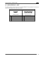
25-PIN CABLE ELECTRICAL CONNECTIONS
5
5.8 INPUTS
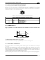
There are two optocoupled polarity insensitive inputs available on the 25-pin connector of the
reader: Input 1 (External Trigger) and Input 2, a generic input:
The External Trigger can be used in One Shot Mode or in Phase Mode. Its main functions
are:
acquisition trigger in One Shot Mode
reading phase-ON/reading phase-OFF command in Phase Mode
The main functions of the general purpose Input 2 are:
second external trigger in Phase Mode
match code storage command when the Match Code option is enabled
The electrical features of both inputs are:
Maximum voltage:
30 Vdc
Maximum current:
12 mA
The active state of these inputs are selected in software. Refer to the VisiSet™ Help On
Line.
An anti-disturbance filter is implemented in software on both inputs so that the minimum
pulse duration is
0.5 milliseconds. This value can be increased through the software
parameter Debounce Filter, see the Digital I/O folder in the VisiSet™ Help On Line for further
details.
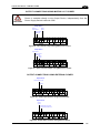
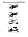
These inputs are optocoupled and can be driven by both NPN and PNP type commands.
Polarity insensitive inputs assure full functionality even if pins A and B are
exchanged.
NOTE
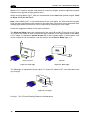
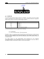
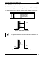
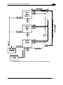
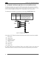
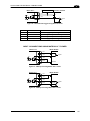
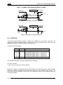
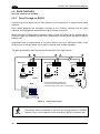
The connections are indicated in the following diagrams:
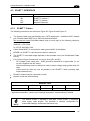
Pin
9
18
19
7
Name
Vdc
I1A
I1B
GND
Function
Power Supply input voltage +
External Trigger A (polarity insensitive)
External Trigger B (polarity insensitive)
Power Supply input voltage -
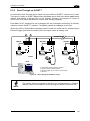
The yellow Trigger LED (Figure 15, 5) is on when the active state of the External Trigger
corresponds to ON.
73