1
MATRIX 210™ REFERENCE MANUAL
5
5.10 USER INTERFACE
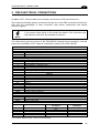
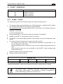
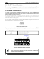
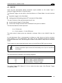
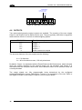
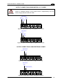
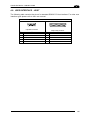
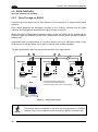
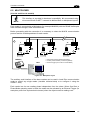
The following table contains the pinout for standard RS232 PC Host interface. For other user
interface types please refer to their own manual.
RS232 PC-side connections
1
5
1
6
14
9
9-pin male connector
Pin
2
3
5
7
8
13
25
25-pin male connector
Name
RX
TX
GND
RTS
CTS
Pin
3
2
7
4
5
Name
RX
TX
GND
RTS
CTS
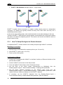
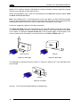
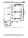
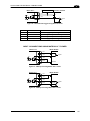
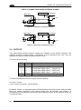
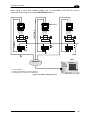
How To Build A Simple Interface Test Cable:
The following wiring diagram shows a simple test cable including power, external (pushbutton) trigger and PC RS232 COM port connections.
25-pin D-sub male
9-pin D-sub female
21
TX
2
RX
20
RX
3
TX
GND
5
GND
7
13 Vdc
Matrix 210™
25 GND
13 Vdc
18 I1A
19 I1B
Power Supply
Vdc (10 – 30 Vdc)
Power GND
Trigger
Test Cable for Matrix 210™
Figure 87- Test Cable for Matrix 210™
78
PC