1
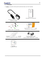
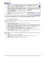
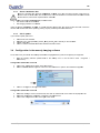
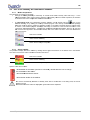
IN NSTALLLATIO ON AND U USER MANUA M AL Versio on 03 • Juuly 18, 2012 EN Index 1 INTRO ODUCTION .................... . ................................................................................................................... 3 1.1 1.2 1.3 1.4 1.5 1.6 COM MPLIANCE WIT TH STANDARDS ............................................................................ .................................. 3 POW WER SUPPLY .................... . ............................................................................... .................................. 3 INSTTALLATION PR RECAUTIONS................................................................................. .................................. 4 LIAB BILITY AND OP PERATORS.................................................................................... .................................. 4 PAC CKAGING AND ENVIRONMEN NT ............................................................................ .................................. 5 MAR RKING AND LA ABELLING SYMBOLS ....................................................................... .................................. 5 2 CONT TENTS ................................................................................................................................................ 6 3 INSTA ALLATION ......................................................................................................................................... 7 3.1 3.2 3.3 3.4 3.5 PRE ECAUTIONS ....................................................................................................... .................................. 7 EQU UIPMENT INST TALLATION .................................................................................... .................................. 8 SOFFTWARE INSTA ALLATION ..................................................................................... .................................. 9 CON NFIGURATION IN THE OWAN NDY IMAGING S SOFTWARE .......................................... ................................ 11 SHA ARING THE SENSOR AND BO OX BETWEEN D DIFFERENT WO ORKSTATIONS S .................. ................................ 12 4 USE........................................................................................................................................................... 13 4.1 4.2 4.3 4.4 4.5 PRE ECAUTIONS ....................................................................................................... ................................ 13 SEN NSOR PRINCIP PLES ............................................................................................ ................................ 13 USE E OF THE OWA ANDY XIO STA ANDALONE SO OFTWARE ............................................ ................................ 14 ACQ QUISITION OF AN A IMAGE .................................................................................... ................................ 16 EXP POSURE TIMES S ................................................................................................. ................................ 17 5 HYGIE ENE AND MAINTENANC M CE ............................................................................................................ 18 5.1 5.2 5.3 HYG GIENE AND DIS SINFECTION ................................................................................. ................................ 18 REC COMMENDED CLEANING C AND DECONTAM INATION PROC CEDURE ........................... ................................ 19 MAINTENANCE ...................................................................................................... ................................ 19 6 TROU UBLESHOOT TING ............................................................................................................................ 20 6.1 6.2 GEN NERAL .............................................................................................................. ................................ 20 IMAG GE QUALITY ..................................................................................................... ................................ 21 7 SPEC CIFICATIONS S................................................................................................................................... 22 7.1 7.2 GEN NERAL SPECIF FICATIONS .................................................................................... ................................ 22 REG GULATORY DECLARATIONS E ............................................................................... ................................ 23 8 ACCE ESSORIES ........................................................................................................................................ 26 The manufaccturer, OWAND DY, reserves the e right to make modifications to t its products or o to their speciifications in ord der to improve the performa ance, quality, orr ease of produc ction. Specificatitions of products s or accessories s may be modifified without priorr notice. his manual may be reproduced without the prio or consent of the e manufacturer, Owandy. No part of th Language off original docum ment: French. Year CE marking assigne ed: 2012 nd OPTEO 2 g generation – Usser manual OWANDY Le e Coruscant - 2, rue des Vie eilles Vignes 777183 Croissy y-Beaubourg FRANCE Telepphone : +33 1.64.11.18.18 Fax : +33 1.64.11.18.10 Page 2/26 EN 1 Intrroductio on You have jjust received your Opteo new n generatio on digital intra a-oral radiolog gy kit, with dirrect USB conn nection. We thank you ffor the confide ence you have e in us and hop pe that this pro oduct will give e you entire saatisfaction. mend you to read this man nual thorough hly before insttallation; follow wing the guideelines for insttallation and We recomm usage desccribed in it willl exclude risk ks to the patie ent and the ca are team. Plea ase keep it cloose to your eq quipment so you can reffer to it at a latter date. Your senso or uses an X-ray sensitive electronic dettector (the flatt part at the bottom b of the ssensor) that replaces r the conventional film used fo or the acquisittion of radiolo ogical intra-ora al images. The e X-rays are aautomatically detected by the sensor which triggerss image acquisition. The acq quired image is displayed almost a instantaaneously on th he screen of the computter to which th he sensor is connected. c Th hese digital im mages can the en be manipulaated, analyse ed, saved as files or printed. The develo opment processs of conventional films is thus complete ely eliminated as well as thhe possible in nfluences on image quallity; such as the type and age a of the che emical produc ct, the temperrature of the bbaths or the development d time. on the kit you u have ordere ed you The sensor is available in two sizes;; depending o received a size 1, a size 2 sensor or both: Th he size 1 sen nsor allows yo ou to acquire the majority of intra-oral im mages (peri-apical and retro-coronarry) both vertica ally and horizo ontally. Th he size 2 se ensor furtherm more allows yyou to easily y acquire horizontal “bitewing” image es. The instrucctions and infformation in th his manual re efer to both sensor s sizes, unless specifically stated. The size s of the sensor is marked d on the senso or itself. 1.1 Co ompliance with standards The Opteo o kit is class IIA equipmen nt within the meaning of the t European n Directive 933/42/CEE con ncerning CE markings. T The Opteo kit complies with h the EN/IEC6 60601-1 medic cal standard. ain conditionss (see chap. 1.3 1 “Installatio on precautions s”) it is necessary that the other compon nents of the Under certa system tha at are possibly connected (computer an nd optional pe eripherals) arre also complliant to standard IEC950 (EN60950) and that the installation i com mplies with th e EN/IEC6060 01-1 standard. The intra-oral sensor is contained c with hin a hermetic and sealed ca ase (resistant to immersion)). There is no o physical or electrical e conne ection betwee en the Opteo kit k and the X-rray generator. 1.2 Pow wer supplly The power to the Opteo box is provide ed directly by tthe power sup pply of the USB cable conneecting it to the e computer. nd OPTEO 2 g generation – Usser manual Page 3/26 EN 1.3 Ins stallation precaution p ns A As the intra-oral sensor is situated s inside e the patient environment e (less than 1,5m m / 4.9ft from the patient), yyour compute er must neces ssarily complyy with standarrd EN/IEC60601-1, or yourr installation in ncluding the ccomputer must have been n rendered co ompliant with standard EN N/IEC60601-1--1. You can connect c the ssensor to you ur computer without w additio nal precaution ns once your complete insttallation is compliant with standard EN/IEC60601-1 1. puter is not siituated in the patient enviro onment and is not complia ant with standdard EN/IEC60 0601-1, it is If the comp necessary tto place the se ensor in non-c conductive pa ckaging. T The Opteo se ensor is an ele ectrical mediccal device requ uiring special precautions re regarding elec ctromagnetic ccompatibility. Please observ ve the recom mendations in n this manual during the coommissioning and use of tthe equipmentt. T The use of ca ables or acces ssories other tthan those sp pecified in this s manual can cause an increase in the e emissions or a reduction in the immunity of the Opteo sensor. 1.4 Lia ability and d operators s Installer: tthe installation n of the kit re equires comp puter skills relating to both h equipment aand software. Follow the recommend dations and gu uidelines of th he installation cchapter to install the equipm ment and softw ware. User: the kkit must be use ed by a dental practitioner. T The sensor sh hould never be opened by the user. Only the manufacturer is authoorised to open and make rrepairs to the e sensor. Re eturn the equ uipment to the distributor in case of m malfunction and/or if the d documentation n you possess s does not co ontain the necessary information for the ((authorised) maintenance m o of the malfuncctioning equipm ment. A Any modification of the Op pteo device is forbidden. All repairs of this same devicce can only be e performed b by OWANDY personnel. The manufa acturer will no ot be liable if: Intterventions or repairs hav ve been made e by persons s without the authorizationn of the manufacturer or disstributor and are a not part off accepted inte erventions. Th he equipment is used with an a installation that is not co ompliant with the t applicablee standards an nd decrees in particular when not compliant with the E EN/IEC60601--1-1 standard relating to thee security rules for electro ms. Make sure the installation n of the equip pment is compliant with the aapplicable reg gulations. medical system o than those mentioned d specifically in n this manual (use of the kkit in normal conditions c of Ussed in ways other usse and in compliance with its intended pu rpose). nd OPTEO 2 g generation – Usser manual Page 4/26 EN 1.5 Pac ckaging and a enviro onment Transport,, storage and environme ent: the kit iss supplied in protective packaging (prootection again nst physical impacts and antistatic pa ackaging). It must m be stored under the folllowing conditio ons: Ambient tem mperature: -10 0°C to +70°C / 14°F to 158°°F Relative humidity: <9 95% without co ondensation Atmospheric pressure: 500hPa to 1060 0hPa ernational saffety standard EN/IEC601-1 (section 2), thhe kit has bee en designed Operation:: in compliancce with the inte for normal u use under the e following con nditions: Ambient tem mperature: +10°C to +40°C / 50°F to 104 4°F Relative humidity: 30% to 75% 0hPa Atmospheric pressure: 700hPa to 1060 o distributor:: should a retturn to the diistributor be nnecessary, make sure to Equipmentt packaging for return to package the sensor and box kit in its original o packag ging after having cleaned it thoroughly. documentation. Please con pped with its d ntact your disttributor for a replacement r Documenttation loss: all kits are ship manual if th his documenta ation is lost. 1.6 Ma arking and d labelling symbols These symbols are used d on the product labels and inform you ab bout the compliance with staandards and the technical specificatio ons of the com mponent. Direct current. Type B equippment, EN/IEC C 60-601-1, annexes I annd II. The CE C marking certifies that this prroduct complie es with European directive 93/42 CEE. Important infformation: follow the instructions printed in this s manual. Senso or waterproo ofness stand dard, EN/CE EI 60529 regulation. Only the t part of th he sensor puttted in month, m comp plies with this standard. Storag ge condition: relative r humid ity limitations Storage conndition: temperature limitations. Storage conndition: Atmos spheric pressure lim mitations. Equipment subject to a selective co ollection in acccordance witth Directive 2002/96/EC 2 oon waste elec ctrical and electronic e equipment (W WEEE) and with w Decree 2 2005-829 of the t 20th July 2005 regardding the comp position of electrical an nd electronic equipment e and the eliminatiion of waste coming c from th his equipment.. nd OPTEO 2 g generation – Usser manual Page 5/26 EN 2 Contents Your Opteo o kit consists of o the following elements (il lustrations ma ay vary from items supplied)): 1 self-adhe esive sensor w wall support An Opteo se ensor - size 1 or size 2 (cable of 3m / 9.9foo ot) Meta al positioner kit ((available for size s 1 sensor as a default) A bag o of disposable single-use hy ygienic protecttive sleevves (compatiblle with size 1 and a 2 sensorss) An introductory pack of plasstic positionerrs or size 2 sensoor as default) (available fo An O.S.P. installation CD-ROM ers/diagnosticc tools) (drive C with the t installationn files of the se ensor A CD-ROM A manual A packkaging checklist nd OPTEO 2 g generation – Usser manual Page 6/26 EN stallation n 3 Ins 3.1 Pre ecautions T The kit must be b handled with care, minim mise the twisting, pulling and bending of tthe attachmen nt cable. Do n not step or roll on the cable e. Do not pulll on the cable e itself but on the connectioon plug to dis sconnect the U USB cable. T To avoid interrferences in the t image, do o not use the system close e to strong m magnetic fields s and avoid p proximity to electrostatic em mission source es. R Read paragraph “0 Installation precaution ns” to ensure the t installation n complies witth the standard ds. IInstall your im maging software before th he installation n of the kit, its drivers annd O.S.P. too ols and the ensor. installation files of the se 3.1.1 Recomme ended minim mal configu ration A Any computer configuratio on that does not comply with the minimal recommeended configuration can p prevent the sttarting or proper functionin ng of the sens sor kit. Verify y the specificaations of the computer(s) b before the insttallation. Operating ssystem Windows XP P SP2, Vista or o Seven (32 and a 64 bits) Computer Motherboarrd USB port Compliant C CE-IEC950 Intel 1.4GHzz chipset and processor USB 2.0 Hig gh-Speed Graphics ca ard Monitor 64MB High resoluttion 1024x768 8 (15inch) RAM memo ory Hard disk 256MB 10GB CD-ROM d drive Backup sysstem 24x movable disk, Zip or Jaz sys stem, CD-ROM M/DVD… External/rem Printer Keyboard a and mouse Laser, inkjett, thermal At acquisitio on workstation n Opteo kit w with appropriate e drivers Imaging soft ftware X-ray generrator with electtronic timer If your com mputer does not n possess USB 2.0 portts, these can be added as s PCI/PCI exppress cards (for ( desktop computers)) or PCMCIA cards (for lap ptops). If the U USB ports do not provide enough e currennt, please use e a powered hub (with itts own power supply). The PCMCIA card ds need to be powered by an a external poower supply or connected to a powere ed hub if they do not provide e enough currrent. Please co ontact your IT T specialist for further inform mation. 3.1.2 Setup guidelines The compu uter and the sccreen with wh hich the senso or and the box x are used sho ould preferablyy be situated close to the chair, within n the field of vision v of the practitioner, p to o allow for imm mediate use. Provide P visuall access for th he patient to be able to sshare the radio ological inform mation with him m/her. The screen n must be placced so as to avoid any refle ctions or direc ct overhead illuminations thaat could be de etrimental to the visualizzation of the ra adiological ima ages. It must b be set up (con ntrast and brig ghtness) to dissplay as many y grey levels as possible e in the image.. nd OPTEO 2 g generation – Usser manual Page 7/26 EN The X-ray g generator has a great influe ence on the qu uality of the ac cquired images s. The kit is coompatible with h any kind of generator, be it high-freq quency or conv ventional. The e generator mu ust be equippe ed with an eleectronic timer (allowing for very short exposure time es) and must emit a dose sufficient for the acquisitio on of a good iimage (with enough e grey ake sure that your generato or is not worn n as the dose e emitted will be insufficientt and could in nfluence the levels). Ma quality of the acquired image. The en nergy emitted d by a genera ator diminishes s over time; w when in doub bt have your o the generato or is stable, anny movement of the head generator cchecked by a qualified technician. Make ssure he had of will induce movement blu ur in the acquired image. 3.2 Equipment installation n 3.2.1 Connectio on o sensor is fitte ed directly to a cable equipp ped with a US SB connector linking it direcctly to the com mputer. If the The Opteo distance be etween the se ensor and the computer is g greater than th he 3m / 9.8ft of o USB cable, it is possible to add USB cables by u using a USB distributor (“hub”) connected d to an externa al mains powe er supply, betw ween each cab ble. Connection n without hub Connection with power ssupplied hub M Make sure the e USB port of the computerr is preferably a USB 2.0 po ort. Only use U USB 2.0 cable es and hubs w with a USB 2.0 2 port and make m sure tha at the hub ha as its own ex xternal power supply (do not n use selfp powered hubss, drawing the e power from tthe USB cable). Each USB B cable shouldd not be longe er than 3m / 9 9.8ft. The kit iss compatible with w USB 1.1 p ports but with reduced imag ge transmissioon speed. The USB cable can be co onnected / dis sconnected wiithout the need d to power down the compuuter. Check thatt the sensor iss correctly co onnected: if th he sensor toolbar turns gre een after remooving the sen nsor from its support, it is powered correctly. 3.2.2 Sensor su upport The sensorr can be place ed on its self--adhesive sup pport supplied d with the kit. The support iis compatible with sensorss of size 1 or size 2. This support can be fixed on any a type of flaat orktop or a pa art of the chaiir. The sensorr will then be inserted into the fork of thhe surface: wo support takking care not to o impede the cable. D Do not mount the wall support upside-dow wn or horizonttally, the sensor could fall oon tthe ground and be damaged d. nd OPTEO 2 g generation – Usser manual Page 8/26 EN 3.3 Software ins stallation Install the O Owandy QuickkVision (or third party) imag ging software and check its proper functiooning before installing the equipment and its driverss. Refer to the e software man nual for the installation instrructions. Y You need adm ministrator righ hts for the insstallation and use of the so oftware and eqquipment. Ple ease contact yyour IT specialist to create a suitable userr account. 3.3.1 Installatio on of the driivers T The Opteo drivvers are only compatible wiith the Window ws XP (service e pack 2 or higgher), Window ws Vista and W Windows Seve en operating systems s – 32 a and 64 bits. Automatic c installation: insert the O.S S.P. CD-ROM M in the CD-RO OM-drive. The e interface will launch autom matically and will guide yyou through the t different in nstallation ste eps. Refer to the Windows help if the C CD-Rom does s not launch automatically. 1. 2. 3. 4. 5. 6. 7. 8. Se elect the desirred language in the main sccreen. The tab bs at the top of the page linkk to different pages p of the Ow wandy website e and provide more informa ation regarding g Owandy. Se elect “USB” in the menu tha at appears. Co onnect the USB U cable to the connectiion box and the USB 2.0 port of the computer. Windows W will au utomatically de etect your box x. d” that appea Ca ancel the win ndow “Add ha ardware wizard ars then click on “Click heere” in the win ndow of the O.S.P. installer.. In the new wind dow, confirm the t location off the drivers th hat is displaye ed by clicking on “Install”. This T location must correspon nd to the direc ctory of the drrivers on the O.S.P. O CD-RO OM. The driveer files are the en copied to yo our hard disk. Cllick on “Contin nue” in the me essage window w “Equipment installation” th hat appears. A confirmation window is displayed afterr the files hav ve been copie ed, it confirm ms the drivers have been ng “Opteo V2 USB: Installed d”. Click on “O OK” to close thhis window. insstalled correcttly by displayin Th hen continue the t installation n of the O.S.P . with referenc ce to paragrap ph “3.3.2 Instaallation of the O.S.P.”. O stallation: it iss also possible e to install the e drivers manu ually by using the “New harddware detecte ed assistant” Manual ins of Windowss. Follow these e steps: 1. 2. 3. 4. 5. 6. Co onnect the co onnection box to the USB 2 2.0 port of the e computer. Windows W will aautomatically detect your eq quipment and will display the “Found New w Hardware Wizard” W window w. If the wizard re equests the au uthorization to o connect to the Windows Update site, sselect “No, no ot this time”, nding on your version of Wiindows. then click on “Next”. This window does not appear depen Th he wizard will inform you itt has detecte d your “Opteo o V2 USB” kitt. Select “Insttall from a listt or specific loccation” then click on “Next” after making ssure the O.S.P P. CD-ROM is s inserted in thhe CD-ROM drive. Se elect “Don’t se earch. I will choose the drive er to install” an nd click on “Ne ext”. Cllick on “Have Disk” under th he list that is d displayed. If the window co ontaining this llist does not appear, a click on n “Show All De evices” then click on the “Ha ave Disk” button. Th he next window w will allow yo ou to navigate to the directo ory that contain ns the requiredd files; click on “Browse”. nd OPTEO 2 g generation – Usser manual Page 9/26 EN avigate to the “\drivers s\WIN_2000_X XP\OWandy USB” Na dirrectory on the e O.S.P. CD-ROM; this dirrectory contains the file e “ow_usb.inf””. Click on “OK K” to select thiis directory. 8. Th he previous window w now diisplays the loccation of the files f to be e installed: “E:\drivers\WIN “ N_2000_XP\O OWandy USB B” (E : representing th he letter of yo our CD-ROM drive, this can c be ding on your computer con nfiguration). Click on diffferent depend “O OK” to start the e installation. 9. Th he “Opteo V2 2 USB” driverrs are displayyed in the lis st (see op pposite); click on “Next”. 10. Cllick on “Contin nue” in the warning window “Device installation” that appears. “ in the la ast window of tthe wizard. 11. Finally click on “Exit” 7. Optteo V2 USB eo V2 USB”” is installed d under “Un iversal Seria al Bus The “Opte controllers”” in the “Devicce manager”. To reach this window click on the Works station icon wiith the right mouse button and select “Manage” in th he drop-down menu. In the window that appears a select “Device mannager”. 3.3.2 Installatio on of the O.S S.P. c installation:: the installation of the O.S S.P. tools is automatically proposed aftter the installation of the Automatic drivers. Reffer to the proccedure below. 1. 2. 3. 4. 5. 6. 7. 8. Se elect the desirred language in i the window that appears and click on “Next”. In the welcome screen click on o “Next”. Se here the softw elect the targe et directory (th he directory wh ware will be installed) by cliccking on “Brow wse” and by na avigating to th he desired dire ectory. If you use the QuickVision imaging software sselect the dire ectory where yo ou installed Qu uickVision (pro oposed by deffault). After ha aving selected the target direectory click on n “Next”. Cllick on “Install”” to start the copying c the file es. Affter the files ha ave been copied, select “Op pteo V2 USB” in the list thatt appears and click on “OK”. A window will in nform you of th he successful installation, close it by click king on “Exit”. Th he last window w displays the e location of th he O.S.P. tools; close this window w by cli cking on the red cross of the window (top p right). Cllose the main O.S.P. installa ation window if it is still disp played on-scre een. Manual ins stallation: if you y have follow wed the manu ual installation of the drivers s, you must staart the manua al installation of the O.S.P P. tools: 1. 2. 3. 4. Inssert the O.S.P P. CD-ROM in the CD-ROM M drive. Na avigate to the “\setups\CMO OS_XRAYS_B BOX_W2000_ _WXP” directorry on the O.S..P. CD-ROM. La aunch “setup.e exe”. Re efer to the auttomatic installa ation of the O..S.P. mentione ed above. nd OPTEO 2 g generation – Usser manual Page 10/26 EN 3.3.3 Sensor in nstallation fiiles E Each kit is prrovided with a sensor insta allation CD-R ROM of its ow wn; the serial number of th he sensor is w written on the CD-ROM and d on the conne ection box. Yo ou can therefore not use thee same CD-RO OM to install sseveral sensors; each sensor requires itss own CD-ROM M. alling the senssor installatio on files, make e sure that: Before insta Th he drivers of th he kit are insta alled. Th he imaging software is not started. s OM, a window w appears an nd the files arre copied to tthe hard disk k. Close the Insert the ssensor installlation CD-RO window afte er the files havve been copie ed by pushing any key of the e keyboard wh hen asked for.. 3.3.4 O.S.P. up pdate If you need d to update you ur O.S.P.: 1. 2. 3. 4. Inssert the O.S.P P. CD-ROM. Na avigate to the “\setups\CMO OS_XRAYS_B BOX_W2000_ _WXP” directorry on the CD-R ROM. La aunch “setup.e exe”. Cllick on “Install or Reinstall” and a follow the e instructions on-screen. o 3.4 Co onfiguratio on in the Owandy O im maging software To be able to use your kiit with the Owa andy QuickVission imaging software s you must m configuree your equipm ment. 1. Sttart the imag ging software (double-clickk on the des sktop icon or use the linkk in Start / Programs / Qu uickVision). sion version 3 Configurattion QuickVis 2. 3. Cllick on the “Co onfiguration” button b in the m main screen. Se elect “OWAND DY DSX & Kry ystal-X” under the “Intra-Ora al sensor” optio on in the winddow that appea ars. 4. Cllick on “Config gure” at the rig ght of the men nu. Configurattion QuickVis sion version 4 2. 3. 4. Se elect the “Setttings” menu in the menu barr, then click on n “Preferences s”, then selectt the “Equipme ent” tab. Se elect the manu ufacturer “OW WANDY” underr the “Intra-ora al sensors”. Cllick on the con nfiguration buttton at the righ ht of the menu u. nd OPTEO 2 g generation – Usser manual Page 11/26 EN In the co onfiguration w window: ◄ Check the “USB” ttype. 2 ◄ Selec ct the “Opteo 2” kit. ◄ Set th he activation time of the box b (default 5min). 5 ◄ Set th he inlay and ssize of the date & time and d exposure pparameters in n the acquired d image. ◄ Selec ct the image ttreatment (*)). ◄ Config gure the Owa wandy software (**). (*) When th he “Film alike”” option is activ vated, the con ntrast depends s on the expos sure time. Adjjust the X-ray dose on the generator tto obtain a goo od image. (*) When yyou select the option “Auto contrast” the ccontrast is constant. Expos sure errors aree corrected au utomatically, which revea als noise in ba adly exposed images. In both casses, the expossure bar (blue//green/red) he elps to find the correct expos sure of the imaages. (**) This op ption appears only when the e sensor is ussed from certa ain Owandy so oftware prograams; it allows the change of the sharp pness setting or the high resolution for ea ach acquired image. i 5. Cllick on “OK” to o confirm yourr choice. 6. Th hen click on th he “Save” the settings. button (Qu uickVision 3) or o on the “Valid date” button (Q QuickVision 4) 4 to validate The use of the kit is identical to the use e of the Owan ndy XIO Stand dAlone softwarre described bbelow. 3.5 Sharing the sensor an nd box bettween diffferent worrkstations Sharing the sensor allo ows you to use u one or m more sensors s in turn in a practice w with multiple chairs. c It is ded to link th he different workstations w in n a network to allow for th he central stoorage and sha aring of the recommend images. A USB port must be plugged p into each e workstattion to allow for an easy connection oof the box. Windows W will automatically recognise the t equipmentt when it is co onnected and iti will be availa able immediattely for image acquisition. To enable the sharing of a kit betwee en different wo orkstations, it is necessary to first install the imaging software for the acquisition of the images, the driv vers, O.S.P. to sor installation n files on all tthe computers s with which ools and sens o will be used. your Opteo nd OPTEO 2 g generation – Usser manual Page 12/26 EN 4 Use e 4.1 Pre ecautions M Make sure the e sensitive su urface (the flatt surface) of the t sensor is directed towaards the X-ray y generator. T The active surrface of the se ensor is marke ed by a frame. The back of the sensor (roounded) does not react to X X-rays and do oes not produc ce an image o n-screen. T The kit must be manipulatted with care,, minimising the t twisting, pulling p and beending of the attachment ccable. Do nott step or roll on o the cable. Be careful no ot to pull on the t cable wheen removing the t hygienic p protective she eaths. he plug to discconnect the USB U cable. Do not pull on the cable itself, but on th E Even though the t sensor is resistant r to im mpacts, it is strrongly recomm mended to nott let it fall on the floor. If a p physical impact should exce eptionally hap ppen, contact your y distributo or and do not ttry to intervene e yourself. D Do not ask the e patient to bitte on the senssor or cable. Use of a mobile phone or an RF commun nications devic ce near the Op pteo sensor m may affect the sensor. 4.2 Sensor princ ciples 4.2.1 Sensor The sensorr’s sensitive area is delimite ed by a horizo ontal line; the area below th his line is not ssensitive to X--rays. When the sensor is placed in the t mouth it is s necessary to o check that this t area is turned towards the radiation source and a is irradiatted. that the whole sensitive area e surface Active 4.2.2 Sensorr’s rear shell:: inactive surrface Sensor ac ctivation The sensorr automaticallyy puts itself on n standby afte er a period which can be 4 Configuration in the configured in the configuration wind dow (see “3.4 maging softwarre” - the defau ult period is 5 minutes). The sensor’s Owandy im toolbar is th hen in its red state. s e your sensor physically, ju ust remove it from its supp port and/or To activate give it a slig ght jerk. The Opteo is equiipped with a g gravity sensor which will detect this movement an nd will so activate the emb bedded electro onics. The ensitivity to gravity g is prog grammed so as not to ac ctivate the sensor’s se Opteo intra a-oral sensor inopportunely by an involun ntary movemen nt. W When activating the senso or physically, take care to o hold the ssensor by both sides of its shells s and nott by the cable in order to a avoid any riskk of the cable e connections breaking or the t sensor ffalling and bre eaking. nd OPTEO 2 g generation – Usser manual Page 13/26 EN 4.3 Use of the Owandy O XIO StandA Alone softw ware 4.3.1 Modes off operation The sensorr kit can function in two way ys: Th hrough the Tw wain protoco ol (for scannerrs): to use thiis mode selec ct “Owandy Inntra Oral X-rays…” in the TW WAIN acquisittion option of your y imaging software. Sub bsequently sta art the TWAIN N acquisition; the t interface is identical to that of the indep pendent mode e described be elow. nt mode: the independent software pro ogram can be e started withh the ic con (on the In independen W Windows deskttop) or by sta arting an Owa andy software program. This memory reesident softwa are package oftware progra alllows the use of o the sensor outside any so am. If an imag ge is acquiredd without a pro ogram ready to receive it, th he resident pro ogram will dissplay the image on-screen for a few seeconds and sa ave it in the “C C:\Program Filles\OWANDY\\OSP - XRAY YS BOX STA ANDALONE\SttandAlone\Datta” directory on o the hard dissk. A sensor icon i appears in the Window ws taskbar, ne ext to the cloc ck. The colourr of the icon in ndicates the sta ate of the sensor: Red: sensor inactivve Yellow: sensor initiialising Green: sensor read dy for acquisittion 4.3.2 Sensor to oolbar It is possible to display the t sensor too olbar by clickin ng with the rig ght mouse button on the seensor icon in the taskbar. The colour of the sensor toolbar indica ates the state o of the sensor: Red: sensor inactivve Yellow: sensor initiialising Green: sensor read dy for acquisittion Options of tthe sensor too olbar: ◄ Orientatio on of the sen nsor (vertical or horizonta al), double-cliick the icon tto change the orientatio on of the sen nsor. ◄ Activate/d deactivate the sensor. ◄ Iconize th he toolbar in the taskbar. T The sensor automatically switches s to sttandby mode after a few minutes m of nott being used; the sensor ttoolbar turns red. r C Check that the e sensor toolbar is displayed d in green beffore each acqu uisition. nd OPTEO 2 g generation – Usser manual Page 14/26 EN 4.3.3 Configura ation menu A right-clickk on the senso or icon in the taskbar t or on tthe sensor too olbar displays the configurattion menu: X-ray sensor Displays th he sensor toolbar. Start when Windows sta arts Once checcked, the Stan ndAlone progra am will be launnched each time your comp puter is started d. Configura ation Displays tthe configuration menu (se ee “3.4 Conffiguration in the t Owandy im maging softwa are”). Display ne ew images forr Adjusts the e display time of the image. Allows you u to browse th hrough the ima ages waiting too be transferred. If no image e is acquired this t option is not n displayed. Closes the e resident softw ware program. Warning: thhe acquisition will w no longer b be available until u the resident program is restarted. Remaining g images Exit 4.3.4 Image tra ansfer interfa ace Options of tthe image tran nsfer interface e: Image dissplay Wh hen an image is selected, it is displayed on o a blue backkground. “Load” button Tra ansfers the se elected image to the softwarre program. “Cancel” b button Ca ancels the ima age selection and a starts the toolbar for a nnew acquisitio on (on nly when in a ssoftware progrram). “Preview” button Dis splays the sele ected image fu ull-screen. “Email” bu utton Op pens a blank e email and attac ches the image in a zip file. “Delete” b button De eletes the sele cted image. “Delete on n load” option De eletes the sele ected image frrom the list aftter it has beenn transferred to t a software s progrram. nd OPTEO 2 g generation – Usser manual Page 15/26 EN 4.4 Acquisition of an imag ge 4.4.1 Acquisitio on procedure The image acquisition go oes through se everal steps: 1. efore being able a to acquirre an image w with the sens sor, you need d to start the computer to which it is Be co onnected and start the imag ging software. Check that th he sensor toolb bar or the sennsor icon in the e task bar is grreen. 2. Prrogram the diffferent parame eters (exposurre time, etc.) on o the X-ray generator g (seee “4.5 Exposure times” for mo ore informatio on). 3. Co over the senso or with a hygie enic protective e sheath making sure to cov ver a sufficientt length of cab ble. 4. A set of position ners is provide ed with the kit to place the sensor s in the different d parts of the mouth;; their use is t ensure the sensor is posiitioned perpen ndicularly to th he X-ray beam m. recommended to Th he sensor can n also be posiitioned manua ally, maintaine ed by the patie ent as with coonventional film. This can be e necessary fo or children with h a small oral cavity. Positio on the sensor in the mouth, behind the tooth of which yo ou want to accquire an imag ge. If you do not use a po ositioner, a cotton roll can bbe helpful to position the se ensor parallel to t the tooth. Tu urn the sensitive surface of the senso or (the flat surface) towards the geneerator; if it is s facing the otther way, the sensor will not n be able to o acquire ima ages. 5. osition the generator so as s to cover the whole sensitive area of th he sensor. Thee paralleling technique t is Po strrongly recomm mended and the t use of possitioners allow ws you to corre ectly place thee generator th hanks to the aim ming ring. 6. enerator. The sensor toolba ar turns yellow w to indicate the treatmentt and transmis ssion of the Acctivate the ge accquired image e. Once the im mage treated, it appears in the imaging software and the sensor to oolbar turns grreen allowing a new acquisittion. 4.4.2 Imaging software s fun nctions An exposurre percentage e is displayed in i the acquired d image: 0 tto 80% - unde er-exposed image, the X-rayy dose is too low; increase the t X-ray dosee on the generator. 80 0 to 120% - co orrectly expose ed image image, the X--ray dose is too high; reduce 12 20 to 200% - over-exposed o e the X-ray doose on the gen nerator. When the image is displa ayed in the Owandy QuickV Vision imaging g software, a coloured bar aappears in the e top part of posure bar. Th his function is available only y to users of th he Owandy im maging softwarre. the image, this is the exp ed in this bar indicates the e exposure leve el of the image e: The white ccursor displaye If tthe cursor is in the green, th he image is co orrectly expos sed. If tthe cursor is in the red, the image is overr-exposed; red duce the exposure time on tthe generator. If tthe cursor is in the blue, the e image is und der-exposed; increase i the exposure e time on the genera ator. nd OPTEO 2 g generation – Usser manual Page 16/26 EN 4.5 Exposure tim mes Recommen nded exposure e times in seco onds for the O Owandy X-ray generators: Des scription Owan ndy Owandy-R RX Owandy Ellios AC Current / Voltage 7 7mA / 65KV 8mA / 700KV Lower incisor / canine 0 0.06 – 0.09 0.04 – 00.08 Lower premolar 0 0.06 – 0.10 0.06 – 00.10 Low wer molar 0 0.07 – 0.11 0.07 – 00.12 Upper incisor / canine 0 0.08 – 0.10 0.06 – 00.10 Upper premolar 0 0.08 – 0.11 0.08 – 00.12 Upp per molar 0 0.11 – 0.16 0.10 – 00.14 Refere ence condition ns: Adult patien nt, young man n or woman off average size e Distance fo ocal spot to se ensor 250mm / 9.8 8inch Total (inherrent) filtration equivalent to t 2mm / 0.08iinch Al The valuess indicated in the table abov ve can vary fro om one genera ator to another. It is the respponsibility of each e user to calibrate hiss/her doses before use. If an image e is over or un nder-exposed, it can be corrrected afterwa ards with the imaging softw ware (contrast,, brightness, etc.) to imp prove its visualisation. The table b below allows you y to note the e exposure tim mes specific to o your generato or: Des scription Adult d Child Lower incisor / canine Lower premolar Low wer molar Upper incisor / canine Upper premolar Upp per molar nd OPTEO 2 g generation – Usser manual Page 17/26 EN 5 Hyg giene and main ntenanc ce 5.1 Hygiene and d disinfecttion 5.1.1 USB Connector The connecctor does not require any particular ma aintenance, it should be cle eaned using a cloth and non-abrasive n detergents.. 5.1.2 Sensor To avoid crross-contamin nation between n patients durring use, it is necessary n to protect p the se nsor with hygienic singleuse protecttive sheaths (FDA cleared for f the USA, C CE marked fo or Europe). So ome hygienic protective she eaths suited for your reg gion are provid ded with each system. p the used sheath sho ould be throw wn away and the t sensor dissinfected applying a high Before eacch use on a patient, level disinfe ection procedure (see “5.2 Recommende ed cleaning and decontamiination proceddureErreur ! Aucun A nom n'a été don nné au signet.Erreur ! Auc cun nom n'a été donné au u signet.”). A new protectivve sheath is ap pplied to the sensor for each new pa atient. We rec commend the disposal of the hygienic protective p sheeaths with the biologically hazardous waste of yourr practice. TA HEALTHC Validated protections for North Am merica: BANT CARE or TID DI PRODUCTS S X-ray sens sor sheaths, CTS RS barrie ers. STERI-SHIIELD PRODUC D Do not pull on the cable whe en removing tthe used prote ective sheath. 5.1.3 Cables The cable can be cleaned with cautio on by using a disinfecting wipe. Hold the sensor withh one hand and, with the e of the sensor along the first f 20cm / 88inch of the ca able without other hand, apply a disinfecting wipe from the side pulling on tthe cable; sub bsequently cle ean the remain nder of the ca able in segments of 20-30ccm / 8-12inch with as little pinching off the cable as possible, the wipe w should sllide without ap pplying force. 5.1.4 Positione ers The positio oners provided d with the sy ystem should be covered by b the hygienic protective sheath togeth her with the sensor. D Do not pull on the cable whe en removing tthe sensor from m the position ner. They should be cleaned and disinfecte ed according tto the same procedure p as for the sensor (see “5.2 Rec commended nd decontamin nation procedu ureErreur ! Au ucun nom n'a a été donné au a signet.Erreeur ! Aucun nom n n'a été cleaning an donné au signet.”). The ey can be ste erilised, eitherr in an autocla ave (classic steam-sterilizerr, distilled water, 134°C / 273°F, 3ba ar, 4min) or using cold sterrilisation (see product instrructions). They y withstand a maximal tem mperature of 145°C / 293 3°F. e positioner ca an be thrown away a with the rregular waste. A defective nd OPTEO 2 g generation – Usser manual Page 18/26 EN 5.2 Recommend ded cleaning and de econtamin nation procedure Remove the hygienic pro otective sheath h (dispose of iit appropriately with the con ntaminated gorously wipe down the sensor to removve any visible e residues. If necessary waste). Vig rinse with ccopious amoun nts of water. Then T place the e sensor in the e disinfecting agent. a O Only immerse e the sensor and the head o of the positioner or sensor connection c ccable in the disinfectant d forr 15min, neve er immerse the connector on o the box sside of the possitioner or sen nsor connectio on cable in the e liquid. During the e immersion, brush the submerged pa arts with a soft s brush. Then T rinse thoroughly the sensor and a the positio oner or the se ensor connec ction cable witth copious amounts off fresh water. D Do not put the e sensor in a sterilizer s or an n autoclave, th he high temperature and e excessive high pressure will seriously d amage the ellectronics of the sensor a and connectorrs. D Do not clean the t sensor with inappropriatte instruments s (knife…). or, positioner or sensor con nnection cable e are not bein ng used imme ediately upon rinsing, as in the case of If the senso allowing the em to air-dry overnight o at th he end of a wo orking day, the ey should be rinsed with steerile water. When the ssensor, positio m from any damage, it is oner or senso or connection cable are not being used, to t protect them recommend ded to store th hem in their bo ox or to hang tthem in the se ensor wall sup pport. n using prote ective sheaths s, the sensorr should be disinfected re egularly. Imm merse the sen nsor in cold Even when sterilisation n fluid in acco ordance with the t instruction ns of the man nufacturer afte er having cleaaned it from all a residues. Never leave e the sensor immersed for longer than ne ecessary. 5.2.1 Recomme ended deco ontaminating g product fo or North-America The sensorr being sealed d watertight an nd to minimize e the potential for device-associated infecctions, the sen nsor and the part of the positioner or sensor s connection cable insserted in the mouth m shall be e disinfected w with an FDA-c cleared high level disinfe ection agent fo ollowing the in nstructions of tthe manufactu urer for use, sttorage, handli ng and warnin ng. The follow wing disinfecta ant agent ha as been valid dated with the sensor: CIDEX C OPA solution (0.5 55% Orthophthalaldeh hyde solution). The maximum soaking pe eriod is 24 hou urs. 5.2.2 Recomme ended deco ontaminating g products outside o North-America The following disinfectan nts are compa atible with the sensor and the part of the positioner orr sensor conne ection cable outh: that is inserrted in the mo 2% % Sodium Hyp pochlorite (ma aximum immerrsion time of 24 2 hours) Etthyl alcohol (m maximum immersion time off 24 hours) Qu uaternary amm monium 5.3 Ma aintenance e 5.3.1 Computer data-prote ection Your patien nt and image database must be backed--up regularly to be able to recuperate thhem if needed d (in case of hard disk o or computer problems). Ask k the advice o of your IT specialist with reg gard to the baackup system that is best suited to yo our computer configuration (external or rremovable hard disk, Zip or Jaz system, CD-ROM or DVD writer, etc.). Test a and store the copies in a sa afe place. nd OPTEO 2 g generation – Usser manual Page 19/26 EN 6 Tro oubleshooting occurs during operation, ch heck the differe ent items in th his troublesho ooting guide. Iff you cannot resolve r your If an error o problem ple ease contact your y distributo or. 6.1 Ge eneral Symptom Cause / Solution es not power up u or it does no ot The kit doe acquire ima ages. heck that the active surface e of the senssor is directed d Ch tow wards the X-ra ay generator and is positiooned correctly y in tthe field of the e X-ray beam. Ch heck that the kit k is correctly y configured inn the imaging g sofftware and tha at the drivers are a correctly innstalled. Ch heck the conn nection betwee en the sensorr and the PC,, and d ensure that the PC is pow wered externallly. Ch heck that the generator g is em mitting X-rayss (with anotherr sen nsor or with co onventional film). An n error has occ curred during acquisition, ddisconnect the e cab ble and wait a few seconds before reconnnecting it. Ch heck that the outer o sheath of the cable coonnection from m the e sensor does not show any y signs of teariing. No image a appears on the e screen. The sensorr is slightly wa arm. This is normal. The temperature of the sensoor can exceed d 12°C (5 54°F) when th he kit is activa ated for a prollonged period d (e.g. w when taking many m consecu utive images)) and has no o bearing g on the functio oning of the kit. nd OPTEO 2 g generation – Usser manual Re educe the stan ndby time in the configuratioon screen. Page 20/26 EN 6.2 Ima age qualitty Symptom Cause / Solution e The imagess are cut off, e.g.: The se ensor is badly positioned with regard to the X-ray y beam. The imagess are too light or contain noise, e.g.: eposition the sensor, s makin ng sure it is w well within the e Re fielld of the X-ray y beam. Usse the position ners provided with the senssor for optimal possitioning. The e image is un nder-exposed, the X-ray doose is too low;; inccrease the X-ray X dose on the ge nerator. The e perrcentage that is displayed in the imagee indicate the e exp posure level: o 0 to 80% % - under-exp posed image o 80 to 12 20% - correctly exposed im age o 120 to 200% 2 - over-e exposed imagee Ch heck the dose e emitted by th he X-ray geneerator, due to o age e the dose can c be insufficient. Have tthe generatorr che ecked by a tec chnician when n in doubt. Th e generator is s positioned to oo far from thhe patient with h gard to the sellected dose. reg Ch heck the para ameters of yo our monitor ((contrast and d brig ghtness) and avoid reflectio ons on the scre reen. The e image is ov ver-exposed, the t X-ray dosse is too high;; red duce the X-ray y dose on the generator. Thhe percentage e tha at is displaye ed in the ima age indicate tthe exposure e levvel: % - under-exp posed image o 0 to 80% o 80 to 12 20% - correctly exposed im age o 120 to 200% 2 - over-e exposed imagee Ch heck the para ameters of yo our monitor ((contrast and d brig ghtness) and avoid reflectio ons on the scre reen. Ch heck the qualitty and parame eters of the moonitor. Ch heck the conn nection of the cable of the screen at the e sid de of the graph hics card and the monitor. Ch heck the scree en configuratio on under Winndows (screen n con nfiguration pa anel, it must display colouurs in at leastt 24b bits. 211 1 Film alike m mode Au uto contrast mo ode The imagess are too darkk, e.g.: Grey levelss seem to be missing m in the image (flat areas of grey appear). The image is blurred. nd OPTEO 2 g generation – Usser manual Re-acq uire the image e: Th e patient has moved during the exposuree. s and has moved. Th e generator head was not stabilised Page 21/26 EN 7 Spe ecifications 7.1 Ge eneral specifications s Opteo Sen nsor - Size 1 External dim mensions size e 1 sensor CMOS mattrix size 1 senssor (cut corne ers) Sensitiive area in sizze Sensitiive area in pixxels Pixel d dimensions 38.6 x 24.7 x 5.2mm / 1.6 x 1.0 0 x 0.2inch 30 x 20mm (600mm2) / 1.2 x 0.8 8inch (1.0inch22) 1500 x 1000 0pixels 20 x 20µm Opteo Sen nsor - Size 2 External dim mensions size e 2 sensor CMOS mattrix size 2 senssor (cut corne ers) Sensitiive area in sizze Sensitiive area in pixxels Pixel d dimensions 43.2 x 30.8 x 5.2mm / 1.7 x 1.2 2 x 0.2inch 34 x 26mm (900mm2) / 1.3 x 1.0 0inch (1.3inch22) 1700 x 1300 0pixels 20 x 20µm Technical specification ns (size 1 and d 2 sensors) nsor cable) Length sen 3m / 9.9ft Grey levelss 14bits (1638 84 grey levelss) Connection n USB standa ard: USB 2.0 Hig gh-Speed (4800Mbit/s) and USB 3.0 Consumptio on kit 0.5VA unde er 5V (USB poort) Input voltag ge sensor Input curren nt sensor 0.15A Max Operating ttemperature +10°C to +4 40°C / 50°F too 104°F Lifespan CM MOS Min. 100,00 00 cycles Standards Conformity to standards nd OPTEO 2 g generation – Usser manual NF EN/IEC6 60601-1 NF EN/IEC6 60601-1-2 Page 22/26 EN 7.2 Regulatory Declaratio D ons Table 1 Man nufacturerr’s instruc ctions and declaratio on – electtromagnettic emissio ons The OPTEO model is de esigned for us se in the electtromagnetic en nvironment sp pecified below w. The OPTEO O customer or user musst ensure that it is used in such s an enviro onment. Emis ssions test Compliiance E Electromagne etic environm ment - instrucctions RF emissio ons Gro oup 1 T The OPTEO model m only use es RF energy for its internal functions. CISPR 11 C Consequently,, its RF emissions are very low and are not n capable o of causing inte erference in ne earby electronnic equipment. RF emissio ons Cla ass B T The OPTEO model m is suita able for use inn all premises s, including CISPR 11 d domestic prem mises and th hose directly connected to the low Harmonic e emissions Not ap pplicable vvoltage public electricity su upply networkk supplying bu uildings for IEC 61000--3-2 d domestic use. Voltage flucctuations/ Not ap pplicable flicker IEC 61000--3-3 Table 2 Man nufacturerr’s instruc ctions and d declaratiion – electtromagneetic immun nity The OPTEO model is de esigned for us se in the electtromagnetic en nvironment sp pecified below w. The OPTEO O customer or user musst ensure that it is used in such s an enviro onment. Immunity ttest I IEC 60601 Co mpliance Electrom magnetic envirronment - ins structions T Test level vel lev Electrostatiic ± 6 kV at conta act ± 6 kV at contactt Floors mu ust be of woood, concrete or o ceramic discharge tiles. ± 8 kV in the air a ± 8 kV in the air a covered w with synthetic materials, (ESD) If floors are IEC 61000--4-2 the relativ ve humidity muust be at leastt 30%. Rapid tran nsients in ± 2 kV for electricity Nott applicable The quality of the eleectricity supply network must be that of a typical comm bursts s supply lines mercial or hospital environment. e IEC 61000--4-4 ± 1 kV V for input/output lin nes Transient ± 1 kV between b Nott applicable The quality of the eleectricity supply network overvoltage must be that of a typical comm e p phases mercial or IEC 61000--4-5 hospital environment. e ± 2 kV between b p phase and earrth Nott applicable Voltage d dips, brief <5 < % UT The quality of the eleectricity supply network ( % dip in UT) mercial or power cuts and (>95 must be that of a typical comm variations in voltage for hospital environment. f 0.5 cycle e on electriccity supply userr requires continuous If the OPTEO O c input lines 4 % UT 40 operation during poweer cuts in the e electricity ( % dip in UT) (60 IEC 61000--4-11 etwork, it is re recommended to supply supply ne f 5 cycles for OPTEO from f an uninteerruptible ene ergy supply or a batte ery. 7 % UT 70 ( % dip in UT) (30 f 25 cycles for <5 % UT < ( (>95 % dip in UT) f 5s for 3 A/m Magnetic fiield at the 3A A/m Magnetic fields at tthe frequenc cy of the electricity network m frequency of the must have the t same network characterristic levels ass a representa ative place electricity (50/60 Hz) located in a typical ccommercial or o hospital IEC 61000--4-8 environment. NOTE: UT is the voltage of the alternattive network b before applicattion of the testt level. nd OPTEO 2 g generation – Usser manual Page 23/26 EN Table 3 Man nufacturerr’s instruc ctions and d declaratiion – electtromagneetic immun nity The OPTEO model is de esigned for us se in the electtromagnetic en nvironment sp pecified below w. The OPTEO O customer or user musst ensure that it is used in such s an enviro onment. Immunity ttest IE EC 60601 Compliiance Ele ectromagnetic c environmen nt - instructio ons T Test level Level 3V Conducted RF 3 Veff Porrtable and mo obile RF com mmunications equipment e frrom 150 kHz z to interference must not be us sed nearer too any part of o OPTEO, IEC 61000--4-6 8 MHz 80 inclluding the cables, thaan the reco ommended sep paration distance, calculateed on the ba asis of the equ uation applic cable to thhe frequency y of the tran nsmitter. Radiated RF 3 V/m e frrom 80 MHz z to 3 V/m interference commended separation s disttance Rec IEC 61000--4-3 2 GHz 2.5 1.16√P d=1 1.16√P from 80 MHz to 8000 MHz d=1 2.33√P from 800MHz to 2.55 GHz d=2 ere P is the transmitter’s m maximum outtput power whe rating in watts (W), accordinng to the tra ansmitter’s manufacturer and d is the reecommended separation es (m). disttance in metre The e field inten nsities of fifixed RF tra ansmitters, determined by y an onn-site electrromagnetic inve estigationa, must be below the complianc ce level, in b eac ch frequency range r . erference can occur near a device marke ed with the Inte follo owing symbol: NOTE 1: Att 80 MHz and 800 MHz, the e higher freque ency range ap pplies. hese directive es may not apply in all situa ations. Electrom magnetic prop pagation is affe fected by abso orption and NOTE 2: Th reflection by structures, objects o and pe eople. a: The field d intensities off fixed transmitters, like base e stations for radiotelephones (cellular/coordless) and mobile m land radios, ama ateur radio, AM A and FM ra adio broadcastting and TV broadcasting, b cannot be theeoretically fore eseen with exactitude. In order to assess the electromagnet e ic environmen nt produced by fixed RF transmitters, an on-site electronic investigation must m be consiidered. If the field intensity, measured att the location where OPTE EO is used, exceeds the applicable RF R compliance e level below, OPTEO mus st be observed d to check that at its operation n is normal. If abnormall performance e is observed, additional step ps may be necessary, like reorienting r or repositioning OPTEO. ge from 150 kHz to 80 MHzz, field intensities must be be elow 3 V/m. b: For the ffrequency rang nd OPTEO 2 g generation – Usser manual Page 24/26 EN Table 4 Re ecommended separration disttances between porrtable and d mobile RF R communication s equipme ent and OPTEO OPTEO is designed for use in the ele ectromagneticc environment where radiated RF interferrence is contrrolled. The OPTEO customer or use er can help to prevent electrromagnetic intterference by keeping k a minnimum distanc ce between the portable e and mobile RF communic cations (transm mission) devic ce and OPTEO O, as recomm mended below, based on the maximu um transmissio on power of th he communica ations device. Assigned d maximum Sepa aration distan nce by transm mitter frequen ncy output power of From 150 kHz k to 80 MH Hz From 80 8 MHz to 800 0 MHz Fro om 800 MHz to t 2.5 GHz smitter trans W D=1.16√P √P D=1.16√P D=2.33√ 0.01 0.12 0 0.12 0.23 0 0.1 0.37 0 0.37 0.74 1 1.16 1.16 2.33 1 10 3.67 3 3.67 7.37 100 11.60 1 11.60 23.3 For transm mitters whose assigned max ximum transm mission power is not given above, the reecommended separation distance d in metres (m) can be estima ated using the e equation app plicable to the transmitter fre requency, whe ere P is the transmitter’’s maximum trransmission power rating in watts (W), ac ccording to its manufacturerr. NOTE 1: att 80 MHz and 800 MHz, the e separation diistance for the e higher freque ency range appplies. NOTE 2: th hese directivess may not app ply in all situattions. Electrom magnetic prop pagation is affeected by abso orption and reflection by structures, objects o and pe eople. nce of the OP PTEO intra-orral sensor (in n terms of image transfer) remains com mplete in an The essential performan gnetic environm ment that resp pects the regu latory limits. electromag nd OPTEO 2 g generation – Usser manual Page 25/26 EN 8 Acc cessories Refill packs of 10 positioners: p D0RT T1ANGUBW D0RT T1ANGUZE D0RT T1ANGUZP D0RT T1ANGUZPA D0RT T2ANGUBW D0RT T2ANGUZE D0RT T2ANGUZP D0RT T2ANGUZPA Size 1 bitewing Size 1 endo Size 1 posterior Size 1 peri-apical Size 2 bitewing Size 2 endo Size 2 posterior Size 2 peri-apical Meta al positioner kitt DA20 07 Size 1 only enic single-us se disposable protection sleeves Hygie (for size s 1 and 2 se ensors) ROTECCAPXL20 D0PR Bag oof 20 pieces Hygie enic single-us se disposable protection sleeves (for size s 1 and 2 se ensors) D0PR ROTECAPL50 00 Bag oof 500 pieces Moun nting accessories D0SU UPCAP730 nd OPTEO 2 g generation – Usser manual Self-aadhesive wall s upport Page 26/26