1
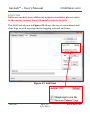
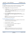
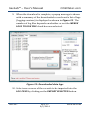
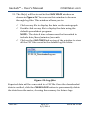
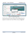
User’s Manual GasLab™ Sensor Configuration & Data Logging Software WARNING! Install this software before connecting your CO2Meter product(s) to your computer. Failure to do so may affect the ability for GasLab™ to detect your meter/sensor. If this happens, please follow the instructions shown in the “USB Driver Installation Instructions” section on page 37 of this manual. Rev.1.5 Software Version 2.0.6.73 www.co2meter.com Copyright © 2014 CO2 Meter, Inc. All Rights Reserved. GasLab™ – User’s Manual CO2Meter.com Table of Contents WELCOME ......................................................................................................................3 GASLAB™ SOFTWARE OVERVIEW ........................................................................4 MINIMUM SYSTEM REQUIREMENTS ...................................................................................... 4 SUPPORTED PRODUCTS............................................................................................................ 5 FEATURES AND ADVANTAGES................................................................................................. 5 GASLAB™ SOFTWARE INSTALLATION ................................................................6 CONNECTING THE SENSOR OR METER ...............................................................8 GASLAB™ MAIN SCREEN OVERVIEW ....................................................................9 INTERFACE .............................................................................................................................. 10 SENSOR SELECTION ............................................................................................................... 13 SENSOR COMMANDS .............................................................................................................. 16 COLLECTING DATA REAL-TIME USING GASLAB™ ........................................ 19 VIEWING LOG FILES ................................................................................................ 20 GRAPHING DATA IN REAL TIME ......................................................................... 21 CONFIGURE SENSOR ............................................................................................... 22 CALIBRATION TAB............................................................................................................ 23 OUTPUTS TAB ..................................................................................................................... 24 LOGS TAB............................................................................................................................... 26 DOWNLOADING LOGS FROM METER................................................................................... 27 INFORMATION TAB .......................................................................................................... 33 RAW DATA STREAM ............................................................................................... 34 CUSTOM PACKETS (AUTO-CHECKSUM) .............................................................................. 35 TROUBLESHOOTING GUIDE................................................................................. 36 USB DRIVER INSTALLATION INSTRUCTIONS .................................................................... 37 SUPPORT .................................................................................................................... 38 LIABILITY ................................................................................................................... 38 USR-007 REV.1.5 8/5/2014 PAGE 2 of 39 GasLab™ – User’s Manual CO2Meter.com Welcome Thank you for purchasing our meter/sensor and for downloading our GasLab™ software. CO2Meter, Inc. is a Florida based business specializing in the design and manufacturing of gas detection and monitoring devices – mainly CO2. Our approach is one based in the science of gas and how best to accurately and repeatedly measure that gas for the end users purposes. Our business partners in agriculture, HVAC, science, safety, research, pharmaceuticals, beverage, and other fields find our devices to be highly accurate and cost effective. We approach each customer’s application as a unique opportunity to understand, educate, and provide product solutions that meet the customers’ needs while exceeding their expectations for reliability and service. Our continued product innovation in combination with our “customer first” focus allows CO2Meter, Inc. to continue to provide solutions for the future. CO2Meter, Inc. is committed to the success of our customers; the health, welfare, and prosperity of our talented employees; and the continued development of our local community. CO2Meter, Inc. appreciates your business and looks forward to working with you and your team in the future. Please take some time to read through this manual in order to become familiar with this software. Also, please read the user’s manual for the meter or sensor you acquired and pay special attention to the important safeguards shown on those manuals. Before you install our software, please pay special attention to the system requirements shown on the next page. USR-007 REV.1.5 8/5/2014 PAGE 3 of 39 GasLab™ – User’s Manual CO2Meter.com GasLab™ Software Overview GasLab™ is CO2Meter's own in-house developed, fully-featured sensor configuration and data management software. GasLab™ allows you to view data read by CO2meter products in real-time with a user-friendly graphical interface. It can be used to configure sensors, view data in real-time, manage logs stored in meters fitted with internal memory and export data to spreadsheets. Never before has configuring, calibrating, and collecting data from CO2Meter’s products been so easy. Be sure to visit our website at www.co2meter.com regularly to download the latest GasLab™ software updates. Minimum System Requirements To utilize our complimentary software, your computer must meet or exceed the following minimum requirements: 1GHz processor with 1GB RAM, 1GB free disk space (2GB free disk space for 64-bit systems). Windows XP*/7/8/8.1 with Microsoft .NET Framework 4.0** or later. On Intel-based Mac computers, DAS software can run using a Windows 7/8 virtual machine software such as VMware Fusion® or similar. *Microsoft .NET is not supported on Media Center or Tablet editions. **Installer will optionally install .NET Framework. USR-007 REV.1.5 8/5/2014 PAGE 4 of 39 GasLab™ – User’s Manual CO2Meter.com Supported Products The following products can be used with GasLab™: K30/K33 Data Loggers K30/K33 Sensor Development Kits COZIR, Ambient and SPRINTIR Sensors Oxygen ZR250 series CH4-CO2 combination sensors Probes 1%, 30% and 100% AQ100 Units RS485 MODBUS strings and clusters 1%, 30%, 100% Sampling Meters and Data Loggers G-Series S8 mini sensors CM-1000 Series MHZ-CO2 sensors UV-Flux O2 Sensor pSense portable meter VOC sensors Features and Advantages Using GasLab™ will allow you to: Collect Data Real-time - Use this feature to capture data from the sensor in real-time, while the sensor or meter is connected to your computer. Auto-FTP – Use this feature to automatically update the log file(s) on an FTP server at a designated interval (default is set to 30 minutes). Enter the FTP path and the necessary credentials, then select an interval and click start. This is useful for monitoring measurements at a remote location. USR-007 REV.1.5 8/5/2014 PAGE 5 of 39 GasLab™ – User’s Manual CO2Meter.com Manage Logs – If your meter has data logging capabilities, use this feature to download a specific log or all currently stored in the meter’s internal memory. You can save and delete logs from the meter as well. Configure Sensor – Use this feature to launch a productspecific screen that will give you configuration parameters and allow you to perform tasks such as: Adjust logging intervals (if logging-capable) Calibrate the Sensor - access product-specific calibration options and perform sensor calibrations. Configure Outputs – establish parameters used by the outputs that are controlled by your meter/sensor, if any. Review meter/sensor information and status Manage Sensor and Logging Session – Select your CO2Meter product, sensor options and desired logging session options right at the main screen. GasLab™ Software Installation Visit www.co2meter.com/pages/downloads to download our complimentary GasLab™ software to your computer. IMPORTANT: INSTALL SOFTWARE FIRST BEFORE CONNECTING METER OR SENSOR TO YOUR COMPUTER. Install the GasLab™ software first to ensure that the proper driver, necessary for the meter/sensor, is installed on your computer before connecting the meter. USR-007 REV.1.5 8/5/2014 PAGE 6 of 39 GasLab™ – User’s Manual CO2Meter.com Click on the Install Now link and then select Run when prompted by the browser as shown in Figure 1. Figure 1: Download GasLab™ online (Internet Explorer 11 shown) Follow the steps and instructions prompted by your computer’s operating system. Make sure you have administrator privileges in order to install this program. USR-007 REV.1.5 8/5/2014 PAGE 7 of 39 GasLab™ – User’s Manual CO2Meter.com Connecting the Sensor or Meter IMPORTANT: INSTALL SOFTWARE FIRST BEFORE CONNECTING METER OR SENSOR TO YOUR COMPUTER. After GasLab™ software installation is completed, connect your meter/sensor to your computer using the provided data cable, typically a USB connector. The first time the meter/sensor is connected to the computer, the operating system will install the necessary USB drivers as shown in Figure 2. This process may take several minutes while windows installs the necessary drivers. Figure 2: USB driver installation Once the necessary meter/sensor drivers have been installed, your CO2Meter product is ready to use. Launch the GasLab™ software if it is not opened yet. USR-007 REV.1.5 8/5/2014 PAGE 8 of 39 GasLab™ – User’s Manual CO2Meter.com GasLab™ Main Screen Overview Data Tree Navigation Tabs (see Figure 9) (see Figure 8) Print Graph Button Real-Time Graph Section Figure 3: GasLab™ main screen Sensor Select Configure Section Sensor (see Figure 4) Button Selected Sensor Checkbox Sensor Commands Section Log Files Section (see Figure 7) Auto-Logging Section (see Figure 6) (see Figure 5) USR-007 REV.1.5 8/5/2014 PAGE 9 of 39 GasLab™ – User’s Manual CO2Meter.com Interface The GasLab™ interface has various areas or sections that you should familiarize with before using the software. A brief description of each section is shown below, along with their respective screenshots. A CO2Meter 30% CO2 data logger (CM-0019) is being used on the all images below. A more detailed description of the first two sections is shown on the chapters ahead for your convenience. Figure 4: Sensor Select section Sensor Select Section This section allows you to select the CO2Meter product to use with GasLab™. Simply select the port assigned to your connected sensor or meter and the product part number from their respective dropdown menus, then name it if desired and click on the CONNECT button. Connected Products List USR-007 REV.1.5 8/5/2014 PAGE 10 of 39 GasLab™ – User’s Manual CO2Meter.com Sensor Commands Section This section allows you to select the inputs you want to read from your CO2Meter product(s) to be displayed in the Real-Time graph. It also allows you to choose the units of measure of your preference. Simply on the Figure 5: Sensor Commands section desired input button once to activate it and then again to deactivate it. Figure 6: Auto-Logging section USR-007 REV.1.5 8/5/2014 Auto-Logging Section This section allows you to select the logging settings on each CO2Meter product connected to your computer. Simply select the desired logging interval, the session length, and their respective units and then click on the START LOGGING button. The CLEAR DATA button allows you to clear the Real-Time graph. PAGE 11 of 39 GasLab™ – User’s Manual CO2Meter.com Log Files Section This section allows you to select the available log files, open them in the default spreadsheet program, and manage all files. Figure 7: Log Files section Figure 8: Navigation tabs Figure 9: Data Tree section USR-007 REV.1.5 8/5/2014 Navigation Tabs Section This section allows you to navigate through the main screens of this software. Data Tree Section Displays the current reading, average (mean), minimum, and maximum of each type of data being monitored. The Data Tree allows you to see actual numbers, unaffected by scales. Minimum and maximum values help monitor anomalies in readings. PAGE 12 of 39 GasLab™ – User’s Manual CO2Meter.com Sensor Selection The Sensor Select section is located on the bottom left area of the GasLab™ main screen, as shown in Figure 3. The information entered in this section allows GasLab™ to recognize your meter/sensor to ensure proper functionality. This information is based on your CO2Meter product but ultimately, GasLab™ is designed to read sensors, whether standalone (sensor module only) or integrated in one of our meters. Below, a description of each of the fields used to collect information about your CO2Meter product on this section. Port – select the port your sensor is using from the dropdown menu. If multiple sensors are connected to your computer simultaneously and you are unsure about which port belongs to which sensor, you can verify it by simply disconnecting the sensor of interest from your computer and checking the dropdown menu to find out which port is no longer listed. The port that was related to the disconnected sensor will be automatically removed from the dropdown list. You can then connect the sensor back to your computer and select that port. Product – select your CO2Meter product part number from the dropdown menu as shown in Figure 10. You can find this number on the product label, typically located on the back of our meters. Figure 11 below shows a product label for a 100% DataLogger meter with part number CM-0003. Alternatively, you may select the sensor Series and Model from the individual fields below. USR-007 REV.1.5 8/5/2014 PAGE 13 of 39 GasLab™ – User’s Manual CO2Meter.com Figure 11: Product label example Figure 10: Product dropdown menu – P/N list Series – if you selected a part number on the Product field above, then the proper sensor series is populated automatically. Alternatively, you can select the sensor series from this dropdown menu, as shown in Figure 12 below. Figure 12: Series dropdown menu USR-007 REV.1.5 8/5/2014 PAGE 14 of 39 GasLab™ – User’s Manual CO2Meter.com Model – if you selected a part number on the Product field above, then the proper sensor model is populated automatically. Alternatively, you can select the model number of your sensor from this dropdown menu, as shown in Figure 13 below. Figure 13: Model dropdown menu NOTE: If you can’t find your CO2Meter product listed under the Product field and do not know which sensor series to choose, you can either select a different product that you know for certain has the same sensor your meter has or you can contact our customer support specialists at (386) 256-4910 for assistance. Sensor Name – type the desired sensor name in the Name box. This information will be used by GasLab™ as a unique identifier shown on the real-time graph and product list. The default name is “sensorn”, where n is a sequential number added automatically by the GasLab™ software. For example, Figure 4 shows a sensor being added for COM1, which was automatically named as “sensor1” by the GasLab™ software, while the product list shows a connected sensor named “DL_01”. USR-007 REV.1.5 8/5/2014 PAGE 15 of 39 GasLab™ – User’s Manual CO2Meter.com In order to successfully specify a sensor, you are required to make selections for the Port field and either the Product field or the Series and the Model fields. Once the required information has been added, a description of the sensor will appear in the product list area (white box) as shown in Figure 4. Finally click on the CONNECT button to access your sensor using the GasLab™ software. If multiple sensors are connected to your computer simultaneously, add them to the product list one at time by repeating the procedure described on the previous paragraph. You will be able to select each individual connected sensor from the product list. The real-time graph shows the data being collected by the sensor currently selected (highlighted blue). If you want to show multiple sensors on the real-time graph simultaneously, simply uncheck the ONLY SHOW SELECTED SENSOR checkbox shown in Figure 3. Sensor Commands The Sensor Commands section is located on the bottom mid area of the GasLab™ main screen, as shown in Figure 3. Here you can control the inputs available in your CO2Meter product by selecting the type of data to be displayed in the graph at any given time. NOTE: If an input button is grayed out, that particular input is not available for the sensor selected because that particular CO2Meter product is not fitted to read that specific type of data. USR-007 REV.1.5 8/5/2014 PAGE 16 of 39 GasLab™ – User’s Manual CO2Meter.com Each input has its own READ button, as shown in Figure 5. To receive readings from the sensor manually, click on the READ button of the desired input. This will allow you to confirm that the sensor is responding to the software command and is connected to your computer properly. Figure 14 below shows an example of a graph containing data points for each of that particular sensor’s inputs: CO2, Temperature, and Humidity. Figure 14: Example graph of single data point per input The values read by your sensor can be displayed either in real-time graphically using the GRAPH tab or in raw format listed using the DATA STREAM tab. USR-007 REV.1.5 8/5/2014 PAGE 17 of 39 GasLab™ – User’s Manual CO2Meter.com The GasLab™ software provides some options for units of measure displayed on the graph, as shown in Figure 5. These options are: CO2 concentration: Parts per million (PPM), or Percentage (%) Temperature: Degrees Celsius (°C), or Degrees Fahrenheit (°F) NOTE: Relative humidity is always displayed in percentage (%). USR-007 REV.1.5 8/5/2014 PAGE 18 of 39 GasLab™ – User’s Manual CO2Meter.com Collecting Data Real-time Using GasLab™ When a CO2Meter product is connected to the GasLab™ software, the main screen allows the user to auto-log in real-time. In the bottom right portion of the screen as shown in Figure 15, you can select how often and for what period of time to log data in realtime using the software. Figure 15: Auto-Logging NOTES: 1. When using this option, the data will be saved automatically as a CSV file that can be exported to Excel, Notepad, or Word. 2. Data can be collected from multiple meters simultaneously or individually, all saved in the same CSV file. USR-007 REV.1.5 8/5/2014 PAGE 19 of 39 GasLab™ – User’s Manual CO2Meter.com Viewing Log Files A list of available CSV files is shown on the bottom right section of the main screen, as shown in Figure 16. The following options are available: Click any file to display the data on the main graph. Double click on any file to display the data using the default spreadsheet program. Click on the LOG FILES link on top of the window to view all the CSV files saved in the default log file folder. Figure 16: Log files list USR-007 REV.1.5 8/5/2014 PAGE 20 of 39 GasLab™ – User’s Manual CO2Meter.com Graphing Data in Real Time The GRAPH tab allows you to see the values as the sensor(s) collected data, which will automatically be graphed showing the CO2 levels in ppm or %, Temperature in Celsius or Fahrenheit and Relative Humidity in % for all sensors in real time. NOTE: Data availability based on meter/sensor. Uncheck the ONLY SHOW SELECTED SENSOR checkbox (as shown in Figure 16) to see all data for all connected sensors (Figure 18) or leave it checked to see one sensor at a time (Figure 17). Figure 17: One sensor only USR-007 REV.1.5 8/5/2014 PAGE 21 of 39 GasLab™ – User’s Manual CO2Meter.com Figure 18: Multiple sensors Configure Sensor Selecting the CONFIGURE SENSOR button, the user can access the following tabs in order to: • • • • CALIBRATION tab: - Calibrate the sensor to Zero, 400ppm, or Span. - Turn ABC (Automatic Background Calibration) ON or OFF and set time as needed. OUTPUTS tab – Customize outputs and parameters, depending on model of meter/sensor, such as the LCD display, relay, alarm, pump and heartbeat interval, and data logging. LOGS tab – Download data logs. INFORMATION tab – Set the ModBus address. USR-007 REV.1.5 8/5/2014 PAGE 22 of 39 GasLab™ – User’s Manual CO2Meter.com CALIBRATION Tab The CALIBRATION tab is different for each sensor and Figure 19 shows the calibration tab for our 30% CO2 Data Logger CM-0019. To calibrate the sensor, follow the instructions that the software provides. Sensors can be calibrated at 000 ppm CO2 with 100% Nitrogen gas, a known CO2 concentration (usually 400ppm CO2 in outdoor air) or any know CO2 calibration gas. Figure 19: Calibration tab USR-007 REV.1.5 8/5/2014 PAGE 23 of 39 GasLab™ – User’s Manual CO2Meter.com OUTPUTS Tab Different models have different outputs available; please refer to the meter/sensor User’s Manual for more details. Some sensors have configurable outputs that can be used to control other devices such as relays and alarms. The settings for these can be changed based on needs. The basic parameters are the Output, Input, Low Limit, High Limit, and Shape. • • • OUTPUT simply selects which output is affected if there is more than one. INPUT sets which measurement controls the output. This will vary based on meter/sensor. LOW LIMIT and HIGH LIMIT determine the levels at which the output changes and how it changes. USR-007 REV.1.5 8/5/2014 PAGE 24 of 39 GasLab™ – User’s Manual CO2Meter.com As an example, as shown in Figure 20, a K-33 sensor can trigger an LED output using the CO2 level as the input, which will be turned ON when the CO2 level is above 2,000 ppm and it will be turned OFF when the CO2 level is below 1,500 ppm. As changes are made to the available settings, the text box on the right will provide an immediate description of how the selected output will function. Figure 20: OUTPUTS tab USR-007 REV.1.5 8/5/2014 PAGE 25 of 39 GasLab™ – User’s Manual CO2Meter.com LOGS Tab Different models have different outputs available; please refer to the meter/sensor User’s Manual for more details. The LOGS tab shown in Figure 21 allows the user to download and clear logs as well as program the logging interval and time. Figure 21: LOGS tab USR-007 REV.1.5 8/5/2014 PAGE 26 of 39 GasLab™ – User’s Manual CO2Meter.com Log Setup For optimal performance and accurate data collection it is highly recommend to program the meter before collecting data. Refer to Figure 21 for the appropriate buttons: 1. CLEAR LOGS: Clear all the old data from the meters memory. NOTE: RECOVER DELETED LOGS option is not operational on some models. 2. Device time SET: Synchronize date and time zone. 3. Interval SET: Set the data logging interval in seconds at the desired rate NOTE: This will affect the battery life and time to fill the internal memory of the meter. Downloading Logs from Meter 1. Connect the meter/sensor to the computer as instructed in the meter/sensor’s User’s Manual. 2. Launch GasLab™ software. 3. Follow the Sensor Select procedure on page 13. 4. Go to CONFIGURE SENSOR. 5. Select the LOGS tab. NOTE: Downloading logs may take several minutes, depending on the meter/sensor and transfer speed. USR-007 REV.1.5 8/5/2014 PAGE 27 of 39 GasLab™ – User’s Manual CO2Meter.com 6. If your meter has a START LOGGING switch, then the JUMPER status must be shown as OFF, as shown in Figure 21, indicating that this switch is in the OFF position. If the JUMPER status is ON, verify that the START LOGGING switch on your meter is in the correct position and click REFRESH on the LOGS tab. If your meter doesn’t have a START LOGGING switch, then the jumper status is not shown. NOTE: You may only download data when the START LOGGING switch is in the OFF position. 7. Selecting the MERGE LOGS TO ONE FILE check box, as shown in Figure 21, will allow for the various data log files to be downloaded into a single CSV file. 8. The GET LOGS button will initiate the download process. USR-007 REV.1.5 8/5/2014 PAGE 28 of 39 GasLab™ – User’s Manual CO2Meter.com 9. When the download is complete, a popup message is shown with a summary of the downloaded records and a list of logs (logging sessions) is displayed as shown in Figure 22. The number of log files depends on whether or not the MERGE LOGS TO ONE FILE check box was selected. Figure 22: Downloaded data logs 10. Select one or more of the records to be imported into the LOG FILES by clicking on the IMPORT SELECTED button. USR-007 REV.1.5 8/5/2014 PAGE 29 of 39 GasLab™ – User’s Manual CO2Meter.com 11. When completed, the file location will be displayed as shown in Figure 23. Click OK to continue. Figure 23: Log files location 12. Close the CONFIGURE SENSOR window to continue. USR-007 REV.1.5 8/5/2014 PAGE 30 of 39 GasLab™ – User’s Manual CO2Meter.com 13. The file(s) will be stored in the LOGS FILES window as shown in Figure 24. You can use this window to browse through log files. This window allows you to: Click on any file to display the data on the main graph. Double click on any file to display the data using the default spreadsheet program. NOTE: The date & time column must be formatted to include date/hour/minutes/seconds. Click on the LOG FILES link on top of the window to view all the CSV files saved in the default log file folder. Figure 24: Log files Exported data will be converted to a CSV file. Once the downloaded data is verified, click the CLEAR LOGS button to permanently delete the data from the meter, clearing the memory for future logs. USR-007 REV.1.5 8/5/2014 PAGE 31 of 39 GasLab™ – User’s Manual CO2Meter.com Figure 25: Append log prompt Each time that you start a new log, the software will prompt you to ask you if you want to continue using the same CSV file in order to append it or instead create a new CSV file, as shown in Figure 25. USR-007 REV.1.5 8/5/2014 PAGE 32 of 39 GasLab™ – User’s Manual CO2Meter.com INFORMATION Tab The INFORMATION tab, as shown in Figure 26, provides the user with the capability of: Setting the BUS ADDRESS Viewing the MAP ID Viewing the Meter SERIAL number Confirming the BATTERY gauge status Figure 26: INFORMATION tab USR-007 REV.1.5 8/5/2014 PAGE 33 of 39 GasLab™ – User’s Manual CO2Meter.com Raw Data Stream The DATA STREAM tab allows the user to see what the raw communication looks like between the sensor and the computer, as shown in Figure 27. It also has a section for sending custom packets of data to the sensor. NOTE: This function is only intended for users who have in-depth experience. Figure 27: Raw data stream USR-007 REV.1.5 8/5/2014 PAGE 34 of 39 GasLab™ – User’s Manual CO2Meter.com Custom Packets (auto-checksum) ***WARNING *** Sending custom packets could harm your sensor, voiding the warranty. Some sensors require a checksum or CRC to be added to each packet for verification. When AUTO-CHECKSUM is enabled, as shown in Figure 28, the software will automatically append a checksum to the end of the custom packet being sent. NOTE: This function is only intended for users who have in-depth experience. Figure 28: Custom packets AUTO-CHECKSUM USR-007 REV.1.5 8/5/2014 PAGE 35 of 39 GasLab™ – User’s Manual CO2Meter.com Troubleshooting Guide Symptom / Issue Meter/sensor is not recognized by computer/OS Possible Cause / Resolution The meter’s batteries might be depleted. Replace the batteries with fresh ones, or if applicable, connect the device to the included power supply. Also, USB driver installed in your computer might be wrong. See next USB Driver Installation Instructions section next. Device doesn’t Confirm the power adapter is connected power ON properly and that there is power in the outlet the adapter is connected to. Also confirm the appropriate voltage. If using batteries, make sure they are not depleted. The GasLab™ The version of the software may need to be software doesn’t updated. Update your software by visiting our start download webpage at http://www.co2meter.com/pages/downloads . Confirm your computer meets the minimum system requirements. Slow response Check the parameters of the meter and make sure the speed of the computer is adequate. Reading doesn’t Confirm the meter is correctly connected to the change computer. Make sure the START LOGGING switch on your meter is in the ON position. Meter/sensor is Your computer’s Windows operating system not shown in the (OS) may not have installed the appropriate PORT dropdown USB driver for your meter/sensor. Follow the menu instructions below to correct this issue. USR-007 REV.1.5 8/5/2014 PAGE 36 of 39 GasLab™ – User’s Manual CO2Meter.com USB Driver Installation Instructions To install the appropriate USB port drivers compatible with your meter/sensor, follow these steps: 1. Go to http://www.ftdichip.com/Drivers/VCP.htm and download the package appropriate for the version of Windows installed in your computer. 2. Move the file you downloaded to a location you can easily access. Make sure you have administrator priviledges. 3. Extract the file by right clicking on it and selecting extract here. 4. Go to your computer’s Device Manager in the Control Panel. For Windows 8, press the Windows key and 'x' at the same time to bring up the start menu then click on Device Manager. For Windows 7, open the start menu and type Device Manager in the search bar. 5. Find the Unrecognized USB Device in the list (it usually, but not always, has a yellow triangle icon). 6. Right click the Unrecognized USB Device item and select Update Driver Software. 7. Select Browse My Computer and point to the folder where you extracted the driver files to (step #3). This will install the necessary drivers to your computer and allow you to use your meter/sensor with GasLab™. If you have multiple sensors you should only have to perform this procedure once; the operating system will automatically find the driver for all the other sensors. USR-007 REV.1.5 8/5/2014 PAGE 37 of 39 GasLab™ – User’s Manual CO2Meter.com Support The quickest way to obtain technical support is via email. Please send all support inquires to [email protected]. Please include a clear, concise definition of the problem and any relevant troubleshooting information or steps taken so far, so we can duplicate the problem and quickly respond to your inquiry. Liability All liabilities under this agreement shall be limited to the actual cost of the product paid to CO2Meter.com. In no event shall CO2Meter.com be liable for any incidental or consequential damages, lost profits, loss of time, lost sales or loss or damage to data, injury to person or personal property or any other indirect damages as the result of use of our products. Contact Us We are here to help! For information or technical support, please contact us. [email protected] (386) 256-4910 ( Technical Support) (386) 872-7665 (Sales) www.co2meter.com Address: CO2Meter, Inc. 131 Business Center, A3 Ormond Beach, FL 32174 USA USR-007 REV.1.5 8/5/2014 PAGE 38 of 39 GasLab™ – User’s Manual CO2Meter.com NOTES: USR-007 REV.1.5 8/5/2014 PAGE 39 of 39