1
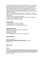
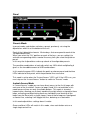
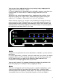
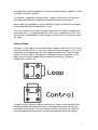
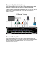
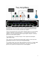
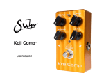
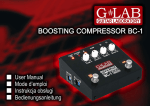
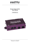
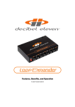
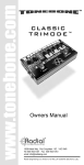
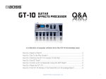
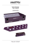
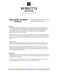
Loops in Chain
User Manual
Introduction
The product is a switcher that allows you to organize a very populated
pedalboard and facilitate effect changes rapidly in a live performance without so
much "tap dancing". It also allows more sophisticated applications so far only
available on MIDI equipment. This unit provides many possibilities without the
need for complex configurations and at a very affordable cost. Allows the use of
any effect pedal wether it is TrueByPass or not and the Loops in Chain turns it
automatically into TrueByPass.
It has the following features:
- 10 effect loops, any of which can be internally configured as amplifier control
lines or of any other device.
- 8 footswitches to select presets or patches
- 1 reset button to Truebypass whole unit
- 1 button which allows you to change the mode of operation
- 8 green LEDs indicating the preset or active loop
- 10 blue LEDs that indicate active loops/control lines
- 1 red LED indicates that the unit is powered
- 1 red LED indicates that the active mode is "Instant Access"
- 8 dipswitches each with 10 microkeys to set presets or patches (set of effects
or control lines which are activated to select the patch). Allows to have 8
configured presets and access to them from a single stomp.
- 2 modes of operation: patch selection (Presets) or effect selection (Instant
Access). Patch selection mode, changes the active patch to the new chosen
1
with a single stomp. Reset button turns off everything to stay in Truebypass. In
the effect selection mode, each of the 8 buttons selects a loop. If any loop is
configured as control line, it will operate the line. In this mode loops are
activated and deactivated by pressing and can build up those who are active.
The reset button turns off all active effects and control lines with a stomp.
-Optional output Buffer. Integrates a transparent buffer for the purpose to
connect long cables to the amplifier without affecting the signal. It can also be
disabled if not required.
-Muter. It includes an automatic circuit that mutes or attenuates the signal
during relays switching to reduce plop noise in the amplifier. You can disable it
from the panel.
-Anti-Bounce circuit for safe buttons operation.
-Pull-down resistors integrated in each loop. Avoids plop noise produced by
some effects when activated in the chain
-Aluminum cabinet with 2 mm thickness.
Connections
-Instrument input ¼” mono jack (6,35mm)
-Output to amplifier ¼” mono jack (6,35mm)
-Power jack: 9 Volts DC 2,1mm pin center negative
Optional add ons
Loop Cables: Y cable (Insert cable) for each stompbox.
Amplifier Effects loop cable
Single Control line cable
Double Control line cable
9V/ 1A Regulated power supply with center negative plug
Specifications
Power Supply: 9Vdc
Current draw: up to 450mA with all loops active.
Dimensions: 450x110x40mm(60mm tall including foot buttons)
Weight: 1225 gr.
Operation
Power
The unit has its own 9V power supply (optional), but is feasible to use an output
of a multiple power supply if so desired. The unit uses center negative plug. In
any case, it is recommended to use a same wall power outlet connector for all
effects and the amplifier to prevent ground loops that give rise to hum or buzz in
amplifier speakers.
2
Panel
Presets Mode
In preset mode, each button activates a preset, previously set using the
dipswitches which lie at the bottom of the unit.
Each of the 8 dipswitches boasts 10 microkeys that correspond to each of the
10 loops/control lines.
When you select the "On" position on each of the keys, you are setting it to
activate corresponding effect o control line every time you select that patch or
preset.
In this way the 8 dipswitches make up a bank of 8 configurable presets.
The possible combinations of each dip switch are 1024 which multiplied by 8
gives us the incredible amount of 8192 combinations.
In this mode the green LEDs indicate the patch or chosen preset and the blue
LEDs indicate for that patch, which loops/control lines are active.
This mode is active when the "Instant Access" LED is off. If the LED is on, you
must step on the “Instant Access” button to switch to "Presets" mode
Instant Access Mode
In "Instant Access" mode you can have direct access to the first 8 loops with
each one of the 8 switches. Access to loops 9 and 10 is not available in this
mode because there are only 8 available buttons. This mode is aimed at
improvisation, allowing you to freely combine the eight effects assigned to these
loops, activating and deactivating each one individually and clearing all the
loops from the Reset with a single stomp. If one of those loops was configured
as control line, selecting it will toggle that line, behaving as a footswitch.
In this mode dipswitches settings doesn’t matter.
Green and blue LEDs will match in this mode, since each button acts on a
single loop/ control line.
3
You can pass from mode to the other at any time by simply stepping on the
mode "Presets/Instant Access" button
In Presets mode the last selected preset is retained in memory, even when you
change mode. In "Instant Access" mode, changing mode will reset the
selection.
Whatever is the state of loops/control lines, stepping on the reset key, turns
them all off, both in the Instant Access mode and Preset mode, leaving the
audio line in TrueBypass. Powered off unit is also in TrueBypass.
Effects order of sequence is set when it was decided in what loop to connect
each one and it is fixed. Although there isn’t a prestablished effects order it is
recommended to always put delay and modulation effects after overdrive and
distortion effects. Also if the amplifier has an effects loop it is recommended to
put modulation and delay effects in this loop.
Buffer
Integrates an output buffer that can be disabled or enabled at any time from the
panel lever.
It is a unity gain buffer, so it keeps same level and tone, it only lowers the output
impedance of the unit. This allows the guitar to only "see" the input cable and
not the output cable, thus lowering the capacitive load imposed on the
microphones and keeping guitars tone crystal clear.
You can easily check if this changes the tone by changing the position of the
lever while playing in TrueByPass State (stepping on reset)
Muter
This circuit is triggered each time that you press a pedal and produces a very
short time attenuation in the output signal to avoid relay’s switching "plop"
spreading towards the amplifier. These "plops" can occur for many reasons. In
some pedals there are internal electrolyte capacitors which are loaded at
4
activating them and this produces a transient load resulting in a powerful "click"
or "plop" in amplifier speakers.
To avoid this, regardless of Muter circuit, Loops in Chain has a resistors on
each loop that keep these capacitors loaded to prevent that transient.
Noisy switching stompboxes can be identified using the Instant Access mode
activating one by one to diagnose this issue.
In any case Muter circuit helps to reduce the level of the "plop" and does not
alter signal tone. It is implemented with a FET that is completely cut off in the
normal state, and produces a short enough (less than 10 ms) cut to mask only
the “plop”.
Control Lines
All Loops in Chain ports can be configured as loops or control lines. For this it’s
necessary to open the unit, since this is done via internal jumpers (J14 to J23)
located on the analog board near each loop connection jack. There are two
jumpers for each loop, if the jumpers are placed vertically, that port is set to
loop, and on the other hand if they are placed horizontally, that port is
configured as control line.
To open the unit, you only need to remove the 4 screws of the top half of the
cabinet and open carefully both halves, taking particular care that both are
linked by internal wiring. Then you need to remove all the jack nuts and the
three analog board fixing screws to remove the board and set the jumpers.
5
The control lines are used to modify by means of a footswitch any feature of an
amplifier, which can be: channel, power, Reverb, etc. With Loops in Chain there
no need for an amp FSW, Loops in Chain can operate that line every time the
patch says so or in Instant Access mode if the line was set within the first 8
ports.
Factory setting is such that ports 1 to 8 are configured as loops and ports 9 and
10 are configured as control lines except customer express request at purchase
time.
If an effect is not activated when you select it in a particular port, and it works if
you plug it in other ports, it is likely that that port has been configured as control
line.
To activate a control line the Loops in Chain closes a contact linking two cable
wires. To disable the line that contact is open. To avoid ground loops this
contact is made between tip and ring terminals in Loops in chain jacks.
Cables
Y Cable: the cable required for each loop is a shielded stereo cable that has a
¼ " stereo plug on one end and two ¼" mono plugs on the other. Stereo plug is
plugged into Loops in Chain’s loop jack and mono plugs are for effect’s In and
Out jacks or chosen effects chain.
Amplifier Effects loop cable: is a shielded stereo cable that has a ¼ " stereo
plug on one end and two ¼" mono plugs on the other. Stereo plug is plugged
into Loops in Chain designated loop’s jack and mono plugs are for amp’s Input
and EFX Send jacks.
Single control line cable is a mono cable that has a ¼" stereo plug on one end
and a ¼" mono plug on the other. The stereo plug is plugged into the
designated port on the Loops in Chain and the mono plugs to the footswitch
jack on the amplifier.
Double control line cable is a stereo cable that has two ¼" stereo plugs on one
end and a ¼" stereo plug on the other. The first stereo plugs are plugged into
the designated ports on the Loops in Chain and the single stereo plugs to the
footswitch jack on the amplifier
Setup examples
6
Example 1: Amplifier with effects loop
In the following diagram you can see how to make a connection where some
effects are at amplifier’s input and some are in amplifier’s effects loop
Loop 6 is amplifier’s preamp and should be always on. If you turn it off, you can
enter directly to amplifier’s power stage (EFX’s loop return) bypassing
amplifier’s preamp.
Example 2: Two Amplifiers
In the following diagram you can see how to make a connection where two
amplifiers are used. Loops in Chain allows to switch from an amplifier to another
by simply stepping on the appropriate patch, and set the effects chain
accordingly at the same time.
7
An amplifier is connected to Loops in Chain’s output jack and the other on a
particular loop, in this case loop 4. Each presets have designated the effects
and control lines which are to be used with each amplifier.
You can set up presets that use the effects attached in ports 5, 6 and 7 for both
amplifiers and effects connected to ports 1, 2 and 3 will only act on the left
amplifier. If we shift everything to connect right amplifier into port 1, all effects
will be accessible to both amplifiers.
The example gives us an idea of Loops in Chain’s potential to build quite
sophisticated setups.
Even a preset can be configured to operate both amplifiers at the same time
(providing the measures necessary to avoid ground loops).
This example shows how using a loop configured as control line, it bridges both
amplifier inputs to operate them simultaneously. In this way you can have
presets for A, presets for B and presets for A and B together.
8
INTRODUCTION
1
CONNECTIONS
2
OPTIONAL ADD ONS
2
SPECIFICATIONS
2
OPERATION
2
POWER
PANEL
PRESETS MODE
INSTANT ACCESS MODE
BUFFER
MUTER
CONTROL LINES
CABLES
2
3
3
3
4
4
5
6
SETUP EXAMPLES
6
EXAMPLE 1: AMPLIFIER WITH EFFECTS LOOP
EXAMPLE 2: TWO AMPLIFIERS
7
7
9