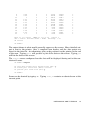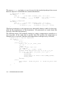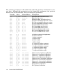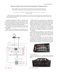
1
spec™ X-Ray Diffraction Software USER MANUAL and TUTORIALS REFERENCE MANUAL STANDARD MACROS GUIDE FOUR-CIRCLE REFERENCE ADMINISTRATOR’S GUIDE HARDWARE REFERENCE © 1989,1990,1992,1993,1994,1995,1996,1997,1998,1999,2000 by Certified Scientific Software. All rights reserved. Portions derived from appendices to the Doctoral thesis of Alan Braslau, Department of Physics, Harvard University, 1988. This is version 2.8 of the spec documentation, printed 3 June 2008, describing features of release 3.03 to 4.05 of the software. spec and C-PLOT are trademarks of Certified Scientific Software. All other trademarks and registered trademarks are the property of their respective owners. The material in this manual is furnished for informational use only, is subject to change without notice and should not be construed as a commitment by Certified Scientific Software. Certified Scientific Software assumes no responsibility or liability for any errors or inaccuracies that may appear in this manual. The software described in this manual is furnished under license and may only be used or copied in accordance with the terms of such license. spec X-Ray Diffraction Software Certified Scientific Software PO Box 390640 Cambridge, Massachusetts 02139 (617) 576-1610 (617) 497-4242 [email protected] FAX: http://www.certif.com MANUAL SUMMARY USER MANUAL and TUTORIALS A beginner’s guide to diffractometer operation and a tutorial on the basic features of the spec user interface. REFERENCE MANUAL An overview of the internal structure of spec and a complete description of all the built-in keywords, operators, grammar rules, commands and functions. STANDARD MACROS GUIDE Tips on writing macros, examples of macros from the standard library and a detailed description of the structure of the standard scan macros. FOUR-CIRCLE REFERENCE Describes the special functions, variables and macros used to operate the standard four-circle diffractometer. The various modes are described, along with the use of sectors, cut points and frozen angles. Also contains an explanation of how to fit the orientation matrix when the lattice parameters are unknown. ADMINISTRATOR’S GUIDE How to install and update the spec package. Explains the hardware configuration and motor settings file and how to use security features to protect motors from being moved by unqualified users. HARDWARE REFERENCE Information on the specific hardware devices and interfaces supported by spec. iv TABLE OF CONTENTS USER MANUAL AND TUTORIALS ........................................................... Introduction ......................................................................................... Beginner’s Guide to Diffractometer Operation ............................... Starting Up ...................................................................................... Using the Printer and Data Files ................................................... Setting Motor Positions and Moving Motors ................................ Counting ......................................................................................... Scans ............................................................................................... Introduction To the spec User Interface ............................................ spec as a Calculator ..................................................................... Command Recall (Histor y) .......................................................... Controlling Output To the Printer and Data Files ........................ Using Variables ............................................................................... Flow Control ................................................................................... Macro Facility ................................................................................. Command Files .............................................................................. Status and Help .............................................................................. UNIX Commands ........................................................................... Moving Motors ............................................................................... Diffractometer Geometry ............................................................. Counting ......................................................................................... CAMAC, GPIB and Serial .............................................................. Using spec with C-PLOT and Other UNIX Utilities .............................. Standard Data File Format ........................................................... Scans.4 ............................................................................................ Contents ......................................................................................... Showscans ...................................................................................... REFERENCE MANUAL .............................................................................. Introduction ......................................................................................... Internal Structure Of spec .................................................................. Syntax Description ............................................................................... Comments ...................................................................................... Identifiers ......................................................................................... v 1 3 4 4 6 7 11 12 14 14 15 17 18 20 22 25 26 27 28 31 32 34 35 35 36 40 41 43 45 45 46 46 46 Arrays .............................................................................................. Keywords ......................................................................................... Numeric Constants ........................................................................ String Constants ............................................................................. String Patterns and Wild Cards ..................................................... Command Recall (Histor y) .......................................................... Starting Up ...................................................................................... Keyboard Interrupts ....................................................................... Cleanup Macros ............................................................................ Exiting .............................................................................................. Variables ......................................................................................... Operators ....................................................................................... Flow Control ................................................................................... Grammar Rules .............................................................................. Built-In Functions and Commands .................................................... Utility Functions and Commands ................................................. Input and Output ........................................................................... Commands For Variables ............................................................. Commands For Macros ................................................................ Hardware Functions and Commands ......................................... Data Handling and Analysis Functions ........................................ String and Number Functions ....................................................... 47 48 49 49 50 50 51 54 54 55 55 59 62 64 68 69 81 89 90 94 106 118 STANDARD MACRO GUIDE .................................................................. 121 123 124 127 127 127 128 130 132 133 135 140 142 Introduction ......................................................................................... Some Tips ............................................................................................. Utility Macros ........................................................................................ UNIX Commands ........................................................................... Basic Aliases ................................................................................... Basic Utility Macros ........................................................................ Reading From Command Files ..................................................... Saving To Output Devices ............................................................. Start-up Macros ................................................................................... Motor Macros ...................................................................................... Counting Macros ................................................................................ Plotting Macros .................................................................................... vi Reciprocal Space Macros ................................................................. Scan Macros ........................................................................................ Scan Miscellany ............................................................................. Motor Scans ................................................................................... Basic Reciprocal Space Scans ..................................................... Special Reciprocal Space Scans ................................................. Temperature Scans ........................................................................ Powder Mode ................................................................................ Customizing Scan Output ............................................................. Temperature Control Macros ............................................................. Printer Initialization Macros ................................................................. The Scan Macros In Detail .................................................................. Standard Data-File Format ................................................................ 143 145 145 146 147 147 148 148 148 149 153 154 162 FOUR-CIRCLE REFERENCE ..................................................................... 163 165 166 168 169 172 173 174 175 175 177 178 179 180 Introduction ......................................................................................... Diffractometer Alignment .................................................................. Orientation Matrix ............................................................................... Four-Circle Modes ............................................................................... Freezing Angles ................................................................................... Sectors .................................................................................................. Cut Points ............................................................................................. Four-Circle Files .................................................................................... Four-Circle Variables ........................................................................... Four-Circle Functions ........................................................................... Four-Circle Macros .............................................................................. Zone Macros ........................................................................................ Least-Squares Refinement of Lattice Parameters ........................... ADMINISTRATOR’S GUIDE ...................................................................... Introduction ......................................................................................... Quick Install .......................................................................................... Steps For Installing spec ...................................................................... Extracting the Distribution ............................................................. Installing the spec Program Files .................................................. Installing Drivers .............................................................................. vii 185 187 187 187 188 189 193 Selecting the Hardware Configuration ....................................... Fine Tuning the Hardware Configuration .................................... Adding Site-Dependent Help Files ............................................... Adding Site-Dependent C Code ................................................. Updating spec ..................................................................................... Installed Files ........................................................................................ File Hierarchy .................................................................................. The CAMAC Debugging Program ............................................... Enabling I/O Ports On PC Platforms (not linux) .......................... Enabling I/O Ports On PC Platforms Running linux .................... Enabling E/ISA I/O Ports On HP 700 Systems ............................... The Configuration Editor ............................................................... The Settings File .............................................................................. The Config File ................................................................................ Security Issues ...................................................................................... Extra Protection .............................................................................. 194 195 195 195 197 198 198 199 200 200 201 202 203 203 210 210 HARDWARE REFERENCE ........................................................................ Introduction ......................................................................................... Interface Controllers and General Input/Output ............................ CAMAC Controllers ....................................................................... GPIB Controllers ............................................................................. VME Controllers .............................................................................. Serial (RS-232C) Ports ..................................................................... Generalized CAMAC I/O .............................................................. PC Port Input/Output .................................................................... Motor Controllers ................................................................................. Timers and Counters ........................................................................... Multichannel Data Acquisition Devices ........................................... 213 215 215 216 219 226 227 227 228 229 251 260 REFERENCES ............................................................................................... 267 INDEX ........................................................................................................... 268 MANUAL PAGE .......................................................................................... 279 viii Preface For the Interim Manual We apologize for the work-in-progress nature of this manual. We hope to have a completely up-to-date version someday in either this or the next century. Until then, we hope this version will be of some use. Presently, the Reference Manual and Administrator’s Guide included in this interim manual are more or less current with respect to release 4 of spec. Also, portions of the Four-Circle Reference have been recently rewritten. In addition, a new Hardware Reference has been started. However, the User Manual and Tutorials could use a major rewrite, and the Standard Macros Guide does not reflect many revisions to the standard macros. At any rate, this version of the manual should certainly give you the flavor of spec. For details on exactly how macros are constructed, you should probably consult the source code for the macros in your current distribution. The most recent on-line changes help files should be perused for the most up-to-date information on new features. Also, please note that our World Wide Web site at http://www.certif.com contains both online and downloadable PostScript copies of this manual, and will surely be updated with more interim versions, before the next official version is available. Finally, if there are questions or ambiguities that cannot otherwise be resolved, by all means contact us at CSS for the final word. Thanks for your patience. G.S. 6/13/99 Preface For the Interim Manual ix x Preface For the Interim Manual USER MANUAL AND TUTORIALS 2 USER MANUAL AND TUTORIALS Introduction spec is a UNIX-based software package for instrument control and data acquisition widely used for X-ray diffraction at synchrotrons around the world and in university, national and industrial laboratories. Developed in 1986 for X-ray diffraction experiments, spec’s portability, flexibility and power are winning it increasing application as general-purpose data-acquisition software. spec is available on a wide range of UNIX platforms and supports numerous hardware configurations. Features include: • Built-in code to regulate motor controllers and detection electronics using VME, CAMAC, GPIB, RS-232, PC-board and ethernet-socket interfaces. • Generalized access for VME, CAMAC, GPIB, RS-232, PC I/O ports and socket I/O to read from and write to user devices. • Sophisticated user interface with command interpreter, complete with variables, looping and flow control, allowing for creative experiment automation. • Language uses a familiar C-like syntax. • A command-file facility allows complicated or commonly used command sequences to be immediately called up. • An easy-to-use macro facility, with a large library of predefined macros. Macros can be readily modified with any text editor to suit experiments. • Scans, data-file formats, etc. are not built into the compiled program but defined as easily modified macros. • High-resolution, real-time data plots are available on X Windows and Sunview systems. • Macro libraries and geometry-calculation routines support two-, four-, five- and six-circle diffractometers, kappa diffractometers, many liquid surface X-ray diffractometers and other configurations. The standard four-circle diffractometer supports many advanced modes and includes features such as least-squares refinement of the lattice parameters. New geometry configurations can be easily created. • Hardware configuration employs a spread-sheet-style interface to select device names, addresses, CAMAC slot assignments, motor parameters, etc. • Security features let site administrators restrict access to particular motors (such as those at a synchrotron beam-line front end). • Available for most UNIX Systems, widely used on Linux PC platforms and UNIX workstations, including SUN (both SunOS 4.x and Solaris 2.x), HP 700 series and IBM RS/6000. USER MANUAL AND TUTORIALS 3 Beginner’s Guide to Diffractometer Operation Starting Up In this introduction to the basics of spec, as in most of this manual, the standard four-circle diffractometer configuration is used in the examples. Other specialized diffractometer geometries are available, but all configurations function in a similar manner. To start up the four-circle version of the spec package from a UNIX shell, type: % fourc (In this manual, input from the keyboard will be indicated in bold-faced type.) You will see output similar to the following: Welcome to ‘fourc’ Release 3.01.01 Copyright (c) 1987,1988,1989,1990,1991,1992,1993,1994,1995 by Certified Scientific Software. All rights reserved. (Portions derived from a program developed at Harvard University.) Using ‘/usr/local/lib/spec.d/’ for auxiliary file directory (SPECD). Getting configuration parameters from ‘SPECD/fourc/config’. Using ‘/dev/ca00’ for CAMAC device. Using National Instruments GPIB. Using 8 motors. = Spec Hot Line: (617) 576-1610. Type "h changes" for info on latest changes. See spec manual for tutorials. = Opening "SPECD/standard.mac" at input nest level 1. Warning: No open data file. Using "/dev/null". Type "startup" to initialize data file, etc. Opening "SPECD/four.mac" at input nest level 1. Warning: Using default lattice constants. (UB recalculated from orientation reflections and lattice.) 1.FOURC> The welcome message identifies the geometry configuration (fourc ) and the release number of the program (3.01.01 ). The directory name that contains spec’s auxil- 4 USER MANUAL AND TUTORIALS iary files is then identified (/usr/local/lib/spec.d ). That name is assigned to spec’s interval variable named SPECD . A configuration file is then read to obtain the hardware configuration (hardware devices and types, stepper motor parameters, etc.). Various messages are printed as the specific hardware devices are initialized. The number of motors described in the configuration file is reported. During the start-up hardware configuration, spec reads the current diffractometer angle settings from the motor-controller hardware registers and verifies that they agree with the positions stored in a settings file associated with the diffractometer. If there is a discrepancy, you will see output similar to the following: E500 at 0 steps (.1 user), spec at 24431 steps (12.3155 user) on motor 1, slot 6, "Theta". Modify the E500 registers? The E500 is one of many different motor controllers available. Since the controller shows 0 steps, it probably has been powered down, and the program value is probably correct. Type yes or y to modify the controller registers. If you are uncertain what to do, the safest thing is to immediately terminate the program without updating the motor settings files by typing the quit control character (usually a ˆV on IBM AIX platforms and a ˆ\ on most others), and then seek help. A news file is displayed each time the program starts up. In this example, the Spec Hot Line message is from that file. The spec administrator can keep the news file up-to-date with messages for local users. The first time you run spec, standard command files from the auxiliary file directory are automatically read (SPECD/four.mac and SPECD/standard.mac ). These files contain the standard macro definitions used to operate the diffractometer. There are also some commands that assign default values to the variables used in the macros. The displayed warning message about no data file being open is produced by these standard macros, along with the message that suggests running the startup macro. Finally, you are prompted for input. The prompt indicates the geometry configuration and includes a prepended command sequence number that is used with the command recall (or history) feature. You can exit the program by typing a ˆD (control-D) at the prompt: 1.FOURC> ˆD Bill’s state is stored for /dev/console. % The closing message confirms that your spec state is saved. The spec state consists of all your current macro definitions, variables, open output files and command history. Each user has a unique state associated with a particular terminal. Your saved state is automatically restored the next time you run spec from the same terminal. USER MANUAL AND TUTORIALS 5 (See page 52 in the Reference Manual to see how to start spec with a state from another user or terminal.) spec is built around an interpreter that has a C-like syntax and recognizes over a hundred built-in commands and function names. However, you will typically be invoking the standard macros. These macros are written to do specific jobs using the built-in commands and functions and require minimum keyboard input. If you just want to move motors, count photons and do scans, you will only have to learn the few standard macros presented in this Beginner’s Guide. Using the Printer and Data Files The standard macros in spec are designed to keep records of the experiment in progress on a printer and in a data file, although neither is required. The startup macro will prompt for a printer and a data file, along with asking for many other parameters and options. For now, enter information just for the printer and data file and accept the current values for the other parameters. 1.FOURC> startup Enter <return> for no change in the displayed parameters. The names of start-up macros that can be invoked separately are shown in parenthesis above a set of queries. Type ˆC to return to command level without finishing. (Interrupting one of the specialized start-up macros will likely undo any changes entered for its associated parameters.) (newsample) Title for scan headers (fourc)? cu 110 (newfile) Data file (/dev/null)? cu110/94_01_31.a Using "cu110/94_01_31.a". Next scan is number 1. Last scan # (0)? <return> Use a printer for scan output (NO)? y Printer device (/dev/null)? /dev/lp (And so on ...) 2.FOURC> When prompting for input, spec generally displays the default or current response in parentheses. Simply hitting <return> makes that selection. You can use the newfile macro directly to open (or reopen) a data file. Usage is newfile [ filename [ scan_number ] ] . (As is the convention in this manual, the square brackets indicate optional arguments, and the Courier Oblique typeface 6 USER MANUAL AND TUTORIALS denotes variable parameters you supply.) The optional argument scan_number is the number of the last scan and should be specified when appending to an existing data file. The standard spec macros allow you to use a printer to record scan data and other status information. Not all users use a printer, though, as the information is also stored in data files. When using a printer, spec generates output for a 132-column wide format. Most spec users use 8½" wide paper with their printer set to compressed mode. The initfx macro sends the correct programming sequence to put an Epson printer into compressed mode. The initdw macro does the same for a Decwriter. (Other macros are available for other printers − type lsdef init* from spec for a list.) You could also use printer switches to select compressed mode. Also, when using the printer, you should set the top-of-form position correctly. That way, each scan will begin at the top of a new page, and it will be much easier to locate scans when thumbing through the data printout later. Use the comment macro (also available as com ) to insert arbitrary comments in the data file and on the printer. For example, 2.FOURC> com Absorber inserted in front of detector Mon Feb 15 01:41:52 1994. Absorber inserted in front of detector. 3.FOURC> Setting Motor Positions and Moving Motors When spec is used to control an X-ray diffractometer, the wh (where) macro is available to show the positions of the most interesting angles and the diffractometer position in reciprocal space coordinates. With the four-circle diffractometer, the output is as follows: 3.FOURC> wh H K L = 0 0 1 Alpha = 30 Beta = 30 Azimuth = 90 Omega = 0 Lambda = 1.54 Two Theta 60.0000 Theta 30.0000 Chi -90.0000 Phi 0.0000 4.FOURC> The incident and scattered angles for surface diffraction (ALPHA and BETA ), the USER MANUAL AND TUTORIALS 7 AZIMUTH angle used in advanced modes (see the Four-Circle Reference) and the incident X-ray wavelength, LAMBDA , are also listed. The angular positions listed above are the user angles. You set user angles during diffractometer alignment to satisfy the premises of the geometry calculations, such as the positions of the zeroes of the angles. Dial angles keep track of hardware limits and prevent complete loss of angles from alignment errors or computer failure. The dial angles are generally made to agree with a physical indicator on each motor, such as a dial. User angles are related to the dial angles through the equation: user = sign × dial + offset Redefining a user angle changes the internal value of offset. Dial angles are directly proportional to the values contained in the hardware controller registers. The sign of motion is set in the configuration file by the spec administrator and normally isn’t changed. The set_dial motor position macro is used to set the dial position of a motor. The argument motor is the motor number or mnemonic. All motors have short mnemonics, such as tth , th , chi , and phi . 4.FOURC> set_dial tth 24.526 Mon Feb 15 01:42:10 1994. Two Theta dial reset from 0 to 24.526. 5.FOURC> The set motor position macro is used to set the user position of a motor (i.e., to change offset). If you had a slit motor with mnemonic ts1 , you might enter 5.FOURC> set ts1 .5 Mon Feb 15 01:43:31 1994. Top Slit1 reset from 0 to .5. 6.FOURC> The wa (where all) macro lists both the user and dial positions of all configured motors. 6.FOURC> wa Current Positions (user, dial) Two Theta Theta Chi tth th chi 24.6310 12.3155 90.0000 24.5260 12.2155 89.7865 7.FOURC> 8 USER MANUAL AND TUTORIALS Phi Top Slit1 Bot Slit1 phi ts1 bs1 0.0000 0.5000 -0.5000 0.0950 0.5000 -0.5000 spec also keeps track of software motor limits. These limits are always checked before any motors are moved. The lm macro lists these limits in both user and dial angles, as well as the current positions of the motors. 7.FOURC> lm USER Limits (high, current, low): Two Theta Theta Chi Phi Top Slit1 Bot Slit1 180.1050 90.1000 135.2135 179.9050 5.0000 0.0000 24.6310 12.3155 90.0000 0.0000 0.5000 -0.5000 -179.8950 -89.9000 -134.7865 -180.0950 0.0000 -5.0000 DIAL Limits (high, current, low): Two Theta Theta Chi Phi Top Slit1 Bot Slit1 180.0000 90.0000 135.0000 180.0000 5.0000 0.0000 24.5260 12.2155 89.7865 0.0950 0.5000 -0.5000 -180.0000 -90.0000 -135.0000 -180.0000 0.0000 -5.0000 8.FOURC> The macro set_lm motor low high changes the software limits for a single motor. The values for low and high are given in user angles (although they are stored internally in dial angles). The wm motor [ motor ... ] macro lists complete information for up to six motors given as arguments. 8.FOURC> wm tth th User High Current Low Dial High Current Low Two Theta tth Theta th 180.1050 24.6310 -179.8950 90.1000 12.3155 -89.9000 180.0000 24.5260 -180.0000 90.0000 12.2155 -90.0000 9.FOURC> Once the diffractometer has been aligned, you can move to any allowed reciprocal space position using the br H K L (Bragg) macro. USER MANUAL AND TUTORIALS 9 9.FOURC> br 2 0 0 10.FOURC> wh H = 2 K = 0 L = 0 ALPHA = -25.251 BETA = 25.251 Two Theta 50.5030 Theta 25.2515 Chi 90.0000 AZIMUTH = 90 LAMBDA = 1.54 Phi 0.0000 11.FOURC> You can see where the motors would move for particular values of ( H, K, L ) using the ca H K L (calculate) macro. 11.FOURC> ca 2 1 1 Calculated Positions: H = 2 K = 1 L = 1 ALPHA = -25.252 BETA = 25.252 Two Theta 62.9960 Theta 31.4980 Chi 54.7355 AZIMUTH = -90 LAMBDA = 1.54 Phi 135.0000 12.FOURC> Conversely, spec will display the (H, K, L ) that corresponds to a particular set of motor positions using the ci tth th chi phi (calculate inverse) macro. A single motor may be moved in real space using the mv motor position macro. For example, 12.FOURC> mv tth 50 13.FOURC> will move the 2θ motor to 50°. You are prompted for more input immediately, even though the motors are still moving. You can tell when the motor has stopped moving by using the w macro. The program will pause until the motor has stopped moving and then generate a beep on the terminal. Alternatively, you can have the motor position displayed on the screen as it is moving by invoking the umv (updated-move) macro instead of mv . To stop the motors before they have finished moving, type the interrupt character, usually a ˆC . You can use the mvr motor relative_position macro to move a motor relative to its current position. 10 USER MANUAL AND TUTORIALS 13.FOURC> mvr th 1 14.FOURC> will move θ by one degree. The tw motor delta (tweak) macro is useful when lining up the diffractometer or when searching for the beam. 14.FOURC> tw th .1 Indicate direction with + (or p) or - (or n) or enter new step size. Type something else (or ˆC) to quit. th th th th th th th = = = = = = = 26.2515, 26.3515, 26.4515, 26.5515, 26.6515, 26.5515, 26.4515, which which which which which which which way way way way way way way (+)? (+)? (+)? (+)? (+)? (-)? (-)? <return> <return> <return> <return> <return> ˆC 15.FOURC> Each time you hit <return> , the motor moves delta in the plus or minus direction. Counting You count photons using the ct macro. Without arguments, this macro counts for the time set by the variable COUNT , which is typically one second. According to the convention used in the standard macros, positive count times indicate counting to seconds and negative count times indicate counting to monitor counts. 15.FOURC> ct 10 Mon Feb 15 01:45:12 1994 Seconds = 10 Monitor = 389387 (38939/s) Detector = 192041 (19204/s) 16.FOURC> ct -40000 Mon Feb 15 01:45:28 1994 Seconds = 1.027 Monitor = 40000 (38948/s) Detector = 19756 (19237/s) 17.FOURC> USER MANUAL AND TUTORIALS 11 Type a ˆC to abort counting. The macro show_cnts will display the current scaler contents. The uct macro will update the screen with the current scaler contents during the counting period. Scans Scans in spec are built of macros. Many different standard scans are available. Absolute-position motor scans such as ascan , a2scan and a3scan move one, two or three motors at a time. Relative-position motor scans are lup (or dscan ), d2scan and d3scan . The relative-position scans all return the motors to their starting positions after the last point. Two motors can be scanned over a grid of points using the mesh scan. Simple reciprocal space scans are hscan , kscan and lscan . The hklscan macro moves the diffractometer along an arbitrary straight line in reciprocal space. Scans such as hkcircle or hkradial describe other trajectories. The hklmesh scan measures intensities over a grid of reciprocal-space points. If you do not know the arguments for a scan or how a scan is used, you can call up its usage by typing its name with no arguments. 17.FOURC> ascan Usage: ascan motor start finish intervals time 18.FOURC> hscan Usage: hscan start finish intervals time 19.FOURC> When the program does a scan such as hscan , the following happens: the program waits for motors to stop moving, calculates (H, K, L ) for the current position and then scans H, holding K and L fixed for a reciprocal space scan along the H direction. 19.FOURC> hscan .9 1.1 20 1 Mon Feb 15 01:50:33 1994 Scan 1 Mon Feb 15 01:50:33 1994 file = cu110/90_01_31.a hklscan 0.9 1.1 0 0 0 0 20 1 # H K L Detector Monitor Seconds 0 0.9 0 0 2604 38939 1 1 0.91 0 0 3822 38820 1 2 0.92 0 0 5295 39034 1 3 0.93 0 0 7259 38789 1 4 0.94 0 0 9298 38804 1 5 0.95 0 0 11505 38909 1 6 0.96 0 0 13907 38821 1 7 0.97 0 0 16022 39110 1 12 USER MANUAL AND TUTORIALS 8 9 10 11 12 13 14 15 16 17 18 19 20 0.98 0.99 1 1.01 1.02 1.03 1.04 1.05 1.06 1.07 1.08 1.09 1.1 0 0 0 0 0 0 0 0 0 0 0 0 0 0 0 0 0 0 0 0 0 0 0 0 0 0 17603 18834 19103 18701 17652 16011 13848 11585 9302 7237 5324 3780 2580 38839 38950 38917 39013 39135 38836 38901 38933 39022 39205 38957 38801 38975 1 1 1 1 1 1 1 1 1 1 1 1 1 Peak at 1 is 19103 FWHM at 1 is 0.05 COM is 1 Sum = 231272 Ave.Mon./Time = 38921 Ave.Temp. = 0C 28 second 20.FOURC> The output shown is what would generally appear on the screen. More detailed output is sent to the printer. Also, a complete scan header and the data points are stored in the data file. A rudimentary plot can be produced on the printer at the end of the scan. Typing splot will produce a plot of the data on the screen. Typing pts will list the data on the screen. The setplot macro configures how the data will be displayed during and at the conclusion of scans. 20.FOURC> setplot Do real-time screen plots during scans (NO)? y Do screen plot after scan (YES)? <return> Do printer plot after scan (NO)? y 21.FOURC> Scans can be aborted by typing ˆC . Typing scan_on restarts an aborted scan at the current point. USER MANUAL AND TUTORIALS 13 Introduction To the spec User Interface spec as a Calculator In some respects, the spec user interface behaves like a BASIC language interpreter that uses the C language syntax. For example, you can easily print strings and the results of arithmetic expressions: 1.FOURC> p 2+2, sqrt(3), "2ˆ16 =", 1<<16 4 1.73205 2ˆ16 = 65536 2.FOURC> (The p macro is defined as print , a built-in command.) You do not need to search for your calculator, as all the standard operators and functions are available. The arithmetic operators (= , ∗ , / , % , + , − , ++ , − − , += , −= , ∗= , /= , %= ), the relational operators (> , < , <= , >= , == , != ), the boolean operators (! , && , || ), the bitwise operators (>> , << , ˜ , & , ˆ , | , >>= , <<= , &= , ˆ= , |= ) and the ternary operator (? : ) are all available. Parentheses can be used for grouping within expressions. See the Reference Manual for a description of all the operators and their rules of precedence. The most useful standard C math functions are included, such as sin() , cos() , tan() , asin() , acos() , atan() , exp() , log() , log10() , pow() , sqrt() , and fabs() . Conversions functions such as deg() and rad() convert between degrees and radians, while bcd() and dcb() convert between decimal and binary-coded decimal. A rand() function to return random numbers is also provided. Numbers can be entered in decimal, octal or hexadecimal notation, just as in C. 2.FOURC> p 100, 0100, 0x100 100 64 256 3.FOURC> Special string functions also exist. The date() function provides the current date and time as a string: 3.FOURC> p date() Mon Feb 15 02:13:13 1994 4.FOURC> The date() function can also take an argument that is the number of seconds from the UNIX epoch. 14 USER MANUAL AND TUTORIALS 4.FOURC> p date(1e9) Sat Sep 8 21:46:40 2001 5.FOURC> p date(0) Wed Dec 31 19:00:00 1969 6.FOURC> p int(time()), date(time()) 729760917 Mon Feb 15 02:21:57 1994 7.FOURC> The second example shows the (Eastern Standard Time) moment of the UNIX epoch. The function time() returns the number of seconds since that moment, including a fractional part with a resolution determined by the system clock. The difference of subsequent calls to time() can, for example, give a reasonable elapsed time for each point in a scan. The function input() reads a string from the keyboard. An optional argument will be printed first. For example, a macro or command file might prompt you for information: 7.FOURC> TITLE = input("Please enter a title: Please enter a title: Au (001) Sample #1 ") 8.FOURC> Other string functions such as index() , substr() , length(s) and sprintf(format, [ args ]) are also available. See the Reference Manual for details. Command Recall (Histor y) A command recall (or history) feature lets you recall previously typed commands. spec’s command recall implements a subset of the features of the standard csh history mechanism. When using command recall, note that only keyboard input is saved, command recall cannot be used in command files, and the command recall characters must occur at the beginning of a new line. When you run spec interactively, a command sequence number is always prepended to the prompt. The history command lists by number the commands that can be recalled. (At present, only the most recent 1000 commands are available for recall.) USER MANUAL AND TUTORIALS 15 8.FOURC> history 1 p 2+2, sqrt(3), "2ˆ16 =", 1<<16 2 p 100, 0100, 0x100 3 p date() 4 p date(1e9) 5 p date(0) 6 p time(), date(time()) 7 TITLE = input("Please enter a title: 8 history ") 9.FOURC> To use command recall, type !! or !-1 to recall the previous command. Typing !-2 will recall the second previous command. Type !2 to recall command number 2. Also, !TI will recall the last command beginning with the string TI . 9.FOURC> !2 p 100, 0100, 0x100 100 64 256 10.FOURC> Notice that the recalled command is first printed and then executed. Recalled commands can be modified by appending text. 10.FOURC> !p , "= 100, 0100 and 0x100." p 100, 0100, 0x100 "= 100, 0100 and 0x100." 100 64 256 = 100, 0100 and 0x100. 11.FOURC> Arbitrary substitutions to recalled commands are allowed using the :s/left/right/ modifier, as in 11.FOURC> !-1:s/./,respectively./ p 100, 0100, 0x100 "= 100, 0100 and 0x100, respectively." 100 64 256 = 100, 0100 and 0x100, respectively. 12.FOURC> You can also use a circumflex ˆ to make a substitution on the most recent command, just as with the standard UNIX csh. 12.FOURC> ˆ=ˆareˆ p 100, 0100, 0x100 "are 100, 0100 and 0x100, respectively." 100 64 256 are 100, 0100 and 0x100, respectively. 13.FOURC> 16 USER MANUAL AND TUTORIALS Controlling Output To the Printer and Data Files spec’s output facility is unusual. Output files and devices, including the screen, are turned on or off for output. The output of each printing command, whether generated by a user command or internally, is sent to all the turned-on devices. open("filename") opens a file or device to append output. The current contents of existing files are never erased. The on("filename") function turns on printing to the file or device and opens the file if open() was not previously called. The off("filename") function ends printing to that file or device, and close("filename") closes the file or device and removes the name from the program’s table of file pointers. The name "tty" is special when used as an argument to these functions. It always refers to your current terminal. Whenever there is an error or a ˆC interrupt, all files (except log files) are turned off, and output to the terminal is turned on. A log file is used for debugging purposes and is any file that begins with log . Output to all on files and devices is automatically copied to a log file. To get the status of all open files, type: 13.FOURC> on() ‘tty’ has output ON. ‘/usr/alan/default.dat’ has output OFF. ‘/dev/null’ has output OFF. 14.FOURC> If you change spec’s current directory, you can reference open files either by the name with which the files were opened or by the correct path name relative to the new directory. The standard macros use three output devices: the screen, a printer and a data file. The ont , offt , onp , offp , ond and offd macros are usually used to simplify controlling output to these devices, where ont is defined as on("tty") , etc. Typical usage is ond; offt; printf("#S %d\n", ++SCAN_N); offd; ont Often, printing commands are placed between onp and offp to direct the output both to the screen and the printer. For instance, 1.FOURC> onp; p "This is also being printed on the printer."; offp This is also being printed on the printer. 2.FOURC> Formatted printing is available using the printf() and fprintf() functions. The USER MANUAL AND TUTORIALS 17 format specifications are the same as for the C-language routine and can be found in the printf() write-up in any C reference manual. 2.FOURC> printf("The square root of two is %.12g.\n", sqrt(2)) The square root of two is 1.41421356237. 3.FOURC> Using Variables spec’s variables can be used as both strings and as double-precision floating-point numbers. Variables are not declared, but come into existence through usage. Some variables are built-in, though, and of these, some have preassigned values. The variable PI is an example. 3.FOURC> { 4.more> k = 2 * PI / 1.54 5.more> print k 6.more> } 4.07999 7.FOURC> Curly brackets ({ and } ) are used to delimit a block to be interpreted together, since variables are local to interpreted blocks. Notice that the prompt indicates the program is expecting further input before interpreting and taking action. 7.FOURC> print k 0 8.FOURC> The value of k disappeared because k was local to the previous statement block. New variables start off with a value of zero. A variable may be declared global to hold its value outside an interpreted block: 8.FOURC> global Lambda CuKa 9.FOURC> Lambda = 1.54 10.FOURC> CuKa = "Copper K-alpha" 11.FOURC> print CuKa, "=", Lambda Copper K-alpha = 1.54 12.FOURC> 18 USER MANUAL AND TUTORIALS By convention, global variables in the standard macro package use capital letters or begin with an underscore. Variables can be made constant to protect them from accidental reassignment, 12.FOURC> constant Lambda 1.54 13.FOURC> Lambda = 1.7 Trying to assign to a constant ‘Lambda’. 14.FOURC> Variables defined as constant are automatically global. Most built-in variables with preassigned values are of the immutable type and cannot be changed at all: 14.FOURC> PI = 1 Trying to assign to an immutable ‘PI’. 15.FOURC> Some built-in variables, such as DEBUG , can be changed by the user. Another variable, the A[] array, may be filled by the program with the current motor positions or can be set to target motor positions. For a list of all current symbols, type: 15.FOURC> syms 8256 96 80 96 80 96 96 128 112 128 112 80 80 80 80 80 80 96 80 80 1296 96 80 80 80 ( Built-In/Global/Local Array Number String Constant/Immutable ) A (BA...) 80 SLIT_W (G.NS.) 80 _f1 ADMIN (G..S.) 96 SPEC (B..SI) 80 _f2 BG (G.N..) 112 SPECD (B..SI) 80 _f3 COLS (B.N..) 80 TEMP_CS (G.NS.) 80 _fx COUNT (G.N..) 80 TEMP_SP (G.NS.) 80 _g1 COUNTERS (B.N.I) 96 TERAMP_MIN (G.N..) 80 _g2 COUNT_TIME (G.NS.) 96 TERM (B..S.) 96 _hkl_col CP_FILTER (G..S.) 80 TIME (G.NS.) 80 _m CWD (B..SI) 96 TIME_END (G.NS.) 80 _m1 DATAFILE (G..S.) 96 TITLE (G..S.) 80 _m2 DATA_DIR (G..S.) 80 T_AV (G.NS.) 80 _m3 DATE (G.NS.) 80 T_HI_SP (G.N..) 80 _n1 DEBUG (B.N..) 80 T_L (G.NS.) 80 _n2 DEGC (G.NS.) 80 T_LO_SP (G.N..) 80 _nm DEGC_SP (G.NS.) 2736 U (BA...) 80 _numgeo DET (G.N..) 1056 UB (BA...) 80 _pmot DOFILE (G.NS.) 592 UNITS (GA...) 96 _pmotflag DO_DIR (G..S.) 80 UPDATE (G.N..) 96 _pre_chk EPOCH (G.N.C) 96 USER (B..SI) 80 _pwid FPRNT (G.NS.) 96 USER_CHK_ACQ (G.NS.) 80 _reg_f G (BA...) 96 USER_CHK_COUNT (G.NS.) 80 _reg_i GS_file (G..S.) 96 USER_CHK_MOVE (G.NS.) 80 _reg_n GS_scan (G.N..) 80 VFMT (G.NS.) 80 _reg_s GS_xcol (G.N..) 80 VPRNT (G.NS.) 112 _reg_scan GS_ycol (G.N..) 80 X_L (G.NS.) 80 _reg_t (G.NS.) (G.NS.) (G.NS.) (G.NS.) (G.NS.) (G.NS.) (G.N.C) (G.NS.) (G.NS.) (G.NS.) (G.NS.) (G.NS.) (G.NS.) (G.NS.) (G.N..) (G.NS.) (G.NS.) (G.N..) (G.NS.) (G.NS.) (G.NS.) (G.NS.) (G.NS.) (G..S.) (G.NS.) USER MANUAL AND TUTORIALS 19 96 GTERM (B..S.) 80 HEADING (G.NS.) 112 HOME (B..SI) 96 MAIL (G..S.) 80 MODES (G.N.C) 80 MON (G.N..) 96 MON_RATE (G.NS.) 80 MOTORS (B.N.I) 80 MT_AV (G.NS.) 80 NPTS (G.NS.) 80 PFMT (G.NS.) 80 PI (B.N.I) 96 PLOT_MODE (G.N..) 80 PL_G (G.N..) 80 PL_G1 (G.N..) 80 PL_X (G.N..) 80 PL_Y (G.N..) 80 PPRNT (G.NS.) 112 PRINTER (G..S.) 1856 Q (BA...) 80 REFLEX (G.NS.) 80 ROWS (B.N..) 10576 S (BA...) 80 SCAN_N (G.NS.) 80 SLIT_H (G.NS.) 80 SLIT_N (G.N.C) Memory usage is 41088 bytes. 80 816 80 80 80 80 80 80 80 80 80 80 96 80 80 80 80 80 80 80 80 80 80 80 80 80 Y_L Z _1 _2 _3 _4 _5 _6 _7 _8 _9 _LAMBDA _bad_lim _c1 _c2 _c3 _c4 _cols _const _cp _ctime _d _d1 _d2 _d3 _f (G.NS.) (BA...) (G.N..) (G.NS.) (G.NS.) (G.NS.) (G.NS.) (G.NS.) (G.NS.) (G.NS.) (G.NS.) (G.NS.) (G.NS.) (G.NS.) (G.NS.) (G.NS.) (G.NS.) (G.NS.) (G.NS.) (G.NS.) (G.NS.) (G.NS.) (G.NS.) (G.NS.) (G.NS.) (G.NS.) 80 80 80 80 80 80 80 80 96 80 80 80 80 96 80 1184 656 80 80 128 80 128 80 80 _s _s1 _s2 _s3 _sleep _stime _stype _sx _upd_flg bg_m bg_pts bg_yI chi chk_thresh det gmodes mA mon phi rplot_col sec splot_col th tth (G.NS.) (G.NS.) (G.NS.) (G.NS.) (G.NS.) (G.NS.) (G.NS.) (G.NS.) (G.NS.) (G.NS.) (G.N..) (G.NS.) (B.N.I) (G.NS.) (B.N.I) (GA...) (GA...) (B.N.I) (B.N.I) (G..S.) (B.N.I) (G..S.) (B.N.I) (B.N.I) 16.FOURC> The number preceding each name is the number of bytes of memory the variable consumes. All the global variables in the list above come from the standard start-up macro files. Those variables that begin with an underscore are internal to the standard macro package. Flow Control Flow control allows you to construct complex scans and other macros to control experiments and take data. The syntax of the flow control is very similar to standard C. For example, to list all the motor positions, you can use the following loop: 20 USER MANUAL AND TUTORIALS 16.FOURC> for (i = 0; i < MOTORS; i++) { 17.more> printf("Motor %d %-10s = %g\n", i, motor_name(i), A[i]) 18.more> } Motor 0 Two Theta = 3 Motor 1 Theta = 1.5 Motor 2 Chi = 0 Motor 3 Phi = 0 19.FOURC> As in C, the for statement contains within parentheses three optional expressions separated by semicolons. The first expression is executed before entering the loop. The second is the test done before each pass of the loop — if it evaluates false, the loop is terminated. The third expression is executed at the end of each loop. The conditional statements if ( condition ) statement and if ( condition ) statement else statement are also available. For example, to test whether a variable has been assigned a value, you could examine the return value of the built-in whatis() function (described on page 75 in the Reference Manual). 19.FOURC> if (whatis("DATAFILE")>>16&0x8000) 20.more> print "Warning, Data file is uninitialized!" 21.more> ; Warning, Data file is uninitialized! 22.FOURC> When there is a solitary if statement, a semicolon, extra newline or some other command must be read before the if statement will be executed, as it is not clear to the parser whether an else statement will follow. If there is an else statement, it must follow the if portion of the statement on the next line. 22.FOURC> if (whatis("DATAFILE")>>16&0x8000) 23.more> print "Warning, Data file is uninitialized!" 24.more> else 25.more> print "Data is being stored in", DATAFILE Data is being stored in /usr/alan/default.dat 26.FOURC> The while construction is also available. Usage is USER MANUAL AND TUTORIALS 21 26.FOURC> while (wait(0x22)) { 27.more> getangles 28.more> printf("%10.4f\r", A[tth]) 29.more> } 30.FOURC> As in C, continue and break statements may be used within loops. The statement exit can be used anywhere and always causes a jump back to the command level. Macro Facility One of spec’s most powerful features is its provision for defining macros. Through macros, you can simplify use of the diffractometer as well as determine the style and format of the data output. Through the macro facility, you can customize the environment to include any enhancements or specialized requirements for your experiment. Standard macro sets included in the spec package support conventional twocircle, four-circle and z-axis diffractometers along with some specialized liquid surface diffractometers. These macros control the measurement and the recording of experimental data and establish a standard format for ASCII data files. An example of a simple macro that can be used to record a comment on the printer is 30.FOURC> def com ’ 31.quot> on(PRINTER) 32.quot> printf("$*\n") 33.quot> off(PRINTER) 34.quot> ’ 35.FOURC> Notice the prompt shows the program is expecting the quote to be closed. The variable PRINTER contains a string naming the printer device used to document the diffractometer operation. To use the above macro, type: 35.FOURC> com This is a comment. This is a comment. 36.FOURC> The text This is a comment is substituted in the printf() function for the symbol $* and is printed on both the screen and the printer. Each argument following a macro call is available to the macro using $1, $2, ... , where $1 refers to the first argument, and so on. Up to 25 arguments may be used. An argument is a string of characters separated by white space (spaces and tabs) or enclosed in single or double quotes, $* represents all the arguments, and $# is the number of arguments. 22 USER MANUAL AND TUTORIALS When a macro definition contains argument substitution, and you invoke that macro with more arguments than needed, the extra arguments you typed up to the next ; , } or newline disappear. However, if the macro does not use argument substitution in its definition, text typed following the macro invocation is not thrown away. To see what a macro contains, use the command prdef to print out the macro definition. 36.FOURC> prdef com def com ’ on(PRINTER) printf("$*\n") off(PRINTER) ’ 37.FOURC> Notice that the form of the definition, if written to a file, would be suitable for reading back in as a macro definition. The standard macro library is read automatically the first time you run spec or when you start the program with the -f flag. You can get a listing of all the currently defined macros with the command lsdef . 37.FOURC> lsdef ALPHA AZIMUTH BETA CEN Escan F_ALPHA F_AZIMUTH F_BETA F_OMEGA F_PHI Fheader Flabel Fout Ftail H K L LAMBDA OMEGA Pheader Plabel Pout RtoT_0 RtoT_1 RtoT_2 RtoT_3 TtoR_0 (4) (4) (4) (10) (1448) (4) (5) (4) (5) (5) (0) (2) (2) (0) (4) (4) (4) (4) (4) (0) (2) (2) (162) (162) (161) (163) (160) bug ca calcA calcE calcG calcHKL calcL calcM calcZ cat cd ci cl com comment config count ct cuts cz d d2scan d3scan debug do dscan dtscan (275) (182) (7) (7) (7) (7) (8) (7) (7) (14) (11) (177) (22) (12) (184) (109) (6) (47) (764) (177) (12) (564) (688) (212) (9) (95) (143) hklscan (1639) hkradial (334) hlcircle (339) hlradial (333) hscan (139) initdw (42) initfx (39) initnec (44) initoki (39) inittemp (33) klcircle (339) klradial (333) kscan (139) l (16) less (15) lm (539) lp_plot (674) ls (13) lscan (139) lup (419) mail (16) measuretemp (1) mesh (1221) mk (175) move_E (208) move_em (8) mv (175) qdo rplot rplot_res save savegeo saveslits saveusr savmac scan_head scan_loop scan_move scan_on scan_plot scan_tail set set_E set_dial set_lm setaz setlat setmode setmono setplot setpowder setscans setsector setslit (10) (10) (112) (432) (1121) (99) (0) (118) (5) (5) (5) (192) (0) (5) (344) (314) (649) (349) (448) (764) (927) (368) (1119) (867) (67) (1341) (464) USER MANUAL AND TUTORIALS 23 TtoR_1 (160) TtoR_2 (159) TtoR_3 (161) _check0 (240) _chk_lim (266) _cleanup2 (0) _cleanup3 (0) _count (158) _do (479) _getcut (8) _head (1363) _hkl_lim (84) _hklline (1254) _hklmesh (638) _loop (413) _mo_loop (175) _mot (124) _move (37) _pcount (132) _plot_scale (392) _pmove (131) _scanabort (102) _setcut (8) _settemp (1) _tail (83) _update1 (204) _update2 (255) _update4 (370) _var (171) a2scan (1172) a3scan (1439) add_reflex (408) an (173) ansi_rplot (1196) ansiplot (933) ascan (865) beep (12) beg_reflex (283) br (175) dumbplot (334) end_reflex (131) freeze (456) g_aa (4) g_al (4) g_bb (4) g_be (4) g_cc (4) g_chi0 (5) g_chi1 (5) g_frz (4) g_ga (4) g_h0 (5) g_h1 (5) g_haz (5) g_k0 (5) g_k1 (5) g_kaz (5) g_l0 (5) g_l1 (5) g_laz (5) g_mo_d (5) g_mo_s (5) g_mode (4) g_om0 (4) g_om1 (5) g_phi0 (5) g_phi1 (5) g_sect (4) get_E (74) getvar (65) gpset (123) gt101_rplot(1190) gt101plot (915) h (4) help (24) hi (7) hkcircle (339) hklmesh (1095) mvd mvr mz ned newfile newmac offd offp offsim offt ond onp onsim ont or0 or1 or_swap p pa pl pl_CFWHM pl_COM pl_FWHM pl_LHMX pl_MAX pl_MAXX pl_MIN pl_MINX pl_SUM pl_SUMSQ pl_UHMX pl_xMAX pl_xMIN plot plot_res prcmd pts pwd qcomment (192) (191) (268) (14) (1165) (270) (13) (12) (126) (10) (12) (11) (127) (9) (549) (551) (320) (8) (1301) (176) (10) (10) (10) (10) (10) (10) (10) (10) (10) (11) (10) (11) (11) (40) (435) (42) (87) (11) (176) setslits (469) settemp (217) show_cnts (327) showslits (114) showtemp (133) splot (8) splot_res (150) startgeo (45) starttemp (225) startup (245) te (105) teramp (458) th2th (141) tscan (732) tw (742) u (10) uan (23) ubr (31) uct (364) umk (31) umv (19) umvr (20) unfreeze (39) upl (24) uwm (694) vi (13) vt52_rplot (1190) vt52plot (914) w (12) wa (231) waitall (7) waitcount (7) waitmove (7) wh (48) whats (744) wm (1232) yesno (162) 38.FOURC> Each macro is listed as well as the number of characters in its definition. Some macros have zero length — their definitions are assigned during the course of an experiment. In the standard library, macros that are only used within other macros (and not meant to be referenced directly by the user) begin with an underscore. Another macro handling command allows you to remove a macro definition. 24 USER MANUAL AND TUTORIALS 38.FOURC> undef com 39.FOURC> prdef com com: undefined. 40.FOURC> There are several special macro names. If a macro named cleanup is defined, it will be automatically invoked whenever there is an error or ˆC interrupt. This macro can be defined to print a message, update a file, return motors to a starting position, etc. For example, in the standard macro library, something like the following is defined for the duration of a scan: def cleanup ’ comment "Scan aborted after %g points." NPTS undef cleanup ’ Similarly, a macro named cleanup1 can be defined, which behaves the same way. However, if cleanup exists, it will be run first. Also begin_mac , end_mac and prompt_mac have special meaning. (text forthcoming ...) Command Files Macros are generally defined and maintained using the command file facility. In addition, sequences of experimental scans are often called up using command files. Command files are ASCII files of text, created with any of the UNIX text editors, and contain input just as it would be typed interactively. Command files are read line by line by spec when invoked with the functions dofile() or qdofile() . For example, 40.FOURC> dofile("spec.mac") Opened command file ‘spec.mac’ at level 1. FOURC.1> (Commands from file echoed as read ...) The .1 extension to the prompt indicates the level of nesting. Command files can be nested to five levels. The function qdofile() is identical to the function dofile() except that the commands are not echoed as they are read. 40.FOURC> qdofile("spec.mac") Opened command file ‘spec.mac’ at level 1. 41.FOURC> USER MANUAL AND TUTORIALS 25 If a file named spec.mac exists in your current directory, it is read as a command file each time you run spec. You can have private initialization code and macros in this file. Two standard macros are defined to simplify reading command files. The macros do and qdo are normally used in place of the above functions. In addition to supplying the parentheses and quotation marks around the file name and recording the do command on the printer and in the data file, these macros also allow you to repeat the last command file when a dot is given as the argument: 41.FOURC> qdo . qdo spec.mac Opened command file ‘spec.mac’ at level 1. 42.FOURC> Just as with keyboard input, comments can be included in a command file. Everything following a # up to a newline is ignored by spec. Status and Help Below is a summary of the diagnostic commands — most have been previously mentioned. syms lsdef prdef lscmd lists built-in, global and local symbols. lists the names and sizes of macros. prints out macro definitions. lists built-in keywords and functions. All the above commands can take pattern arguments, employing the metacharacters ? and * . In a pattern argument, ? stands for any single character, while * stands for any string of characters, including the null string. For example, lsdef ??? lists all the three-letter macros: 42.FOURC> lsdef ??? CEN (10) _do (479) bug (275) cat (14) com (12) lup (419) mvd (192) mvr (191) ned ond onp ont (14) (12) (11) (9) or0 (549) or1 (551) pts (87) pwd (11) qdo (10) set (344) uan (23) ubr (31) uct (364) umk (31) umv (19) upl (24) 43.FOURC> Likewise, lsdef *scan shows all the macro names that end in scan . 26 USER MANUAL AND TUTORIALS 43.FOURC> lsdef *scan Escan (1448) a2scan (1172) a3scan (1439) ascan d2scan d3scan (865) (564) (688) dscan (95) dtscan (143) hklscan(1639) hscan kscan lscan (139) (139) (139) tscan (732) 44.FOURC> A single * matches everything. An on-line help facility exists to display files from spec’s help directory: 44.FOURC> help Help is available on the following subjects (type "h subject"): 386 ackno angles changes config counting debug do files flow fourc functions geometry gpib help history macros news pdp plot powder print serial simulate sizes spec syms syntax 45.FOURC> help (and simply h ) are macros that use the built-in gethelp() function to print files contained in the help directory. The above listing is also produced by typing gethelp ("help") . The command gethelp("news") is automatically executed each time the program starts up. New help files particular to a site may be added to the help directory. UNIX Commands The easiest way to write macro definitions is to use a standard text editor to create a command file, and the easiest way to get at the text editor is through the unix() function that spawns subshells. 45.FOURC> unix("vi macro.defs") "macro.defs" 3 lines, 20 characters 46.FOURC> qdo macro.defs Opened input file ‘macro.defs’ at level 1. 47.FOURC> Any UNIX command may be spawned as in the above example. Because this is so useful, a macro has been written to simplify the syntax. You could type: USER MANUAL AND TUTORIALS 27 47.FOURC> u vi macro.defs "macro.defs" 3 lines, 20 characters 48.FOURC> qdo macro.defs Opened input file ‘macro.defs’ at level 1. 49.FOURC> The unix() command (or the u macro) with no argument will spawn a subshell. You return to spec upon exiting the subshell. spec uses the shell environment variable SHELL or shell, if set, to select the type of UNIX shell. By default, /bin/sh is used. With arguments, unix() uses /bin/sh to execute the one-line command. For some common UNIX commands, macros such as the following are defined in the standard library. def def def def cat ls l vi ’unix("cat $*")’ ’unix("ls $*")’ ’unix("ls -l $*")’ ’unix("vi $*")’ The working directory of spec can be changed as with the shell. 49.FOURC> cd data Now in ‘data’ 50.FOURC> The macro cd used above is defined using the built-in function chdir() . Only the working directory of the program spec is changed; the shell from which you started spec is not touched. Moving Motors A primary purpose of spec is to manipulate an X-ray diffractometer according to a calculated geometry. The automation of the angular settings is accomplished through the use of motor controllers interfaced to the computer. spec can be configured to control any number of motors. As explained earlier, motor positions are referred to as dial positions and user positions. The diffractometer is operated in user positions. Dial positions are used to provide a stable point of reference. The two differ possibly by a sign and/or an offset. Dial positions should be set to always agree with the physical dials of the diffractometer motors. The user positions are then set in the line-up procedure of the 28 USER MANUAL AND TUTORIALS diffractometer. For example, they may be set to zero at the direct beam. The relations between the two positions are: dial = hardware_register / steps_per_unit user = sign × dial + offset The hardware_register contains the value maintained by the stepper motor controller. The value of steps_per_unit is assigned in the hardware configuration file, as is sign. The latter must be chosen to agree with the conventions of the built-in geometry calculations. The motor positions are often placed in the A[] array. The array is built-in and its elements can be used like any other variables. What makes it special, however, are the commands that use the array to convey the positions of the diffractometer motors. For example, the command getangles sets all of the elements of the A[] array to the current motor positions in user angles, while the move_all command sends the motors to the positions contained in A[] (in user angles). Typical usage is, 50.FOURC> waitmove # Make sure no motors are active. 51.FOURC> getangles # load A[] with user angles. 52.FOURC> A[0] = 3 # move motor #0 to 3. 53.FOURC> move_all # start the move. 54.FOURC> (The # symbols introduce comments.) It is important to first wait for any previous motions to complete. Then getangles is used to load the angle array with the current positions. Only the values for the motors to be moved are reassigned before using move_all to set the motors in motion. A macro that would list the user positions of all the configured motors might be: 54.FOURC> def wa ’ 55.quot> getangles 56.quot> for (i = 0; i < MOTORS; i++) 57.quot> printf("%9.9s = %g\n", motor_name(i), A[i]) 58.quot> ’ 59.FOURC> wa Two Theta = Theta = Chi = Phi = 3 1.5 0 0 60.FOURC> USER MANUAL AND TUTORIALS 29 The motor_name() function returns the motor name assigned in the configuration file. The motor positions are stored in three locations: in program memory, on the computer’s hard disk and in the hardware registers associated with the motor controller. The program manipulates the angles in its memory. The values on the hard disk are updated every time a motor is moved but are only read when the program is initialized, or after the reconfig command is invoked. The controller registers count the actual number of steps moved and should be the true positions of the motors (unless a motor was switched off). Before each motor is moved, the controller registers are compared with program memory. If there are discrepancies, you are notified and asked which value is correct. The sync command can also be used to synchronize the controller registers with program memory. The angles can get out-of-sync by moving the motors with manual controls, by turning off the power to motor controllers or perhaps by a computer crash. Although the motor controllers work in steps, it is much more convenient to use real units such as degrees (or, for linear motion, millimeters). The user and dial angles are in these units, converted from steps by the step-size parameters that are read from the configuration file. The chg_dial(motor, dial_angle) function sets the dial register to dial_angle for one motor. The chg_offset(motor, user_angle) function sets the offset used to convert from dial positions to user positions for one motor. Often during the line-up procedure you will want to zero a particular angle: 60.FOURC> chg_offset(th, 0) # set motor theta to zero 61.FOURC> The set macro includes the above and documents the change on the printer and in the data file. 61.FOURC> set th 0 Wed Aug 19 11:53:33 1987. Theta reset from 1.5 to 0 62.FOURC> Dial and user settings may also be set by the spec administrator using the program edconf. See page 202 in the Administrator’s Guide for further details. Usually, diffractometer motions have a limit of travel, beyond which physical damage may occur (or a hardware limit switch tripped). Software limits therefore exist to prevent you from accidentally moving a motor out of range. The lower and upper limits for each motor are contained in internal arrays accessed through the 30 USER MANUAL AND TUTORIALS set_lim(motor_number, low, high) and get_lim(motor_number, flag) functions. With the latter, the lower limit is returned if flag is less than zero, otherwise the upper limit is returned. If a move_all command would take any motor outside of its limits, an error message is printed and no motors are moved. The limit values are stored in dial angles since they correspond to physical limitations to the motion. The limit values are therefore preserved as the user-angle offsets are changed. The set_lm macro can be used to set a single motor’s limits: 62.FOURC> set_lm tth 0 360 Two theta limits set to 0 360 (dial units). 63.FOURC> The angle arguments to the macro set_lm are given in user angles. (In this example, dial and user angles are the same.) Diffractometer Geometry You can operate a two-circle diffractometer in terms of angles alone. However, for a four-circle diffractometer (and others such as the z-axis or liquid-surface diffractometers) it makes more sense to work in three-dimensional reciprocal space coordinates. It is therefore necessary to be able to calculate angles according to the diffractometer geometry. spec is designed to accommodate a variety of diffractometer configurations. The particular calculations are contained in geometry code (the source for which is included in the standard spec package.) accessible through the calc() function. The arguments to calc() determine the particular code that is called. For example, a calcA macro is defined as calc(1) . Its purpose is to load the A[] array with the angles corresponding to the current reciprocal space coordinates. The four-circle configuration represents the three reciprocal space coordinates as the first elements of the built-in array Q[] . For convenience, the following definitions are made: def H ’Q[0]’ def K ’Q[1]’ def L ’Q[2]’ Thus, to move to a position in reciprocal space such as the point [100], the appropriate commands would be 63.FOURC> H = 1; K = L = 0; waitmove; getangles; calcA; move_all 64.FOURC> USER MANUAL AND TUTORIALS 31 Whenever the move_all command is used, it is important that the A[] array contain the current motor positions for all motors except the ones to be moved. In the above example, the getangles command loads A[] with the current positions after the waitmove ensures all motors have stopped. The calcA changes the appropriate elements of the A[] array and the move_all starts the motors. Often, you might change a single angle, or several angles, and then wonder where in reciprocal space the diffractometer is set. The calcHKL macro will take the positions in the A[] array and set the variables H , K , and L to the calculated coordinates. For example: 64.FOURC> waitmove; getangles; calcHKL; print H, K, L 1 0 0 65.FOURC> The command getangles loads the A[] array with the current positions. Counting Another important function of the diffractometer program is to measure the scattered X-ray intensities. spec supports several types of timers, scalers and multichannel analyzers (MCAs). Timers control the count time. Scalers count detected photons. MCAs accumulate many channels of counts and are used with energy-dispersive detectors and positional-sensitive detectors. To count the number of X rays incident on the detector per second, the counting hardware must be able to accumulate detector counts accurately within a fixed time period. The scaler hardware is gated by a clock that operates independently of the computer. Thus, the response time of the computer to interrupts (real-time events) does not affect the accuracy of the count. spec programs and starts the clock and senses when the clock period, and hence the counting, has ended. spec can then read the contents of the scalers and save the measurement in a data file. Clearing the scalers and starting the clock is accomplished by the function tcount(seconds) . To count for one second, type: 65.FOURC> tcount(1) 66.FOURC> The contents of the scalers are accessed through the built-in S[] array. The hardware scalers are read and their contents loaded into the scaler array by the getcounts command. A second, associated string array, S_NA[] , is defined in the standard macros and identifies each scaler: 32 USER MANUAL AND TUTORIALS 66.FOURC> getcounts; printf("%s = %g\n%s = %g\n%s = %g\n",\ 67.cont> S_NA[0], S[0]/1000, S_NA[1], S[1], S_NA[2], S[2]) seconds = 1 monitor = 347 detector = 35031 68.FOURC> The first scaler, labeled seconds , is usually fed a 1 kHz signal, so it actually tracks milliseconds and is therefore divided by 1000. The number of scalers available depends on the particular hardware and the number of detectors and monitors used. The default scaler channel numbering for the first three scalers puts a 1 kHz time signal in scaler 0, monitor counts in scaler 1 and detector counts in scaler 2. You can also count to a fixed number of monitor pulses, rather than to a fixed time period. 68.FOURC> mcount(1e4) 69.FOURC> getcounts; printf("%s = %.1f\n%s = %g\n%s = %g\n",\ 70.cont> S_NA[0], S[0]/1000, S_NA[1], S[1], S_NA[2], S[2]) seconds = 28.8 monitor = 10000 detector = 1.00954e+6 71.FOURC> Counting is asynchronous, i.e., the tcount() and mcount() functions return immediately after starting the clock. They do not wait until the counting period is over. Use the wait() function to determine when counting is finished. A useful macro has been written to count and print the scaler contents: 71.FOURC> ct 5 Thu Aug 20 19:11:51 1987 Seconds = 5 Detector = 175103 (35020.6/s) Monitor = 1730 (346/s) 72.FOURC> If the argument is omitted, a default count time (stored in the global variable COUNT ) is used. A positive argument to ct signifies seconds; a negative argument signifies monitor counts. 72.FOURC> ct -10000 Thu Aug 20 19:13:42 1987 Seconds = 28.3 Detector = 1.0434e6 (36869.3/s) Monitor = 10000 (353.36/s) 73.FOURC> USER MANUAL AND TUTORIALS 33 CAMAC, GPIB and Serial Besides the built-in hardware support for moving motors and counting using CAMAC (IEEE-583), GPIB (IEEE-488) and serial (RS-232C) interfaces, spec provides generalized input /output support over these interfaces from the command level. The ca_get(device, subaddress) command will return the contents of the addressed module register (F=0 in the standard FNA CAMAC command code), while ca_put(data, device, subaddress) will write the 24-bit value data to the addressed module register (F=16). The device argument is the I /O module index from the configuration file and can be 0, 1 or 2. The CAMAC slot number of the module is set in the configuration file. The subaddress argument is the module’s subaddress (the A in the FNA). spec allows you to send a string of characters to a GPIB instrument at any GPIB address and to read a string of characters from any instrument. When reading characters, spec will accept a string terminated by either a newline or by carriage return—newline, or you can specify the number of bytes to be read. For example, to initialize a particular voltmeter having GPIB address 12, you would issue the command: 73.FOURC> gpib_put(12, "D0R0Z0B0T0K1M0G1X") 74.FOURC> That instrument might then be read with: 74.FOURC> {k_ohms = gpib_get(12); print k_ohms} 100.024 75.FOURC> The command 75.FOURC> x = gpib_get(12, 4) 76.FOURC> would read 4 bytes from device 12 and not look for terminators. When sending strings using gpib_put() , you cannot send null bytes. Usually a device that requires null lower order bits in a data byte will ignore the high order (parity) bit. In this case, you can usually set that highest bit to avoid sending a null byte. The ser_get(device, n) and ser_put(device, string) functions access the serial interface, where device is the index from the configuration file and can be 0, 1 or 2. In ser_get() , n is the most number of bytes to read. The function will return after reading one line (terminated by a newline or carriage return) from the device, even if 34 USER MANUAL AND TUTORIALS the number of bytes is less than n . In ser_put() , string contains the characters to be written. Using spec with C-PLOT and Other UNIX Utilities Standard Data File Format The format of the data files used by spec is set at the macro level. The files are ASCII, so they can be easily manipulated by other UNIX utilities such as grep, sed, awk or any of the editors. The format of files produced by the standard macros is described here. When opened with the newfile macro, the following header is written to initialize the data file: #F /tmp/data #E 729994936 #D Wed Feb 17 19:22:16 1994 #C cu 110 User = bill #O0 Two Theta Theta Chi Phi Information or control lines begin with a # character, with the character in the second column indicating the type of information that follows. The first line of the data file header contains the name by which the file was opened. The next line is the number of seconds from the UNIX epoch as returned by the time() function. In the data that will follow, each scan point will include a field containing the number of seconds elapsed since that file creation time. Next in the header is a line containing the date as returned by the date() function, then a comment line. That is followed by a line containing all the motor names in use. Each motor name is separated from the other by two spaces. What will then follow will be various comment lines created by the comment macros, user defined entries and scan data. Each scan has a header that looks like the following, always beginning with a blank line: #S 1 hklscan 0.9 1.1 0 0 0 0 20 1 #D Wed Feb 17 19:25:55 1994 #T 1 (Seconds) #G0 0 0 0 0 0 1 0 0 0 0 0 0 #G1 1 1 1 90 90 90 3 3 3 90 90 90 1 0 0 0 1 0 60 30 0 0 0 0 60 30 0 -90 0 0 0 #Q .9 0 0 #P0 29.745 29.745 90 0 #N 7 #L H K L Epoch Seconds Monitor Detector The first line of the scan header contains the scan number followed by the basic scan USER MANUAL AND TUTORIALS 35 name and its arguments. (Scans invoked as hscan or kscan execute the basic hklscan , scans such as lup or dscan execute ascan , etc.) The next line is the date and time the scan was started. Following that, the #T control line indicates that the scan was counting to time and for what duration at each point. A #M would indicate counting to monitor. The next lines give information that describe the diffractometer configuration at the start of the scan. Following #G0 are the current values of the four-circle parameters, which are defined four-circle macro file, macros/fourc.src. Following #G1 are the current parameters describing the crystal lattice and orientation matrix. The identification of these parameters is in the macro file macros/ub.mac. The #Q line gives the H, K, L coordinates at the start of the scan, while the #P0 line gives the motor positions at the start of the scan with each column corresponding to the motor names in the #O0 line of the scan header. The 7 after #N indicates there will be seven columns of data in the scan, and the #L line gives the names for each column, each name separated from the other by two spaces. The detector counts are always placed in the last column, preceded by the monitor counts, if counting to time, or the elapsed time for that data point, if counting to monitor. The Epoch column has the number of seconds elapsed from the time of the #E at the start of the file. Following the scan header is the scan data. These are just lines of space-separated numbers that correspond to the column headers given with #L . Intervening #C comment lines may lie within the rows of data if, for example, the scan was aborted and then restarted with the scan_on macro. Otherwise, the data continues until the next non-comment control line or blank line. You can develop your own programs and scripts to extract data from the spec data file, or you may want to use the scans.4 user function that is part of the C-PLOT package, or the stand-alone scans program that is based on scans.4. Scans.4 The C-PLOT user function scans.4 reads in files of ASCII data according to a modest set of conventions. In particular, scans.4 manipulates the X-ray scattering data from the spec data files, doing scan averaging, background subtraction, data normalization and error bar calculation. The C-language source code to scans.4 is always available on your system, is liberally commented and should always be consulted if there is any question as to what operations are being done on your raw data points. The scans.4 user function can be invoked from C-PLOT either as, PLOT-> fn scans.4 or 36 USER MANUAL AND TUTORIALS PLOT-> fn scans.4 options scan-numbers Use the second form when running from command files. The possible options are: . -i -f filename -p +e or -e +s or -s +d or -d +r or -r +S or -S +v or -v +n or -n -m -t x=# y=# z=# Use same options as last time. Initialize, used to start up function and return. Select scan file name. Print scan file contents. Calculate (or don’t) error bars from statistics. Sort and merge (or don’t) data by x values. Collect (or don’t) 3 columns of data. Rerange (or don’t) plot axis for each new data set. Retrieve scans by scan (or file) number. Print (or don’t) each line of scan file (verbose). Normalize (or don’t) data points. Turn on +n flag and normalize to monitor counts. Turn on +n flag and normalize to time. Set column for x values. Set column for y values. Set column for z values and turn on +d flag. The default options are: -f data +esSn -rvd -m x=1 y=-1 Retrieving Scans By Scan Number or File Position Number Scans can be retrieved by entering either the scan number (option +S , default) or the file position number (option -S ). Scan numbers are determined by the #S lines in the file. The file position number is the sequence position of the scan in the file, irrespective of scan number. Normally, the scan number and the file position number are the same. When selecting by scan numbers, if there is more than one scan with the same number, the last one is retrieved. Specify which instance of a repeated scan to retrieve by using the scan.sub syntax. For example, selecting scan 10.3 retrieves the third instance of scan number 10. USER MANUAL AND TUTORIALS 37 Negative numbers count back from the end of the file and are always considered to be file position numbers. For example, fn . -1 will always return the last scan in the file. You can read in multiple scans by giving several scan numbers as arguments. You can read in a group of consecutive scans with fn . 3-7 10-14 The above reads in scans 3 through 7 and 10 through 14. Merging Scans and Background Subtraction The default +s option causes the data points from all the scans read in to be sorted by x values and data points with the same x value averaged. If data is to be normalized and/or error bars calculated, the appropriate weight is given to the count time for each point. Scan numbers that end with the letter b are used as background scans. The sortand-merge flag should be in effect when using background scans. Entering fn . 12b 13 14b 15b 16 17b for example, or fn . 13-15 16-27b will merge the data from the background scans with the data scans, subtracting the background counts from the data counts at each x value. When doing merging and background subtraction, the x values must be identical for the data points to be merged. File Conventions scans.4 only uses some of the control lines in the standard spec data files described earlier. The control conventions used by scans.4 are: 38 USER MANUAL AND TUTORIALS #S number #M number #T number #N number Starts a new scan. number is the user’s numbering scheme. Indicates data was taken counting to number monitor counts. Indicates data was taken counting for number seconds. Indicates there are number columns of data. The following control lines do nothing, although they will be printed to the screen while reading a scan. #C comment ... #D date #L lab1 lab2 ... Conventionally a comment. Conventionally the date. Conventionally data column labels, with each label separated by two spaces. Data Columns By default, x values are taken from the first column, y values from the last column. Monitor counts are always taken from the column prior to the y column. When entering column numbers, a negative number counts backwards from the last column. If the column for x is zero, the value put in for x is just the row number of the point with respect to the start of the data for the current scan. More Details After scans.4 reads and indexes a data file, it remembers the file length. If you answer affirmative to the Change modes? query, scans.4 will add to the index if the file has lengthened. If you give a dot (.) as the command line argument or in response to Scans/options query, the previous argument or option string will be used. That is, the string is remembered, not the options chosen interactively using Change modes? For instance, if you enter a long sequence of scan numbers and read in the scans, then change something via Change modes? , you can simply enter a dot in response to Scans/options and recover the previous sequence of scan numbers. When you do enter a string of flags and scan numbers, the modes set by the flags only apply to the scans that follow the flags and not the preceding scans. USER MANUAL AND TUTORIALS 39 The Index File Indexing a long ASCII data file to find at what byte offset each scan begins takes time. Once scans.4 has indexed a file, it saves the index information in a binary-format index file. The name of the index file is formed by appending .I to the original data-file name. As long as the index file is more recent than the data file, scans.4 will take the index information from the index file. Normalization and Error Bars The values returned as error bars are those due to counting statistics (the square root of the number of counts). When the counts are derived from the algebraic combination of detector, background and monitor counts, the error bars are calculated using the appropriate propagation of errors formalism.1 Contents A contents program is included in the spec package. The program tries to print summary scan information from spec’s standard data files. Usage is contents [ options ] file1 [ file2 ... ] Current options are -o output -s start -p page -d -c Name of output file, otherwise standard output is used. Starting number for first scan of first file. Lines per page. Send control codes appropriate for DecWriter II. Print #C comment lines. 1 P. R. Bevington, Data Reduction and Error Analysis for the Physical Sciences, (McGraw-Hill, New York, 1969), p. 64. 40 USER MANUAL AND TUTORIALS Showscans The showscans program is a shell script that serves as a front end for an awk script called show.awk, which is installed in the spec auxiliary file directory. The awk script prepares a C-PLOT command file that will be automatically run to make summary plots of scans from spec data files. Twelve scan plots are placed on each page. The text is very small, so a high resolution display device is recommended. Usage is showscans [ options ] [ file_options ] file [ [ file_options ] file ... ] where the global options relate to C-PLOT commands and are: −eb −ft −sy −zi −w −x error_bars font symbol filter Error bar mode (default is 0, off). Font code (default is font 2). Symbol code (default is L, a line). Graphics filter (default is psfilter). Wait for keyboard <return> after each page Shorthand for −zi "x11 −rotate" -w The file_options apply only to the next file on the command line and are: -f from_scan_number -t to_scan_number Starting scan number for the following file. Ending scan number for the following file. In no scan numbers are specified, all the scans within a file will be processed. File names that end with .I are ignored as they are assumed to be scans.4 index files, allowing you to use metacharacters to specify filenames a little more freely. The awk script recognizes all the standard scan headings produced by the standard spec scan macros and uses that information to select the x-axis label and the column for the independent variable in the data file. The title of each of the small plots is the starting Q vector of the displayed scan, taken from the #Q line of the data files. If the monitor counts are zero for any point in a scan, that scan is not plotted. The show.awk file can be edited to disable that feature. USER MANUAL AND TUTORIALS 41 42 USER MANUAL AND TUTORIALS REFERENCE MANUAL 44 REFERENCE MANUAL Introduction The material contained in this part of the documentation describes most of the builtin features of the spec program, that is, those parts of spec that are compiled into the code and cannot be changed at the installed site. These features include the user interface and the general hardware support, but do not include application-dependent features, such as geometry code and macro libraries. Internal Structure Of spec This section briefly explains spec’s internal structure to give an overview of how it is constructed. First, consider how a user’s input gets interpreted. The initial translation of characters typed at the keyboard (or read from a command file) is done by the input preprocessor, which keeps track of the input sources and handles command recall (or history) substitution. The input text is then broken into tokens by the lexical analyzer. Tokens represent the different kinds of input objects, such as keywords, operators, variables, number constants and string constants. When the lexical analyzer recognizes a predefined macro name, its definition, possibly with argument substitution, is pushed back onto the input stream to become further input to the lexical analyzer. The parser in spec repeatedly calls the lexical analyzer to obtain tokens. The parser contains a set of grammar rules that determine acceptable sequences of tokens. A syntax error occurs when input violates these rules. When enough input is read to satisfy a complete set of rules, the parser returns a parse tree (or mini-program) to the executor. The executor code then steps through the parse tree, calling the appropriate internal functions for each action. The macro-definition command def is an exception to the above rules. As soon as the parser recognizes the def command sequence, the macro name and its definition are saved and made available to the lexical analyzer, even while the parser is still building the mini-program. A different command, rdef , defers storing the macro definition until the mini-program is executed. The rdef command is useful when some flow control logic needs to be run to decide what definition to assign to the macro. Understanding the difference between the parse phase and execution phase of spec is important. Each time the command-level prompt is given, a new parse tree will be created. If several semicolon-separated commands are given on the same line, a separate parse tree will be created for each. However, curly brackets can be used to REFERENCE MANUAL 45 group any number of lines together to form just one parse tree. A significant consequence of the parse tree mechanism is limitation of the scope of a nonglobal variable to the statement block in which it is referenced. spec may detect error conditions during each of the phases described above. Most of these errors (and the interrupt character, usually a ˆC ) reset spec to the commandlevel prompt. spec manages a memory arena that is used as storage for parse trees, macro and variable symbol tables and command history. In earlier versions of spec, this memory arena was fixed in size. spec now allows the arena to grow up to the maximum data-space size allowed by the system. The memstat command displays spec’s memory usage. spec also manages some auxiliary files. The user’s state file stores the important parts of the memory arena. This file is used to let the user exit and restart spec without losing the program’s state. Another file stores the current data points and data group configuration, so that they, too, will be available after exiting and restarting spec. These files are placed in the userfiles subdirectory of each configuration’s auxiliary file area. Syntax Description Comments A # introduces a comment. Everything following a # on an input line is ignored (unless the # is within a string). Comments are retained in macro definitions and are counted in the macro length. Identifiers An identifier is a name — it can be a variable name, a macro name or an array name. An identifier may begin with the letters a-z , A-Z or _ (underscore). The remaining letters in a name may be those characters or the digits 0-9 . There is no limit to the number of characters in a variable name. In the syntax rules described later, such names are represented by the term identifier. 46 REFERENCE MANUAL Arrays Arrays are formed using square brackets, as in identifier [ expression ] . spec has two kinds of arrays: associative arrays and data arrays. Associative Arrays Associative arrays have been around since the earliest versions of spec. For associative arrays, the array index expression can be any numeric or string-valued constant or expression, although the internal code always uses the string value. Thus A["12"] refers to the same element as A[12] . Elements of associative arrays can contain numbers or strings. Currently, all built-in global arrays, such as those that hold motor positions and scaler counts, are associative arrays. Associative arrays may also be two dimensional, as of release 4.01.11. Internally, the two array indices for each element are stored as a single string formed using the string value of the first index, followed by the character \034 , followed by the string value of the second index. You can access such a 2D array element using a single index constructed according to the above recipe. That is, arr["list"]["one"] refers to the same item as arr["list\034one"] . Data Arrays The second kind of array is the data array introduced in spec release 4.00. The data arrays store and manipulate their contents far more efficiently than associative arrays, and also use a far more intuitive syntax than the data group facility (described later) for which they are an alternative. For data arrays, the array index must be a number, and array elements are numbered consecutively starting at zero. Data arrays must be explicitly declared using the array keyword. The data values of data-array elements are not currently saved in the user’s state file, unlike associative array elements and the contents of data groups. REFERENCE MANUAL 47 Keywords The following names are reserved, being either grammar keywords or the names of built-in commands or functions. New reserved names may be added. The list can be obtained using the built-in command lscmd . Parentheses after a name indicate a function. acos() array array_dump() array_fit() array_op() array_pipe() array_plot() array_read() asc() asin() atan() atan2() bcd() break byte ca_cntl() ca_fna() ca_get() ca_put() calc() cdef() chdir() chg_dial() chg_offset() close() cnt_mne() cnt_name() cnt_num() constant continue cos() counter_par() data_anal() data_bop() data_dump() data_fit() 48 data_get() data_grp() data_info() data_nput() data_pipe() data_plot() data_put() data_read() data_uop() date() dcb() def deg() delete dial() dofile() double else eprint eprintf() exit exp() exp10() extern fabs() file_info() float fmt_close() fmt_read() fmt_write() for fprintf() get_lim() getcounts getenv() REFERENCE MANUAL gethelp() getline() getval() global gpib_cntl() gpib_get() gpib_poll() gpib_put() history if image_get() image_par() image_put() in index() input() int() length() local log() log10() long lscmd lsdef mca_get() mca_par() mca_put() mca_sel() mca_sget() mca_spar() mca_sput() mcount() memstat motor_mne() motor_name() motor_num() motor_par() move_all move_cnt off() on() open() plot_cntl() plot_move() plot_range() port_get() port_getw() port_put() port_putw() pow() prdef print printf() qdofile() quit rad() rand() rdef read_motors() reconfig return savstate ser_get() ser_par() ser_put() set_lim() set_sim() shared short sin() sleep() sock_io() spec_par() split() sprintf() sqrt() srand() sscanf() stop() string substr() syms sync tan() tcount() time() tty_cntl() tty_fmt() tty_move() ubyte ulong undef unglobal unix() user() ushort vme_get() vme_get32() vme_move() vme_put() vme_put32() wait() whatis() while yesno() Numeric Constants Numeric constants can be integers or floating point numbers. Integer constants are considered octal if the first digit is 0 . Valid digits in the rest of the constant are 0 through 7 . A hexadecimal constant begins with 0x or 0X and is followed by digits or the letters a or A through f or F , which have values 10 through 15. Otherwise, a sequence of digits is a decimal constant. Floating-point constants have an integer part, a decimal point, a fraction part, an e or E and an optionally signed exponent. The integer part or the fraction part, but not both, may be missing. The decimal point or the e and exponent, but not both, may be missing. Octal and hexadecimal constants can have values from ± 2 31. As spec stores number values internally in double-precision format, the range of other integer and floating constants is determined by the range of double-precision numbers allowed by the host computer’s compiler and architecture. To conserve resources, spec by default stores the numbers used in the data group facility in single-precision format. Double-precision can be selected at the spec administrator’s option, though, when spec is installed. The following are valid numeric constants. 65535 +1066 0177777 1.066e3 0xFFFF 1.066e+3 String Constants Strings are delimited by pairs of single or double quotes. The following escape sequences, introduced by a backslash, can be included within strings to represent certain special characters: \a \b \f \n \r \t \\ \’ attention, audible alert (bell) back space form feed newline carriage return horizontal tab backslash single quote REFERENCE MANUAL 49 \" \ooo \[xx] double quote octal code tty control code Tty control codes are only recognized when embedded in strings passed to spec’s built-in functions tty_move() and tty_fmt() . The recognized strings for xx are described in the description of the tty_cntl() function on page 87. For any other character x , \x is just that character. The sequence \ooo represents one to three octal digits that have the ASCII value of a single character. For example, \033 represents the escape character. A character string can be continued over more than one line by using a \ at the end of a line. On the other hand, new lines not preceded with a \ are inserted literally into the string. String Patterns and Wild Cards For the commands lscmd , lsdef , prdef and syms , if the characters ? or * appear in the arguments, the argument is taken as a pattern. Only information about those commands, macros or symbols that match the pattern is displayed. In forming the pattern, the character ? matches any single character, while * matches any string of characters, including the null string. Command Recall (Histor y) spec standard history feature lets you recall previous commands1. Examples of the recognized syntax are: 1 spec is usually installed with the optional GNU readline history library, at the spec administrator’s option. With the readline library, the history syntax is greatly expanded. In addition, features such as command-line editing, command completion and tilde expansion become available. See the on-line readline help file for detailed information. 50 REFERENCE MANUAL !! !14 !-2 !asc !asc -10000 history history N history −N Redo the previous command. Redo command number 14. Redo the second to previous command. Redo the last command that began with asc. As above and append -10000 to the command. List the last 1000 commands. List the last N commands. List the last N commands in reverse order. The command number is prepended to the spec prompt as an aid in using the history feature. Only commands typed at the keyboard are remembered for history, and no more than 1000 commands are retained. The history feature cannot be used in command files. Command recall must occur at the beginning of a line, although initial white space is allowed. Text may follow the command-recall word to extend that command. Appending :s/left/right/ to a recalled command will modify the first occurrence of the string left in the recalled command to the characters right . The delimiter of the left and right strings may be any character. The final delimiter is optional. If left is empty, the last entered left string is used as the pattern to match. In addition, ˆleftˆrightˆ at the start of a line is shorthand for !-1:s/left/right/ . In this case, the circumflex (ˆ ) must be used as the delimiter. The final delimiter is optional. The history is saved in the state file when exiting spec. Restarting spec reads in the saved history from the state file. Starting Up When you run spec, you invoke it using a name such as fourc, twoc, surf, spec, etc. That name determines the kind of geometry code that will be available and which macro and configuration files in the auxiliary file directory will be used, as explained below. The following command line options are recognized by spec: −f − Fresh start. All symbols are set to their default values and the standard macros are read to establish the default state. −F − Clean and fresh start. All symbols are set to their default values but no command files are read and no macros are defined. Only the built-in commands are available. REFERENCE MANUAL 51 −s − Simulation mode. No hardware commands are issued. Simulation mode cannot be turned off after entering the program. −y − Yes, change motor controller registers initially if they disagree with the settings file. Normally, spec requires you to confirm such a change. This flag would be useful if you know controller power had been turned off, and the controller’s current positions should be updated with the software positions. −o option=value − Initializes the spec_par() option to value. Type spec_par("?") from the spec prompt to see the available options. −p fd pid − Indicates that spec input is coming from a pipe from another program. The argument fd is the file descriptor that spec should use for standard input. The argument pid is the process ID of the spawning process. If fd is zero, spec will not re-echo input from the file descriptor to spec’s standard output. −q − Indicates that spec should operate in quiet mode and allow output to all devices to be turned off. This option is only valid when used with the −p option. −g geometry − Force loading of macro files and activation of geometry calculations for the specified geometry, while using the configuration files taken from the name by which spec is invoked. −N my_name − Use my_name instead of the name by which spec was invoked to establish the command prompt and the name of the directory in SPECD in which the configuration-dependent files exisit. This command also sets the geometry to my_name. Follow this option with the −g option to choose a different name for the geometry. −u user − Use user’s last saved state as the current user’s initial state. −t tty − Use the current user (or user’s) last saved state from the terminal specified by tty as the initial state. The terminal can be specified as −t /dev/tty01 or −t tty01. Pseudo-tty names, such as /dev/ttyp0, /dev/ttyp1, etc., are saved as /dev/ttyp#, since there is no special significance to the number. −T fake_tty − This option creates a user state associated with fake_tty, which may be any name. This option allows you to bypass the locking feature that prevents multiple instances of spec to be started by the same user from the same terminal. −d debug − Sets the initial value of the debugging variable DEBUG to debug, which maybe either in decimal or hexadecimal (with a leading 0x) format. The available debugging categories are described on page 57. −D direc − Use direc as the auxiliary file directory, instead of the compiled-in name (usually /usr/local/lib/spec.d) or the value of the SPECD environment variable. 52 REFERENCE MANUAL In some installations, spec is installed as a set-user-id root process, to allow certain calls that allow privileged access to hardware device registers. The first thing spec does on start up is to set the effective user and group ids to that of the real user, so there is no danger of the user spawning subshells or creating files as root. The root effective id is only used for the duration of the calls that enable the privileged access. spec then performs other initialization tasks, including obtaining values for its internal variables DISPLAY , GTERM , TERM , HOME and PAGER from variables of the same name in the process environment. It also obtains the value of the SHELL environment variable for use with the unix() function. spec then reads the hardware configuration from the appropriate config file from the auxiliary file directory. The path name of that file is SPECD/spec/config, where SPECD is the auxiliary file directory, established when spec is installed (or by the −D invocation flag, or by the SPECD environment variable), and spec is the name by which spec is invoked. The first time a user starts spec, up to seven macro files are automatically read. The path names of these files are SPECD/standard.mac SPECD/geom.mac SPECD/spec/geom.mac SPECD/site_f.mac SPECD/site.mac SPECD/spec/conf.mac ./spec.mac where SPECD is the auxiliary file directory, as described above, geom matches the first four letters of the name by which spec was invoked and spec is the complete name by which spec was invoked. The files are only read if they exist. The files SPECD/standard.mac, SPECD/geom.mac, SPECD/spec/geom.mac and SPECD/site_f.mac are only read if the user is starting spec for the first time or has invoked spec with the −f (fresh start) flag. Each time spec starts up, if a macro named begin_mac is defined, that macro will be run after reading any startup command files, but before input is read from the keyboard. After reading the start-up macro or command files and possibly running begin_mac , spec prompts the user for commands. REFERENCE MANUAL 53 Keyboard Interrupts On UNIX systems, two different asynchronous signals can be sent from the keyboard to programs. These signals are interrupt and quit. A ˆC is usually used to generate the interrupt signal. A ˆ\ generates a quit on many versions of UNIX, although ˆV is used on some others. The control key assignments are arbitrary and can be changed using the stty command from the UNIX shell. A common problem for new users is that their default UNIX environment has either no keys or archaic keys assigned to these signals. To display the current key assignments on BSD-type systems, type stty everything from the shell. On System V systems, type stty -a . With spec, the interrupt key halts all activity, including asynchronous motor motion or counting, and closes all command files. All output files and devices (except log, dlog and elog files) are closed. On keyboard interrupts (and command and syntax errors), cleanup macros, as described below may be run. Typing the quit character will asynchronously terminate spec without saving the user’s state. However, if motors are moving, the program will wait for them to halt and then update the settings file. Cleanup Macros On keyboard interrupts (and command and syntax errors), if macros named cleanup or cleanup1 have been defined, their definitions are read as input. Typical uses of the cleanup macro are to return motors to starting positions and/or to insert comments in data files after aborted scans. After running the cleanup and/or cleanup1 macros, spec gives the standard prompt and waits for the next command from the keyboard. If there is another ˆC interrupt or error while the commands contained in the cleanup or cleanup1 macros are being executed, the macro definitions are removed. As of release 4.03.13, the additional cleanup_once and cleanup_always macro names are recognized. Each, if defined, will be pushed on to the input stream on ˆC interrupts and command and syntax errors, as above. The cleanup_once definition, though, is always removed before the next main prompt is issued. On the other hand, the cleanup_always definition will never be automatically removed. Definitions for these macros should be constructed using the cdef() (chained macro) function (described on page 91) in order to allow various clean-up actions to be added and removed during the flow of arbitrary statement blocks. 54 REFERENCE MANUAL Exiting A spec session is normally terminated by typing ˆD at the start of an input line. As of release 3.01.04, the quit command will also terminate spec, but only when typed directly from the keyboard or when read from a command file. The quit command can’t be included in a macro. As of release 4.02.04, if there is a macro named end_mac defined, it will be run after the ˆD or quit command. When exiting, spec saves the user’s state, and if any motors are moving, waits for them to halt and then updates the settings file. If spec appears hung, typing the quit character (often ˆ\ ) should terminate the program. If spec is waiting for unresponsive hardware to indicate it is finished with a move or a count, typing the quit or interrupt character again may be necessary. Variables A variable is brought into existence simply by using it. Variables assigned values at the top level (outside of any curly-bracketed statement block) are automatically made global. Otherwise, unless explicitly given global attributes, the scope of a variable lies only within the statement or statement block in which it occurs. The possible attributes of a variable are as follows: Local Global Built-in Constant Immutable A symbol with scope only in the statement block in which it appears. A symbol with scope that carries across separate statement blocks. All built-in symbols are global. A symbol that is compiled into spec and that cannot be removed. A global symbol that cannot have its value altered by ordinary assignment. Such a symbol can only be changed using the constant command. Certain built-in symbols and motor and counter mnemonics from the hardware config file, which cannot have their values altered. Variables can have string, number or array type and may have both string and number types simultaneously. The print command always prints the string representation of a variable. The formatted printing commands printf , fprintf and sprintf REFERENCE MANUAL 55 print the string or number value, depending on the format specification. If the string value cannot be interpreted as a number, its number value is zero. All number values are maintained as double-precision floating-point quantities. Uninitialized variables have a number value of zero and a string value of "" (the null string). Although associative array indices are internally derived from the string value of the index expression, if the index is an uninitialized variable, its value for purposes of indexing the array is the string "0" . Functions such as input() , getline() , gpib_get() and ser_get() return string values that possibly represent numbers. When the string is used in a number context, automatic string to number conversion takes place. The conversion rules require that there are no extraneous characters in the string. An initial 0x or 0X introduces a hexadecimal integer. An initial 0 introduces an octal constant, unless there is a decimal point or an e or E exponential string, in which case the entire string is interpreted as a decimal number, leading zero notwithstanding. Built-In Variables The following is a list of most of spec’s built-in variables. Some site-dependent code, along with most of the standard diffractometer geometry code, will create additional built-in variables. Also, motor and counter mnemonics entered in the hardware configuration file become built-in variables when the config file is read by spec. A[] COLS — is an array dimensioned to the number of motors as obtained from the config file. The function read_motors(0) fills the array with user angles. The user can assign values to any of the elements. The commands move_all and move_cnt use the values in the array. Also, the various site-dependent, geometry-specific calculations, accessed through the calc() user-hook function, base their results on the values in this array or place new values in it. — is a number-valued variable set to the number of text columns on the user terminal or workstation window. The value is used for formatting text-mode plots and on-line help files. COLS is generally automatically assigned a value from the system terminal data base when spec starts up, or, if available, by using the TIOCGWINSZ command in the ioctl() system call whenever a value for COLS is needed. — is the number of counters being used as determined from reading the config file. COUNTERS CWD — is a string-valued variable that contains the name of the user’s current working directory. It is assigned a value when spec starts up, and is updated each time the chdir() function is executed. 56 REFERENCE MANUAL DEBUG — is a user-assignable numeric variable that determines the level of debugging messages printed. The level is determined by the sum of the values given in this table: Hex 0x1 0x2 0x4 0x8 0x10 0x20 0x40 0x80 0x100 0x200 0x400 0x800 0x1000 0x2000 0x4000 0x8000 0x10000 0x20000 0x40000 Decimal 1 2 4 8 16 32 64 128 256 512 1024 2048 4096 8192 What is shown Show input tokens during parsing. Show node execution while running. Show node allocate and free. Show symbol table creation and lookup. Show value get and set. Show misc info. Show hardware related info. Show more hardware related info. Show macro substitution. Show memory allocate and free. Show input after macro expansion. Print warning messages. Show certain low level hardware info. Show data array allocation. Show signal blocking. Show sleeps and other low level hardware info. Show input file queuing. Show readable runtime debugging. Print input context on execution-time errors. A change in the value of DEBUG only takes effect after the complete mini-program in which the new value is assigned has been executed. If a debugging log file is open (any file that begins with the characters dlog or ends with the characters .dlog ), debugging messages are only written to that file, not to the screen or any other file or device. — is a user-assignable, string-valued variable. Its value at the time an XWindows graphics filter process is spawned with the plot_cntl("open") function (with GTERM set to "x11" ) determines on which host and screen the plot window will be displayed. The initial value for DISPLAY is taken from the environment variable of the same name. DISPLAY FRESH — is a built-in variable that has an initial nonzero value if spec was invoked with the −f (fresh start) flag or if a fresh start was forced by an incompatible state file version. The value is zero otherwise, and is set to zero in any case after all start-up command files and macros have been read and their commands executed. In the standard start-up macros, the value of FRESH is REFERENCE MANUAL 57 checked to see if initial default parameter assignments should be made. GTERM — is a user-assignable, string-valued variable containing a value describing the display type to use for high-resolution graphics. Its value will be taken from an environment variable of the same name when spec starts up, if such a variable exists. Currently supported GTERM types are vga , vpc , ega , epc , herc and cga for various PC console graphics (not linux); x11 for X Window System graphics; and sun for SunView graphics. If GTERM is not set in the environment or has not been assigned a value, it defaults to x11 . HOME — is string valued and is initialized to the user’s home directory as taken from the environment variable HOME. If not found in the environment, its value is set to the current directory. — is the number of motors being used as determined from reading the config file. MOTORS PAGER PI — is a number-valued symbol with the value 3.14159... . — is a number-valued variable set to the number of text rows on the user terminal or workstation window. The value is used for formatting text-mode plots and on-line help files. ROWS is generally automatically assigned a value from the system terminal data base when spec starts up, or, if available, by using the TIOCGWINSZ command in the ioctl() system call whenever a value for ROWS is needed. ROWS S[] — is an array that will be filled with the hardware scaler contents when the command getcounts is executed. — is string valued and set to the name by which spec is invoked, such as fourc. SPEC SPECD TERM 58 — can contain the name of a program to use for paging through spec help files. Such a program can be an alternative to spec’s built-in paging code, allowing, for example, searching and line-by-line perusal. On start up, spec examines the environment variables SPEC_PAGER and PAGER , in turn. If one exists, its value is assigned to PAGER . Also, if a version of the less utility greater than version 332 is installed on the spec platform, the standard macros will assign to PAGER a string that invokes less with special flags. Otherwise, PAGER is left unset. — is string valued and set to spec’s auxiliary file directory. The default name is compiled in when spec is installed, but can be overridden by the −D invocation option or by the SPECD environment variable. — is a user-assignable, string-valued variable. It is initialized to the user’s terminal type as taken from the environment variable TERM. If not found in the environment, it is set to terminal-type vt100. REFERENCE MANUAL USER — is string valued and is set to the login name of the current user. VERSION — is string valued and is set to the version number of spec, as in 3.03.11 . The values of A[] , S[] , DEBUG , TERM , GTERM , ROWS and COLS can be changed by the user. The other variables are immutable and cannot have their value changed. Motor mnemonics obtained from the config file become built-in, immutable variables. User-added code, such as the X-ray diffractometer geometry code, typically creates other built-in variables, such as G[] , Q[] , U[] and Z[] . Operators The following tables summarize the operators available in spec. (Almost all these operators work the same as in the C language, so a C-language reference manual could be consulted to provide more detailed information on the use of unfamiliar operators.) Operators that require integral operands use the integer part of nonintegral operands. The precedence rules give the evaluation order when multiple operators appear in the same expression. Unar y Operators Unary operators have equal precedence, are evaluated right to left and have higher precedence than the binary operators. Operator − + ! ++ −− ˜ Name Unary minus Unary plus Logical negation Increment Decrement Bitwise not Result Negative of operand. Operand. 1 if operand is zero, 0 otherwise. Increment the operand by one. Decrement the operand by one. One’s complement of operand. (A tilde.) When used as prefix operators, ++ and − − operate before the result is used in the expression. When used as postfix operators, ++ and − − are done after the current value of the operand is used in the expression. Indirection Operator The @ character is a special unary operator that provides indirection when used in front of a symbol name (available as of release 4.03.01). The behavior is similar to REFERENCE MANUAL 59 the C language * indirection operator. In spec, the @ operator allows reference to a variable whose name is the string value of another variable. For example: 1.FOURC> a = "b"; b = PI; print a, @a b 3.14159 2.FOURC> Binar y Operators All binary operators have lower precedence than the unary operators. Binary operator precedence is indicated in the grammar rules that are listed on page 64, where higher precedence operators are listed first, and operators with the same precedence are listed on the same line. Binary operators with the same precedence are evaluated left to right. Operator ∗ / % + − < > <= >= == != && || << >> & ˆ | Name Multiplication Division Modulus Addition Subtraction Less than Greater than Less than or equal Greater than or equal Logical equality Logical inequality Logical and Logical or Bitwise left shift Bitwise right shift Bitwise and Bitwise exclusive or Bitwise or Concatenation Result (L is left operand, R is right) L×R L/R Remainder of L / R (operands are integers). L+R L−R 1 if L < R (or 0 if not). 1 if L > R (or 0 if not). 1 if L ≤ R (or 0 if not). 1 if L ≥ R (or 0 if not). 1 if L is equal to R (or 0 if not). 1 if L is not equal to R (or 0 if it is). 1 if both L and R are nonzero, otherwise 0. 1 if either L or R are nonzero, otherwise 0. L shifted left by R bits (both integers). L shifted right by R bits (both integers). “Bitwise and” of integers L and R. “Bitwise exclusive or” of integers L and R. “Bitwise or” of integers L and R. LR If either of L or R are strings, the relational operators < , > , <= , and >= use the lexicographic comparison provided by the C subroutine strcmp(). 60 REFERENCE MANUAL The concatenation operator comes into effect when expressions are combined separated only by space characters. The resulting expression is the concatenation of the string values of the constituent expressions. Concatenation is only allowed on the right side of an assignment operator, in the arguments to the print command and in the value assigned to a variable in a constant statement. Concatenation has lower precedence than the other operators. For example, 2.FOURC> print "ab" "cd" abcd154 1 2 + 3 4 3.FOURC> Assignment Operators Operator = += −= ∗= /= %= <<= >>= &= ˆ= |= Name Equals Plus equals Minus equals Times equals Divide equals Mod equals Left-shift equals Right-shift equals Bitwise-and equals Bitwise-exclusive-or equals Bitwise-or equals Result L=R L=L+R L=L−R L=L×R L=L/R L=L%R L = L << R L = L >> R L=L&R L=LˆR L=L|R Ternar y Operator spec, like the C language, has one ternary operator, which works in a manner similar to the if-else construction and uses the characters ? and : . Its use is expression1 ? expression2 : expression3 where the result of this entire expression is expression2 if expression1 is nonzero, otherwise expression3. REFERENCE MANUAL 61 Flow Control Conditional Statement The forms of the conditional statement are if ( expression ) statement if ( expression ) statement else statement The expression is evaluated in both cases. If nonzero, the first statement is executed. In the second form, if expression is zero, the second statement is executed. Each else is always matched with the last else-less if within the same statement block. While Statement The form for the while statement is while ( expression ) statement The expression is evaluated and the statement executed until expression is zero. For Statement The for statement comes in two forms. The first is for ( expression1 ; expression2 ; expression3 ) statement The flow expressed in this statement can be thought of as expression1 while ( expression2 ) { statement expression3 } Any of the expressions can be missing. A missing expression2 is equivalent to while ( 1 ) 62 REFERENCE MANUAL The second form of the for statement concerns associative arrays. A syntactical feature for these arrays (forms of which are available in the standard awk and gawk utilities) is available in spec as of release 4.01.05. The construction for ( identifier in assoc-array ) statement will run through each element of the associative array assoc_array assigning to identifier the string value of the index of each element. Note, though, the order in which the elements are assigned should be considered arbitrary. For two-dimensional associative arrays, the construction for ( identifier in assoc-array[expr] ) statement will step through each element of assoc-array having expr has the first index. Break Statement The statement break terminates the smallest enclosing while or for loop. Continue Statement The statement continue passes control to the loop-test portion of the smallest enclosing while or for loop. Exit Statement The statement exit terminates execution of the current parse tree and jumps control back to command level just as if an error occurred or a ˆC was typed. REFERENCE MANUAL 63 Grammar Rules This syntax summary defines how all the built-in keywords, operators and commands of spec can be combined. These grammar rules are similar to those given in standard C-language manuals. Operators are listed in order of precedence, with the highest precedence operators listed first. The following terms are used in the grammar rules: lvalue binop asgnop assoc-array assoc-elem-list - identifier identifier-list pattern pattern-list-opt expression-list expr-opt [;] - “Left value”, something on the left side of an equals sign. A binary operator (+, −, etc.). An assignment operator (=, +=, etc.). An associative (original-style) array. A space- or comma-separated list of associative array elements. A variable. A space- or comma-separated list of identifiers. An alphanumeric string possibly containing the metacharacters ? or * . An optional space-separated list of patterns. A comma-separated list of expressions. An optional expression. A semicolon or a newline. (A semicolon after a statement is optional if the statement is followed by a newline.) Note, that in the following list, the entry expression in assoc-array is included in the rules of what constitutes an expression. This is a special expression that evaluates to nonzero (or true) if assoc-array[expr] is an existing element of the array, and zero (or false) otherwise. For a two-dimensional associative array, expr1 in assoc-array[expr2] is nonzero if assoc-array[expr2][expr1] is an element of the array. 64 REFERENCE MANUAL These are the grammar rules: expression: lvalue numeric-constant string-constant ( expression ) function ( expression-list ) − expression ! expression ˜ expression ++ lvalue − − lvalue lvalue ++ lvalue − − expression ? expression : expression expression binop expression expression in assoc-array lvalue asgnop expression expression , expression expression expression lvalue: identifier identifier [ expression ] identifier [ expression ] [ expression ] binop: ∗ + >> > == & ˆ | && || / − % << < <= >= != asgnop: = += −= ∗= /= %= >>= <<= &= ˆ= |= REFERENCE MANUAL 65 data-array-type string byte ubyte short ushort long ulong float double data-array-declaration: array identifier[expression] data-array-type array identifier[expression] array identifier[expression][expression] data-array-type array identifier[expression][expression] compound-statement: { statement-list } statement-list: statement statement statement-list statement: compound-statement expression [ ; ] if ( expression ) statement if ( expression ) statement else statement while ( expression ) statement for ( expr-opt ; expr-opt ; expr-opt ) statement for ( identifier in assoc-array ) statement break [ ; ] continue [ ; ] exit [ ; ] history expr-opt [ ; ] lscmd pattern-list-opt [ ; ] print expression-list [ ; ] global identifier-list [ ; ] constant identifier expression unglobal identifier-list [ ; ] delete assoc-elem-list [ ; ] 66 REFERENCE MANUAL [;] local identifier-list [ ; ] syms pattern-list-opt [ ; ] data-array-declaration [ ; ] shared data-array-declaration [ ; ] def identifier string-constant [ ; ] rdef identifier expression [ ; ] undef identifier-list [ ; ] prdef pattern-list-opt [ ; ] lsdef pattern-list-opt [ ; ] memstat [ ; ] savstate [ ; ] reconfig [ ; ] getcounts [ ; ] move_all [ ; ] move_cnt [ ; ] sync [ ; ] REFERENCE MANUAL 67 Built-In Functions and Commands These built-in functions and commands are described in the following sections. UTILITY FUNCTIONS AND COMMANDS Miscellaneous System Functions chdir() unix() time() date() gethelp() getenv() sleep() spec_par() calc() history on() off() getline() dofile() qdofile() input() yesno() getval() print printf() eprint eprintf() constant local savstate sock_io() Binary Input/Output fprintf() tty_cntl() tty_move() tty_fmt() VARIABLES global unglobal lscmd memstat KEYBOARD AND FILE INPUT, SCREEN AND FILE OUTPUT Reading From Keyboard Text Files Input Output Controlling Output Files open() close() file_info() whatis() fmt_read() fmt_write() fmt_close() MACROS delete array syms def rdef prdef lsdef undef cdef() HARDWARE FUNCTIONS AND COMMANDS MCA Images CAMAC GPIB SERIAL PORT I/O VME mca_sel() mca_par() mca_get() mca_put() mca_spar() mca_sget() mca_sput() image_par() image_get() image_put() ca_get() ca_put() ca_fna() ca_cntl() gpib_get() gpib_put() gpib_poll() gpib_cntl() ser_get() ser_put() ser_par() port_get() port_getw() port_put() port_putw() vme_get() vme_put() vme_get32() vme_put32() vme_move() move_all move_cnt sync motor_mne() motor_name() motor_num() motor_par() Misc reconfig set_sim() wait() stop() Counting mcount() tcount() getcounts Moving and Motors cnt_mne() cnt_name() cnt_num() counter_par() read_motors() dial() chg_dial() get_lim() user() chg_offset() set_lim() DATA HANDLING AND PLOTTING FUNCTIONS array_dump() array_read() array_pipe() array_plot() array_op() array_fit() data_grp() data_info() data_nput() data_get() data_put() data_dump() data_read() data_pipe() data_plot() data_bop() data_uop() data_anal() data_fit() STRING AND NUMBER FUNCTIONS Math Functions String exp() exp10() srand() rand() 68 log() log10() pow() sqrt() REFERENCE MANUAL sin() asin() cos() acos() fabs() int() tan() atan() atan2() index() split() substr() length() sprintf() sscanf() plot_cntl() plot_move() plot_range() Conversion asc() bcd() dcb() deg() rad() Utility Functions and Commands All functions return a number or string value that may be used in an expression. The return values of some functions are only of use in conditional expressions, so their return values are given as true or false. The corresponding number values are 1 and 0, respectively. System Functions — Changes spec’s current working directory to to the user’s home directory as obtained from the user’s environment variable HOME. Returns true or false according to whether the command was successful or not. The value of the built-in string variable CWD is updated to the current working directory. chdir() — As above, but changes to the directory directory , which must be a string constant or expression. chdir(directory) — Spawns an interactive subshell using the program obtained from the user’s environment variable SHELL (or shell ). Uses /bin/sh if the environment variable is not set. Returns the integer exit status of the shell. unix() — As above, but uses /bin/sh to execute the one-line command command , which must be a string constant or expression. Returns the integer exit unix(command) status of the command. — As above, but the argument str is the name of a variable in which to place the string output from the command in the first argument. The maximum length of the string is 4096 bytes (including a null byte). The optional third argument can be used to specify a larger size. unix(command, str [, len ]) — Returns the current epoch in seconds. The UNIX epoch is the number of seconds from January 1, 1970, 00:00:00 GMT. The value returned includes a fractional part with the resolution dependent on the host platform. Millisecond resolution is standard, although on 80X86 systems only hundredth of a second resolution is returned. time() date() — Returns a string containing the current date as Thu Jul 23 21:12:39 EDT 1992 . — As above, but the returned string represents the epoch given by seconds . See time() above. date(seconds) REFERENCE MANUAL 69 Miscellaneous — Formats and displays the help file with the name topic to fit the current screen size (as defined by the built-in variables ROWS and COLS ). The argument topic is a string constant or expression. If topic is a path name containing the / character, that is the path name used for locating the file. Otherwise, the file must be in the subdirectory help of spec’s auxiliary file directory, given by the global variable SPECD . The function returns nonzero if the file could not be opened. gethelp(topic) spec will also read a file named SPECD/help/.links that contains a list of help topics and file names. If a file corresponding to topic is listed in .links, that file will be displayed. Normally, the help file is displayed one screenful at a time. At the end of each page, the user may type <space> , <return> , y or Y to see the next page, b to go back a page or anything else to return to the spec prompt. If the variable PAGER is set, the command therein is executed with the formatted help file as input. Typically, PAGER is set to a pagination utility such as the more or less programs. The help file contents are only written to the screen or display window and not to any other turned on output files or devices. The syntax recognized by spec’s built-in formatting uses the conventions of the traditional UNIX text formatters (nroff, troff, ditroff, etc.), although only a small subset of the formatting directives are supported. Those are described below. The spec distribution includes utilities for preparing both PostScript and HTML (hyper text mark-up language) versions of the help files using either the standard ditroff or the GNU groff packages. Input text that has a dot on the first line is a formatting command. Unrecognized formatting commands are ignored. A command such as .if t ... can be used to insert commands to be executed only when the help files are being printed with troff, etc., as the .if is not recognized by spec. The following commands are supported: .\" — Begins a comment. The rest of the text on the line is ignored. .bp — Begins a new page. .BP — Same as above. .ne N — Indicates N lines are needed on the current page. If there isn’t enough room on the current page, a new page is started. 70 REFERENCE MANUAL — spaces N lines. Without an argument, one line is skipped. The argument may contain a decimal point and a unit indicator for the benefit of nroff / troff, although with spec, only the integer part of the argument is used. .ta N — Start words every N letters, somewhat like using tabs. .br — Causes a line break. The current line is finished and a new line is started. Useful for forcing a newline in fill mode. .fi — Switch to fill mode. Words are collected from the input until a full line of output is available. .nf — Switch to no-fill mode. Each newline in the input causes a newline in the output. .TH name category date SCCS_info — Should be on the first line of a help file. The arguments are used in the page header (and footer, when printed) and are, respectively, the name of the help file, the category (such as macro, function, reference, etc.), the date the file was last revised and the source-code control information. .SH subhead ... — Does a subhead. There can’t be more than six arguments, although you can use double quotes to put more than one word in an argument. Subheads are placed all the way to the left of the page. .HP N — Starts a hanging paragraph. The optional argument N specifies the indent level. The default is 0. .hp N — Can be used within a .HP block to increase or decrease the indent. The optional argument N specifies the indent level. This command will skip a line. .PP — Starts a paragraph. .LP — Same as above. .(L F N I — Starts a no-fill block. The optional argument F indicates the font to use and may be R , I , C , B or O . (See below for a description of the font code letters.) The optional argument N is the number of lines needed. If there is not enough room to print that many lines on the current page, a new page will be started. The optional argument I is the number of spaces of extra indentation to add. .)L — Ends the no-fill block started by .(L . .Q — Puts quotation marks around the arguments. If no arguments, puts quotation marks around text on the next input line. .NE — Only relevant for screen displays, this command indicates the screen should not be erased before displaying the first page. # — Starts a comment if it is the first character on a line. The rest of the text on the line is ignored. This comment notation is only for files that will not be run off using nroff / troff. .sp N REFERENCE MANUAL 71 — Begin a list of items. .EL — Ends a list of items. .LI item — Adds item to a list of items. For HTML documents, one list item appears per line of output. For non-HTML documents, list items are separated by tabs, and will fill the row according to the current tab stops. .DL + or .DL − — For HTML output, indicates the start or end of a definition block. .DD text — For HTML output, indicates the start of a definition. For the other formats, the optional argument is simply copied verbatim. .HR text [ C [ URL ]]) — For HTML output, creates a hypertext link. If one or two arguments are present, names the link . If the second argument is C , outputs text in Courier font. If the third argument is present, uses that as the URL link. For non-HTML formats, the text is copied verbatim in the indicated font. .BL The help files use the following fonts for the purposes indicated. In the printed documentation, the New Century Schoolbook typeface is used for the Roman, italic and bold fonts. When used with spec and C-PLOT, the directives to switch to bold, italic or one of the Courier typefaces result in highlighted text on a video terminal. Roman (R) − Used for normal text. Italic (I) − Used for file and path names, including system commands, along with book titles, etc. Bold (B) − Used for section heads. Occasionally used for emphasis. Sometimes used to display arguments to system commands. Courier (C) − Used to represent literal text that might be output by the computer program or might be typed by a user at the keyboard. Courier Bold (CB) − Occasionally used to distinguish text a user types from text output by the computer. Courier Oblique (O) − Used to represent variable computer text, such as the argument to a function. “Quoted Text” (Q) − Not really a font, but used to place double quotes around a bit of text. All the fonts, except Roman, display as highlighted text on the video terminal. The formatting commands: .B .C .I .O put their arguments in the associated font. If there are no arguments to the above commands, the next line of input is put in that font. 72 REFERENCE MANUAL The formatting commands: .RB .RI .RC .RO .BR .BI .IR .IB .IC .CR .CI .CO .OR .OC .CB place the first argument in the first font, the second argument in the second font and append an optional third argument in the regular text font, except for .CB , which uses Courier Bold and Roman for the two fonts. The space characters between the arguments are removed. Use double quotes to include space characters within arguments. A space character is added after the last argument. The formatting commands: .rb .ri .rc .ro .ir .ic .ci .co .oc work as above, except a space characters is not appended after the last argument. The @ symbol is used in the help file sources to represent literal double quote characters, which makes it easier to insert literal double quote characters into formatting command arguments. To enter a literal @ use both a backslash and the troff .tr directive, as in .tr @@ a literal \@ appears .tr @" The following special character sequences are recognized: \" \& \0 \| \(** \(em \(hy \(mu \(space) \*(CP \*(SP \*(UN \- A double quote A zero-width space A digit-width space A sixth-em space (no space on screen) An asterisk (∗) A long dash (—) A hyphen (-) The multiplication sign (×) An unpaddable space The string C-PLOT The string spec The string UNIX A minus sign (−) REFERENCE MANUAL 73 \*\@ \\ \e \f1 \fC \fP \f\*(#B \f\*(#C \f\*(#I \f\*(#O A long dash (—) An @ sign A backslash A backslash Switch to font R Switch to font C Switch to previous font Switch to font B Switch to font C Switch to font I Switch to font O — Returns the value of the environment variable represented by the string string . If the environment variable is unset, the null string is returned. Environment variables are exported to spec by the invoking shell program. getenv(string) file_info(filename [, cmd ]) — Returns information on the file or device named filename . With a single filename argument, file_info() returns true if the file or device exists. If the argument filename is the string "?" , the possible values for cmd are listed. If filename is the string "." , spec uses the informa- tion from the last stat() system call made using the previous argument for filename , avoiding the overhead associated with an additional system call. Possible values for cmd and the information returned follow. Note that the first set of commands parallel the contents of the data structure returned by the stat() system call, while the second set of commands mimic the arguments to the test utility available in the shell. "dev" — The device number on which filename resides. "ino" — The inode number of filename . "mode" — A number coding the access modes and file attributes. "nlink" — The number of hard links for filename . "uid" — The user id of the owner. "gid" — The group id of the owner. "rdev" — The device ID if filename is a block or character device. "size" — The size in bytes of filename . "atime" — The time when filename ’s data was last accessed. "mtime" — The time when filenames ’s data was last modified. "ctime" — The time when filenames ’s attributes were last modified. "isreg" or "−f" — Returns true if filename is a regular file. "isdir" or "−d" — Returns true if filename is a directory. 74 REFERENCE MANUAL — Returns true if filename is a character device. "isblk" or "−b" — Returns true if filename is a block device. "islnk" or "−h or "−L" — Returns true if filename is a symbolic link. "isfifo" or "−p" — Returns true if filename is a named pipe (sometimes called a fifo). "issock" or "−S" — Returns true if filename is a socket. "-e" — Returns true if filename exists. "-s" — Returns true if the size of filename is greater than zero. "-r" — Returns true if filename is readable. "-w" — Returns true if filename is writable. "-x" — Returns true if filename is executable. "-o" — Returns true if filename is owned by you. "-G" — Returns true if filename is owned by your group. "-u" — Returns true if filename is setuid mode. "-g" — Returns true if filename is setguid mode. "-k" — Returns true if filename has its sticky bit set. "ischr" or "−c" Finally, the usage file_info(pid, "alive") will return true if the process associated with the process ID pid exists. — Returns a number that encodes what the identifier in string represents. The return value is a two-word (32-bit) integer, with the low word containing a code for the type of object and the high word containing more information for certain objects. whatis(string) High Word 0 0 Length 0x0010 0x0020 0x0040 0x0100 0x0200 0x0400 0x0800 0x2000 0x4000 0x8000 0x0001 Low Word 0 1 2 4 4 4 4 4 4 4 4 4 4 4 Meaning Not a command, macro or keyword. Command or keyword. Macro name (length is in bytes). Number-valued symbol. String-valued symbol. Constant-valued symbol. Associative array name. Built-in symbol. Global symbol. Unset symbol. Immutable symbol. Local symbol. Associative array element. A data array or data array element. Most type-4 symbols have more than one of the high-word bits set. REFERENCE MANUAL 75 The following code uses the whatis() function to determine whether or not a value has been assigned to the PRINTER variable: 3.FOURC> if ((whatis("PRINTER")>>16)&0x0800) { 4.more> printf("Warning: No open printer.\n") 5.more> open(PRINTER = "/dev/null") 6.more> } 7.FOURC> — With two arguments, returns a printable string explaining in words what kind of thing the thing named in string is to spec. whatis(string, 1) — Suspends execution for a minimum of t seconds, where t may be nonintegral. Actual sleep times may vary depending on other activity on the system and the resolution of the system clock. Returns true. Can be interrupted with ˆC . Fractional-second sleeps are available on all currently supported systems, although on on the System V/386 UNIX systems, such sleeps are available only if the special nap driver has been installed. sleep(t) — Sets internal parameters. Typing spec_par("?") lists the available parameters. The currently available parameters are: "auto_file_close" — The auto-file-close option is available to automatically close output files that haven’t been accessed for some interval of time. The parameter units are hours, and the parameter can have nonintegral values. When the auto-close option is enabled, each time an on() , off() , open() , close() or fprintf() function is called, spec will check its list of opened output files. Any files which have not been written to for the length of time given by value hours will be closed. Enabling this option can help prevent errors when your macros or commands do not close files when appropriate, resulting in spec running out of resources to open additional files. As files are opened automatically when sent output, auto-close mode operates transparently for the most part. However, if you change to a different working directory between the time the file is first opened and subsequently automatically closed, and if the file is not opened by an absolute path name, the next time you refer to the file, spec will reopen it using a relative path based on the current directory. If value is zero, the mode is disabled. By default, the mode is initially disabled. "auto_hdw_poll" — When automatic hardware polling is turned on, spec will automatically poll busy motor controllers, timers and acquisition devices to determine when they are finished. For interrupt-driven devices (certain motor controllers and timers), this mode is irrelevant. For some spec_par(par [, value ]) 76 REFERENCE MANUAL polled devices, spec needs to perform an action, such as starting a motor backlash move, when the device is finished with its current business. Without automatic hardware polling, a call to the wait() function is necessary. The default is for this mode to be on. A reason to turn it off may be to reduce the amount of debugging output during hardware debugging. "check_file_names" — The check-file-names option can prevent you from (accidentally) creating files with names containing nonstandard characters. When enabled, if a file name passed to the on() , open() or fprintf() functions contains any of the characters ()[]{}|$’‘*?;!&<>" , the space character, any control characters or any characters with the eighth bit set, and the file doesn’t already exist, spec will print an error message and reset to command level. By default, this mode is on. "elog_timestamp" — The time interval for the optional time stamps for the elog error file capability is set using this option. The units of the "elog_timestamp" parameter are minutes. The default value is five minutes. Note, time stamps are only added before a command or error message is logged, so that the interval between time stamps can be greater than that specified if no commands are being typed or errors generated. "flush_interval" — The flush-interval parameter controls how often spec flushes output to the hard disk or other output device. Traditionally, spec flushed output after each print command. However, as some users report that this frequent flushing introduces considerable delays when the output device is to an NFS-mounted file system, the flushing interval can now be controlled. The "flush_interval" parameter specifies how many seconds to allow between output buffer flushing. The default value is 0.5 seconds. If the interval is set to zero, the traditional frequent-flushing behavior will be restored. Output to the screen is still flushed immediately. Output is also flushed each time the main spec prompt is issued. "HKL_rounding" — Traditionally, spec rounded values for H , K , and L (and other geometry values derived from motor positions) to five significant digits for configurations using reciprocal space calculations. As of release 4.03.01, the rounding is now turned off by default. It can be turned on using the command spec_par("HKL_rounding", 1e5) where the argument indicates the magnitude of the rounding, i.e., one part in 1e5, for example. Note, values with an absolute value less than 1e-10 are still rounded to zero whether or not the optional rounding is turned on. REFERENCE MANUAL 77 — When the wait() function is called to wait for polled motors, timers or other acquisition devices to finish, spec sleeps for a small interval between each check of the hardware. Use this spec_par() option to change that interval. The units of the parameter are milliseconds, and the default sleep time is 10msec. A value of zero is allowed, though not recommended if the computer is being used for anything else. "keep_going" — Normally, when taking commands from a command file, spec resets to command level and the main interactive prompt when there are syntax errors in the file, certain floating point exceptions, references to unconfigured hardware, hardware access errors, along with a number of other errors. When the "keep_going" option is set, spec will keep reading and executing commands from a command file no matter what errors occur. When there is an error, the next line from the current command file will be read. Note, depending on where the error is in a file, reading subsequent lines may generate more errors, particularly if the error occurs inside a statement block. "modify_step_size" — Normally, spec doesn’t allow users to modify the motor step-size parameter with the motor_par() function, as the consequences are generally undesirable. However, in the rare circumstance that it is necessary, this parameter allows you to enable such modifications. "parse_units" — When parsing of units is turned on, numbers typed as input to spec’s parser with one of the following suffixes appended will automatically be multiplied by the corresponding factor. "hdw_poll_interval" 1r 1mr 1d 1md 1mm 1um 1m 1s 57.2958 0.0572958 1 0.001 1 0.001 0.0166667 0.000277778 radian milliradian degree millidegree millimeter micrometer minute second Note, however, suffixes on numbers converted from strings or entered using the getval() function are not parsed. The only known use for unit-suffix parsing is with the user-contributed macros in the file macros/units.mac. These macros require that unit suffixes be supplied for all motor position arguments in the standard spec macros. The default is for this mode to be off. 78 REFERENCE MANUAL — When this mode is on, the source file for each macro definition is displayed with the prdef command. The default is for this mode to be on. "specwiz" — Allows spec administrators to gain access to motors locked out in the config file to ordinary users. This feature allows the administrator to position the motors without having first to go into the configuration editor to change access modes. Entering spec_par("specwiz", 1) causes spec to prompt for the “Wizard’s password”. If entered correctly, the characters _WIZ are appended to the spec prompt to remind the administrator of the special powers, and motors configured with protected status can be moved. Entering spec_par("specwiz", 0) disables the special mode. "show_prdef_files" spec looks for the encrypted password belonging to the spec_wiz (or specwiz) user in the files SPECD/passwd, /etc/shadow, and /etc/passwd in turn. If a shadow password file is used, ordinary users won’t be able to read it, and the normal password file won’t contain the encrypted password. The spec distribution includes a wiz_passwd utility (as of release 4.03.07) the can be used to create a passwd file in the spec auxiliary file directory that contains just the entry for the spec_wiz user. The SPECD/passwd file should probably be owned and writable only by root or the spec administrator. "use_sem_undo" — This flag relates to whether the SEM_UNDO flag is set when semaphores are used. It exists to get around a memory leak bug observed with some releases of the Solaris 2 operating system. The flag should be ignored unless you are instructed otherwise by CSS. — Calls a user-added function having code i . Codes are assigned in the distribution source file u_hook.c. Returns a user-supplied value or zero if there is no user-supplied value. calc(i) calc(i, x) — As above, but passes the argument x to the user-supplied function. The geometry calculations that transform motor positions to reciprocal space coordinates and vice versa are implemented using calls to calc() . A description of the particular calls implemented for the four-circle diffractometer are in the Four-Circle Reference. See page 195 in the Administrator’s Guide for information on how to include other user-added functions in the program. — This command lists the 1000 most recent commands typed at the keyboard. See the description of the command-recall (history) feature on page 50. history REFERENCE MANUAL 79 — As above, but only prints the N most recent commands. If N is negative, the commands are printed in reverse order. history N lscmd — This command lists all the built-in commands, functions and keywords. lscmd pattern ... memstat savstate — As above, except only names matching pattern are listed. — Shows the current memory usage. — Writes the current state to the state file. The state file contains the variables, macro-file bitmap, output file names and command history unique to each user, terminal and diffractometer. The state file preserves the current situation when the user leaves the program, so that the same situation can be restored when the user later returns to the program. spec can be invoked with a −u user flag and a −t tty flag. These flags instruct the program to initialize the current user’s state from the files associated with the other user and/or terminal. Subsequent savstate commands access the user’s natural state file. The savstate command does not save the state files until the entire parsed mini-program in which the command occurs has been run. Note, as of release 4.05.01, a new show_state utility is included in the spec distribution. This utility can display the contents of spec state files. Type show_state − to see the utility’s usage message. — Connects and communicates with sockets created by other processes on the local or a remote host. The host can be specified by a symbolic name or by an IP address. The string cmd is one of the following: "?" — Lists the command options available. "show" — Lists the current open sockets and their status. "connect" — Opens the socket to the specified host and port. Returns true for success and false for failure. "listen" — Sets up a socket for listening, allowing another instance of spec or some other program to make a connection. "close" — Closes the socket associated with the specified host and port. "send" — Sends the string arg to the specified socket, opening it if not already connected. "read" — Reads from the specified socket, opening it if not already connected. Currently, the message to be read can be no longer than 1,024 bytes. With no argument, reads until a newline or until the timeout expires. An optional string argument can specify an end-of-string (EOS) delimiter, in which case the socket will be read until characters matching the sock_io(host:port, cmd [, arg ]) 80 REFERENCE MANUAL EOS sequence are read or until the timeout expires. Trailing newlines and carriage returns will be removed from the returned string. Also, if the optional argument is a number, it specifies the number of bytes to be read. That number of bytes (or less, if the timeout expires) will be read and returned. "timeout" — With no argument, returns the current read-timeout value in seconds. Otherwise, sets the read timeout to arg . A negative timeout value causes the socket read to block until it is satisfied. The default timeout value is five seconds. Note, the "connect" command doesn’t generally need to be used, as the connection will be made if needed with the other commands. However, the return value from the "connect" command may be used to test if a socket can be created. A connection remains open until the "close" argument is used. Simultaneous connections to multiple ports are allowed. The following example connects to the echo service on port 7 of the local host. 7.FOURC> sock_io("localhost:7", "send", "This is a test.\n") 8.FOURC> print sock_io("localhost:7", "read") This is a test. 9.FOURC> Input and Output Controlling Output Files With this group of functions, the names "tty" and "/dev/tty", when used for filename , are special and refers to the user’s terminal. The names "null" and "/dev/null" are also special and when used as as an output device, result in no output. The name "pipe" is also special, but only when spec is invoked with the −p flag, where it refers to the special data stream from spec to a front-end program. open() — Lists all open files, including their directories, and indicates which files are currently turned on for output. Returns zero. — Makes filename , which is a string constant or expression, available for output. Files are opened to append. Returns zero for success, −1 if the file can not be opened or if there are too many open files. If the spec_par() "check_file_name" option is on, and if filename contains any of the characters ()[]{}|$’‘*?;!&<>" , spec will print an error message and reset to command level, unless the file already exists. open(filename) REFERENCE MANUAL 81 — Closes filename and removes it from the table of files available for output. Returns zero for success, −1 if the file wasn’t open. Files should be closed before modifying them with editors. close(filename) on() — Lists all open files and indicates which ones are currently turned on for output. — Turns on filename for output. All messages, except for some error and debugging messages, but including all print and printf() output, are sent to all turned-on devices. If filename has not been made available for output with the open() function, it will be opened. Returns zero for success, −1 if the file can’t be opened or if there are too many open files. on(filename) — Turns off output to filename , but keeps it in the list of files available for output. If this was the last turned-on file or device, tty is turned back on automatically. Returns zero for success, −1 if the file wasn’t open. off(filename) spec remembers the directory the files are in when they are first opened. If the user changes spec’s current directory, open files may be referenced either by the name with which the files were opened or by the correct path name relative to the current directory. If an open file disappears from the file system (for example, if a user removes the file using a subshell), the next time the file is written to, spec prints a warning message and creates a new instance of the file. Files should be closed before attempting to edit them outside of spec. Errors during parsing or execution of commands, or typing a ˆC turns off all open files except log files (see next section). Log Files Special log files can be created for debugging or archiving purposes. A regular log file is a file with a name beginning with the characters log or ending with the characters .log . All output sent to any device is sent to a log file. A special type of log file is a debugging log file. That is a file with a name that begins 82 REFERENCE MANUAL with dlog or ends with .dlog . Debugging messages (generated when a value is assigned to the built-in variable DEBUG ) are only written to such a file, not to the screen or any other file or device. Another kind of log file is available (as of release 4.05.01) that records typed commands, error messages and optional time stamps. The file is intended to be useful to administrators trying to diagnose user problems. A file opened for output named elog or that ends in .elog is such a file. Commands entered at the spec prompt are logged prefixed by a #C . Error messages produced by the built-in C code, or generated by the eprint or eprintf() built-in keywords, are logged prefixed by a #E . If time stamps are enabled (via the spec_par() "elog_timestamp" option), the UNIX epoch and the corresponding date string are logged (at the time-stamp interval) prefixed by a #T . Reading From Files The first function below is for reading strings from a file one line at a time. The second and third functions cause spec to switch its source of command input from the keyboard to the specified files. getline(file [, arg ]) — This function reads successive lines from the ASCII file file each time it is called and returns the string so obtained, including the trailing newline. If arg is the string "open" , the function returns zero if the file can opened for reading. Otherwise −1 is returned. If arg is "close" , the file is closed and zero is returned. If arg is zero, the first line of the file is returned. If only the first argument is present, the next line of the file is read and returned. At the end of the file, a −1 is returned. The previous file, if any, is closed and the new file is opened automatically when the filename argument changes (at least in this preliminary implementation). — Queues the file file for reading commands. file must be a string constant or expression. Returns nonzero if the file doesn’t exist or permit read access. As of release 4.05.01, an optional second argument can specify a line number or a text pattern that will be used to locate the point in the file to begin reading. If the argument is an integer, the number specifies at which line to start reading the file. (Currently, only positive integers are allowed.) If the argument is anything else, it is considered a search string, and text is read from the file starting at the first line containing that search string. The metacharacters * , which matches any string, and ? , which matches any single character, are allowed in the search string. Initial and trailing white space is ignored in the file. dofile(file [, line_num|search_pattern ]) REFERENCE MANUAL 83 — As above, but does not show the contents of the file on the screen as the file is read. qdofile(file) Normally, most errors that occur while reading from a command file cause spec to reset to the level of the main interactive prompt with any open command files then closed. However, as of release 4.05.01, the spec_par() option "keep_going" is available to override that behavior. See spec_par() on page 78. When a command file is opened within a statement block, the source of input isn’t switched to the command file until all the commands in the statement block are executed. Thus it isn’t possible to execute commands from a command file within a statement block. Note, though, the getline() (on page 83) function is available to scan strings from files. When multiple command files are queued on a single command line, the input source can only change after the current line is exhausted, as the following example demonstrates: 9.FOURC> print "hi";dofile("file1");dofile("file2");print "bye" hi bye FOURC.2> Reading "file2". print "This is text from file2" This is text from file2 FOURC.1> Reading "file1". print "This is text from file1" This is text from file1 10.FOURC> Here file1 contains the single line print "This is text from file1" , and file2 contains print "This is text from file2" . Keyboard Input — Reads a line of input from the keyboard. Leading white space and the trailing newline are removed and the string is returned. Returns the null string "" if only white space was entered. Example: input() 84 REFERENCE MANUAL 10.FOURC> def change_it ’{ 11.quot> local it 12.quot> printf("Change it? "); 13.quot> if ((it=input()) != "") 14.quot> change_mac(it) 15.quot> }’ 16.FOURC> input(prompt) — As above, but prompts with the string prompt . Examples: 16.FOURC> input("Hit return when ready ... ") Hit return when ready ... <return> 17.FOURC> — This function behaves differently depending on whether the input source is the keyboard or a pipe from another program (where spec is invoked with the −p fd pid option, with nonzero fd .) input(n) In the usual case, if n is less than or equal to zero, the tty state is set to “cbreak” mode and input echo is turned off. Then input() checks to see if the user has typed a character and immediately returns a null string if nothing has been typed. Otherwise, it returns a string containing the single (or first) character the user typed. If n is less than zero, the cbreak, no-echo mode remains in effect when input() returns. If n is greater than zero, the normal tty state is restored (as it is also if there is an error, if the user types ˆC or if the user enters the exit command). Also, no characters are read and the null string is returned. The normal state is also restored before the next main prompt is issued, whether due to an error, a ˆC , or through the normal flow of the program. On the other hand, when spec is invoked with the −p fd pid option, with nonzero fd , input() reads nothing but does return the number of characters available to be read. If n is nonzero, input() simply reads and returns a line of text, as if it had been invoked with no argument. — Reads a line of input from the keyboard. The function returns 1 if the user answers with a string beginning with Y , y or 1 . The value of val is returned if the user simply enters return. Otherwise the function returns zero. yesno(val) — As above, but prompts the user with the string prompt . The characters " (YES)? " are appended to the prompt string if val is nonzero. Otherwise the characters " (NO)? " are added. yesno(prompt, val) — Reads a line of input from the keyboard. If the user enters a value, that value is returned. The value of val is returned if the user simply enters return. The function works with both number and string values. getval(val) REFERENCE MANUAL 85 — As above, but prompts the user with the string prompt . The string is printed followed by the current value of val in parenthesis, a question mark and a space. For example, getval(prompt, val) 17.FOURC> DATAFILE = getval("Data file", DATAFILE) Data file (pt100.133)? <return> 18.FOURC> Text Output — Prints the string value of each argument, adding a space between each string. If the argument is an associative array, each element of the array is printed in a list, as in: print a [, b ... ] 18.FOURC> mA["0"] = mA["1"] = mA["2"] = mA["3"] = print mA 2 0 1 3 19.FOURC> If the argument is a data array, the contents of the array are printed in a compressed format, as in: 19.FOURC> array data[64][64]; data[0] = 1; data[1] = 2 20.FOURC> print data {{1 <64 repeats>}, {2 <64 repeats>}, {0 <64 repeats>} <62 repeats>} 21.FOURC> — As above, except that if an error-log file is open, the generated string will also be written to that file prefixed by the #E characters. eprint a [, b ... ] — Does formatted printing on the turned-on output devices. format contains the format specifications for any following arguments. See the description of printf() in any C-language manual. Returns true. printf(format [, a ... ]) — As above, except that if an error-log file is open, the generated string will also be written to that file prefixed by the #E characters. eprintf(format [, a ... ]) — Does formatted printing on file_name . All other devices (except log files) are turned off while the string is printed. The specified file is opened, if necessary, and remains open until closed with the close() function. fprintf(file_name, format [, a ... ]) 86 REFERENCE MANUAL — Sends terminal-specific escape sequences to the display. The sequences are only written to the "tty" device and only if it is turned on for output. The sequences are obtained from the system terminal-capability data base using the value of the environmental variable TERM . The following values for cmd are recognized: "ho" — Move the cursor to the home position (upper left corner). "cl" — Clear the screen. "ce" — Clear to the end of the line. "cd" — Clear from current position to the end of the screen. "so" — Start text stand-out mode. "se" — End text stand-out mode. "md" — Start bold (intensified) mode. "me" — End bold mode. "us" — Start underline mode. "ue" — End underline mode. "mb" — Start blink mode. (Note, xterms don’t blink.) "mh" — Start half-bright mode. "mr" — Start reverse video mode. "up" — Move cursor up one line. "do" — Move cursor down one line. "le" — Move cursor left one space. "nd" — Move cursor right one space (nondestructive). "resized?" — A special option that updates the ROWS and COLS variables in the event the window size has changed and returns a nonzero value if the window size has changed since the last call to tty_cntl("resized?") . tty_cntl(cmd) Returns true if cmd is recognized, otherwise returns false. — Moves the cursor to column x and row y of the display, where column 0, row 0 is the upper left corner of the screen. If the third argument string is present, it is written as a label at the given position. The sequences and string are only written to the "tty" device and only if it is turned on for output. Special tty control sequences of the form \[xx] , where xx is one of the codes listed for the tty_cntl() function above, can be used with string . Negative x or y position the cursor relative to the left or bottom edges of the screen, respectively. Relative moves are possible by adding ±1000 to x or y position arguments. Both coordinates must specify either relative or absolute moves. If one coordinate specifies a relative move, the absolute move in the other coordinate will be ignored. Please note, not all terminal types support relative moves. Returns true. tty_move(x, y [, string ]) REFERENCE MANUAL 87 — Writes the string string to the screen starting at column x and row y , where column 0, row 0 is the upper left corner of the screen. The string is only written to the "tty" device and only if it is turned on for output. If string is longer than the width given by wid , the string is split at space characters such that no line is longer then wid . Newlines in the string are retained, however. The function will truncate words that are wider than wid and drop lines that would go off the bottom of the screen. Special tty control sequences of the form \[xx] , where xx is one of the codes listed for the tty_cntl() function above, can be used with string . Negative x or y position the cursor relative to the left or bottom edges of the screen, respectively. The function returns the number of lines written. tty_fmt(x, y, wid, string) Binar y Input/Output The facility for binary file input and output allows users and sites to create arbitrary binary file formats for writing and reading spec data arrays. C source code for a number of formats is included in the spec distribution. fmt_read(file, fmt, arr [, header [, flags ]]) fmt_write(file, fmt, arr [, header [, flags ]]) fmt_close(file, fmt) — — — In these functions file is the name of the data file, fmt selects which format to use and arr is the data array. The optional header argument is an associative array that may containing identifying information to be saved with the binary values in the data array. The optional flags argument is reserved for future enhancements. 88 REFERENCE MANUAL Commands For Variables — Declares name to be a global symbol. A global symbol retains its value after each parsed program is executed. If name is used as an array name, each element of the array is global. By appending empty square brackets to name the type of the symbol can be forced to be an associative array, which may be useful if name is to be used as an argument to a macro function before its type has been established by usage. global name ... unglobal name ... — Makes the global or constant symbol name no longer global. — Declares name to be a constant, global symbol having the value given by expression . A constant symbol cannot be changed by assignment. constant name expression — Allows reuse of a preexisting name and gives the new instance of that name scope only within the statement block in which it is defined. The name may be that of a macro, in which case the macro definition is unavailable within the statement block. By appending empty square brackets to name the type of the symbol can be forced to be an associative array, which may be useful if name is to be used as an argument to a macro function before its type has been established by usage. local name ... delete assoc-array[elem] ... — Removes the element elem of the associative array assoc-array . [[extern] shared] [type] array var[cols] — Declares a one-dimensional data array. [[extern] shared] [type] array var[rows][cols] — Declares a two-dimensional data array. (Text forthcoming. See the on-line arrays help file in the meantime.) — Lists spec’s current variables. Without arguments, all the variables are listed, along with their memory consumption and type. With the −v flag, the variables are listed along with their values in a format that can be saved to a file and read back as commands. If arguments are given as pattern , only symbols matching the arguments are printed. Such arguments may contain the ? and * metacharacters. syms [−v] [+|−BGLADNSIC] [pattern ...] In addition, the type of symbols listed can be controlled using the flags in the following table where a − flag prevents symbols with the given attribute from being listed and a + flag includes symbols with the given attribute in the list. REFERENCE MANUAL 89 B G L A D N S I C Built-In Global Local Associative array Data array Number type String type Immutable attribute Constant attribute Commands For Macros Built-In Commands — Defines a macro named name to be string . Each time name occurs on input, it is replaced with string . The definition is made immediately, so the macro can be used later in the same statement block in which it is defined and can be redefined within the same statement block. def name string Note that the macro definition is made regardless of any surrounding flow control statements, since the enclosing mini-program is not yet completely parsed and is not executing. — Defines a macro named name to be expression , which is almost always a string constant. Each time name occurs on input, the value expression is substituted. Unlike def , described above, the macro definition is not made until all the encompassing statement blocks are parsed and the resulting mini-program is executed. Consider the following example. rdef name expression if (flag == 1) rdef plot "onp;offt;lp_plot;ont;plot_res;offp" else if (flag == 2) rdef plot "splot;onp;offt;lp_plot;plot_res;ont;offp" else if (flag == 3) rdef plot "onp;plot_res;offp" else rdef plot "" Clearly, it is necessary for the mini-program to be parsed and executed to decide which is the appropriate definition to assign to the plot macro. prdef 90 — Displays all macro definitions. The displayed definitions are prepended with def name ´ and terminated with ´ so if saved to a file, the definitions can be read back. (See the standard macro savmac on page 132.) REFERENCE MANUAL — As above, except only macro names matching pattern are listed, where pattern may contain the metacharacters ? or * . prdef pattern ... lsdef — Lists the name and the number of characters in each macro definition. — As above, except only macro names matching pattern are listed, where pattern may contain the metacharacters ? or * . lsdef pattern ... — Removes the named macros, which can be ordinary macros, macro functions or cdef() macros. undef name ... — Defines parts of chained macros. A chained macro definition is maintained in pieces that can be selectively included to form the complete macro definition. The argument name is the name of the macro. The argument string contains a piece to add to the macro. cdef("name", string [ "key" [, flags ]]) The chained macro can have three parts: a beginning, a middle and an end. Pieces included in each of the parts of the macros are sorted lexicographically by the keys when putting together the macro definition. Pieces without a key are placed in the middle in the order in which they were added, but after any middle pieces that include a key. The key argument allows a piece to be selectively replaced or deleted, and also controls the order in which the piece is placed into the macro definition. The flags argument controls whether the pieces are added to the beginning or to the end of the macro, and also whether the pieces should be selectively included in the definition depending on whether key is the mnemonic of a configured motor or counter. The bit meanings for flags are as follows: 0x01 − only include if key is a motor mnemonic 0x02 − only include if key is a counter mnemonic 0x10 − place in the beginning part of the macro 0x20 − place in the end part of the macro If flag is the string "delete" , the piece associated with key is deleted from the table. If the name is the null string, the piece associated with key is deleted from all the chained macros. If key is the null string, the flags have no effect. The cdef() function will remove any existing macro defined using def or rdef . However, the commands lsdef , prdef and undef will function with chained macros. When spec starts and when the reconfig command is run (or the config macro is invoked), all the chained macros are adjusted for the currently REFERENCE MANUAL 91 configured motors and counters. cdef("?") — Lists all the pieces of all the chained macros. cdef("name", "", "?") — Lists the pieces of the macro named name . Built-In Macro Names The following macro names are built-in to spec. They are run at the specified times only if they have been given a definition. — If a macro by this name exists, it will be run after reading the hardware configuration file and all the start-up command files, but before reading commands from the keyboard. begin_mac — If a macro by this name exists, it will be run when spec exits from either a ˆD or a quit command. end_mac — If a macro by this name exists, it will be run after reading the configuration file at start up and after the reconfig command is executed. config_mac — If a macro by this name exists, it will always be run just before spec issues the main, level-zero prompt. If an error occurs while running prompt_mac , it will be automatically undefined. prompt_mac — If either or both exists, they will be run whenever an error is encountered, the exit command is encountered, or a user types ˆC . The cleanup macros is run first. After running the clean-up macros, spec gives the standard prompt and waits for the next command from the keyboard. cleanup, cleanup1 — A clean-up macro (added in release 4.03.13) that is always deleted before a new spec main prompt is issued. If defined, its definition will be pushed on to the input stream whenever an error is encountered, the exit command is encountered, or a user types ˆC . cleanup_once — Like cleanup_once , but its definition is not removed except by an explicit undef command. cleanup_always Macro Arguments Within ordinary macros (not macro functions), the symbols $1 , $2 , ... , are replaced by the arguments with which the macro is invoked. Arguments are defined as strings of characters separated by spaces. Also, quotes can be used to include more than one space-separated string in a single argument. Use \" or \’ to pass literal quotes. Arguments can be continued over more than one line by putting a backslash 92 REFERENCE MANUAL at the end of the line. Within a macro the following substitutions are also made: $0 $* $# $$ is replaced with the macro name, is replaced with all the arguments, is replaced with the number of arguments, is a literal $. When a macro defined without arguments is invoked, only the macro name is replaced with the definition. On the other hand, when a macro defined with arguments is invoked, all characters on the input line up to a ; , a { or the end of the line are eaten up, whether or not the macro uses them as arguments. When numbered arguments are referred to in the macro definition, but are missing when the macro is invoked, they are replaced with zeros. If $∗ is used in the definition and there are no arguments, no characters are substituted. As of spec release 3.03.10, there is no limit on the length of macro definitions. Macros can have a maximum of 25 arguments. The total combined size of all macro definitions is currently limited to 491,520 characters. Beware of unwanted side affects when referencing the same argument more than once. For example, if i++ is an argument referenced more than once in a macro definition, the result is probably not what was desired. Macro Functions Macro functions (introduced in release 4) are a type of macro that can return values and can be used as an operand in expressions. The macro definition can include function arguments, which then become available to the body of the macro function. For example, def factorial(n) ’{ if (n <= 1) return(1); return(n * factorial(n-1)) }’ The syntax of macro functions requires the macro name followed by a set of parenthesis which can contain a comma-separated list of argument names. The arguments names become local variables within the macro definition. The definition must be a statement block, that is, the statements must be enclosed in curly brackets. REFERENCE MANUAL 93 Hardware Functions and Commands MCA and Other Data Acquisition — Selects which MCA-type device to use with subsequent mca_get() , mca_put() and mca_par() commands. The numbering of MCA-type devices is set in the config file. Returns −1 if not configured for device n , otherwise returns zero. It is not necessary to use mca_sel() if only one MCA-type device mca_sel(n) is configured. The selected MCA-type device does not change when reading the config file with the reconfig command. — Lists the configured MCA devices, with the currently selected device marked with an asterisk. mca_sel("?") — A device-dependent function to access various features and parameters of the currently selected MCA-type device. The string par selects an option. The argument val contains an optional numeric value. See the help file for the particular device for implemented options and return values. mca_par(par [, val ]) — Gets data from the currently selected MCA-type device, and transfers it to element elem of data group grp or to the elements of the data array array . Generally returns the number of points read or −1 for failure. mca_get(grp, elem) or mca_get(array) — Sends data from data group grp , element elem or from the data array array to the currently selected MCA-type device. Generally returns the number of points written or −1 for failure. mca_put(grp, elem) or mca_put(array) — As mca_par() above, but selects which MCA device with the sel argument. mca_spar(sel par [, val ]) mca_sget(sel grp, elem) or mca_sget(sel array) — As mca_get() above, but selects which MCA device with the sel argument. mca_sput(sel grp, elem) or mca_sput(sel array) — As mca_put() above, but selects which MCA device with the sel argument. CAMAC (IEEE-583) Hardware Functions CAMAC functions are available if the appropriate hardware devices and software drivers have been installed on the computer. The config file describes which CAMAC hardware is installed. Refer to the Administrator’s Guide for information on the supported CAMAC controllers and how to install the corresponding drivers. CAMAC modules are programmed with FNA codes where F is a function code, N is the slot number and A is a subaddress number. Slot numbers are assigned in the 94 REFERENCE MANUAL config file. Built-in code for the specialized CAMAC devices used for controlling motors, clocks and scalers is accessed through commands such as mcount() , tcount() and move_all . However, simple devices, such as input or output registers, can be accessed directly by the user. These modules are also assigned slot numbers in the config file. They are also given device numbers, starting at 0, that are used in the following functions. — The CAMAC module having device number device , as set in the config file, is read using F = 0 and A = address with the 24-bit value so obtained returned. Resets to command level if not configured for device . ca_get(device, address) — This function is similar to ca_get() above, except the 24-bit value x is written using F = 16. The actual number written is returned, which is the 24-bit integer representation of x . Resets to command level if not configured for device . ca_put(x, device, address) — Sends the arbitrary FNA command to the module in slot n . If the dataway command given by f is a write function, the 24-bit value to be written is contained in v . If the dataway command given by f is a read command, the function returns the 24-bit value obtained from the module. The user should avoid issuing commands that would cause a LAM and should certainly avoid issuing commands to slots that are being used for motor or counter control by spec’s internal hardware code. ca_fna(f, n, a [, v ]) — Performs the selected CAMAC crate command according to the parameter cmd , as follows: "Z" or "init" — performs a crate initialize (reset). "C" or "clear" — performs a crate clear. "inhibit" — set crate inhibit if arg is 1 and clears crate inhibit if arg is 0. ca_cntl(cmd, [, arg ]) During normal operation, you should not need to issue these commands. You should probably issue a reconfig after sending a crate initialize or clear. GPIB (IEEE-488) Hardware Functions GPIB functions are available if the appropriate hardware and software drivers have been installed on the computer. Information in the config file describes the particular GPIB hardware in use. Refer to the Administrator’s Guide for information on the supported GPIB controllers and how to install the corresponding drivers. spec allows up to four GPIB controllers to be in use at once. The controller unit numbers are set in the config file. For the functions below, there are two methods by which the unit number can be specified. If no unit number is specified, the default, unit 0, is used. The first method of addressing is of the form "unit:addr" where the REFERENCE MANUAL 95 quotes are required. Alternatively, the unit number can be coded in the GPIB address as unit × 100 + addr. — Returns a string from the GPIB device with address addr . The device must terminate the string with either a newline ( \ n ) or a carriage return and a newline ( \ r\ n ). In either case, the terminator is removed before the string is returned. At most, 8,192 characters can be read at a time. (That limit is as of spec release 4.05.09 − the limit was 512 from release 4.05.02 and 255 since release 2.14.) gpib_get(addr) gpib_get(addr, n) — As above, but reads n bytes and does not look for or remove the terminator. — As above, but tries to read up to the terminator given by the first character of the string s , except for the special cases described below. The terminator is removed. gpib_get(addr, s) — If mode is the string "byte" , reads and returns one unsigned binary byte. The following modes read short or long integers and work the same on both big-endian and little-endian platforms. If mode is the string "int2" reads two binary bytes and returns the short integer so formed. If mode is the string "int4" reads four binary bytes and returns the long integer so formed. By default, the incoming data is treated as big endian. If the incoming data is little endian, use "int2_swap" or "int4_swap" . gpib_get(addr, mode) — Writes the string string to the device with GPIB address addr . Returns the number of bytes written. The length of the string is not gpib_put(addr, string) limited, but null bytes cannot be sent. gpib_poll(addr) — Returns the serial-poll status from the device with address addr . — Performs the selected GPIB command on the device with address addr . The string cmd is one of the following: "gtl" — Go to local. "llo" — Local lockout. "sdc" — Selected device clear. "dcl" — Device clear (sent to all devices). "get" — Group execute trigger (sent to addressed device). "responsive" — This special command will return a nonzero value if the GPIB controller (not device) associated with addr is present in spec’s configuration file and responds to spec’s presence test. gpib_cntl(addr, cmd) Returns zero if command is sent successfully, Otherwise returns −1. 96 REFERENCE MANUAL RS-232 Serial Interfaces Serial functions are available on all the systems spec supports. The device nodes are selected in the config file, where they are assigned spec device numbers starting from zero that are used in the functions below. — Reads a string of characters, up to and including a newline, from serial device dev_num and returns the string so read. The routine will not return until the read is satisfied. Use ser_get(dev_num, 0) to read up to a newline with a timeout. ser_get(dev_num) — If n is greater than 0, this routine reads n bytes from the serial device dev_num and returns the string so obtained. If n is zero, the routine reads characters up to and including a newline. If the read is not satisfied within two seconds, the routine returns the null string. ser_get(dev_num, n) — If mode is the string "byte" , reads and returns one unsigned binary byte. The following modes read short or long integers and work the same on both big-endian and little-endian platforms. If mode is the string "int2" reads two binary bytes and returns the short integer so formed. If mode is the string "int4" reads four binary bytes and returns the long integer so formed. By default, the incoming data is treated as big endian. If the incoming data is little endian, use "int2_swap" or "int4_swap" . If the device returns less than the required number of bytes, the characters so read are discarded, and ser_get() returns the null string. The tty mode for the device needs to be selected as raw in the config file for this command to work properly. ser_get(dev_num, mode) — Writes the string string to the serial device having device number dev_num , as set in the config file . Returns the number of bytes written. ser_put(dev_num, string) spec uses the standard tty(4) driver interface on the systems. Serial line characteristics are set according to the device modes set in the config file. Available modes are either raw or cooked, with cooked mode also having noflow, igncr (no-op on non-System V) and evenp or oddp options. The baud rate for the serial line is also taken from the config file. UNIX — Sets parameters for the serial device dev_num . Values for par include: "timeout" — Sets or returns the current value for the timeout for reads from cooked serial lines. The units are seconds. If val is zero, timeouts are disabled. If val is less than zero, the default timeout of two seconds is set. ser_par(dev_num, par [, val ]) REFERENCE MANUAL 97 PC Port I/O The port I/O functions allow arbitrary access to I/O ports on a PC computer, and therefore, should be used with caution. To lesson the chance of writing data to a port that might damage the computer or corrupt data, valid addresses for the following functions must be explicitly assigned in the config file. — Reads one byte from the PC I/O port with the address addr . Resets to command level if the port has not been selected in the config file. Otherwise, returns the byte read. port_get(addr) port_getw(addr) — As above, but reads and returns a two-byte value. — Writes the byte byte to the PC I/O port with the address addr . Resets to command level if the port has not been selected for writing in the config file. Otherwise, returns zero. port_put(addr, byte) port_putw(addr, word) — As above, but writes the two-byte value word to the I/O port. VME Hardware Functions The type of data access and/or VME address modifier for the following functions can be selected with the optional argument dmode as follows (if more than one option is needed, make a comma-separated list in the single string argument): "D8" — byte access "D16" — short-word access "D32" — long-word access, but only available with vme_get32() and vme_put32() . "DPRT" — use the address modifier appropriate for dual-port memory access, on adapters that support it. "amod=0xXX" — specify the hexadecimal value for the address modifier. The default mode for the A16 access functions vme_get() and vme_put() is D8. The default mode for the A32 access functions vme_get32() and vme_put32() is D32. Not all VME adapters supported by spec support A32 access. There are currently no functions for A24 access. vme_get(addr [, dmode ]) — Returns the data at addr in the 64K A16 address space. vme_put(addr, data [, dmode ]) — Writes data to addr in the 64K A16 address space. vme_get32(addr [, dmode ]) 98 REFERENCE MANUAL — Returns the data at addr in the A32 address space. vme_put32(addr, data [, dmode ]) — Writes data to addr in the A32 address space. — Copies data between a spec data array and VME A32 address space. One of the from and to arguments must be the name of a spec data array while the other must be a VME address. If the optional argument cnt is present, it designates how many data items (not bytes) to copy. If missing or zero, the number of elements in the array is copied. vme_move(from, to [ cnt [, dmode ]]) Miscellaneous — Reconfigures the hardware. This command obtains any modified configuration information, including hardware devices and types, CAMAC slot assignments and motor parameters and settings, from the config and settings files. The sequence of events is as follows: reconfig First, spec waits for all asynchronous activity (moving and counting) to finish. It then does a sync of the motor controller registers, comparing them with the internal program positions. Next, all open devices are closed. The config file is then read to obtain the configuration information, and the program opens and possibly does hardware presence tests on the selected devices. Finally, the internal program motor positions are updated from the settings file and then resynchronized with the motor hardware. — If how is 0, simulate mode is turned off. If how is 1 (or positive), simulate mode is turned on. In either case the program waits for moving and counting to finish before changing the mode, and the function returns the previous mode (0 or 1). If how is −1 (or negative) the function returns the current value of simulation mode without changing it. Whenever simulation mode is turned off, the motor settings file is reread to restore the motor positions. Simulation mode cannot be turned off if spec was invoked with the −s flag. set_sim(how) wait() — Waits for all asynchronous activity to complete. Returns true. — If flag has bit one set (1), waits for moving to finish. If flag has bit two set (2), waits for counting to finish. If flag has bit three set (4), waits for other data acquisition (multi-channel scaling, for example) to finish. If flag has bit five set (32), the function returns true if any of the activities flagged by the first three bits are active, otherwise it returns false. Thus wait(35) (or wait(0x23) ) returns true if either counting or moving is active. wait(flag) stop() — Stops all asynchronous activity. Returns true. REFERENCE MANUAL 99 — If flag has bit one set (1), stops all motors that are moving. If flag has bit two set (2), stops the timer, counters and any other data acquisition (multi-channel scaling, for example). stop(flag) Counting — Starts the timer/clock counting for counts monitor counts. Returns zero. mcount(counts) — Starts the timer/clock counting for t seconds, where t may be nonintegral. Returns zero. tcount(t) getcounts — Loads the built-in array S[] with the contents of the scalers. — Returns the string mnemonic of counter number counter as given in the configuration file. (Mnemonics are, at most, 7 characters long.) Resets to command level if not configured for counter . cnt_mne(counter) — Returns the string name of counter number counter as given in the configuration file. (Names are, at most, 15 characters long.) Returns "?" if not configured for counter . cnt_name(counter) cnt_num(mne) — Returns the counter number corresponding to the counter mnemonic mne , or −1 if there is no such counter configured. — Returns or sets parameters associated with counter number counter as given in the configuration file. The following par arguments are supported for all counters: "unit" — returns the unit number of the indicated counter. "channel" — returns the channel number of the indicated counter. "scale" — returns the value of the scale factor set in the config file for the indicated counter. "responsive" — returns nonzero if the hardware appears to be working for the indicated counter. "controller" — returns a string that indicates the controller type of the indicated counter. "disable" — returns a nonzero value if the counter has been disabled by software. If val is given and is nonzero, then the counter is disabled. If val is given and is zero, the counter becomes no longer disabled. A disabled counter channel will not be accessed by any of spec’s counting commands. Any cdef() -defined macros will automatically exclude the portions of the macro keyed to the particular counter when the counter is software disabled. counter_par(counter, par [, val ]) 100 REFERENCE MANUAL In addition, device-dependent values for par are available for specific counter models. See the Hardware Reference for values for specific controllers. The counting functions mcount() and tcount() both program the timer/clock for a specified count time. Before the count period begins, both functions clear and enable all configured scalers and MCAs. The routines return immediately, as counting is asynchronous. Use wait() , described below, to determine if counting has been completed. A ˆC will halt the timer/clock. When the count time has expired, or counting is aborted by a ˆC , the scalers and MCAs are disabled. Normally, enable signals from the timer/clock are used to directly gate the scalers or MCAs. Software gating takes place whether or not hardware gating is in place and can be used in lieu of hardware gating, although the interval over which the gating occurs will not be as precisely controlled. Controlling Motors — This command sets motors in motion. The sequence of events is as follows. For some motor controllers, spec first examines the controller registers of all nonbusy motors and makes sure the contents agree with the current positions in program memory. If there is a discrepancy, the user is asked to choose the correct position. Next, spec prepares to move all motors that are not already at the positions specified in the built-in A[] array, interpreted in user units. A motor will not be moved if it is currently moving or if it is marked as protected (via the configuration file) or unusable (due to failure of a hardware presence test). If the target position of any of the motors is outside the software limits, the entire move is canceled, and the program resets to command level. Otherwise, the motors are started, and the command returns. move_all The sequence of commands when using move_all should almost always be, wait(1) # Wait for moving to finish read_motors(0) # Put current positions of all motors in A[] (Assign new values to elements of A[] to be moved) move_all # Move to those positions If read_motors() is called before the motors have stopped, the values in A[] will reflect the motor positions before they stopped. If read_motors() is not called at all, or if you do not explicitly assign a value to each element of A[] , then you will not know for sure where some motors will be going when move_all is called. A ˆC halts moving, as does the sync command. — This command is similar to move_all , described above, but with the following differences. Just before the motors are started, the clock/timer is move_cnt REFERENCE MANUAL 101 enabled and programmed to gate the scalers with a longer-than-necessary count time. The motors are then started at the base rate set in the config file, but are not accelerated to the steady-state rate. No backlash correction is done at the end of the move. When the move is completed, the clock/timer is stopped. The move_cnt command is used in powder-averaging scans. (See the powder-mode macros on page 148.) sync — If any motors are moving, they are halted. The motor positions maintained by the motor controller are then compared with the motor positions currently set in the program. If there is a discrepancy, the user is asked which should be changed. The sync command is used to place the motor hardware in a known state and is supposed to fix any problems in communicating with the controllers. — Returns the string mnemonic of motor number motor as given in the configuration file. (Mnemonics are, at most, 7 characters long.) Resets to command level if not configured for motor . motor_mne(motor) — Returns the string name of motor number motor as given in the configuration file. (Names are, at most, 15 characters long.) Returns "?" if not configured for motor . motor_name(motor) — Returns the motor number corresponding to the motor mnemonic mne , or −1 if there is no such motor configured. motor_num(mne) — Returns or sets configuration parameters for motor motor . Recognized values for the string par follow. Note, not all parameters are meaningful for all motor controllers. "step_size" — returns the current step-size parameter. The units are generally in steps per degree or steps per millimeter. If val is given, then the parameter is set to that value, but only if changes to the step-size parameter have been enabled using spec_par("modify_step_size", "yes") . "acceleration" — returns the value of the current acceleration parameter. The units of acceleration are the time in milliseconds for the motor to accelerate to full speed. If val is given, then the acceleration is set to that value. "base_rate" — returns the current base-rate parameter. The units are steps per second. If val is given, then the base rate is set to that value. "velocity" — returns the current steady-state velocity parameter. The units are steps per second. If val is given, then the steady-state velocity is set to that value. "backlash" — returns the value of the backlash parameter. Its sign and magnitude determine the direction and extent of the motor’s backlash motor_par(motor, par [, val ]) 102 REFERENCE MANUAL correction. If val is given, then the backlash is set to that value. Setting the backlash to zero disables the backlash correction. "config_step_size" — returns the step-size parameter contained in the config file. "config_acceleration" — returns the acceleration parameter contained in the config file. "config_velocity" — returns the steady-state velocity parameter contained in the config file. "config_base_rate" — returns the base-rate parameter contained in the config file. "config_backlash" — returns the backlash parameter contained in the config file. "controller" — returns a string containing the controller name of the specified motor. The controller names are those used in spec’s config files. "unit" — returns the unit number of the specified motor. Each motor controller unit may contain more than one motor channel. "channel" — returns the channel number of the specified motor. "responsive" — returns a nonzero value if the motor responded to an initial presence test or appears otherwise to be working. "active" — returns a nonzero value if the motor is currently moving. "disable" — returns a nonzero value if the motor has been disabled by software. If val is given and is nonzero, then the motor is disabled. If val is given and is zero, the motor becomes no longer disabled. A disabled motor channel will not be accessed by any of spec’s commands, and, of course, cannot be moved. Any cdef() -defined macros will automatically exclude the portions of the macro keyed to the particular motor when the motor is software disabled. "slop" — returns the value of the slop parameter. If val is given, sets the slop parameter. When this parameter is present, discrepancies between hardware and software motors positions are silently resolved in favor of the the hardware when the number of steps in the discrepancy is less than the value of the slop parameter. (Not yet implemented for all motor controllers.) "home_slew_rate" — returns the value of the home-slew-rate parameter. If val is given, sets the parameter. This parameter is the steady-state velocity used during a home search. (Only available for selected controllers.) "home_base_rate" — returns the value of the home-base-rate parameter. If val is given, sets the parameter. This parameter is the base-rate velocity used during a home search. (Only available for selected controllers.) REFERENCE MANUAL 103 — returns the value of the home-acceleration parameter. If val is given, sets the parameter. This parameter is the acceleration used during a home search. (Only available for selected controllers.) "dc_dead_band" — returns the value of the dead-band parameter for certain DC motors. Sets the parameter if val is given. "dc_settle_time" — returns the value of the settle-time parameter for certain DC motors. Sets the parameter if val is given. "dc_gain" — returns the value of the gain parameter for certain DC motors. Sets the parameter if val is given. "dc_dynamic_gain" — returns the value of the dynamic-gain parameter for certain DC motors. Sets the parameter if val is given. "dc_damping_constant" — returns the value of the damping-constant parameter for certain DC motors. Sets the parameter if val is given. "dc_integration_constant" — returns the value of the integration-constant parameter for certain DC motors. Sets the parameter if val is given. "dc_integration_limit" — returns the value of the integration-limit parameter for certain DC motors. Sets the parameter if val is given. "dc_following_error" — returns the value of the dc-following parameter for certain DC motors. Sets the parameter if val is given. "dc_sampling_interval" — returns the value of the sampling-interval parameter for certain DC motors. Sets the parameter if val is given. "encoder_step_size" — returns the value of the encoder step size parameter. Sets the parameter if val is given. "step_mode" — returns the value of the step-mode parameter. Sets the parameter if val is given. A zero indicates full-step mode, while a one indicates half-step mode. "deceleration" — returns the value of the deceleration parameter. Sets the parameter if val is given. "torque" — returns the value of the torque parameter. Sets the parameter if val is given. "home_acceleration" Rereading the config file resets the values of all the motor parameters to the values in the config file. Little consistency checking is done by spec on the values programmed with motor_par() . You must be sure to use values meaningful to your particular motor controller. In addition, device-dependent values for par are available for specific motor controllers. See the Hardware Reference for values for specific controllers. — Returns the dial angle for motor motor corresponding to user angle user_angle using the current offset between user and dial angles for motor . The value returned is (user_angle − offset) / sign, where sign is ±1 dial(motor, user_angle) 104 REFERENCE MANUAL and is set in the config file. The value is rounded to the motor resolution as set by the step-size parameter in the config file. Resets to command level if not configured for motor motor . — Reads the current motor positions from the motor controllers and places the values in the A[] array, depending on the value of the argument how . If bit 1 is set, the function returns dial values, otherwise user values are returned. If bit 2 is set, a forced read of all hardware takes place. (For efficiency, normally most motor controllers are not read if the position hasn’t been changed by a move.) If bit 3 is set and if there is a discrepancy between the software and hardware, the software will be silently corrected to match the hardware. Note, the forced-read and “silent-sync” features are not yet implemented for all motor controllers. Check the Hardware Reference or contact CSS for hardware-specific information. read_motors(how) — Sets the dial position of motor motor to dial_angle . Returns nonzero if not configured for motor or if the protection flags prevent the user from changing the limits on this motor. Resets to command level if any motors are moving. chg_dial(motor, dial_angle) — Starts motor motor on a home or limit search, according to the value of cmd as follows: "home+" — Move to home switch in positive direction. "home-" — Move to home switch in negative direction. "home" — Move to home switch in positive direction if current dial position is less than zero, otherwise move to home switch in negative direction. "lim+" — Move to limit switch in positive direction. "lim-" — Move to limit switch in negative direction. chg_dial(motor, cmd) Positive and negative direction are with respect to the dial position of the motor. (At present, most motor controllers do not implement the home or limit search feature.) Returns −1 if not configured for motor motor or if the motor is protected, unusable or moving, else returns zero. — Returns the dial limit of motor number motor . If flag > 0, returns the high limit. If flag < 0, returns the low limit. Resets to command level if not configured for motor . get_lim(motor, flag) — Returns the user angle for motor corresponding to dial angle dial_angle using the current offset between user and dial angles for motor . The value returned is sign × dial_angle + offset, where sign is ±1 and is set in the config file. The value is rounded to the motor resolution as set by the step-size parameter in the config file. Resets to command level if not configured for motor . user(motor, dial_angle) REFERENCE MANUAL 105 — Sets the offset between the dial angle and the user angle, using the current dial position and the argument user_angle for motor motor according to the relation user_angle = offset + sign × dial_angle where sign is ±1 and is set in the config file. Returns nonzero if not configured for motor . Resets to command level if any motors are moving. chg_offset(motor, user_angle) — Sets the low and high limits of motor number motor . low and high are in dial units. It does not actually matter in which order the limits are given. Returns nonzero if not configured for motor or if the protec- set_lim(motor, low, high) tion flags prevent the user from changing the limits on this motor. Resets to command level if any motors are moving. Data Handling and Analysis Functions spec can store data in up to 256 independent data arrays called groups. Each group is configured (see below) to have a particular number of data elements per point. For example, each point in a group could have elements for H , K , L , and detector counts. Alternatively, each point could have just one element and be used to hold data obtained from an MCA. Groups are configured using the data_grp() function. A group can have up to 2048 elements per point. The maximum number of points in a group is determined by the product of the number of elements per point and the number of points. That product can be no more than 65,536, and may be slightly less depending on how the number of elements divides into 2048. The maximum number of points for all groups is 262,144. (These limits are arbitrary and are set to control the size of static data arrays and auxiliary files. If requested, CSS can make the limits larger.) When starting spec for the first time or with the −f (fresh) flag, one data group (group 0) is configured for 4096 points, with each point consisting of two elements. When leaving spec, the current data group configuration and data points are saved. spec has several functions to manipulate the internal data. These functions allow unary and binary arithmetic operations, math functions and analysis operations to be performed on all the elements of a group or among elements in different groups. In the functions described below, if an element number is negative, the element number is obtained by adding the number of elements per point in the group to the negative element number. For example, element −1 is the last element, element −2 is the second to last, etc. All functions reset to command level if an invalid group, point or element is given as an argument. Functions that don’t need to return anything in particular return zero. 106 REFERENCE MANUAL — Configures data group grp . The group will have npts points, each having wid elements. If npts and wid match the previous values for the group, the data in the group is unchanged. Otherwise, the data values of the reconfigured group are set to zero. If wid is zero, the group is eliminated. If npts is zero, as many points as possible are configured. If npts is negative, as many points as possible, but not more than −npts are configured. If grp is −1, the current group configuration is displayed. data_grp(grp, npts, wid) data_info(grp, what) — Returns data group configuration information for group grp , according to the the string what . Values for what are: — the number of configured points. "elem" — the number of configured elements. "last" — the number of the last point added to the group. "precision" — the number of bytes per element, either 4 or 8. "npts" If the group number is invalid, or if the string what is none of the above, returns −1. data_get(grp, npt, elem) — Returns the value of element elem of point npt in group grp . data_put(grp, npt, elem, val) — Assigns the value val to element elem of point npt in group grp . — Assigns values to point npt of group grp . Element 0 is assigned val0 , element 1 is assigned val1 , etc. Not all elements need be given, although elements are assigned successively, starting at element 0. data_nput(grp, npt, val0 [, val1 ... ]) — Performs the unary operation specified by the string uop on element e_src for all points in group g_src . The results are put in element e_dst of the corresponding points in group g_dst . The source and destination groups and/or elements may be the same. If the number of points in the groups differ, the operation is carried out on up to the smallest number of points among the groups. Values for uop are: "clr" — clear to zero. "fill" — each element is set to point number, starting at 0. "neg" — Negative of source. "abs" — Absolute value of source. "inv" — Inverse of source. "sin" — Sine of source. "cos" — Cosine of source. "tan" — Tangent of source. data_uop(g_src, e_src, g_dst, e_dst, uop [, val ]) REFERENCE MANUAL 107 — Arcsine of source. "acos" — Arccosine of source. "atan" — Arctangent of source. "log" — Natural logarithm of source. "exp" — Exponential of source. "log10" — Log base 10 of source. "pow" — The val power of source. "copy" — Value of source. "rev" — Reversed copy of source. "sqrt" — Square root of source. "set" — All elements set to the value of val. "contract" — Every val points are averaged to make a new point. "add" — Source plus val. "sub" — Source minus val. "mul" — Source times val. "div" — Source divided by val. "asin" If any of the operations would result in an exception (divide by zero, log or square root of a negative number, etc), the operation is not performed and a count of the operations skipped is printed as an error message. Performs the binary operation specified by the string bop on elements e0_src and e1_src for all points in the groups g0_src and g1_src . The results are put in element e_dst for the corresponding points of group g_dst . The source and destination groups and/or elements may be the same. If the number of points in the groups differ, the operation is carried out on up to the smallest number of points among the groups. Values for bop are: "add" — The sum of the source elements. "sub" — Source 0 minus source 1. "mul" — The product of the source elements. "div" — Source 0 divided by source 1. data_bop(g0_src, e0_src, g1_src, e1_src, g_dst, e_dst, bop) — If the divide would result in an exception, the operation is not performed and a count of the operations skipped is printed as an error message. — Performs the operations indicated by op on npts points in group grp , starting at point start . The operations use the values in element el_0 (if applicable) and el_1 . If npts is zero, the operations are performed on points from start to the last point added using data_nput() or data_put() . The values for op are: data_anal(grp, start, npts, el_0, el_1, op [, val ]) 108 REFERENCE MANUAL — Returns the minimum value of el_1. (el_0 is unused.) "max" — Returns the maximum value of el_1. (el_0 is unused.) "i_at_min" — Returns the point number of the data point with the minimum value of el_1. (el_0 is unused.) "i_at_max" — Returns the point number of the data point with the maximum value of el_1. (el_0 is unused.) "i_<=_value" — Returns the point number of the nearest data point in el_1 at or below val, starting from the first point. (el_0 is unused.) "i_>=_value" — Returns the point number of the nearest data point in el_1 at or above val, starting at the last point. (el_0 is unused.) "uhmx" — Returns the value in el_0 corresponding to half the maximum value in el_1 and at a higher index. "lhmx" — Returns the value in el_0 corresponding to half the maximum value in el_1 and at a lower index. "sum" — Returns the sum of the values in el_1. (el_0 is unused.) "fwhm" — Returns the full-width in el_0 at half the maximum value of el_1. "cfwhm" — Returns the center of the full-width in el_0 at half the maximum value of el_1. "com" — Returns the center of mass in el_0 with respect to el_1. The value is the sum of the products of each el_0 and el_1 divided by the number of points. "x_at_min" — Returns the value of el_0 at the minimum in el_1. "x_at_max" — Returns the value of el_0 at the maximum in el_1. "sumsq" — Returns the sum of the squares in el_1. (el_0 is unused.) "min" The following operations treat a data group as a two dimensional data array with rows indexed by the point number and the columns indexed by the element number. The operations work on the portion of the group determined by the starting row start the number of rows npts , the starting column el_0 and the end row el_1 . As usual, if npts is zero, all points (rows) from start to the last are considered. A negative element (column) number is added to the group width to obtain the element (column) to use. "gmin" — Returns the minimum value. "gmax" — Returns the maximum value. "gsum" — Returns the sum of all values. "i_at_gmin" — Returns the index number of the minimum value. The index number is the row number times the group width plus the element number. "i_at_gmax" — Returns the index number, as defined above, of the maximum value. REFERENCE MANUAL 109 — Reads data from the ASCII file file_name , and stuffs the data into group grp starting at point start , reading up to npts points. If npts is zero, all the points in the file are read. The values on each line of the file are assigned into successive elements for each point in the group. If there are more elements on a line in the file than fit in the group, or if there are more points in the file than in the group, the extra values are ignored. Lines beginning with the # character are ignored. Returns −1 if the file can’t be opened, otherwise returns the number of points read. data_read(file_name, grp, start, npts) — Performs a linear fit of the data in element el_data to the terms in the elements specified by el_pars . The fitted parameters are returned in the array pars supplied by the user. The function returns the chi-squared value of the fit, if the fit was successful. A −1 is returned if there are insufficient arguments or the covariance matrix is singular. The fit algorithm is along the same lines as the lfit() routine in Numerical Recipes (W. H. Press, et al., Cambridge University Press, 1986, page 512). data_fit(pars, grp, start, npts, el_data, el_data [, ... ]) — Plots the current data in group grp starting at point start and plotting npts points. Element el_0 is used for x. Elements given by the subsequent arguments (up to a maximum of 64) are plotted along the y axis. The element arguments can be combined in a single space- or comma-delimited string, which can make creation of macros to plot a variable numbers of curves in the same plot window easier. data_plot(grp, start, npts, el_0, el_1 [, el_2 ... ]) If npts is zero, only the points from start to the last point added using data_nput() or data_put() are plotted. If preceded by a call of plot_cntl("addpoint") and the ranges have not changed, only point start + npts − 1 is drawn. If preceded by a call of plot_cntl("addline") the current plot will not be erased, and the plot ranges will not be changed. The plotting area is not automatically erased by a call of data_plot() −use plot_cntl("erase") for that. The axis ranges are set using the plot_range() function. See plot_cntl() for other options that affect drawing the plot. — Selects built-in plotting features. The argument cmd is a string of comma- or space-delimited options. The following options may be preceded by a minus sign to turn the associated feature off, nothing (or an optional plus sign) to turn the feature on or a question mark to return a value of one or a zero that indicates whether the associated feature is currently on or off: plot_cntl(cmd) 110 REFERENCE MANUAL — Use a logarithmic x axis. "ylog" — Use a logarithmic y axis. "xexact" — Force x-axis minimum and maximum to be set to the scan endpoints (as opposed to being rounded). "colors" — Enable the use of colors. "dots" — Draw graphics-mode points with large dots. "lines" — Connect graphics-mode points with lines. "ebars" — Draw vertical lines through each point of length equal to the twice the square root of the y value. "persist" — Keep graphics mode on after ordinary user input. "perpetual" — Keep graphics mode on continuously (appropriate if using X windows, for example). "xlog" Other plot_cntl() options are: — Assigns colors for drawing the various graphics-mode elements. The values for bgnd (the background color of the area outside the axis), win (the background color of the area inside the axis), text (the color of the text), axis (the color of the axis) and symb ... (the color of the plotting symbols) are integers. The first 10 colors are standardized according to the following table: "colors=bgnd:win:text:axis:symb:..." 0 1 2 4 6 8 background foreground blue green cyan white (normally white or black) (normally black or white) 3 red 5 yellow 7 magenta 9 black Other colors may be available depending on the particular device. You don’t have to assign values to all colors. "colors[numb]" — Returns the current color assignments, where numb is a number between zero and 67. Numbers zero through three return the colors assigned to the bgnd , win , text and axis elements respectively. Numbers from 4 through 67 return the colors assigned to the symbols for data elements zero through 63. "filternumb" — Selects filter number numb , where numb can be any of the numerals from 1 through 5. All plotting commands are directed to this filter. The default filter is filter 1. Each filter is associated with a separate process. On an X windows display, each filter is associated with a separate window. REFERENCE MANUAL 111 — On an X windows display, the title given by string is used in the XSetWMName() and XSetWMIconName() calls to set the window and icon labels. With most X11 window managers, that means the title will appear in the window’s title bar. "geometry=widthxheight+xoff+yoff" — With the x11 high-resolution plot windows, sets the size and position of the window. As with the conventional X11 syntax for specifying window geometry, not all parts of the geometry string are required. "open" — Turn on graphics mode. If there is no graphics filter program currently active for the current filter number (see above), the filter program associated with the current GTERM variable is started. Recognized GTERM values are vga , ega , cga , herc , x11 , and sun . "close" — Turn off graphics mode, unless the perpetual or persistent mode has been selected. "kill" — Turn off graphics mode and terminate graphics process. "erase" — Clear the graphics-mode screen (or the text screen if graphics mode is off). "addpoint" — Before a call to data_plot() will cause the plot to be made with minimal redrawing. Used for updated plotting during scans. "addline" — Before a call to data_plot() will prevent the current data from being erased and the new data from changing the ranges when the new data points are drawn. Used for plotting several data sets from different data groups on top of each other. "mca" — Before a call to data_plot() will cause the data points to be displayed using a minimal redrawing algorithm, appropriate for displaying data actively being accumulated by an MCA-type device. The "dots" and "ebars" modes must be turned off for the algorithm to work effectively. "lp" — Before a call to data_plot() will generate printing instructions appropriate for plotting on a 132-column printer. "title=string" — Efficiently writes elements from group grp to turned on output devices. The starting point is start and the number of points is npts . The elements specified by el_0 , e1_1 , etc., are printed. If el_0 is the string "all" , all the elements for each point are printed. If npts is zero, only the points from start to the last point added using data_nput() or data_put() are printed. The element arguments can be combined in a single space- or comma-delimited string. data_dump(grp, start, npts, el_0, [, el_1 ... ] [, fmt1 ] [, fmt2 ]) The optional argument fmt1 is a string, having the format "%#" , that specifies how many data points (specified by the number # ) are to be printed on each line. If the number # is followed by the letter C , a backslash is added to each 112 REFERENCE MANUAL continued line, appropriate for saving MCA data in manageable length lines. New versions (since May 1, 1995) of the C-PLOT scans.4 user function interpret the continued lines correctly for MCA data. The optional argument fmt2 is a string that specifies an alternate printf()-style format for the values. Only e , g and f formats are recognized. For example, "%15.8f" uses fixed-point format with eight digits after the decimal point and a fifteen-character-wide field. The default output format is "%g" . See printf() in a C manual for more information. Note that in the default installation, the internal data arrays use singleprecision floating values, which contain only about 8 decimal digits of significance. — Moves the current position to column x and row y , where column 0, row 0 is the upper left corner of the screen. If the third argument string is present, it is written as a label at the given position. If using color high-resolution graphics, the fourth argument, if present, is the color to use to draw the label. The background color for the entire label will be the background color at the starting position. If graphics mode is not on, plot_move() works just as tty_move() . Returns true. plot_move(x, y [, string [, color ]]) — Sets the ranges of the internally generated plots. If any of the arguments is the string "auto" , the corresponding range limit is determined automatically from the data at the time the plot is drawn. If any of the arguments is the string "extend" , the corresponding range limit is only changed if the current data decrease the minimum or increase the maximum. Returns true. plot_range(xmin, xmax, ymin, ymax) The Data-Pipe Facility spec’s data_pipe() function allows integration of external code with spec. With the data-pipe facility, spec sends information to the external program, allows the external program to execute for a time, and then receives information back from the external program. The information can be in the form of a string or a number, and can also include the contents of a spec data group or data array. The handshaking and data transfer between spec and the data-pipe program is done in an overhead module included in the spec distribution that is linked with the external code. From spec, access to the data-pipe facility is through the data_pipe() function called from the user level. Usage is as follows. — Lists the currently running data-pipe processes with name and process id. data_pipe("?") data_pipe(program, "kill") — Kills the process associated with program . REFERENCE MANUAL 113 Initiates or resumes synchronous execution of the special process named program . If program contains a / character, then it contains the complete absolute or relative path name of the program to run. Otherwise the program must be in the SPECD/data_pipe directory, where SPECD is the built-in spec variable containing the path name of spec’s auxiliary file directory. You can use the string "." for program as an abbreviation for the same program name as used in the last call to data_pipe() . data_pipe(program [, args [, grp_out|arr_out [, grp_in|arr_in ]]]) — The string value of args is made available to the user code in the program as described in the next section. The optional arguments grp_out and grp_in are data group numbers. If grp_out is present, the contents of that group are sent to the data-pipe program. If grp_in is present, it is the number of the data group that will receive values from the data-pipe program. The data-pipe program configures the size of grp_in for an implicit call to data_grp() within data_pipe() . If the grp_in argument is absent, spec will not receive data-group data from the data-pipe program. If grp_out is also absent, group data won’t be sent to the data-pipe program. Even without group arguments, the data-pipe program can still return values to spec in the form of assigning a number or string return value to data_pipe() . Either or both of the data group arguments can be replaced with the array arguments arr_out and arr_in . The arrays referred to by these arguments must be the data arrays declared explicitly with the array keyword. When sending array data to the data-pipe program, the array data is first converted to double precision floating point format. The received data is always double, but is converted to fit the declared data type of arr_in . Only as much data as will fit into the array will be assigned. The number of columns in arr_in should match the width of the data sent over by the data-pipe program. If not, the data will still be assigned to the array, but will be misaligned. Prior to spec release 4.03.13, only one data_pipe() function could be active at a time. The user C code can be complied and linked using the command dpmake program [UOBJ=...] [LIBS=...] [optional_make_args] The command dpmake is a short shell script which invokes the make utility using the makefile data_pipe.mak in the SPECD/data_pipe directory. The file program .c will be compiled and linked with the data-pipe overhead module, and the result placed in an executable file named program . If additional object modules or libraries need to be linked, they can be specified with the UOBJ= or 114 REFERENCE MANUAL LIBS= parameters. If the tools provided are not sufficient, you can create cus- tom makefiles based on the distributed data_pipe.mak. After linking program , move it to the SPECD/data_pipe directory for easy access by all users. The subroutines available from the user C code portion of the data-pipe program are described below. The skeleton user C-code part of the data-pipe program should contain the following: #include <user_pipe.h> user_code(argc, argv) char **argv; { ... } The include file user_pipe.h contains declarations of the subroutines available in the C code. The file resides in the SPECD/data_pipe directory. The subroutine user_code() is called by the overhead part of the data-pipe program each time data_pipe() is invoked in spec. The parameter argc is set to the number of space-delimited words present in the string value of the args parameter to data_pipe() . The parameter argv is an array of character pointers that point to each of the argc space-delimited words in the args string. Alternatively, the get_input_string() function (see below) returns the args string in its entirety. The user_code() routine will be called every time the data_pipe() function is called from spec. The data-pipe program does not exit between calls of user_code() , so you should be careful about allocating memory or opening files each time user_code() is called without freeing the memory or closing the files each time user_code() returns. Alternatively, you can make sure such things are only done the first time user_code() is called. Besides the argc , argv technique for accessing the args typed in the data_pipe() call, the following function is available (as of spec release 4.03.13): char * get_input_string() — Returns a pointer to memory holding a copy of the second argument args entered with the call to data_pipe() . If data_pipe() is sending a data group or array to the user code, the following subroutines provide access to the data parameters and values. int get_group_number() — Returns the group number specified as the data_pipe() grp_out argument. A −2 is returned if an array was REFERENCE MANUAL 115 int int int int specified. A −1 is returned if neither data group or array was specified. get_group_npts() — Returns the number of points in the data_pipe() grp_out or the number of rows in arr_out . get_group_width() — Returns the number of elements per point in the data_pipe() grp_out or the number of columns in arr_out . get_input_data(double *x, int pts, int wid) — Transfers data from the grp_out or arr_out specified in the call to data_pipe() to the memory area indicated by the pointer x . The pointer x is treated as an array dimensioned as x[pts][wid]. If the data group/array has more points/rows than pts or more elements/columns than wid , only as many points/rows or elements/columns as are available in the data group/array are copied. Data from only a single element/column may be retrieved using one or more calls of get_input_elem() below. If the data in the data group from spec is float rather than double (which depends on spec’s installation configuration), float-to-double conversion is done within the call to get_input_data() . The return value is the number of points/rows copied. get_input_elem(double *x, int pts, int el) — Transfers one element of the data from the grp_out or arr_out specified in the call to data_pipe() to the memory area indicated by the pointer x . No more than pts points are copied from element/column el of the the data group/array. If the data in the data group from spec is float rather than double (which depends on spec’s installation configuration), float-todouble conversion is done within the call to get_input_data() . The return value is the number of points/rows copied. The following subroutines allow you to send group/array data back to spec when data_pipe() is invoked with a grp_in or arr_in argument. For a data group, the call to data_pipe() will implicitly call data_grp() to configure the size of the return group according to the parameters set in the following subroutines. For an array, the array must already be declared and dimensioned. There are two ways to send group/array data back to spec. The subroutine set_return_data() allows you to send the entire data group in one call that passes both a pointer to the data and the data group size to the data-pipe program overhead code. Alternatively, you can use the set_return_group() subroutine to configure the data group/array size, followed by one or more calls to set_return_elem() to set one element/column of the data group/array at a time. int get_return_group_number() — Returns the group number specified as the data_pipe() grp_in argument. A −2 is returned if an array was specified. A −1 is returned if neither data group or array was specified. 116 REFERENCE MANUAL — Configures the return data group and copies the data at the same time. The pointer x is considered as an array of dimension x[pts][wid] for the purpose of transferring data to the data group. The argument last sets the index number of the last element added to the group, which is used by the various data analysis and plotting functions available in spec. void set_return_group(int pts, int wid) — Configures the size of the return data group without copying data. This subroutine must be called once before calling set_return_elem() below. void set_return_elem(double *x, int pts, int el, int last) — Copies one element to the return data group, which must have been previously configured by a call of set_return_group() , above. If the parameters pts or el exceed the values configured, or if the return group hasn’t been configured, the subroutine returns −1. Otherwise zero is returned. void set_return_data(double *x, int pts, int wid, int last) You can set the value that the data_pipe() function returns in spec from the user C code in your data-pipe process. You can have data_pipe() return a number or a string or, if necessary, reset to command level. If no explicit return value is assigned in the user C code, data_pipe() returns zero. int set_return_string(char *s) — Sets the return value of data_pipe() to the string s . This subroutine returns −1 if memory could not be obtained for the string s , otherwise it returns zero. void set_return_value(double v) — Sets the return value of data_pipe() to the value v . void do_error_return() — Calling this subroutine from the user C code causes control to pass back to spec without returning data group or array values, if they have been set. The return value of data_pipe() will be the value set by set_return_value() above, if such a value has been set, otherwise the return value of data_pipe() will be −1. This subroutine does not return. void do_abort_return() — Calling this subroutine from the user C code causes control to pass back to spec without returning data group or array values, if they has been set. In spec, there is no return from data_pipe() , rather spec resets to command level. This subroutine does not return. void do_quit_return() — Calling this subroutine from the user C code causes control to pass back to spec normally as if user_code() returned normally, but the data-pipe program will then exit. This subroutine does not return. REFERENCE MANUAL 117 String and Number Functions Math Functions exp(x), exp10(x) — Returns e x and 10 x respectively. — Returns the natural logarithm and the base 10 logarithm of x respectively. log(x), log10(x) sqrt(x) — Returns the square root of x. pow(x, y) fabs(x) — Returns x y. — Returns the absolute value of x. — Returns the integer part of x. The integer part is formed by truncation towards zero. int(x) — Returns a random integer between 0 and 32767. rand() — If x is positive, returns a random integer between 0 and x , inclusive. If x is negative, returns a random integer between −x and x , inclusive. Values of x greater than 32767 or less than −16383 are set to those limits. If x is zero, zero is returned. The C-library rand() function is used to obtain the values. The seed is set to the time of day on the first call. The randomness (or lack thereof) of the numbers obtained is due to the C library implementation. rand(x) srand(seed) — Sets the seed value for the random number generator used by the rand() function to the integer value seed . This function allows the same sequence of random numbers to be generated reproducibly by resetting the seed to the same value. — Returns the sine, cosine and tangent, respectively, of the argument x, which must be in radians. sin(x), cos(x), tan(x) — Returns the arc sine, arc cosine and arc tangent, respectively, of the argument x. The return value is in radians. asin() and atan() return values in the range -π/2 to π/2, while acos() returns values from 0 to π. asin(x), acos(x), atan(x) — Returns the arc tangent of y/x using the signs of the arguments to determine the quadrant of the return value. The return value is in the range -π to π. Having both y and x zero is an error. atan2(y, x) String Functions — Returns an integer indicating the position of the first occurrence of string s2 in string s1 or zero if s1 does not contain s2 . index(s1, s2) 118 REFERENCE MANUAL — Splits the string string at space characters and assigns the resulting substrings to successive elements of the associative array array , starting with element 0. The space characters are eliminated. The functions returns the number of elements assigned. split(string, array) — As above, but splits the string into elements that are delimited by the string delimiter . The delimiting characters are eliminated. split(string, array, delimiter) substr(string, m) — Returns the portion of string string that begins at position m . substr(string, m, n) length(string) — As above, but the returned string is no longer than n . — Returns the length of the string string . — Returns a string containing the formatted print. See sprintf() in a C-language reference manual. sprintf(format [, a, b, ... ]) — Scans the literal string or string variable string for data, where format contains a format specification in the same style as the C language scanf() function. Each subsequent argument is a variable name or array element that will be assigned the values scanned for. The function returns the number of items found in the string. sscanf(string, format, a [, b, ... ]) Conversion Functions — Returns the ASCII value of the first character of the string value of the argument. asc(s) — Returns a 24-bit integer that is the binary-coded decimal representation of the nonnegative integer x. bcd(x) — Returns the nonnegative integer corresponding to the 24-bit binary-coded decimal representation x. dcb(x) deg(x) — Returns the argument converted from radians to degrees. rad(x) — Returns the argument converted from degrees to radians. . REFERENCE MANUAL 119 120 REFERENCE MANUAL STANDARD MACRO GUIDE 122 STANDARD MACRO GUIDE Introduction The standard macros included with the spec distribution are an integral part of the spec package. For some sites, the standard macros are sufficient for performing experiments. For others, the standard macros provide a starting point for custom development. This reference presents some of the standard macros, grouped by functionality. For many macros, the complete definition is printed. At the end of this reference, the construction of the scan macros is discussed in depth. The following files, found in the macros subdirectory of the distribution, contain the definitions for all the macros in the standard library. If it is not obvious in which file a particular macro is stored, you can always change to the macros directory and type grep macro_name * , where grep is the standard UNIX file searching utility. File count.mac cplot.mac energy.mac file.mac getscan.mac hkl.mac motor.mac plot.mac powder.mac region.mac scans.mac scans1.mac start.mac temper.mac util.mac Contents Counting macros ( ct , uct , count , show_cnts , ... ). The cplot_plot macro. For an energy-selecting monochromator ( Escan , set_E , ... ). The newfile macro. The getscan macro. General reciprocal space macros ( br , mk , ca , wh , ... ). Motor moving and status ( mv , umv , wa , set , set_lm , ... ). Data plotting ( plot , plot_res , rplot , splot , ansiplot , ... ). Powder-mode macros ( setpowder , _pmove and _pcount ). Macros to define a series of scans( setreg and doreg ). Basic scan macros ( ascan , a2scan , hklscan , ... ). Scan helper macros ( _head , _loop , setscans , ... ). The startup macro. Temperature control ( settemp , measuretemp , te , ... ). Misc. utility macros ( do , qdo , savmac , comment , u , help , ... ). fivec.src fourc.src sixc.src spec.src surf.src twoc.src zaxis.src Fivec-circle geometry macros. Four-circle geometry macros. Sixc-circle geometry macros. Version for no diffractometer. Special liquid surface diffractometer macros. Two-circle geometry macros. Z-axis geometry macros. When installed, the .mac files above are combined into one file and placed (assuming the default auxiliary file directory) in /usr/local/lib/spec.d/standard.mac. A file formed from the first four letters of the geometry configuration contains the geometry STANDARD MACRO GUIDE 123 macros from one of the .src files above. For example, /usr/lib/spec.d/four.mac is created for the four-circle geometry and contains the macros from fourc.src. The macro definitions are the least stable part of the spec package. The macros are easy to change — no recompilation of C code is necessary — and the intent of the designers of the spec package was to put its flexibility in the macros. Thus, the definitions presented below may differ with the macro definitions in your current version of spec. You may find the existing macros do not accomplish what you want. A simple procedure for modifying a standard macro is to use the macro savmac to copy the definition of the existing macro into a file. You then edit the macro definition in that file and read it back in using the do macro. You can gather your customized macros into a file named spec.mac in your current directory or into the file /usr/lib/spec.d/site.mac. Both of these files are read every time you start spec, whether or not you are starting fresh. If you have made generally useful modifications to the standard macros, or if you have developed your own macros, please send copies to Certified Scientific Software. We include many user-contributed macros in each new release of the spec package. Some Tips The syntax rules for defining macros are given in the Reference Manual on page 90. The suggestions that follow offer some additional guidance for writing macros that will fit in well with the standard library. When a macro requires arguments, it is a good idea to check that the right number of arguments have been given, and if not, print a usage message and exit to command level. The symbol $# will be set to the number of arguments when the macro is run. For example, def ascan ’ if ($# != 5) { print "Usage: exit } ... ’ ascan motor start finish intervals time" If an argument is supposed to be a motor number or mnemonic, use the _check0 macro before operating on the motor. The _check0 macro exits to command level if 124 STANDARD MACRO GUIDE the argument is not a valid mnemonic. For instance, to check the first argument of a macro, use _check0 "$1" A mistyped mnemonic might otherwise become a variable with an arbitrary value (zero for a new variable) resulting in an operation on the wrong motor (usually motor zero). It is good practice to refer to arguments just once when writing macros to avoid side effects that occur, for example, if the macro is invoked as mymac i++ . Here the variable i would be incremented each time $1 is used in the macro. In the scan macros, the arguments are assigned to global variables just after the usage check: def ascan ’ ... { _m1 = $1; _s1 = $2; _f1 = $3; _n1 = int($4); _ctime = $5 } ... ’ When a macro changes a parameter or mode that affects later data, it is a good idea to note that change in the data file and on the printer. Macros such as comment , qcomment and gpset are available for that purpose. If possible, declare local variables local to avoid conflicts with other variables, especially when macros are nested or parsed together. Watch out for name conflicts when naming new macros and using variables. You can prevent most conflicts by using the local keyword to explicitly declare local names within a statement block. Names declared that way can be used as symbols within the statement block even if they are already in use as macros. Otherwise, if you construct commands using a variable name that is really a macro name, when that intended variable is encountered, it will be replaced by the macro, making a mess of things. Note that several one-letter names such as d , h , p and l are already in use as macro names. Don’t use these names as variables, unless they are declared local inside a statement block. Typing lsdef ? will list all one letter macro names. Typing lsdef _? will list all two letter macro names that begin with an underscore. Command files that define macros often assign default values to related global variables. You should always check if these global variables have already had a value assigned before assigning default values. If the user had assigned a new value to a variable, you do not want that assignment undone if the macro file is reread. The built-in whatis() function can be used to see if a variable has been assigned a value (see page 75 for an explanation of the whatis() return values), STANDARD MACRO GUIDE 125 if ((whatis("DATAFILE")>>16)&0x0800) { print "Warning: No open data file. open(DATAFILE = "/dev/null") } Using \"/dev/null\".\n" When writing macros that move motors, be careful with the move_all command. When moving motors, always do a waitmove and getangles first. Then assign new values to A[] , and finally call move_all (or move_em ). When obtaining input from the user, the functions getval() and yesno() are useful. For example, _update = yesno("Show updated moving and counting", _update) g_mode = getval("Geometry mode", g_mode) results in the following screen output: Show updated moving and counting (NO)? Geometry mode (3)? You can also use the input() built-in function to obtain user input. Remember, though, that input() returns a string. If the string contains a valid number, the automatic string-to-number conversion will take place, if context requires it. However, no expression simplification is done on the string, so a response of 2+2 will not have a number value of 4 when returned by input() . When using on() and off() to control output, do the operations on "tty" last. Since "tty" is always turned back on if everything else is turned off, the commands off("tty");on(PRINTER);print "hello world";on("tty");off(PRINTER) will not have the desired effect. The first off() turns off everything, so "tty" is automatically turned back on, and the message goes to both PRINTER and "tty" . Use existing UNIX utilities if they can be of help. For example, if you manipulate UNIX file names in your macros you can use the return value of the test utility to check for existence of a file. For example, the function unix("test -r $1") will return zero if the file specified by the argument exists and is readable. 126 STANDARD MACRO GUIDE Utility Macros UNIX Commands These simple macros are for commonly used UNIX commands. def def def def def def def def def def def cd pwd u ls l cat less mail ed ned vi ’chdir("$*")’ ’print CWD’ ’unix("$*")’ ’unix("ls $*")’ ’unix("ls -l $*")’ ’unix("cat $*")’ ’unix("less $*")’ ’unix(sprintf("%s $*", ’unix("ed $*")’ ’unix("ned $*")’ ’unix("vi $*")’ # Change working directory # Print working directory # Execute arbitrary shell commands # List files # Long listing of files # Show file contents # Peruse files with handy utility MAIL))’ # Send mail # Invoke an editor # Invoke another editor # Invoke another editor The u macro, without arguments, spawns an interactive subshell, using your SHELL environment variable. Note how the above macros supply parentheses and quotation marks around the arguments, as required by the parser’s grammar rules. Basic Aliases The main purpose of these macros is to provide a shorthand way of typing some useful commands. def def def def def def def def d p h hi beep cl com ond def offd def onp def offp def ont def offt def fon def foff ’print date()’ # Print current time and date ’print’ # Shorthand for print ’help’ # Shorthand for help, below ’history’ # Shorthand for history ’printf("\a")’ # Sound the bell ’tty_cntl("cl")’ # Clear the screen ’comment "$*"’ # Shorthand for comment, below ’if (DATAFILE) # Send output to data file { on(DATAFILE) }’ ’if (DATAFILE) # Stop sending { off(DATAFILE)’ ’if (PRINTER) # Send output to the printer { on(PRINTER) }’ ’if (PRINTER != "") # Stop sending { off(PRINTER) }’ ’on("tty")’ # Send output to the terminal ’off("tty")’ # Stop sending ’if ($# == 1) on("$1") else { print "Usage: fon filename"; on(); }’ ’if ($# == 1) off("$1") STANDARD MACRO GUIDE 127 else { print "Usage: foff filename";on(); }’ def waitall ’{ user_waitall; wait(0) }’ # Wait for async activity def waitmove ’{ user_waitmove; wait(1) }’ # Wait for moving to end def waitcount ’{ user_waitcount; wait(2) }’ # Wait for counting to end def chk_move ’(wait(0x21) || USER_CHK_MOVE)’ def chk_count ’(wait(0x22) || USER_CHK_COUNT)’ def chk_acq ’(wait(0x24) || USER_CHK_ACQ)’ def w ’{ waitall; beep }’ # Wait, and be audible when done Basic Utility Macros These straightforward macros combine a number of built-in functions and commands to provide a higher level of functionality with minimal input. First, here is their usage: help [topic] config onsim offsim debug [value] bug whats object gpset variable value # # # # # # # # Display help files Edit hardware configuration Turn on simulate mode Turn off simulate mode Select debugging categories Mail a bug report Identify the object Comment if a variable has changed Here are the definitions for some: # Examine help file, use default if no argument. def help ’ if ($#) gethelp("$1"); else { local t for (t="help";;) if (gethelp(t) || (t = input("\nSubject? break } ’ 128 STANDARD MACRO GUIDE ")) == "") # View (and modify), then reread configuration file. # Use -s flag if in simulate mode. Re-order motor numbers # with _assign. Check for monochromator mnemonics. def config ’ wait(-1) user_waitall sync unix(sprintf("%s/edconf %s %s/%s",\ SPECD, set_sim(-1)? "-s":"", SPECD, SPEC)) reconfig user_config _assign _assign_mono ’ def user_config ’’ # Turn simulate mode on. def onsim ’{ local t Comment on printer and file if changed. if (!(t = set_sim(1))) { qcomment "Simulate mode ON" } printf("Simulate was %s, is now %s.\n", t? "on":"off",\ set_sim(-1)? "ON":"OFF") }’ # Turn simulate mode off. def offsim ’{ local t if (t = set_sim(0)) { qcomment "Simulate mode OFF" } printf("Simulate was %s, is now %s.\n", t? "on":"off",\ set_sim(-1)? "ON":"OFF") }’ # Easy way to set the debug level. # +arg adds bits to DEBUG. -arg removes them. def debug ’{ local t if ($# == 0) { gethelp("debug") t = input(sprintf("\nDebug value (%d)? ", DEBUG)) } else t = "$*" if (index(t, "+")) DEBUG |= 0+t else if (index(t, "-")) DEBUG &= ˜(0-t) else DEBUG = 0+t }’ STANDARD MACRO GUIDE 129 # Send a bug report to the administrator. def bug ’ print "The mail utility will be run for you. Describe your" print "problem to the administrator. When you are done, type ˆD." { local s s = unix(sprintf("%s -s \"Bug from %s\" %s", MAIL, USER, ADMIN)) printf("Bug report %ssent to %s.", s? "not ":"", ADMIN) } ’ # Set something and comment if it has changed. def gpset ’ if ($1 != $2) { comment "$2 reset from %g to %g" "$2,$1" $2 = $1 } ’ Reading From Command Files do command_file qdo command_file newmac # Run a command file # Run a command file without echo # Reread standard command files Since the do and qdo macros have nearly identical functionality, the commands for both are placed in a single macro named _do . This macro implements special functions, such as letting a dot stand for the previous command file or searching for a command file first in the current directory and then in a special command file directory. # "do" a command file. def do ’_do $* do’ # Quietly "do" a command file. def qdo ’_do $* qdo’ # Run a command file. If not in current directory, look for # file in DO_DIR. Save file name in DOFILE so "do ." works. def _do ’ if ($# != 2 || ("$2" != "do" && "$2" != "qdo")) { print "Usage: do file" print " qdo file" exit } if ("$1" == "." && DOFILE == "") { print "No previous do file." exit } 130 STANDARD MACRO GUIDE if ("$1" != ".") { DOFILE = "$1" if (DO_DIR != "." && unix(sprintf("test -r %s", DOFILE))) { local t t=sprintf("%s/%s", DO_DIR, DOFILE) if (!unix(sprintf("test -r %s", t))) DOFILE = t } } if (!unix(sprintf("test -r %s", DOFILE))) { qcomment "do %s" DOFILE $2file(DOFILE) } else { printf("Can\’t read command file \"%s\".\n", DOFILE) exit } ’ The newmac macro rereads the standard macro files that reside in SPECD the auxiliary file directory (usually /usr/lib/spec.d). Invoking newmac is useful if a new version of the standard macros has been installed but you do not want to start fresh, or if you have somehow corrupted the definition of a standard macro and want to get back the original definition. STANDARD MACRO GUIDE 131 Saving To Output Devices comment format args qcomment format args prcmd command savcmd command file savmac macro_name file # # # # # Send a comment to output devices Send comment to file and printer Print the output of a command Save a command to a file Save a macro to a file # Print a comment on the screen, printer and data file. def comment ’ printf("\n%s. $1.\n", date(), $2) qcomment "$1" "$2" ’ # Print a comment on the printer and data file. def qcomment ’ if (PRINTER != "") fprintf(PRINTER,"\n%s. $1.\n", date(), $2) if (DATAFILE != "") fprintf(DATAFILE, "#C %s. $1.\n", date(), $2) ’ # Have output of any command sent to the printer. # Commands are all on one line to avoid outputting prompts. def prcmd ’onp;offt;printf("\n%s\n","$*");ont;$* offp’ # Have output of any command sent to a file. def savcmd ’ if ($# != 2) { print "Usage: savcmd command filename" exit } on("$2");offt;printf("\n%s\n","$1");ont;$1 close("$2") ’ # Save a macro definition to a file. def savmac ’ if ($# != 2) { print "Usage: savmac macro_name filename" exit } on("$2"); offt prdef $1 ont; close("$2") ’ 132 STANDARD MACRO GUIDE Start-up Macros These macros ask for all the initialization information that may be needed by the other macros. startup newsample newfile [name [num]] starttemp setscans setplot startgeo save [file] savegeo saveusr # # # # # # # # # # Sets things up to start experiment Gets title and data file for experiment Sets up a data file Asks for temperature control parameters Asks for scan options Asks for plotting options Queries user for all geometry parameters Saves important variables to a file Used by "save", saves geometry parameters Used by "save", user defined The startup macro prompts for values for a number of global variables and also invokes all the other initialization macros, leading to more than a screenful of questions. You can, however, always jump back to command level by typing the interrupt character ( ˆC ) if you do not need to change items at the bottom of the list. Be careful, though, since some of the initialization macros, ( setplot , for example) don’t save the entered information until all their questions are answered. def startup ’ printf("\n(newsample)") newsample { local t t = PRINTER != "" && PRINTER != "/dev/null" if (yesno("\nUse a printer for scan output", t)) { PRINTER = getval("Printer device",PRINTER) if (index(PRINTER,"/")==0) PRINTER = sprintf("/dev/%s",PRINTER) if (open(PRINTER)) PRINTER = "/dev/null" } else PRINTER = "/dev/null" } if (substr(PRINTER,1,5) != "/dev/") PRINTER = sprintf("/dev/%s",PRINTER) if (open(PRINTER)) PRINTER = "/dev/null" newfile DO_DIR = getval("\nCommand file directory",DO_DIR) COUNT = getval("Default count time for ct and uct",COUNT) UPDATE = getval("Update interval for umv, uct, etc. in seconds",UPDATE) if (whatis("starttemp")>>16) printf("0arttemp)") starttemp STANDARD MACRO GUIDE 133 setscans setplot startgeo ’ In the standard distribution, starttemp has a null definition. The newfile macro creates, opens or reopens standard spec data files. The filename and scan number may be given as arguments. Otherwise, you are asked for the information. If you have a directory named data in you current directory, and there are no / characters in the file name you give, the data file will be placed in the data directory. If the file already exists, new scans will be appended to the file. The existing file is not removed. The startgeo macro is defined differently for various geometries, but should query the user for values for all the relevant geometry parameters. The save macro is not really an initialization macro, but it creates a file that can be used for initialization. The purpose of the macro is to save all the important global variables in a file that can be run as a command file at a later time to restore the values of those variables. For example, if the user anticipates starting fresh with a new version of the software, having a file created by the save macro will simplify creating a new program state. # Save current globals to a save file def save ’{ local f if ($# == 0) f = getval("File for saving globals", "saved") else if ($# == 1) f = "$1" else { print "Usage: save [filename]" exit } unix(sprintf("if test -s %s ; then mv %s %s.bak ; fi", f, f, f)) on(f); offt printf("PRINTER=\"%s\"\n",PRINTER) savegeo saveusr ont; close(f) qcomment "Globals saved in \"%s\"" "f" printf("Type \"do %s\" to recover.\n", f) }’ The macro savegeo saves all the geometry parameters for the particular configuration. You can define the macro saveusr to save whatever else is desired. 134 STANDARD MACRO GUIDE Motor Macros mv motor pos mvr motor pos mvd motor dial_pos tw motor inc umv motor pos umvr motor pos wa lm wm m1 m2 ... uwm m1 m2 ... set motor pos set_dial motor pos set_lm motor low high an tth_pos th_pos pl chi_pos phi_pos uan tth_pos th_pos upl chi_pos phi_pos # # # # # # # # # # # # # # # # # Move a motor Move a motor, relatively Move a motor to a dial position Tweak a motor, interactively Move while updating screen Move while updating screen Show positions of all motors Show limits of all motors Show positions and limits of motors Show positions while motors are moving Set user angle for a motor Set dial angle for a motor Set user limits for a motor Move two theta and theta Move chi and phi (four-circle) Move while updating screen Move while updating screen The following macro moves a single motor, adding a comment to the printer that the motor was moved: # Move a single motor def mv ’_mv $*; move_poll’ def umv ’_mv $*; _update1 $1’ # "update" version of mv def _mv ’ if ($# != 2) { print "Usage: mv motor position" exit } _check0 "$1" waitmove; getangles; A[$1]=$2 if (PRINTER != "") fprintf(PRINTER,"\nmv $1 %g\n", A[$1]) move_em ’ In mv , as in all the macros that move motors, the move_em macro is invoked, rather than the move_all command. Normally, move_em is defined as def move_em ’ user_premove move_all user_postmove One can define the user_premove and/or user_postmove macros to take into account special conditions. For example, to check for limits that depend on the relative position of motors, one could define user_premove as STANDARD MACRO GUIDE 135 def user_premove ’ if (fabs(A[tth] - A[th]) > 10) { print "Move exceeds Theta - Two Theta relative limit." exit } move_all ’ The set macro changes the offset between user and dial units. # Define a new motor position def set ’ if ($# != 2) { print "Usage: set motor new_user_value" exit } { local old _check0 "$1" waitmove; getangles old = A[$1] if (chg_offset($1, $2)) exit getangles if (old != A[$1]) { comment "%s reset from %g to %g" "motor_name($1), old, A[$1]" } else print "No change." } ’ The set_dial macro changes the dial position of the motor, which means a change to the contents of the motor controller register. set_dial refuses to set the dial beyond the current software limits for the motor. set_dial also changes the offset to maintain the prior value of the user angle. These two macros document the change in the data file and on the printer. The set_lm macro converts the user-unit arguments to dial units for the call to set_lim() . 136 STANDARD MACRO GUIDE Change a motor limit def set_lm ’ if ($# != 3) { print "Usage: set_lm motor low high" exit } { _check0 "$1" if (!set_lim($1, dial($1, $2), dial($1, $3))) { onp printf("\n%s limits set to %g %g (dial units).\n",\ motor_name($1), get_lim($1, -1), get_lim($1, +1)) offp } } ’ The macros in the above list that begin with a u continuously read motor positions from the controller and show the positions on the screen. The frequency of screen updates is set by the global variable UPDATE , which is used as an argument to the sleep() function. Setting UPDATE=.25 places a 1/4 second pause between updates. The umv macro first calls _mv and then calls the internal _update1 macro. The other updated-move macros are defined similarly. def umv _’mv $*; _update1 $1 ’ # "update" version of mv # Displays updated position of 1 motor while it is moving def _update1 ’ if (chk_move)) { printf("\n%10.9s\n", motor_name($1)) while (wait(0x22)) { getangles printf("%10.4f\r", A[$1]) sleep(UPDATE) } getangles printf("%10.4f\n", A[$1]) } ’ The technique for displaying status information about all the motors is a little complicated. spec places no restriction on what order the motors are assigned to the controller, but does recognize that there is a preferred order for displaying motor information. To this end, the macros use an array mA[] which contains reordered motor numbers. The four-circle macro source file contains the following code, which is executed when the command file is read and when the config macro is run. STANDARD MACRO GUIDE 137 # Conventionally, the first four motors are tth, th, chi, phi. # The following code guarantees this. def _assign ’{ local i j mA[0]=tth mA[1]=th mA[2]=chi mA[3]=phi for (i = 4, j = 0; i < MOTORS; j++) { if (j == tth || j == th || j == chi || j == phi) continue mA[i++] = j } }’ Similar code is contained in the macro source files for the other geometries. An internal macro named _mo_loop exists to loop through all the motors printing selected fields. Its use is best illustrated by example. First here is its definition: # Looping routine used in many macros. # Normally k is set to MOTORS, but can be set to something else, e.g., 4 # (Kludge with printf(" ") avoids auto linefeed on 80th column.) def _mo_loop ’{ local s for (j = i; j < i + 8 && j < k; j++) if (motor_name(mA[j]) != "unused") { s = s sprintf("%$1", $2) if (j < i + 7) s = s " " } print s }’ It is within this macro that motors named unused are not used in printing motor information. The wa macro that displays information for all motors is typical of a macro that calls the _mo_loop macro. 138 STANDARD MACRO GUIDE # Where - all motors def wa ’ waitmove; get_angles onp printf("\nCurrent Positions (user, dial)\n") { local i j k for (i = 0, k = MOTORS; i < k; i += 8) { _mo_loop 9.9s "motor_name(mA[j])" _mo_loop 9.9s "motor_mne(mA[j])" _mo_loop 9.4f "A[mA[j]]" _mo_loop 9.4f "dial(mA[j], A[mA[j]])" } } offp ’ The first argument for _mo_loop is a printf() field specification, the second argument is the field value. The field values use the mA[] array to reorder the motor numbers. STANDARD MACRO GUIDE 139 Counting Macros ct [time] count [time] show_cnts uct [time] # # # # Count, then show_cnts Count for time Count, then display results Updated counting When time is positive, counting is to seconds. When time is negative, counting is to monitor counts. If the counting macros are invoked without an argument, the count time used is that contained in the global variable COUNT . Counting in spec combines timing generators and scalers. Three scaler channels are normally used in the standard macros. The first channel takes an accurate clock input (normally at 1 KHz), the second takes the monitor input, and the third takes the detector. The scaler channels identifying the various inputs are determined by the values of the global constants, sec , mon and det . Their default values are 0, 1 and 2, respectively, matching the recommended hardware cabling. If you do not connect your counting sources to the default scaler channels, you must explicitly assign new values to sec , mon and det for the standard counting macros to work properly. The additional global variables MON and DET are then set to the channels that are to be treated as the monitor and detector for particular scans, normally mon and det . If, while doing a line-up scan of a motor on which the monitor is mounted, you would want the monitor counts to be plotted as a function of the motor position, enter DET=mon before doing the scan. Do not forget to reassign DET=det at the end of the scan. The global variable COUNT is set to a default count time (normally 1 second). If the macro ct is invoked without arguments, counting will last for the duration given by COUNT . # A user calls "ct" to count for some interval and display results def ct ’{ rdef cleanup \’ undef cleanup onp; show_cnts; offp \’ waitmove count_em $* waitcount undef cleanup onp; show_cnts; offp }’ 140 STANDARD MACRO GUIDE # "count" is the basic macro to count to monitor or to time. # It runs the clock and reads the scalers. def count ’{ waitmove if ($1) for (;;) { count_em $1 waitcount get_counts chk_beam } if (S[sec] && MON >= 0) MON_RATE = S[MON]/S[sec] }’ # The macro "show_cnts" reads the scalers and displays the results. def show_cnts ’{ local i get_counts printf("\n%s\n\n", date()) for (i=0;i<COUNTERS;i++) if (cnt_name(i) != "unused") printf("%12s = %g%s\n", cnt_name(i), S[i], \ i != sec && S[sec]? sprintf(" (%g/s)", S[i] / S[sec]):"") }’ Updated counting is done with the uct macro, def uct ’{ waitmove count_em $* if (chk_count) { local i printf("\n") for (i=0;i<COUNTERS;i++) if (cnt_name(i) != "unused") printf("%12.12s ",cnt_name(i)) printf("\n") while (chk_count) { get_counts for (i=0;i<COUNTERS;i++) if (cnt_name(i) != "unused") printf("%12g ",S[i]) printf("\r") sleep(UPDATE) } get_counts for (i=0;i<COUNTERS;i++) if (cnt_name(i) != "unused") printf("%12g ",S[i]) printf("\n") } }’ STANDARD MACRO GUIDE 141 Plotting Macros At present, spec’s plotting is done entirely at the macro level and does only character plots on the screen and printer. Several screen plotting macros are defined for various types of terminals. setplot [mode] plot rplot splot pts lp_plot plot_res splot_res rplot_res # # # # # # # # # Select plotting options Plot data on printer Plot updated data at each point of scan Plot data on screen List current data on the screen Primitive 132-column wide plot for printers Show results after scans Show results on screen plot Show results on updated plot during scans The setplot macro defines the plot macro, depending on your choices of plot modes. The scan_plot macro is invoked within the looping portion of all the scans. The setplot macro assigns values to the global variable, PLOT_MODE , according to the values defined in the following table: Bit Value 1 2 4 8 16 32 64 128 256 512 1024 Description Do updated plotting during scans. Do screen plot after scan. Do printer plot after scan. Scale x-axis of screen plots to fit width of scan. Force y-axis minimum to be zero. Use logarithmic y-axis. Do simple background subtraction Use high-resolution plotting device With high-res, don’t use large dots With high-res, don’t connect points with lines With high-res, don’t draw error bars The scan_plot macro is called for each point of a scan, while plot is called at the end of each scan. The splot macro draws a screen plot. The rplot macro is called to redraw the plot with minimal updating during data accumulation. 142 STANDARD MACRO GUIDE Reciprocal Space Macros The following macros are general and applicable to most geometry configurations. Macros special to the four-circle geometry configuration are described in the Four-Circle Reference that follows this guide. ca H K L cal H K L ci tth th chi phi br H K L mk H K L ubr H K L umk H K L mi ALPHA BETA wh pa # # # # # # # # # # Display calculated positions for H K L As above, but don’t reset positions Display calculated H K L for angles Move to H K L Move to H K L Move to H K L while updating screen Move to H K L while updating screen Move to ALPHA BETA Display H, K, L, tth, th, chi, phi, etc. Display geometry parameters The difference between ca and cal is that the first macro restores the A[] angles and H , K and L to the current diffractometer position, while the second macro leaves them at the calculated values. There is no difference between the br and mk macros, except their names. The ubr and umk macros continuously read the motor positions from the controller and show the positions on the screen. The frequency of updates is set by the global variable UPDATE . # Go to a Bragg position def br ’_br $*; move_poll’ def _br ’ if ($# != 3) { print "Usage: br H K L" exit } waitmove; { H=$1; K=$2; L=$3 } getangles; calcA onp; offt; printf("\nbr %g %g %g\n", H, K, L); offp; ont move_em ’ STANDARD MACRO GUIDE 143 # Calculate motor positions for a given H, K, and L def cal ’ if ($# != 3) { print "Usage: cal H K L" exit } ; {H = $1; K = $2; L = $3 } calcA; calcHKL onp printf("\nCalculated Positions:\n") _var offp ’ # As above but reset positions to diffractometer positions def ca ’ if ($# != 3) { print "Usage: ca H K L" exit } ; {H = $1; K = $2; L = $3 } calcA; calcHKL onp printf("\nCalculated Positions:\n") _var offp waitmove; getangles; calcHKL ’ # Where - reciprocal and real space def wh ’ waitmove; getangles; calcHKL onp _var offp ’ # A macro called by "wh", "ca" and "ci" to display important # geometry quantities. (Four-circle version.) def _var ’ printf("\nH K L = %.5g %.5g %.5g\n", H, K, L) printf("ALPHA = %.5g BETA = %.5g", ALPHA, BETA) printf(" AZIMUTH = %.5g LAMBDA = %g\n\n", AZIMUTH, LAMBDA) _mot 4 ’ 144 STANDARD MACRO GUIDE Scan Macros The following sections summarize the usage of the standard scans in spec. This discussion is followed by a description of macros to customize the scan output sent to the printer and data file. Refer to page154 for a detailed discussion of a single-motor scan. All the scans use the same basic invocation syntax. For example, the single motor, absolute-position scan is invoked as ascan motor start finish intervals time The range of a scan is specified by the starting position start , the final position finish and the number of intervals intervals of the scanned parameters. Thus ascan tth 26 28 20 60 would start with the tth motor at 26°, and move the motor to 28°, using 20 intervals of 0.1°. The total number of points scanned is one more than the number of intervals, in this case, 21 points. The time per point time , if a positive number, indicates counting to seconds. In the above example, each point takes 60 seconds. Using a negative time indicates counting to monitor counts. Scan Miscellany resume setscans # Restart an aborted scan # Set scan-mode options If a scan is halted by typing the interrupt character (ˆC ), or because of some other error such as hitting a motor limit, you can normally restart the scan by typing resume . You must not have changed the value of any of the internal scan variables in the meantime. If you use resume to continue a relative position scan, such as lup or dscan , the scanned motors will not be returned to the center point when the scan ends, as they otherwise would be. You also have the option to control how the scan data is displayed on the screen as it is taken. An option to the setscans macro allows the motor positions and scalers contents to be displayed while they are changing during a scan. The rate of updates is set by the UPDATE global variable, just as with the umv and uct macros. An option to the setplot macro, presented earlier, allows real-time plots of the data points to be displayed as they are measured. Another option selected in the setscans macro lets you choose whether to do prescan motor limit checks with reciprocal space scans. The purpose of these checks is to avoid running into a software motor limit in the middle of a scan. For regular motor STANDARD MACRO GUIDE 145 scans, the limit checks are done only at the scan endpoints. For reciprocal space scans, the motor positions do not necessarily change monotonically and so the motor limits must be checked at each scan point. Since this checking requires a time-consuming loop at the macro level, you may choose to disable the feature if you are confident your reciprocal space scans will not send a motor outside the ranges defined by software limits. Motor Scans ascan motor start finish intervals time a2scan m1 s1 f1 m2 s2 f2 intervals time a3scan m1 s1 f1 m2 s2 f2 m3 s3 f3 intervals time mesh m1 s1 f1 intervals1 m2 s2 f2 intervals2 time lup motor start finish intervals time dscan motor start finish intervals time d2scan m1 s1 f1 m2 s2 f2 intervals time d3scan m1 s1 f1 m2 s2 f2 m3 s3 f3 intervals time th2th tth_start_rel tth_finish_rel intervals time The argument motor (and m1 , m2 and m3 ) is a motor number or mnemonic, such as th , tth , chi , or phi . ascan , a2scan and a3scan are single-, two- and three-motor absolute-position scans. mesh is a nested two-motor scan, where the first motor scans through its range at each point of the second motor’s scan. lup (or equivalently dscan ), d2scan and d3scan are single- and two- and three-motor relative position scans. The starting and finishing positions are given relative to the current position, and the motors are returned to their starting position at the end of the scan. These relative position scans are defined in terms of the absolute-position scans. The th2th macro is a special case of the d2scan that will scan the tth and th motors, with th moving half the range of tth . Its definition is, def th2th ’ if ($# != 4) { print "Usage: th2th tth_start_rel tth_finish_rel intervals time" exit } d2scan tth $1 $2 th ($1)/2 ($2)/2 $3 $4 ’ 146 STANDARD MACRO GUIDE Basic Reciprocal Space Scans hscan start_H finish_H intervals time kscan start_K finish_K intervals time lscan start_L finish_L intervals time hklscan s_H f_H s_K f_K s_L f_L intervals time hklmesh Q1 s_Q1 f_Q1 intervals1 Q2 s_Q2 f_Q2 intervals2 time The first three scans are special cases of hklscan , as in def hscan ’ if ($# != 4) { print "Usage: hscan start finish intervals time" exit } waitall; getangles; calcHKL hklscan $1 $2 K K L L $3 $4 ’ hklmesh does a grid scan of two reciprocal coordinates, where Q1 and Q2 are literally H , K or L , and Q1 ≠ Q2 . A waitmove , getangles and calcHKL are done at the start of the scan to obtain the current diffractometer position to determine the values of the unspecified coordinates in hscan , kscan , lscan and hklmesh . Special Reciprocal Space Scans klradial hlradial hkradial klcircle hlcircle hkcircle angle start_radius angle start_radius angle start_radius radius start_angle radius start_angle radius start_angle finish_radius intervals time [H=expr] finish_radius intervals time [K=expr] finish_radius intervals time [L=expr] finish_angle intervals time [H=expr] finish_angle intervals time [K=expr] finish_angle intervals time [L=expr] The first three scans trace a path that would form a radial cut if projected on to the K-L, H-L or H-K planes at the specified angle in degrees from the positive K, H or H axes, respectively. start_radius and finish_radius specify the radial distance from the origin. The unscanned coordinate will be reevaluated at each point according to the optional expression in the last argument, which can be a function of the other coordinates, for example, H=L/300 . Otherwise, the unscanned coordinate will remain constant. The second three scans differ only in that they trace out a circular arc in the projected plane at the radius given by the first argument. start_angle and finish_angle are the endpoints in degrees of the arc of the scan. STANDARD MACRO GUIDE 147 Temperature Scans # Temperature scan tscan start finish intervals time [sleep] # Delta temperature scan dtscan start finish intervals time [sleep] These two macros scan the temperature setpoint. The macro settemp (see the temperature control macros, described below) is called to change the setpoint. A call of the sleep() function is done after calling settemp , but before counting, if the optional argument sleep is greater than zero. Powder Mode setpowder setpowder off setpowder motor full_width # Select "powder" mode # Turn "powder" mode off # Specify powder motor and width Powder mode enables you to measure intensities while a motor is scanned through some range. When turned on, powder mode affects all scans where motors are moved. If invoked without arguments setpowder prompts for the powder motor and for the full width of the rocking movement to take place at each point of the scan. Invoked with the off argument, scans return to their normal mode. Customizing Scan Output To allow you to customize the scan headers and the information saved with each data point, several macros are available for redefinition. Their default definitions are: def def def def def def Pheader Fheader Plabel Pout Flabel Fout ’’ ’’ ’""’ ’""’ ’""’ ’""’ # # # # # # Printer header File header Printer/Video column labels Printer/Video output at each point File column labels File output at each point Four of these must be defined as strings — in the default case, null strings. Here are examples of how these macros might save temperature set point and measurement information on the output devices. 148 STANDARD MACRO GUIDE def def def def def def Pheader Fheader Plabel Pout Flabel Fout ’printf("\n Setpoint = %g (%g C)\n", TEMP_SP,DEGC_SP)’ ’_cols++;printf("#X %gKohm (%gC)\n",TEMP_SP,DEGC_SP)’ ’sprintf("%7.7s %7.7s ","T-set","T-degC")’ ’sprintf("%7.5g %7.5g ",TEMP_SP,DEGC)’ ’"DegC "’ ’sprintf("%g ",DEGC)’ The Pheader and Fheader macros must print newline-terminated lines. More than one line is permitted, however. Besides adding scan header information to the data file, Fheader also adjusts the value of the global variable _cols , which is used to indicate the number of data columns in the data file. In the example shown, the Flabel and Fout definitions add one column to the data file, so _cols is incremented by one. The Plabel and Pout macros add columns to the printer (and screen) output. The columns in Flabel should be separated by double spaces (the data file convention). The columns in the other headers should be separated by single spaces. In each case, the spaces come after the label. The Ftail macro is available for adding scan results to the data file at the conclusion of a scan. By default Ftail is defined as nothing, def Ftail ’’ # File tail You might define it to be def Ftail ’printf("#R %d %g %g %g %g %g %g\n", \ SCAN_N, pl_xMAX, pl_MAX, pl_FWHM, pl_CWHM, pl_COM, pl_SUM);’ where the values being printed are from the pl_anal() function described on page ##. The #R characters begin the data file control line for scan results. Temperature Control Macros te settemp measuretemp showtemp teramp # # # # # Read or set the temperature Set the temperature Measure the temperature Show temperature parameters Ramp the temperature Methods for handling temperature control and other experimental parameters are likely to vary greatly from lab to lab and experiment to experiment. You may be able to modify these standard macros to suit your specific needs. The temperature control model assumed by these macros uses two independent instruments: one instrument to control the temperature and one instrument to measure the temperature. The following global variables are used by the macros: STANDARD MACRO GUIDE 149 TEMP_SP T_LO_SP T_HI_SP DEGC_SP TEMP_CS DEGC The set point of the controller in ohms, volts, etc. The lower limit for the controller set point. The upper limit for the controller set point. The temperature from which the set point is derived. The value of the temperature sensor in ohms, volts, etc. The measured temperature. The macro below displays the current set point and measured temperature. # Display temperature parameters def showtemp ’ measuretemp printf("Temperature Setpoint = %g (%gC)\n",TEMP_SP,DEGC_SP) printf(" Measured = %g (%gC)\n",TEMP_CS,DEGC) ’ You must supply the macro measuretemp . It should read TEMP_CS from the temperature sensor and convert it to DEGC . Sample measuretemp macros are given below. The te macro is the one you would use most often to display or set the temperature set point. # Simple read or set temperature def te ’ if ($# == 1) { settemp $1 qcomment "Temperature Setpoint at %g" "TEMP_SP" } onp; showtemp; offp ’ If invoked without arguments, it simply displays the current temperature parameters. Otherwise it invokes the settemp macro. The settemp macro checks its argument against the set point limits and then calls the _settemp macro, which you must supply. # Assign the temperature setpoint def settemp ’ if ($# != 1) { print "Usage: settemp set_point" exit } else { local _1 _1 = $1 if (_1 < T_LO_SP || _1 > T_HI_SP) { printf("Temp limits are %g to %g.\n",T_LO_SP,T_HI_SP) exit } TEMP_SP = _1 _settemp 150 STANDARD MACRO GUIDE } ’ Here are examples of _settemp macros from several installations (the symbol _1 is defined in settemp ): # Write setpoint to a Lakeshore 82C Controller on GPIB bus def _settemp ’ gpib_put(12, sprintf("S%6.4f", _1)) ’ # Write setpoint to home-made GPIB device used at MIT def _settemp ’{ local _s _s = int(32767*_1/10) gpib_put(4, sprintf("%c%c%c%c\160\200",\ 0x80|( _s &0xF), 0x90|((_s>>4 )&0xF),\ 0xA0|((_s>>8 )&0xF), 0xB0|((_s>>12)&0xF))) }’ # Write setpoint to a home-made device used with CAMAC at Harvard def _settemp ’ ca_put(bcd(10000*_1), 0, 0) ’ Here are examples of different measuretemp macros: # Read parameters from a Lakeshore 82C Controller on GPIB bus def measuretemp ’{ local _s gpib_put(12,"W0") _s=gpib_get(12) TEMP_SS=substr(_s,1,6) TEMP_CS=substr(_s,9,6)*100 RtoT_0 DEGC TEMP_CS TEMP_SP=substr(_s,17,6) RtoT_0 DEGC_SP TEMP_SP }’ # Read setpoint from CAMAC and temperature from GPIB device def measuretemp ’ TEMP_CS = gpib_get(1)/1000 RtoT_0 DEGC TEMP_CS TEMP_SP = dcb(ca_get(0, 0))/10000 RtoT_0 DEGC_SP TEMP_SP }’ Keep in mind that measuretemp is also called at each iteration of the standard scan macros. STANDARD MACRO GUIDE 151 The macro RtoT_0 , used above, is one of several in the standard package that convert between degrees C and kilohms for common thermistors: # Temperature to kohms def TtoR_0 ’ local _k # YSI 44011 (100kohm @ 25C) 20 to 120 C $1 = exp(-11.2942 +5.3483e3 /(_k = ($2) + 273.15)\ -1.42016e5 /(_k*_k) -1.172e7 /(_k*_k*_k)) ’ # Kohms to temperature def RtoT_0 ’ local _l # YSI 44011 (100kohm @ 25C) 20 to 120 C $1 = (1/(+2.2764e-3 +2.20116e-4 *(_l = log($2))\ +2.61027e-6 *_l*_l +9.02451e-8 *_l*_l*_l) - 273.15) ’ (The four parameters in each equation were obtained by fitting a table of values supplied by the manufacturer of the thermistors. No guarantees are made about the accuracy of the fitted parameters.) The following macro will gradually change (or ramp) a temperature controller to a new set point. If the ramp time is greater than 500 seconds, the temperature is changed every 10 seconds, otherwise the temperature is changed every 2 seconds. # Read or set or ramp the temperature def teramp ’{ if ($# == 1) { te $1 } else if ($# == 2) { local _i _s1 _f1 _d1 _rtime _stime _f1 = $1 _rtime = $2 _stime = _rtime < 500? 2:10 _s1 = TEMP_SP _d1 = (_f1 - _s1) / _rtime * _stime qcomment "Ramp Temp Setpoint from %g to %g" "_s1,_f1" for (_i=0; _i<=_rtime; _i+=_stime, _s1 += _d1) { settemp _s1 measuretemp printf("Set=%7.4f Meas=%7.4fC\r",TEMP_SP,DEGC) sleep(_stime) } showtemp } else { print "Usage: teramp set_point or teramp set_point time" exit } }’ 152 STANDARD MACRO GUIDE Printer Initialization Macros These macros send out the particular character sequences that put various printers into compressed mode to fit 132 columns of text on 8½" wide paper. # Put DecWriter into compressed mode def initdw ’onp; offt; printf("\033[4w"); offp; ont’ # Put Epson printer into compressed mode def initfx ’onp; offt; printf("\017"); offp; ont’ # Put Okidata printer into compressed mode def initoki ’onp; offt; printf("\035"); offp; ont’ # NEC P6/P7 printer, put into compressed mode def initnec ’onp; offt; printf("\033!\004"); offp; ont’ STANDARD MACRO GUIDE 153 The Scan Macros In Detail All the scan macros in the standard package share a similar structure. To keep the format of the output sent to the data file, printer and screen consistent, common parts of each scan are defined as macros that are called by all the scans. For example, the scan_head macro is called by each scan to write scan headers on all the output files and devices. Certain macros are shared by all the scans for another reason. Special operating modes or options are implemented by redefining shared macros. For example, the scan_move macro, called within the looping portion of the scans, is normally defined as _move , which is: def _move ’move_em; waitmove; getangles; calcHKL’ In powder mode, scan_move is defined as _pmove , a slightly more complicated macro, designed to move the designated powder averaging motor some width on alternating sides of the center trajectory of the scan, def _pmove ’ if (_stype&2) _cp = A[_pmot] A[_pmot] = _cp + _pwid/2 _pwid = -_pwid move_em; waitmove; getangles; A[_pmot] = _cp; calcHKL ’ The following paragraphs explain in detail the construction of the scan macros, using the single-motor scan, ascan , as an example. Here is its definition: def ascan ’ if ($# != 5) { print "Usage: ascan motor start finish intervals time" exit } _check0 "$1" { _m1 = $1; _s1 = $2; _f1 = $3; _n1 = int($4); _ctime = $5 } if (_n1 <= 0) { print "Intervals <= 0" exit } _bad_lim = 0 _chk_lim _m1 _s1 _chk_lim _m1 _f1 if (_bad_lim) exit HEADING = sprintf("ascan %s %g %g %g %g","$1",$2,$3,$4,$5) _d1 = (_f1 - _s1) / _n1++ _cols=4 154 STANDARD MACRO GUIDE X_L = motor_name(_m1) _sx = _s1 ; _fx = _f1 _stype = 1|(1<<8) FPRNT=sprintf("%s H K L", motor_name(_m1)) PPRNT=sprintf("%8.8s", motor_name(_m1)) VPRNT=sprintf("%9.9s", motor_name(_m1)) scan_head def _scan_on \’ for (; NPTS < _n1; NPTS++) { A[_m1] = _s1 + NPTS * _d1 scan_move FPRNT=sprintf("%g %g %g %g",A[_m1],H,K,L) PPRNT=sprintf("%8.4f",A[_m1]) VPRNT=sprintf("%9.4f",A[_m1]) scan_loop pl_put(NPTS, A[_m1], S[DET]) scan_plot } scan_tail \’ _scan_on ’ In ascan , as in all scans, the first thing to do is to check the number of arguments, $# , and if incorrect, print a usage message: if ($# != 5) { print "Usage: exit } ascan motor start finish intervals time" Next, the _check0 macro is called, _check0 "$1" as it is whenever a motor mnemonic is used as an argument in the standard macros. The macro checks its argument against all valid motor mnemonics and motor numbers. The purpose is to prevent unintentionally sending motors into motion if the user mistypes a mnemonic. The definition of _check0 is STANDARD MACRO GUIDE 155 def _check0 ’{ local _i for (_i = 0; _i <= MOTORS; _i++) if (_i == MOTORS) { print "Invalid motor name: $1" exit } else if ($1 == _i) { if ("$1" != motor_mne(_i) && "$1" != _i) { print "Invalid motor name: $1" exit } else break } ’ Next in ascan , the global variables used in the scan are initialized from the arguments. { _m1 = $1; _s1 = $2; _f1 = $3; _n1 = int($4); _ctime = $5 } The global variables being assigned are shared by all the scans. Next in ascan , a check is made to ensure the number of intervals is positive. if (_n1 <= 0) { print "Intervals <= 0" exit } The next four lines do a motor limit check before the start of the scan. _bad_lim = 0 _chk_lim _m1 _s1 _chk_lim _m1 _f1 if (_bad_lim) exit The _chk_lim macro sets the flag _bad_lim if the position given by the second argument is outside the limits of the motor given by the first argument. def _chk_lim ’{ local _u _t if ((_u = dial($1, $2)) < (_t = get_lim($1, -1))) { printf("%s will hit low limit at %g.\n",motor_name($1),_t) _bad_lim++ } else if (_u > (_t = get_lim($1, 1))) { printf("%s will hit high limit at %g.\n",motor_name($1),_t) _bad_lim++ } }’ The prescan limit check is straightforward for simple motor scans. For reciprocal 156 STANDARD MACRO GUIDE space scans, the limit check must loop through all the points of the scan since the motor positions are not necessarily monotonic functions of the scan variables. Next in ascan , the global variable HEADING is initialized. HEADING = sprintf("ascan %s %g %g %g %g","$1",$2,$3,$4,$5) It is used in the scan headers written to the file, screen and printer, and records the arguments with which the scan was invoked. Next, some global scan variables are initialized. _d1 = (_f1 - _s1) / _n1++ _cols=4 X_L = motor_name(_m1) _sx = _s1 ; _fx = _f1 _stype = 1|(1<<8) The _d1 variable is set to the step size for the scan. The number of intervals in _n1 is incremented so its value will be the actual number of points. The _cols global variable is set to the number of extra columns this scan will use in the data file. Here it is four, for the motor position and values of H, K and L at each point. X_L is set to the x-axis label to use on the plot of the scan. The globals _sx and _fx are set to the endpoints of the x axis to be used in plotting the data on the screen during the scan. The variable _stype is treated as a two byte integer and holds a code representing the current scan type. The low-order byte is a bit flag, while the high order byte contains a number value. The expression 1|(1<<8) use the bitwise-or and the bitwiseshift operators to put values in each byte. Currently, the following codes are used: Code 1 2 4 Type Of Scan motor HKL temperature High-Order Byte number of motors nothing nothing Next in ascan , the global variables FPRNT , PPRNT and VPRNT are given string values to be used for file, printer and video-screen column labels particular to this scan. FPRNT=sprintf("%s H K L", motor_name(_m1)) PPRNT=sprintf("%8.8s", motor_name(_m1)) VPRNT=sprintf("%9.9s", motor_name(_m1)) Each label contains the name of the motor being scanned, although printed with a different field width. Different widths are used to fit the widths and number of fields on the target devices. A challenge in constructing the scan macros is to fit all the desired columns of information within a single line. All the scans must limit the line STANDARD MACRO GUIDE 157 length to 132 columns for output sent to the printer. (80-column printers must be operated in compressed mode to make their carriages effectively 132 columns wide.) The video screen is 80 columns wide. For the data file, there is no restriction on width. Also for the data file, no attempt is made to line up items in columns. Next in ascan is the scan_head macro, called to do the general initialization. All scan macros call scan_head . The default definition of scan_head is def scan_head ’_head’ where _head is defined as, def _head ’ _scan_time waitall; get_angles; calcHKL NPTS = T_AV = MT_AV = 0 DATE = date() TIME = TIME_END = time() _cp = A[_pmot] rdef cleanup "_scanabort" # DATA FILE HEADER ond; offt printf("\n#S %d %s\n#D %s\n",++SCAN_N,HEADING,DATE) if (_ctime < 0) printf("#M %g (%s)\n", -_ctime, S_NA[MON]) else printf("#T %g (%s)\n", _ctime, S_NA[sec]) printf("#G") for (_i=0; _i<NPARAM; _i++) printf(" %g", G[_i]) printf("\n") printf("#Q %g %g %g\n", H, K, L) { local _i _j _k for (_i = 0, _k = MOTORS; _i < _k; _i += 8) { printf("#P%d ", _i/8) _mo_loop .6g "A[mA[_j]]" } } Fheader printf("#N %d\n", _cols + 3) printf("#L %s%s Epoch %s %s\n",FPRNT,Flabel,\ S_NA[_ctime < 0? sec:MON],S_NA[DET]) offd # PRINTER HEADER onp; offt printf("\n\f\nScan %3d %s file = %s %s user = %s\n%s\n\n",\ SCAN_N,DATE,DATAFILE,TITLE,USER,HEADING) { local _i _j _k for (_i = 0, _k = MOTORS; _i < _k; _i += 8) { 158 STANDARD MACRO GUIDE printf(" ") _mo_loop 9.9s "motor_name(mA[_j])" printf(" ") _mo_loop 9.6g "A[mA[_j]]" } } Pheader printf("\n # %11.9s %11.9s %11.9s %8.8s %8.8s %8.8s %s%s\n",\ "H","K","L",S_NA[sec],S_NA[MON],S_NA[DET],PPRNT,Plabel) offp # TTY HEADER ont printf("\nScan %3d %s file = %s %s user = %s\n%s\n\n",\ SCAN_N,DATE,DATAFILE,TITLE,USER,HEADING) printf(" # %s %8.8s %8.8s %10.10s%s\n",\ VPRNT,S_NA[DET],S_NA[MON],S_NA[sec],Plabel) ’ The commands at the beginning of _head , waitall; get_angles; calcHKL insure the motors are stopped and positions current before proceeding. Next, _head initializes some variables. NPTS is the loop variable in the scans that will run from 0 to _n1 . T_AV and MT_AV maintain the average temperature (from the global variable DEGC ) and the average monitor counts or time per point during the scan. DATE and TIME are set to the current date and time. TIME_END is updated at each point with the current time. The _cp variable is used in powder mode and is set to the center position of the powder-average motor. Next in the header macro, the real space motor positions and the reciprocal-space position are made current with getangles and calcHKL . The cleanup macro is defined to be the standard macro _scanabort . The macro named cleanup is special as spec automatically invokes that macro when a user types ˆC or on any other error, such as hitting motor limits, trying to go to an unreachable position or encountering a syntax error in a macro. The definition of _scanabort is, def _scanabort ’ _cleanup2 _cleanup3 comment "Scan aborted after %g points" NPTS sync undef cleanup ’ The _cleanup2 macro is defined for delta scans to move motors back to their starting positions. The _cleanup3 macro is available to users for defining some kind of private clean up actions. STANDARD MACRO GUIDE 159 Finally, the headers are written to the file, printer and screen in turn. Included in the headers are the user-defined Fheader , Flabel , Pheader and Plabel . Returning back to ascan , the next part of the macro is the loop: def _scan_on \’ for (; NPTS < _n1; NPTS++) { A[_m1] = _s1 + NPTS * _d1 scan_move FPRNT=sprintf("%g %g %g %g",A[_m1],H,K,L) PPRNT=sprintf("%8.4f",A[_m1]) VPRNT=sprintf("%9.4f",A[_m1]) scan_loop pl_put(NPTS, A[_m1], S[DET]) scan_plot } scan_tail \’ _scan_on The loop is implemented as a macro to enable the scan to be continued with the resume macro. The relevant global variables are initialized outside the loop, so that invoking _scan_on continues the scan where it had left off when interrupted. Here is the resume macro. def resume ’ if (NPTS >= (index(HEADING, "mesh")? _n1*_n2 : _n1)) { print "Last scan appears to be finished." exit } def cleanup "_scanabort" comment "Scan continued" _scan_on ’ The scan_move , scan_loop and scan_plot macros are invoked by all the scans. In the loop, the motor array A[] is set to the target position for the scanned motor and the motor is moved using the scan_move macro, normally defined as _move : def _move ’move_em; waitmove; getangles; calcHKL’ String variables are then assigned to values that will be written to the output devices using the scan_loop macro. The scan_loop macro is generally defined as _loop which has the definition, 160 STANDARD MACRO GUIDE # The loop macro, called by all the scans at each iteration def _loop ’ scan_count _ctime measuretemp calcHKL z = _ctime < 0? S[sec]/1000:S[MON] T_AV += DEGC; MT_AV += z printf("%3d %s %8.0f %8.0f %10.6g%s\n",\ NPTS,VPRNT,S[DET],S[MON],S[sec]/1000,Pout) onp; offt printf("%3d %11.5g %11.5g %11.5g %8.6g %8.0f %8.0f %s%s\n",\ NPTS,H,K,L,S[sec]/1000,S[MON],S[DET],PPRNT,Pout) offp; ond; offt printf("%s%s %d %g %g\n",FPRNT,Fout,(TIME_END=time())-EPOCH,z,S[DET]) offd; ont ’ This macro first counts by calling the scan_count macro, normally defined as _count , which is, in turn, defined as count . (In powder mode, or when using updated counting during scans, _count is defined differently.) The _loop macro then calls measuretemp . With this macro, you can have any per-point action done, not limited to, nor necessarily even including, measuring the temperature of the sample. Next in _loop the sums for computing the average temperature and monitor count rate are adjusted. Finally the video screen, printer and data file are updated with the results of the current iteration. The last thing in _scan_on is a call to scan_tail , normally defined as _tail : # The tail macro, called by all the scans when they complete def _tail ’ undef cleanup TIME_END = time() if (!(_stype&8)) { ond; offt Ftail offd; ont plot } ’ This macro removes the definition of cleanup , since it is no longer needed, and if not a mesh scan, adds the user defined results to the file and calls the plot macro. STANDARD MACRO GUIDE 161 Standard Data-File Format The data files created by the macros have a simple format. The files are ASCII. Control lines in the file begin with a # followed by a upper-case letter. Other lines are blank or contain scan data. The control conventions are: Code #C #D Parameters comment date #E #F #G #L #M #N #O0 #O1 #P0 #P1 #Q #R seconds filename parameters labels counts columns motor names motor names motor positions motor positions HKL results #S number #T #U #X seconds 162 setpoint Description Comments inserted by many of the standard macros. A string representing the current date, in the format Wed May 4 23:59:49 1988 . The UNIX epoch at the time the file was opened. The name by which the file was opened. The contents of the geometry parameter array G[] . Labels for the data columns. If counting to monitor counts, the number of counts. The number of columns of data that follow. The names of the first 8 motors. The names of the second 8 motors, etc. The starting positions of the first 8 motors. The starting positions of the second 8 motors, etc. The starting values of a scan in reciprocal space. Results from various pl_anal() operations optionally printed at the conclusion of a scan. A new scan having scan number number follows, normally preceded by a blank line. If counting to time, the time used. Reserved for user. The temperature setpoint. STANDARD MACRO GUIDE FOUR-CIRCLE REFERENCE 164 FOUR-CIRCLE REFERENCE Introduction When invoked by the name fourc, spec runs with code appropriate for a four-circle diffractometer. This section of the Reference Manual focuses on the features of spec unique to the fourc version. The four circles of the standard four-circle diffractometer are: 2θ, the angle through which the beam is scattered, and θ, χ, and φ, the three Euler angles, which orient the sample. Of these three, θ is the outermost circle with its axis of rotation coincident with that of 2θ. The χ circle is mounted on the θ circle, with its axis of rotation perpendicular to the θ axis. The φ circle is mounted on the χ circle such that its axis of rotation lies in the plane of the χ circle. From the keyboard and on the screen, the angles are named tth , th , chi and phi , respectively, and conventionally referred to in that order. For fourc to work properly, angles with these names must be configured. In describing the operation of a four-circle diffractometer, it is convenient to consider three coordinate systems: 1) a frame fixed in the laboratory, 2) a frame fixed on the spectrometer and 3) the natural axes of the sample. Note that fourc uses righthanded coordinate systems. All rotations are right-handed except for the χ rotation. (1) The x-y plane of the laboratory coordinate system is called the scattering plane and contains the sample and the points reached by the detector as it rotates on the 2θ arm. A counter-clockwise rotation of the 2θ axis corresponds to increasing 2θ, with the 2θ rotation axis defining the positive z direction in the laboratory. The zero of 2θ is defined as the setting at which the undeflected X-ray beam hits the detector. The positive y axis is along the line from the sample to the X-ray source. The position at which θ rotates the χ circle to put the χ rotation axis along the y axis defines the zero of θ. A clockwise rotation of χ corresponds to increasing χ. The zero of χ is the position which puts the φ rotation axis along the positive z axis. The positive x axis direction is determined by the cross product of the y and z axes (x̂=ŷ×ẑ), which completes the definition of the right-handed coordinate system. It is important to note that the zeroes of 2θ, θ and χ and the direction of positive rotation of all the circles must be set as described above and cannot be freely redefined. FOUR-CIRCLE REFERENCE 165 (2) The spectrometer coordinate system is defined as a right-handed system fixed on the φ rotation stage at the sample position such the coordinate system is aligned with the laboratory coordinate system when all four spectrometer angles are zero. This definition determines the zero of φ. (3) The third coordinate system is aligned with specific directions in the sample. A common and useful example are coordinates defined as the lattice vectors of a crystalline sample. When placing a sample in the spectrometer, it is unlikely that its axes will line up with the spectrometer axes. Nevertheless, fourc allows the sample orientation to be fully specified by finding the angles at which two Bragg peaks are detected and giving the corresponding reciprocal lattice indices. This process is described fully in the section on the Orientation Matrix. To orient a sample so as to measure the intensity at a particular reciprocal lattice position requires that the reciprocal lattice vector of interest is aligned with the scattering vector of the spectrometer. Since any rotation about the scattering vector does not change the diffraction condition, there is a high degree of degeneracy that must be resolved in order for fourc to determine unique angle settings. How the degeneracy is lifted described in the section on Four-Circle Modes. Diffractometer Alignment This section presents a guide on how to set up a four-circle spectrometer. This summary applies whether the scattering plane is horizontal or vertical. The first step, which should need only be done the first time fourc is used with the diffractometer, is to ensure each diffractometer motor is set up with the correct name, mnemonic, rotation sense, steps-per-degree, etc. The config macro is generally used for this purpose. For stepping motors, the rotation sense of an axis depends on the details of the motor controller and cable connections. If the rotation sense isn’t as described in the Introduction, change the sign_of_user_×_dial parameter in the motor configuration file. For each motor, fourc keeps track of a both a dial and a user position. The dial position is meant to agree with the readout of the physical dial on the spectrometer. The value and the sign of the steps_per_unit parameter should be chosen so that the dial position and its direction in the computer agree with the physical dial reading. Use the set_dial macro to set the dial positions. The user positions should correspond to the underlying “true” orientation angles of the spectrometer that satisfy the constraints given above. Use the set macro to set the user positions. 166 FOUR-CIRCLE REFERENCE Once properly configured, diffractometer alignment proceeds as follows. (1) Arrange for the X-ray beam to go through the center of rotation. Generally, the center of rotation is found with a pin and a telescope. (2) Arrange for the X-ray beam to be perpendicular to the 2θ axis. This condition is typically verifyed by comparing X-ray burns made on X-ray sensitive paper with 2θ near the undeflected beam direction and with 2θ offset by 180°. (3) Set 2θ so that the undeflected X-ray beam direction corresponds to the zero of 2θ. (4) Align the χ rotation axis with the laboratory y axis to set the zero of θ. (5) Align the φ rotation axis with the θ rotation axis to set the zero of χ. One way to do (4) and (5) is as follows: (i) Mount a Si(111) wafer so that the (111) direction is (approximately) along the φ axis. (ii) Find the (111) Bragg reflection. Note the values of θ and χ. Call them θ1 and χ1. (iii) Rotate φ by 180°. (iv) Find the Bragg reflection again. Note thes values of θ and χ. Call them θ2 and χ2. (v) ½ (χ1 + χ2) corresponds to χ = 90° in a correctly aligned spectrometer; ½ (θ1 + θ2) corresponds to θ = ½ 2θ. The Huber four-circle diffractometer is an example of an instrument that works with fourc.1 Another common spectrometer configuration has two crossed ± 20° tilt stages on top of full θ and 2θ circles. This configuration is compatible with the four-circle code if the tilt stage immediately adjacent to the θ circle is χ and the other is φ. When the first tilt stage is zero, χ is at 90°. The four-circle Huber has dial readings with all right-handed rotations, so the χ circle should have dial readings and user readings that are in opposite senses. If the θ circle is offset by 180° then the dial readings and the user readings of all angles can have the same sense. 1 FOUR-CIRCLE REFERENCE 167 Orientation Matrix Angle calculations for the four-circle diffractometer are described in detail in Busing and Levy.2 You may also refer to that paper to learn how to calculate the orientation matrix. The orientation matrix, UB, describes the sample orientation with respect to the diffractometer angles. Given UB, it is possible to calculate the diffractometer angles (2θ , θ , χ , φ ) necessary to rotate a particular scattering vector Q, indexed by (H, K, L ), into the diffraction position. The matrix B transforms the given (H, K, L ) into an orthonormal coordinate system fixed in the crystal. The matrix U is the rotation matrix that rotates the crystal’s reference frame into the spectrometer’s. The first step in constructing an appropriate orientation matrix is to enter the sample crystal lattice parameters a, b, c, α, β and γ.3 These are real-space parameters, as might be found in Wychoff4 or Pearson.5 Use the macro setlat to assign values: 1.FOURC> setlat 3.61 3.61 3.61 90 90 90 2.FOURC> Next, you must specify the sets of values of (2θ , θ , χ , φ ) at which two Bragg reflections are in the diffracting position. One of these is called the primary reflection. Fourc ensures that the values of (H, K, L ) reported for the primary reflection agree (to within a scale factor) with the values entered. However, because of experimental errors and/or uncertainties in the unit cell parameters, the values of (H, K, L ) reported for the other Bragg reflection, called the secondary reflection, may not agree perfectly with the entered values (although they should be close). You can use the or0 and or1 macros to enter the parameters for the primary and secondary reflections, respectively. However, the or0 and or1 macros require that the diffractometer be moved to the associated reflections, as these macros use the current angles and the entered (H, K, L ) in the calculation of the orientation matrix. Alternatively, you can use the setor0 and setor1 macros, which prompt for both (H, K, L ) and the angles that define the orientation matrix, without moving the spectrometer to the given settings. 2 W. R. Busing and H .A. Levy, Acta Cryst. 22, 457 (1967). Note however, that this paper uses right-handed coordinates systems and left-handed rotations for all rotations except for χ, which is right-handed. 3 The conventional symbols for the crystal lattice angles include α and β. These angles are unrelated to the orientation angles α and β defined in the introduction. The different meanings should be clear from context. 4 R. W. G. Wychoff, Crystal Structures (Wiley, New York, 1964). 5 P. Villars and L.D. Calvert, Pearson’s Handbook of Crystallographic Data for Intermetallic Phases (American Society for Metals, Metals Park, Ohio, 1985). 168 FOUR-CIRCLE REFERENCE Four-Circle Modes As noted above, because there are three Euler angles (θ , χ , φ ) while the direction of the scattering vector Q is specified by only two angles, there is a degeneracy associated with the transformation from (H, K, L ) to (2θ , θ , χ , φ ). The degeneracy is resolved in fourc by providing a constraint. In fourc, the different constraints are called modes. The value of the g_mode geometry parameter determines the prevailing mode. Fourc defines several angles in order to specify certain of the modes. The angle ω is defined as ω = θ − (2θ)/2, and is referred to as OMEGA . The angle ψ (referred to as AZIMUTH ) specifies a clockwise rotation about the diffraction vector. The zero of ψ is determined by a reference vector, different from the diffraction vector. The azimuthal angle ψ is defined to be zero when this vector is in the diffraction plane. The angles α (ALPHA ) and β (BETA ) are defined such that the angles between the azimuthal reference vector and the incident and scattered X-rays are 90°−α and 90°−β, respectively. One commonly used azimuthal reference vector is the sample’s surface normal, which then makes α and β correspond to the incident and exit angles of the X-rays on the surface. Omega Equals Zero (g_mode = 0) The simplest constraint is ω = 0. Any (H, K, L ) with a small enough 2θ can be reached in this mode. Omega Fixed (g_mode = 1) In this mode ω is fixed to a finite value. Suppose you want to go the the (0, 0, 2) Bragg reflection but with ω = 10. You would then type 2.FOURC> setmode 1 Now using Omega-Fixed mode. 3.FOURC> OMEGA=10 4.FOURC> br 0 0 2 5.FOURC> FOUR-CIRCLE REFERENCE 169 Zone or χ and φ Fixed (g_mode = 2) A zone of reciprocal space is a plane passing through the origin. A zone axis is the direction of the normal to this plane. The zone axis can be specified by the vector product of any two non-colinear points in the zone. Zone mode forces the specified zone axis to be normal to the scattering plane. In other words, a zone of the crystal is leveled into the scattering plane of the spectrometer. Any point in this plane can then be reached with θ and 2θ (i.e., χ and φ are fixed). The geometry code provides for the calculation of the χ and φ necessary to put any two reciprocal space positions in the scattering plane via the cz , sz or mz macros. These macros are explained later. Phi Fixed or Three Circle (g_mode = 3) The angle φ is fixed at some arbitrary value. Azimuth Fixed (g_mode = 4) This mode fixes the value of the rotation angle ψ of a reference vector about the scattering vector Q. Azimuth-fixed mode provides a degree of control that is particularly useful in a surface-diffraction experiment. If the reference vector is chosen to be the surface normal, setting ψ to 90° rotates the surface normal into the plane defined by the scattering vector and the diffractometer θ-2θ axis. This means that the incidence angle α will equal the exit angle β. The reference vector is defined by the geometry parameters g_haz , g_kaz , and g_laz . Use the macro setaz to specify the (H, K, L ) of the reference vector. For example, to set the reference vector to (0, 0, 2), use 5.FOURC> setaz 0 0 2 6.FOURC> Azimuth-fixed mode will fail if you try to make measurements with Q parallel to the reference vector, since there is then no way to define a rotation about Q. The remedy is either to switch to another mode (usually the best choice) or to switch to another reference vector. Alpha Fixed (g_mode = 5) This mode allows you to hold the value of α constant while moving to various values of (H, K, L ). This is useful in experiments in which it is necessary to control the Xray penetration depth into a sample. More generally, if looking at a weak signal from 170 FOUR-CIRCLE REFERENCE a surface, keeping α small will keep the background small with no restriction (in principle) on the momentum transfer normal to the surface. Suppose you are studying a sample of copper and you want to fix the incidence angle to be equal to the critical angle for total external reflection. Set the reference vector to the surface normal of the crystal and then type the following commands: 6.FOURC> setmode 5 Now using Alpha-fixed mode. 7.FOURC> ALPHA=0.4126 8.FOURC> br 0 2 2 9.FOURC> To implement alpha-fixed mode, fourc calculates the value of ψ needed to fix the angle between the incident wave vector and the reference vector.6 Beta Fixed (g_mode = 6) This is the same as alpha-fixed mode except that β, rather than α, may be fixed. 6 S. G. J. Mochrie, J. Appl. Cryst. 21, 1-3 (1988). FOUR-CIRCLE REFERENCE 171 Freezing Angles For the omega-fixed, phi-fixed, zone, azimuth-fixed, alpha-fixed and beta-fixed modes you may freeze the value of the associated angle (or angles), so when calculating motor positions corresponding to an arbitrary (H, K, L ) using calcA (within br , for example), the angle (or angles) will be reset to the frozen value before the calculation no matter what the current position of the diffractometer. The macro freeze waits until all motors have stopped moving, then sets a variable (g_frz ) indicating frozen mode is on and saves the current position of the frozen angle in another variable. Usage might be: 9.FOURC> setmode 1 Now using Omega-Fixed mode. 10.FOURC> freeze 5 Sun Jan 28 12:16:23 1990. Freezing Omega at 5. 11.FOURC> If the value to freeze for the current mode is not given as an argument to the macro, the current value of the related angle or parameter is used to set the frozen value. In zone mode, both the χ and φ values need to be given as arguments. The macro unfreeze sets g_frz to zero. Subsequent angle calculations will use whatever the current value of the associated constrained angle or angles for the current mode. 172 FOUR-CIRCLE REFERENCE Sectors Sectors correspond to different symmetry transformations of (2θ , ω , χ , φ ) and may be of help in avoiding blind spots. Sectors can also be useful for samples in cryostats or ovens. All modes can have the positions chosen for the motors further influenced by the choice of sector. However, the modes azimuth-fixed, alpha-fixed and betafixed only allow sectors numbered zero through three, below. For a given pair of incident and scattered X-ray beams, ki and kf, there are eight orientations of the crystal in the spectrometer that give the same scattering since they present equivalent projections to the incident and scattered beams. The eight orientations are labeled as sectors 0 through 7. Four of the orientations come from the symmetries of a pair of vectors. They correspond to the identity operation (i.e., the current diffraction angles), a rotation of 180° about ki, a rotation of 180° about the bisector of ki and kf, and a rotation about z by 180° − 2θ. The last two symmetries are based on interchanging the role of the entrance angle and the exit angle of the X-rays on the sample. These four symmetries give sectors 0, 2, 4 and 6 in fourc. For each of these four positions another position can be obtained by increasing θ by 180°, decreasing φ by −180° and changing the sign of χ. Since a rotation of 180 and of −180 are the same, both θ and φ can be increased by 180. These orientations give sectors 1, 3, 5 and 7. Studying these operations shows that sectors 2, 3, 6 and 7 have opposite signs of 2θ from the current position. Sectors 2, 3, 4 and 6 have flipped the up direction of the sample (normal to the scattering plane) to the down direction. The value of g_sect determines in which sector of reciprocal space the diffractometer operates. The actual transformations of the angles are: 2θ → ω→ χ→ φ→ 0 2θ ω χ φ 1 2θ ω − 180° −χ φ − 180° 2 −2θ −ω χ − 180° φ 3 −2θ 180° − ω 180° − χ φ − 180° 4 2θ −ω 180° − χ φ − 180° 5 2θ 180° − ω χ − 180° φ 6 −2θ ω −χ 7 −2θ ω − 180° φ − 180° χ φ In addition, a sector 8 is defined that can be used when the χ and φ circles of the diffractometer are arc segments in contrast to the complete circle. Sector 8 minimizes χ − 90° and φ . FOUR-CIRCLE REFERENCE 173 Cut Points The angles −90° and +270° are at the same position on a circle, but if a motor in spec is sitting at 0°, it will move counter-clockwise by 90° to get to the −90° position and clockwise by 270° to get to the +270° position. By setting a lower cut point for a particular motor, you can choose what value on the circle the four-circle angle calculations will produce. That is, the calculations will place the angle between the lower cut point and that value plus 360°. Cut points can be set for the θ, χ and φ four-circle angles. For the 2θ angle, the lower cut point is fixed at −180°. For the azimuth-fixed modes, there is pseudo-cut point for the azimuthal angle. If the cut point is less than zero, the calculated azimuth will be between −180° and 0°, otherwise the azimuth will be between 0° and +180°. The default cut points are shown below. Angle θ χ φ ψ Default Cut Point −180 −180 −180 0 The macro cuts can be used to set or display the cut points. With no arguments, it displays the current cut points. Two arguments are used to set a single cut point. Four arguments set all cut points. 11.FOURC> cuts Cut Points: th -180 chi -180 phi -180 azimuth 0 12.FOURC> cuts phi 90 or 13.FOURC> cuts -180 -180 90 0 14.FOURC> 174 FOUR-CIRCLE REFERENCE Four-Circle Files Most questions regarding the behavior of spec when used with a four-circle diffractometer can ultimately be resolved by consulting the appropriate source code. The file geo_fourc.c in the standard distribution of spec contains the code for all the fourcircle calculations. The file u_hook.c contains a few lines of code that connect the code in geo_fourc.c with the rest of the program. Finally, the files macros/fourc.src and macros/ub.mac in the standard distribution contains the definitions for all the four-circle and orientation matrix macros. Four-Circle Variables The four-circle coordinate variables (H, K and L, in particular) are stored in a built-in array named Q[] . The four-circle geometry calculations either use the motor positions contained in the A[] array to calculate values for the Q[] parameters or place motor positions in A[] based on the current values in Q[] . Each four-circle variable has a descriptive macro definition as an alias, such as def OMEGA ’Q[6]’ . Variable Alias Q[0] Q[1] Q[2] Q[3] Q[4] Q[5] Q[6] Q[7] Q[8] Q[9] Q[10] Q[11] Q[12] Q[13] Q[14] H K L LAMBDA ALPHA BETA OMEGA AZIMUTH F_ALPHA F_BETA F_OMEGA F_AZIMUTH F_PHI F_CHI_Z F_PHI_Z Description x component of the scattering vector. y component of the scattering vector. z component of the scattering vector. Incident X-ray wavelength λ. Incident angle α. Exiting angle β. ω = θ − (2θ)/2. Azimuthal angle. Frozen value of α for alpha-fixed mode. Frozen value of β for beta-fixed mode. Frozen value of ω for omega-fixed mode. Frozen value of ψ for azimuth-fixed mode. Frozen value of φ for phi-fixed mode. Frozen value of χ for zone mode. Frozen value of φ for zone mode. FOUR-CIRCLE REFERENCE 175 The geometry parameters in the table below affect the geometry calculations in various ways. Although the parameters can be changed by assignment, the preferred method is to use the indicated macro for setting the parameters. 176 Variable Alias Related Macro G[0] G[1] G[2] G[3] G[4] G[5] G[6] G[7] G[8] G[9] G[10] G[11] g_mode g_sect g_frz g_haz g_kaz g_laz g_zh0 g_zk0 g_zl0 g_zh1 g_zk1 g_zl1 setmode setsector freeze setaz setaz setaz mz, sz mz, sz mz, sz mz, sz mz, sz mz, sz Description Specifies the four-circle mode. Specifies the sector. Nonzero when an angle is frozen. H of the azimuthal reference vector. K of the azimuthal reference vector. L of the azimuthal reference vector. H of first zone-mode vector. K of first zone-mode vector. L of first zone-mode vector. H of second zone-mode vector. K of second zone-mode vector. L of second zone-mode vector. U[0] U[1] U[2] U[3] U[4] U[5] U[6] U[7] U[8] U[9] U[10] U[11] g_aa g_bb g_cc g_al g_be g_ga g_aa_s g_bb_s g_cc_s g_al_s g_be_s g_ga_s setlat setlat setlat setlat setlat setlat setrlat setrlat setrlat setrlat setrlat setrlat a lattice constant in Angstroms. b lattice constant. c lattice constant. α lattice angle. β lattice angle. γ lattice angle. a* reciprocal lattice constant. b* reciprocal lattice constant. c* reciprocal lattice constant. α* reciprocal lattice angle. β* reciprocal lattice angle. γ* reciprocal lattice angle. U[18] U[19] U[20] U[21] U[24] U[25] U[26] U[27] U[12] U[13] g_u00 g_u01 g_u02 g_u03 g_u10 g_u11 g_u12 g_u13 g_h0 g_k0 or0, or0, or0, or0, or1, or1, or1, or1, or0, or0, Observed 2θ of primary reflection. Observed θ of primary reflection. Observed χ of primary reflection. Observed φ of primary reflection. Observed 2θ of secondary reflection. Observed θ of secondary reflection. Observed χ of secondary reflection. Observed φ of secondary reflection. H of primary reflection. K of primary reflection. FOUR-CIRCLE REFERENCE setor0 setor0 setor0 setor0 setor1 setor1 setor1 setor1 setor0 setor0 U[14] U[15] U[16] U[17] g_l0 g_h1 g_k1 g_l1 or0, or1, or1, or1, setor0 setor1 setor1 setor1 L of primary reflection. H of secondary reflection. K of secondary reflection. L of secondary reflection. The first three parameters select modes and set flags. The next three parameters describe the components of the azimuthal reference vector. The six after that describe the zone-mode vectors. The next sets of parameters describe the orientation matrix, including the lattice constants of the sample and the parameters of the primary and secondary orientation reflections. Remember that the calcG macro, described below, must be called to make sure the orientation matrix is recalculated after changing any of these related values above. The or0 , setor0 , or1 , setor1 , or_swap and setlat macros do just that. Four-Circle Functions You can access the four-circle calculations through spec’s user-hook routine calc() . The table below summarizes the calculations available. Function Alias calc(1) calc(2) calc(4) calc(5) calc(7,0) calc(7,1) calc(8) calc(9) calc(10) calc(11) calc(12) calc(13) calcA calcHKL calcG calcZ calcD calcR calcE calcM _begUB _addUB _fitUB calcL Description Calculate motor positions for current H K L. Calculate H K L for motor positions in A[]. Recalculate orientation matrix. Calculate χ and φ for zone feature. Calculate direct lattice from reciprocal parameters. Calculate reciprocal lattice from direct parameters. Calculate λ for current monochromator positions. Calculate monochromator position for current λ. Initialize sums for fitting UB. Add a reflection to fitting sums. Fit UB. Calculate lattice parameters from UB. FOUR-CIRCLE REFERENCE 177 Four-Circle Macros The macros below are used in setting the parameters and selecting modes. Name setmode setsector setlat setaz setmono or0 or1 setor0 setor1 or_swap freeze unfreeze cz sz mz cuts Arguments 1 optional 1 optional 6 optional 3 optional 2 optional 3 optional 3 optional none none none none none 6 6 6 2 /6 optional Description Choose geometry mode. Choose sector. Set lattice parameters. Set azimuthal reference vector. Set beam-line monochromator parameters. Set primary orientation reflection. Set secondary orientation reflection. Alternative to set primary orientation reflection. Alternative to set secondary orientation reflection. Swap values for primary and secondary vectors. Turn on freeze mode. Turn freeze mode off. Calculate zone. Set zone parameters. Move to zone. Show or set cut points. Most of the macros with optional arguments will prompt for the required values if invoked without arguments. Using any of these macros to change a parameter will produce a comment on the printer and in the data file. The or0 macro is a typical example of these macros. 14.FOURC> prdef or0 def or0 ’ if ($# == 3) { _1 = $1; _2 = $2; _3 = $3 } else if ($# == 0) { print "\nEnter primary-reflection HKL coordinates:" _1 = getval(" H", g_h0) _2 = getval(" K", g_k0) _3 = getval(" L", g_l0) } else { print "Usage: or0 or or0 H K L" exit } waitmove; get_angles gpset _1 g_h0 # gpset documents the change gpset _2 g_k0 gpset _3 g_l0 gpset A[mA[0]] g_u00 178 FOUR-CIRCLE REFERENCE gpset A[mA[1]] g_u01 gpset A[mA[2]] g_u02 if (_numgeo > 3) { gpset A[mA[3]] g_u03 } if (_numgeo > 4) { gpset A[mA[4]] g_u04 } if (_numgeo > 5) { gpset A[mA[5]] g_u05 } gpset LAMBDA g_lambda0 calcG ’ 15.FOURC> Zone Macros Zone mode is controlled with the cz (calculate zone), sz (set zone) and mz (move zone) macros. Given two Bragg reflections, cz will calculate and display the values of χ and φ necessary to put both of these reflections in the scattering plane. To find the angles needed to put (0, 0, 2) and (0, 2, 2) in the scattering plane, type 15.FOURC> cz 0 0 2 0 2 2 Chi = 45 Phi = 90 16.FOURC> Once appropriate values of χ and φ have been calculated, the scattering plane can be set using the pl (plane) macro, which moves the 2θ and θ motors together, 16.FOURC> pl 45 90 17.FOURC> Alternatively, you can use the mz macro, which calculates the necessary χ and φ, moves there, sets zone mode, if not already in it, and saves the values of the zone vectors in the G[] geometry parameter array. 17.FOURC> mz 0 0 2 0 2 2 18.FOURC> p A[chi], A[phi] 45 90 19.FOURC> The sz macro calculates and displays the χ and φ values, sets zone mode, if not already in it, saves the values of the zone vectors, sets the frozen values of zonemode χ and φ, but does not move the diffractometer. The cz , sz and mz macros make use of the Z[] array variables to pass the zone vectors to the geometry code. FOUR-CIRCLE REFERENCE 179 19.FOURC> prdef cz def cz ’ if ($# != 6) { print "Usage: cz h0 k0 l0 h1 k1 l1" exit } Z[0]=$1; Z[1]=$2; Z[2]=$3; Z[3]=$4; Z[4]=$5; Z[5]=$6 calcZ printf("Chi = %g Phi = %g\n", A[chi], A[phi]) waitmove; get_angles; calcHKL ’ 20.FOURC> Least-Squares Refinement of Lattice Parameters In the previous sections, the procedure described for determining the orientation matrix required a knowledge of the lattice parameters of the crystal and the position of two reflections. When such information is unknown, the orientation matrix can be fit to an unlimited number of observed peak positions using a least-squares procedure.7 Lattice parameters derived from the fitted orientation matrix can then be calculated, although such lattice parameters are not constrained to exhibit any symmetry whatsoever. In spec’s implementation of least square refinement, three macros are used to create a file that contains the observed peak positions. That file is eventually run as a command file, and the least squares analysis is performed. The reflex_beg macro initializes the reflections file: 7 J. Matthews and R. L. Walker, Mathematical Methods of Physics, (Benjamin, Menlo Park, 1970), p. 391. 180 FOUR-CIRCLE REFERENCE global REFLEX # Variable for file name # Open the file, save old one as .bak and write header def reflex_beg ’{ if ("$1" == "0") { if (REFLEX == "") REFLEX = "reflex" REFLEX = getval("Reflections file", REFLEX) } else REFLEX = "$1" if (open(REFLEX)) exit close(REFLEX) if (file_info(REFLEX, "-s")) unix(sprintf("mv %s %s.bak", REFLEX, REFLEX)) fprintf(REFLEX,"# %s\n\n_begUB\n\n",date()) }’ The reflex macro adds lines to the file that contain the (H, K, L ) and (2θ , θ , χ , φ ) of each reflection: # Add reflection to the file def reflex ’ if ($# != 3) { print "Usage: reflex H K L" exit } if (REFLEX == "") { REFLEX = getval("Reflections file", "reflex") if (REFLEX == "") exit } waitmove; get_angles; calcHKL fprintf(REFLEX,"H = %g; K = %g; L = %g\n",$1,$2,$3) { local i for (i=0; i<_numgeo; i++) fprintf(REFLEX,"A[%s]=%9.4f; fprintf(REFLEX,"\n") ",motor_mne(mA[i]),A[mA[i]]) } fprintf(REFLEX,"# counts = %g\n", S[DET]) fprintf(REFLEX,"_addUB\n\n") ’ FOUR-CIRCLE REFERENCE 181 Finally, the reflex_end macro puts the proper trailer on the file: # Add trailer to file def reflex_end ’ fprintf(REFLEX,"_fitUB\n") printf("Type \"qdo %s\" to calculate new orientation matrix\n",\ REFLEX) ’ When you are ready to calculate the orientation matrix, simply run the command file. There is no limit to the number of reflections contained in the file. You can also edit the file by hand to add or subtract reflections. The calculated orientation matrix will remain valid until you type calcG , or invoke a macro that calls calcG . Those macros are or0 , or1 , or_swap and setlat . The six original lattice parameters will remain unchanged when using the above macros to fit the orientation matrix to the reflections. The calcL macro can be invoked to calculate the lattice parameters derived from the fitted orientation matrix and place their values in the appropriate elements of the parameter array. The old lattice parameters will be lost. Here is a sketch of the commands you use to perform the least squares refinement of the lattice parameters. 20.FOURC> reflex_beg Reflections file (reflex)? <return> 21.FOURC> (find and move to a reflection ...) 22.FOURC> reflex 2 2 0 23.FOURC> (find and move to another reflection ...) 24.FOURC> reflex 2 0 2 25.FOURC> ... 26.FOURC> reflex_end Type "qdo reflex" to recalculate orientation matrix. 27.FOURC> qdo reflex Opened command file ‘reflex’ at level 1. 28.FOURC> At least three reflections must be used for the least-squares fitting to work. 182 FOUR-CIRCLE REFERENCE To calculate the new lattice parameters, use the calcL macro: 28.FOURC> calcL 29.FOURC> pa 4-Circle Geometry, Omega-Fixed (mode 1), frozen coordinate, sector 0 Primary Reflection (at lambda 1.54): Omega Chi Phi = 5.00025 90.102 -82.5455 H K L = 2 2 0 Secondary (at lambda 1.54): Omega Chi Phi = 0 0 90 H K L = 0 1 0 Azimuthal Reference: H K L = 2 2 0 Lattice Constants: a b c = 4.12644 4.12295 4.11078 Alpha Beta Gamma = 90.0435 89.9763 90.1221 30.FOURC> Here is a typical reflections file created by the above macros: # Wed Jan 31 21:55:01 1990 _begUB H = 2; K = 2; L = 0 A[tth]= 63.8185; A[th]= # counts = 3456 _addUB H = 2; K = 0; L = 2 A[tth]= 63.8335; A[th]= # counts = 6345 _addUB H = 0; K = 2; L = -1 A[tth]= 49.4100; A[th]= # counts = 5634 _addUB H = 0; K = 2; L = -1 A[tth]= 49.3550; A[th]= # counts = 4563 _addUB 36.9320; A[chi]= 89.8765; A[phi]= -80.0815 36.8920; A[chi]= 145.4185; A[phi]= 42.8145 29.6725; A[chi]= 35.8180; A[phi]= 45.9070 29.7225; A[chi]= 35.9380; A[phi]= 45.9070 _fitUB Within this file, the calc() function codes defined by the macros _begUB , _addUB and _fitUB are used to access the C code that performs the least squares operations. FOUR-CIRCLE REFERENCE 183 184 FOUR-CIRCLE REFERENCE ADMINISTRATOR’S GUIDE 186 ADMINISTRATOR’S GUIDE Introduction The first section of this guide outlines the procedure for installing spec on your computer. Later sections describe the format of some of the installed files. Quick Install For those who need little explanation, here are minimal installations instructions based on the customary configuration: # First time, create a specadm user account, then cd ˜specadm mkdir spec4.04.01 # choose name based on release cd spec4.04.01 tar xvf .../spec_XXX.tar # use pathname of distribution # If an update, start with last version’s parameters cp ../specYYY/install_data . # use pathname of previous distribution ./Install # as root The Install program will display the current installation parameters and prompt for changes. Once the software is installed, run the spec executable and type config to invoke the hardware configuration editor. For those needing more detailed instructions, read on. Steps For Installing spec To install spec on your computer, be sure you have the software development tools available. spec’s requirements include the make utility, a compatible C compiler, and compatible runtime libraries for linking. Before installing spec for the first time, you need to make several decisions: Decide who will own the files. Most sites create a special user account, usually with the name specadm, that has a home directory used to hold the spec distribution files and is the user account assigned to own the installed spec files. Having a special specadm account allows you or other users to configure and edit spec files without invoking super-user powers, thus lowering the risk of making catastrophic errors. Decide where to put the distribution. The distribution files are what come directly from CSS, usually as a tar file sent via internet, but sometimes on floppy disk, magnetic tape or CD-ROM. These distribution files need to be extracted into a distribution directory that serves as a “staging” area for the installation. The files needed ADMINISTRATOR’S GUIDE 187 while running spec will be copied elsewhere during installation, so the distribution directory need not be always accessible to the spec users. However, it is usually advised to keep the distribution files available for reference. You will likely receive updated distributions from time to time, and it is a good idea to keep each distribution in a separate directory. The usual choice is to put the distribution in the specadm home directory in a subdirectory named after the spec version number, such as ˜specadm/spec4.04.01. Decide where the installed files will go. Two directories are needed for the installed files. One is a directory for the executable programs. Most sites choose /usr/local/bin. This directory needs to be in each spec user’s search path. The second directory is for spec’s auxiliary files. The usual choice is /usr/local/lib/spec.d. Once these decisions are made and you have created a spec administrator user account (if used) and the directories mentioned above (if needed), you are ready to perform the installation. In brief, to install spec you: • extract the distribution from the supplied media or tar file, • run the installation program to install the spec files, • install optional kernel drivers (seldom necessary), • enter the hardware configuration for your particular experimental set-up. In addition to the information presented below, be sure to consult any README files in the spec distribution directories for up-to-date information on installation procedures. Extracting the Distribution If you have made a spec administrator’s account, you should become that user (or the root user), either by logging in or by using the set-user id command su specadm . You can then change to the spec administrator’s home directory and use it as a place to hold the distribution files. Make a subdirectory to receive the current version of spec. If the distribution is numbered release 4.04.01, you might make a directory called spec4.04.01 using the command mkdir spec4.04.01 . Change to the new directory with cd spec4.04.01 . 188 ADMINISTRATOR’S GUIDE The distribution will be in tar format. Usually the distribution is obtained as a tar file via internet. If the distribution arrives via magnetic media or a CD-ROM, the command to extract the tar file should be printed on the distribution label. For a tar file, the command to extract the files is tar xvf specdist.tar Installing the spec Program Files To install the spec files, particularly for a first time installation, you may need to install as root. Use the su command to gain super-user privileges. If you are updating from previous distributions, you can copy the most recent install_data file containing your default installation parameters to the new distribution directory. Then, from the current spec distribution directory, type ./Install to run the installation program. The Install program will first indicate the current installation parameters. You may either accept those or enter new parameters. When entering new parameters, the default response to each question is given in parenthesis. Most questions present a number of choices. You can either type the number of the choice or you can type out the literal selection. If one of the options is the word “other”, such as for the name of a directory, you can directly type your selection when prompted. For most questions, the first choice listed is probably the best response. For example, Choices for binaries directory are: 1) 2) 3) 4) 5) 6) /usr/local/bin /usr/local /usr/local/spec/bin /u/bin /LocalLibrary/Spec/bin other Choose binaries directory (/usr/local/bin)? Entering a single minus sign (− ) will move back to the question for the previous parameter, allowing you to enter a different value. The installation questions ask for the following parameters: platform − Selects from the supported combinations of computer and operating system. geometry − Selects from the supported diffractometer configurations. ADMINISTRATOR’S GUIDE 189 installed name − Selects a name for the installed program. For configurations with special geometry code, the first four letters of the name must match the first four letters of the geometry configuration. Thus, fourcL and fourcR might be the names for the left- and right-hand sides of a rotating anode lab with two four-circle diffractometers. additional geometries − Asks if you want to enter more combinations of the previous two items. file ownership − Selects the name of the owner of the spec files. binaries directory − Selects where the programs that users run directly from the shell will go. (It’s better to put spec files in some place other than the standard /bin or /usr/bin, in order to be able to distinguish files that are standard UNIX from those that have been added locally.) This directory should be in each spec user’s search path. auxiliary directory − Selects where spec puts its auxiliary files. Among the auxiliary files are user’s state files, which can occupy significant disk space if there are many users running spec. Thus, this directory should not be on a file system that is in danger of running out of space. ESRF library directory − Gives the location of the ESRF device server libraries if installing on an ESRF device server platform. EPICS library directory − Gives the location of the EPICS channel access libraries if installing on an EPICS platform. config file permissions − Selects who can change the hardware configuration file. On a low-security site, select the first choice, which lets all spec users make changes as needed. See security notes on page 210 for additional considerations. data points type − Selects the precision for spec’s internal data-points arrays. The choice affects both the virtual memory consumption of spec while it is running and the disk space consumed by user state files. Single precision data is suitable for most installations. alternate history code − Selects an alternative library that can be linked with spec to provide a more powerful history recall syntax than the standard spec history mechanism. The alternative library also includes command line editing features. See the files in the readline subdirectory of the distribution for additional information. CAMAC hardware support − Selects whether to include CAMAC hardware support in the installed programs. 190 ADMINISTRATOR’S GUIDE KSC 3929 SCSI-CAMAC file location − Gives the location of Kinetic Systems supplied interface file for their model 3929 SCSI-to-CAMAC crate controller. If using the CSS-supplied software on the HP platform, enter no . If using the CSS-supplied driver on the SunOS 4.1 platform, enter no . Nat Instr GPIB file location − Gives the path name of the cib.o file that may be needed to be linked with spec when using National Instruments GPIB boards. You may enter no for the PCII and AT-GPIB models of the board for PC computers, for the SB-GPIB board with versions 1.3 and 2.1 of the driver for Sun computers, for the 1014-1S board for Sun computers and for the boards for IBM PS/2 and RS/6000 AIX systems. SICL GPIB library flags − Sets the flags required to load the libsicl.a file, necessary if you are using the SICL GPIB presently supported on HP 700 series platforms with either HP or IOtech devices. Note, CSS has an alternative to the IOtech version of libsicl.a for the SCIS488/H product. Contact CSS for more information. VME hardware support − Selects whether to include direct support for VME hardware in the installed program. Note, this option does not refer to the VME hardwared used in ESRF and EPICS environments. Nat Instr VME file location − Gives the location of the nivxi.o file that will be needed to be linked in with spec if you are using a National Instruments VME controller. Extra compiler flags − Allows you to add extra compiler flags for both compiling the site-dependent source files and linking. Extra object files − Allows you to specify extra site-dependent object files to include when linking the spec executable. Extra library flags − Allows you to specify extra site-dependent libraries to be searched during the link phase when producing the spec executable. ADMINISTRATOR’S GUIDE 191 After answering the questions, the installation should then continue automatically, producing output similar to the following: Checking if u_hook.c needs compiling ... Compiling u_hook.c ... Checking if u_hdw.c needs compiling ... Compiling u_hdw.c ... Checking if readline library is up to date (may take some time) ... Checking if geo_fourc.c needs compiling ... Checking if spec needs to be linked ... Linking spec ... Making directory /usr/local/lib/spec.d Making directory /usr/local/lib/spec.d/help Making directory /usr/local/lib/spec.d/hgr Making directory /usr/local/lib/spec.d/fourc Making directory /usr/local/lib/spec.d/fourc/userfiles Installing config auxiliary files ... Installing fourc ... ln /usr/local/bin/spec /usr/local/bin/fourc Installing prototype config file ... Fixing "fourc" config and settings file permissions ... No settings file. Creating one. Installing macros ... Installing /usr/local/lib/spec.d/standard.mac ... Installing /usr/local/lib/spec.d/four.mac ... Installing help files ... Clearing out old help files ... Making the "help" help file ... Making the "changes" help file ... Copying help files ... Changing ownership of help files to specadm ... cp chk_file /usr/local/lib/spec.d Installing the "chelp" program ... Installing the "showscans" package ... cp show.awk /usr/local/lib/spec.d cp scans /usr/local/bin Installing the "contents" program ... cp contents /usr/local/bin Installing the "tidy_spec" program ... cp tidy_spec /usr/local/bin If you change certain parameters that require relinking spec and don’t see the Linking spec ... message when rerunning the Install program, simply remove the spec file and run Install again. 192 ADMINISTRATOR’S GUIDE Installing Drivers In the early history of spec, much of the hardware communication was done through drivers. A driver is a piece of software that becomes part of the operating system and allows spec to communicate with the particular hardware the driver supports or performs some other function not available with the standard operating system. Most current configurations of spec do not require any CSS-provided drivers. Note that for many PC configurations where spec once required use of a driver, spec now supports driverless configurations. The hardware is controlled directly from user level using inb()/outb() type of calls. Frequent polling of status registers replaces the use of interrupts. The performance of spec using polled mode seems to be as effective as the interrupt-driven drivers. Those configurations that do require spec drivers are described below. The files for spec drivers are in the drivers subdirectory of the standard distribution. If the file drive.tar.Z exists in the directory, run the TYPEME script to extract the driver files. A README file in that directory contains up-to-date information about the currently available drivers and instructions on installing them. Some hardware devices on some platforms, such as the National Instruments GPIB controllers on most platforms, require a vendor-supplied driver. spec drivers are available for the items in the following list. • The DSP 6001/6002 CAMAC crate controller with the DSP PC004 IBM PC interface on System V release 3.2 and 4.x, SCO XENIX 386 3.2.3 and SCO UNIX platforms. Note, this controller can also be used in a driverless configuration, where all I/O to the CAMAC is through user-level inb()/outb() calls. Contact CSS to discuss performance considerations. • The Kinetic Systems 3922 CAMAC controller and 2926 PC board on on System V release 3.2 and 4.x platforms. Note, this controller can also be used in a driverless configuration, where all I/O to the CAMAC is through user-level inb()/outb() calls. Contact CSS to discuss performance considerations. • The Kinetic Systems 3912 CAMAC controller on BSD and ULTRIX platforms. • The Kinetic Systems 3929 SCSI CAMAC crate controller on SunOS 4.1 and Solaris 2.x platforms. Note, this controller can be used on HP-UX platforms with special code built into spec − no driver is necessary. • The Oregon Micro Systems PCX, PC38 or PC39 PC board motor controller on System V release 3.2 and 4.x platforms. It is also possible to use this board in a driverless, polled mode. Contact CSS to discuss performance considerations. ADMINISTRATOR’S GUIDE 193 • The Oxford/Tennelec/Nucleus PCA II multichannel analyzer card on System V release 3.2, 4.x and linux platforms. It is also possible to use this board in a driverless, polled mode. However, dead-time correction will not be available in that case. The newer model PCA-3 board doesn’t require a driver in any case. • On PC platforms using System V Release 3 UNIX, a special “nap” driver must be installed to implement sub-second sleeps. This driver is not needed on System V Release 4 platforms. • On SCO XENIX, SCO UNIX and AIX PS/2 platforms, a special driver must be installed to enable access to I/O ports. If any of the hardware devices you use require I/O port access, install this driver. • On linux platforms, spec is installed as a set-user-id root program, in order that the iopl() system call can be executed. Note, though, that the root privilege is only enabled for the duration of that call. For the hardware controllers that require an interrupt on ISA-bus platforms, you have to carefully select from the limited interrupts available. With 8-bit boards, such as the DSP PC004 and the OMS motor controllers, there are only four interrupts available: 3, 4, 5 and 7. The conventional PC device assignments are COM2, COM1, LP2 and LP1 respectively. (Interrupts 0, 1, 2 and 6 are used by the clock, keyboard, slave interrupt controller and floppy controller.) When you install a new board that requires an interrupt vector, you may have to disable one of the above devices. They are generally eliminated in the order LP2, COM2, COM1, LP1. If you run out of 8-bit interrupts, it is possible to wire the interrupt signal from an 8-bit board to an unused interrupt line in a 16-bit slot. Contact CSS for advice. Selecting the Hardware Configuration The final step in the initial spec installation is to set the hardware configuration specific to your site. You can either do that by starting the spec program and typing config , which is macro that executes the configuration editor, or you can run the configuration editor directly. For the latter, first change to /usr/local/lib/spec.d (or to the auxiliary file directory specified when you did the installation). If you are installing the normal four-circle version of the program, type the command edconf fourc . If you installed a different geometry, give the name of that geometry as the argument. This command starts a spread-sheet styled program that lets you select motor parameters, devices names, CAMAC slot assignments, etc. Refer to the notes on the configuration editor that follow for instructions on using edconf. 194 ADMINISTRATOR’S GUIDE Fine Tuning the Hardware Configuration You may wish to fine tune the installation by avoiding linking in hardware support for devices you will never be using at your site. The advantage is only that the spec executable images will be smaller and will require a bit less memory when running. The savings will be only on the order of 100 kbytes or so, depending on how many hardware modules are eliminated. You select which hardware modules are included by editing the file u_hdw.c and undefining the appropriate hardware keywords. After doing so, you will need to redo the installation, although you may use the −p flag for a partial installation to save time. Adding Site-Dependent Help Files If a file named .local in the help subdirectory of the auxiliary file directory exists and contains a list of file names, those names will be added to the topics contained in the help help file when spec is installed. When spec starts up, the help file news, which is provided by CSS, and the file local, if it exists, will be displayed. The help file format is described on page 70 in the Reference Manual. Adding Site-Dependent C Code This step applies only to sophisticated end users of spec who understand the C language and need to customize spec for specific, site-dependent uses. Most readers can skip to the next section. Note also, local code can be accessed using the data-pipe facility explained on page 113 in the Reference Manual. spec has provisions for end users to add their own C code to the program. Useradded code is accessed using the built-in calc() function. If you wish to incorporate non-standard calculations within the spec program, you can do so by adding hooks for the code in the u_hook.c source file. C code that you add should, in general, be limited to calculations. You should avoid I/O, signal catching, etc. Consult CSS for specific information about what is appropriate for including in user-added C code. The geo_*.c files in the standard spec distribution that contain the X-ray diffractometer geometry code are examples of site-dependent code. ADMINISTRATOR’S GUIDE 195 Within u_hook.c there is a routine called init_calc() . This routine is called once when spec starts up. Within init_calc() , calls to the routine ins_calc(num, func) int (*func)(); insert the C routine func in a table of functions. These functions are called when calc(num) or calc(num, arg) is typed as a command to spec. The routine func() should be specified as either func(num) or func(num, arg) double arg; depending on whether calc() is to be invoked with one or two arguments. Any return value from func() is ignored. However, you can have the calc() routine return a value by assigning a number to the variable extern double calc_return; in func() . If no explicit assignment is made to calc_return , calc() returns zero. The argument num can be from 0 to 63, but must be chosen not to conflict with any of the other ins_calc() entries already existing in u_hook.c. You can also create built-in arrays of double precision, floating point numbers that can be used to communicate values between your C code and the user of the program. The routine ins_asym(x, n, s) double **x; char *s; inserts the array x consisting of n elements into the table of built-in symbols. The character pointer s points to a string containing the name used to refer to the array from spec command level. For example, #define N_PARAM 28 double *gparam[N_PARAM]; init_calc() { ... ins_asym(gparam, N_PARAM, "G"); ... } inserts the 28-element array referred to as G[] into the program. Since the array gparam[] is an array of pointers, you must use the indirection operator (* ) when referring to the values of the floating point numbers in your C code, as in 196 ADMINISTRATOR’S GUIDE ... *gparam[3] = 1.54; ... if (*gparam[2] == 0) ... If you make any changes to u_hook.c, you must relink and reinstall the spec binary. Updating spec spec updates are normally extracted into a directory named after the spec version number, as in /usr/specadm/spec4.04.01 for version 4.04.01 of the software. The instructions above for extracting the distribution and installing the files also apply to updates. Existing settings and config files from a previous installation will not be disturbed during an update. Each user’s state file will also remain intact, although it is recommended that users start out fresh (by typing fourc −f ) after new versions are installed to incorporate improvements to the standard macros in their state files. Occasionally, new versions will not be compatible with previous state files, and spec will automatically throw out the old state files, print a message and start fresh anyway. Use the tidy_spec utility to clean out old state files to free up disk space, especially if the old state files are obsolete with the newer version of spec. Update notes that accompany each new distribution indicate whether new versions of any drivers need to be installed. Also, the help file changes will contain summaries of the significant bug fixes and improvements to spec included in the update. ADMINISTRATOR’S GUIDE 197 Installed Files File Hierarchy After installation and site configuration on a computer running, for example, both a four-circle and a z-axis diffractometer, the spec file hierarchies would appear something like the following, |-camac |-chelp |-contents |-dpmake |-fourc /usr/local/bin--------|-scans |-showscans |-show_state |-tidy_spec |-wiz_passwd |-zaxis |-README |-chk_file |-edconf |-config |-four.mac |-settings |-fourc---------|-conf.mac | |-userfiles-----| | |-data_pipe-----|-data_pipe.mak | |-data_pipe.o | |-pipe_test.c | |-user_pipe.h | |-help----------|-angles | |-ackno | |-changes | |-config | |- ... | |-hgr-----------|-x11filt | |-pcfilt | |- ... /usr/local/lib/spec.d-|-io_enable |-show.awk |-site.mac |-site_f.mac |-standard.mac |-config |-zaxi.mac |-settings |-user_ttyL |-zaxis---------|-conf.mac |-user_ttyM |-userfiles-----|-user_ttyP |-user_ttyS |- ... where /usr/local/bin is the installation directory, configured as INSDIR in the 198 ADMINISTRATOR’S GUIDE Makefile, and /usr/local/lib/spec.d is SPECD , the auxiliary file directory. Of the programs installed in /usr/local/bin, contents and showscans are described in the User Manual, while the camac utility program is described below. The chelp utility is a stand-alone help file viewer that allows browsing of the spec help files without having to run spec. The subdirectory fourc contains the files specific to the four-circle diffractometer. The name fourc matches the name by which the program is invoked. The first four letters of the name determine the geometry configuration. If a single computer is to control two spectrometers, they could be called fourcL and fourcR, and the Install program would create separate subdirectories called by those names for each. Within the diffractometer directory is the associated configuration file, config, which specifies the hardware and the motor parameters to be used. Also associated with each diffractometer is the settings file that tracks changes in the motor position and limit settings. The edconf program can be used to to modify the contents of these two files. The subdirectory userfiles contains each user’s state files on a per terminal basis. These files allow the user to exit spec and restart at a later time, retaining macro definitions, variable assignments, etc. The spec administrator may, from time to time, delete old state files for users not expected back again, especially if disk space is a problem. The tidy_spec program reports on the disk usage of all the userfiles directorys and provides options for removing files by age, user, tty or spectrometer geometry. Type tidy_spec − from the shell for usage options. The CAMAC Debugging Program The utility camac is a program that allows you to debug some CAMAC modules, but only on systems that use a CSS-provided CAMAC kernel driver. Invoked as camac −z , it will initialize the crate by issuing a dataway Z. Without arguments, the program lets you send arbitrary commands to any module. See the source code in drivers/camac.c for details on how the program works. The camac program only works when the CAMAC access is through CSS supplied drivers. Within spec, the functions ca_cntl() and ca_fna() allow similar functionality for debugging CAMAC devices. ADMINISTRATOR’S GUIDE 199 Enabling I/O Ports On PC Platforms (not linux) The spec distribution includes a program called io_enable for use on systems derived from AT&T System V/386 UNIX. This program enables user programs (such as spec) to write to selected I/O ports on the adapter cards plugged into the motherboard. spec automatically invokes io_enable if the hardware configuration requires it. Ports only need to be enabled once after booting the computer. The total number of ports that can be enabled is quite limited, though. The io_enable program must be owned by root and have set-user-id execute mode. You can invoke io_enable from the shell using the following syntax: io_enable [ −d ] port_address [ port_address ... ] The −d option causes the specified ports to be removed from the systems list of enabled ports. Port addresses must be given as hexadecimal numbers with a 0x prefix. The addresses may be specified either individually, as a hyphen-separated range, or as a base address followed by a comma and a count. Usage might be, io_enable 0x300-0x302 0x312,4 to add 0x300, 0x301, 0x302, 0x312, 0x313, 0x314 and 0x315 to the enabled-port list. Enabling I/O Ports On PC Platforms Running linux On PC systems running linux, I/O port access is achieved by changing the process’s I/O privilege level using the system call iopl(). For this method to work, the spec executable must be set-user-id root. Note, though, that the root privilege is only enabled for the duration of the system call. The rest of the time, the process only has the access privileges of the real user. (Prior to spec release 4.03.01, I/O port access on linux required a kernel patch.) 200 ADMINISTRATOR’S GUIDE Enabling E/ISA I/O Ports On HP 700 Systems The process for making the E/ISA I/O ports on HP 700 platforms involves a few steps. A config file for the HP eisa_config utility is required, such as the following, which is appropriate for the Oregon Micro Systems PC boards: BOARD ID = "OMS0001" NAME = "OMS PCX/PC38 Motor Controllers" MFR = "Oregon Micro Systems" CATEGORY = "OTH" SLOT = ISA8 IOCHECK = INVALID DISABLE = UNSUPPORTED FUNCTION = "I/O Registers" TYPE="OTH" CHOICE="default" LINK PORT = 330h SIZE = BYTE SHARE = NO LINK PORT = 331h SIZE = BYTE SHARE = NO LINK PORT = 332h SIZE = BYTE SHARE = NO LINK PORT = 333h SIZE = BYTE SHARE = NO A similar file needs to be created for each ISA card you intend to use with spec and placed in the directory /etc/eisa with a name that matches the board ID, as in !OMS0001.CFG for ID = "OMS0001" . The IDs are arbitrary for ISA boards. Be sure to enter the PORT addresses for all the I/O ports to be used on the card. After the configuration files are installed, you must run the HP eisa_config utility to save the configuration. You must also reboot the computer to make the boards available. When spec starts up, it will use the CSS hp_ports utility to create a special file that will be used to access the ports. For example, the special file /dev/ioports/0x330 will be created to access the ports described in the example above. spec will create one special file for each eight consecutive I/O ports. ADMINISTRATOR’S GUIDE 201 The Configuration Editor The edconf program is the primary means for maintaining the hardware configuration. When running spec, edconf is usually run by invoking the config macro. Without arguments, edconf will use the config and settings files in the current directory. If given a directory name as an argument, it will use the files in that directory. If invoked with the −s flag, edconf will run in simulate mode, allowing you to view but not modify the files. If you do not have write permission for the config file, edconf will automatically run in simulate mode. To get a list of the available commands while running edconf, type a question mark (? ). The following commands are available: Arrow keys h j k l <return> <space> ˆF ˆB ’ + − > < r w R c M m C I D A S i d G ˆD ˆL 202 Move around. Move left, down, up, right. Enter data or move down one row. Move right. Scroll forward through motors on the Motor screen, counters on the Scalers screen, devices on the CAMAC screen, items on the drop-down menus, etc. Scroll backwards, as above. Enter to change string-valued cell (e.g. motor names). Step through list of choices (if <> appears in label). Reread settings and config files. Write settings and config files. Read from backup settings and config files. Change to next screen. Change to Motor screen. Step through motor parameter screens. Change to CAMAC screen. Change to Interfaces screen. Change to Devices screen. Change to MCA/CCD Acquisition screen Change to Scalers (counters) screen. Insert a motor at current position. Delete the motor at current position. Toggle all-motors mode with linked configurations. Blank out optional motor parameter fields. Refresh the screen. ADMINISTRATOR’S GUIDE ˆW H ? ˆC Gain wizard access to set protections. Print help information for current screen. Print command help window. Exit. There are five types of data cells in the configuration spread sheet. For number-valued cells, simply enter the number value when the cell is highlighted. For string-valued cells, such as motor names, you must first type a single quote (’ ) before entering the string. For YES/NO cells, type a y or an n . The fourth type of cell has the characters <> before the cell label. For these cells, use the + , − , < , or > keys to step through the possible choices. For all types of cells, the <return> key enters the values. The fifth type of cell is used for entering motor unit/channel values. For these cells, type just the channel number for unit zero, or type both numbers separated by a literal / . Use the w command to write out the configuration, and use ˆC to exit the program. The Settings File The settings file is a binary file that contains consecutive data for each motor according to the following structure: struct sav_mot { long sm_pos; float sm_off; double sm_low; double sm_high; /* /* /* /* Current dial position */ Current user/dial offset */ Software low limit */ Software high limit */ }; The settings file must have write permission for everybody who runs spec, as it is updated every time someone moves a motor or changes an offset or limit. When spec starts out, it checks to see if there is At present, there is no fail-safe file locking mechanism to prevent more than one program from writing to the settings file at the same time. It is up to the users to make sure they are not running two versions of spec on the same computer using the same diffractometer or that they are not running edconf and moving motors with spec at the same time. The Config File The config file is an ASCII file that describes the diffractometer hardware configuration. Although the config file can be edited by hand, you will be safer using the edconf program to make modifications as edconf insures the config file obeys the structuring rules required by spec. ADMINISTRATOR’S GUIDE 203 Comment lines in the config file begin with a # . Other lines contain key words specifying devices, CAMAC slots or motor and counter parameters. Key words are followed by a space-delimited equals sign and one or more parameters. The config_adm help file contains up-to-date information about currently recognized key words and supported hardware devices. The Hardware Reference section of the manual describes the specific hardware devices recognized by spec and indicates the config file syntax required to specify each device. CAMAC Slots CAMAC slot assignments in the config file consist of a module code on the left and a slot number on the right. For example, CA_KS3610 = 2 tells the program a Kinetic Systems 3610 hex scaler is in slot 2. The following modules names are recognized by spec. More than one of the modules marked with an asterisk are allowed. Append _# to number modules consecutively, where # is 0 , 1 , 2 , etc. CA_BR5302∗ CA_DSP2190 CA_DXP∗ CA_E250∗ CA_E500∗ CA_IOM1 CA_IOM2 CA_IOM3 CA_IO∗ CA_KS3112∗ CA_KS3116∗ CA_KS3195∗ CA_KS3388 CA_KS3512∗ CA_KS3610 CA_KS3640C∗ CA_KS3640M∗ CA_KS3640T CA_KS3655 CA_KS3929 CA_KS3929_HP 204 BiRa 5302 ADC as counters DSP Technology MCS Averager XIA DXP MCA DSP E250 12-Bit D/A as Motor Controller DSP Technology E500A Stepper Motor Controller BiRa 2601 I/O For E500 Multiplexing F16,A0 I/O For E500 Multiplexing F16,A1 I/O For E500 Multiplexing Any module to be accessed with F codes of 0 or 16 Kinetic Systems 3112 D to A (as motor controller) Kinetic Systems 3116 16-Bit D/A as Motor Controller Kinetic Systems 3195 16-Bit D/A as Motor Controller Kinetic Systems 3388 GPIB interface Kinetic Systems 3512/14 ADC as counters Kinetic Systems 3610 6-Channel, 50 MHz Counter Kinetic Systems 3640 Up/Down Counter as Counter Kinetic Systems 3640 Up/Down Counter (for SMC’s) Kinetic Systems 3640 Up/Down Counter as Timer Kinetic Systems 3655 8-Channel Timing Pulse Generator Kinetic Systems 3929 SCSI Crate Controller Kinetic Systems 3929 SCSI to CAMAC on HP ADMINISTRATOR’S GUIDE CA_LC2301 CA_LC3512 CA_LC3521 CA_LC3588 CA_LC4434∗ CA_LC8206 CA_QS450∗ CA_RTC018 CA_RTC018M CA_SMC∗ CA_TS201 LeCroy 2301 interface for QVT MCA LeCroy 3512 Spectroscopy ADC LeCroy 3521A Multichannel Scaling LeCroy 3588 Multichannel Scaler LeCroy 4434 32-Channel Scaler LeCroy MM8206A Histogramming Memory DSP Technology QS-450 4-Channel Counter DSP Technology RTC-018 Real Time Clock DSP RTC-018 2nd Unit For Monitor Joerger Stepper Motor Controller SMC-L or SMC-24 DSP Technology TS-201 Dual Timer/Scaler Motor Parameters Motor parameter assignment consists of key words of the form MOT000 , MOT001 , ..., followed by 11 values. The MOT key words must be numbered consecutively starting at zero. The values are: 1 2 3 4 5 6 7 8 9 10 11 Controller type (E500, SMC, OMS, ...) Steps per unit (degrees, mm, ...) (sign changes direction of motion) Sign between user and dial units (+1 or −1) Steady state rate (Hz) (must be positive) Base rate (Hz) (must be positive) (also used as backlash rate) Steps for backlash (sign changes direction of motion) Acceleration time (msec) Not used Motor flags in hexadecimal (protection, units, etc.) Motor mnemonic (th, phi, sl1, ...) Motor name (Theta, Phi, Slit 1, unused, ...) An example is: # Motor cntrl steps sign slew base backl accel nada flags mne name MOT000 = E500 −2000 1 2000 200 50 125 0 0x003 tth Two Theta ADMINISTRATOR’S GUIDE 205 Valid controller types currently include: 18011 18092 ANORAD ANORAD_E CM3000 CM4000 CMSX CMSX_E DAC_B12 DAC_B16 DAC_T12 DAC_T16 E250 E500 E500_M ECB_M EPICS_M1 EPICS_M2 ES_OMS ES_VPAP GALIL HLV544 HUB9000 IP28 ITL09 ITL09_E IXE KS3112 KS3116 KS3195 MAXE MAXE_E MAXE_S MAXE_DC MC4 MCB MCU MCU_E MCU_H 206 Oriel Encoder Mike Controller 18011 Oriel Encoder Mike 18092 Anorad I-Series Controller As above, but with encoder Compumotor 3000 Compumotor 4000 Compumoter SX As above, but with encoder PC DAC 12-Bit D/A (binary output) PC DAC 16-Bit D/A (binary output) PC DAC 12-Bit D/A (two’s complement) PC DAC 16-Bit D/A (two’s complement) DSP E250 12-Bit D/A as Motor Controller DSP Technology E500A As above, but with multiplexor RISO ECB Motors EPICS using spec’s config motor parameters EPICS using EPICS’ database motor parameters ESRF using VME OMS ESRF using VME Vpap Galil DMC-1000 PC Board Highland Technology VME V544 Huber 9000 Micro-Controle IP28 Micro-Controle ITL09 As above, but with encoder Phytron IXE Kinetic Systems 3112 12-Bit D/A Kinetic Systems 3116 16-Bit D/A Kinetic SystemsS 3195 16-Bit D/A ESRF VME MAXE Motor Controller As above, but with encoder As above, but with servo ESRF VME DC Motor Controller Klinger MC4 Advanced Control Systems MCB Advanced Control Systems MCU As above, but with encoder As above, with with Heidenhain encoder ADMINISTRATOR’S GUIDE MCU_O MM2000 MM2000_E MM2500 MM2500_E MM4000 MM4000_E MMC32 MURR MURR_E NF8732 NONE NSK NT2400 OMS OMS_E PI PM500 RIGAKU SCIPE_A SIX19 SMC SPI8 TSUJI XIAHSC XRGCI_M As above, but with old PROMs Newport MM2000/3000 As above, but with encoder Newport MM2500 As above, but with encoder Newport MM4000/4005 As above, but with encoder NSLS homemade Missouri Research Reactor Motors As above, but with encoder New Focus Picomotor 8732 Pseudo controller NSK Motor Controller Laboratory Equipment Corporation Model Oregon Micro Systems PCX/34/38/39/48 As above, but with encoder PI DC Motor Controller Newport PM500 Rigaku RINT-2000 Motor Controller SCIPE Actuator Device Micro-Controle SIX19 Joerger Single Motor Controller Advanced Control System SPI-8 Tsuji PM16C-02N XIA HSC-1 Inel XRGCI motor controller/timer Field 2, the steps per unit, may be non-integral, and the units can be in degrees, millimeters or whatever. The rest of the numeric fields must be integral. The motor names should be kept to nine characters or less, as the standard macros truncate them to fit a nine-character field when printing them out. Field 8 is reserved. Field 9, the flags field, contains several kinds of information. The lowest order two bits are used to enable particular operations on the selected motor. If bit 0 is set, the user can move the motor. If bit 1 is set, the user can change the software limits of the motor. Bits 2 and 3 are used by the edconf program to prevent users from changing certain configuration information. Bits 8 through 12 are used with the shared config file feature described below. ADMINISTRATOR’S GUIDE 207 Optional motor parameters appear on lines following the MOT keywords and are of the form MOTPAR:dcgain = 1500 Each MOTPAR refers to the immediately preceding motor. Possible parameters are: encoder_step_size step_mode slop home_slew_rate home_base_rate home_acceleration dc_dead_band dc_settle_time dc_gain dc_dynamic_gain dc_damping_constant dc_integration_constant dc_integration_limit dc_following_error dc_sampling_interval deceleration read_mode torque misc_par_1 misc_par_2 misc_par_3 misc_par_4 misc_par_5 misc_par_6 Most parameters are not used by most motor controllers. Linked Configurations An installation such as a synchrotron beamline uses many motors with most associated with beamline control. Spectrometers used for particular experiments have motors that aren’t used in other experiments. To avoid having to merge the motor configurations and settings from one set of files to another when the spectrometer is changed, you can set things up so that a single version of the config and settings files will describe a number of different spectrometers. Here is how to set up the files: (1) If you already have several geometry configurations installed, you should make backup copies of the config and settings files from the current geometries. (2) If you already have several geometry configurations installed, remove the config and settings files from all but one of the geometry directories. Save the 208 ADMINISTRATOR’S GUIDE config file that has the most motors, as you will have to add motors from the other geometries to the remaining config file. (3) Set up hard links in all the geometry directories so that the config and settings in all the geometry directories refer to the same file. For example, if the files already exist in the fourc directory, use the commands ln fourc/config surf/config ln fourc/settings surf/settings to create hard links in the surf directory. Don’t use symbolic links. (4) Edit the config file by hand to add new control lines that assign numbers to the different geometries. These control lines must be before the lines that assign motor information. The format of the geometry control lines is as follows: GEO0 GEO1 GEO2 GEO3 etc. = = = = common fourc surf fivec The parameter GEO0 always refers to the motors that are common to all the geometries. Subsequent lines assign consecutive numbers to the other geometries. (5) Now run edconf. The motor screen will have a new field that lets you assign a spectrometer geometry to each motor or to make the motor in common with all the spectrometers. You can do the same for each scaler on the scaler screen (as of release 4.03.12). The hard links must be maintained for the shared config and settings file scheme to work. You can safely use vi and cp to manipulate the files. However, using mv will destroy the links. Also, the editor ned will destroy the links. When running edconf with a geometry directory as an argument or when invoking the config macro from spec, use the G command to toggle between displaying all the motors and scalers in the config file and just those motors and scalers used by the given geometry. ADMINISTRATOR’S GUIDE 209 Security Issues At some installations, you may wish to prevent ordinary users from accessing selected motors. spec offers several levels of security. The security works with the UNIX file ownership and protection mechanisms, so it is important that user and group ownership of the configuration files and file write permission be properly set. To restrict configuration modification to a single user or group, you must set the write permission of the diffractometer’s associated config file accordingly. Type chmod 644 /usr/lib/spec.d/fourc/config to allow only the owner of the file to modify it. Setting the mode to 664 allows users in the owner’s group to also modify the file. There are there basic levels of security for each motor. The first level is the most restrictive, as it prevents the motor from being moved and prevents changes to the position being made in the settings file. The motor position can still be read from the motor controller, though, and the user angle can still be changed using the chg_offset() function (invoked by the set macro). If there is ever a conflict between the current position and the position in the settings file, such as might happen if the power was turned off to the motor controller, the controller registers are automatically adjusted to match the position in the settings file without moving the motor. The second level of security allows a motor to be moved, but prevents the software limits from being changed. Not only is the set_lim() command restricted, but also the chg_dial() command, as a change in the dial position would effectively change the position of the limits. The third level offers no security and allows any operation on a motor. When these motor restrictions are set in the config file, the restrictions apply to everyone, even the owner of the config file. To move a restricted motor, you must first change the config file. Extra Protection At some spec installations, the administrators need to prevent users from accessing or modifying the configuration of certain motors. The edconf program supports a wizard mode that allows such protection. You will need to create a user in the system password file named specwiz. If you type ˆW while running edconf you will be prompted for the wizard’s password. If you enter it properly, you will be able to select additional levels of configuration protection. To prevent users from disabling the wizard protections by editing the config file by hand, you can use file protection features built in to UNIX. One possibility is to make 210 ADMINISTRATOR’S GUIDE the edconf program set-user id specwiz or specadm, change the ownership of the config files to specwiz or specadm, and change the modes of the config files to rw−r−−r−− . Do that using commands (as super user) like chown specadm edconf fourc/config surf/config ... chmod u+s edconf chmod 644 fourc/config surf/config ... ADMINISTRATOR’S GUIDE 211 212 ADMINISTRATOR’S GUIDE HARDWARE REFERENCE 214 HARDWARE REFERENCE Introduction spec includes built-in support for a wide variety of motor controllers, counters, timers and other data acquisition devices, allowing great flexibility in a site’s hardware configuration. Information on currently supported devices follow. Support for additional devices is continually being added. Interface Controllers and General Input/Output The interface screen of the configuration editor is selected using the I command. Before any interfaces have been configured the screen looks like: Interface Configuration 0 CAMAC NO DEVICE ADDR <>MODE <>TYPE GPIB NO DEVICE ADDR <>MODE <>TYPE VME NO DEVICE ADDR <>TYPE SERIAL NO NO NO NO DEVICE <>TYPE <>BAUD IO PORT NO NO NO NO ADDR <>MODE <>MODE 0 1 2 3 NUM Type ? or H for help, ˆC to quit The following sections explain the choices for each type of interface. To select a particular interface, use the arrow keys to move to the cell containing the word NO and type y for yes and then <return> . For CAMAC, GPIB and VME devices, move the cursor to the last column and use the < or > keys to select the correct device and then enter <return> . HARDWARE REFERENCE 215 CAMAC Controllers spec supports only one CAMAC controller at a time. The following CAMAC crate controllers are available: config file PC_DSP6001 GP_CC488 CDEV CA_JOR73A CA_KS3929_HP CA_KS3929 GP_KS3988 PC_KSC2926 CA_KSC Description DSP 6001 with PC004 (no driver) DSP CC-488 GPIB Crate Controller DSP-6001/DCC-11/KS-3912 Boards Jorway 73A SCSI to CAMAC KS 3929 SCSI to CAMAC on HP KS 3929 SCSI to CAMAC on Sun KS 3988 GPIB Crate Controller KSC 2926 with 3922 (no driver) Kinetic Systems CAMAC driver To select one, move the cursor to the NO box under CAMAC and type y and <return> . Then move the cursor to the rightmost column and type < or > until the appropriate controller appears and then enter <return> . Finally, select appropriate parameters from the other columns. CAMAC Controllers That Use spec Drivers config file: CDEV = device_name INTR|POLL edconf interfaces screen: CAMAC YES DEVICE /dev/ca00 ADDR <>MODE INTR <>TYPE DSP-6001/DCC-11/KS-3912 Boards spec drivers are available for the DSP 6001/6002 with PC004 for PC platforms, the Kinetic Systems 3922 with 2926 for PC platforms, or the Kinetic Systems 3912 CAMAC controller for BSD and Ultrix platforms. The appropriate CSS driver must be installed in each case. The PC platform controllers may be used in a polled or interrupt-driven mode. In interrupt-driven mode, a CAMAC look-at-me (LAM) will generate a call to a spec interrupt service routine. To use the DSP 6001/6002 controllers in interrupt-driven mode, the boards must be modified to give the module a software programmable interrupt-enable capability. The modifications involve cutting four traces and soldering four jumper wires on one of the boards in the 6001/2 module. Contact CSS to obtain the explicit instructions. No modifications are required to operate the controller in polled mode. 216 HARDWARE REFERENCE DSP 6001/6002 CAMAC With No Driver config file: PC_DSP6001 = base_address edconf interfaces screen: CAMAC YES DEVICE ADDR 0x240 <>MODE <>TYPE DSP 6001 with PC004 (no driver) Use this entry to select the DSP 6001/6002 CAMAC controller on a PC, if you aren’t using a driver. No interrupt is used in this configuration. Kinetic Systems 3988 GPIB To CAMAC config file: GP_KS3988 = gpib_address INTR|POLL edconf interfaces screen: CAMAC YES DEVICE ADDR 7 <>MODE POLL <>TYPE KS 3988 GPIB Crate Controller Use this configuration for the Kinetic Systems 3988 GPIB-to-CAMAC controller. This controller may be used in a polled or interrupt-driven mode. In interrupt-driven mode, a CAMAC look-at-me (LAM) generates a GPIB service request (SRQ), which in turn, will call a spec interrupt service routine. Interrupt-driven mode is currently only available with National Instruments GPIB controllers, and only when not using the cib.o GPIB configuration (see below). If multiple versions of spec are sharing the controller on the same computer, the controller must be operated in polled mode. DSP CC-488 GPIB To CAMAC config file: GP_CC488 = gpib_address INTR|POLL edconf interfaces screen: CAMAC YES DEVICE ADDR 7 <>MODE POLL <>TYPE DSP CC-488 GPIB Crate Controller This configuration is for the DSP CC-488 GPIB-to-CAMAC controller. This controller may be used in a polled or interrupt-driven mode. In interrupt-driven mode, a CAMAC look-at-me (LAM) generates a GPIB service request (SRQ), which in turn, will call a spec interrupt service routine. Interrupt-driven mode is currently only available with National Instruments GPIB controllers. If multiple versions of spec HARDWARE REFERENCE 217 are sharing the controller on the same computer, the controller must be operated in polled mode. Jorway 73A SCSI To CAMAC config file: CA_JOR73A = device_name edconf interfaces screen: CAMAC YES YES DEVICE /dev/sga /dev/scsi/1 ADDR <>MODE <>TYPE Jorway 73A SCSI to CAMAC Jorway 73A SCSI to CAMAC The Jorway 73A SCSI-to-CAMAC controller is supported on HP 700 Series and linux platforms. Note, the four-position “piano” switch should be left in the factory configuration, with positions 1, 2 and 3 off, and position 4 on. Kinetic Systems 3929 SCSI To CAMAC config file: CA_KS3929 = device_name edconf interfaces screen: CAMAC YES YES YES DEVICE /dev/sga /dev/ksc0 /dev/scsi/1 ADDR <>MODE <>TYPE KS-3929 SCSI to CAMAC KS-3929 SCSI to CAMAC KS-3929 SCSI to CAMAC This Kinetic Systems SCSI-to-CAMAC controller is available on SunOS 4.x SBus platforms, where a CSS provided driver can be installed. On linux and HP 700 Series workstations, spec provides direct software support. In all cases, this controller only operates with spec in a polled mode. In addition the software interface available from Kinetic Systems is supported (see below). 218 HARDWARE REFERENCE Kinetic Systems CAMAC Software config file: CA_KSC = device_name edconf interfaces screen: CAMAC YES DEVICE /dev/rcamac ADDR <>MODE <>TYPE Kinetic Systems CAMAC Driver Kinetic Systems sells software interfaces for some of their CAMAC controllers on some UNIX platforms. Presently, only the package for the 3929 SCSI-to-CAMAC controller on the HP700 platform has been used with spec. To use the Kinetic Systems software, the location of the their object module must be given in response to the "KSC 3929 SCSI-CAMAC file location" query when running the Install program. (Note, however, there is no reason to use the rather expensive KSC software for the 3929 on the HP platform as CSS provides bundled support.) GPIB Controllers spec works with a variety of GPIB controllers as described below. (In addition, the Kinetic Systems 3388 CAMAC-to-GPIB controller is available.) Up to four GPIB controllers can be configured simultaneously. On platforms that implement the System V interprocess communications (IPC) semaphore and shared-memory system calls, more than one spec process can share a single GPIB controller. For those systems, each spec must have the shared version of the GPIB controller selected. In the config file, a _L is appended to the module key word to indicate the shared version. If multiple GPIB controllers are configured, the controller unit number of the shared controller must be the same in each version of spec. spec uses the GPIB controllers at board (as opposed to device) level, which makes it unlikely that other programs can use a GPIB controller while spec is using it. HARDWARE REFERENCE 219 National Instruments GPIB with National Instruments Drivers The National Instruments GPIB boards and drivers should be installed according to National Instruments instructions. spec communicates with the boards using only the device node /dev/gpib0. (On System V PC Platforms, where the GPIB driver is linked into the kernel, and the kernel is patched using the ibconf program, you should run ibconf directly on the driver file, so that each time you rebuild a kernel, you won’t need to rerun ibconf. Thus, you might run ibconf /etc/conf/pack.d/ib2/Driver.o after the driver has been installed.) When you do configure /dev/gpib0 with the ibconf program, set the controller primary address to 0, the secondary address to none, board-is-system-controller mode to yes and disable-auto-serial-polling mode to yes. Other board configuration parameters are programmed by spec each time it is run, thus overriding any values you may set using the ibconf program. Those parameters are: timeout setting, EOS byte, terminate-read-on-EOS mode, type of compare on EOS, set-EOI-w/last-byte-of-write mode and UNIX signal. The special nodes that may be created for each individual device by the National Instruments installation program are not used at all. National Instruments GPIB with cib.o config file: PC_GPIBPC4 = device_name PC_GPIBPC4_L = device_name edconf interfaces screen: GPIB YES YES DEVICE /dev/gpib0 /dev/gpib0 ADDR <>TYPE Nat Inst with cib.o Nat Inst with cib.o (shared) National Instruments provides a C language interface to its driver on most platforms in a file called cib.c. For some older versions of the National Instruments driver, spec has built-in C code that can be used instead of the National Instruments C interface. When using the National Instruments cib.o file, it isn’t possible for GPIB devices that generate service requests (SRQ) to generate interrupts. Such devices must be used in polled mode. In addition to specifying this choice in the config file, the location of the cib.o file must be entered when spec is installed. (See Page 191 in the Administrator’s Guide. 220 HARDWARE REFERENCE Any of the National Instruments boards (except the DEC MicroVax board) can be used with the cib.o file. National Instruments GPIB on linux config file: PC_GPIBPC = device_name PC_GPIBPC_L = device_name edconf interfaces screen: GPIB DEVICE ADDR YES /dev/gpib0/master YES /dev/gpib0/master <>TYPE National Instruments GPIB Nat Inst GPIB (shared) On linux platforms, there is a freely available GPIB driver for National Instruments boards available by anonymous ftp from the site koala.chemie.fu-berlin.de in the directory /pub/linux/LINUX-LAB/IEEE488. That driver should be installed and configured according to the documentation in the driver package. Note, however, that the DMA option in the driver installation should not be selected, as the implementation of DMA in the driver is notoriously flakey. The only part of the driver package needed by spec is the driver/gpib0.o module. spec does not use any of the application library included with the driver package. The file /etc/gpib.conf associated with the application library, so also is not used by and does not influence spec. Also, spec communicates with the driver directly through the /dev/gpib0/master device node. No other device nodes are used. National Instruments GPIB-ENET config file: PC_GPIBPC5 = hostname PC_GPIBPC5_L = hostname edconf interfaces screen: GPIB YES YES DEVICE gpib0 gpib0 ADDR <>TYPE Nat Inst GPIB-ENET Nat Inst GPIB-ENET (shared) spec must be linked with the National Instruments cib.o module that comes with the GPIB ethernet device. On the edconf interfaces screen, enter the name of the board as indicated by the National Instruments ibconf utility. HARDWARE REFERENCE 221 National Instruments PCII GPIB on PC UNIX System V Platforms config file: PC_GPIBPC = device_name PC_GPIBPC_L = device_name edconf interfaces screen: GPIB YES YES DEVICE /dev/gpib0 /dev/gpib0 ADDR <>TYPE Nat Inst GPIB PCII Nat Inst GPIB PCII (shared) The PCII board is an old model, but is still supported by spec. This selection uses spec’s built-in code. The cib.o file configuration described earlier may also be used. National Instruments AT-GPIB on PC UNIX System V Platforms config file: PC_GPIBPC2 = device_name PC_GPIBPC2_L = device_name edconf interfaces screen: GPIB YES YES DEVICE /dev/gpib0 /dev/gpib0 ADDR <>TYPE Nat Inst AT-GPIB Nat Inst AT-GPIB (shared) The AT-GPIB board is a current model. This selection uses spec’s built-in code. The cib.o file configuration described earlier may also be used. National Instruments GPIB on SCO UNIX and IBM AIX Platforms config file: PC_GPIBPC = device_name PC_GPIBPC_L = device_name edconf interfaces screen: GPIB YES YES DEVICE /dev/gpib0 /dev/gpib0 ADDR <>TYPE National Instruments GPIB Nat Inst GPIB (shared) spec’s built-in code should work with SCO UNIX, IBM PS/2 and IBM RS/6000 platforms with this configuration choice. If new versions of the National Instrument drivers don’t work, switch to the cib.o file configuration, described previously. 222 HARDWARE REFERENCE National Instruments SB-GPIB Ver 1.3 on SunOS 4.x Platforms config file: PC_GPIBPC = device_name PC_GPIBPC_L = device_name edconf interfaces screen: GPIB YES YES DEVICE /dev/gpib0 /dev/gpib0 ADDR <>TYPE Nat Inst SB-GPIB Ver 1.3 Nat Inst SB-GPIB Ver 1.3 (shared) This old version of the driver is supported with built-in code. National Instruments GPIB 1024-1S on SunOS 4.x Platforms config file: PC_GPIBPC2 = device_name PC_GPIBPC2_L = device_name edconf interfaces screen: GPIB YES YES DEVICE /dev/gpib0 /dev/gpib0 ADDR <>TYPE Nat Inst GPIB 1014-1S Nat Inst GPIB 1024-1S (shared) An old version of the driver for this board is supported with built-in code. National Instruments SB-GPIB Ver 2.1 on SunOS 4.x Platforms config file: PC_GPIBPC3 = device_name PC_GPIBPC3_L = device_name edconf interfaces screen: GPIB YES YES DEVICE /dev/gpib0 /dev/gpib0 ADDR <>TYPE Nat Inst SB-GPIB Ver 2.1 Nat Inst SB-GPIB Ver 2.1 (shared) This old version of the driver for this board is supported with built-in code. HARDWARE REFERENCE 223 National Instruments GPIB on DEC MicroVax config file: PC_GPIB11 = device_name edconf interfaces screen: GPIB YES DEVICE /dev/ib ADDR <>TYPE DEC GPIB11V-2 For Q-Bus National Instruments distributes the driver source code for this module and platform. The driver is unlikely to updated, so spec should continue to work with this module and platform indefinitely. No cib.o file is available for this platform. HP SICL GPIB On HP Platforms config file: PC_SICL_H = sicl_name edconf interfaces screen: GPIB YES DEVICE hpib ADDR <>TYPE HP SICL GPIB This configuration choice supports HP’s GPIB using HP’s SICL interface library. When the spec Install script is run, the question regarding GPIB SICL must be answered with “yes”, and a libsicl.a or libsicl.sl must be available on the system for the SICL GPIB board to be available. If using the HP E2050 LAN/HP-IB Gateway, the device name is of the form lan[hostname]:interface where lan is the symbolic name for the device set in the /usr/pil/etc/hwconfig.hw file, hostname is the host name or IP address of the gateway and interface is the interface as set for the host-name parameter in the gateway on-board configuration. IOtech SCSI To GPIB On HP Platforms config file: PC_SICL_H = device_name edconf interfaces screen: GPIB YES DEVICE /dev/IOtech1 ADDR <>TYPE IOtech SCSI488/H SICL GPIB This configuration uses IOtech’s SCSI-to-GPIB interface on an HP 700 Series workstation with the IOtech SICL software. When the spec Install script is run, the flags required to load the GPIB SICL library must be entered. Note, CSS has available a 224 HARDWARE REFERENCE modified version of the standard libsicl.a that doesn’t use the ieee488 daemon program, but does allow multiple processes to access the GPIB controller. Contact CSS to obtain the modified version of the library. IOtech SCSI To GPIB on Sun Platforms config file: PC_IOTECH = device_name edconf interfaces screen: GPIB YES DEVICE <eee488/ieee ADDR <>TYPE IOtech SCSI488/S GPIB Use this configuration for the IOtech SCSI-to-GPIB on a SunOS 4.x platform. The full name of the default device is /dev/ieee488/ieee. (The edconf program only displays the last twelve characters of long device names unless the cursor is on the device name cell.) Scientific Solutions IEEE-488 on PC Platforms config file: PC_TEC488 = base_address PC_TEC488_L = base_address edconf interfaces screen: GPIB YES YES DEVICE ADDR 0x300 0x300 <>TYPE Scientific Solutions IEEE-488 Scien Solut IEEE-488 (shared) Only the Scientific Solutions (Tecmar) GPIB board (old style) is currently supported by spec (not the GPIB-LM model). Very old models of the board do not work. The card is accessed completely through user-level I/O. No kernel driver is needed. HARDWARE REFERENCE 225 Kinetic Systems 3388 CAMAC-To-GPIB Module config file: CA_KS3388 = slot_number edconf CAMAC screen: Slot 1 Module KS3388 Unit Description KS 3388 GPIB Interface When using the Kinetic Systems 3388 GPIB-to-CAMAC module, you must set the talk/listen address switch inside the module to correspond to address zero. VME Controllers National Instruments VME with National Instruments Drivers config file: edconf PC_NIVME = /dev/null interfaces screen: VME YES DEVICE ADDR <>TYPE National Instruments VME spec supports the National Instruments VXI-SB2020 on SunOS 4.1 and the VXIAT2023 on System V PC platforms. The NI drivers must be installed, and the location of the NI cvxi.o must be specified when spec is installed. The National Instruments software needs several patches when used on SVR3 PC platforms. Contact CSS for details. Bit 3 Model 403 ISA-VME 226 HARDWARE REFERENCE Bit 3 Model 616/617 PCI-VME Bit 3 Model 487-1 with Model 933 Driver Software Bit 3 Model 466-1/467-1 with Model 944 Driver Software Serial (RS-232C) Ports config file: SDEV_# = device_name baud_rate tty_modes edconf interfaces screen: SERIAL 0 YES 1 YES 2 NO 3 NO DEVICE <>TYPE /dev/ttya1 <> /dev/ttya2 <> <>BAUD 9600 2400 <>MODE cooked igncr raw Serial ports for use with the user-level ser_get() and ser_put() built-in functions are also selected on the interfaces screen. The device name, baud rate and serial line modes are selected for up to four serial devices. The number of the device is used as the first argument to the ser_put() and ser_get() functions. Available tty modes are either raw or cooked, with cooked mode also having noflow, igncr (a no-op on nonSystem V systems) and evenp or oddp options. The <>TYPE field allows serial devices connected through special software servers used at ESRF or with EPICS to be selected. For normal serial devices, the field should contain the characters <> . See the Reference Manual for a description of the spec functions that access the serial ports. Generalized CAMAC I/O config file: CA_IO = slot_number edconf CAMAC screen: Slot 1 Module IO Unit 0 Description Generalized CAMAC I/O HARDWARE REFERENCE 227 CAMAC modules configured for Generalized CAMAC I/O can be accessed using spec’s ca_get() and ca_put() functions. (See page 95 in the Reference Manual.) The module address for those functions is the unit number on the CAMAC configuration screen. Note that even more generalized access is available using the ca_fna() function. (See page 95 in the Reference Manual.) Arbitrary commands can be sent to any CAMAC module, whether or not the module is listed in the config file. PC Port Input/Output config file: PC_PORT_# = base_address number_of_ports read_write_flag edconf interfaces screen: IO PORT YES YES NO NO ADDR 0x300 0x310 <>MODE Read R/W NUM 1 4 On ISA bus systems on 80x86-compatible systems and on HP 700 platforms with E/ISA bus support, the ports available for the built-in port_get() , port_getw() , port_put() and port_putw() functions are configured on the interfaces screen. The board’s hexadecimal base address is given, along with the number of contiguous 8-bit ports (maximum of 16) that can be accessed. The ports can be configured for readonly access or for read-write access. Be careful not to select port addresses associated with standard PC hardware such as the video board or the hard disk! Also be sure to include enough 8-bit ports to handle 16-bit word access, if that is how you will be using the ports. On the HP platforms, a config file must also be set up in the /etc/eisa directory using the HP eisa_config utility. 228 HARDWARE REFERENCE Motor Controllers Advanced Control System MCB (GPIB and Serial) config file: RS_MCB = device_name baud_rate number_of_motors GP_MCB = gpib_address number_of_motors edconf devices screen: MOTORS YES YES DEVICE /dev/tty00 ADDR 6 <> <>MODE 9600 NUM 4 4 <>TYPE Advanced Control System MCB (GPIB) Advanced Control System MCB (Serial) When used on the serial interface, the MCB appears to output characters using even parity in spite of the board’s jumpers being set to generate no parity. To accommodate that hardware idiosyncrasy, spec opens the port using even parity. If future versions of the MCB generate parity properly according to the jumper settings, the jumpers should be set for even parity to accommodate spec. Advanced Control System MCU-2 (Serial) config file: RS_MCU = device_name baud_rate number_of_motors edconf devices screen: MOTORS YES DEVICE /dev/ttyS1 ADDR <> <>MODE 9600 NUM 12 <>TYPE Advanced Control System MCU On the Motors screen of the configuration editor, one can select among MCU , MCU_E , MCU_H and MCU_O for the controller type. The MCU_O controller type indicates that the controllers have the old-style firmware (which doesn’t implement the # start character for message sent to the controllers), so that spec will not test first for the new-style firmware, thus avoiding timeouts. The MCU_H controller type is for a special version of the controller which includes a hardware tie-in for a Heidenhain encoder. For such controllers, the motor_par("encoder_step_size") parameter is relevant in order to set the ratio between the Heidenhain encoder readings and the MCU-2 step size. The default value is 131072 / 360. The MCU_E type indicates an encoder is used. However, currently, there is no difference in the software whether MCU_E or MCU is selected. HARDWARE REFERENCE 229 Please note, many users have had problems establishing initial communication between the MCU-2 controllers and their computers. The problem is almost always related to the cable. Standard RS-232C cables do not appear to work. A custom cable wired according to the diagram in the MCU-2 manual seems to be needed. Note also, that the connections for pins 2 and 3 may need to be swapped from what is shown in the manual. Be prepared to try the cable both ways before adding the final touches. Command pass through for the MCU-2 controllers is available using the following: — Sends the string cmd to the MCU channel associated with motor . For example, set cmd to "J500" to set the jog rate for motor to 500 steps per second. motor_par(motor, "send", cmd) — Sends the string cmd to the MCU channel associated with motor , as above, and returns a string containing the response. motor_par(motor, "read", cmd) Compumotor 3000 (GPIB and Serial) config file: RS_CM3000 = device_name baud_rate number_of_motors GP_CM3000 = gpib_address number_of_motors edconf devices screen: MOTORS YES YES DEVICE /dev/tty00 ADDR <> 6 <>MODE 9600 NUM 4 4 <>TYPE Compumotor 3000 (Serial) Compumotor 3000 (GPIB) Use of this old motor controller is not recommended! Compumotor 4000 (GPIB and Serial) config file: RS1_CM4000 = device_name baud_rate number_of_motors RS2_CM4000 = device_name baud_rate number_of_motors GP_CM4000 = gpib_address number_of_motors edconf devices screen: MOTORS YES YES YES DEVICE /dev/tty00 /dev/tty00 ADDR <> <> 3 <>MODE 9600 9600 NUM 4 4 4 <>TYPE Compumotor 4000 (Serial port 1) Compumotor 4000 (Serial port 2) Compumotor 4000 (GPIB) The Compumotor 4000 can be used on either an RS-232 or GPIB interface. You must program the RS-232 baud rate or the GPIB address using the Compumotor front 230 HARDWARE REFERENCE panel controls. You should consult the Compumotor manual for details, but in brief, the procedure is as follows. You must first enter the ACCESS code (the factory default is 4000). You then choose the IMMED function, and then the DEFINE GPIB ADDR statement to select the the GPIB address. Alternatively, choose the IMMED function, and the the RS232 PORT1 or RS232 PORT2 statement to select the port and configure the baud rate for the RS-232 interface. There are many other configuration options with this controller. Other than the GPIB address and the baud rate, you should probably not change any of these others. You can reestablish the factory defaults using the RESET function from the main menu. Output pins 46 or 47 on the programmable output connector can be used to gate a counter during powder-mode scans. While the powder-mode motor is moving during these scans, spec sets pin 46 high and pin 47 low. Use the one appropriate for your particular counter. To gate the Ortec 994 counter/timer, for example, pin 46 and an even-numbered pin (all are logic ground) are connected to the front panel enable BNC connector on the Ortec module. Compumotor AX (Serial) config file: RS_CMAX = device_name baud_rate number_of_motors edconf devices screen: MOTORS YES DEVICE /dev/tty00 ADDR <> <>MODE 9600 NUM <>TYPE 4 Compumotor AX Motor Controller (Serial) Command Pass Through Command pass through is available using the following functions. Command pass through should be used with caution to avoid interfering with the built-in programming commands spec sends to the controllers. motor_par(motor, "send", cmd) — Sends the string cmd to the motor channel associ- ated with motor . — Sends the string cmd to the motor channel associated with motor , as above, and returns a string containing the response. motor_par(motor, "read", cmd) HARDWARE REFERENCE 231 Compumotor SX (Serial) DSP E250 12-Bit DAC as Motor Controller (CAMAC) config file: CA_E250 = slot_number edconf CAMAC screen: Slot 1 Module E250 Unit 0 Description DSP E250 12-Bit D/A as Motor Control Some spec users use this DAC to control piezo-electric motion devices. Commanding such a device to move from spec results in an instantaneous change in the output voltage of the DAC. DSP E500 Stepper Motor Controller (CAMAC) config file: CA_E500 = slot_number CA_E500M = slot_number CA_IOM1 = slot_number CA_IOM2 = slot_number CA_IOM3 = slot_number edconf CAMAC screen: Slot 1 2 3 4 Module E500 IOM1 IOM2 IOM3 Unit 0 Description DSP E500 Stepper Motor Controller BiRa 2601 I/O For E500 Multiplexing F16,A0 I/O For E500 Multiplexing F16,A1 I/O For E500 Multiplexing Selecting one of the three I/O module configurations above allows spec to multiplex an E500 motor channel. Currently only one channel of one E500 can be multiplexed. However, up to sixteen motors can be multiplexed on that channel. Contact CSS for additional information on the multiplexing circuitry required. 232 HARDWARE REFERENCE Huber SMC 9000 (GPIB) config file: GP_HUB9000 = gpib_address number_of_motors edconf devices screen: MOTORS YES DEVICE ADDR 6 <>MODE NUM 8 <>TYPE Huber 9000 Motor Controller (GPIB) Note, spec does not support the RS-232C interface for this controller, as CSS was unable to make it work reliably with spec. Note also, a feature of this motor controller is that if a limit switch is hit, communication with the remote computer is shutdown so that one must manually move the motor off the limit and reset the controller in order to reestablish remote communication. Inel XRGCI as Motor Controller (Serial) config file: RS_XRGCI_M = device_name baud_rate number_of_motors edconf devices screen: MOTORS YES DEVICE /dev/ttyh3 ADDR <> <>MODE 4800 NUM 3 <>TYPE Inel XRGCI as Motor Controller Joerger SMC Stepper Motor Controllers (CAMAC) config file: CA_SMC = slot_number CA_KS3640M = slot_number edconf CAMAC screen: Slot 1 2 Module SMC KS3640M Unit 0 0 Description Joerger Single Motor Controller KS 3640 Counter with Joerger SMC Joerger controller models SMC-L, SMC-24 and SMC-LP can be used with spec. None of these models contain absolute motor position registers, so they are generally supplemented with additional CAMAC counter modules to keep track of motor position. spec supports the Kinetic Systems 3640 Up/Down Counter for this purpose. This module has four 16-bit counters that must be connected in series to form two 32-bit counters. One 3640 module is thus needed for each two SMC modules. HARDWARE REFERENCE 233 The SMC controllers can be used without a supplemental counter, but spec will not do as well in keeping track of absolute motor positions. The Joerger controllers have no provision for a soft abort. If you type ˆC to abort moving, the controller will simply stop sending pulses to the motors. Inertia may cause the motors to continue to turn a bit, and absolute positions will be lost. The only work around for this problem is to keep motor velocities low. The model SMC-LP allows programmable motor speed and acceleration. According to the module’s documentation, if the internal frequency adjustments are at the factory settings, motor speed can be programmed between 50 and 2000 steps per second, while acceleration time can be varied from 20 to 2000 msec. For the other models, these parameters are set manually using potentiometers on the module — values entered in the config file are ignored. Klinger MC-4 Stepping Motor Controller config file: RS_MC4 = device_name baud_rate number_of_motors GP_MC4 = gpib_address number_of_motors edconf devices screen: MOTORS YES YES DEVICE /dev/tty00 ADDR <> 3 <>MODE 4800 NUM 4 4 <>TYPE Klinger MC4 (Serial) Klinger MC4 (GPIB) The Klinger MC-4 can be used on either an RS-232 or GPIB interface. Back panel switches SW, SX, SY and SZ should each have locations 1 and 2 up and locations 3 and 4 down (spec does not currently support an origin switch, top zero or encoders). If you use the MC-4 with a GPIB interface, back panel switch S3 location 4 should be down, indicating a line feed terminator. Use switch S1 locations 1 to 5 select the GPIB address. If you use the MC-4 with an RS-232 interface, set back panel switch S2 locations 1 to 3 to select the baud rate. Location 4 should be up, indicating software handshake. Switch S3 location 1 should be down and locations 2 and 3 up, to set 8 bit data words with 2 stop bits. Switch S3 location 4 should be down, indicating a line feed terminator. You must connect certain pins together on the general purpose I/O connector on the back panel of the MC-4 to use the MC-4 with spec. Wire one end of a 1K to 10K ohm resistor to pin 35 (+5V). The other end should be connected to both pins 26 (B8) and 29 (E3). Pin 26 is an programmable output pin, and pin 29 is an external input. spec sets the state of pin 26 at the beginning of each move (which may involve all the 234 HARDWARE REFERENCE motors on the board) and clears the state of the pin at the end of the move. The status of pin 29 is read to determine when all activity, including backlash, is completed. The connection to pin 35 (+5V) is necessary to pull up the output. Output pins 24 or 25 on the general purpose I/O connector can be used to gate a counter during powder-mode scans. While the powder-mode motor is moving during these scans, spec sets pin 24 high and pin 25 low. Use the one appropriate for your particular counter. To gate the Ortec 994 counter/timer, for example, pin 24 and pin 36 (logic ground) are connected to the front panel enable BNC connector on the Ortec module. Kinetic Systems 3112 12-Bit DAC as Motor Controller (CAMAC) config file: CA_KS3112 = slot_number edconf CAMAC screen: Slot 1 Module KS3112 Unit 0 Description KS 3112 12-Bit D/A as Motor Control Some spec users use this DAC to control piezo-electric motion devices. Commanding such a device to move from spec results in an instantaneous change in the output voltage of the DAC. Micro-Controle IP28 (GPIB and Serial) config file: RS_IP28 = device_name baud_rate number_of_motors GP_IP28 = gpib_address number_of_motors edconf devices screen: MOTORS YES YES DEVICE /dev/tty00 ADDR <> 6 <>MODE 9600 NUM 4 4 <>TYPE Micro-Controle IP28 (Serial) Micro-Controle IP28 (GPIB) Code for this motor controller was developed by a spec user. If new users plan on using this controller, please contact CSS first. HARDWARE REFERENCE 235 MicroControle SIX19 (Serial) config file: RS_SIX19 = device_name baud_rate number_of_motors edconf devices screen: MOTORS YES DEVICE ADDR <>MODE NUM 13 <>TYPE MicroControle SIX19 Missouri University Research Reactor Motor Controller (GPIB) config file: HW_MURR = number_of_motors edconf devices screen: MOTORS YES DEVICE ADDR <>MODE NUM 13 <>TYPE Missouri Research Reactor Motors edconf motor screen: Number: <>Controller Unit/Channel Name Mnemonic 0: MURR_E 0/1 Two Theta tth 1: MURR_E 0/2 Theta th 2: MURR 0/3 Chi chi 3: MURR 0/4 Phi phi The University of Missouri Research Reactor uses custom motor controllers. Each channel of the motor controller requires one GPIB address. The GPIB address is set using the channel number in the required unit/channel configuration on the motor screen of the configuration editor. The unit number is not relevant for these motors. The controller type MURR_E or MURR is selected depending on whether or not the controller channel uses an encoder. There are several unique parameters associated with each motor channel. The parameters assume default values when the controllers are powered up. Alternate values can be set in the config file that will be programmed by spec. The values are Name Modulo Grain Direction Drive Mode Cut Point Parameter Name Generic Parameter 1 Generic Parameter 2 Generic Parameter 3 Generic Parameter 4 Generic Parameter 5 Power-On Value 360000 5 1 1 0 For the modulo parameter, the value 360000 is appropriate for rotation stages. For 236 HARDWARE REFERENCE translation stages, the maximum value (999999?) would be appropriate. The grain parameter is a multiplier for the steps sent to the motor by spec and should be simply related to a gear reducer value. The direction parameter should be set to zero to reverse the direction of the motor so that its position agrees with the controller display. The drive-mode parameter changes the meaning of the output signals. For a value of one, the output signals are count-up/count-down. For a value of zero, the output signals are step/direction. The cut-point parameter allows negative positions to be reported by spec, even though the controller only reports positive positions. Positions reported by spec will be between the cut point and the cut point plus the modulo parameter multiplied by the step size parameter. For a module of 360000 and a cut point of −180, positions will be between −180 and +180, for example. New Focus Model 8732 Picomotor Controller (GPIB and Serial) config file: RS_NF8732 = device_name baud_rate number_of_motors GP_NF8732 = gpib_address number_of_motors edconf devices screen: MOTORS YES YES DEVICE /dev/tty00 ADDR 6 <>MODE 9600 NUM 4 4 <>TYPE New Focus Picomotor 8732 (Serial) New Focus Picomotor 8732 (GPIB) Each New Focus Picomotor controller unit has five card slots available. Each card has four connectors, and each connector can control up to three channels. The slot, connector and channel numbers need to be encoded in the configuration file by entering unit/channel information with the configuration editor. The unit number selects which Picomotor controller. The channel number selects the slot/connector/channel number of the controller encoded as XYZ, where the slot number is 1 <= X <= 5, the connector is 1 <= Y <= 4 and the channel is 1 <= Z <= 3. The only parameter from the config file used to program these controllers is the steady-state rate, which is sent to the controller as the pulse frequency. The New Focus Picomotors are unlike most motor controllers in that there is no way to read the motor positions, and no way to know how far the motors move when commanded. spec attempts to guess how far the motor has moved if the positions are read while the motor is active, or if the move was aborted or stopped, based on the elapsed time of the move and the pulse frequency programmed into the controller. However, the positions reported by spec for the New Focus controllers should not be taken too seriously. HARDWARE REFERENCE 237 The motor controller can only move 65,535 steps at a time. For larger moves, spec will automatically send 65,535 steps at a time until the complete move is performed. Only the up-to-three motors on the same connector can be moved simultaneously. spec prints an error message if you to try to move a motor on a one connector while motors on another connector are active. (The moves could be automatically queued in software if users think such additional code development is warranted.) Note also, the commands chg_dial(mne, "lim+") and chg_dial(mne, "lim−") can be used to start continuous moves, which can be stopped either with ˆC or the stop() function. Please beware also, there is no limit switch capability with this controller, so moves must be stopped by user intervention. Command pass through is available using the following functions. motor_par(motor, "send", cmd) — Sends the string cmd to the New Focus channel associated with motor . — Sends the string cmd to the New Focus channel associated with motor , as above, and returns a string containing the response. motor_par(motor, "read", cmd) The following special commands are also available: — By default, spec currently prefixes each command sent to the controller with an eleven-character channel-select instruction. Communication can be made more efficient by turning off the "always_address" feature by calling this function with mode set to 0. With the mode off, the channel-select instruction is only sent when needed. The reason for always sending the channel-select information is to avoid spec losing track of the current channel in the event a user manually switches the controller to local mode. motor_par(motor, "always_address", mode) — This command will force spec to issue a channelselect instruction for the next command, allowing recovery after manually switching the controller to local mode when the "always_address" mode is off. motor_par(motor, "was_local") Newport (Klinger) Motion Master 2000/3000 (GPIB, Serial and PC Board) config file: RS_MM2000 = device_name baud_rate number_of_motors RS2_MM2000 = device_name baud_rate number_of_motors GP_MM2000 = gpib_address number_of_motors PC_MM2000 = base_address number_of_motors edconf devices screen: 238 HARDWARE REFERENCE MOTORS YES YES YES YES DEVICE /dev/tty00 /dev/tty00 ADDR <>MODE 9600 9600 6 0x280 NUM 4 4 4 4 <>TYPE Newport MM2000/3000 (Serial) Newport MM2000/3000 (Daisy Chain) Newport MM2000/3000 (GPIB) Newport MM2000 (AT bus) Optional parameters: MOTPAR:dc_proportional_gain MOTPAR:dc_derivative_gain MOTPAR:dc_integral_gain MOTPAR:dc_integration_limit MOTPAR:dc_sampling_interval MOTPAR:dc_following_error MOTPAR:home_base_rate MOTPAR:home_slew_rate MOTPAR:home_acceleration MOTPAR:slop The Newport (formerly Klinger) MM2000 and MM3000 motor controllers are supported by spec on both RS-232C and GPIB interfaces. The MM2000 is also supported on the ISA bus interface. On the serial interface, spec supports the daisy chaining available on the MM2000 and MM3000 controllers. All these controllers can be used both with DC motors (with encoders) and with the 1.5M-type stepper motors. Newport Motion Master 4000/4005 (GPIB and Serial) config file: RS_MM4000 = device_name baud_rate number_of_motors GP_MM4000 = gpib_address number_of_motors edconf devices screen: MOTORS YES YES DEVICE /dev/tty00 ADDR <>MODE 9600 6 NUM 4 4 <>TYPE Newport MM4000/4005 (Serial) Newport MM4000/4005 (GPIB) Optional parameters: MOTPAR:dc_gain MOTPAR:dc_damping_constant MOTPAR:dc_integration_constant MOTPAR:dc_following_error MOTPAR:home_slew_rate MOTPAR:home_acceleration MOTPAR:slop Before using the MM4000/4005 with spec, you need to set the communication parameters using the front panel buttons and display. The default communication HARDWARE REFERENCE 239 timeout of 0.5 seconds should be fine. Choose CR as the communication terminator for both GPIB and RS-232C interfaces. The SRQ feature of the GPIB interface is not used by spec, so the IEEE SRQ setting must be set to NO . For the RS-232C interface, the factory defaults for a parity setting of none, a word length of 8 bits and a stop-bits setting of 1 bit should be appropriate. NSLS Brand MMC32 Controller (GPIB) config file: GP_MMC32 = gpib_address number_of_motors edconf devices screen: MOTORS YES DEVICE ADDR 5 <>MODE NUM 32 <>TYPE NSLS Brand MMC32 Controller (GPIB) Oregon Micro Systems (PC Board and VME) config file: PC_OMS = device_name number_of_motors INTR|POLL PC_OMSP = base_address number_of_motors POLL PC_OMSP58 = base_address memory_address number_of_motors POLL PC_OMSV = VME_address number_of_motors IRQ_number|POLL PC_OMSV58 = VME_address number_of_motors IRQ_number|POLL edconf devices screen: MOTORS YES YES YES YES YES DEVICE /dev/oms00 0xe000 ADDR 0x330 0x300 0xfc00 0xf000 <>MODE INTR POLL POLL IRQ5 POLL NUM <>TYPE 4 Oregon Micro Systems PCX/38/39 4 Oregon Micro Systems PCX/38/39 polled 4 Oregon Micro Systems PC58 polled 8 Oregon Micro Systems VME8 8 Oregon Micro Systems VME58 spec currently supports PC board and VME module Oregon Micro Systems motor controllers. For the PC versions of spec, the PCX, PC38 or PC39 models may be used in two, four, six or eight motor configurations. (Note, the newer PC34 and PC48 models should be used with the PCX/38/39 configuration.) spec can operate with a CSS-supplied driver (on certain platforms) or completely from user level using I/O port polling. The driver does require a dedicated PC interrupt, and at present, is limited to support of only one board. If I/O port polling is used, spec allows use of multiple boards. 240 HARDWARE REFERENCE The driver is contained in the file oms.c in the drivers subdirectory of the spec distribution. See the README file in the that directory for instructions on installing the driver into the UNIX kernel. There is no driver for the PC58 board. It is only supported in polled mode. For VME, the VME8, VME44 and VME58 models are supported. The VME8 operates eight motors, while the VME44 operates four motors with encoders, although software options for encoders are not currently implemented in spec. Multiple OMS VME motor controllers can be used simultaneously and are generally operated in polled mode. Interrupt-driven mode is currently only supported with the National Instruments MXI-VXI controllers. OMS motor controllers can have from two to eight motors. spec numbers the motors the OMS manuals designate X , Y , Z , T , U , V , R and S as 0 through 7, in that order. The first example above selects the PC board with the driver node /dev/oms00. The driver may be used in either interrupt or polled mode. Interrupt mode means the spec program will be interrupted when motors complete their motions or hit a limit. In polled mode, the wait() function must be called repeatedly to check the status of the motor. Interrupt mode generally gives better performance, although in earlier versions of spec, software problems could be overcome by using polled mode. A PC interrupt is always required when the driver is used, even when polled mode is selected. The second example selects the PC board with I/O port polling, with the board’s base address at 0x330 , and with four motors on the board. The third example selects the PC58 board at I/O port 0x300 . The PC58 also require 4,096 bytes of low memory. The example configuration with the address entered as 0xE000 in the DEVICE column selects a real memory address of 0xE0000 , as the value in the configuration is multiplied by 16. The fourth example selects the VME8 and VME44 modules, with the board’s A16 base address jumpered at 0xFC00 and with the VME interrupt request jumpered for IRQ5 . Any of the VME IRQ vectors may be selected as can be polled mode. If more than one VME OMS controller is being used, all must be in polled mode or all must use interrupts. Different boards may use the same interrupt, though. The last example selects the VME58 model. Note, this model requires 4096 bytes of A16 address space, so valid addresses have one hexadecimal digit followed by three zeroes. On the motor screen (M) of the configuration editor, all of the OMS controllers use the symbol OMS or OMS_E in the controller field of the screen. The latter indicates the motor is being used with an encoder. HARDWARE REFERENCE 241 Special Commands The following special commands are available through the motor_par() function. The two letter commands are direct implementations of commands described in the OMS manual. Refer to that manual for more information. Not all commands are available on all versions of the OMS controllers or on all firmware versions for a particular controller. — If mode is 1, the controller turns motor power on before each move and off after the move (assuming motor power is controlled by the auxiliary output pins). If mode is 0, motor power stays on. motor_par(motor, "PA", mode) — Sets the settling time in milliseconds to be used before the power is reduced in PA mode. motor_par(motor, "SE", msec) motor_par(motor, "AF") — Turns auxiliary power off. motor_par(motor, "AN") — Turns auxiliary power on. — Sets general purpose output pins high, according to which of bits 0-13 in mask are set. motor_par(motor, "BH", mask) — Sets general purpose output pins low, according to which of bits 0-13 in mask are set. motor_par(motor, "BL", mask) — Returns the state of the general purpose input pins. A one in any binary position in the value returned indicates that the corresponding pin is low. motor_par(motor, "BX") — Returns the direction of the general purpose I/O lines. Output bits return a one, while input bits return a zero. motor_par(motor, "RB") Command Pass Through Command pass through is available using the following functions. Command pass through should be used with caution to avoid interfering with the built-in programming commands spec sends to the OMS controllers. — Sends the string cmd to the OMS channel associated with motor . For example, set cmd to "LF" to disable hardware limits on the associated motor. motor_par(motor, "send", cmd) — Sends the string cmd to the OMS channel associated with motor , as above, and returns a string containing the response. For example, motor_par(motor, "read", cmd) 242 HARDWARE REFERENCE 30.FOURC> print motor_par(tth, "read", "RP") 240000 31.FOURC> results in the string "AX RP\n" being sent to the controller. Asynchronous Surface Scanning The following commands implement a special asynchronous, two-dimensional scanning mode available with newer versions of the OMS firmware. The scan is in the form of a repeating square wave, as illustrated below. ------------| | | | | | d| | | | | | y| | | | | | | | | | | | o -----------> dx The scan starts at the point o , as specified with the commands below, and continues in the x and y directions in the range as specified with the commands below. At the end of the range, the motors are returned to the starting position and the scan is repeated. Two motors must be configured with the mnemonics dx and dy in order for the asynchronous scanning mode to be available. When not in scanning mode, these motors may be moved normally. Once started, the scanning will continue until explicitly stopped either with the stop_scan command (shown below), with a ˆC typed at the keyboard or with a sync command (which aborts the motors, but doesn’t update spec’s positions). While scanning, the wait() function will not indicate these motors are moving. The getangles command will, however, return the current positions of these motors. When the dx and dy motors are scanning, the remaining motors may be moved independently. motor_par(motor, "x_start", value) — Sets the starting position for the dx motor. motor_par(motor, "x_range", value) — Sets the extent of the motion in the x direc- tion. — Sets the size of each step in x. The number of steps is determined by dividing this number into the range for x. motor_par(motor, "x_stepsize", value) motor_par(motor, "y_start", value) — Sets the starting position for the dy motor. HARDWARE REFERENCE 243 motor_par(motor, "y_range", value) — Sets the extent of the motion in the y direc- tion. — Starts the asynchronous scan. motor_par(motor, "start_scan") motor_par(motor, "stop_scan") — Stops the asynchronous scan. Oriel Encoder Mike Controller 18011 (Serial) config file: RS_18011 = device_name baud_rate number_of_motors edconf devices screen: MOTORS YES DEVICE /dev/ttyh3 ADDR <> <>MODE 4800 NUM 3 <>TYPE Oriel Encoder Mike Controller 18011 Oriel Encoder Mike Controller 18092 (Serial) config file: RS_18092 = device_name baud_rate number_of_motors edconf devices screen: MOTORS YES DEVICE /dev/ttyh3 ADDR <> <>MODE 4800 NUM 3 <>TYPE Oriel Encoder Mike Controller 18092 Phytron IXEα-C (GPIB and Serial) config file: RS_IXE = device_name baud_rate number_of_motors GP_IXE = gpib_address number_of_motors edconf devices screen: MOTORS YES YES DEVICE /dev/tty00 ADDR 6 <>MODE 9600 NUM 2 4 <>TYPE Phytron IXE (Serial) Phytron IXE (GPIB) Finding Reference Positions The Phytron’s axis initialization command "0" , which searches for the negative limit switch as described in the Phytron manual, is sent to a specific motor when the chg_dial() function is invoked with either the "home+" or "home-" arguments. The 244 HARDWARE REFERENCE free-axis-displacement commands "L+" and "L-" are sent with the "lim+" and "lim-" arguments, respectively. There is no fixed hardware signal for a home switch on the Phytron controller, but there are twelve digital inputs available on the input connector. There is also a command which will perform a relative move at the base rate until one of the inputs goes high or low or the magnitude of the move is reached. There are four parameters in this command: the direction of the move, the magnitude of the move, the binary input number and the sense of the input switch. All four parameters are set by entering a string as generic parameter 1 on the optional motor parameter screen of the configuration editor. (Get there by typing m twice from the standard motor parameter screen.) The string you enter will be sent to the motor when the "home" argument is used with the "chg_dial()" function. The string is the actual command sent to the Phytron, and is of the form S mag vE nn D where S is a + or a − for the sign of the move, mag is the magnitude of the move (maximum of 65535 steps), nn is the input number (01 through 12) and D is the sense of the input where 0 means the motor stops if the input goes off and 1 means the motor stops if the input goes on. For example, +200vE071 would command the motor to move no more than 200 steps in the plus direction, or until input 7 goes ON. Use the m command twice from the motor screen of the configuration editor to reach the screen where you can enter generic parameter 1. Type an initial single quote to enter a string. Special Commands On faster computers, the Phytron apparently cannot keep up with commands sent by the computer at full speed. You can slow down the communication between spec and the Phytron controllers with the following commands: — If value is given, sets the delay before reading a response from the Phytron to value seconds, otherwise returns the current value. The default value is 0.015. motor_par(motor, "rdelay" [, value]) — If value is given, sets the delay before sending a command to the Phytron to value seconds, otherwise returns the current value. The default value is 0.015. motor_par(motor, "wdelay" [, value]) HARDWARE REFERENCE 245 Only one copy of the rdelay and wdelay parameters is kept for all the Phytron controllers. The motor mnemonic motor can be associated with any of the Phytron controllers. The values for the parameters are saved in the state file, so should only need to be reset after starting fresh. (See page 51 in the Reference Manual.) Command pass through is available using the following functions. motor_par(motor, "send", cmd) — Sends the string cmd to the Phytron channel asso- ciated with motor . — Sends the string cmd to the Phytron channel associated with motor , as above, and returns a string containing the response. motor_par(motor, "read", cmd) motor_par(motor, "usend", cmd) — Sends the string cmd to the Phytron controller associated with motor . — Sends the string cmd to the Phytron controller associated with motor , as above, and returns a string containing the response. motor_par(motor, "uread", cmd) For example, 31.FOURC> print motor_par(tth, "read", "P20R") 240000 32.FOURC> results in the string "\002XP20R\003\r\n" being sent to the controller. Command pass through should be used with caution to avoid interfering with the built-in programming commands spec sends to the Phytron controllers. The following command is also available to help with debugging: — Displays the values of Phytron parameters P01 through P10 and P12 through P17 for the channel associated with motor . motor_par(motor, "dump") PC DAC as Motor Controller config file: PC_DAC_B12 PC_DAC_T12 PC_DAC_B16 PC_DAC_T16 = = = = base_address base_address base_address base_address number_of_motors number_of_motors number_of_motors number_of_motors edconf devices screen: MOTORS YES YES YES YES 246 DEVICE ADDR 0x300 0x310 0x320 0x330 HARDWARE REFERENCE <>MODE NUM 1 1 1 1 <>TYPE PC DAC 12-Bit D/A (binary output) PC DAC 12-Bit D/A (two’s complement) PC DAC 16-Bit D/A (binary output) PC DAC 16-Bit D/A (two’s complement) PMC Corporation DCX-100 (Serial and PC Board) config file: RS_DCX = device_name baud_rate number_of_motors PC_DCX = base_address number_of_motors edconf devices screen: MOTORS YES YES DEVICE /dev/tty00 ADDR <>MODE 9600 0xD000 NUM 4 4 <>TYPE PMC Corp DCX-100 (Serial) PMC Corp DCX-100 (PC Board) Optional parameters: MOTPAR:dc_proportional_gain MOTPAR:dc_derivative_gain MOTPAR:dc_integral_gain MOTPAR:dc_integration_limit MOTPAR:dc_sampling_interval MOTPAR:dc_following_error MOTPAR:slop XIA HSC (Huber Slit Controller) config file: RS_XIAHSC = device_name baud_rate number_of_slits edconf devices screen: MOTORS YES DEVICE /dev/ttyS0 ADDR <> <>MODE 9600 NUM 2 <>TYPE XIA HSC-1 (Serial) sample edconf motor screen: Number: <>Controller Unit/Channel Name Mnemonic Steps per degree/mm 0: XIAHSC 0/0 Slit1 A s1a 400 1: XIAHSC 0/1 Slit1 B s1b 400 2: XIAHSC 0/2 Slit1 Gap s1g 400 3: XIAHSC 0/3 Slit1 Cen s1c 400 The X-Ray Instrumentation Associates Huber Slit Controller Model HSC-1 is a specialized device only used to control Huber slits. The HSC-1 communicates through a serial port, and several HSC-1 modules can be daisy-chained together and run off a single serial port. On the device screen of the configuration editor, the NUM field is set to the number of HSC-1 modules on the serial port. The HSC-1 module needs to be sent a calibration command before the HSC-1 motors can be moved with the normal move commands. The HSC-1 manual describes a manual calibration procedure. It is also possible to set the controller to the calibrated state by sending the "calibrate" command with motor_par() as described HARDWARE REFERENCE 247 below. Each HSC-1 contains two motors that control the slit blades. Each blade can be moved independently. The HSC-1 also implements commands to move both blades simultaneously to change either the gap or the center-of-the-gap position. spec can be configured to control just the two blades, just the gap and the center position, or all four motions. When all four motions are configured, moving either blade changes the positions reported for gap and center, and moving either the gap or the center causes the positions reported for each blade to change. Configuration for the HSC-1 requires the unit/channel field on the second line of the motor screen of the configuration editor to be filled in according to the following special format. The unit number corresponds to successive entries on the devices screen − each unit is associated with a different serial port. The channel number combines two values. Each HSC-1 module requires an arbitrary module number N (see below). This number is multiplied by 10 and added to the channel number that identifies the motion, as follows: For motor controller N, channel N×10 + 0 corresponds to blade A, channel N×10 + 1 corresponds to blade B, channel N×10 + 2 corresponds to the gap and channel N×10 + 3 corresponds to the center of the gap. Channel numbers ending in 4 through 9 are invalid. Entering the Serial Number The module number N (see above) is used only for internal bookkeeping and does not designate a particular HSC-1 module. Each module is identified by a thirteen-character unique serial number of the form XIAHSC-B-0014 . The serial number needs to be entered as a string in the field generic parameter 1 on the optional motor parameter screen of the configuration editor. Use the m command twice from the motor screen of the configuration editor to reach the screen where you can enter generic parameter 1. Type an initial single quote to enter a string. Note, the serial number can also be entered as B-0014 , 0014 or 14 if such a string is sufficient to distinguish among modules. Also note, the serial number should be entered for just one of the motors associated with module N. If the alias feature of the HSC-1 is used, and bit 6 of the control word (see below) is set for “use alias as ID”, spec requires there be no space characters in the alias. Of course, the alias, rather than the serial numbers would need to be entered as generic parameter 1. Setting and changing aliases requires establishing serial communication with the modules, which may be difficult for novice spec administrators, so CSS recommends simply using the serial numbers as the modules come from the factory. 248 HARDWARE REFERENCE Motor Parameters The steps per deg/mm parameter should be set to 400 for the HSC-1 modules. Normally, the positions for each blade become more positive as the blade is opened. However, if the sign of user * dial parameter is negative for either blade (or both), the motor position will become more negative as the blade opens. The sense of the center-of-the-gap motion can also be changed by changing the sign of the sign of user * dial parameter. The gap motion is always positive as the gap increases, though. The backlash, speed and acceleration parameters in the config file are ignored. CSS recommends using the calibration feature of the HSC modules to set the zero positions, rather than using the set macro to set the user offset parameter. That is, it is best to keep the user and dial positions the same. The chg_dial() function will, in fact, send the “immediate calibration” command to the controller, but only when setting the position to zero. Note, the gap should be physically at zero before using set_dial . Use of the standard set_dial macro should be followed by the set macro to set the user-dial offset back to zero. The HSC-1 controller stores a number of parameters in nonvolatile memory. spec will read and display them with the command motor_par(motor, "dump") , where motor is the mnemonic for any of the motions on the particular HSC-1 module. The display format is as follows: 1 2 3 4 5 6 7 8 9 10 11 12 13 14 Outer motion limit Origin position Motor A position Motor B position Motor step delay Gear backlash Control word Escape character Arbitration priority Motor A phase Motor B phase Calibration complete EEPROM signature EEPROM version (rw) (rw) (ro) (ro) (rw) (rw) (rw) (rw) (rw) (ro) (ro) (ro) (ro) (ro) = = = = = = = = = = = = = = 4400 (11 mm) 400 (1 mm) 900 (2.25 mm) 900 (2.25 mm) 200 (roughly 0.272 mm/sec) 10 (0.25 mm) 142 (0x8e) 33 8 0 0 150 23205 4 These parameters can be modified using a command such as motor_par(motor, "send", "W 6 20") which changes memory location 6 (gear backlash) to 20. Special Commands The motor_par() options implemented for the HSC-1 are as follows: HARDWARE REFERENCE 249 — Sends the “immediate calibration” command to the unit. The effect is to set the current position of each blade in the controller to the origin parameter. It also sets spec’s positions for the gap, center and blades to zero. Thus the gap should physically be at zero before sending this command. motor_par(motor, "calibrate") — Sets the controller’s origin parameter (parameter 2 of the controller’s memory map) to value . The units of value are steps, where 400 steps corresponds to 1 mm. The origin parameter determines how far beyond the zero position each slit blade can be moved. Note, changing the origin parameter will change the setting of the current position of the blades. The blades should thus be both at zero before sending the "origin" command, and a "calibrate" command should be sent immediately afterwards. The factory default value for origin is 400. motor_par(motor, "origin", value) — Sets the controller’s “outer limit” parameter (parameter 1 of the controller’s memory map) to value , where the units of value are steps. This parameter controls how far each blade can be moved. The factory default value for this parameter is 4400. motor_par(motor, "range" [, value]) — Moves blade A or blade B one step in the specified direction. This command can be used to position the slits whether or not they have been calibrated. motor_par(motor, "step+") or motor_par(motor, "step-") — Sends the string cmd to the HSC-1 unit associated with motor . The module serial number will be included automatically. motor_par(motor, "send", cmd) — Sends the string cmd to the HSC-1 unit associated with motor , as above, and returns a string containing the response. motor_par(motor, "read", cmd) — Sends the string cmd to the serial port connected to the HSC-1 unit associated with motor . The cmd must include the full HSC-1 command syntax. motor_par(motor, "usend", cmd) — Sends the string cmd to the serial port connected to the HSC-1 unit associated with motor , as above, and returns a string containing the response. motor_par(motor, "uread", cmd) 250 HARDWARE REFERENCE Timers and Counters Am9513-based Counter/Timer PC Boards config file: PC_AM9513 = base_address number_of_counters edconf devices screen: SCALERS YES DEVICE ADDR 0x340 <>MODE NUM 3 <>TYPE Am9513 Counter/Timer PC Boards edconf scalers screen: NUMBER 0 1 2 NAME Seconds Monitor Detector MNEMONIC sec mon det <>DEVICE AM9513 AM9513 AM9513 UNIT 0 0 0 CHAN 0 1 2 <>USE AS timebase monitor counter SCALE FACTOR 1000 1 1 The ComputerBoards CIO-CTR05/10/20 cards, the Keithley-Metrabyte Model CTM-05/10 cards, the Scientific Solutions Labmaster series cards, and similar models from other manufactures all use the Advanced Micro Devices Am9513 System Timing Controller chip. The chip contains five 16-bit counters that can be programmed in a wide range of configurations. spec’s programming uses two of the counters for a 32-bit detector counter, two for a 32-bit monitor counter and one for a 16-bit elapsed time counter. On boards with two or four chips, the additional chips are each programmed for two more 32-bit detector counters. You can program the chip through spec to count to either a time preset using the tcount() function or a monitor-count preset using mcount() . You must connect the detector to the input connector pin labeled source 3. Counts received from the monitor go to the pin labeled source 5. In addition, you must wire the connector pin labeled output 1 to the pins gate 2, gate 4 and gate 5. (In the new Keithley-Metrabyte CTM-05A manual, the source pins are now labeled ACLKIN, the output pins are now labeled ATIMEROUT, and the gate pins are now labeled AGATE.) If it is a two- or four-chip board, the additional detectors are connected to the source 3 and source 5 pins of the chips. In addition, the output 1 from the first chip must be also connected to gate 2 and gate 4 of the additional chips. The counter boards are accessed from user level and are polled to determine when count intervals have elapsed. Thus, interrupts should be disabled on the boards. You will need to enter the base address of the counter chip in the config file. Note that for the Labmaster board, the base address of the counter chip is eight plus the base address of the board itself. HARDWARE REFERENCE 251 When counting to time, the resolution of the clock depends on the length of the count interval. The maximum count time is 71.5 minutes. The time base resolution (in seconds) is set according to the following table: 0.00001 0.0001 0.001 0.01 0.0655 for t < 0.6 sec for t < 6 sec for t < 60 sec for t < 655.35 sec (10.9 min) for t < 71.5 min When counting to monitor counts, the 0.01 second time base is used, and the value returned for the time channel will be corrected to account for the rollovers that occur every 655.36 seconds. Bi Ra 5302 64-Channel ADC (CAMAC) config file: CA_BR5302 = slot_number edconf CAMAC screen: Slot 1 Module BR5302 Unit 0 Description BiRa 5302 ADC as counters scalers screen: NUMBER 0 NAME Sensor 1 MNEMONIC sen1 <>DEVICE BR5302 UNIT 0 CHAN 0 <>USE AS counter SCALE FACTOR 2 Up to 64 counters may be configured per ADC module. Each channel is 12-bits. Currently spec assumes a ±10 Volt range on each channel and scales the readings to that range. The scale factor from the config file is used to program the gain on the corresponding channel. The values returned by getcounts in the S[] array are scaled by the gain value. Allowed values for the gain are from 1 to 1024 in powers of two. If an illegal value is entered, spec uses the next lower legal value. 252 HARDWARE REFERENCE DSP RTC-018 Real Time Clock (CAMAC) config file: CA_RTC018 = slot_number edconf CAMAC screen: Slot 1 Module RTC018 Unit Description DSP RTC-018 Real Time Clock The Standard Engineering DSP RTC018 Real-Time Clock is wired as follows: (1) If counting to time, the crystal oscillator output (218Hz) is connected to input A. If counting to the monitor, the monitor cable from one of the scaler inputs (usually channel 1) is connected to input A. (2) The preset out output is connected to start. (3) If using the DSP QS-450 scaler, connect the busy output to the gate input on the scaler module. If using the Kinetic Systems 3610 hex scaler, connect the end output to the inhibit input of the scaler module. (4) A 1 KHz signal should be fed into a scaler input (normally channel 0). (5) The detector signal should be fed into a third scaler input (normally channel 2). DSP QS-450 4-Channel Counter (CAMAC) config file: CA_QS450 = slot_number edconf CAMAC screen: Slot 1 Module QS450 Unit 0 Description DSP QS-450 4-Channel Counter DSP TS-201 Dual Timer/Scaler (CAMAC) config file: CA_TS201 = slot_number edconf CAMAC screen: Slot 1 Module TS201 Unit Description DSP TS-201 Dual Timer/Scaler HARDWARE REFERENCE 253 Inel 715 Dual Scaler config file: RS_INEL = device_name baud_rate number_of_counters Inel XRGCI as Timer/Counter config file: RS_XRGCI_T = device_name baud_rate number_of_counters Joerger VSC16/8 Timer/Counter (VME) config file: PC_VSC16T = base_address number_of_counters INTR|POLL edconf devices screen: SCALERS YES YES DEVICE ADDR 0x1000 0x1100 <>MODE POLL POLL NUM 8 8 <>TYPE Joerger VSC16/8 as Timer/Counter Joerger VSC16/8 as Counters Note, you need to add two zeros to the value of the settings of the six hexadecimal digits on the module’s address switches to form the A32 address entered in spec’s configuration editor. Note also, the ARM IN connector needs to be jumpered to the ARM OUT on the Joerger front panel. If more than one Joerger module is used, the one module designated as Timer/Counter is the master, and the ARM OUT from that module needs to be connected to the ARM IN of all the modules. CSS recommends users order the Joerger scaler with a 1 MHz crystal oscillator rather than the 10 MHz oscillator normally provided. The 10 MHz oscillator only allows preset counting times of a bit more than seven minutes before the counter overflows. The oscillator can also easily be changed in the field. Its only purpose is to provide the front panel time-base output. In either case, a value corresponding to the oscillator rate must be entered into the configuration editor on the scalers screen for the scale factor for the channel corresponding to seconds. 254 HARDWARE REFERENCE Kinetic Systems 3610 6-Channel 50 MHz Counter (CAMAC) config file: CA_KS3610 = slot_number edconf CAMAC screen: Slot 1 Module KS3610 Unit 0 Description KS 3610 6-Channel 50 MHz Counter Kinetic Systems 3640 Used as Counter or Timer (CAMAC) config file: CA_KS3640T = slot_number CA_KS3640C = slot_number edconf CAMAC screen: Slot 1 2 Module KS3640T KS3640C Unit 0 Description KS 3640 Counter used as Timer KS 3640 Counter used as Counter In order to use a 3640 as a timer to gate other 3640 modules, you need to make modifications. The modifications will leave one of the front panel inhibit inputs alone and convert the other to an inhibit output. One way to do this is to add an LM311 comparator IC to the circuit. The negative input (pin 2) of the 311 is connected to the LAM signal from pin 9 of IC 30 of the 3640 module. The positive input (pin 3) is held high at about 3.2V through a 1200 ohm over 2200 ohm voltage divider between +5V and ground. Pins 1 and 4 of the 311 are connected to ground. Pin 8 is connected to +5V. The output of the 311 (pin ?) is connected to the front panel LIMO connector, which must have the factory connection cut. In addition, a 2K Ohm resistor is connected between the output and +5V to pull up the output. In operation, the inhibit inputs of all the 3640s are connected to the inhibit outputs of all the 3640s. Thus any module can be used as the gate. One module should be fed a fixed time base, say 1KHz or 10KHz which must come from some external source. HARDWARE REFERENCE 255 Kinetic Systems 3655 Timing Generator (CAMAC) config file: CA_KS3655 = slot_number edconf CAMAC screen: Slot 1 Module KS3655 Unit Description KS 3655 8-Channel Timing Generator Current users of spec have made the following modifications to the Kinetic Systems Model 3655 Timing Generators. This timing generator is customarily used with the Kinetic Systems Model 3610 Hex Scaler. All modifications are made on the component side of the board. (1) Bring the internal 1 KHz timing signal out through the channel 7 front-panel lemo connector. Do this by first unsoldering the end of the wire that connects the center pin of the channel 7 lemo connector from the feed through on the circuit board. Do not unsolder the wire from the connector, as it will be difficult to solder on a new wire. Instead splice a longer wire to the one already attached to the connector and solder the other end of that wire to pin 11 of chip BJ. (Pin 11 is the center pin on the front-panel side of the chip.) (2) Disconnect the internal inhibit signal from the CAMAC dataway, and bring it out through the channel 8 lemo connector. Do this by folding up and/or snipping pin 6 of the socketed 7407 chip in position BX, near the front panel. Next either fold up pin 3 of chip AU or cut the long trace that leads from that pin to the dataway Inhibit connector. Then solder a wire from pin 3 of chip AU to the bottom lead of resistor R45. The resistor is located near the topright corner of the circuit board, and the bottom lead is the one nearest the letters R45. Channel 7 is then connected to channel 0 of the scaler module, while Channel 8 is connected to the inhibit input. The signal from the source of monitor counts is connected, using a tee, to the clock input of the 3655 and the monitor scaler channel (usually channel 1; the detector is usually channel 2). 256 HARDWARE REFERENCE Ortec 974/994/995/997 NIM Timers and Counters config file: RS_OR9XT GP_OR9XT RS_OR9XC GP_OR9XC RS_OR9XB GP_OR9XB = = = = = = device_name baud_rate number_of_counters gpib_address number_of_counters device_name baud_rate number_of_counters gpib_address number_of_counters device_name baud_rate number_of_counters gpib_address number_of_counters edconf devices screen: SCALERS YES YES YES YES YES YES DEVICE /dev/tty1 ADDR <>MODE 9600 3 /dev/tty2 9600 3 /dev/tty3 9600 3 NUM <>TYPE 4 Ortec 974/994 Counter/Timer (Serial) 4 Ortec 974/994 Counter/Timer (GPIB) 2 Ortec 974/994/995/997 Counter (Serial) 2 Ortec 974/994/995/997 Counter (GPIB) 3 Ortec 994 Blind Timer/Counter (Serial) 3 Ortec 994 Blind Timer/Counter (GPIB) edconf scalers screen: NUMBER 0 1 2 NAME Seconds Monitor Detector MNEMONIC sec mon det <>DEVICE OR9XX OR9XX OR9XX UNIT 0 0 0 CHAN 0 1 2 <>USE AS timebase monitor counter SCALE FACTOR 1000 1 1 spec supports the Ortec 974, 994, 995 and 997 counter and counter-timer NIM modules over both GPIB and RS-232 interfaces. When running the configuration editor, select from the above descriptions on the device configuration screen to specify which Ortec modules you are using and how you are using them. Only one module can be selected as a counter/timer. The 974 module can be assigned a maximum of four channels. The 994 should be assigned two channels normally and three channels when used as a blind timer. The 995 has two channels and the 997 has one. On the scaler configuration screen, choose OR9XX as the controller for all channels associated with an Ortec module. The unit numbers selected for each channel correspond to the order the Ortec modules appear on the device configuration screen. When using the 994 as a blind timer, you must select channel number 2 for the timebase. Using the 974 The 974 is a four-channel counter/timer having a minimum 0.1 second time base. You should connect the monitor counts through a tee to the EXT IN connector on the back of module and to the COUNTER INPUT 2 connector on the front of the module. Use the COUNTER INPUT 3 and 4 connectors for one or two detector input HARDWARE REFERENCE 257 channels. Also, make sure that the internal dip switch S-1 has position 6 set to onecycle. Using the 994 as a Normal Timer The 994 is a two-channel counter/timer with a minimum 0.01 second time base. In order to obtain accurate elapsed time readings, one counter channel is used to count time and the other is used to count monitor counts. An additional counter, such as the 995 or 997 is normally used to accumulate detector counts and is gated by the 994. The monitor count source should be connected to both the IN A and IN B front panel connectors of the 994 using a tee. The internal jumpers W3 and W4 must both be set to the TIME position. Jumper W1 must be set to the NORMAL position. Also, make sure the internal dip switch S-1 has position 6 set to one-cycle and position 7 set to COUNTER/TIMER. Finally, make sure the front panel DWELL switch is turned all the way off. Using the 994 as a Blind Timer In the blind timer mode, the 994 has the monitor counts connected to IN A and detector counts connected to IN B. The internal jumpers W3 and W4 must both be set to the COUNTS position. Jumper W1 must be set to the NORMAL position. Also, make sure the internal dip switch S-1 has position 6 set to one-cycle and position 7 set to COUNTER/TIMER. Finally, make sure the front panel DWELL switch is turned all the way off. When operated as a blind timer, spec cannot read back the elapsed time from the module. Instead, when counting to monitor counts, when counting in powder mode, when reading the counters during updated counting and when counting is aborted with a ˆC , the elapsed count time is estimated from the software clock. Gating An external enable signal from certain motor controllers may be be fed into the rearpanel gate BNC input on the 974 or the front panel enable BNC input on the 994 for precise counter gating in powder-mode scans. If using a second Ortec module as a counter, you must connect the INTERVAL BNC connector (rear panel on 974, front panel on 994) to the master GATE on the 974 rear panel or to the ENABLE or individual GATE inputs on the 994, 995 or 997 modules. 258 HARDWARE REFERENCE Setting Operational Parameters The counter_par() function can be used to set various parameters associated with the Ortec module code in spec. The first argument to counter_par() is a channel number, although all the commands affect all channels of the associated module, or all of the Ortec modules, if appropriate. — If mode is zero, turns off the more efficient ALARM mode of operation of the timer, and turns on a slower polled mode. If mode is one, ALARM mode is turned on. The default operation is for ALARM mode to be turned on, and there is generally no reason to turn it off. counter_par(counter, "alarm", mode) counter_par(counter, "alarm") — Returns one if ALARM mode is on. Otherwise returns zero. — Sets the counter channel that will be displayed on the associated module. For the 974 modules, valid values for channel are 1 to 4. For the the 994 and 995 modules, valid values for channel are 0 and 1. counter_par(counter, "display", channel) counter_par(counter, "display") — Returns the channel number currently being displayed. — If mode is nonzero, will force the associated module to go into local mode to allow front panel operation. In addition, the module will be placed in local mode after each count interval. If mode is zero, the module will be set to remote mode at the start of the next count interval, and will not be set back to local mode after counting. When spec starts up, not switching to local mode is the default behavior to minimize overhead. counter_par(counter, "local", mode) — Returns zero if the associated module is to be kept in remote mode. Otherwise, returns one. counter_par(counter, "local") Software Timer config file: SW_SFTWARE = 1 If no hardware timer is available, the system clock can be used as a timer. Only counting to time is allowed, as counting to monitor makes no sense. The nominal resolution depends on the underlying operating system, although 10 msec is typical. The accuracy, though, is certainly less than that. HARDWARE REFERENCE 259 Multichannel Data Acquisition Devices DSP 2190 MCS Averager config file: CA_DSP2190 = slot_number edconf CAMAC screen: Slot 1 Module DSP2190 Unit Description DSP 2190 MCS Averager The DSP Technology 2190 Multichannel Scaling Averager consists of a pair of CAMAC modules: the 2090S Multichannel Scaling module and the 4101 Averaging Memory module. These two modules must occupy consecutive slots in the CAMAC crate, with the 2090S in the lower-numbered slot. There is no entry for the 4101 module in the config file. Functions The mca_par() function controls the module’s behavior as follows: — programs the MCS for the number of bins and sweeps set with the functions described below, then enables any other counters and starts the averaging process. When the programmed number of sweeps is completed, the MCS will generate a CAMAC LAM, which will cause the other counters to be disabled. Use the wait() function to determine when the programmed number of sweeps are complete. mca_par("run") mca_par("halt") — halts the MCS and disables the other counters. — returns the number of bins in each sweep. (Referred to in the module documentation as “record length”). mca_par("bins") — sets the number of bins in each sweep to value . The number of bins can range from 8 to 32,767. mca_par("bins", value) mca_par("sweeps") — returns the number of sweeps to be summed. — sets the number of sweeps to be summed in the next scan to value . The number of sweeps can range from 1 to 65,536. mca_par("sweeps", value) — returns the number of sweeps completed in the previous scan. An error message is printed if this function is called while a scan is in progress. mca_par("sweeps_comp") 260 HARDWARE REFERENCE mca_par("first_ch") — returns the first channel to be read out using mca_get() . mca_par("first_ch", value) — sets the first channel to be read out using mca_get() to value . — returns the number of channels to be read out using mca_get() . mca_par("npts") — sets the number of channels to be read out using mca_get() to value . mca_par("npts", value) Note that the mca_get() function cannot be used while the MCS module is taking data. Note that the 4101 doesn’t actually average the sweeps, but only accumulates sums in each channel. To obtain an average, you must divide the data in each channel by the number of sweeps. The averaging scan will halt before the programmed number of sweeps is completed if any of the channels overflow. The module expects an external trigger and the external trigger is required to begin each sweep. LeCroy 2301 interface for qVT MCA config file: CA_LC2301 = slot_number edconf CAMAC screen: Slot 1 Module LC2301 Unit Description LeCroy 2301 interface for qVT MCA Functions The mca_par() function controls the MCA module’s behavior as follows: — clears the MCA. spec inserts a 1.5 second delay to give the device time to clear. mca_par("clear") mca_par("run") mca_par("halt") — starts the MCA. — stops the MCA. mca_par("first_ch") — returns the first channel to be read out. mca_par("first_ch", value) mca_par("npts") — sets the first channel to be read out to value . — returns the number of channels to be read out. HARDWARE REFERENCE 261 — sets the number of channels to be read out to value . The maximum number of channels is 1,024. mca_par("npts", value) — returns the delay time in seconds that spec sleeps after the MCA is cleared. mca_par("delay") — sets the time for spec to delay after sending the clear command. The hardware does require some delay. Some users have reported 1.5 seconds are needed, others report 0.1 seconds is adequate. The default value is 0.1 seconds. mca_par("delay", value) LeCroy 3512 Spectroscopy ADC config file: CA_LC3512 = slot_number edconf CAMAC screen: Slot 1 Module LC3512 Unit Description LeCroy 2301 interface for qVT MCA LeCroy 3588 Fast Histogram Memory config file: CA_LC3588 = slot_number edconf CAMAC screen: Slot 1 Module LC3588 Unit Description LeCroy 3588 Fast Histogram Memory Keithley 2001 Multimeter (GPIB) config file: GP_K2001 262 HARDWARE REFERENCE Oxford/Tennelec/Nucleus PCA Mutliport, PCA II, PCA-3 config file: GP_PCA_M = gpib_address PC_PCA3 = base_address PC_PCAII = device_name base_address INTR|POLL edconf devices screen: MCAs DEVICE YES YES YES YES /dev/pca ADDR 7 0x210 0x1e0 0x1e0 <>MODE POLL INTR <>TYPE The Nucleus PCA Multport (GPIB) The Nucleus PCA-3 MCA Board The Nucleus PCA II MCA Board The Nucleus PCA II MCA Board The PCA II MCA can be used in either a user-level I/O mode or in an interrupt-driven mode with the CSS provided driver. The interrupt-driven mode allows dead-time corrections and more accurate counting times. See the drivers/README file in the spec distribution for information on installing the driver. If using the interrupt-driven mode, note the following: Apparently, the PCA II doesn’t trigger an interrupt on some PC mother boards. This problem can be fixed by changing the value of the resistor labeled R12 on the “PCA2 Memory Card” circuit diagram. This resistor is located near the lower left corner of the main board when viewed from the component side with the connector fingers pointing down and the input BNC to the right. R12 is about a centimeter down and to the left of the U26 IC. The circuit diagram indicates the resistor’s value is 2K, however the boards seem to be shipped with a 1K resistor (brown-black-red stripes). Soldering a second 1K resistor alongside R12 and in parallel electrically will lower the resistance to 0.5K, which seems to work. (This modification was suggested by the manufacturer.) Functions The mca_par() function controls the board’s behavior as follows: mca_par("clear") — clears the channels of the current group. — programs the board with the current parameters and starts acquisition. Note that the tcount() and mcount() functions, as used in the various counting macros will also start PCA II acquisition. mca_par("run") — stops acquisition. Note that the PCA II will also be halted when the tcount() and mcount() functions, as used in the various counting macros, complete their count intervals or are aborted. mca_par("halt") mca_par("group_size") — returns the current group size. HARDWARE REFERENCE 263 — sets the group size to size . Legal values are 256, 512, 1024, 2048, 4096 and 8192. Values above 1024 may not be legal if insufficient memory is installed on the board. mca_par("group_size", size) — returns the currently active group. Groups are numbered starting at zero. mca_par("select_group") — set the active group to group . The number of possible groups is given by the total number of channels on the board divided by the group size. If the group passed to the function is greater than the maximum number of groups (based on the current group size and total number of channels), the current group selected is group modulus the maximum number of groups. mca_par("select_group", group) mca_par("pha") — selects pulse-height analysis mode on the board. — returns the current gain value used in pulse-height analysis mca_par("gain") mode. — sets the pulse-height analysis gain to value . Legal values are 256, 512, 1024, 2048, 4096 and 8192. mca_par("gain", value) mca_par("offset") — returns the current channel offset used in pulse-height analy- sis mode. — sets the pulse-height analysis offset to value . Legal values are multiples of 256 from 0 to 7936. mca_par("offset", value) mca_par("mcs") — selects multichannel scaling mode on the board. mca_par("dwell") — returns the current multichannel scaling dwell time. — set the multichannel scaling dwell time. Allowed values are numbers between 1e-6 and 60 seconds with mantissa of 1, 2, 4 or 8. A value of -1 selects external dwell. If value isn’t an allowed value, it is rounded to the nearest allowed value. mca_par("dwell", value) — returns two if the board is in PHA live-time mode, one if the board is in PHA real-time mode and zero if the board is in MCS mode. mca_par("mode") mca_par("readone", channel) — returns the contents of channel number channel . — returns the contents of channel number # . The channel number is with respect to the current group. mca_par("chan#") — sets channel # to value . The channel number is with respect to the current group. mca_par("chan#", value) The following mca_par() functions are only valid when the board is used with the interrupt-driven driver. 264 HARDWARE REFERENCE — in PHA mode, returns the current live-time or real-time preset value in seconds. mca_par("preset") — in PHA mode, sets the current live-time or real-time preset value to value seconds. mca_par("preset", value) mca_par("passes") — in MCS mode, returns the number of preset passes. — in MCS mode, sets the number of passes to value . mca_par("passes", value) mca_par("live") — in PHA mode, selects live-time counting. mca_par("real") — in PHA mode, selects real-time counting. — in PHA mode, returns the percent dead time, if accumulating in live-time mode. mca_par("dead") mca_par("elapsed_live") — in PHA live-time mode, returns the elapsed live time in seconds. mca_par("elapsed_real") — in PHA mode, returns the elapsed real time in seconds. mca_par("elapsed_passes") — in MCS mode, returns the elapsed number of passes. Silena CATO MCA (Serial) config file: RS_CATO Nicomp TC-100 Autocorrelator (Serial) config file: RS_TC100 = device_name baud_rate The Nicomp TC-100 Autocorrelator is selected in the config file in the MCA section of the devices screen. Functions The mca_par() function controls the correlator behavior as follows: — returns the value of the current clock time parameter in microseconds. mca_par("clock") — sets the clock time parameter. The units for value are microseconds. Valid clock times are of the form X.XeY where X.X ranges from mca_par("clock", value) HARDWARE REFERENCE 265 0.1 to 1.6 and Y ranges from 0 to 5. Values outside these bounds will be rounded to the closest allowed value. The new value takes effect on the next run command. mca_par("prescale") — returns the value of the prescale factor. — sets the value of the prescale factor. Valid prescale values are from 1 to 99. The new value takes effect on the next run command. mca_par("prescale", value) — returns the state of the baseline mode. A return value of 1 means delayed baseline mode is in effect. A return value of 0 means delayed baseline mode is off. mca_par("dbase_mode") — sets the state of the baseline mode. A value of 1 turns on delayed-baseline mode. A value of 0 turns it off. The new mode takes effect on the next run command. mca_par("dbase_mode", 1|0) — returns the value of the delayed baseline from the last data obtained using mca_get() . mca_par("dbase") — returns the value of the calculated baseline from the last data obtained using mca_get() . mca_par("cbase") — returns the value of the total-counts monitor channel from the last data obtained using mca_get() . mca_par("tcnts") — returns the value of the total-prescaled-counts monitor channel from the last data obtained using mca_get() . mca_par("pcnts") — returns the value of the run-time monitor channel from the last data obtained using mca_get() in seconds. mca_par("rtime") mca_par("clear") — clears the correlator. — sends the current clock-time, prescale and delayed-baseline parameters to the correlator and starts the correlator. The tcount() and mcount() functions also start the correlator. mca_par("run") — stops the correlator. The correlator is also halted when count intervals specified by tcount() or mcount() have elapsed, or when counting is aborted using a ˆC . mca_par("halt") — reads off the real-time data plot from the running correlator. The data obtained is a very low resolution version of the correlation function. mca_par("plot") — reads the current data from the correlator, and stuffs the data into the data group grp element el . mca_get(grp, el) 266 HARDWARE REFERENCE REFERENCES Journal articles describing the various supported X-ray diffractometers are available in the following references. The four-circle diffractometer is discussed in W. R. Busing and H .A. Levy, Acta Cryst. 22, 457 (1967). There is an error in Equation (48) of the above paper. The last line of the equation should be ω = atan(−R , R ). 23 13 Surface diffraction using a four-circle diffractometer is discussed in S. G. J. Mochrie, J. Appl. Cryst. 21, 1-3 (1988). The z-axis diffractometer is described in J. M. Bloch, J. Appl. Cryst 18, 33 (1985). The liquid-surface diffractometer supported by spec is described in J. Als-Nielsen and P. S. Pershan, Nucl. Instrum. Methods 208, 545 (1983). A. H. Weiss, M. Deutsch, A. Braslau, B. M. Ocko, and P. S. Pershan, Rev. Sci. Instrum. 57(10), 2554 (1986). Angle calculations and operating modes for a six-circle diffractometer are presented in M. Lohmeier and E. Vlieg, J. Appl. Cryst. 26, 706 (1993). A description of the CAMAC driver can be found in G. Swislow, A. Braslau and S. G. J. Mochrie, Interrupt-Driven CAMAC Software for UNIX-Based Computers, AT&T Bell TM# 11115-870817-39. REFERENCES 267 INDEX special characters !! or !-1 to recall previous command, 16, 51 # to begin a comment line, 26, 29, 46, 204 * metacharacter, 26, 50, 83, 89, 91 ? as metacharacter, 26, 50, 83, 89, 91 to list edconf commands, 202 [ and ] to form arrays, 47 \ to continue a line, 50 to introduce special characters, 49 ˆ to substitute in most recent command, 16, 51 _check0 macro, 124, 154 _chk_lim macro, 154 _cleanup2 macro, 159 _cleanup3 macro, 159 _do macro, 130 _loop macro, 160 _mo_loop macro, 138 _move macro, 154, 160 _pmove macro, 154 _scan_on macro, 160 _scanabort macro, 159 { and } to delimit block, 18 to group lines as a parse tree, 45 80386 systems fractional-second sleeps on, 76 A A[] as built-in variable, 56 motor positions in, 19, 29–29, 101, 126, 175 placing values in, 105 a2scan macro, 12, 146 a3scan macro, 12, 146 acos() function, 68, 118 Administrator, spec dial and user settings set by, 30 manual for, 187–111 news file updated by, 5 AIX, use of spec with, 4 Alpha-Fixed geometry mode, 170–72 Am9513 counter chip, boards that use, 251 an (angle) macro, 135 Angles dial. See Dial positions (angles) freezing, 172 user. See User positions (angles) 268 INDEX Arithmetic operators, 59–62 array command, 68, 89 Array. See also A[], G[], mA[], Q[], S[], S_NA[] and Z[] adding built-in to u_hook.c, 196 syntax of, 47 array_dump() function, 68 array_fit() function, 68 array_op() function, 68 array_pipe() function, 68 array_plot() function, 68 array_read() function, 68 asc() function, 68, 119 ascan macro, 12, 123, 124, 145, 146, 154–58 asin() function, 68, 118 atan() function, 68, 118 atan2() function, 68, 118 awk UNIX utility script, show.awk, 41–41 to manipulate spec data files, 35 Azimuth-Fixed geometry mode, 170–72 B Background subtraction in scans.4, 38 bcd() function, 68, 119 beep macro, 128 Beta-Fixed geometry mode, 171–72 Bitwise operators, 14, 59–62 Boolean operators, 14, 59–61 br (Bragg) macro, 9, 123, 143–44 break statement, 22, 63 bug macro, 128 C C code, adding site-dependent, 195–97 C math functions, 14 ca (calculate) macro, 10, 123, 143–44 ca_cntl() function, 68, 95 ca_fna() function, 68, 95 ca_get() function, 34, 68, 95 ca_put() function, 34, 68, 95 cal (calculate) macro, 143–44 calc() function, 31, 56, 68, 79–79, 177, 195 calcG macro, 177, 182 calcHKL macro, 32, 159 calcL macro, 182–83 CAMAC (IEEE-583) interface, 3, 34 hardware functions, 94–95 installing driver for, 193 slot assignments, 194, 204–105 camac program, 199 cat macro, 127 cd (change directory) macro, 28, 127 cdef() function, 54, 68, 91, 100, 103 chdir() function, 28, 56, 68, 69 chg_dial() function, 30, 68, 105, 210 chg_offset() function, 30, 68, 106, 210–110 ci (calculate inverse) macro, 10, 143 cleanup macro, 25, 54, 159–59 Clock. See counting close() function, 17, 68, 76, 82, 86 cnt_mne() function, 68, 100 cnt_name() function, 68, 100 cnt_num() function, 68, 100 COLS built-in variable, 56 com (comment) macro, 128 Command files. See File (command) Command recall feature (history), 15–16, 79 syntax for, 50 Commands, spec listing, 26, 48, 80 types of built-in, 68–119 diagnostic, 26–27 hardware, 68, 94–97 macro, 68, 90–93 program state, 68 utility, 69–81 comment macro, 7, 123, 125, 132 Comments in a command file, 26 pound sign to begin, 26, 29, 46, 204 syntax for, 46 config file. See File (configuration) config macro, 128 Configuration editor. See edconf constant command, 55, 68, 89 Constants numeric, 45 decimal, 49 floating point, 49 hexadecimal, 49 integer, 49 octal, 49 syntax of, 49 string, 45 escape sequences for, 49 single or double quotation marks as delimiters for, 49 syntax of, 49 contents program, 40 continue statement, 22, 63 Control key actions ˆ\ to quit, 5 ˆC cleanup macro run automatically after, 25, 159–60 control to command level after, 63 files turned off after, 17 to exit edconf program, 203 to halt timer/clock, 12, 101 to interrupt or abort, 10, 12, 13, 54, 133, 145 to reset spec, 46 to stop motors, 10 ˆD to terminate spec session, 55 ˆV to quit, 5 Conversion between degrees C and kilohms, 152 functions, 68, 119 cos() function, 68, 118 count macro, 140–41 count.mac file, 123 counter_par() function, 68, 100 COUNTERS built-in variable, 56 Counting, 11, 32–33, 100, 140–42 C-PLOT package spec used with, 35–41 csh UNIX history mechanism, 15 ct (count) macro, 11, 33, 123, 140 Cut points for a four-circle diffractometer, 174 cuts macro, 174, 178 CWD built-in variable, 56 cz (calculate zone) macro, 178–79 D d (date) macro, 125, 128 d2scan macro, 12, 146 d3scan macro, 12, 146 Data analysis features, 106–17 Data file. See File (data) data_anal() function, 68, 108 data_bop() function, 68, 108 data_dump() function, 68, 112 data_fit() function, 68, 110 data_get() function, 68, 107 data_grp() function, 68, 106, 107, 114 data_info() function, 68, 107 data_nput() function, 68, 107, 108, 110, 112 data_pipe() function, 68, 113, 113–17 data_plot() function, 68, 110, 112 data_put() function, 68, 107, 108, 110, 112 data_read() function, 68, 110 data_uop() function, 68, 107 date() function, 14–15, 68, 69, 128 Date, returning the current, 69 dcb() function, 68, 119 DEBUG built-in variable, 19, 57 INDEX 269 debug macro, 128 def command, 45, 68, 90–93 Default count time, 140 deg() function, 68, 119 delete command, 68, 89 Device names, specifying–204. See also Hardware configuration Diagnostic commands, 26 Dial positions (angles), 8, 28 listed in degrees, 30 returning, 104 setting, 105 dial() function, 68, 104 Diffractometer angle settings, 5 configuration, maintaining, 202 four-circle alignment, 166 cut points, 174 functions, 177 geometry for operating, 31 macros, 178–79 modes–71 orientation matrix for, 168–68 reference manual for, 165–83 sectors, 173 spec support of, 22 variables, 175–77 geometry, 31–32 liquid surface geometry for operating, 31 spec support of, 22 operation, beginner’s guide to, 4–13 two-circle operated by angles alone, 31 spec support of, 22 z-axis geometry for operating, 31 spec support of, 22 Directory, spec, 198–99 /usr/lib/spec.d for auxiliary files, 58, 199 /usr/local/lib/spec.d for auxiliary files, 4 changing, 28, 69 data, 134 distribution, 188, 197 drivers for driver files, 193 help, 27 macros for macro source files, 123, 175 DISPLAY built-in variable, 57 do macro, 26, 123, 130 dofile() function, 25, 68, 83 Drivers, installing, 193 dscan macro, 12, 36, 146 270 INDEX DSP 6001/6002 CAMAC crate controller, 193 DSP PC004 IBM PC interface card, 193 DSP RTC018 Real-Time Clock, wiring, 253 E ed macro, 127 edconf program (configuration editor) to maintain diffractometer configuration, 202 to set dial and user settings, 30, 194 else statement, 21 energy.mac file, 123 eprint command, 68, 83, 86 eprintf() function, 68, 83, 86 Escape sequences for string constants, 49 Executor, 45 exit statement, 63 exp() function, 68, 118 exp10() function, 68, 118 Experiments, automating, 3 F fabs() function, 68, 118 Fheader macro, 148, 149, 160 File hierarchy, typical spec, 198–99 File(s) ASCII command file as, 25 configuration file as, 203 data file as, 22, 35, 162 auxiliary directory for, 4 command, 25 for least-squares refinement of lattice parameters, 180–83 input, 45 reading from, 83–84, 130 startup, 5, 124 configuration (config) baud rate for serial lines in, 97 device numbers set in, 97 installed hardware described in, 94 modifying, 128, 203 motor mnemonics in, 59 permission levels for security of, 210 purpose of, 199 reading, 5–5, 99 security through motor restrictions in, 210 slot assignments in, 95, 204–105 updating, 128, 197 data adding scan results to, 149 ASCII, standard format for, 22, 162 controlling output to, 17–18 inserting comments in, 7 opening, 6 selecting, 6 standard format for, 35–36, 162 summary scan information from, 40 width for columns, 157 distribution, 188 functions for opening and closing, 81 hardware configuration. See File (configuration) help, 27, 70 index for scans.4, 40, 41 log, 17, 82 macro source, 123 news, 5 reflections, 180 settings, 5 preventing changes made in, 210 reading, 99 structure, 203 updating, 55, 197 state, user’s, 80, 197 file.mac file, 123 file_info() function, 68, 74 Filers) help, 197 Flabel macro, 148, 160 Flow control, 20–22 with break statement, 63 with conditional statements, 62 with continue statement, 63 with exit statement, 63 with for statement, 62 with while statement, 62 fmt_close() function, 68, 88 fmt_read() function, 68, 88 fmt_write() function, 68, 88 for statement, 21, 62 Four-circle diffractometer. See Diffractometer (fourcircle) fourc.src file, 123 Fout macro, 148 fprintf() function, 17, 68, 76, 77, 86 freeze macro, 172, 178 FRESH built-in variable, 57 Ftail macro, 149 Functions calling user-added, 79–79, 195 types of built-in, 68–119 CAMAC, 68, 94–95 command file, 68, 83–84 conversion, 68, 119 counting, 68, 101 four-circle, 177 GPIB, 68, 95 hardware, 68, 94–97 keyboard input and formatted output, 68, 81, 84 miscellaneous, 68, 70–81 number, 68, 118 output control, 68, 81 plotting and analysis, 68, 106 serial, 68, 97–97 string, 14–15, 68, 118 system, 68, 69 utility, 69–81 G G[] built-in variable, 59 geometry parameters stored in, 162, 176, 196 geo_fourc.c file, 175 Geometry configurations, 143–44 diffractometer, 31–32 four circle, 162–83 get_lim() function, 30, 68, 105 getangles command, 29, 32–32, 126, 147, 159 getcounts command, 58, 68, 100 getenv() function, 68, 74 gethelp() function, 27, 68, 70 getline() function, 56, 68, 83, 84 getval function, 126 getval() function, 68, 78, 85 global command, 18, 68, 89 Global symbols, 18–20, 89 GPIB (IEEE-488) interface, 3, 34 driver for, 193 hardware functions, 95 gpib_cntl() function, 68, 96 gpib_get() function, 56, 68, 96 gpib_poll() function, 68, 96 gpib_put() function, 34, 68, 96 gpset macro, 125, 128 Grammar rules of keywords, operators, and commands, 64–68 of parser, 45 grep utility for file searching, 123 to manipulate spec data files, 35 GTERM built-in variable, 58 H h (help) macro, 27, 125, 128 Hardware configuration, 3–5. See also File (configuration), edconf reconfiguring, 99 selecting, 194 Help facility, 27 INDEX 271 help macro, 27, 123, 128 hi (history) macro, 128 history command, 15, 68, 79 History feature. See Command recall feature hkcircle macro, 12, 147 hkl.mac file, 123 hklmesh macro, 12, 147 hklscan macro, 12, 36, 147 hkradial macro, 12, 147 hlcircle macro, 147 hlradical macro, 147 HOME built-in variable, 58 hscan macro, 12–12, 36, 147 I I/O ports, enabling on PC platforms, 200 Identifiers (names) identifying with whatis(), 75–76 syntax of, 46 if statement, 21, 62 image_get() function, 68 image_par() function, 68 image_put() function, 68 index() function, 15, 68, 118 init_calc() function, 196 initdw macro, 7, 153 initfx macro, 7, 153 initnec macro, 153 initoki macro, 153 Input preprocessor, 45 input() function, 15, 56, 68, 84, 126, 130 Input, translation of keyboard or command file, 45 int() function, 68, 118 Interfaces to user devices. See CAMAC interface, GPIB interface, and RS-232 interface io_enable program, 200 J Joerger SMC Stepper Motor Controller module, 233 K Keyboard interrupts, 54–54 Keyboard reading input from, 84 Keywords as tokens, 45 listing, 48, 80 Kinetic Systems Model 3655 Timing Generator modifications, 256 klcircle macro, 147 klradical macro, 147 272 INDEX kscan macro, 12, 36, 147 L l (list files) macro, 125, 127 Lattice parameters, calculating, 180–83 Least-squares refinement of lattice parameters, 180–83 length() function, 15, 68, 119 less macro, 127 Lexical analyzer, 45 Limits. See Motor (limits) lm macro, 9, 135 local command, 68, 89, 125 log() function, 68, 118 log10() function, 68, 118 Loop implemented as a macro in scans, 160–61 while or for, 63 lp_plot macro, 142 ls (list files) macro, 127 lscan macro, 12, 147 lscmd command, 26, 48, 50, 68, 80 lsdef command, 68, 91 lsdef macro, 26, 50, 125 lup (lineup) macro, 12, 36, 146 M mA[], motor numbers recorded in, 139 mA[], motor numbers reordered in, 137 Macro(s) arguments, style in manual for, 6 cleanup, 54–54 defining, 22–23, 90–90 definition argument substitution in, 23, 93 displaying, 90 limits of, 93 listing name and size of, 23–24, 91 printing, 23, 90, 132 removing, 24, 91 library of predefined, 3, 23, 123 listing all currently defined, 23–24, 91 output devices used by, 17 tips for writing, 124–26 types of basic aliases, 127 basic utility, 128–30 command file, 130 counting, 140–42 four-circle, 178–79 motor, 135–39 plotting, 142–42 printer initialization, 153 reciprocal space, 143–44 saving to output device, 132 scan, 145–49, 154–61 start-up, 133 temperature control, 149–52 utility, 127 zone, 179–80 mail macro, 127 Manual administrator’s, 187–111 conventions of type styles in, 6 four-circle reference, 165–83 reference, 45–119 standard macro reference, 123–62 user, 3–41 Math functions, 14, 68, 118 MCA. See Multichannel Analyzers mca_get() function, 68, 94 mca_par() function, 68, 94 mca_put() function, 68, 94 mca_sel() function, 68, 94 mca_sget() function, 68, 94 mca_spar() function, 68, 94 mca_sput() function, 68, 94 mcount() function, 33, 68, 95, 100, 101 measuretemp macro, 149–51, 161 Memory usage, showing, 80 memstat command, 68, 80 mesh macro, 12, 146 Metacharacters, ? and *, 26, 50 mi (move incident) macro, 143 mk (move HKL) macro, 123, 143 Motor(s) controller registers, 29–30 controller types, 206 controlling, 101–6 limits getting, 105, 135 setting, 30–31, 106, 135–37 software, 9–9 listing information for, 8 macros, 135–39 moving, 7–10, 28–31, 101, 135 parameter assignment, 205 returning, 102 positions (HKL) corresponding to set of, 10 displayed on screen, 10 reading, 137 setting, 7–10 storage of, 30 returning the mnemonic or name of, 102 securing from unauthorized use, 210–110 stopping, 10, 101, 159, 234 unusable, 101 motor.mac file, 123 motor_mne() function, 68, 102 motor_name() function, 30, 68, 102 motor_num() function, 68, 102 motor_par() function, 68, 78, 102 MOTORS built-in variable, 58 move_all command, 29, 31, 32, 68, 95, 101, 126, 135 move_cnt command, 68, 101 move_em macro, 126, 135, 160 Multichannel analyzers (MCAs), 32, 101 mv (move) macro, 10, 123, 135, 137 mvd (move dial) macro, 135 mvr (move relative) macro, 135 mz (move zone) macro, 178–79 N National Instruments GPIB controller, 193 ned macro, 127 newfile macro, 6, 35, 123, 133 newmac macro, 130 newsample macro, 133 NPTS loop variable, 159 Number functions, 68, 118 notation, 14, 49 O off() function, 17, 68, 76, 82, 126 offd (off data file) macro, 17, 128 offp (off printer) macro, 17, 128 offsim (off simulate mode) macro, 128 offt (off tty) macro, 17, 128 Omega Equals Zero geometry mode, 169 Omega-Fixed geometry mode, 169, 172 on() function, 17, 68, 76, 77, 82, 126 ond (on datafile) macro, 17, 128 onp (on printer) macro, 17, 128 onsim (on simulate mode) macro, 128 ont (on tty) macro, 17, 128 open() function, 17, 68, 76, 77, 81, 82 Operators tokens as, 45 types of assignment, 61 binary, 60 ternary, 61 unary, 59 or0 macro, 178–78 or1 macro, 178 Oregon Micro Systems PCX motor controller PC interface card, 193 INDEX 273 Orientation matrix, 168–68 Output devices, commands for saving to, 132 Output files, controlling, 81 qcomment macro, 125, 132 qdo macro, 26, 123, 130 qdofile() function, 25, 68, 84 P R p (print) macro, 14, 125, 128 pa (parameters) macro, 143 PAGER built-in variable, 58 Parse tree, 45–46, 63 Parser, grammar rules of, 45 PC platforms enabling I/O ports on, 200 Pheader macro, 148, 149, 160 Phi-Fixed geometry mode, 170, 172 PI built-in variable, 18, 58 pl (plane) macro, 135 Plabel macro, 148, 149, 160 plot macro, 142, 142, 161 plot.mac file, 123 plot_cntl() function, 68, 110 plot_move() function, 68, 113 plot_range() function, 68, 110, 113 plot_res macro, 123, 142 Plotting functions, 106–17 macros, 142–42 scans, 13, 41 Points, maximum number of data, 106 port_get() function, 68, 98 port_getw() function, 68, 98 port_put() function, 68, 98 port_putw() function, 68, 98 Pout macro, 148, 149 pow() function, 68, 118 powder.mac file, 123 prcmd macro, 132 prdef command, 23, 26, 50, 68, 90 print command, 14, 55, 68, 82, 86 Printer controlling output to, 17–18 initialization macros, 153 selecting, 6 setting top-of-form position on, 7 printf() function, 17–18, 22, 68, 82, 86, 139 Printing, formatted, 17–18, 86 Propagation of errors formalism in scans.4, 40 pts (points) macro, 13, 142 pwd (print working directory) macro, 127 r2d2.src file, 123 rad() function, 68, 119 rand() function, 68, 118 rdef command, 45, 68, 90–93 read_motors() command, 68 read_motors() function, 56, 101, 105 README files for up-to-date information on devices supported in the config file, 204 drivers currently available, 193 reconfig command, 30, 68, 99 reflex macro, 181 reflex_beg macro, 180 reflex_end macro, 182 Relational operators, 14, 59–62 resume macro, 145, 160 ROWS built-in variable, 58 rplot_res macro, 142 RS-232 (serial) interface, 3, 34 hardware functions, 97–97 RToT_0 macro, 152 Q Q[] built-in variable, 59 four-circle coordinate variables stored in, 31, 175 274 INDEX S S[] accessing contents of scalers through, 32 as built-in variable, 58 loading, 100 S_NA[], identifying scaler through, 32 savcmd macro, 132 save macro, 133–34 savegeo macro, 133, 134 saveusr macro, 133, 134 savmac macro, 124, 132 savstate command, 68, 80 Scaler channel assignments, 140 Scan header, 13, 35–36, 148, 154, 157 Scan types absolute-position motor, 12, 146 powder-averaging, 102, 148 reciprocal space, 12–12, 147 relative-position motor, 12, 146 temperature, 148 Scan(s) aborting, 13, 145, 159 built of macros, 12 grid, 147 invocation syntax, 145 macros, 145–49, 154–61 merging in scans.4, 38 motor, 146, 156 number, 35, 37 output, customizing, 148–49 powder mode, 148 reciprocal space, 146–46, 157 restarting an aborted, 13, 145 retrieving with scans.4, 37 sample output, 12 summary utilities, 40 temperature, 148 scan_count macro, 161 scan_head macro, 154, 158 scan_loop macro, 160 scan_move macro, 154, 160 scan_plot macro–42, 160 scan_tail macro, 161 scans.4 C-PLOT user function, 36–40 background subtraction with, 38 data columns used by, 39–39 error bars returned by, 40 file conventions, 38 file indexing by, 40 invoking, 36–37 memory for strings and scan numbers, 39 merging scans with, 38 options, 37 retrieving scans with, 37 scans.mac file, 123 scans1.mac file, 123 Sectors for four-circle diffractometers, 173 Security features of spec, 3, 210–110 sed utility to manipulate spec data files, 35 ser_get() function, 34, 56, 68, 97 ser_par() function, 68, 97 ser_put() function, 34, 68, 97 set macro, 8, 30, 123, 135, 136, 210 set_dial macro, 8, 135, 136 set_lim() function, 30, 68, 106, 136, 210 set_lm macro, 9, 31, 123, 135–36 set_sim() function, 68, 99, 129 setaz macro, 178 setlat macro, 178 setmode macro, 178 setmono macro, 178 setplot macro, 13, 133, 142–42, 145 setpowder macro, 148 setscans macro, 133, 145 setsector macro, 178 setslits macro, 133 settemp macro, 149, 149–52 settings file. See File (settings) shell escapes, See Subshells show_cnts macro, 12, 123, 140–41 showscans program, 41–41 showtemp macro, 149–50 Simulation mode, 99 sin() function, 68, 118 Site-dependent C code, adding, 195–97 site.mac file, 124 sleep() function, 68, 76, 137 slit.mac file, 123 sock_io() function, 68, 80 Software motor limits, 9–9. See also Motor (limits) spec as a calculator, 14–15 C-PLOT package used with, 35–41 customized with C code, 195–97 exiting, 5 features, 3 installation, 187–94 internal structure, 45–46 motor security of, 3, 210–110 purpose of, 3, 28 standard scans in, 145 start-up of four-circle version from a UNIX shell, 4 terminating, 5 UNIX utilities used with, 35–41 updating, 197–97 user interface, 14–35 welcome message, 4 SPEC built-in variable, 58 spec.mac command file, 25, 124 spec_par() function, 52, 68, 76–79, 81, 83, 84, 102 specadm user account, 187, 188 SPECD built-in variable, 58, 131 Special characters in string constants, listing of, 49 split() function, 68, 119 splot macro, 13, 142–42 splot_res macro, 142 sprintf() function, 15, 68, 119 sqrt() function, 68, 118 srand() function, 68, 118 sscanf() function, 68, 119 start.mac file, 123 startgeo macro, 134 starttemp macro, 133 startup macro, 5–6, 133 stop() function, 68, 99 String functions, 68, 118 patterns, 50 stty UNIX command, 54 su command, 188 Subshells, spawning, 27–28, 69, 127 substr() function, 15, 68, 119 Sun computers, use of spec with, 4 surf.src file, 123 INDEX 275 syms command, 19, 26, 50, 68, 89 sync command, 30, 68, 102 Syntax conventions, 46–68 Syntax error, 45 System V/386 compatible UNIX serial line modes for, 97 use of spec under, 200 sz (set zone) macro, 178–79 T tan() function, 68, 118 tar command, 189 tcount() function, 32–33, 68, 95, 100, 101 te macro, 149–50 temper.mac file, 123 Temperature control, macros for, 149–52 teramp macro, 149, 152 TERM built-in variable, 58 Ternary operator for spec calculator, 14. See also Operators test UNIX utility to check for file’s existence, 126 th2th macro, 146 Three Circle geometry mode, 170 time() function, 15, 35, 68, 69 Timer/clock. See also Counting halted with ˆC, 101 starting, 100 Tokens, input text broken into, 45 tty_cntl() function, 50, 68, 87, 88 tty_fmt() function, 50, 68, 88 tty_move() function, 50, 68, 87, 113 tw (tweak) macro, 11, 135 twoc.mac file, 123 U u macro, 28, 123 U[] built-in variable, 59 u_hook.c file, 175, 195 uan macro, 135 ubr macro, 143 uct macro, 12, 123, 140, 141, 145 umk macro, 143 umv (updated-move) macro, 10, 123, 135, 137, 145 umvr macro, 135 undef command, 68, 91 unfreeze macro, 172, 178 unglobal command, 68, 89 UNIX commands in macro definitions, 27–28 macros for common, 127 UNIX epoch, 69 UNIX utilities, spec used with, 35–41 276 INDEX unix() function, 27–28, 53, 68, 69 Updated activities counting, 141 moving, 10, 137, 143 plotting, 142–42 scans, 145 setting UPDATE, 137, 143, 145 upl macro, 135 User account for administering spec, 187 USER built-in variable, 59 User positions (angles), 8, 28 listed in degrees, 30 listing, 29 offset between dial angle and, 104 returning, 104 user() function, 68, 105 util.mac file, 123 uwm macro, 135 V Variable arguments, style in manual for, 6 Variables as tokens, 45 attributes built-in, 55–59 constant, 19, 55, 68, 89 global, 18–19, 55, 68, 89, 133 immutable, 55 local, 55, 68, 89, 125 changing, 19 defined through usage, 18, 55 four-circle, 175–77 nonglobal, 68, 89 limits of, 46 symbols for, listing, 19–20 syms, 68, 89 types array, 55 number, 55 string, 55 VENIX quit control character on, 5 VERSION built-in variable, 59 vi (visual editor) macro, 127 vme_get() function, 68, 98 vme_get32() function, 68, 98 vme_move() function, 68, 99 vme_put() function, 68, 98 vme_put32() function, 68, 99 W w (wait) macro, 10, 128 wa (where all) macro, 8, 123, 135, 138 wait() function, 33, 68, 77, 78, 99, 101 waitall macro, 128 waitcount macro, 128 waitmove macro, 32, 126, 128 Warning messages, 5 wh macro, 7, 123, 143–44 whatis() function, 21, 68, 75–76, 125 whats macro, 128 while statement, 21, 62 wm (where motors) macro, 9, 135 X X rays, counting. See counting Y yesno macro, 126, 128 yesno() function, 68, 85 Z Z[] built-in variable, 59 four-circle geometry zone mode, 177, 179 zaxis.src file, 123 Zone geometry mode, 170, 172, 179–80 INDEX 277 278 INDEX spec (1) spec (1) (CSS Utilities) NAME spec − X-ray diffractometer control and general data acquisition package SYNOPSIS spec [ −fFsyq ] [ −g geometry ] [ −N my_name ] [ −u user ] [ −t tty ] [ −T fake_tty ] [ −d debug ] [ −o option=value ] [ −p fd pid ] [ −D directory ] DESCRIPTION spec provides a software environment for the operation of an X-ray diffractometer and other data-acquisition instruments. spec contains a sophisticated command interpreter that uses a C-like grammar and is partially modeled on the standard UNIX utility awk. spec supports a variety of X-ray diffractometer configurations. The diffractometer geometry is chosen by the program name. Those currently supported include: spec fourc twoc sixc psic kappa surf zaxis − − − − − − − − Generic instrument control Standard four-circle diffractometer Standard two-circle diffractometer Six-circle diffractometer (δ, θ, χ, φ, µ, γ) An S4-D2 six-circle diffractometer Kappa diffractometer Various liquid surface diffractometers Standard z-axis diffractometer The following options are recognized: −f Fresh start. All symbols are set to their default values and the standard macros are read to establish the default state. −F Clean and fresh start. All symbols are set to their default values but no command files are read and no macros are defined. Only the built-in commands are available. −s Simulation mode. No hardware commands are issued. If started in simulation mode, simulation mode cannot be turned off without restarting the program. −y Yes, change motor controller registers initially if they disagree with the settings file. Normally, spec requires you to confirm such a change. This flag would be useful if you know controller power had been turned off. −q Indicates that spec should operate in quiet mode and allow output to all devices to be turned off. This option is only valid when used with the −p option. −g geometry Force loading of macro files and activation of geometry calculations for the specified geometry, while using the configuration files taken from the name by which spec is invoked. −N my_name Use my_name for setting the interactive prompt and the name of the directory containing the config, settings and state files. Normally the name by which spec is invoked is used. −u user Use user’s last saved state as the current user’s initial state. −t tty Use the current user (or user’s) last saved state from the terminal specified by tty. The terminal can be specified as −t /dev/tty01 or −t tty01. MANUAL PAGE 279 −T fake_tty This option creates a user state associated with fake_tty, which may be any name. This option allows you to bypass the locking feature that prevents multiple instances of spec to be started by the same user from the same terminal. −d debug Sets the initial value of the debugging variable DEBUG to debug. The available debugging categories are described on page 57 in the Reference Manual. A value of 192 is useful for debugging hardware problems. -o option=value Initializes the spec_par() option to value. The available spec_par() options are described on page 76 in the Reference Manual. −p fd pid Indicates that spec input is coming from a pipe from another program. The argument fd is the file descriptor that spec should use for standard input. The argument pid is the process ID of the spawning process. If fd is zero, spec will not reecho input from the file descriptor to spec’s standard output. −D direc Use direc instead of the compiled-in name (usually /usr/local/lib/spec.d) or the SPECD environment name as the auxiliary file directory. FILES (SPECD is the auxiliary file directory, normally /usr/local/lib/spec.d.) (geom is the first four letters of the name by which spec was invoked.) (spec is the complete name by which spec was invoked, as in fourc, twoc, etc.) ./spec.mac SPECD/site.mac SPECD/site_f.mac SPECD/standard.mac SPECD/geom.mac SPECD/spec/geom.mac SPECD/spec/config SPECD/spec/settings SPECD/spec/conf.mac SPECD/spec/userfiles/hdw_lock SPECD/spec/userfiles/user_tty.S SPECD/spec/userfiles/user_tty.P SPECD/spec/userfiles/user_tty.L SPECD/help/∗ 280 MANUAL PAGE Optional private command file always read at start-up. Optional site command file always read at start-up. Optional site command file only read when starting fresh. Standard macro definitions. Geometry macros. More geometry macros. Hardware configuration file. Motor settings file. Optional configuration command file always read at start-up. Spectrometer lock file. User’s state file. Uses only first 6 letters of user and tty. User’s data points file. User’s lock file. Help files.