1
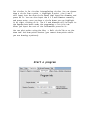
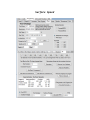
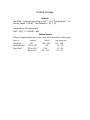
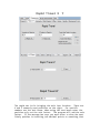
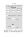
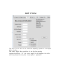
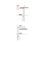
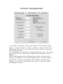
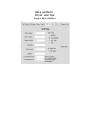
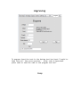
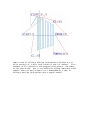
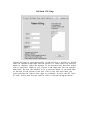
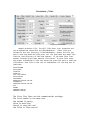
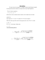
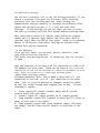
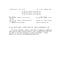
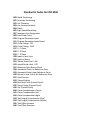
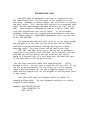
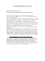
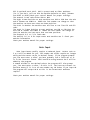
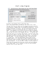
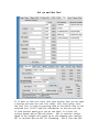
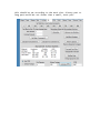
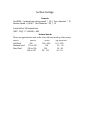
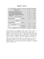
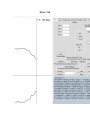
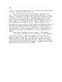
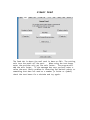
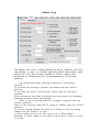
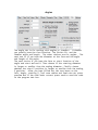
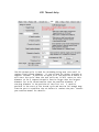
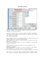
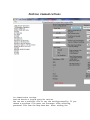
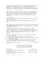
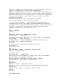
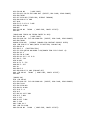
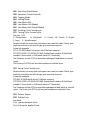
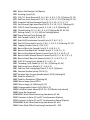
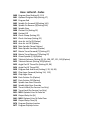
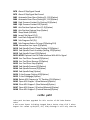
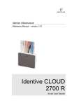
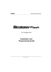
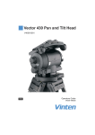
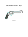
CNC Code Shooter Help
User Manual
Copyright 2009 - 2014 R. L. and V. L. Ellison
Table of Contents
Installation . . . . . . . . . . . . . . . . . . . . . . . . . . . . . . page 5
Mill
. . . . . . . . . . . . . . . . . . . . . . . . . . . . . . . . page 6
Starting a Program . . . . . . . . . . . . . . . . . . .
page 7-8
Set Up
. . . . . . . . . . . . . . . . . . . . . . . . page 9-10
Surface Speed . . . . . . . . . . . . . . . . . . . . . . . . . . . . . . . . page 11
Surface Footage . . . . . . . . .. . . . . . . . . . . . . . . . . . . . . page 12
Rapid
. . . . . . . . . . . . . . . . . . . . . . .
page 13-14
Feed
. . . . . . . . . . . . .. . . . .. . . . . ..
page 15
Bolt Circles . . . . . . . . . . . . . . . . . . . . . . .
page 16
Cutter Compensation . . . . . . . . . . . . . . . . .
page 17-19
Circular Interpolation . . . . . . . . . . . . . . . . . . . . . . .
page 20
Hole Patterns . . . . . . . . . . . . . . . . . . . . . . .
page 21-22
Engraving . . . . . . . . . . . . . . . . . . . . . . .
page 23-24
Pattern Milling . . . . . . . . . . . . . . . . . . . . . . .
page 25
Drawing patterns . . . . . . . . . . . . . . . . . . . . . . . page 26-28
Processor files
. . . . . . . . . . . . . . . . . . . . . . . page 29-31
Dxf files . . . . . . . . . . . . . . . . . . . . . . . . . . . . . . . . . . . . . . page 32
Sending a Tape file . . . . . . . . . . . . . . . . . . . . . .
page 32-36
Standard Mill G-Codes and M-Codes . . . . . . . . . . . . .
page37-39
Haas Mill G-Codes and M-Codes . . . . . . . . .. . . . . . . .
page 40-44
Mill Path . . . . . . . . . . . . . . . . . . . . . . .
page 45
Lathe
. . . . . . . . . . . . . . . . . . . . . . . . . page 46
Processor files . . . . . . . . . . . . . . . . . . . . . page 47-48
Starting a Program . . . . . . . . . . . . . . . . . . . page 49
Set Up and New Program . . . . . . . . . . . . . . . . . . . . . . . . page 50-51
Surface Footage . . . . . . . . . . . . . . . . . . . . . page 52
Rapid . . . . . . . . . . . . . . . . . . . . . . . . . . page 53
Draw . . . . . . . . . . . . . . . . . . . . . . . . . . page 54-56
Feed . . . . . . . . . . . . . . . . . . . . . . . . . . . page 57
Radius . . . . . . . . . . . . . . . . . . . . . . . . . page 58-59
Angles . . . . . . . . . . . . . . . . . . . . . . . . . . . page 60
Thread G76 . . . . . . . . . . . . . . . . . . . . . . . page 61
Thread G92 . . . . . . . . . . . . . . . . . . . . . . . page 62
Machine Communications. . . . . . . . . . . . . . . . page 63-68
Standard Lathe G-Codes and M-Codes . . . . . . . . . . . . . page 69-71
Haas Lathe G-Codes and M-Codes . . . . . . . . . . . . . . . . . page 72-76
Lathe Path . . . . . . . . . . . . . . . . . . . . . . . . page 77
Installation
1.
Requirements for Download:
You must have Microsoft Dot-Net Framework 2.0 or later to run this
program. The Dot-Net Framework comes standard with Vista and Windows 7.
You can download it from: http://msdn.microsoft.com/enus/netframework/default.aspx. has the .Net Framework 2.0
redistributable package that you need. Download it and install it onto
your hard drive. Follow the onscreen instructions to finish with the
install.
A monitor with a resolution of 768 x 1024 is required.
2.
Installation and Set - up:
After you have downloaded the program, now you are ready to
install it.
You have a file called: CNCCodeShooter3_** Install.exe. Double click
on that file to install the program on your hard drive.
Follow the
onscreen instructions to finish with the install. After installing you
must close down the program that starts from the installer. The program
will not function properly that starts from the installer. Start the
program from Start -> All programs. Sometimes you will have to right
click and choose run as administrator to get the program to run.
3. Now you can run the program, it should be in your program files,
CNCcodeShooter3_** folder.
Select all programs then select
CNCcodeShooter3_45 right click and click on Run as Administrator to
start the program.
CodeShooter now has two unique code generators. Instant and auto.
CNC CODE SHOOTER Instant - Help
To Open or Save a session, Look on the Start tab for Load Session and
Save Session. This will save the contents of the text boxes you have
filled out.
So if you don't have time to finish a program you can save your work or
if you need to make changes you can reload the session. The Tape file
(.t file) is saved separately under File->save or Save as or you can
open a saved one under File->Open.
CNC CODE SHOOTER Mill Auto - HELP
http://www.cnccodeshooter.com
http://www.cnccodeshooter.com/upload/CodeShooterPro.pdf
This Version will not open sessions from versions before
4.07 properly.
CNC Code Shooter is unique for creating CNC Gcode programs.
CNC Code Shooter is compiled to work on the latest Operating
Systems (XP, Vista,Windows7 and Windows8)
With this program you will be able to input your code then you
can send it to the text editor to view your whole program on
screen before you send it to the machine.
You will be able to
save your programs that you create so that next time you need to
run that particular part you will just have to pull up the code
make any changes that you may need to make, review it then send
it to the machine, just that easy. You will be able to print out
the code too. All of the features are fully functional on the
free trial version of this program.
A few basic precautions that you need to know when using and
running the program.
Always use good machining practices. Good visual care is
required to make sure that you are creating the correct tool path
for your program. Good visual care should be exercised when
inputting tool movements to make sure that all clamps and any
other fixtures clear the tool path.
Always remember to bring
your tools to clearance before continuing on to the next cut,
this is not an automatic program function so you need to make
sure you input the correct numbers as you build your programs.
The main difference with the pro is you can input patterns and
have the program figure the tool path. Go to draw tab section for more
information on drawing patterns.
Data Input
Data input boxes usually require a numbered input. Letters such as
Z or X will be added for you. Tool number and offset require an integer
while position moves can be in decimal format. If the program prompts
you,"You must enter a value" you have probably left a value out or it
is in the incorrect format. Z10.5 would be wrong because the Z will be
added by the program.
A common mistake is two decimal points the program will also prompt
you, "You must enter a value," as this is in the incorrect format. On
position moves if it is to an even number say 10 inches if you input 10
the program will output 10.0 as this is the format most machines
require.
Check your machine manual for proper settings.
The Draw Tab
The main difference with auto and instant codeshooter is
pro will compute tool path for you on profiles. The draw tab is
where you will draw your part. Begin by inputing your pattern
description and pressing the start pattern button. Then you input
either a line, angle or circular. Keep inputting dimensions until
the pattern is complete.
Mouse operation: Right click and drag across the drawiwng area to
rotate the axis, Press the scroll button then scroll to zoom in or out,
left click on a point or circle to highlight a point or circle.
Auto uses patterns (multiple lines and arcs in a continous line)
and points and circles to help you cut parts. Points and circles are
features and not part of patterns.
The Draw tab can be used for creating dimensional patterns.
You must input the lines or arcs in the order you want to machine
them. The best way to input radii is to draw your lines then
click on add radius click on two connecting lies when they are
highlighted input the radius value then the add adius button. The
advantages to doing it this way are you don't need to know the x
y center points and to change the radius juct click on the radius
and input the new value then press change radius.
As long as the path is continuous it should generate a
proper tool path however if say the fifth line intersects the
first it will not take in to account each other. The angles have
to be continuous. It only programs in the order they are drawn.
The end of one line or radius must be the beginning of the next
line or radius. Sometimes if you get a NAN it is because even
though the dimension lines intersect the tool path may not. The
program will automatically place the end of the current dimension
into the start X and Y for the next dimension. The draw tab make
the patterns. You can rotate the axis on the drawing screen by
right clicking and dragging across the drawing portion of the
screen.
You can change the viewing area and color under the view
tab when you close it down it saves current settings. If you use
metric it will save the settings so next time you don't have to
change them. if you have it set to 500 or 1000 and try to draw a
4 inch part it will be so small you won't be able to see it. Any
Z move above or below the minus or plus Z will not be visible.
So keep it in range of the Z view dimensions.
To actually generate a tool path: go to the Programming ->
Cut Patterns tab. You must have a tool selected with a tool
diameter for the program to generate a tool path. Choose the
pattern you wish to run. Choose whether to run just the pattern
or you can choose multiple't have tyo change.
Plus or minus is which side of the drawing the tool will
start on, You can right click on the plus or minus circles and it
will check the appropriate checkbox. On a horizontal line it
will start to the Y plus on a Vertical line it will start on the
X plus. If the first dimension is a circle minus is to the inside
of the circle plus is to the outside of the circle.
Multiple cuts is for when you want to take the pattern in
more than one cut. It will move down in Z run the pattern rapid
up rapid to the X and Y position move down rerun the pattern
until the desired depth is reached.
Also for more than one tool you can change tools then go
back to the dimensional tab and rerun the pattern.
You can
reset the G code and remake the G code for different tool sizes
or to cut on the opposite side.
You can edit the dimensional pattern on the draw tab by
selecting which line to edit in the draw tab drop down box then
press start edit. The reason for editing the patterns here is to
be able to redraw without changing tabs. After making your edits
press save edits then redraw.
You can also insert a line or
delete a line. Select the line to edit before pressing insert,
delete or start edit.
Remember the end of one line must be the
beginning of the next. All other edits are made from the Edit
tab.
As always if you find bugs please report them at:
[email protected].
The draw function gives CNC CodeShooter a powerful new
tool. First give your pattern a description then click -> start
pattern. To generate the proper tool path select whether you want
to start on the plus or minus of the dimension choose the feed
rate. Plus will start to the left side of the first angle or
line being greater than or equal to 45 degrees and less than or
equal to 270 degrees.
Minus will start on the right side of
angles less than 45 degrees and greater than 270. Draw your
pattern which can be a combination of lines angles and arcs.
Whether you want to draw a line which can also be an angled line
an angle or an arc. After filling out the relevant text boxes
press the draw button the information will be set and the
dimension drawn to the screen. You must draw it in the same
order you want to cut it and the first input point is the start
point. If you are going to go from a straight line to a radius
the tool paths must intersect or you will get NAN (not a number).
When you are finished be sure to press -> end pattern.
If you make a mistake on the plus or minus or tool diameter
you can press reset G- code make changes and press make code
button to generate new code. To make an edit select which line
number you want to edit and press the start edit button after
making changes press the save edit button. After saving changes
press redraw to see the modified figure. Remember the end of one
dimension must be the start of the next.
Cut circles is for circular interpolating circles. You can choose
draw a circle from a point -> highlight a point ; the X and Z
will input into the draw circle boxes then input the diameter and
press Do It. You can also input the X Y Z and Diameter manually
and press enter. once you have a circle drawn you can highlight
it by right clicking on it. The X Y and diameter will be input to
the appropriate boxes under the programing-> Cut cicle tab.
After you input the rest of the information press Do it.
You can plot points using the Misc -> Bolt circle Tab or on the
draw tab: the draw points buuton (you cannot draw points while
you are drawing a pattern).
Start a program
There are different ways to write a program. You can write
the whole thing from scratch or import frequently used tool lists
or you may have to rewrite an existing program to fix a problem
with it.
To save time frequently used tools can be saved to a tool list
then the session is saved say as toollist1 or something.
To Open or Save a session, Look on the Start tab for Load Session
and Save Session. This will save the contents of the text boxes
you have filled out.
To start a program either open the tool list you need or
input the tools you will use on the set up tab. Then choose a
program number and input it under the Program tab. The program
number can be input at anytime it doesn't have to be first but
before you make the program you have to input a program number.
Program comments are optional. If you are going to mill
something and have the tool path figured for you use the draw
tab to draw or edit the drawing.
Before you run the first tool you can send the tool
information from the setup tab to the tool tab by pressing the
send button next to the tool you are going to use on the set up
page. Make sure the machine is in a position where the tool
changer will clear everything before it changes tools.
After
each operation you can send each axis home before you change to
the next tool. You can change the home position for a machine in
the processor tab. You can have multiple processor files for
each machine with different home positions as some fixtures might
require a special home position.
After all machining programming is done you can view the
tool path under the code tab. But before you can make code you
have to choose a machine processor file. The mill path line is
the center of the tool path so a large diameter tool will have a
tool path that is farther from the dimensional lines than a
narrow tool.
Bolt pattern holes will show the relative hole
size if you have input the tool diameter +(TOOL DIAM = 2.00) for
example. Otherwise mill path will show a one inch tool or the
last read tool. Future versions will show the tool width for
milling operations but for now show the tool center line.
If you don't have time to finish a program you can save
your work or if you need to make changes you can reload the
session. The Tape file (.t file) is saved separately under File>save or Save as or you can open a saved one under File->Open.
To start a new program click on the Program tab.
Enter the program number the program will add the Letter O.
The next text box is for program description and Set up
information. Comments must be enclosed by parenthesis. If you
choose a processor file with a yes on $ and percent those will
be added. If not or you choose one that is no they will not be
added. This depends on the control you are writing the program
for. Click make code to preview the code if it looks right press
send to send the code to the program text box. To load the text
boxes with data you can choose load session. This will place data
that you have saved in the data input text boxes. If you have to
save data press the save session button and data in text boxes
will be saved.
To save a program go file-> save and save as
a .T(tape) file. Save and load session always opens the my
document folder it is a good idea to make a Lathe session and
mill session folder and lathe programs and mill program folder in
your my documents. Or you can make a folder for each program in
lathe and mill programs and save your session and tape programs
in the same folder. This is helpful if you will have multiple
session files for each tape file.
Set Up
It is best to save tool lists with save session then you can open
a session and have the tool list ready with less typing. Once the
tool list is ready by pressing send on the button next to the
selected tool it will send the information to the Offset tab. To
find spindle speed go to the #s tab their is a chart for surface
speeds and an RPM calculator.
You can also print the whole page for a setup sheet by
pressing send page at the bottom of the tab it will send the page
to the Tape box so it can be printed. Remove it before sending
the program to the Machine as this is not part of the program.
Surface Speed
Surface Footage
Formula
Tool RPM = (surface foot cutting speed * 12) / Tool diameter * PI
Surface Speed = ( RPM * Tool Diameter * PI) / 12
1 inch drill at 100 surface feet
(100 * 12)/( 1 * 3.14159) = 382
Surface Speeds
These are approximate start on the slow side and work up if necessary.
Material
Soft Steel
Medium Steel
Hard Steel
Hardness
100
175 to 220
220 to 300
300 to 425
Carbide
500 - 900
350
250
80 - 130
High Speed Steel
110 - 200
70 - 110
30 - 80
20 - 50
Rapid Travel X
Y
The rapid tab is for bringing the axis into location. There are
X and Z commonly used positions on the right. For specific
numbers use the text boxes. When using the text boxes enter the
position only not the axis letter. The program will add the axis
letter. If the message box says you must enter a value the most
likely problem is inserting two decimal points or something that
does not read as a number (a letter or symbol) check the text
boxes for a mistake and try again. The coolant on is most often
used when bringing the tool up to the part usually when the
machine rapids to 1 inch off the face turn coolant on. When the
machine rapids an inch off the part and the operation is finished
turn the coolant off.
Feed X Y
The feed tab is where the real work is done on CNCs. The cutting
axis turn the metal off the part.
When using the text boxes
enter the position only not the axis letter. The program will
add the axis letter. If the message box says you must enter a
value the most likely problem is inserting two decimal points or
something that does not read as a number (a letter or symbol)
check the text boxes for a mistake and try again.
Bolt Circle
The bolt Circle tab can be used for equally spaced or non equal
bolt circles.
The start angle Zero position is at X plus moving
counterclockwise. If the start angle is 45 degrees the hole
will be placed in the plus X and plus Y quadrant.
Cutter Compensation
Cutter compensation is very useful for precision milling.
You can program a tool path without it but if it doesn't cut to
the required size you would have to reprogram.
Compensation allows you to compensate for different size
tools or tool pressure. Using cutter compensation will result in
a tool path equivalent to the part dimensions.
G41 is for left
cutter comp G42 is for right cutter comp. G40 is for no cutter
comp.
The offset values are stored as either D or H offset
values. If the control uses H it has to be a different number
than the length offset number. It is best to use a one axis move
to bring the cutter into position never use an arc move to
position the tool. The move right after the position move has to
be coordinated with the cutter comp (left for G41 right for G42).
While the comp is on all blocks should contain an axis move( No
blocks with just an M08 for example).
***If you use the wrong comp (G41 or G42) the tool will
position to the wrong side of the tool. It is a good idea to
offset the tool up before running the cut to make sure there are
no errors.
Circular Interpolation
To circular interpolate a part you have a choice between Input
angles, X large X small, Y large, Y small on start position and
finish position so you can cut a full circle use the same start
and finish position.
Or in 90 degree increments by choosing different start and finish
point also you can choose input angle and interpolate various
degrees.
After choosing direction clockwise and counter clockwise and
inside or outside of the circle diameter input the text boxes X
center and Y center Tool diameter Part Radius and feed press
preview. If the code looks good press send to send the code to
the program text box.
Hole pattern
Drill and Tap
Single Hole Pattern
Multiple Hole Pattern
Drill and tap can be used for a single hole as in the upper picture or
a pattern as in the lower picture.
Engraving
To engrave input the text in the bottom text box input Z rapid to
feed rate etc. then press preview . After code is generated
press send to send the code to the program text box.
Ramp
Ramp is used for milling a back and forth pattern from Start X,Y to
X2,Y2 moving in X, Y and Z until Finish X,Y and Z is reached.
If no
movement in Z is required it will program a flat pattern. The number
of cuts must be odd. This is very useful for milling ramps with a ball
endmill, where you may increment 2 to 5 thousandths at a time, or
milling a back and forth pattern with a regular endmill.
Pattern Milling
Pattern milling is used extensively in CNC Milling. A pattern is milled
then the spindle drops down and the pattern is recut until the desired
depth is reached. Input the pattern in the pattern text box then select
start Z position, depth of cut, Finish Z and Feed rate for the spindle
down move. Be sure the spindle is in a position where it can feed down
at the end of the pattern.(the last line in the text box) When you
press preview the code on the right is produced. In this case 87 lines
of code. Press send and the code is sent to the main program editor.
Processor files
Sample processor file. The mill files have a psr extension and
can be opened and saved with the CNCCodeShooter. These files are
located in the root directory of CNCCodeShooter. Choose the file you
want in the drop down box then press set. The drop down box reads file
from the root directory of CNC Code Shooter. If you need files from
another location press open machine file button. To save files enter
the proper information in the text boxes and press the Save or make new
file button. Save file in the root of Codeshooter for the drop box to
read them.
baudrate4800
parityEVEN
stopbits1
databits7
flow controlNone
workshiftG54
EndcodeM30
XHomepositionG91 G28 X0.
hasG98ynYes
ZHomepositionG91 G28 Z0.
EorF
HasWNo
YHomeG91 G28 Y0.
wHomeG91 G28 W0.
The first five lines are the communication settings.
The first number is the baud rate
the second is parity,
third is data bits,
fourth is stop bits and
the fifth is flow control.
The sixth is work shift depending on the machine. Example work
shift would be G54 for most controls.
G55 is optional work shift. G92 is preset used on older machines.
(ie. if you don't call out G54 the machine defaults to G50).
(Okumas use G15P1 or G15P?)Check your control Manuel for proper
settings.
The seventh is end code either M30 or M02.
The eight X Home Position on most machines use G28 or G30 then
the axis and 0. Okumas use G30P1 or G30P2 the last number can
change so that the machine can have more than one home position.
The ninth is drill code some machines require a G98 for return
level.(For Okumas leave this empty).If the drill code requires
G98 input Yes if it is null(ie it doesn't use G98) make it No.
The tenth is Z Home Position on most machines use G28 or G30 then
the axis and 0. Okumas use G30P1 or G30P2 the last number can
change so that the machine can have more than one home position.
The eleventh is E or F for feed code.
The twelfth is has W if the machine has a W axis.
The thirteenth is Y Home Position on most machines use G28 or G30
then the axis and
0. Okumas use G30P1 or G30P2 the last number can change so that
the machine can have more than one home position.
The fourteenth is W Home Position on most machines use G28 or G30
then the axis and 0. Okumas use G30P1 or G30P2 the last number
can change so that the machine can have more than one home
position.
The fifteenth is offset length code usually G43 Okuma controls
use G56
Check your machine manual for proper settings.
Dxf Files
Version 3.7.2 is the first version to open and save Dxf files. It
is currently limited to lines and arcs. You can use AutoCAD or
Libre Cad to draw or view prints. If you open a Dxf file in
CodeShooter it will list the lines first then the Arcs. The
first line or Arc has to have the proper start and end points. It
has to be drawn in the same way you want to cut. All Dxf files
arcs are counter clockwise so if you start with an arc it should
be counter clockwise. If you start with a line it will match an
arc start points to the line end points.
NetDxf is a Dxf reader writer library we are using now.
The following copyright notice applies only to NetDxf:
Copyright (C) 2012 Daniel Carvajal ([email protected])
This library is free software; you can redistribute it and/or
modify it under the terms of the GNU Lesser General Public
License as published by the Free Software Foundation; either
version 2.1 of the License, or (at your option) any later version.
The above copyright notice and this permission notice shall be
included in all copies or substantial portions of the Software.
THE SOFTWARE IS PROVIDED "AS IS", WITHOUT WARRANTY OF ANY KIND,
EXPRESS OR
IMPLIED, INCLUDING BUT NOT LIMITED TO THE WARRANTIES OF
MERCHANTABILITY, FITNESS
FOR A PARTICULAR PURPOSE AND NONINFRINGEMENT. IN NO EVENT SHALL THE
AUTHORS OR
COPYRIGHT HOLDERS BE LIABLE FOR ANY CLAIM, DAMAGES OR OTHER LIABILITY,
WHETHER
IN AN ACTION OF CONTRACT, TORT OR OTHERWISE, ARISING FROM, OUT OF OR
IN
CONNECTION WITH THE SOFTWARE OR THE USE OR OTHER DEALINGS IN THE
SOFTWARE.
You can find more information at:
http://netdxf.codeplex.com/
Geometry
The main reason this program is so helpful is the fact that finding the straight
line tool path intersection with an arc requires the use of complex equations.
The circle whose equation is
(x - x0)2 + (y - y0)2 = r 2
Where X0 is the X center coordinate and where Y0 is the Y center coordinate and r is the radius.
and the line
slope equals (Y2 - Y1) / (X2 - X1) where X2 - X1 does not equal 0.
Where M is the slope and b is the Y intercept point (the value of Y at X = 0) then.
y = mx + b
if X2 - X1 = 0 the slope is infinity then
y=x+b
have intersection points at
Send and Receive
Using the send tab
For Communication settings.
You can use a processor file or set the settings manually. If you
choose a processor file press use Processor after selecting
processor file from the drop down box. After setting the
communication settings manually or choosing the processor files
choose the com port(com port 1, 2, 3 etc) and press Save
Settings. If the settings are not set right you have to close
the port by pressing the Close Port button before resetting them.
Most Controllers require a $ (dollar sign) before the program
number and a % (percent sign) before the first block and a %
(percent sign) after the M30 or last block. Refer to the machine
manual to verify each controllers settings on the particular
machine that you are operating.
To set manually
First you will select the com port, parity, data bits, baud
rate,flow control and stop bits.
Then press save settings button. It should say that the com port
is open.
Most new computers do not have a RS 232 connection so a USB to RS
232 adapter has to be used. These can be found at Fry's, Most new
computers do not have a RS 232 connection so a USB to RS 232 adapter has to be
used. These can be found at Fry's Radio Shack and other places.
Radio Shack and other places.
Software Handshake Cable - How to make a cable with a 9 - pin
connection on one side to a 25 - pin connection on the other
side. This is a typical machine to computer connection cable.
We sell the cables already made ranging from 20 feet - 50 feet,
shielded or regular.
1. Cross signals SD (serial transmit data) and RD (serial
receive data) with each other.
2. Connect signal SG( signal ground) to SG (signal ground).
3. Jump together signals RTS (request to send) and CTS (clear to
send) at both ends of the cable.
4. Jump together signals DTR (data terminal ready), DSR (data
set ready), and DCD (data carrier detect) at both ends of the
cable.
Machine Side
DB - 25 pin
DB - 9 pin
Computer Side
SD (pin #2) connect to RD (pin #2)
RD (pin #3) connect to SD (pin #3)
SG (pin #7) connect to SG (pin #5)
DB RTS
(pin
DSR
(pin
25 pin
(pin #4) jumper to CTS (pin #5)
#8)
(pin #6) jumper to DCD (pin #8) and
#4) and
jumper to DTR (pin #20)
DB - 9 pin
RTS (pin #7) jumper to CTS
DCD (pin #1)
jumper to DTR
jumper to DSR (pin #6)
Or you could order a cable online at: www.cnccodeshooter.com.
If you do encounter a bug or just have a suggestion something
that you may need, please e-mail us your request and we will do
our best to fix the situation as soon as possible. E-Mail
address is: mail to:[email protected].
Below is a snapshot of a program created by CNC Code Shooter
Mill. You will be able to create a program from beginning to the
end with CNCCodeShooter.
Begin your program with the start tab, setting your program
number, the tool description, and the work shift. Next you will
click the button Make Code and preview it in the preview box. If
the code is good then click the send button to send it over to
the text editor to start creating your program.
Renumber your program to your own sequence of numbers
for your own program or use the default setting.
This is just an example . Every machine will have different
configurations and will be slightly different depending on
specific settings that are required by different machines. Refer
to the machine manual for the specific settings required by
individual machines.(example: the baud rate, or the parity, etc.)
$
:00001 Flange Adapter (Program Description)
(More Description)
%
#4 CENTER DRILL (Tool Description)
N1 G90 G80 G40 G00 G17 (Cancel Codes)
N2 S1000 M03 (spindle 1000rpm / forward)
G15P1 (Work shift)
N3 G00 X2.1213 Y2.1213 (1st position move)
N4 G56 Z1.0 H1 M08
(work shift)
N5 G81 Z-.28 R.1 F2.0 M54 (drill Cycle)
N6 Z-2.1213
N7 Y-2.1213
N8 X2.1213
N9 X3.2476 Y1.875
N10 X0 Y-3.75
N11 X-3.2476 Y1.875
N12 Y-1.875
N13 X0 Y-3.75
N14 X3.2476 Y-1.875
N15 G80 G00 Z1.0
N16 G91 G30P1 Z0 M09
N17 G90 M01
N18 T2 M06
(17/32 DIA. DRILL)
N28 G90 G80 G40 G00 G17
N29 S539 M03
N30 G00 X2.1213 Y2.1213
N31 G56 Z1.0 H2 M08
N32 G83 Z-.9596 R.1 Q.1 F4.3
N33 X-2.1213
N34 Y-2.1213
N35 X2.1213
N36 G80 G00 Z1.0
N37 G91 G30P1 Z0 M09
N38 G90 M01
N39 T3 M06
(27/64 DIA. DRILL)
N49 G90 G80 G40 G00 G17
N50 S679 M03
N51 G00 X3.2476 Y1.875
N52 G56 Z1.0 H3 M08
N53 G83 Z-.9268 R.1 Q.1 F5.0
N54 X0 Y3.75
N55 X-3.2476 Y1.875
N56 Y-1.875
N57 X3.2476 Y-1.875
N58 G80 G00 Z1.0
N59 G91 G30P1 Z0 M09
N60 G90 M01
N61 T1 M06
N62 M30
%
A word about rapid travel.
Rapid travel does not always rapid point to point.
Most Fanuc machines rapid at a forty five degree angle until one axis
reaches it's destination then the other axis travels in a straight line until it
reaches it's destination.
As always be careful running a CNC machine.
Standard G Codes for CNC Mills
G00
G01
G02
G03
G04
G05
G07
G09
G10
G11
G12
G13
G17
G18
G19
G20
G21
G22
G23
G27
G28
G29
G30
G31
G33
G34
G35
G36
G40
G41
G42
G43
G44
G45
G46
Rapid Positioning
Feed rate Positioning
Arc Clockwise
Arc Counterclockwise
Dwell
High Speed Machining
Imaginary Axis Designation
Exact Stop Check
Program Parameter Input
Program Parameter Input Cancel
Circle Cutting CW
Circle Cutting CCW
X - Y Plane
X - Z Plane
Y - Z Plane
Input in Inch Units
Input in Metric
Stored Stroke Limit ON
stored Stroke Limit OFF
Reference Point Return Check
Automatic Return to Reference Point
Automatic Return from Reference Point
Return to 2nd, 3rd or 4th Reference Point
Skip Function
Thread Cutting
Bolt Hole Circle (Canned Cycle)
Line at Angle (Canned Cycle)
Arc (Canned Cycle)
Cutter Compensation Cancel
Cutter Compensation Left
Cutter Compensation Right
Tool Length Compensation (Plus)
Tool Length Compensation (Minus)
Tool Offset Increase
Tool Offset Decrease
G49 Tool Length Compensation Cancel
G50 Scaling OFF
G51 Scaling ON
G52 Local Coordinate Setting
G53 Machine Coordinate Setting
G54 Work piece Coordinate #1
G55 Work piece Coordinate #2
G56 Work piece Coordinate #3
G57 Work piece Coordinate #4
G58 Work piece Coordinate #5
G59 Work piece Coordinate #6
G60 Single Direction Positioning
G62 Automatic Corner Override
G63 Tapping Mode
G64 Cutting Mode
G65 Custom Macro -Simple
G66 Custom Macro -Modal
G67 Custom Macro Cancel-Modal
G68 Coordinate System Rotation-ON
G69 Coordinate System Rotation-OFF
G70 Input in Inch Units
G71 Input in Metric Units
G73 High Speed Peck Drilling Cycle
G74 Left Hand Tapping Cycle
G76 Fine Boring Cycle
G80 Canned Cycle Cancel
G81 Drilling Cycle - Canned Cycle
G82 Counter Boring Cycle - Canned Cycle
G83 Peck Drilling Cycle - Canned Cycle
G84 Right Hand Tapping Cycle - Canned Cycle
G85 Boring Cycle - Canned Cycle
G87 Back Boring Cycle - Canned Cycle
G90 Absolute Positioning
Movement in relation to a fixed point (ie X0 Y0)
G91 Incremental Positioning
movement from current position
G91 X1.01 would move 1.01 in X axis from wherever the machine currently
is
G92
G94
G95
G96
G97
G98
G99
Reposition Origin Point
Feed Per Minute
Feed Per Revolution
Constant Surface Speed
Constant Surface Speed Cancel
Set Initial Plane (Default)
Return to Rapid Plane
Standard Used "M" Codes for Mills
M00
M01
M02
M03
M04
M05
M06
M07
M08
M09
M10
M11
M12
M14
M15
M16
M18
M19
M29
M30
M60
M61
M62
M98
M99
Program Stop
Optional Stop
Program End
Spindle Clockwise
Spindle Counter Clockwise
Spindle Stop
Tool Change
Thru Spindle Coolant ON
Flood Coolant ON
Coolant Off (all coolant)
Table Pallet Clamp
Table Pallet Unclamp
Shower Coolant On
Spindle Air Blow On
Spindle Air Blow Off
Air Blast / Tool Changer
Air Blast Off
Spindle Orientation
Rigid Tapping Lock Feed to RPM
End Program
Pallet Change
Load Pallet #1
Load Pallet #2
Sub Program Start
Sub Program Cancel
Haas Mill G-Codes G00 Thru G187
G00* Rapid Positioning Motion (X, Y, Z, A, B)(Setting 10, 56, 101)
G01 Linear Interpolation Motion (X, Y, Z, A, B, F) (Setting 85)
G02 Circular Interpolation Motion CW (X, Y, Z, A, I, J, K, R, F)
G03 Circular Interpolation Motion CCW (X, Y, Z, A, I, J, K, R, F)
G04 Dwell(P)(P=Seconds*.*Milliseconds)
G09 Exact Stop, Non-Modal
G10 Programmable Offset Setting (X, Y, Z, A, L, P, R)
G12 CW Circular Pocket Milling (Z, I, K, Q, D, L, F)
G13 CCW Circular Pocket Milling (Z, I, K, Q, D, L, F)
G17* Circular Motion XY Plane Selection (G02 or G03)(Setting 56)
G18 Circular Motion ZX Plane Selection (G02 or G03)
G19 Circular Motion YZ Plane Selection (G02 or G03)
G20* Verify Inch Coordinate Positioning (Setting 9=Inch)
G21 Verify Metric Coordinate Positioning (Setting 9=MM)
G28 Machine Zero Return thru Ref. Point (X, Y, Z, A, B)(Setting 108)
G29 Move to Location Through G28 Ref. Point (X, Y, Z, A, B)
G31 Feed Until Skip Function (X, Y, Z, A, B, F)(Option)
G35 Automatic Tool Diameter Measurement (D, H, Z, F)(Option)
G36 Automatic Work Offset Measurement (X, Y, Z, A, B, I, J, K, F)(Option)
G37 Automatic Tool Length Measurement (D, H, Z, F)(Option)
G40* Cutter Comp Cancel G41/G42/G141 (X, Y)
G41 2D Cutter Compensation, Left (X, Y, D)(Setting 40, 43, 44, 58)
G42 2D Cutter Compensation, Right (X,Y,D)(Setting 40, 43, 44, 58)
G43 Tool Length Compensation+ (H, Z)(Setting 15)
G44 Tool Length Compensation- (H, Z)(Setting 15)
G47 Text Engraving (X, Y, Z, R, I, J, P, E, F)(Macro Var. 599 for Serial #)
G49* Tool Length Compensation Cancel G43/G44/G143 (Setting 56)
G50 Scaling G51 Cancel (Setting 56)
G51 Scaling (X, Y, Z, P)(Setting 71)(Option)
G52 Work Offset Positioning Coordinate (Setting 33=Yasnac)
G52 Global Work Coordinate Offset Shift (Setting 33=Fanuc)
G52 Global Work Coordinate Offset Shift (Setting 33=Haas)
G53 Machine Positioning Coordinate, Non-Modal (X, Y, Z, A, B)
G54* Work Offset Positioning Coordinate #1 (Setting 56)
G55 Work Offset Positioning Coordinate #2
G56 Work Offset Positioning Coordinate #3
G57 Work Offset Positioning Coordinate #4
G58 Work Offset Positioning Coordinate #5
G59 Work Offset Positioning Coordinate #6
G60 Uni-Directional Positioning (X, Y, Z, A, B)(Setting 35)
G61 Exact Stop, Modal (X, Y, Z, A, B)
G64* Exact Stop G61 Cancel (Setting 56)
G65 Macro Sub-Routine Call (Option)
G68 Rotation (G17, G18, G19, X, Y, Z, R)(Setting 72, 73)(Option)
G69* Rotation G68 Cancel (Setting 56)
G70 Bolt Hole Circle with a Canned Cycle (I, J, K, L)
G71 Bolt Hole Arc with a Canned Cycle (I, J, K, L)
G72 Bolt Holes along an Angle with a Canned Cycle (I, J, L)
G73 HS Peck Drilling Canned Cycle (X, Y, A, B, Z, I, J, K, Q, P, R, L, F)(Setting
22, 52)
G74 Reverse Tapping Canned Cycle (X, Y, A, B, Z, J, R, L, F)(Setting 130)
G76 Fine Boring Canned Cycle (X, Y, A, B, Z, I, J, P, Q, R, L, F)(Setting 27)
G77 Back Bore Canned Cycle (X, Y, A, B, Z, I, J, Q, R, L, F)(Setting 27)
G80* Cancel Canned Cycle (Setting 56)
G81 Drill Canned Cycle (X, Y, A, B, Z, R, L, F)
G82 Spot Drill/Counterbore Canned Cycle (X, Y, A, B, Z, P, R, L, F)
G83 Peck Drill Deep Hole Canned Cycle (X, Y, A, B, Z, I, J, K, Q, P, R, L, F)(Set.
22,52)
G84 Tapping Canned Cycle (X, Y, A, B, Z, J, R, L, F)(Setting 130)
G85 Bore In-Bore Out Canned Cycle (X, Y, A, B, Z, R, L, F)
G86 Bore In-Stop-Rapid Out Canned Cycle (X, Y, A, B, Z, R, L, F)
G87 Bore In-Manual Retract Canned Cycle (X, Y, A, B, Z, R, L, F)
G88 Bore In-Dwell-Manual Retract Canned Cycle (X, Y, A, B, Z, P, R, L, F)
G89 Bore In-Dwell-Bore Out Canned Cycle (X, Y, A, B, Z, P, R, L, F)
G90* Absolute Positioning Command
G91 Incremental Positioning Command (Setting 29)
G92 Global Work Coordinate System(Fanuc)(Haas)(Setting 33)
G92 Set Work Coordinate Value (Yasnac)(Setting 33)
G93 Inverse Time Feed Mode On
G94* Inverse Time Feed Off/Feed Per Minute On (Setting 56)
G95 Feed Per Revolution
G98* Canned Cycle Initial Point Return (Setting 56)
G99 Canned Cycle R Plane Return
G100 Mirror Image G101 Cancel (X, Y, Z, A, B)
G101 Mirror Image (X, Y, Z, A, B)(Setting 45, 46, 47, 48, 80)
G102 Programmable Output to RS-232 (X, Y, Z, A, B)
G103 Limit Block Look-ahead (PO-P15=# of Blocks Look-ahead)
G107 Cylindrical Mapping (X, Y, Z, A, Q, R)
G110-G129 Work Offset Positioning Coordinate #7-26
G136 Automatic Work Offset Center Measurement (Option)
G141 3D Cutter Compensation (X, Y, Z, I, J, K, D, F)
G150 General Pocket Milling Routine (X, Y, P, Z, I, J, K, Q, D, R, L, S, F)
G154 Select Work Offset Positioning Coordinate P1-P99
G174 Special Non-Vertical Rigid Tapping CCW (X, Y, Z, F)
G184 Special Non-Vertical Rigid Tapping CW (X, Y, Z, F)
G187 Default Smoothness (E)(Setting 85)
G188 Pallet Schedule Table Status Check (PST)
5 Axis G-Codes (Optioal)
G143 5-Axis Tool Length Comp.+ (X, Y, Z, A, B, H)(Set. 15, 117)
G153 5-Axis HSP Drill (X, Y, A, B, Z, I, J, K, Q, P, E, L, F)(Setting 22)
G155 5-Axis Reverse Tapping Canned Cycle (X, Y, A, B, Z, J, E, L, F)
G161 5-Axis Drill Canned Cycle (X, Y, A, B, Z, E, L, F)
G162 5-Axis Spot Drill/C-Bore Canned Cycle (X, Y, A, B, Z, P, E, L, F)
G163 5-Axis Peck Drill Canned Cycle (X, Y, A, B, Z, I, J, K, Q, P, E, L, F)(Setting
22)
G164 5-Axis Tapping Canned Cycle (X, Y, A, B, Z, J, E, L, F))
G165 5-Axis Bore In, Bore Out Canned Cycle (X, Y, A, B, Z, E, L, F)
G166 5-Axis Bore In, Stop, Rapid Out Canned Cycle (X, Y, A, B, Z, E, L, F)
G169 5-Axis Bore In, Dwell, Bore Out Canned Cycle (X, Y, A, B, Z, P, E, L, F)
* Default
Haas Mill M-Codes M00 - M109
M00 Program Stop (Setting 42)
M01 Optional Program Stop (Setting 17)
M02 Program End
M03 Spindle On Clockwise (S)(Setting 144)
M04 Spindle On Counterclockwise (S)(Setting 144)
M05 Spindle Stop
M06 Tool Change(T)(Setting 42, 87, 90, 155)
M08 Coolant On (Setting 32)
M09 Coolant Off
M10 4th Axis Brake On (Option)
M11 4th Axis Brake Release (Option)
M12 5th Axis Brake On (Option)
M13 5th Axis Brake Release (Option)
M16 Tool Change (T)(Setting 42, 87, 90, 155)
M17 Unclamp APC Pallet and Open APC Door
M18 Clamp APC Pallet and Close APC Door
M19 Orient Spindle (P and R are Optional)
M21-M28 Optional User M Code Interface with M-Fin Signal
M30 Program End and Reset (Setting 2, 39, 56, 83)
M31 Chip Auger Forward (Setting 114, 115)
M33 Chip Auger Stop
M34 Coolant Spigot Position Down, Increment
M35 Coolant Spigot Position Up, Decrement
M36 Pallet Part Ready (Option)
M39 Rotate Tool Carusel (T)(Setting 86)
M41 Spindle Low Gear Override
M42 Spindle High Gear Override
M50 Execute Pallet Change (Setting 121 Thru 129)(Option)
M51-M58 Optional User M Code Set
M59 Output Relay Clear Set (N)
M61-M68 Optional User M Code Clear
M69 Output Relay Clear (N)
M75 Set G35 or G136 Reference Point
M76 Control Display Inactive
M77 Control Display Active
M78 Alarm If Skip Signal Found
M79 Alarm If Skip Signal Not Found
M80 Automatic Door Open (Setting 131)(Option)
M81 Automatic Door Close (Setting 131)(Option)
M82 Tool Unclamp
M83 Auto Air Jet On (Option)
M84 Auto Air Jet Off (Option)
M86 Tool Clamp
M88 Coolant Through Spindle On (Setting 32)(Option)
M89 Coolant Through Spindle Off (Option)
M93 Axis Pos Capture Start (P,Q)
M94 Axis Pos Capture Stop
M95 Sleep Mode
M96 Jump If No Signal (P,Q)
M97 Local Sub-Program Call (P,L)
M98 Sub-Program Call (P,L)
M99 Sub-Program Return or Loop (P)(Setting 118)
M109 Interactive User Input (P)(Option)
CNC MILL PATH - HELP
CNC Mill Path is designed to be used in conjunction with
CNC Code Shooter Mill. The tool path is the centerline of the
tool path. Remember on square corners you still have to consider
the tool radius. This version will not work in incremental mode
(G91). We have approximated the home positions for (G91, G28 or
G30)
This program is designed to stop on a M30 or a M02, make
sure your program ends with one of these.
If you encounter
problems, please send your program and an explanation with what
it is doing wrong to: [email protected] or you can call
us at: 936 588-7561.
The program has zoom and shift so if it is not large enough
you can zoom in or out also you can shift the view off X0 Y0.
Zoom has to be pressed before running the program or after
pressing reset. The timer slider can be used at any time.
G81, G83, and G84, drill, peck, and tap are in different
colors so if you center drill with G81. drill with G83, and tap
with G84 you will be able to see the different tool paths.
Rapid is a hatched line, if a tool goes over the same tool path
in the same mode it will be hard to see.
You can input workshift under Edit Show WorkShift.
G54 is
assumed to be 0. You can input a value for G55 thru G59. If you
run two or more workshifts (ie two vises) you can for example
input a positive number for one and a negative number for the
other and the program will run the program in two differant parts
of the screen.
Mill path will read Tool diameter which is useful for
showing drilled holes. The tool diameter should be on a block
without a block number.
example: N10 G40 G50 G90 G17
(TOOL DIAMETER=.75)
N20 G43 H1
CNC CODE SHOOTER LATHE - HELP
http://www.cnccodeshooter.com
http://www.cnccodeshooter.com/upload/CodeShooterPro.pdf
CNC Code Shooter is unique for creating CNC G-code programs.
CNC Code Shooter is compiled to work on the latest Operating Systems
(XP, Vista and Windows 7)
With this program you will be able to input your code then you can send
it to the text editor to view your whole program on the computer screen
before you send it to the machine.
You will be able to save your
programs that you create so that next time you need to run that
particular part you will just have to pull up the code make any changes
that you may need to make, review it then send it to the machine, just
that easy. You will be able to print out the code too. Some of the
features are disabled on the free version of this program.
A few basic precautions that you need to know when using and running
the program.
Always use good machining practices. Good visual care is required to
make sure that you are creating the correct tool path for your program.
Good visual care should be exercised when inputting tool movements to
make sure that all clamps and any other fixtures clear the tool path.
Always remember to bring your tools to clearance before continuing on
to the next cut, this is not an automatic program function so you need
to make sure you input the correct numbers as you build your programs.
Tool simulation is new as of version 3.8.
The program will show some tools : To show tools, input at the tool
description: (LH TNMG M04),(LH TNMG),(RH CNMG),(RH CNMG M04),(RH DNMG),
(RH DNMG M04),(RH TNMG),(RH TNMG M04)(RH VNMG),(RH VNMG M04),(OD
THREADING TOOL),(ID THREADING TOOL),(FACE GROOVE TOOL),(OD GROOVE
TOOL),(OD GROOVE TOOL),(BACK FACE GROOVE TOOL) or (LH BAR TNMG) these
are the only tools accepted they must be in Caps. M4 or M04 will show
the reverse of the tool as if it were upside down.
Processor files
Sample processor file. The lathe files have a lsr extension and can be
opened and saved with the CNCCodeShooter. These files are located in
the root directory of CNCCodeShooter. Choose the file you want in the
drop down box then press set. The drop down box reads file from the
root directory of CNC Code Shooter. If you need files from another
location press open machine file button. To save files enter the proper
information in the text boxes and press the Save or make new file
button. Save file in the root of Codeshooter for the drop box to read
them.
baudrate4800
parityEVEN
stopbits1
databits7
flow controlNone
workshiftG54
EndcodeM30
XHomepositionX15.
oneortwo2
ZHomepositionZ10.
EorF
IorR
The first five lines are the communication settings.
The first number is the baud rate
the second is parity,
third is data bits,
fourth is stop bits and
the fifth is flow control.
The sixth is work shift depending on the machine. Example work shift
would be G54 for most controls.
G55 is optional work shift. G92 is preset used on older machines.
(ie. if you don't call out G54 the machine defaults to G50). (Okumas
use G15P1 or G15P?)Check your control Manuel for proper settings.
The seventh is end code either M30 or M02.
The eight X Home Position on most machines use G28 or G30 then the axis
and 0. Okumas use G30P1 or G30P2 the last number can change so that
the machine can have more than one home position.
The ninth is whether the machine uses one line or two line G71 and G72
code.
The tenth is Z Home Position on most machines use G28 or G30 then the
axis and 0. Okumas use G30P1 or G30P2 the last number can change so
that the machine can have more than one home position.
The eleventh is E or F for feed code.
The twelfth is I or R for taper moves most machine use I. Check your
machine information
Check your machine manual for proper settings.
Data Input
Data input boxes usually require a numbered input. Letters such as
Z or X will be added for you. Tool number and offset require an integer
while position moves can be in decimal format. If the program prompts
you,"You must enter a value" you have probably left a value out or it
is in the incorrect format. Z10.5 would be wrong because the Z will be
added by the program.
A common mistake is two decimal points the program will also prompt
you, "You must enter a value," as this is in the incorrect format. On
position moves if it is to an even number say 10 inches if you input 10
the program will output 10.0 as this is the format most machines
require.
Check your machine manual for proper settings.
Start a New Program
To start a new program click on the start tab.
Enter the program number preceded by the Letter O not a zero.
The next Text two text boxes are for program description and Set
up information. Comments must be enclosed by parenthesis. If you
choose a processor file with a yes on $ and percent those will
be added. If not or you choose one that is no they will not be
added. This depends on the control you are writing the program
for. Click make code to preview the code if it looks right press
send to send the code to the program text box. To load the text
boxes with data you can choose load session. This will place data
that you have saved in the data input text boxes. If you have to
save data press the save session button and data in text boxes
will be saved.
To save a program go file-> save and save as
a .T(tape) file. Save and load session always opens the my
document folder it is a good idea to make a Lathe session and
mill session folder and lathe programs and mill program folder in
your my documents. Or you can make a folder for each program in
lathe and mill programs and save your session and tape programs
in the same folder. This is helpful if you will have multiple
session files for each tape file.
Set up and New Tool
It is best to save tool lists with save session then you can open
a session and have the tool list ready with less typing. Once
the tool list is ready by pressing send on the button next to the
selected tool it will send the information to the new tool tab.
To find spindle speed go to the #s tab their is a chart for
surface speeds and an RPM calculator. G96 is constant surface
speed ie the spindle will speed up as the diameter gets smaller.
G97 is constant RPM use G97 for threading. G50 S? sets max RPM
this should be set according to the work size. A heavy part or
long part would bet set slower than a small, short part
Surface Footage
Formula
Part RPM = (surface foot cutting speed * 12) / Part diameter * PI
Surface Speed = ( RPM * Part Diameter * PI) / 12
1 inch drill at 100 surface feet
(100 * 12)/( 1 * 3.14159) = 382
Surface Speeds
These are approximate start on the slow side and work up if necessary.
Material
Soft Steel
Medium Steel
Hard Steel
Hardness
100
175 to 220
220 to 300
300 to 425
Carbide
500 - 900
350
250
80 - 130
High Speed Steel
110 - 200
70 - 110
30 - 80
20 - 50
Rapid X and Z
The rapid tab is for bringing the axis into location. There are
X and Z commonly used positions on the right. For specific
numbers use the text boxes. When using the text boxes enter the
position only not the axis letter. The program will add the axis
letter. If the message box says you must enter a value the most
likely problem is inserting two decimal points or something that
does not read as a number (a letter or symbol) check the text
boxes for a mistake and try again. The coolant on is most often
used when bringing the tool up to the part usually when the
machine rapids to 1 inch off the face turn coolant on. When the
machine rapids an inch off the part and the operation is finished
turn the coolant off.
Draw Tab
The main difference with pro and instant codeshooter is pro
will compute tool path for you on dimensions. The draw tab is
where you will draw your part. Begin by inputting your pattern
description and pressing the start pattern button. Then you input
either a line, angle or circular. Keep inputting dimensions until
the pattern is complete.
The best way to input radii is to draw your lines then
click on add radius click on two connecting lies when they are
highlighted input the radius value then the add adius button. The
advantages to doing it this way are you don't need to know the x
y center points and to change the radius juct click on the radius
and input the new value then press change radius.
The Draw tab can be used for generating tool paths from
dimensional patterns. You must input the lines or arcs in the
order you want to machine them. As long as the path is continuous
it should generate a proper tool path. The angles have to be
continuous. It only programs in the order they are drawn. Draw
the cut as you want to cut it. A separate cut requires a
separate pattern. The end of one line or radius must be the
beginning of the next line or radius. The program will
automatically place the end of the current dimension into the
start X and Z for the next dimension. The draw tab make the
patterns.
Choose whether it is Od or Id.
To actually run them go to the dimensional tab. You must
have a tool selected with a tool radius for the program to
generate a tool path. Choose the pattern you wish to run.
Choose whether to run just the pattern or you can choose canned
cycle.
Canned cycle is for when you want to take the pattern in
more than one cut. On a canned cycle the start position should be
larger than the biggest Od or smaller than the smallest Id. When
the tool retract it will rapid to the start position.
Also for more than one tool you can change tools then go
back to the dimensional tab and rerun the pattern.
You can edit the dimensional pattern on the draw tab by
selecting which line to edit in the draw tab drop down box then
press start edit. The reason for editing the patterns here is to
be able to redraw without changing tabs. After making your edits
press save edits then redraw.
You can also insert a line or
delete a line. Select the line to edit before pressing insert,
delete or start edit.
Remember the end of one line must be the
beginning of the next. All other edits are made from the Edit
tab.
This is a newly released version if you find bugs please report
them at: [email protected].
The draw function gives CNC CodeShooter a powerful new
tool. First give your pattern a description then click -> start
pattern. To generate the proper tool path select whether you want
to start on the plus or minus of the dimension choose the feed
rate.
Draw your pattern which can be a combination of lines
angles and arcs. Whether you want to draw a line which can also
be an angled line an angle or an arc. After filling out the
relevant text boxes press the draw button the information will be
set and the dimension drawn to the screen. You must draw it in
the same order you want to cut it and the first input point is
the start point. If you are going to go from a straight line to a
radius the tool paths must intersect or you will get NAN (not a
number).
When you are finished be sure to press -> end pattern.
If you make a mistake on the plus or minus or tool diameter
you can press reset G- code make changes and press make code
button to generate new code. To make an edit select which line
number you want to edit and press the start edit button after
making changes press the save edit button. After saving changes
press redraw to see the modified figure. Remember the end of one
dimension must be the start of the next.
Linear Feed
The feed tab is where the real work is done on CNCs. The cutting
axis turn the metal off the part.
When using the text boxes
enter the position only not the axis letter. The program will
add the axis letter. If the message box says you must enter a
value the most likely problem is inserting two decimal points or
something that does not read as a number (a letter or symbol)
check the text boxes for a mistake and try again.
Radius help
The Radius tab is for turning Radius on parts. Normally you will
know either X start or X Finish position choose the proper radio
button for this then choose outside or fillet radius then
direction to interpolate this is determined on a slant bed
machine.
You should know either starting X position or finishing X
position.
If you know the starting X position you should know the finish Z
position.
If you know the finish X position you should know the starting Z
position.
After clicking on the known X position two input boxes will disappear
depending on which button you checked.
Check if the X starting position is larger or smaller than the
finish X position.
Check if the starting Z position is larger or smaller than the finish Z
position.
If you are cutting towards the chuck it is minus. If you are moving
towards the tail stock it is plus.
A corner radius can be on an ID or OD so can a fillet Radius.
Basically a fillet radius is the radius from an OD to a face or a bore
to a face.
A corner radius is from an OD face to a larger OD.
An ID corner radius is from a face to a smaller bore.
Clockwise is G02 Counterclockwise is G03 these are figured from on a
slant bed machine.
The tool upside down and the machine in forward (M03). Flatbed
machines should compensate.
Enter tool nose radius, print Radius size, desired feed rate and
positions.
If you know starting X and finish Z it will calculate finish X and
start Z and vice versa.
If you are using a flatbed machine it will be the opposite. If
the X start position is larger or smaller than X finish choose
the correct button and the same for Z start and finish. Fill out
the text boxes with your values and press preview. If it looks
right send the code to the program text box.
Angles
The angle tab is for working with angles or chamfers. A chamfer
you usually know the face location. The finish O.D. and the
chamfer angle and length. The other choices are for angles. The
next one is if you know the diameter at the face and the angle
and length of the angle.
The next choice if you know the face or start location of the
angle and start and end X. Then choose if the starting diameter
is larger or smaller than the ending diameter. Finally choose
whether the start Z position is larger or smaller than the ending
Z position. After you have filled out the text boxes on the
left, Angle, starting Z, Tool nose radius and feed rate etc press
preview and if the code looks correct press send to send the code
to the program text box.
G76 Thread Help
The G76 thread cycle is used for threading using even cuts until it
reaches final thread diameter. It can be used for either straight or
tapered threads. X position to rapid to is the position at which it
will start the cycle. When the tool pulls out it will return to this
diameter so for a tapered thread it must be larger than the largest
diameter for an ID thread smaller than the smallest diameter. X
starting diameter is the position of the first cut. Z rapid to
position is the start of the thread cycle and must be far enough away
from the part to stabilize the cut before it reaches the part. Consult
your machine manual for details.
G92 Thread Help
The first X position move or rapid to position should be larger than
the major diameter of an external thread or smaller than the minor
diameter of an internal thread.
The first Z position move or rapid to position should be far enough
from thread for the machine to synchronize the lead and spindle check
your machine instructions
for a safe lead position.
Major diameter should be the Outside diameter of external thread or the
largest diameter of an external tapered thread.
Major diameter on an Internal thread should be the thread root or the
dimension to thread to.
On an internal tapered thread it is the root diameter at the smallest
diameter to thread to
Minor diameter on an external
diameter to thread to.
On an external tapered thread
part of the taper.
Minor diameter on an internal
On an internal tapered thread
thread is the root diameter or the
it is the root diameter at the largest
thread is the bore diameter.
it is the smallest diameter of the taper.
The I value on an external tapered thread should be a negative number.
The I value on an internal tapered thread should be a positive number.
Machine Communications
For Communication settings.
Send and Receive a program using the send tab
You can use a processor file or set the settings manually. If you
choose a processor file press use Processor after selecting
processor file from the drop down box. After setting the
communication settings manually or choosing the processor files
choose the com port(com port 1, 2, 3 etc) and press Save
Settings. If the settings are not set right you have to close
the port by pressing the Close Port button before resetting them.
Most Controllers
and a % (percent
after the M30 or
each controllers
operating.
require a $ (dollar sign) before the program number
sign) before the first block and a % (percent sign)
last block. Refer to the machine manual to verify
settings on the particular machine that you are
To set manually
First you will select the com port, parity, data bits, baud rate,flow
control and stop bits.
Then press save settings button. It should say that the com port is
open.
Most new computers do not have a RS 232 connection so a USB to RS
232 adapter has to be used. These can be found at Fry's, Radio
Shack and other places.
Software Handshake Cable - How to make a cable with a 9 - pin
connection on one side to a 25 - pin connection on the other side.
This is a typical machine to computer connection cable.
We sell the
cables already made ranging from 20 feet - 50 feet, shielded or
regular.
1. Cross signals SD (serial transmit data) and RD (serial receive
data) with each other.
2. Connect signal SG( signal ground) to SG (signal ground).
3. Jump together signals RTS (request to send) and CTS (clear to send)
at both ends of the cable.
4. Jump together signals DTR (data terminal ready), DSR (data set
ready), and DCD (data carrier detect) at both ends of the cable.
Machine Side
Side
DB - 25 pin
DB - 9 pin
Computer
SD (pin #2) connect to RD (pin #2)
RD (pin #3) connect to SD (pin #3)
SG (pin #7) connect to SG (pin #5)
DB - 25 pin
RTS (pin #4) jumper to CTS (pin #5)
to CTS (pin #8)
DSR (pin #6) jumper to DCD (pin #8) and
to DTR (pin #4) and
DB - 9 pin
RTS (pin #7) jumper
DCD (pin #1)
jumper
jumper to DTR (pin #20)
jumper to DSR (pin #6)
Or you could order a cable online at: www.cnccodeshooter.com.
If you do encounter a bug or just have a suggestion something that
you may need, please e-mail us your request and we will do our best to
fix the situation as soon as possible. E-Mail address is: mail
to:[email protected].
Below is a snapshot of a lathe program. You will be able to create a
program from beginning to the end with CNCCodeShooter.
Begin your program with the start tab, setting your program number, the
tool description, and the work shift. Next you will click the button
Make Code and preview it in the preview box. If the code is good then
click the send button to send it over to the text editor to start
creating your program.
Renumber your program to your own sequence of numbers
for your own program or use the default setting.
This is just an example . Every machine will have different
configurations and will be slightly different depending on specific
settings that are required by different machines. Refer to the machine
manual for the specific settings required by individual machines.
(example: the baud rate, or the parity, etc.)
$
:00576 (ADAPTER)
(1ST OP)
%
(ROUGH AND FINISH FACE TRIGON INSERT R=.031)
N1 G30 U0 W0
( HOME CODE)
N2 G50 X10.741 Z13.289 S900 M42 (X,Z PRESET SPINDLE CLAMP 900RPM)
N3 G00 T0101
(TOOL 1 OFFSET 1)
N4 G96 S350 M03
(SPINDLE FORWARD 350 CONSTANT SURFACE SPEED)
N5 G00 X10.0 Z.1 (RAPID TO POSITION)
N6 X2.0
N7 G72 P8 Q9 U0 W0 D0350 F.008 (CANNED FACE CYCLE)
N8 G00 Z0.0
N9 G01 X0.0 F.008
N10 Z.1
N11 G30 U0 W0
T0100
( HOME CODE, CANCEL OFFSET)
N12 M01
(OPTIONAL STOP)
(#3 CENTER DRILL)
N13 G30 U0 W0
( HOME CODE)
N14 G50 X13.654 Z11.964 S900 M42 (PRESET, RPM CLAMP, GEAR CHANGE)
N15 G00 T0303 (TOOL CHANGE AND OFFSET)
N16 G97 S763 M03 (FIXED RPM, 763 RPM, SPINDLE FORWARD)
N17 G00 X10.0 Z.2 M08 (RAPID TO, COOLANT ON)
N18 X0.0
N19 G00 Z.1
N20 G74 Z-.185 K.3 F.006 (DRILL CYCLE)
N28 G00 Z1.0 M09 ( CANCEL DRILL CYCLE AND RAPID AWAY FROM FACE,
COOLANT OFF)
N29 G30 U0 W0
T0300
( HOME CODE, CANCEL OFFSET)
N30 M05
N31 M01
(.843 TWIST DRILL)
N32
N33
N34
N35
N36
N37
N38
N39
N40
N41
N42
G30 U0 W0
( HOME CODE)
G50 X13.542 Z9.625 S600 M42 (PRESET, RPM CLAMP, GEAR CHANGE)
G00 T0505
G97 S236 M03 (FIXED RPM, SPINDLE FORWARD)
G00 X10.0 Z.1 M08
X0.0
G74 Z-3.47 K.2 F.005
G00 Z1.0 M09
M05
G30 U0 W0
T0500
( HOME CODE, CANCEL OFFSET)
M01
(ROUGH AND FINISH OD TRIGON INSERT R=.031)
N43 G30 U0 W0
( HOME CODE)
N44 G50 X10.741 Z13.289 S900 M42 (PRESET, RPM CLAMP, GEAR CHANGE)
N45 G00 T0101
N49G96 S350 M03
(SPINDLE FORWARD 350 CONSTANT SURFACE SPEED)
N50 G00 X10.0 Z.1 M08 (RAPID TO POSITION, COOLANT ON)
N51 G00 X2.0
N52 G00 Z.2
(POSITION TOOL)
N53 G71 P54 Q60 U0 W0 D0500 F.01(CANNED TURN CYCLE LEAVE .0)
N54 G01 X1.1
N55 G01 Z0.0 F.005
N56 G03 X1.36 Z-.13 R.13
N57 G01 Z-.720
N58 X1.685
N59 X1.71 Z-.735
N60 G01 Z-.937
N61 X2.
N62 G00 Z.2
N63 G00 X10.0 Z.2 M09 (COOLANT OFF)
N64 G30 U0 W0
T0100
( HOME CODE, CANCEL OFFSET)
N65 M01
(GROOVE OD)
N70 G30 U0 W0
N71 G50 X10.525 Z13.618 S900 M42 (PRESET, RPM CLAMP, GEAR CHANGE)
N72 G00 T1111
N73 G96 S350 M03
N74 G00 Z1.0 M08
N75 X2.0 Z-.4
N76 X1.5
N77 G01 X1.125 F.001
N78 X1.5 F.004
N79 Z-.355
N80 X1.125 F.001
N81 Z-.398
N82 F.006 X1.5
N83 G00 Z1.0 M09
N84 G30 U0 W0
T1100
( HOME CODE, CANCEL OFFSET)
N85 M30
%
A word about rapid travel.
Rapid travel does not always rapid point to point.
Most Fanuc machines rapid at a forty five degree angle until one axis
reaches it's destination then the other axis travels in a straight line
until it reaches it's destination.
As always be careful running a CNC machine.
Standard CNC G Codes - Lathes
G00
G01
G02
G03
G04
G07
G10
G11
G17
G18
G19
G20
G21
G22
G23
G27
G28
G29
G30
G31
G32
G36
G40
G41
G42
G46
G50
G52
G53
G54
G55
G56
G57
G58
G59
Rapid Positioning
Feed rate Positioning
Arc Clockwise
Arc Counterclockwise
Dwell
Feed rate Sine Curve Control
Data Setting
Data Setting Cancel
X - Y Plane
X - Z Plane
Y - Z Plane
Inch Units
Metric Units
Stored Stroke Check ON
Stored Stroke Check OFF
Reference Point Return Check
Automatic Zero Return
Return from Zero Position
2nd Reference Point Return
Skip Function
Thread Cutting
Automatic Tool Compensation
Tool Compensation Cancel
Tool Compensation Left
Tool Compensation Right
Automatic Tool Compensation
Coordinate System Setting
Local Coordinate System Setting
Machine Coordinate System Setting
Work piece Coordinate Setting #1
Work piece Coordinate Setting #2
Work piece Coordinate Setting #3
Work piece Coordinate Setting #4
Work piece Coordinate Setting #5
Work piece Coordinate Setting #6
G61 Exact Stop Check Mode
G62 Automatic Corner Override
G63 Tapping Mode
G64 Cutting Mode
G65 User Macro Call
G66 User Macro Call (Modal)
G67 User Macro Call Cancel (Modal)
G70 Finishing Cycle Canned cycle
G71 Turning Cycle Canned cycle
One line G71
P - Pickup block
Q - Quit block U - X stock W - Z stock D - Depth
F - feed S - Spindle speed
Some controls use a two line code some use a one line code. Check your
machine manual to see which type your machine requires.
A two line example
G71 U.1 R.03(U depth of cut per side R Retract amount)
G71 P111 Q133 U.01 W.003 F.016(P Pickup Block number Q Quit Block
number U leave stock in X W leave stock in Z F feedrate)
The Feedrate on the G71 line overrides subseqent feed while in canned
cycles.
On finish cycle G70 it will use the feedrate on indivual lines.
G72 Facing Cycle Canned cycle
Some controls use a two line code some use a one line code. Check your
machine manual to see which type your machine requires.
A two line example
G72 W.1 R.03(W depth of cut R Retract amount)
G72 P111 Q133 U.01 W.003 F.016(P Pickup Block number Q Quit Block
number U leave stock in X W leave stock in Z F feedrate)
The Feedrate on the G72 line overrides subsequent feed while in canned
cycles. On finish cycle G70 it will use the feedrate on individual lines.
G73 Pattern Repeat
G74 Drilling Cycle
one block
X (u) groove diameter finish
Z (w) Z last peck depth of hole
I - depth of cut
K - distance of cut
D - relief of last cut - Zero for face grooves
F - feedrate
G74 2 block
first block R= return amount
(U) X - same Z (w) - same P - depth no sign
Q - peck amount no sign ?R - rel,iel zero for face groove?
F - feedrate
?S - spindle speed?
Q = .5605 = .5605
G74 R 0.03 - return amount
G74 Z - 4.0 Q 1250 F.010
G75 Grooving Cycle
G75 1 block
U (x) finish diameter W (z) finish position Z
W (z) finish position
I - depth of cut
K - distance
D - relief amount (zero for or don't use for face groove)
F - feedrate (per revolution)
S - spindle speed (55)
G75 2 block
1st block R - return amount
X (u) finish diameter
Z (w) finish Z position
P - depth of cut
Q - distance between grooves
R - return amount
F - feedrate (per revolution)
S - Spindle Speed
If Z, W, Q and K are not used will cut X axis only
G74 & G75 can use incremental or absolute
can ust automatic return
return is for 2 block only
elec is set by machine parameter if return amount is used in 2 block and
relief.
if return and relief amount are both used in 2 block X determines the valve
R- sets the relief
Single Groove
G75 X3.8 I.08 F.006
Multiple Grooves
G75
G00 X 4.01 Z.625
G75 X3.75 Z 1.125 K .25 F.007
G76 Threading Cycle
G76 2 block
G76 P Q R
G76 X Z P Q F
1st block P - six digit of 3 pairs
1st Z - # of finish cuts no decimal (00-99)
3 - 4 - # of leads pullout 0 - 9.9 lead
5 - 6 - < of thread 00, 29, 30, 55, 60 only
Z - add block
X - finish diameter - incremental first to last differance
Z - finish
R - X differance per side
P - Thread depth no decimal
Q - 1st cut depth
F - Feedrate ie thread pitch
Single block
T 0600 - M41
G97 S 400 M 03
G00 X 5.01 Z -.3 T 0606 M 08 (start)
G76 X 4.875 Z 2.1 IO K .0311 D 0110
A 60 P 1 F .125
G00 X 18. Z 5.0 M 09
2 block
T 0600 M41
G97 S 400 M 07
G00 X 5.01 Z .3 T 0606 (start)
G76 P 011060 Q 006 R .0005
G76 X 4.875 Z -3.0 P 0625
Q 0150 F .1250
G00 X 18. Z 5.0 M 09
G80 Canned Cycle Cancel
G83 Face Drilling Cycle
G84 Face Tapping Cycle
G86 Face Boring Cycle
G90 Absolute Positioning
Movement in relation to a fixed point (ie X0 Y0)
G91 Incremental Positioning
(This is rarely used on lathes) movement from current position
G91 X1.01 would move 1.01 in X axis from wherever the machine currently
is
G92 OD Thread Cutting Cycle
G94 - Face Turning Cycle
G96 Constant Speed Control
G97 Constant Speed Control Cancel
G98 Feed rate Per Time
G99 Feed rate Per Revolution
G107 Cylindrical Interpolation
G112 Polar Coordinate Interpolation
G113 Polar Coordinate Interpolation Cancel
M00
M01
M02
M03
M04
M05
M07
M08
Standard M Codes for Lathes
Program Stop
Optional Program Stop
Program End
Spindle Clockwise
Spindle Counter Clockwise
Spindle Stop
Flood Coolant #1 On
Flood Coolant #2 On
M09
M30
M98
M99
Coolant Off (all coolant)
End Program
Sub Program Call
Sub Program Cancel
Haas Lathe G-Codes
G00* Rapid Positioning Motion (X, Z, U, W, B)(Setting 10, 56, 101)
G01 Linear Interpolation Motion (X, Z, U, W, B, F)
G01 Linear Motion, Chamfer and Cornering (X, Z, U, W, B, I, K, R, A, F)
G02 CW Circular Interpolation Motion (X, Z, U, W, I, K, R, F)
G03 CCW Circular Interpolation Motion (X, Z, U, W, I, K, R, F)
G04 Dwell (P)(P=Seconds*.*Milliseconds)
G05 Fine Spindle Control Motion (X, Z, U, W, R, F)(Live Tooling)(Option)
G09 Exact Stop, Non-Modal
G10 Programmable Offset Setting (X, Z, U, W, L, P, Q, R)
G14 Main-Spindle/Sub-Spindle Swap (Option)
G15 Main-Spindle/Sub-Spindle Swap Cancel (Option)
G17 Circular Motion XY Plane Selection (G02, G03)(Live Tooling)(Option)
G18* Circular Motion ZX Plane Selection (G02, G03)(Setting 56)
G19 Circular Motion YZ Plane Selection (G02, G03)(Live Tooling)(Option)
G20* Verify Inch Coordinate Positioning (Setting 9 = Inch)
G21 Verify Metric Coordinate Positioning (Setting 9 = MM)
G28 Rapid to Machine Zero thru Ref. Point (X, Z, U, W, B)(Fanuc)
G29 Move to Location through G29 Reference Point (X,Z)(Fanuc)
G31 Feed Until Skip Function (X, Z, U, W, F)(Option)
G32 Thread Cutting Path, Modal (X, Z, U, W, F)
G40* Tool Nose Compensation Cancel G41/G42 (X, Z, U, W, I, K)(Setting 56)
G41 Tool Nose Compensation, Left (X, Z, U, W)(Setting 43, 44, 58)
G42 Tool Nose Compensation, Right (X, Z, U, W)(Setting 43, 44, 58)
G50 Spindle Speed Maximum Rpm Limit(S)
G51 Rapid to Machine Zero Cancel Offset (Yasnac)
G52 Work Offset Positioning Coordinate (Setting 33, Yasnac)
G52 Global Work Offset Coordinate System Shift (Setting 33, Fanuc)
G53 Machine Zero Positioning Coordinate, Non-Modal (X, Z, B)
G54* Work Offset Positioning Coordinate #1 (Setting 56)
G55 Work Offset Positioning Coordinate #2
G56 Work Offset Positioning Coordinate #3
G57 Work Offset Positioning Coordinate #4
G58 Work Offset Positioning Coordinate #5
G59 Work Offset Positioning Coordinate #6
G61 Exact Stop, Modal (X,Z)
G64* Exact Stop G61 Cancel (Setting 56)
G65 Macro Sub-Routine Call (Option)
G70 Finishing Cycle (P,Q)
G71 O.D./I.D. Stock Removal (P, Q, U, W, I, K, D, S, T, R1, F)(Setting 72, 73)
G72 End Face Stock Removal (P, Q, U, W, I, K, D, S, T, R1, F)(Setting 72, 73)
G73 Irregular Path Sock Removal Cycle (P, Q, U, W, I, K, D, S, T, F)
G74 Face Groove/High Speed Peck Drill (X, Z, U, W, I, K, D, F)(Setting 22)
G75 O.D/I.D. Peck Grooving Cycle (X, Z, U, W, I, K, D, F)(Setting 22)
G76 Thread Cutting (X, Z, U, W, I, K, A, D, F)(Setting 86, 95, 96, 99)
G77 Flatting Cycle (I, J, L, R, S, K)(Live Tooling)(Option)
G80* Cancel Canned Cycle (Setting 56)
G81 Drill Canned Cycle (X, Z, W, R, F)
G82 Spot Drill/Counterbore Canned Cycle (X, Z, W, P, R, F)
G83 Peck Drill Deep Hole Cycle (X, Z, W, I, J, K, Q, P, R, F)(Setting 22, 52)
G84 Tapping Canned Cycle (X, Z, W, R, F)
G85 Bore In/Bore Out Canned Cycle (X, Z, U, W, R, L, F)
G86 Bore In-Stop-Rapid Out Canned Cycle (X, Z, U, W, R, L, F)
G87 Bore In-Stop-Manual Retract Canned Cycle (X, Z, U, W, R, L, F)
G88 Bore In-Dwell-Manual Retract Canned Cycle (X, Z, U, W, P, R, L, F)
G89 Bore In-Dwell-Bore Out Canned Cycle (X, Z, U, W, P, R, L, F)
G90 O.D/I.D Turning Cycle, Modal (X, Z, U, W, I, F)
G92 Threading Cycle, Modal (X, Z, U, W, I, F)(Setting 95, 96)
G94 End Facing Cycle, Modal (X, Z, U, W, K, F)
G95 End Face Live Tooling Rigid Tap (X, Z, W, R, F)(Option)
G96 Constant Surface Speed, CSS On (S)
G97* Constant Non-Varying Spindle Speed, Off (S) (Setting 56)
G98 Feed Per Minute (F)
G99* Feed Per Revolution (F)(Setting 56)
G100 Mirror Image Cancel G101
G101 Mirror Image (X, Z)(Setting 45, 47)
G102 Programmable Output To RS-232 (X, Z)
G103 Limit Block Look -ahead (P0-P-15 = # Of Blocks Look-ahead)
G105 Servo Bar Command
G110-G111 Work Offset Positioning Coordinate #7 - #8
G112 Cartesian to Polar (XY to XC) Transformation (Option)
G113 Cartesian to Polar (XY to XC) Transformation Cancel (Option)
G114-G129 Work Offset Positioning Coordinate #9 - #24
G154 Select Work Offset Positioning Coordinate P1 - P99
G159
G160
G161
G184
G187
G195
G196
G200
APL Background Pickup/Part Return (Option)
APL Axis Command On (Option)
APL Axis Command Off (Option)
Reverse Tapping Canned Cycle (X, Z, W, R, F)(Setting 130)
Accuracy Control For High Speed Machining (E)(Setting 85
Radial Tapping (X,F)(Live Tooling)(Option)
Radial Tapping Reverse (X,F)(Live Tooling)(Option)
Index On The Fly (X, Z, U, W, T)
*Default
Haas Lathe M - Codes
M00 Program Stop (Setting 42, 101)
M01 Optional Program Stop (Setting 17)
M02 Program End
M03 Spindle On Forward (S)(Setting 144)
M04 Spindle On Reverse (S)(Setting 144)
M05 Spindle Stop
M08 Coolant On (Setting 32)
M09 Coolant Off
M10 Chuck Clamp (Setting 92)
M11 Chuck Unclamp (Setting 92)
M12 Auto Air Jet On (P)(Option)
M13 Auto Air Jet Off (Option)
M14 Main Spindle Clamp (Option)
M15 Main Spindle Unclamp (Option)
M17 Rotate Turret Forward (T)(Setting 97)
M18 Rotate Turret Reverse (T)(Setting 97)
M19 Orient Spindle (P, R)(Option)
M21 Tailstock Advance (Setting 93, 94, 106, 107, 121, 145)(Option)
M22 Tailstock Retract (Setting 105)(Option)
M23 Angle Out Of Thread On (Setting 95, 96)
M24 Angle Out Of Thread Off
M30 Program End And Reset (Setting 2, 39, 56, 83)
M31 Chip Auger Forward (Setting 114, 115)
M33 Chip Auger Stop
M36 Parts Catcher On (Option)
M37 Parts Catcher Off (Option)
M41 Spindle Low Gear Override
M42 Spindle High Gear Override
M43 Turret Unlock (For Service Use Only)
M44 Turret Lock (For Service Use Only)
M51 - M58 Optional User M Code Set
M59 Output Relay Set (N)
M61 - M68 Optional User M Code Clear
M69 Output Relay Clear (N)
M76 Program Displays Inactive
M77 Program Displays Active
M78 Alarm If Skip Signal Found
M79 Alarm If Skip Signal Not Found
M85 Automatic Door Open (Setting 51, 131)(Option)
M86 Automatic Door Close (Setting 51, 131)(Option)
M88 High Pressure Coolant On (Setting 32)(Option)
M89 High Pressure Coolant Off (Option)
M93 Axis Position Capture Start (P, Q)(Option)
M94 Axis Position Capture Stop (Option)
M95 Sleep Mode (HH:MM)
M96 Jump If No Signal (P,Q)
M97 Local Sub-Program Call (P,L)
M98 Sub-Program Call (P,L)
M99 Sub-Program Return Or Loop (P)(Setting 118)
M109 Interactive User Input (P)(Option)
M110 Sub-Spindle Chuck Clamp (Setting 122)(Option)
M111 Sub-Spindle Chuck Unclamp (Setting 122)(Option)
M119 Sub-Spindle Orient (P,R)(Option)
M121-M128 Optional User M Code Interface With M-Fin Signal
M133 Live Tool Drive Forward (P)(Option)
M134 Live Tool Drive Reverse (P)(Option)
M135 Live Tool Drive Stop (Option)
M143 Sub-Spindle Forward (P)(Option)
M144 Sub-Spindle Reverse (P)(Option)
M145 Sub-Spindle Stop (Option)
M154 C Axis Engage (Setting 102)(Option)
M155 C Axis Disengage (Option)
M164 Rotate APL Grippers to "N" Position (P,N)(Option)
M165 Open APL Gripper 1 (Raw Material)(Option)
M166 Close APL Gripper 1 (Raw Material)(Option)
M167 Open APL Gripper 2 (Finished Material)(Option)
M168 Close APL Gripper 2 (Finshed Material)(Option)
Lathe path
Lathe path has been upgraded for this version of CNC Code Shooter
Lathe.
A new screen layout including changed Zoom a better view of Of Z minus.
Support for canned cycles(G71, G72, G70) although it will only show the
final cut.
To get to Lathe Path you can Go File-> Lathe Path or End Tab then Lathe
path.
We have approximated Home positions these will vary according
to the machine and size of the machine.
You can Zoom in or out using the Zoom button you can speed up[ or slow
down the speed of the program with the slide bar. You can click through
one block at a time with the click through button.
The most common problem with Lathe path is invalid input the program
stops this is usually caused by an extra period or decimal point or a
letter out of place. Check for these first if you have problems please
feel free to contact us. Email us at:[email protected]. Help
online at:http://www.cnccodeshooter.com/Cnc_Code_Shooter_Mill_Help.htm
.
For more information check out www.cnccodeshooter.com.
A word about rapid travel.
Rapid travel does not always rapid point to point.
Most Fanuc machines rapid at a forty five degree angle until one axis
reaches it's destination then the other axis travels in a straight line
until it reaches it's destination.
As always be careful running a CNC machine.
If you do encounter a bug or just have a suggestion something that
you may need, please e-mail us your request and we will do our best to
fix the situation as soon as possible.
E-Mail address is: [email protected]