1
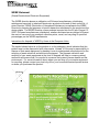
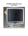
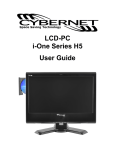
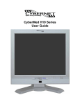
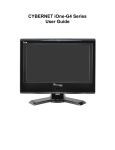
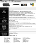
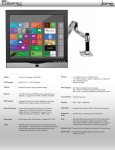
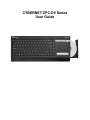
CYBERNET ZPC-D5 Series
User Guide
FCC-B Radio Frequency Interference Statement
This equipment has been tested and found to comply with
the limits for a class B digital device, pursuant to part 15 of the FCC rules. These limits are
designed to provide reasonable protection against harmful interference in a residential
installation. This equipment generates, uses and can radiate radio frequency energy and,
if not installed and used in accordance with the instruction manual, may cause harmful
interference to radio communications. However, there is no guarantee that interference
will not occur in a particular installation. If this equipment does cause harmful interference
to radio or television reception, which can be determined by turning the equipment off and
on, the user is encouraged to try to correct the interference by one or more of the
measures listed below.
• Reorient or relocate the receiving antenna.
• Increase the distance between the equipment and receiver.
• Connect the equipment into an outlet on a circuit different from that to which the
receiver is connected.
• Consult the dealer or an experienced radio/television technician for help.
Notice 1
The changes or modifications not expressly approved by the party
responsible for compliance could void the user's authority to operate the
equipment.
Notice 2
Shielded interface cables and A.C. power cord, if any, must be used in order
to comply with the emission limits.
Trademarks
All trademarks are the properties of their respective owners.
Intel®, Atom™ and Pineview® are registered trademarks of Intel Corporation.
PS/2 and OS®/2 are registered trademarks of International Business Machines
Corporation. Windows® 7/Vista/XP/NT/2000/98/95 are registered trademarks of Microsoft
Corporation. Netware® is a registered trademark of Novell, Inc. Award® is a registered
trademark of Phoenix Technologies Ltd. AMI® is a registered trademark of American
Megatrends Inc
i
Safety Instructions
1.
2.
3.
4.
5.
6.
7.
8.
9.
10.
11.
12.
13.
Always read the safety instructions
carefully.
Keep this equipment away from humidity.
Lay this equipment on a reliable flat surface before setting it up.
The openings on the enclosure are for air convection hence protect the
equipment from overheating. DO NOT COVER THE OPENINGS.
Confirm the voltage of the power source and adjust accordingly to 110/220V
before connecting the equipment to the power inlet.
Place the power cord in such a way that it cannot be stepped on. Do not
place anything over the power cord.
Always unplug the Power Cord before inserting any add-on card or module.
All cautions and warnings on the equipment should be noted.
Never pour any liquid into the opening. This will cause damage and/or electrical
shock.
Do not disable the protective grounding pin from the plug. The equipment must be
connected to a grounded main socket/outlet.
The Optical Storage devices are classified as Class 1 Laser products. Use of
controls or adjustments or performance of procedures other than those specified is
prohibited.
Do not touch the Laser lens inside the optical storage drive.
If any of the following situations arise, have the equipment checked by authorized
service personnel:
• The power cord or plug is damaged.
• Liquid has penetrated into the equipment.
• The equipment has been exposed to moisture.
• The equipment has not worked well or you cannot get it working according to
the User's Guide.
• The equipment has been dropped and damaged.
• The equipment has obvious signs of breakage.
DO NOT LEAVE THIS EQUIPMENT IN AN UNCONDITIONED ENVIRONMENT WITH A
STORAGE TEMPERATURE ABOVE 50° C (122°F). IT MAY DAMAGE THE
EQUIPMENT.
CAUTION: Danger of explosion if battery is incorrectly replaced. Replace only with the
same or equivalent type recommended by the manufacturer.
ii
WEEE Statement
(Waste Electrical and Electronic Equipment)
The WEEE directive places an obligation on EU-based manufacturers, distributors,
retailers and importers to take-back electronics products at the end of their useful life. A
sister Directive, ROHS (Restriction of Hazardous Substances) compliments the WEEE
Directive by banning the presence of specific hazardous substances in the products at the
design phase. The WEEE Directive covers products imported into the EU as of August 13,
2005. EU-based manufacturers, distributors, retailers and importers are obliged to finance
the costs of recovery from municipal collection points, reuse, and recycling of specified
percentages per the WEEE requirements.
Instructions for disposal of WEEE by Users in the European Union
The symbol shown below is on the product or on its packaging, which indicates that this
product must not be disposed of with other waste. Instead, it is the user’s responsibility to
dispose of their waste equipment by handing it over to a designated collection point for the
recycling of waste electrical and electronic equipment. The separate collection and
recycling of your waste equipment at the time of disposal will help to conserve natural
resources and ensure that it is recycled in a manner that protects human health and the
environment. For more information about where you can drop off your waste equipment
for recycling, please contact your local city office, your household waste disposal service
or where you purchased the product.
iii
TABLE OF CONTENTS
FCC-B Radio Frequency Interference Statement ........................................................ i
Trademarks ..................................................................................................................... i
Safety Instructions ........................................................................................................ ii
WEEE Statement .......................................................................................................... iii
Introduction ................................................................................................................... 1
ZPC-D5 Series Specifications ...................................................................................... 1
Processor Support ................................................................................................................1
Chipset ...................................................................................................................................1
Memory Support ....................................................................................................................1
Networking .............................................................................................................................1
Audio ......................................................................................................................................1
Hard Disk Drive ......................................................................................................................1
Expansion Slots .....................................................................................................................1
Function keys.........................................................................................................................1
Right Side of System .............................................................................................................1
Left side of System…………………………………………………………………………………...1
System underneath ...............................................................................................................2
Back I/O ports ........................................................................................................................2
Power Supply .........................................................................................................................2
Dimensions ............................................................................................................................2
ZPC-D5 Series Overview............................................................................................... 3
Keyboard Function keys .......................................................................................................8
Basic operation ....................................................................................................................10
Using the AC adapter ..........................................................................................................10
Using the touchpad .............................................................................................................11
Card reader ..........................................................................................................................12
Wireless ................................................................................................................................12
System Assembly........................................................................................................ 13
Necessary Tools ..................................................................................................................13
Orientation of Key Parts ......................................................................................................14
ZPC-D5 Disassembly ...........................................................................................................15
Installing the Memory Module DDR3 SO-DIMM .................................................................16
Installing the Hard Disk Drive .............................................................................................18
iv
Installing the Mini-PCIe Card (Optional) .............................................................................19
Installing the Optical Drive (Optional) ................................................................................20
All System View…………………………………………………………………………………......24
Cybernet Recycling SOP…………………………………………………………………………..25
Figures
Figure 1: Top View with Optical Disk Drive................................................................. 3
Figure 2: Right side view with Optical Drive ............................................................... 4
Figure 3: Right side top view with Optical Drive ........................................................ 4
Figure 4: Left view and connectors ............................................................................. 5
Figure 5: Back view and connectors ........................................................................... 5
Figure 6: Bottom view ………………….………………………………..…….…………..... 6
Figure 7: CPU Heat Sink Ventilation ............ ……………………………………………..7
Figure 8: Top view power button and LEDs................................................................ 7
Figure 9: Function key (Fn) .......................................................................................... 8
Figure 10: F1-F5 Function keys.................................................................................... 8
Figure 11: Function key F8 ........................................................................................... 9
Figure 12: Other Function keys ................................................................................... 9
Figure 13: Orientation of Key Parts .................................................................. …… 14
v
Introduction
Congratulations on purchasing the ZPC-D5. The ZPC-D5 Series is your best Keyboard
PC choice. With the sleek design and small form factor, it can easily fit on any desktop.
The feature packed platform gives you the power and performance you need.
ZPC-D5 Series Specifications
Processor Support
Intel® Atom™ D525. 1.8Ghz/1M Cache
Chipset
Intel® NM10 chipset
Memory Support
DDR3 800/1066/1333 MHz SO-DIMM SDRAM (Un-buffered Non-ECC)
1 DDR3 1333 MHz SO-DIMM slots (4GB Max)
Networking
Supports PCI Express LAN 10/100/1000 Fast Ethernet by Realtek RTL8111DL
Audio
2 internal speakers @ 1.5W, 1 mic.
HD Audio Codec Realtek® ALC662
Hard Disk Drive
One 2.5” SATA Hard Disk Drive - 500GB/320GB/250GB/160GB
Supports Ultra DMA 66/100 mode
Expansion Slots
2 Mini-PCIe
Function keys
There are eight Fn+Keys in keyboard.
Right Side of System
1 optical disk drive – 2.5” slim
Left Side of System
2 USB 2.0 ports.
3 Audio jacks – Line in, Line Out and Mic
1 MMC,SD,MS/PRO slot.
Cybernet ZPC-D5
User Guide
Page 1
System Underneath
2 Mini-PCIe slot.
1 DDR3 slot.
Back I/O Ports
1 DC/IN port
1 HDMI
1 Video(D-Sub) port
1 LAN RJ-45 jack
2 USB ports
1 Security lock slot
Power Supply
40 Watt Power Adapter, AC Input: 100~240V AC, 1A, 50-60Hz
DC Output: 19V, 2.1A
Dimensions
43cm x 17.2cm x 4cm (W x D x H)
Cybernet ZPC-D5
User Guide
Page 2
ZPC-D5 Series Overview
Figure 1: Top View with Optical Disk Drive
1
No.
2
Item
3
4 5
Detail
1
Keyboard
Standard 86-key USA Keyboard
2
LED indicators
3
Touchpad
LED state indicators for LAN, num/caps lock,
etc.
Functions as optical mouse
4
Reset button or
HDMI/LCD Switch button
5
Power button
Optical Drive
6
6
4.1 When the computer crashes and there is
no HDMI connector in the system, click this
button to reboot the system.
4.2 When there is an HDMI connector in
system, then switch major working screen
toggle mode from LCD to HDMI (or HDMI to
LCD). Screen resolution will be fixed at
1024x768.
Turn computer on/off or enter Standby Mode
DVD-RW
Cybernet ZPC-D5
User Guide
Page 3
Figure 2: Right side view with Optical Drive
1
NO.
1
2
3
2
3
Item
Detail
DVD driver Different computer models are equipped with different drives. The
DVD drive supports CD or DVD discs and have burning (R) or
repeated burning (RW) capabilities.
DVD
This indicator lights when the DVD drive is running.
indicators
Open key Stops the DVD drive and opens the drive tray.
(DVD)
Figure 3: Right side Top view with Optical Drive
Cybernet ZPC-D5
User Guide
Page 4
Figure 4: Left side view and connectors
1
NO.
1
2
2
3
4
5
Item
USB ports
Mic-in
Detail
Connects USB devices
Connects microphone
3
Line-out
Connects earphone or sound box
4
Line-in
External audio input
5
Card reader
Supports MS/MS PRO/SD/MMC card
Figure 5: Back view and connectors
Security lock slot USBs LAN Video HDMI DC-in
NO.
1
2
3
4
5
6
7
Item
Security lock
USB port x2
LAN
Video output
HDMI port
DC-In
Thermal ventilation hole
Cooling vents
Detail
Slot for security lock
Connects USB devices
1GB RJ45 LAN port
External VGA monitor port
HDMI devices
DC Power plug in
Cooling vents for system
Cybernet ZPC-D5
User Guide
Page 5
Figure 6: Bottom view
1
NO.
1
2
3
2
Item
HDD and RAM cover
Speakers
Thermal ventilation holes
3
Detail
Protects hard disk and RAM module
Internal speaker, sound out
Air enters here
Cybernet ZPC-D5
User Guide
Page 6
Figure 7: CPU Heat Sink Ventilation
Figure 8: Top view power button and LEDs
A B C D E
A. Caps Lock Activity (Blue)
B. Number Lock Activity (Blue)
C. Wireless Activity (Blue)
D. Hard disk status indicator (HDD lights, Blue), when the drive is accessing
data, the HDD light flashes.
E. Power LED (Blue)
Cybernet ZPC-D5
User Guide
Page 7
Keyboard Function Keys
There are eight function keys in the keyboard.
Figure 9: Function key (Fn)
Figure 10: F1-F5 Function keys
Cybernet ZPC-D5
User Guide
Page 8
Figure 11: Function key F8
Figure 12: Other Function keys
Fn+Esc: Enter Suspend state.
Fn+F1: Press once to toggle Wireless On or Off.
Fn+F2: Press to increase volume.
Fn+F3: Press to decrease volume.
Fn+F4: Press once to toggle Mute On or Off.
Fn+F8: Press once to toggle Touch Pad On or Off.
Fn+Ins: Press once to toggle Number Lock character capitalization or lowercase letter.
Fn+Del: Press once to toggle auto Screen Lock On or Off.
Cybernet ZPC-D5
User Guide
Page 9
Basic operation
Using the AC adapter
Connect the AC Adapter to your computer as following.
Turning the power on and off
These are only quick instructions for using your new PC. Read the full manual for detailed
information.
A. Connect the AC power cord to the Adapter.
B. Connect the AC adapter to the unit’s DC-in socket.
C. Turn ON the power switch.
Note:
Damage may occur if you use a different adapter to power the computer. You may
damage the computer with a faulty AC-DC adapter.
Press the power switch on the left of the computer to shut it down, or:
Go to [Start] - [Turn Off Computer], select [Shutdown].
Cybernet ZPC-D5
User Guide
Page 10
Using the Touchpad
Use the touchpad to move the cursor on the display and perform normal computer
operations.
NOTE:
By design, the touchpad is to be used with a finger tip only. Therefore, do not use any
implement which could cause damage to the work surface.
A
B
C
A. Work Surface (Touchpad)
B. Left Button
C. Right Button
Function
Operation
Moving the
Move the tip of your finger lightly
cursor
over the work surface
Tapping/Clicking
Double-Clicking
Double-Clicking
Cybernet ZPC-D5
User Guide
Page 11
Dragging
Two quick taps, but on the
second tap leave your finger
down (applying pressure) and
move it on the work surface. Orwhile holding down the button,
move your finger on the work
surface.
Scrolling
1. Select the screen you want to
scroll.
2. Position the cursor over the
area you want to scroll.
3. Trace a line around the right of
the touchpad.
Card Reader
This unit supports MS/MS pro /SD/MMC cards.
Inserting the card:
Insert the card firmly with the label side facing up and with the cut corner in front.
************************************************************
NOTE: Make sure you insert the card in the proper direction. If the card is inserted in the
wrong direction, the card or slot may be damaged.
********************************************
Wireless
1. Press Fn+F1 to activate the wireless LAN function.
2. Select the wireless access point you want to connect to from the list and click
Connect to build the connection. Ensure that the box before “Enable wireless” is
checked.
3. When connecting, you may have to enter a password.
4. After a connection has been established, you can see the wireless signal strength
bars in the Notification area.
Cybernet ZPC-D5
User Guide
Page 12
System Assembly
This chapter provides system assembly information and procedures. While performing
any installation, use a grounded wrist strap before handling computer components and
carefully follow all installation procedures. Static electricity may damage the
components.
This chapter includes instructions for how to install memory modules, the hard disk drive
(HDD), optical disk drive (ODD), and the Mini-PCIe card.
Necessary Tools
A Phillips screwdriver can be used to do most of the installation. One with
a magnetic head is recommended. Applied maximum torque is 5kg.
Pliers can be used as an auxiliary tool to connect some connectors or
cables.
Forceps/tweezers can be used to pick up tiny screws or set up the
jumpers.
Rubber gloves can prevent injury from static charge.
Electric screwdrivers can be used to secure all screws more quickly.
Cybernet ZPC-D5
User Guide
Page 13
Orientation of Key Parts
Figure 13:Orientation of Key Parts: HDD and Optical Drive, Memory Modules and
Mini-PCIe
Optical Drive
HDD
Mini-PCIe Card slot
Cybernet ZPC-D5
Memory Module
User Guide
Page 14
ZPC-D5 Disassembly
ORIENTATION: Presumes the back view of the ZPC is away from you and the bottom
view is nearest you.
1.
Place the ZPC keyboard face down on a padded surface.
2.
Remove the two screws.
3.
Carefully remove the bottom view cover and set aside.
Loosen two
screws to
remove
cover.
Cybernet ZPC-D5
User Guide
Page 15
Installing the Memory Module DDR3 SO-DIMM
1.The memory module has only one notch
and will only fit in the slot one way.
2. Insert the memory module into the DIMM
slot at a 45° angle. Then push it in until the
golden finger on the memory module is
deeply inserted in the DIMM slot.
Cybernet ZPC-D5
User Guide
Page 16
3. Press the memory module down and the
metal clip at each side of the DIMM slot will
automatically close.
Cybernet ZPC-D5
User Guide
Page 17
Installing the Hard Disk Drive
1. Slide the hard disk drive into the frame (SATA connector) and
line up the one screw hole accordingly.
Secure the one screw on the system.
Insert into
the
connector.
Check screw
hole location.
2. Screw the one screw on the system as picture.
disconnect the SATA connector from the
mainboard and set aside in order to gain
access to the Hard Disk Drive slot.
Cybernet ZPC-D5
User Guide
Page 18
Installing the Mini-PCIe Card (Optional)
1. The Mini-PCIe card has only one
notch and will only fit in one way.
Insert the Mini-PCIe card into the
Mini-PCIe slot at a 45° angle.
Then push it in until the golden
finger on the Mini-PCIe card is
deeply inserted in the Mini-PCIe
slot.
2. Press down the Mini-PCIe card
and secure the screw to complete
the installation.
Cybernet ZPC-D5
User Guide
Page 19
Installing the Optical Drive (Optional)
1. Using a screwdriver, press down adjacent to the 4 keys at the locations shown
below to push back restraining clips and release the keyboard matrix.
2. After opening the keyboard, remove it as shown below.
Cybernet ZPC-D5
User Guide
Page 20
3. Loosen the screws and remove the Memory module, Mini-PCIE and HDD as
shown below.
4. Loosen these three connector cables:
4.1 Before
4.2 After
Cybernet ZPC-D5
User Guide
Page 21
5. Remove the keyboard module and loosen these 4 screws as shown below.
6. Remove top case as shown below.
7. Right side-Optical Drive: loosen the cable connector and remove one screw.
Cybernet ZPC-D5
User Guide
Page 22
Then detach the Optical Drive cable connector:
8. View inside with Optical Drive removed:
Detached Optical Drive:
Cybernet ZPC-D5
User Guide
Page 23
All System Views
Front:
Left Side:
Right Side:
Back:
Cybernet ZPC-D5
User Guide
Page 24
Cybernet e-recycling SOP
Cybernet has an e-recycling program that is very easy to use. Just follow the steps
explained below or go to our website at www.cybernetman.com.
1. Request an RMA via phone, email or support request.
2. We will arrange a call tag to have the product picked up. Just have it packed and
ready to ship.
We do the rest!
Cybernet ZPC-D5
User Guide
Page 25